CodeVisionAVR使用教程
- 格式:doc
- 大小:780.50 KB
- 文档页数:9
CodeVisionA VR入门教学和接触新东西一样,很多朋友刚接触CodeVisionA VR感觉无从下手,其实就是一个操作步骤的问题,先会基本的,然后再深入了解它。
CodeVisionAVR是一款非常适合AVR初学者的编译工具,有何特点大家可在网上看看;这里仅讲入门示范,尽量图文详细,不会轻描淡写-如何创建工程和编译,闲话少说;安装方法略过,和其它的软件安装步骤没有什么区别,大家可找找最新版本的。
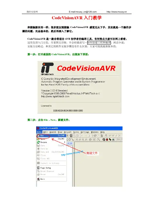
第一步:打开桌面的CodeVisionAVR,出现如下界面:第二步:点击File–New,新建文件:第三步:弹出一个对话框,先选择Source,点击OK-建立源程序文本(呵呵,我们可先从源文本开始、不一定要先建项目的):又弹出一个文本框(下图):第四步:在输完一个完整的程序后,点击File-Save出现对话框,给源程序取个名,后缀名为.C,选好地址,再保存:至此源程序文件已完成,接下来进行关键的第二大步-创建工程第五步:继续点击File–New,这次我们选择是“Project”,再点击OK:接下来的提示框,我们不使用向导模式,点击No:第六步:输入一个工程名称(无需填后缀.prj),和源程序文本放在同一个文件内-保存:第七步:接下来又弹出一个框,点击ADD按钮-添加源程序:按照下图加入源程序:第八步:选择单片机型号和时钟频率,如图:这里选项涉及单片机型号、时钟、存储器类型等设置,初学者可先对其它的不做变动。
设置好了点击OK完成!第九步:点击Project–Build ALL,或者按下Ctrl+F9进行编译:出现报告信息(下图),无论是否出现错误提示,整个步骤是完成了!第十步:查看你的CV AVR项目和程序文件夹其它:编译错误:如果您的程序有问题,比如下面有反显提示:例:以上提示“PORTD_3”位名称错误(即PD3端口),正确应为“PORTD.3”。
CodeVisionAVR是非常优秀的,界面友好,是初学者的首选,大家可登录我们的网站或者在其它网站找相关经验和例程,十分容易上手的工具,当然每个人的爱好不同,只要能对自己学习AVR单片机方便就行,毕竟一个良好的编译环境是很重要的!。

利用Code Vision AVR C中断程序实现AVR单片机的TWI读写在AVR单片机的开发过程中,TWI(Two-Wire Interface)总线通信协议是较为常用的一种方式。
我们可以利用CodeVision AVR C中断程序来实现AVR单片机的TWI读写。
首先,我们需要了解一下TWI通信协议的基本原理。
TWI总线上有两条线路,一条为SCL时钟线,另一条为SDA数据线。
两条线路上都有上拉电阻,数据传输时由主机(如AVR单片机)控制SCL时钟线和SDA数据线的电平变化来进行数据传输。
在Code Vision AVR C中,我们可以利用TWI库函数进行TWI通信的操作。
在进行TWI读写时,我们需要先发送起始信号,然后发送设备地址和读写指令,接着进行数据传输,最后发送停止信号。
这一系列操作可以使用TWI库函数中的相应函数来完成。
在使用中断程序时,我们需要使TWI模块开启中断功能,并定义好中断服务程序。
在TWI传输过程中,当一个操作完成后,TWI模块会触发中断,执行相应的中断服务程序。
在中断服务程序中,我们可以处理TWI传输过程中出现的各种情况,如传输完成、传输错误等。
下面以TWI读取一个EEPROM芯片中的数据为例,说明如何利用Code Vision AVR C中断程序实现TWI读写。
假设EEPROM芯片的I2C地址为0xA0,我们需要读取从地址0x00开始的8个字节的数据。
首先,我们需要在程序的头文件中引用Code Vision AVR C提供的TWI库。
#include <mega328p.h>#include <delay.h>#include <twi.h>接着,定义TWI芯片地址和读写指令。
#define EEPROM_WRITE 0xA0#define EEPROM_READ 0xA1定义存储数据的缓冲区。
unsigned char EEPROM_Buffer[8];在主函数中初始化TWI模块,并开启TWI中断。

翻译:谢剑波2008年5月20日声明:本手册是根据CodeVisionA VR V1.25.3 User Manual英文原文翻译而成,最初目的是用于本人和本人的学生学习之用,现将其整理成册,免费提供给各位初学者学习使用。
本手册可免费使用,但切务用于商业用途,如果因此而导致版权纠纷,责任自负。
由于本人英文水平有限,加之本从也正在学习A VR,所以其中难免有错,望各位谅解并不吝赐教,本人将不胜感激。
本人联系方法:e-mail:coolbor@QQ:947988474(很少登录)Blog:/coolbor/谢剑波2008年5月20日目 录目 录 (2)第1章概述 (4)第2章 CodeVisionAVR集成开发环境(IDE) (5)2.1 文件操作 (5)2.1.1 创建一个新文件 (5)2.1.2 操作一个已经存在的文件 (5)2.1.3 文件历史 (5)2.1.4 编辑文件 (6)2.1.5 保存文件 (6)2.1.6 重命名文件 (6)2.1.7 打印文件 (7)2.1.8 关闭文件 (7)2.1.9 使用导航器 (8)2.1.10 使用代码模板 (9)2.1.11 使用粘贴板历史 (9)2.2项目操作 (10)2.2.1 创建新项目 (10)2.2.2 打开已经存在的项目 (11)2.2.3 添加记录或命令到项目 (11)2.2.4 配置项目 (12)2.2.4.1 从项目添加或移除文件 (12)2.2.4.2 设置C编译器选项 (13)2.2.4.3 在Make前执行用户指定的程序 (18)2.2.4.4 在Make后将已经编译的程序传送至A VR芯片 (19)2.2.4.5 在Make之后执行用户指定的程序 (20)2.2.5 生成一个可执行的程序 (21)2.2.5.1 检查项目的语法错误 (22)2.2.5.2 编译项目 (22)2.2.5.3 Making the Project (23)2.2.6 关闭项目 (25)2.3 工具(Tools) (25)2.3.1 A VR Studio Debugger (25)2.3.2 A VR Chip Programmer (26)2.3.3 串行通信终端 (28)2.3.4 执行用户程序 (29)2.3.4.1 配置Tools菜单 (29)2.4 IDE设置 (30)2.4.1 View菜单 (30)2.4.2 配置Editor (30)2.4.3 配置Assembler (31)2.4.4 设置Debugger路径 (31)2.4.5 A VR芯片Programmer设置 (32)2.4.6 串行通信Terminal设置 (33)2.5 访问Help (34)2.6 传送License到另一台计算机 (34)2.7 连接到HP InfoTech网站 (34)2.8 通过E-Mail联系HP InfoTech (34)2.9 退出CodeVisionA VR IDE (34)第1章概述CodeVisionA VR是一款专为Atmel A VR系列微控制器而设计的交互式C编译器、集成开发环境(IDE)和自动程序生成器(APG)。


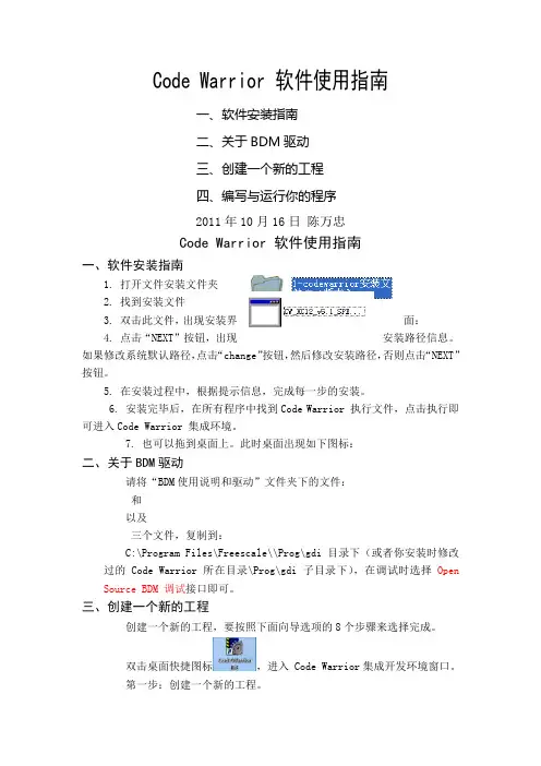
Code Warrior 软件使用指南一、软件安装指南二、关于BDM驱动三、创建一个新的工程四、编写与运行你的程序2011年10月16日陈万忠Code Warrior 软件使用指南一、软件安装指南1. 打开文件安装文件夹2. 找到安装文件3. 双击此文件,出现安装界面:4. 点击“NEXT”按钮,出现安装路径信息。
如果修改系统默认路径,点击“change”按钮,然后修改安装路径,否则点击“NEXT”按钮。
5. 在安装过程中,根据提示信息,完成每一步的安装。
6. 安装完毕后,在所有程序中找到Code Warrior 执行文件,点击执行即可进入Code Warrior 集成环境。
7. 也可以拖到桌面上。
此时桌面出现如下图标:二、关于BDM驱动请将“BDM使用说明和驱动”文件夹下的文件:和以及三个文件,复制到:C:\Program Files\Freescale\\Prog\gdi目录下(或者你安装时修改过的Code Warrior 所在目录\Prog\gdi子目录下),在调试时选择Open Source BDM 调试接口即可。
三、创建一个新的工程创建一个新的工程,要按照下面向导选项的8个步骤来选择完成。
双击桌面快捷图标,进入 Code Warrior集成开发环境窗口。
第一步:创建一个新的工程。
第二步:选择CPU类型,选择HCS12X目录下的HCS12X Family。
第三步:选择CPU芯片型号和BDM工具TBDML。
第四步:选择编程语言,我们选择C语言编程。
第五步:添加文件到工程,一般直接按“下一步”。
第六步:快速开发应用程序选择,选None。
第七步:选择中的用户自定义模式。
第八步:选择不使用PC-Lint(TM)链接工具软件,点击“完成”按钮,Code Warrior集成开发环境就会自动生成整个工程的文件系统。
四、编写与运行你的程序在Code Warrior集成开发环境中,利用其自动生成的函数模板,就可以编写和调试你的应用程序了。

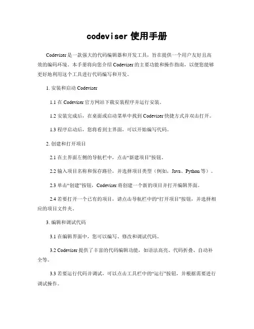
codeviser使用手册Codeviser是一款强大的代码编辑器和开发工具,旨在提供一个用户友好且高效的编码环境。
本手册将向您介绍Codeviser的主要功能和操作指南,以便您能够更好地利用这个工具进行代码编写和开发。
1. 安装和启动Codeviser1.1 在Codeviser官方网站下载安装程序并运行安装。
1.2 安装完成后,在桌面或启动菜单中找到Codeviser快捷方式并双击打开。
1.3 程序启动后,您将看到主界面,可以开始编写代码。
2. 创建和打开项目2.1 在主界面左侧的导航栏中,点击“新建项目”按钮。
2.2 输入项目名称和保存路径,并选择项目类型(例如,Java、Python等)。
2.3 单击“创建”按钮,Codeviser将创建一个新的项目并打开编辑界面。
2.4 若要打开一个已有的项目,请点击导航栏中的“打开项目”按钮,并选择相应的项目文件夹。
3. 编辑和调试代码3.1 在编辑界面中,您可以编写、修改和调试代码。
3.2 Codeviser提供了丰富的代码编辑功能,如语法高亮、代码折叠、自动补全等。
3.3 若要运行代码并调试,可以点击工具栏中的“运行”按钮,并根据需要进行调试操作。
4. 版本控制和协作4.1 Codeviser集成了常见的版本控制工具,如Git和SVN,方便团队开发和代码管理。
4.2 您可以在编辑界面中进行代码版本控制,如提交、拉取、推送等操作。
4.3 Codeviser还支持与团队成员进行协作,您可以分享代码、进行代码审查和讨论。
5. 插件和扩展5.1 Codeviser提供了丰富的插件和扩展,可根据个人需求进行安装和使用。
5.2 通过插件和扩展,您可以增强Codeviser的功能,如代码格式化、代码片段、主题等。
6. 帮助和支持6.1 在Codeviser的官方网站上可以找到更多关于使用和故障排除的帮助文档和资源。
6.2 如果您遇到问题或需要进一步的支持,请访问官方网站上的社区论坛或联系技术支持团队。
CodeVisionAVR C 编译器参考1CodeVisionAVR C Compiler ReferenceCodeVisionAVR C 编译器参考翻译自CodeVisionAVR C Compiler Help目录1. Comments -注释2. Reserved Keywords -关键字3. Identifiers -标识符4. Data Types -数据类型5. Constants -常量6. Variables -变量7. Specifying the SRAM Storage Address for Global Variables -指定全局变量在SRAM 的地址8. Bit Variables -位变量9. Allocation of Variables to Registers -给变量分配寄存器10. Structures -结构体11. Unions -联合12. Enumerations -枚举13. Global Variables Memory Map File -全局变量存储器分配映象文件14. Type Conversions -数据类型转换15. Operators -运算符16. Functions -函数17. Pointers -指针18. Accessing the I/O Registers -访问I/O寄存器19. Bit level access to the I/O Registers -I/O寄存器的位访问20. Accessing the EEPROM -访问EEPROM21. Using Interrupts -使用中断22. The Preprocessor -预编译23. SRAM Memory Organization -SRAM 结构24. Including Assembly Language in Your Program -在程序中嵌入汇编语言25. Calling Assembly Functions from C -在C 中调用汇编子程序26. Creating Libraries -建立自己的库27. Using the AVR Studio Debugger -使用AVR Studio Debugger 调试程序28. Hints -提示29. Limitations -限制CodeVisionAVR C 编译器参考-刘汧21、Comments -注释注释由"/*" 开始,"*/" 结束。
CodeVisionARV使用教程一、打开CodeVisionARV软件
二、File New,新建Source文档,点击Ok。
三、在新建的文档中输入C程序之后,保存,弹出对话框,保存在指定的路径中。
四、File New,新建Project文档,点击Ok。
之后弹出的对话框中选择No。
之后,选择工程保存的路径及名称。
五、保存之后弹出Configure Project test对话框,点击Add,将之前的C程序文档加入工程,之后点击Ok。
或者点击Project Configure,弹出Configure Project test对话框,添加C程序文档。
并在Configure Project test对话框中选择C Compiler选项卡,选择Code Generation选项卡,中Chip选项,选择ATmega128芯片,点击OK。
四、Project Build All,编译源程序,或者点击按钮编译,之后会弹出Information对话框,提示错误等信息。
生成的.hex 文件在Exe文件夹中。
CodeVisionAVRC编译器使用介绍
在CodeVision AVR中,我们可以使用C语言编写程序。
C语言是一
种非常强大和灵活的编程语言,适用于各种应用场景。
在CodeVision
AVR中,我们可以使用C语言来编写控制程序、处理输入输出和实现各种
功能。
在编写完代码后,我们可以点击“编译”按钮来编译代码。
CodeVision AVR会将C代码转换为AVR微控制器可以执行的机器码。
编
译过程中,我们可以在编译输出窗口中查看编译器的输出信息。
如果代码
中存在错误,编译器会给出相应的错误提示,我们需要根据提示进行修复。
在编译成功后,我们可以将生成的机器码烧录到AVR微控制器中。
CodeVision AVR提供了与各种烧录器的集成,可以方便地将程序烧录到
目标设备中。
烧录完成后,我们可以测试程序的功能和性能。
除了编译和烧录功能,CodeVision AVR还提供了强大的调试功能。
我们可以使用调试器来单步执行程序、查看变量的值和监视程序的执行过程。
调试过程中,我们可以在调试窗口中设置断点和观察点,以便更好地
理解程序的执行过程和调试问题。
总结起来,CodeVision AVR是一款功能强大的AVR微控制器编译器。
它提供了丰富的功能和直观的用户界面,使得编写和调试AVR微控制器程
序变得更加简单和高效。
无论是初学者还是有经验的开发者,都可以从CodeVision AVR的使用中受益匪浅。
1AVR033: Getting Started with theCodeVisionAVR C CompilerFeatures•Installing and Configuring CodeVisionAVR to Work with the Atmel STK500 Starter Kit and AVR Studio ® Debugger•Creating a New Project Using the CodeWizardAVR Automatic Program Generator •Editing and Compiling the C Code•Loading the Executable Code into the Target Microcontroller on the STK500 Starter Kit IntroductionThe purpose of this application note is to guide the user through the preparation of an example C program using the CodeVisionAVR C compiler. The example, which is the subject of this application note, is a simple program for the Atmel AT90S8515 micro-controller on the STK500 starter kit.PreparationInstall the CodeVisionAVR C Compiler in the default directory: C:\cvavr.Install the Atmel AVR Studio debugger in the default directory:C:\Program Files\Atmel\AVR Studio.The demonstration program to be developed in the next few pages requires an Atmel AT90S8515 microcontroller and the STK500 starter kit.Set up the starter kit according to the instructions in the STK500 User Guide.Make sure the power is off and insert the AT90S8515 chip into the appropriate socket marked SCKT3000D3.Set the VTARGET, RESET, and XTAL1 jumpers. Also set the OSCSEL jumper between pins 1 and 2.Connect one 10-pin ribbon cable between the PORTB and LEDs headers.This will allow displaying the state of AT90S8515’s PORTB outputs.Connect one 6-pin ribbon cable between the ISP6PIN and SPROG3 headers.This will allow the CodeVisionAVR IDE to automatically program the AVR chip after a successful compilation.In order to use this feature, one supplementary setting must be done:Open the CodeVisionAVR IDE and select the “Settings|Programmer ” menu option.The dialog window as shown in Figure 1 will open.8-bitMicrocontroller Application2AVR033 2500B –AVR –05/02Figure 1. Programmer SettingsMake sure to select as Chip Programmer Type the Atmel STK500 AVR and the corre-sponding Communication Port that is used with the STK500 starter kit.Then press the “STK500.EXE Directory ” button in order to specify the location of the stk500.exe command line utility supplied with AVR Studio.The dialog window as shown in Figure 2 will open.Figure 2. Directory Selection Select the “c:\Program Files\Atmel\AVR Studio\STK500” directory and press the “OK ”button.Then press once again the “OK ” button in order to save the Programmer Settings.In order to be able to invoke the AVR Studio debugger from within the CodeVisionAVR IDE one final setting must be done.3AVR0332500B –AVR –05/02Select the “Settings|Debugger ” menu option. The dialog window as shown in Figure 3will open.Figure 3. Debugger SettingsEnter “C:\Program Files\Atmel\AVR Studio\AvrStudio.exe” and press the“OK ” button.Creating a NewProject In order to create a new project, select the “File|New ” menu option or press thetool-bar button.The window shown in Figure 4 will be displayed.Figure 4. New Project Window Select “Project ” and press “OK ”.Then the window shown in Figure 5 will be displayed.Figure 5. ConfirmationPress “Yes ” to use the CodeWizardAVR Automatic Program Generator.4AVR033 2500B –AVR –05/02Using theCodeWizardAVRAutomatic Program GeneratorThe CodeWizardAVR simplifies the task of writing start-up code for different AVR microcontrollers.Figure 6.Selections The window shown in Figure 6 opens and, for this example project, we shall select the AT90S8515 microcontroller and set the clock rate to 3.68 MHz since that is the clock on the STK500 starter kit.5AVR0332500B –AVR –05/02Configuring theInput/Output Ports Select the “Ports ” tab to determine how the I/O ports are to be initialized for the targetsystem.Figure 7. I/O Ports InitializationThe default setting is to have the ports for all the target systems to be inputs (Data Direction bits to be all Is) in their Tri-state mode.For this exercise, we want to set Port B (by selecting the Port B tab) to be all outputs and we do this by setting all the Data Direction bits to O (by clicking on them). We also set the Output Values to be all 1s since this corresponds to the LEDs on the STK500 beingoff.6AVR033 2500B –AVR –05/02Configuring Timer1For this project, we want to configure Timer1 to generate overflow interrupts.We select the Timers tab and then select the Timer1 tab resulting in Figure 8.Figure 8. Timer Tab Set the options as shown in Figure 8. We have selected a clock rate of 3.594 kHz (the system clock of 3.68 MHz divided by 1024).The timer is set to operate in the default “Output Compare ” mode and to generate inter-rupts on overflow.To obtain the frequency of LED movement of two per second we need to reinitialize the Timer1 value to 0x10000-(3594/2) = 0xF8FB on every pleting theProjectBy selecting the File|Generate, Save and Exit menu option the CodeWizard will gener-ate a skeleton C program with, in this case, the Port B and Timer1 Overflow Interrupt set up correctly.The dialog window shown in Figure 9 will appear.Figure 9.Save Source File Dialog Box7AVR0332500B –AVR –05/02By pressing the button, a new directory C:\cvavr\led must be created.It will hold all the files of our sample project.Then we must specify the File name of the C source file: led.c and press the “Save ”button.A new dialog window will open. This is shown in Figure 10.Figure 10. File Name SpecificationHere, we must specify the File name led.prj, as the project name and put it in the same folder: C:\cvavr\led.Finally, we will be prompted to save the CodeWizard project file, as shown in Figure 11.Figure 11. File Save PromptWe must specify the File name as led.cwp and press the “Save ” button.Saving all the CodeWizardAVR peripherals configuration in the led.cwp project file, will allow us to reuse some of our initialization code in future projects.The led.c source file is now automatically opened and available.One can then start editing the code produced by the CodeWizardAVR.The source listing is given on Appendix A of this application note.In this example, only the interrupt handler code needs to be amended to manage the LED display.The small bit of code that was added is shown with bold font, the remainder was sup-plied by the CodeWizardAVR.8AVR033 2500B –AVR –05/02Viewing or Modifying the ProjectConfigurationAt any time, a project configuration may be changed using the Project|Configure menu option or by pressing the toolbar button.The dialog window shown in Figure 12 will open.Figure 12. Configure Window Dialog BoxTo add, respectively remove, files from the project select the “Files ” tab and use the “Add ”, respectively “Remove ” buttons.To change the target microcontroller, the clock rate or the various compiler options select the “C Compiler ” tab.The dialog box shown in Figure 13 opens and the configuration may be altered.Figure 13. C Compiler Configuration9AVR0332500B –AVR –05/02We may also select whether we wish to automatically program the target microproces-sor after the Make or not.This is chosen by selecting the “After Make ” tab, which gives us the next window, shown in Figure 14.Figure 14.After Make Configuration For the purposes of this example, “Program the Chip ” option must be checked.This will enable automatic programming of the AVR chip after the Make is complete.10AVR033 2500B –AVR –05/02Making the Project The “Project ” Pull-down menu gives the Make option. Click on it or on the button on the toolbar. After a successful compile and assembly, the Information window will be displayed as shown in Figure 15.Figure 15. Information Window This window shows how the compiler used the RAM memory.If the Assembler tab is clicked, the Assembler window shows the size of the assembledcode as shown in Figure 16.11AVR0332500B –AVR –05/02Figure 16. Assembler InformationSelecting the Programmer tab displays the value of the Chip Programming Counter.Pressing the Set Counter button can initialize this counter.12AVR0332500B –AVR –05/02Figure 17. Programmer InformationIf the Make process was successful, then power-up the STK500 starter kit and press the Program button to start the automatic chip programming.After the programming process is complete, the code will start to execute in the target microcontroller on the STK500 starter kit.Short ReferencePreparations1.Install the CodeVisionAVR C Compiler2.Install the Atmel AVR Studio Debugger3.Install the Atmel STK500 Starter Kit4.Configure the STK500 Programmer Support in the CodeVisionAVR IDE byselecting: Settings →Programmer →AVR Chip Programmer Type: STK500→Specify STK500.EXE Directory: C:\Program Files\Atmel\AVR Studio\STK500→Communication Port 5.Configure the AVR Studio Support in the CodeVisionAVR IDE by selecting:Settings →Debugger →Enter: C:\Program Files\Atmel\AVR Studio13AVR0332500B –AVR –05/02Getting Started1.Create a new project by selecting:File →New →Select Project2.Specify that the CodeWizardAVR will be used for producing the C source andproject files: Use the CodeWizard?→Yes 3.In the CodeWizardAVR window specify the chip type and clock frequency:Chip →Chip: AT90S8515→Clock: 3.86MHz 4.Configure the I/O Ports: Ports →Port B →Data Direction: all Outputs →Output Value: all 1’s5.Configure Timer1: Timers →Timer1→Clock Value: 3.594kHz →Interrupt on: Timer1 Overflow →Val: 0xF8FB6.Generate the C source, C project and CodeWizardAVR project files by selecting:File|Generate, Save and Exit →Create new directory: C:\cvavr\led →Save: led.c →Save: led.prj →Save: led.cwp 7.Edit the C source code8.View or Modify the Project Configuration by selecting Project →Configure →After Make →Program the Chip pile the program by selecting:Project →Make10.Automatically program the AT90S8515 chip on the STK500 starter kit:Apply power →Information →Program.Appendix A - The Source Code/*********************************************This program was produced by the CodeWizardAVR V1.0.1.8c Standard Automatic Program Generator © Copyright 1998-2001Pavel Haiduc, HP InfoTech S.R.L.http://infotech.ir.roe-mail: hpinfotech@xnet.ro, hpinfotech@xmail.ro Project : Version : Date :Author :Company :Comments:Chip type : AT90S8515Clock frequency : 3.680000 MHz Memory model : Small Internal SRAM size : 512External SRAM size : 0Data Stack size : 128*********************************************/#include <90s8515.h>14AVR0332500B –AVR –05/02// the LED 0 on PORTB will be on unsigned char led_status=0xFE;// Timer 1 overflow interrupt service routine interrupt [TIM1_OVF] void timer1_ovf_isr(void){// Reinitialize Timer’s 1 value TCNT1H=0xF8;TCNT1L=0xFB;// Place your code here // move the LED led_status<<=1;led_status|=1;if (led_status==0xFF) led_status=0xFE;// turn on the LED PORTB=led_status;}void main(void){// Input/Output Ports initialization // Port A PORTA=0x00;DDRA=0x00;// Port B PORTB=0xFF;DDRB=0xFF;// Port C PORTC=0x00;DDRC=0x00;// Port D PORTD=0x00;DDRD=0x00;// Timer/Counter 0 initialization // Clock source: System Clock // Clock value: Timer 0 Stopped // Mode: Output Compare // OC0 output: Disconnected TCCR0=0x00;TCNT0=0x00;// Timer/Counter 1 initialization // Clock source: System Clock // Clock value: 3.594 kHz15AVR0332500B –AVR –05/02// Mode: Output Compare // OC1A output: Discon.// OC1B output: Discon.// Noise Canceler: Off// Input Capture on Falling Edge TCCR1A=0x00;TCCR1B=0x05;TCNT1H=0xF8;TCNT1L=0xFB;OCR1AH=0x00;OCR1AL=0x00;OCR1BH=0x00;OCR1BL=0x00;// External Interrupt(s) initialization // INT0: Off // INT1: Off GIMSK=0x00;MCUCR=0x00;// Timer(s)/Counter(s) Interrupt(s) initialization TIMSK=0x80;// Analog Comparator initialization // Analog Comparator: Off// Analog Comparator Input Capture by Timer/Counter 1: Off ACSR=0x80;// Global enable interrupts #asm("sei")// the rest is done by TIMER1 overflow interrupts while (1);}© Atmel Corporation 2002.Atmel Corporation makes no warranty for the use of its products, other than those expressly contained in the Company ’s standard warranty which is detailed in Atmel ’s Terms and Conditions located on the Company ’s web site. The Company assumes no responsibility for any errors which may appear in this document, reserves the right to change devices or specifications detailed herein at any time without notice, and does not make any commitment to update the information contained herein. No licenses to patents or other intellectual property of Atmel are granted by the Company in connection with the sale of Atmel products, expressly or by implication. Atmel ’s products are not authorized for use as critical components in life support devices or systems.Atmel HeadquartersAtmel OperationsCorporate Headquarters2325 Orchard Parkway San Jose, CA 95131TEL 1(408) 441-0311FAX 1(408) 487-2600EuropeAtmel SarlRoute des Arsenaux 41Case Postale 80CH-1705 Fribourg SwitzerlandTEL (41) 26-426-5555FAX (41) 26-426-5500AsiaRoom 1219Chinachem Golden Plaza 77 Mody Road Tsimhatsui East Kowloon Hong KongTEL (852) 2721-9778FAX (852) 2722-1369Japan9F, Tonetsu Shinkawa Bldg.1-24-8 ShinkawaChuo-ku, Tokyo 104-0033JapanTEL (81) 3-3523-3551FAX (81) 3-3523-7581Memory2325 Orchard Parkway San Jose, CA 95131TEL 1(408) 441-0311FAX 1(408) 436-4314Microcontrollers2325 Orchard Parkway San Jose, CA 95131TEL 1(408) 441-0311FAX 1(408) 436-4314La Chantrerie BP 7060244306 Nantes Cedex 3, France TEL (33) 2-40-18-18-18FAX (33) 2-40-18-19-60ASIC/ASSP/Smart CardsZone Industrielle13106 Rousset Cedex, France TEL (33) 4-42-53-60-00FAX (33) 4-42-53-60-011150 East Cheyenne Mtn. Blvd.Colorado Springs, CO 80906TEL 1(719) 576-3300FAX 1(719) 540-1759Scottish Enterprise Technology Park Maxwell BuildingEast Kilbride G75 0QR, Scotland TEL (44) 1355-803-000FAX (44) 1355-242-743RF/AutomotiveTheresienstrasse 2Postfach 353574025 Heilbronn, Germany TEL (49) 71-31-67-0FAX (49) 71-31-67-23401150 East Cheyenne Mtn. Blvd.Colorado Springs, CO 80906TEL 1(719) 576-3300FAX 1(719) 540-1759Biometrics/Imaging/Hi-Rel MPU/High Speed Converters/RF DatacomAvenue de Rochepleine BP 12338521 Saint-Egreve Cedex, France TEL (33) 4-76-58-30-00FAX (33) 4-76-58-34-80e-mailliterature@Web Site2500B –AVR –05/020MATMEL ®, AVR ®, and AVR Studio ® are the registered trademarks of Atmel.Other terms and product names may be the trademarks of others.。
矿产资源开发利用方案编写内容要求及审查大纲
矿产资源开发利用方案编写内容要求及《矿产资源开发利用方案》审查大纲一、概述
㈠矿区位置、隶属关系和企业性质。
如为改扩建矿山, 应说明矿山现状、
特点及存在的主要问题。
㈡编制依据
(1简述项目前期工作进展情况及与有关方面对项目的意向性协议情况。
(2 列出开发利用方案编制所依据的主要基础性资料的名称。
如经储量管理部门认定的矿区地质勘探报告、选矿试验报告、加工利用试验报告、工程地质初评资料、矿区水文资料和供水资料等。
对改、扩建矿山应有生产实际资料, 如矿山总平面现状图、矿床开拓系统图、采场现状图和主要采选设备清单等。
二、矿产品需求现状和预测
㈠该矿产在国内需求情况和市场供应情况
1、矿产品现状及加工利用趋向。
2、国内近、远期的需求量及主要销向预测。
㈡产品价格分析
1、国内矿产品价格现状。
2、矿产品价格稳定性及变化趋势。
三、矿产资源概况
㈠矿区总体概况
1、矿区总体规划情况。
2、矿区矿产资源概况。
3、该设计与矿区总体开发的关系。
㈡该设计项目的资源概况
1、矿床地质及构造特征。
2、矿床开采技术条件及水文地质条件。