电气系统的保护(外文文献翻译)
- 格式:doc
- 大小:40.00 KB
- 文档页数:7
Circuit breaker断路器Compressed air circuit breaker is a mechanical switch equipment, can be i 空气压缩断路器是一种机械开关设备,能够在n normal and special conditions breaking current (such as short circuit cur 正常和特殊情况下开断电流(比如说短路电流)。
rent). For example, air circuit breaker, oil circuit breaker, interference circ 例如空气断路器、油断路器,干扰电路的导体uit conductor for the application of the safety and reliability of the circuit 干扰电路的导体因该安全可靠的应用于其中,breaker, current in arc from is usually divided into the following grades: a 电流断路器按灭弧远离通常被分为如下等级:ir switch circuit breaker, oil circuit breaker, less oil circuit breaker, compr 空气开关断路器、油断路器、少油断路器、压缩空essed air circuit breaker, a degaussing of isolating switch, six sulfur hexaf 气断路器、具有消磁性质的隔离开关、六氟luoride circuit breaker and vacuum breaker. Their parameters of voltage, 化硫断路器和真空断路器。
他们的参数有电压等级、current, insulation level of breaking capacity, instantaneous voltage off ti 开断容量的电流、绝缘等级开断时间的瞬时电压恢复和me of recovery and a bombing. Breaker plate usually include: 1 the maxi 轰炸时间。
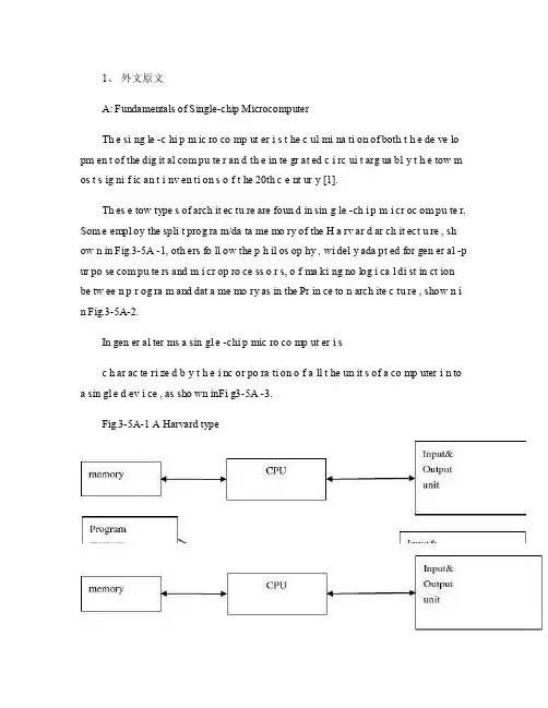
1、外文原文A: Fundamentals of Single-chip MicrocomputerTh e si ng le -c hi p m ic ro co mp ut er i s t he c ul mi na ti on of both t h e de ve lo pm en t of the dig it al com pu te r an d th e in te gr at ed c i rc ui t arg ua bl y t h e tow m os t s ig ni f ic an t i nv en ti on s o f t he 20th c e nt ur y [1].Th es e tow type s of arch it ec tu re are foun d in sin g le -ch i p m i cr oc om pu te r. Som e empl oy the spli t prog ra m/da ta me mo ry of the H a rv ar d ar ch it ect u re , sh ow n in Fig.3-5A -1, oth ers fo ll ow the p h il os op hy , wi del y ada pt ed for gen er al -p ur po se com pu te rs and m i cr op ro ce ss o r s, o f ma ki ng no log i ca l di st in ct ion be tw ee n p r og ra m and dat a me mo ry as in the Pr in ce to n arch ite c tu re , show n i n Fig.3-5A-2.In gen er al ter ms a sin gl e -chi p mic ro co mp ut er i sc h ar ac te ri zed b y t he i nc or po ra ti on of a ll t he un it s of a co mp uter i n to a sin gl e d ev i ce , as sho wn inFi g3-5A -3.Fig.3-5A-1 A Harvard typeFig.3-5A-2. A conventional Princeton computerFig3-5A-3. Principal features of a microcomputerRead only memory (ROM.R OM is usua ll y for the pe rm an ent,n o n-vo la ti le stor a ge of an app lic a ti on s pr og ra m .M an ym i cr oc om pu te rs and m are inte nd e d for high -v ol um e ap pl ic at ions a n d he nc e t h e eco n om ic al man uf act u re of th e de vic e s re qu ir es t h at t he cont en t s o f t he prog ra m me m or y be co mm it t ed perm a ne ntly d u ri ng the man ufa c tu re of ch ip s .Cl ea rl y, thi s im pl ie s a r i go ro us app ro ach to ROM cod e deve l op me nt sin ce cha ng es can not b e mad e afte r manu f a c tu re .Th is dev e lo pm en t proc ess may invo lv e e m ul at io n us in g aso ph is ti ca te d de ve lo pm en t sy ste m wit h a h a rd wa re emu la tio n cap ab il it y as w el l as the use o f po we rf ul s o ft wa re too ls.So me man uf act u re rs pro vi de add it io na l RO M opt i on s by i n cl ud in g in their ra n ge dev ic es wit h (or int en de d fo r use wit h u s er pro gr am ma ble me mo ry. Th e sim p le st of th es e is usu al ly d e vi ce whi ch can op er at e in a micro p ro ce ssor mod e by usi ng som e o f the inp ut /outp u t li ne s as an ad dr es s an d da ta b us fora c ce ss in g ex te rna l mem or y. Thi s t y pe of de vi ce can beh av ef u nc ti on al ly as th e sing le chip mi cr oc om pu te r from whi ch it is d e ri ve d al be it wit h re st ri ct ed I/O and a mod if ied ex te rn al c i rc ui t. The use of thes e d ev ic es is com mo n eve n in prod uc ti on c i rc ui ts wher e t he vo lu me does no tj us ti f y t h e d ev el o pm en t c osts o f c us to m o n -ch i p R OM [2];t he re c a n s ti ll bea s ignif i ca nt saving i n I /O and o th er c h ip s com pa re d to a conv en ti on al mi c ro pr oc es sor b a se d ci rc ui t. Mor e ex ac t re pl ace m en t fo r RO M dev i ce s ca n be o b ta in ed in th e fo rm of va ri an ts w it h 'p ig gy -b ack 'E P RO M(Er as ab le pro gr am ma bl e ROM s oc ke ts or dev ic e s with EPROM i n st ea d o f RO M 。
外文出处:Farhadi, A. (2008). Modeling, simulation, and reduction of conducted electromagnetic interference due to a pwm buck type switching power supply. Harmonics and Quality of Power, 2008. ICHQP 2008. 13th International Conference on, 1 - 6.Modeling, Simulation, and Reduction of Conducted Electromagnetic Interference Due to a PWM Buck Type Switching Power Supply IA. FarhadiAbstract:Undesired generation of radiated or conducted energy in electrical systems is called Electromagnetic Interference (EMI). High speed switching frequency in power electronics converters especially in switching power supplies improves efficiency but leads to EMI. Different kind of conducted interference, EMI regulations and conducted EMI measurement are introduced in this paper. Compliancy with national or international regulation is called Electromagnetic Compatibility (EMC). Power electronic systems producers must regard EMC. Modeling and simulation is the first step of EMC evaluation. EMI simulation results due to a PWM Buck type switching power supply are presented in this paper. To improve EMC, some techniques are introduced and their effectiveness proved by simulation.Index Terms:Conducted, EMC, EMI, LISN, Switching SupplyI. INTRODUCTIONFAST semiconductors make it possible to have high speed and high frequency switching in power electronics []1. High speed switching causes weight and volume reduction of equipment, but some unwanted effects such as radio frequency interference appeared []2. Compliance with electromagnetic compatibility (EMC) regulations is necessary for producers to present their products to the markets. It is important to take EMC aspects already in design phase []3. Modeling and simulation is the most effective tool to analyze EMC consideration before developing the products. A lot of the previous studies concerned the low frequency analysis of power electronics components []4[]5. Different types of power electronics converters are capable to be considered as source of EMI. They could propagate the EMI in both radiated and conducted forms. Line Impedance Stabilization Network (LISN) is required for measurement and calculation of conducted interference level []6. Interference spectrum at the output of LISN is introduced as the EMC evaluation criterion []7[]8. National or international regulations are the references forthe evaluation of equipment in point of view of EMC []7[]8.II. SOURCE, PATH AND VICTIM OF EMIUndesired voltage or current is called interference and their cause is called interference source. In this paper a high-speed switching power supply is the source of interference.Interference propagated by radiation in area around of an interference source or by conduction through common cabling or wiring connections. In this study conducted emission is considered only. Equipment such as computers, receivers, amplifiers, industrial controllers, etc that are exposed to interference corruption are called victims. The common connections of elements, source lines and cabling provide paths for conducted noise or interference. Electromagnetic conducted interference has two components as differential mode and common mode []9.A. Differential mode conducted interferenceThis mode is related to the noise that is imposed between different lines of a test circuit by a noise source. Related current path is shown in Fig. 1 []9. The interference source, path impedances, differential mode current and load impedance are also shown in Fig. 1.B. Common mode conducted interferenceCommon mode noise or interference could appear and impose between the lines, cables or connections and common ground. Any leakage current between load and common ground couldbe modeled by interference voltage source.Fig. 2 demonstrates the common mode interference source, common mode currents Iandcm1 and the related current paths[]9.The power electronics converters perform as noise source Icm2between lines of the supply network. In this study differential mode of conducted interference is particularly important and discussion will be continued considering this mode only.III. ELECTROMAGNETIC COMPATIBILITY REGULATIONS Application of electrical equipment especially static power electronic converters in different equipment is increasing more and more. As mentioned before, power electronics converters are considered as an important source of electromagnetic interference and have corrupting effects on the electric networks []2. High level of pollution resulting from various disturbances reduces the quality of power in electric networks. On the other side some residential, commercial and especially medical consumers are so sensitive to power system disturbances including voltage and frequency variations. The best solution to reduce corruption and improve power quality is complying national or international EMC regulations. CISPR, IEC, FCC and VDE are among the most famous organizations from Europe, USA and Germany who are responsible for determining and publishing the most important EMC regulations. IEC and VDE requirement and limitations on conducted emission are shown in Fig. 3 and Fig. 4 []7[]9.For different groups of consumers different classes of regulations could be complied. Class Afor common consumers and class B with more hard limitations for special consumers are separated in Fig. 3 and Fig. 4. Frequency range of limitation is different for IEC and VDE that are 150 kHz up to 30 MHz and 10 kHz up to 30 MHz respectively. Compliance of regulations is evaluated by comparison of measured or calculated conducted interference level in the mentioned frequency range with the stated requirements in regulations. In united European community compliance of regulation is mandatory and products must have certified label to show covering of requirements []8.IV. ELECTROMAGNETIC CONDUCTED INTERFERENCE MEASUREMENTA. Line Impedance Stabilization Network (LISN)1-Providing a low impedance path to transfer power from source to power electronics converter and load.2-Providing a low impedance path from interference source, here power electronics converter, to measurement port.Variation of LISN impedance versus frequency with the mentioned topology is presented inFig. 7. LISN has stabilized impedance in the range of conducted EMI measurement []7.Variation of level of signal at the output of LISN versus frequency is the spectrum of interference. The electromagnetic compatibility of a system can be evaluated by comparison of its interference spectrum with the standard limitations. The level of signal at the output of LISN in frequency range 10 kHz up to 30 MHz or 150 kHz up to 30 MHz is criterion of compatibility and should be under the standard limitations. In practical situations, the LISN output is connected to a spectrum analyzer and interference measurement is carried out. But for modeling and simulation purposes, the LISN output spectrum is calculated using appropriate software.基于压降型PWM开关电源的建模、仿真和减少传导性电磁干扰摘要:电子设备之中杂乱的辐射或者能量叫做电磁干扰(EMI)。
Power System ProtectionsThe steady-state operation of a power system is frequently disturbed by various faults on electrical equipment. To maintain the proper operation of the power system, an effective, efficient and reliable protection scheme is required. Power system components are designed to operate under normal operating conditions. However, if due to any reason, say a fault, there is an abnormality, it is necessary that there should be a device which senses these abnormal conditions and if so, the element or component where such an abnormality has taken place is removed, i.e. deleted from the rest of the system as soon as possible. This is necessary because the power system component can never be designed to withstand the worst possible conditions due to the fact that this will make the whole system highly uneconomical. And therefore, if such an abnormality takes place in any element or component of the power system network, it is desirable that the affected element / component is removed from the rest of the system reliably and quickly in order to restore power in the remaining system under the normal condition as soon as possible.A power system represents a very large capital investment. To maximize the return on this outlay. the system must be loaded as much as possible. For this reason it is necessary not only to provide a supply of energy which is attractive to prospective users by operating the system ,but also to keep the system in full operation as far as possible continuously, so that it may give the best service to the consumer, and earn the most revenue for the supply authority. Absolute freedom from failure of the plant and system network cannot be Guarani- teed. The risk of a fault occurring, however slight for each item, is multiplied by the number of such items which are closely associated in an extensive system, as any fault produces repercussions throughout the network. When the system is large, the chance of a fault occurring and the disturbance that a fault would bring are bothso great that with ou equipment to remove faults the system will become, in practical terms, inoperable. The object of the system will be defeated if adequate provision for fault clearance is not made. Nor is the installation of switch gear alone sufficient; discriminant protective gear, designed according to the characteristics and requirements of the power system. must be provided to control the switch gear. A system is not properly designed and managed if it is not adequately protected.The protection scheme includes both the protective relays and switching circuits, i.e. circuit breakers. The protective relay which functions as a brain is a very important component. The protective relay is a sensing device, which senses the fault, determines its location and then send command to the proper circuit breaker by closing its trip coil. The circuit breaker after getting command from the protective relay, disconnects only the faulted element. This is why the protective relay must be reliable, maintainable and fast in operation.In early days, there used to be electromagnet relay of induction disk-type. However, very soon the disk was replaced by inverted cup, i.e. hollow cylinder and the new relay obtained was known as an induction cup or induction cylinder relay. This relay, which is still in use, possesses several important features such as higher speed, higher torque for a given power input and more uniform torque.However, with the advent of electronic tubes, electronic relays having distinct features were developed during 1940s. With the discovery of solid state components during 1950s, static relays with numerous advantages were developed. The use of digital computers for protective relaying purposes has been engaging the attention of research and practicing engaging the attention of research and practicing engineers since late 1960s and 1980s. Now, the microprocessor/mini computer-basedrelaying scheme, because of its numerous advantages such as self-checking feature and flexibility, has been widely used in power systems all over the world.The overall system protection is divided into following sections:(i) Generator protection,(ii) Transformer protection,(iii) Bus protection,(iv) Feeder protection,(v) Transmission line protection.Basic Requirements to Protective RelaysAny protection scheme, which is required to safeguard the power system components against abnormal conditions such as faults, consists basically of two elements: (i) Protective relay and (ii) Circuit breaker. The protective relay which is primarily the brain behind the whole scheme plays a very important role. Therefore proper care should be taken in selecting an appropriate protective relay which is reliable, efficient and fast in operation. The protective relay must satisfy the following requirements:(1) Since faults on a well designed and healthy system are normally rare, the relays are called upon to operate only occasionally. This means that the relaying scheme is normally idle and must operate whenever fault occurs. In other words, it must be reliable.(2) Since the reliability partly depends upon the maintenance, the relay must be easily maintainable.(3) The alliteration of the relay can be in two ways. One is the failure to operate in case a fault occurs and second is the relay operation when there is no fault. As a matter of fact, relay must operate if there isa fault and must not operate if there is no fault.(4) Relaying scheme must be sensitive enough to distinguish betweennormal and the faulty system.Protective RelaysThe function of the protective relays is to sense the fault and energize the trip coil of the circuit breaker. The following types of protective relays are used for the apparatus such as synchronous machines, bus bar, transformer and the other apparatus and transmission line protection.(1)Crosscurrent relays.(2)Under voltage relays.(3)Infrequence relays.(4)Directional relays.(5)Thermal relays.(6)Phase sequence relays such as (i) negative sequence relays and, (ii) zero sequence relays.(7)Differential relays and percentage differential relays.(8)Distance relays such as (i) plane impedance relays, (ii) angle impedance relays, i.e. Ohm or reactance relays, (iii) angle admittance relays, i.e. Ho relays and, (iv) offset and restricted relays.(9)Pilot relays such as (i) wire pilot relays, (ii) carrier channel pilot relays, (iii) microwave pilot relays.There are different types of the relaying scheme based on construction. They are: (i) electromagnet type, (ii) thermal relays, (iii) transactor relays, (iv) rectifier bridge relay, (v) electronic relays, (vi) static relays, (vii) digital relaying schemes.Faults and Their Damages on Power SystemsFaults on Transmission LinesBecause transmission lines are exposed to lightning and otheratmospheric hazards, faults on them occur more frequently than those in apparatus. The types of faults taking place on a transmission line are listed, in the order of severity, as following:(1)3-φ fault (LLL fault) or 3-φ to ground fault (LLLG fault) with or without fault impedance. This fault which is most severe but least common is only one in number.(2)Double line to ground (LLG) fault with or without fault impedance. This fault is less severe but more common than 3-φ fault. However, this type of faults are three in number.(3)Line to line (LL) fault. This fault is more common but less severe than the above faults. These faults are also three in number.(4)Single line to ground (LG) fault. This fault is the least severe but the most common one. These faults are also three in number.From the above, we conclude that are four types of faults which are ten in number. The first three faults such as LLL or LLLG, LLG and LL faults involving two or more phases are known as phase fault while the fourth fault, namely, LG fault, is called ground fault. All of the line faults will bring the system into abnormal operating conditions, and may damage electrical equipment. Therefore, the faulty lines must be isolated from the system by protection relays.Faults in Synchronous MachinesGenerators are subjected to varieties of possible hazards when they are in operation. The possible hazards or faults which may occur in a synchronous generator can broadly be classified into two categories: (i) internal faults within the generator, (ii) abnormal operating and/or abnormal system conditions caused by external faults. Internal faults of a generator mainly include gustatory faults and rotor faults.Gustatory Faults----Within the gustatory winding, faults can occurdue to failure of insulation (i.e. dielectric) and open circuit of conductor. Failure of insulation can lead to the short circuit between: (i) two or more phases, (ii) phase and core, (iii) two or more turns of the same phase (i.e. inter turn fault).Failure of insulation can occur due to over voltage, overheating caused by unbalanced loading, by overloading, by ventilation troubles, and by improper cooling of lubrication oil. It may also be caused by conductor movement due to forces exerted by short circuit currents or out of step operation. The most common fault in the gustatory winding is ground fault; about 85% of the faults are phase to ground faults in any generator winding. Phase to ground fault if persists may lead to phase to phase fault and even to phase-phase-phase fault (three-phase short circuit), which is the most severe fault though least common. The cause of over voltage which ultimately results into failure of insulation can be due to over speed of the prime mover, or due to defective voltage regulator; however, these days governors and voltage regulators act very fast and prevent any damage to the winding insulation.Rotor Faults----In the rotor winding also failure of insulation between field winding and core or two or more turns can occur. These faults may ultimately result in unbalanced currents and heating of the rotor. If the rotor is foregrounded, first earth fault does not show any effect but a second earth fault increases the current in the affected portion of winding which may cause distortion and permanent damage. It is advisable to open the field circuit breaker even with single earth fault to avoid second earth fault to avoid second earth fault so as to prevent local heating.Abnormal operating conditions / miscellaneous faults----There are a number of abnormal conditions which do not occur in the gustatory or rotor winding, but are undesirable since they can damage the generator. Eachof these conditions is discussed in the following.(1)Loss of synchronic. This condition can occur either due to loss of field excitation or governor becomes defective. During out of step condition, as the swing angle between the generated voltage of the machine and that of other units in the system changes, the current in any such unit varies in magnitude. The current surges that result are cyclical in nature, their frequency being a function of reactive rate of slip of the poles in the machine. The resulted high peak currents and off-frequency operation can cause winding stresses, and pulsating torques which can excite mechanical resonances that can be potentially damaging to the generator and to the shifts. Thus generator should be tripped without any delay within the first slip cycle to avoid any major damage.(2)Over speed. The cause of over speed is sudden loss of a very large load; sometimes this happens due to tripping of circuit breaker near the generator end. In the case of steam turbine, the steam can be shut off immediately but in case of hydro turbine, the water flow cannot be stopped quickly, due to the mechanical and hydraulic inertia. The governor controls the over speeding so as to avoid any high voltage, high frequency and manically damage to the generators. The setting of an over speed rating may be 115% for steam turbines and 140% for hydro-disturbing.(3)Motoring. In a mufti-generator system, when prime mover fails to provide required speed, the generator may act as a motor, drawing power from the system, instead of supplying power. Generally motoring is prevented by sensitive reverse power relay which operates on about 0.5% reverse power.(4)Under speed. Due to failure of steam or water supply to the prime mover, the speed of the generator will reduce and if the reverse power relay fails, then under speed and/or infrequence relay comes into picture and trips the circuit breaker.(5)Loss of excitation. Excitation failure may be caused by a faulty field circuit breaker or failure of the exciter. It can be detected by an undercurrent dc relay. Due to failure of excitation, the synchronous generator may act as an induction generator thereby absorbing reactive power (i.e. sink of reactive power). Turbine generator tends to overheat the rotor and the slot wedges under these conditions because of heavy currents in these parts and sometimes arcing occurs at metal wedges in the slots.(6)Over voltage. This may be caused due to over speed or elicitation when speed governor or voltage regulator fails to act as desired.(7)Gustatory overheating. Overheating may occur due to bearing failure, overloading, inadequate lubrication, or improper cooling of lubricating oil, etc. Overheating affects the dielectric strength of insulation.(8)External faults. Whenever abnormal conditions occur beyond the generator protection zone, the generator is also affected since the very source of power to the external fault is the generator itself. These conditions can be detected by the magnitude of negative sequence current, second harmonic current in field current and line crosscurrent relay.Power System ProtectionsIntroductionThe steady-state operation of a power system is frequently disturbed by various faults on electrical equipment. To maintain the proper operation of the power system, an effective, efficient and reliable protection scheme is required. Power system components are designed to operate under normal operating conditions. However, if due to any reason, say a fault, there is an abnormality, it is necessary that there should be a device which senses these abnormal conditions and if so, the element or component where such an abnormality has taken place is removed, i.e.deleted from the rest of the system as soon as possible. This is necessary because the power system component can never be designed to withstand the worst possible conditions due to the fact that this will make the whole system highly uneconomical. And therefore, if such an abnormality takes place in any element or component of the power system network, it is desirable that the affected element / component is removed from the rest of the system reliably and quickly in order to restore power in the remaining system under the normal condition as soon as possible.The protection scheme includes both the protective relays and switching circuits, i.e. circuit breakers. The protective relay which functions as a brain is a very important component. The protective relay is a sensing device, which senses the fault, determines its location and then send command to the proper circuit breaker by closing its trip coil. The circuit breaker after getting command from the protective relay, disconnects only the faulted element. This is why the protective relay must be reliable, maintainable and fast in operation.In early days, there used to be electromagnet relay of induction disk-type. However, very soon the disk was replaced by inverted cup, i.e. hollow cylinder and the new relay obtained was known as an induction cup or induction cylinder relay. This relay, which is still in use, possesses several important features such as higher speed, higher torque for a given power input and more uniform torque.However, with the advent of electronic tubes, electronic relays having distinct features were developed during 1940s. With the discovery of solid state components during 1950s, static relays with numerous advantages were developed. The use of digital computers for protective relaying purposes has been engaging the attention of research and practicing engaging the attention of research and practicing engineerssince late 1960s and 1980s. Now, the microprocessor/mini computer-based relaying scheme, because of its numerous advantages such as self-checking feature and flexibility, has been widely used in power systems all over the world.The overall system protection is divided into following sections: (i) Generator protection, (ii) Transformer protection, (iii) Bus protection, (iv) Feeder protection, (v) Transmission line protection.Basic Requirements to Protective RelaysAny protection scheme, which is required to safeguard the power system components against abnormal conditions such as faults, consists basically of two elements: (i) Protective relay and (ii) Circuit breaker. The protective relay which is primarily the brain behind the whole scheme plays a very important role. Therefore proper care should be taken in selecting an appropriate protective relay which is reliable, efficient and fast in operation. The protective relay must satisfy the following requirements:(1) Since faults on a well designed and healthy system are normally rare, the relays are called upon to operate only occasionally. This means that the relaying scheme is normally idle and must operate whenever fault occurs. In other words, it must be reliable.(2) Since the reliability partly depends upon the maintenance, the relay must be easily maintainable.(3) The alliteration of the relay can be in two ways. One is the failure to operate in case a fault occurs and second is the relay operation when there is no fault. As a matter of fact, relay must operate if there isa fault and must not operate if there is no fault.(4) Relaying scheme must be sensitive enough to distinguish between normal and the faulty system.Protective RelaysThe function of the protective relays is to sense the fault and energize the trip coil of the circuit breaker. The following types of protective relays are used for the apparatus such as synchronous machines, bus bar, transformer and the other apparatus and transmission line protection.(1)Crosscurrent relays.(2)Under voltage relays.(3)Infrequence relays.(4)Directional relays.(5)Thermal relays.(6)Phase sequence relays such as (i) negative sequence relays and, (ii) zero sequence relays.(7)Differential relays and percentage differential relays.(8)Distance relays such as (i) plane impedance relays, (ii) angle impedance relays, i.e. Ohm or reactance relays, (iii) angle admittance relays, i.e. Ho relays and, (iv) offset and restricted relays.(9)Pilot relays such as (i) wire pilot relays, (ii) carrier channel pilot relays, (iii) microwave pilot relays.There are different types of the relaying scheme based on construction. They are: (i) electromagnet type, (ii) thermal relays, (iii) transactor relays, (iv) rectifier bridge relay, (v) electronic relays, (vi) static relays, (vii) digital relaying schemes.Faults and Their Damages on Power SystemsFaults on Transmission LinesBecause transmission lines are exposed to lightning and other atmospheric hazards, faults on them occur more frequently than those in apparatus. The types of faults taking place on a transmission line are listed, in the order of severity, as following:(1)3-φ fault (LLL fault) or 3-φ to ground fault (LLLG fault) with or without fault impedance. This fault which is most severe but least common is only one in number.(2)Double line to ground (LLG) fault with or without fault impedance. This fault is less severe but more common than 3-φ fault. However, this type of faults are three in number.(3)Line to line (LL) fault. This fault is more common but less severe than the above faults. These faults are also three in number.(4)Single line to ground (LG) fault. This fault is the least severe but the most common one. These faults are also three in number.From the above, we conclude that are four types of faults which are ten in number. The first three faults such as LLL or LLLG, LLG and LL faults involving two or more phases are known as phase fault while the fourth fault, namely, LG fault, is called ground fault. All of the line faults will bring the system into abnormal operating conditions, and may damage electrical equipment. Therefore, the faulty lines must be isolated from the system by protection relays.Faults in Synchronous MachinesGenerators are subjected to varieties of possible hazards when they are in operation. The possible hazards or faults which may occur in a synchronous generator can broadly be classified into two categories: (i) internal faults within the generator, (ii) abnormal operating and/or abnormal system conditions caused by external faults. Internal faults of a generator mainly include gustatory faults and rotor faults.Gustatory Faults----Within the gustatory winding, faults can occur due to failure of insulation (i.e. dielectric) and open circuit of conductor. Failure of insulation can lead to the short circuit between: (i) two or more phases, (ii) phase and core, (iii) two or more turns of the same phase (i.e. inter turn fault).Failure of insulation can occur due to over voltage, overheating caused by unbalanced loading, by overloading, by ventilation troubles, and by improper cooling of lubrication oil. It may also be caused by conductor movement due to forces exerted by short circuit currents or out of step operation. The most common fault in the gustatory winding is ground fault; about 85% of the faults are phase to ground faults in any generator winding. Phase to ground fault if persists may lead to phase to phase fault and even to phase-phase-phase fault (three-phase short circuit), which is the most severe fault though least common. The cause of over voltage which ultimately results into failure of insulation can be due to over speed of the prime mover, or due to defective voltage regulator; however, these days governors and voltage regulators act very fast and prevent any damage to the winding insulation.Rotor Faults----In the rotor winding also failure of insulation between field winding and core or two or more turns can occur. These faults may ultimately result in unbalanced currents and heating of the rotor. If the rotor is foregrounded, first earth fault does not show any effect but a second earth fault increases the current in the affected portion of winding which may cause distortion and permanent damage. It is advisable to open the field circuit breaker even with single earth fault to avoid second earth fault to avoid second earth fault so as to prevent local heating.Abnormal operating conditions / miscellaneous faults----There are a number of abnormal conditions which do not occur in the gustatory or rotor winding, but are undesirable since they can damage the generator. Each of these conditions is discussed in the following.(1)Loss of synchronic. This condition can occur either due to loss of field excitation or governor becomes defective. During out of step condition, as the swing angle between the generated voltage of the machineand that of other units in the system changes, the current in any such unit varies in magnitude. The current surges that result are cyclical in nature, their frequency being a function of reactive rate of slip of the poles in the machine. The resulted high peak currents and off-frequency operation can cause winding stresses, and pulsating torques which can excite mechanical resonances that can be potentially damaging to the generator and to the shifts. Thus generator should be tripped without any delay within the first slip cycle to avoid any major damage.(2)Over speed. The cause of over speed is sudden loss of a very large load; sometimes this happens due to tripping of circuit breaker near the generator end. In the case of steam turbine, the steam can be shut off immediately but in case of hydro turbine, the water flow cannot be stopped quickly, due to the mechanical and hydraulic inertia. The governor controls the over speeding so as to avoid any high voltage, high frequency and manically damage to the generators. The setting of an over speed rating may be 115% for steam turbines and 140% for hydro-disturbing.(3)Motoring. In a mufti-generator system, when prime mover fails to provide required speed, the generator may act as a motor, drawing power from the system, instead of supplying power. Generally motoring is prevented by sensitive reverse power relay which operates on about 0.5% reverse power.(4)Under speed. Due to failure of steam or water supply to the prime mover, the speed of the generator will reduce and if the reverse power relay fails, then under speed and/or infrequence relay comes into picture and trips the circuit breaker.(5)Loss of excitation. Excitation failure may be caused by a faulty field circuit breaker or failure of the exciter. It can be detected by an undercurrent dc relay. Due to failure of excitation, the synchronous generator may act as an induction generator thereby absorbing reactivepower (i.e. sink of reactive power). Turbine generator tends to overheat the rotor and the slot wedges under these conditions because of heavy currents in these parts and sometimes arcing occurs at metal wedges in the slots.(6)Over voltage. This may be caused due to over speed or elicitation when speed governor or voltage regulator fails to act as desired.(7)Gustatory overheating. Overheating may occur due to bearing failure, overloading, inadequate lubrication, or improper cooling of lubricating oil, etc. Overheating affects the dielectric strength of insulation.(8)External faults. Whenever abnormal conditions occur beyond the generator protection zone, the generator is also affected since the very source of power to the external fault is the generator itself. These conditions can be detected by the magnitude of negative sequence current, second harmonic current in field current and line crosscurrent relay.。
电力系统继电保护论文中英文资料Relay protection development present situation[Abstract ]reviewed our country electrical power system relay protection technological devil orpiment process,has outlined the microcomputer relay protection technology achievement, pro posed the future relay protection technological development tendency will be: Computerizes, n networked,protects, the control,the survey,the data communication integration and the artificial I intellectualization.[Key word ]relay protection present situation development,relay protections future development1 relay protection development present situationThe electrical power system rapid development to the relay protection proposed unceasingly t he new request,the electronic technology,computer technology and the communication rapid development unceasingly has poured into the new vigor for the relay protection technology de velopment,therefore,the relay protection technology is advantageous, has completed the deve lopment 4 historical stage in more than 40 years time。
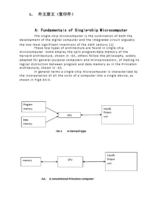
1、 外文原文(复印件)A: Fundamentals of Single-chip MicrocomputerT h e sin gle -ch ip mi c ro co m p u t e r is t h e cu lm in at io n of b ot h t h e d e ve lo p me nt of t h e d ig ita l co m p u t e r a n d t h e i nte g rated c ircu it a rgu ab l y t h e to w mo st s ign if i cant i nve nt i o n s of t h e 20t h c e nt u ry [1].T h ese to w t yp e s of arch ite ct u re are fo u n d in s in gle -ch ip m i cro co m p u te r. S o m e e mp l oy t h e sp l it p ro gra m /d at a m e m o r y of t h e H a r va rd arch ite ct u re , s h o wn in -5A , ot h e rs fo l lo w t h e p h i lo so p hy, wid e l y ad a p ted fo r ge n e ral -p u rp o se co m p u te rs an d m i cro p ro ce ss o rs , of m a kin g n o l o g i ca l d i st in ct i o n b et we e n p ro gra m an d d ata m e m o r y as in t h e P rin c eto n a rch ite ct u re , sh o wn in -5A.In ge n e ra l te r m s a s in g le -ch ip m ic ro co m p u t e r is ch a ra cte r ized b y t h e in co r p o rat io n of all t h e u n its of a co mp u te r into a s in gle d e vi ce , as s h o w n in F i g3-5A-3.-5A-1A Harvard type-5A. A conventional Princeton computerProgrammemory Datamemory CPU Input& Output unitmemoryCPU Input& Output unitResetInterruptsPowerFig3-5A-3. Principal features of a microcomputerRead only memory (ROM).RO M is u su a l l y fo r t h e p e r m an e nt , n o n -vo lat i le sto rage of an ap p l i cat io n s p ro g ram .M a ny m i c ro co m p u te rs a n d m i cro co nt ro l le rs are inte n d ed fo r h i gh -vo lu m e ap p l i cat io n s a n d h e n ce t h e e co n o m i cal man u fa c t u re of t h e d e vi ces re q u ires t h at t h e co nt e nts of t h e p ro gra m me mo r y b e co mm i ed p e r m a n e nt l y d u r in g t h e m a n u fa ct u re of c h ip s . C lea rl y, t h i s imp l ies a r i go ro u s ap p ro a ch to ROM co d e d e ve lo p m e nt s in ce ch an ges can n o t b e mad e af te r m an u fa ct u re .T h i s d e ve l o p m e nt p ro ces s m ay i nvo l ve e mu l at i o n u sin g a so p h ist icated d e ve lo p m e nt syste m wit h a h ard wa re e mu l at i o n capab i l it y as we ll as t h e u s e of p o we rf u l sof t war e to o l s.So m e m an u fa ct u re rs p ro vi d e ad d it i o n a l ROM o p t io n s b y in clu d in g in t h e i r ran ge d e v ic es w it h (o r inte n d ed fo r u s e wit h ) u se r p ro g ram m a b le m e mo r y. T h e s im p lest of t h e se i s u su a l l y d e v i ce wh i ch can o p e rat e in a m i cro p ro ce s so r mo d e b y u s in g s o m e of t h e in p u t /o u t p u t l in es as an ad d res s a n d d ata b u s fo r a cc es sin g exte rn a l m e m o r y. T h is t yp e o f d e vi ce can b e h ave f u n ct i o n al l y as t h e s in gle ch ip m i cro co m p u t e r f ro m wh i ch it i s d e ri ved a lb e it wit h re st r icted I/O an d a m o d if ied exte rn a l c ircu it. T h e u s e of t h e se RO M le ss d e vi ces i s co mmo n e ve n in p ro d u ct io n circu i ts wh e re t h e vo lu m e d o e s n ot ju st if y t h e d e ve lo p m e nt co sts of cu sto m o n -ch ip ROM [2];t h e re ca n st i ll b e a si gn if i cant sav in g in I/O an d o t h e r ch ip s co m pared to a External Timing components System clock Timer/ Counter Serial I/O Prarallel I/O RAM ROMCPUco nve nt io n al m i c ro p ro ces so r b ased circ u it. M o re exa ct re p l a ce m e nt fo rRO M d e v ice s can b e o b tain ed in t h e fo rm of va ria nts w it h 'p i g g y-b a c k'E P ROM(E rasab le p ro gramm ab le ROM )s o cket s o r d e v ice s w it h E P ROMin stead of ROM 。
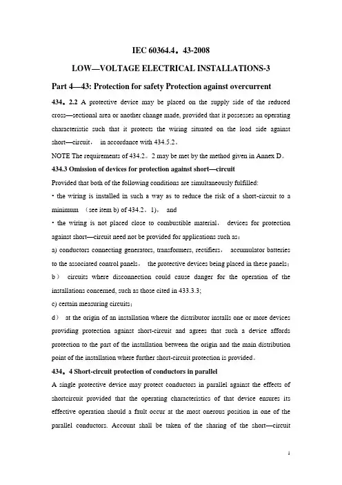
IEC 60364.4。
43-2008LOW—VOLTAGE ELECTRICAL INSTALLATIONS-3Part 4—43: Protection for safety Protection against overcurrent434。
2.2 A protective device may be placed on the supply side of the reduced cross—sectional area or another change made, provided that it possesses an operating characteristic such that it protects the wiring situated on the load side against short—circuit,in accordance with 434.5.2。
NOTE The requirements of 434.2。
2 may be met by the method given in Annex D。
434.3 Omission of devices for protection against short—circuitProvided that both of the following conditions are simultaneously fulfilled:• the wiring is installed in such a way as to reduce the risk of a short-circuit to a minimum (see item b) of 434.2。
1),and• the wiring is not placed close to combustible material,devices for protection against short—circuit need not be provided for applications such as:a) conductors connecting generators, transformers, rectifiers,accumulator batteries to the associated control panels,the protective devices being placed in these panels;b)circuits where disconnection could cause danger for the operation of the installations concerned, such as those cited in 433.3.3;c) certain measuring circuits;d)at the origin of an installation where the distributor installs one or more devices providing protection against short-circuit and agrees that such a device affords protection to the part of the installation between the origin and the main distribution point of the installation where further short-circuit protection is provided。
电气工程的外文文献(及翻译)文献一:Electric power consumption prediction model based on grey theory optimized by genetic algorithms本文介绍了一种基于混合灰色理论与遗传算法优化的电力消耗预测模型。
该模型使用时间序列数据来建立模型,并使用灰色理论来解决数据的不确定性问题。
通过遗传算法的优化,模型能够更好地预测电力消耗,并取得了优异的预测结果。
此模型可以在大规模电力网络中使用,并具有较高的可行性和可靠性。
文献二:Intelligent control for energy-efficient operation of electric motors本文研究了一种智能控制方法,用于电动机的节能运行。
该方法提供了一种更高效的控制策略,使电动机能够在不同负载条件下以较低的功率运行。
该智能控制使用模糊逻辑方法来确定最佳的控制参数,并使用遗传算法来优化参数。
实验结果表明,该智能控制方法可以显著降低电动机的能耗,节省电能。
文献三:Fault diagnosis system for power transformers based on dissolved gas analysis本文介绍了一种基于溶解气体分析的电力变压器故障诊断系统。
通过对变压器油中的气体样品进行分析,可以检测和诊断变压器内部存在的故障类型。
该系统使用人工神经网络模型来对气体分析数据进行处理和分类。
实验结果表明,该系统可以准确地检测和诊断变压器的故障,并有助于实现有效的维护和管理。
文献四:Power quality improvement using series active filter based on iterative learning control technique本文研究了一种基于迭代研究控制技术的串联有源滤波器用于电能质量改善的方法。
Protection relayMicrocomuter-based RlayingA newer development in the of power system protection is the of computers (usually microcomputers) for relaying. Although computers provide the same protection as that supplied by conventional relays, there are some advantages to the use of computer-based relaying. The logic capability and application expansion possibilities for computer-based relaying is much greater than for electromechanical devices. Computer-based relaying samples the values of the current, voltage, and other items covered in the protection scheme several times a second, and by use of A/D converters, change these analog values to digital form and then send them to the computer. In the event of a fault, the computer can calculate the fault’s current values and characteristics, and settings can be changed merely by reprogramming. Computer-based relaying are also capable of locating faults, which has been one of the most popular features in their application. In addition, self-checking features can be built in and sequence of events information can be downloaded to remote computers for fast analysis of relaying operations. Computer-based relying system consists of subsystems with well defined functions. Although a specific subsystem may be different in some of its details, these subsystems are most likely to be incorporated in its design in some form. The block diagram in Figure 13-1 shows the principal subsystems of a computer-based relaying. The processor is the center of its organization. It is responsible for the execution of relaying programs, maintenance of various timing functions, and communicating with its peripheral equipment. Several types of memories are shown in Figure 13-1─each of them serves a specific need. The Random Access Memory (RAM) holds the input sample data as they are brought in and processed. The Read Only Memory (ROM) or Programmable Read Only Memory (PROM) is used to store the programs permanently. In some cases the programs may execute directly form the ROM if its read time is short enough. If this is not the case, the programs must be copied form the ROM into the RAM during an initialization stage, and then the real-time execution would take place form the RAM. The Erasable PROM (EPROM) is needed for storing certain parameters (such as the relaying settings) which may be changed form time to time, but once it is set it must remain fixed even if the power supply to the computer is interrupted. The relaying inputs are currents and voltages─or, to a lesser extent─digital signals indicating contact status. The analog signals must be converted to voltage signals suitable for conversion to digital form. The current and voltage signals obtained form current and voltage transformer secondary windings must be restricted to a full scale value of ±10 volts. The current inputs must be converted to voltages by resistive shunts. As the normal current transformer secondary currents may be as hundreds of amperes, shunts of resistance of a few milliohms are needed to produce the desired voltage for Analog to Digital Converter (ADC). An alternative arrangement would be to use an auxiliary current transformer to reduce the current to lower level. An auxiliary current transformer serves another function: that of providing electrical isolation between the min CT secondary and the computer input system. Since the digital computer can be programmed to perform several functions as long as it has the input and output signals needed for those functions. It is simple matter to the relaying computer to do many other substation tasks, for example, measuring and monitoring flows and voltages in transformers and transmission lines, controlling the opening and closing of circuit breakers and switches, providing backup for other devices that have failed, are functions that can be taken over by the relaying computer. With the programability and communication capability, the computer-based relaying offers yet another possible advantage that is not easily realizable in a conventional system. This is the ability to change the relay characteristics (settings) as the system conditions warrant it. With reasonable prospects of having affordable computer-based relaying which can be dedicated to single protection function, attention soon turned to the opportunities offered by computer-based relaying to integrate them into a substation, perhaps even a system-wide network. Integrated computer systems for substations which handle relaying, monitoring, and control tasks offer novel opportunities for improving overall system performance.Computer relaying The electric power industry has been one of the earliest users of the digital computer as a fundamental aid in the various design and analysis aspects of its activity. Computer-based systems have evolved to perform such complex tasks as generation control, economic dispatch (treated in chapter 11)and load-flow analysis for planning and operation , to name just a few application areas. research efforts directed at the prospect using digital computers to perform the tasks involved in power system protection date back to the mien-sixties and were motivated by the emergence of process-control computers a great deal of research is going on in this field, which is now referred to as computer relaying. Up to the early 1980s there had been no commercially availability protection systems offering digital computer-based relays. However, the availability of microprocessor technology has provided an impetus to computer relaying.*Microprocessors used as a replace*and solid state relays non provide a number of advantages while meeting the basic protection philosophy requirement of decentralization. There are many perceived benefits of a digital relaying system: 1. Economics: with the steady decrease in cost of digital hardware, coupled with the increase in cost of conventional relaying. It seems reasonable to assume that computer relaying is an attractive alternative. Software development cost can be expected to be evened out by utilizing economies of scale in producing microprocessors dedicated to basic relaying tasks. 2. Reliability: a digital system is continuously active providing a high level of a self-diagnosis to detect accidental failures within the digital relaying system. 3. Flexibility: revisions or modifications made necessary by changing operational conditions can be accommodated by utilizing the programmability features of a digital system. This would lead to reduced inventories of parts for repair and maintenance purposes 4. System interaction: the availability of digital hardware that monitors continuously the system performance at remote substations can enhance the level of information available to the control center. Post fault analysis of transient data can be performed on the basis of system variables monitored by the digital relay and recorded by the peripherals.The main elements of a digital computer-based relay are indicated in Figure 9-59. The input signals to the relay are analog (continuous) and digital power system variables. The digital inputs are of the order of five to ten and include status changes (on-off) of contacts and changes in voltage levels in a circuit. The analog signals are the 60-Hz currents and voltages. The number of analog signals needed depends on the relay function but is in the range of 3 to 30 in all cases. The analog signals are scaled down (attenuated) to acceptable computer input levels (10 volts maximum) and then converted to digital (discrete) form through analog/digital converters (ADC). These functions are performed in the block labeled “Analog Input Subsystem.” The digital output of the relay is available through the computer’s parallel output port, five-to-ten digital outputs are sufficient for most applications. The analog signals are sampled at a rate between 210 Hz to about 2000 Hz. The sampled signals are entered into the scratch pad (RAM) and are storedin a secondary data file for historical recording. A digital filter removes noise effects from the sampled signals. The relay logic program determines the functional operation of the relay and uses the filtered sampled signals to arrive at a trip or no trip decision which is then communicated to the system. The heart of the relay logic program is a relaying algorithm that is designed to perform the intended relay function such as over currents detection, differential protection, or distance protection, etc. It is not our intention in this introductory text to purse this involved in a relaying algorithm, we discuss next one idea for peak current detection that is the function of a digital over current relay.。
毕业论文(设计)英文翻译论文题目:电力系统的特殊保护方案系部名称:专业班级:学生姓名:学号:指导教师:教师职称:年月日电力系统的特殊保护方案Michal VARGONČÍK, Michal KOLCUN电气工程与信息学院,电力工程系科希策技术大学,Mäsiarska 74041 20科希策,电话.055/602 3650,电子邮件:Michal.Vargoncik @ tuke.sk 电气工程与信息学院,主管电力工程的科希策技术大学Mäsiarska 74041 20科希策,电话.055/602 3650,电子邮件:Michal.Kolcun @ tuke.sk摘要:这份报告初步研究,针对SPS(系统保护计划设计) 具有以下特点:1)广泛的途径;2)系统的广泛性对一个或多个危险的现象有缓解能力(如电压不稳,频率不稳定等);3)紧急保护功能(由SCADA / EMS系统提供预防性保护);4)执行控制,不仅监督电力系统行为变化的影响,并控制输入(减载负荷等); 5 )综合公用事业。
这份报告简要总结可利用的信息在该地区的SPS控制器。
它是根据科学文献(会议论文集,期刊调查),部分作者的个人经验(公用事业和研发工作会议在这方面的代表)与重点上述列出的功能。
本报告的结构如下。
第一章简单介绍。
第二章定义问题和概述近期内的一些基本问题。
第三章分为几个电力系统的特殊保护方案部分。
每部分集中一个主要的不稳定现象,不稳定原则予以描述,采取相应的对策予以概述- 研究相应的事业和学术环境,强调最终结果。
第四章是结论。
关键词:不稳定、保护、故障、方案。
1.简介:在这篇文章中介绍了危险的电力系统不稳定地现象和定义,发展的历史背景;以及特别保护这种情况的简要分析,和现有安装的特点,SPS设计的主要准则。
2.广域系统:简称SPS是广域系统经常出现的术语。
广域系统有平台服务的各种用途。
它获取的数据(可同步)传达到一个中央位置并处理它们。
电力系统继电保护外文及翻译Power System ProtectionsThe steady-state operation of a power system is frequently disturbed by various faults on electrical equipment. To maintain the proper operation of the power system, an effective, efficient and reliable protection scheme is required. Power system components are designed to operate under normal operating conditions.However, due to any reason, say a fault, there is an abnormality, it is necessary that there should be a device which senses these abnormal conditions and if so, the element or component where such an abnormality has taken place is removed, i.e. deleted from the rest of the system as soon as possible. This is necessary because the power system component can never be designed to withstand the worst possible conditions due to the fact that this will make the whole system highly uneconomical. And therefore, if such an abnormality takes place in any element or component of the power system network, it is desirable that the affected element/component is removed from the rest of the system reliably and quickly in order to restore power in the remaining system under the normal condition as soon as possible.The protection scheme includes both the protective relays and switching circuits, i.e. circuit breakers. The protective relay which functions as a brain is a very important component. The protective relay is a sensing device, which senses the fault, determines its location and then sends command to the proper circuit breaker by closing its trip coil. The circuit breaker after getting command from the protective relay disconnects only the faulted element. this is why the protective relay must be reliable, maintainable and fast in operation.In early days, there used to be electromechanical relay of induction disk-type.However, very soon the disk was replaced by inverted cup, i.e.hollow cylinder and the new relay obtained was known as an induction cup or induction cylinder relay. This relay, which is still in use, possesses several important features such as higher speed; higher torque for a given power input an more uniform torque.However, with the advent of electronic tubes, electronic relays having distinct features were developed during 1940s. With the discovery of solid state components during 1950s, static relays with numerous advantages were developed. The use of digital computers for protective relaying purposes has been engaging the attention of research and practicing engineers since layer 1960s and 1980s. Now, the microprocessor/mini computer-based relaying scheme, because of its numerous advantages such as self –checking feature and flexibility, has been widely used in power system all over the world.The overall system protection is divided into following sections: (i)Generator protection,(ii)Transformer protection,(iii)Bus protection,(iv)Feederprotection,(v)Transmission line protection.Basic Requirements to Protective RelaysAny protection scheme, which i.e. required to safeguard the power system components against abnormal conditions such as faults, consists basically of two elements(i)Protective relay and (ii) Circuit breaker .The protective relay which is primarily the brain behind the whole scheme plays a very important role. Therefore proper care should be taken in selecting an appropriate protective relay which is reliable, efficient and fast in operation. The protective relay must satisfy the following requirements:⑴ since faults on a well designed and healthy system are normally rare, therelays are called upon to operate only occasionally. This means that therelaying scheme is normally idle and must operate whenever fault occurs. Inother words, it must be reliable.⑵ Since the reliability partly depends upon the maintenance, the relay mustbe easily maintainable.⑶ The palpation of the relay can be in two ways. One is the failure to operatein case a fault occurs an second is the relay operation when there is no fault.As a matter of fact, relay must operate if there is a fault and must notoperate if there is no fault.⑷Relaying scheme must be sensitive enough to distinguish between normaland the faulty system.Protective RelaysThe function of the protective relay is to sense the fault and energize the tripcoil of the circuit breaker. The following types of the protective relays are usedfor the apparatus such as synchronous machines, bus bar, transformer and theother apparatus and transmission line protection.(1) Over current relays,(2) Under voltage relays,(3) Under frequency relays,(4) Directional relays,(5) Thermal relays,(6) Phase sequence relays such as(i)negative sequence relays and, (ii)zerosequence relays,(7) Differential relays and percentage differential relays,(8) Distance relays such as (I)plane impedance relays,(ii)angle impedance relay,i.e. Ohm or reactance relays,(iii)angle admittance relays,i.e. Mho relaysand ,(iv)offset and restricted relays,(9)Pilot relays such as (i) wire pilot relays,(ii)carrier channel pilotrelays,(iii)microwave pilot relays. There are different types of the relayingscheme based on construction. They are:(i)electromechanicaltype,(ii)thermal relays,(iii) transduction relays,(iv)rectifier bridgerelay,(v)electronic relays,(vi)digital relaying schemes.电力系统继电保护电力系统的稳态运行经常会因各种电力设备配故障原因而被扰乱。
电力系统继电保护中英文对照表中文词汇英文词汇电力系统Power system继电保护Relay protection保护装置Protective device故障Fault故障电流Fault current故障检测Fault detection故障分类Fault classification故障定位Fault location故障记录器Fault recorder过电压保护Overvoltage protection过电流保护Overcurrent protection地电流保护Earth current protection短路Short circuit短路电流Short circuit current瞬时值Instantaneous value时限值Time limit value跳闸Tripping启动电流Starting current感应式电流互感器Inductive current transformer 压板式电流互感器Plate-type current transformer 合闸Closing开关刀闸Switch disconnector接地刀闸Ground disconnector电流互感器Current transformer功率互感器Power transformer电压互感器Voltage transformer电流差动保护Current differential protection 电压差动保护Voltage differential protection 闭锁Blocking重保Backup protection保护跳闸Protection tripping故障保护Fault protection过零保护Zero-crossing protection过频保护Over-frequency protection沉侵保护Inrush protection远方保护Remote protection就地保护Local protection瞬变保护Transient protection空气开关Air switch隔离开关Isolation switch封闭开关Enclosed switch电力系统自动化Power system automation 故障指示灯Fault indicator电源Power supply接线Wiring电流Current电压Voltage功率Power频率Frequency相位Phase直流Direct current交流Alternating current以上是电力系统继电保护中英文对照表,希望对您有所帮助。
1 Directional protection方向保护2 Distance protection距离保护3 Over current protection过流保护4 Pilot protection高频保护5 Differential protection差动保护6 Rotor earth-fault protection 转子接地保护7 Stator earth-fault protection 定子接地保护8 Over fluxing protection过励磁保护9 Back-up protection后备保护11 Sequential tripping顺序跳闸12 Start up/Pick up起动13 Breaker断路器14 Disconnecting switch隔离开关15 Current transformer电流互感器16 Potential transformer电压互感器17 Dead zone/Blind spot死区18 Vibration/Oscillation振荡19 Reliability可靠性20 Sensitivity灵敏性21 Speed速动性22 Selectivity选择性23 Step-type distance relay分段距离继电器24 Time delay延时25 Escapement/interlock/blocking 闭锁26 Incorrect tripping误动27 Phase to phase fault相间故障28 Earth fault接地故障29 Through- fault穿越故障30 Permanent fault永久性故障31 Temporary fault瞬时性故障32 Overload过负荷34 Contact multiplying relay触点多路式继电器35 Timer relay时间继电器40 Ground fault relay接地故障继电器41 Recloser重合闸42 Zero-sequence protection零序保护43 Soft strap软压板44 Hard strap硬压板45 High resistance高阻46 Second harmonic escapement 二次谐波制动47 CT line-breakCT断线48 PT line-breakPT断线49 Secondary circuit二次回路50 AC circuit breaker交流开关电路51 AC directional over current relay 交流方向过流继电器52 Breaker point wrench开关把手53 Breaker trip coil断路器跳闸线圈54 Bus bar母线; 导电条55 Bus bar current transformer母线电流变压器56Bus bar disconnecting switch分段母线隔离开关57Bus compartment母线室; 汇流条隔离室58Bus duct母线槽; 母线管道59Bus hub总线插座60Bus line汇流线61Bus insulator母线绝缘器62Bus request cycle总线请求周期63Bus reactor母线电抗器64Bus protection母线保护65Bus rings集电环66Bus rod汇流母线67Bus section reactor分段电抗器68Bus structure母线支架; 总线结构69Bus tie switch母线联络开关70Bus-bar chamber母线箱71Bus-bar fault母线故障72Bus-bar insulator母线绝缘子73Busbar sectionalizing switch 母线分段开关74Current attenuation电流衰减75Current actuated leakage protector电流起动型漏电保护器76Current balance type current differential relay电流平衡式差动电流继电器;差动平衡式电流继电器77Current changer换流器78Current compensational ground distance relay电流补偿式接地远距继电器79Current consumption电流消耗80Coil adjuster线圈调节器81Coil curl线圈82Coil current线圈电流83Coil end leakage reactance线圈端漏电抗84Coil inductance线圈电感85Current transformer phase angle电流互感器相角86Distance relay; impedance relay阻抗继电器87Power rheostat电力变阻器88Electrically operated valve电动阀门89Electrical governing system电力调速系统90Field application relay励磁继电器; 激励继电器91High tension electrical porcelain insulator 高压电瓷绝缘子92Option board任选板; 选配电路板; 选择板93Oscillator coil振荡线圈94Over-V oltage relay过压继电器95Power factor relay功率因素继电器96Protection against overpressure超压防护97Protection against unsymmetrical load 不对称负载保护装置98Protection device保护设备; 防护设备99Protection reactor保护电抗器100Protection screen保护屏101Protection switch保护开关102Insulator cap绝缘子帽; 绝缘子帽103Insulator chain绝缘子串; 绝缘子串104Insulator arc-over绝缘子闪络; 绝缘子闪络105Insulator arcing horn绝缘子角形避雷器; 绝缘子角形避雷器106Insulator bracket绝缘子托架; 绝缘子托架107Impedance compensator阻抗补偿器108 Resistance grounded neutral system 中心点电阻接地方式109 Reactance bond电抗耦合; 接合扼流圈110 Reactance of armature reaction电枢反应电抗111 Under-Voltage relay欠压继电器112 V oltage differential relay电压差动继电器114 Relay must-operate value继电器保证启动值115 Relay act trip继电器操作跳闸116 Relay overrun继电器超限运行117 Longitudinal differential protection纵联差动保护118 Phase-angle of voltage transformer电压互感器的相角差119 Zero-sequence current/residual current 零序电流120 Residual current relay零序电流继电器121 Bus bar protection/bus protection母线保护122 Breaker contact point断路器触点123 Cut-off push断路器按钮124 Gaseous shield瓦斯保护装置125 Neutral-point earthing中性点接地126 Internal fault内部故障127 Auxiliary contacts辅助触点128 Neutral auto-transformer中性点接地自耦变压器129 Fuse box/fusible cutout熔断器130 Pulse relay/surge relay冲击继电器旅长2005131 Auxiliary relay/intermediate relay中间继电器132 Common-mode voltage共模电压133 Impedance mismatch阻抗失配134 Intermittent fillet weld间断角缝焊接135 Loss of synchronism protection失步保护136 Closing coil合闸线圈137 Electro polarized relay极化继电器138 Power direction relay功率方向继电器139 Direct-to-ground capacity对地电容140 Shunt running潜动141 Trip/opening跳闸142 Trip switch跳闸开关143 Receiver machine收信机144 High-frequency direction finder 高频测向器145 Capacity charge电容充电146 time over-current时限过电流148 Surge guard冲击防护149 Oscillatory surge振荡冲击150 Fail safe interlock五防装置151 Differential motion差动152 Capacitive current电容电流154 Time delay延时156 Normal inverse反时限157 Definite time定时限158 Multi-zone relay分段限时继电器159 Fail-safe unit五防161 Unbalance current不平衡电流162 Blocking autorecloser 闭锁重合闸163 Primary protection主保护164 Tap分接头165 YC (telemetering)遥测167 Fault clearing time故障切除时间168 Critical clearing time 极限切除时间169 Switch station开关站170 Traveling wave行波171 Protection feature保护特性172 Fault phase selector故障选线元件173 Fault type故障类型174 Inrush励磁涌流175 Ratio restrain比率制动176 Laplace and Fourier transforms 拉氏和傅利叶变换177 Short circuit calculations短路计算178 Load flow calculations潮流计算179 Oscillatory reactivity perturbation 振荡反应性扰动180 Quasi-steady state准稳态181 Automatic quasi-synchronization 自动准同步182 Protective relaying equipment继电保护装置183 AC directional overcurrent relay 交流方向过流继电器184 AC reclosing relay交流重合闸继电器185 Annunciator relay信号继电器188 Carrier or pilot-wire receiver relay载波或导引线接受继电器189 Current-limiting relay限流继电器190 Definite time relay定时限继电器192 Lockout relay闭锁继电器;保持继电器;出口继电器193 Micro-processor based protective relay 微机继电保护194 V oltage -controlled overcurrent relay 电压控制过电流继电器196 Fault diagnosis故障诊断197 Back-up protection后备保护198 Overhead line架空线199 High voltage line高压线路200 Underground cable埋地电缆201 Circuit breaker断路器202 Brushless excitation无刷励磁203 Interlock闭锁204 Trigger触发器205 Winding-to-winding insulation绕组间的绝缘206 Porcelain insulator瓷绝缘子207 Tie line联络线208 Leased line租用线路209 Private line专用线路211 Remote Terminal Unit远程终端设备212 Economic dispatch system经济调度系统213 State estimation状态估计214 Trip by local protection保护跳闸215 Close by local protection保护合闸216 Operational (internal) overvoltage 操作(内部)过电压217 Sampling and holding采样保持218 Synchronized sampling采样同步219 Manipulation操作220 Measuring/Metering unit测量元件221 Locus of measured impedance测量阻抗轨迹222 Differential mode interference差模干扰223 Output (executive) organ出口(执行)元件224 Overcurrent relay with undervoltage supervision低电压起动的过电流保护225 Low impedance busbar protection低阻抗母线保护回复2帖旅长2005228 Half-cycle integral algorithm半周积分算法230 Coordination of relay settings保护的整定配合231 Reach (setting) of protection保护范围(定值)232 Coordination time interval保护配合时间阶段233 Percentage differential relay比率差动继电器234 Electromagnetic relay电磁型继电器236 Instantaneous undervoltage protection with current supervision 电流闭锁的电压速断保护237 Operating equation (criterion)动作方程(判据)238 Operating characteristic动作特性239Harmonic restraining谐波制动241Segregated current differential protection分相电流差动保护242Branch coefficient分支系数243Power line carrier channel (PLC)高频通道245High speed signal acquisition system高速数字信号采集系统246Busbar protection with fixed circuit connection 固定联结式母线保护247Fault recorder故障录波器248Fault phase selection故障选相249Optoelectronic coupler光电耦合器件251Compensating voltage补偿电压252Polarized voltage极化电压253Memory circuit记忆回路254Unblocking signal解除闭锁信号255Power system splitting and reclosing解列重合闸256Connection with 90 degree90度接线257Insulation supervision device绝缘监视258Inrush exciting current of transformer励磁涌流259Two star connection scheme两相星形接线方式260Zero mode component of traveling wave 零模行波261Inverse phase sequence protection逆相序保护262Offset impedance relay偏移特性阻抗继电器263Frequency response频率响应264Activate the breaker trip coil起动断路器跳闸266Permissive under reaching transfer trip scheme 欠范围允许跳闸式267Slight (severe) gas protection轻(重)瓦斯保护268Man-machine interface人机对话接口270Three phase one shot reclosure三相一次重合闸271Out-of-step失步272Accelerating protection for switching onto fault 重合于故障线路加速保护动作275Abrupt signal analysis突变信号分析276Out flowing current外汲电流277False tripping误动279Turn to turn fault,inter turn faults匝间短路280Relay based on incremental quantity增量(突变量)继电器281Vacuum circuit breaker真空开关282Power swing (out of step) blocking振荡(失步)闭锁284Successive approximation type A/D逐次逼进式A/D285Infeed current助增电流286Self reset自动复归287Adaptive segregated directional current differential protection 自适应分相方向纵差保护288Adaptive relay protection自适应继电保护289Pilot protection纵联保护291Angle of maximum sensitivity 最大灵敏角292Out of service退出运行294Waveform波形295Outlet出口296Electromechanical机电的297Magnitude of current电流幅值299Traveling wave signal行波信号300Measurement signal测量信号301Traveling wave relay行波继电器302Transmission line malfunction 输电线路异常运行303Subsystem子系统304Positive sequence impedance 正序阻抗305Negative sequence impedance 负序阻抗306Zero sequence impedance零序阻抗307Digital signal processor数字信号处理器308Frequency sensing频率测量309Cable relay电缆继电器310Under power protection低功率保护311Under voltage protection低电压保护312Transient analysis暂态分析313V oltage sensor电压传感器314Zero-sequence protection零序保护315Zero sequence current transducer 零序电流互感器316Shunt旁路,并联317Series串联,级数318Parallel并联319Saturation饱和320Free-standing独立的,无需支撑物的321Troidal环形的,曲面,螺旋管形322Bushing套管323Magnetizing磁化324Dropout current回动电流325Reactor grounded neutral system 中性点电抗接地系统326Grounding apparatus接地装置327Dual bus双总线328Thyristor晶闸管329Spark gap火花隙330Damping circuit阻尼电路331Discharge放电332Platform平台333Grading等级334Line trap线路陷波器335Field test实地试验337Off-position“断开”位置,“开路”位置338Power-angle功角339Power-angle curve功角特性曲线340Torque-angle转矩角341Symmetrical components 对称分量342Constant常量,恒定343Coupler耦合器345Concussion震动348Filter滤波器349Analogue模拟350Insulator绝缘子351Switch cabinet开关柜352Rated burden\load额定负载353Primary一次侧的354Remote-control apparatus 远距离控制设备355Capacitance电容356Capacitor电容器357Reactance电抗358Inductor电感359Internal resistance内阻360Blow-out coil消弧线圈361Bundle-conductor spacer 分裂导线362Bundle factor分裂系数363Electromotive force电动势364V olt-amphere characteristic伏安特性365Outgoing line引出线366electrolyte电解质368Load characteristic负载特性369Self-induction自感370Mutual-induction互感371Induction coefficient感应系数372Inductance couping电感耦合373Time-invariant时不变的回复3帖4旅长2005端电压375Non-linear characteristics 非线性特性376External characteristics 外特性378Harmonic current正弦电流379Pole-pairs极对数380Quadrature正交381Angular velocity角频率382Magnetic induction磁感应强度385Armature电枢386Peak value(交变量的)最大值387A mutually induced e.m.f互感电动势The applied voltage外施电压389Zero-power-factor零功率因数390The no-load power factor 空载功率因数391Sinusoidal variations正弦变量392A lagging power factor 滞后的功率因数393Equivalent circuit等值电路394Capacitance effect电容效应395Direct axis直轴396Quadrature axis交轴398Concentrated coil集中绕组399Magnetization curve磁化曲线Residual magnetism剩磁401Rated armature current 额定电枢电流402Series excited串励403Self excited自励404Shunt excited并励405spottily excited他励407 Electromagnetic torque 电磁转矩408a retarding torque制动转矩409Rectangular wave矩形波410Synchronous speed同步转速411 Electromagnetic brake 电磁制动synchronous reactance同步电抗413synchronous condenser同步调相机414Load shedding甩负荷415Black-start黑启动417Distribution feeder配电馈线418Commissioning投运419Reactive power compensation 无功补偿器420Continuous rating连续运行的额定值421AI (artificial intelligence)人工智能422Network topology网络拓补424Configuration control组态控制Topological information拓补信息426Black-out area停电区428Adaptive relaying自适应继电保护429Adaptive features自适应特性430Phase comparison relays相位比较继电器431Directional contact方向触点432Protective gap保护间隙433Protective earthing保护接地434Protective earthing; outer insulation 保护绝缘435Protection switch保护开关436Protective cap保护帽Protective panel保护屏柜439Protection device保护设备440Protective casing保护外壳441Catch net; protecting net保护网442Protection system保护系统443Protective link保护线路444Protective ground保护性接地445Protective cover; Protective housing 保护罩446Protection device; Protective gear 保护装置447Protective transformer保护变压器448Alarm relay报警信号继电器Alarm signal;alerting signal报警信号450Admittance relays导纳型继电保护装置451Low-voltage protection低压保护452Under-voltage release低电压跳闸453Under-voltage trip低电压自动跳闸454Under-run低负荷运行455Under-power protection低功率保护456Under-power relay低功率继电器457Under-frequency protection低频保护458Low-frequency high-voltage test 低频高压实验459Low-voltage relay低压继电器Low-voltage release relay 低压释放继电器461Under-frequency protection 低周波保护463Under-impedance relay低阻抗继电器465Conductance relay电导继电器466Motor-field failure relay电动机磁场故障继电器467Dynamoelectric relay电动式继电器468Electric reset relay电复位继电器469Power-transformer relay电力传输继电器471Power system oscillation 电力系统振荡472Electric interlock relay连锁继电器473Current overload电流过载Self-polarizing relay电流极化继电器475Current-balance relay 电流平衡式继电器476Circuit control relay电路控制继电器479Capacitance relay电容继电器480Capacity ground电容接地481V oltage balance relay电压平衡继电器482Circuit control relay电路控制继电器483V oltage responsive relay 电压响应继电器484V oltage selection relay 电压选择继电器485Power failure电源故障486Power-transfer relay电源切换继电器vacuum-tube relay电子管继电器488Ohm relay电阻继电器489Timing relay; timed relay定时继电器490Time pulse relay定时脉冲继电器492Directional over-current relay方向过流继电器493Directional over-current protection 方向过流保护494Directional distance relay方向距离继电器495Directional pilot relaying方向纵联继电保护497Cut-off relay断路继电器498Circuit breaker failure protection 断路器故障保护装置500Open-phase relay断相继电器Earth-leakage protection对地漏电保护502Multiple-reclosing breaker多次重合闸断路器503Multi-ended circuit protection多端线路保护506Multiple earth多重接地507Two-position relay二位置继电器508Generator protection发电机保护509Generator cutout relay发电机断路继电器510Generator protection for negative sequence current 发电机负序电流保护511Transmitting relay发送继电器512Back-spin timer反转时间继电器513Auxiliary relay辅助继电器Negative phase relay负相位继电器515Negative-phase sequence impendence 负相序继电器516Under-load relay负载不足继电器517Back-up over-speed governor附加超速保护装置518Induction cup relay感应杯式继电器520Induction type relay感应式继电器521Induction disc relay感应圆盘式继电器522High sensitive relay高灵敏度继电器回复4帖5旅长2005523High-speed impedance relay 高速阻抗继电器524High-voltage relay高压继电器525Power relay功率继电器527Transition impedance过渡阻抗528Thermal protection过热保护529Temperature limiting relay过热继电器530Overload relay过载继电器531Overload trip过载跳闸532Thermostat relay恒温继电器533Closing relay合闸继电器534Transverse differential protection 横差保护535Transfer of auxiliary supply后备电源切换536Back-up system后备继电保护Delay-action relay缓动继电器538Slow-to release relay缓放继电器539Converter relay换流器继电器540Electromechanical relay机电继电器541Biased differential relaying极化差动继电保护系统542Discontinuous relay鉴别继电器543Transistor relay晶体管继电器544Crystal can relay晶体密闭继电器545Static relay静电继电器546Fast-operate slow-release relay 快动缓释继电器547Fast-release relay快释放继电器Excitation-loss relay失磁继电器553Two-phase short circuit fault 两相短路故障554Two-phase grounding fault 两相接地短路故障556Sensitive polarized relay灵敏极化继电器558Sensitive relay灵敏继电器560Abnormal overload异常过载561Abnormal overvoltage事故过电压562Above earth potential对地电势563Absolute potential绝对电势564AC circuit breaker交流断路器565AC component交流分量AC distribution system 交流配电系统567Air-blast circuit breaker 空气灭弧断路器568Air-blast switch空气吹弧开关569Air brake switch空气制动开关571Air breaker空气断路器572Air-space cable空气绝缘电缆573Alive带电的574All-relay interlocking 全部继电连锁575All-relay selector全继电式选择器578Arc extinguishing coil 灭弧线圈579Arc suppressing reactor 灭弧电抗器Asymmetric load不对称负载581Asymmetric short circuit 不对称短路582Asynchronous reactance 异步电抗583Asynchronous resistance 异步电阻584Biased differential relaying 极化差动继电保护系统585Bi-directional relay双向继电器586Blinker继电器吊牌587Blocking relay连锁继电器589Blowout coil灭弧线圈590Bus hub总线插座591Bus protective relay母线保护继电器Bus section breaker 母线分段断路器593Bus terminal fault母线终端故障594Bus separation母线分离595Bus tie circuit breaker 母线联络继电器596Bypass旁路597Coil factor线圈系数598Compound relay复合电路599Continuous load持续负载600Counting relay计数继电器602Cut-off of supply停止供电603Cut-out relay短路继电器Dash current冲击电流605Data medium数据载体606Data processing数据处理607Data transmission数据传输608Emergency service事故运行609Emergency standby 事故备用611Extinction coil消弧线圈612Extinguishing voltage 消弧线圈613Extra high voltage超高压614Fault line故障线615Fault location故障定位Feedback反馈617Feeder馈电线618Interlock连锁619Intermittent fault间歇故障620Interrupting time断路时间621Negative direction反方向622No-load release无跳闸623Off-peak非峰值的624Operating load运行负载625Orthogonal正交的626Rated primary voltage 一次额定电压Rated secondary volage 二次额定电压628Remote controlled遥控的629Reserve bus备用母线630Rotor转子631Sectionalizer分段断路器632Self-energizing自激的633Sequential tripping顺序跳闸637Surge voltage冲击电压638Sustained overload持续过电压639Symmetrical对称的640Fault component故障分量Wavelet transform小波变换642Object-oriented面向对象643Faults recorder故障录波644Setting calculation整定计算645Topology analysis拓扑分析646Expert system专家系统647Security安全性651Load schedule according to frequency change 按周波减载653Semiconductor, semiconductor diode, transistor 半导体、半导体二级管、三极管654Semi-orthogonal wavelet半正交小波656Saturation, saturation detection, saturation curve 饱和,饱和检测,饱和曲线Relay location保护安装处658Coordination of relay settings保护的整定配合659Coordination time interval保护配合时间阶段660Relay system configuration保护配置661Redundancy of relaying system保护配置的冗余度663Protection devices, protection equipment保护装置664Starting current and returning current of protection device 保护装置的起动电流和返回电流665Alarm报警666Approximation component逼近分量668B sampling functionB样条函数670Transformation matrix变换矩阵。
Protection relayMicrocomuter—based RlayingA newer development in the of power system protection is the of computers (usually microcomputers) for relaying。
Although computers provide the same protection as that supplied by conventional relays, there are some advantages to the use of computer-based relaying. The logic capability and application expansion possibilities for computer—based relaying is much greater than for electromechanical devices。
Computer—based relaying samples the values of the current,voltage, and other items covered in the protection scheme several times a second, and by use of A/D converters, change these analog values to digital form and then send them to the computer。
In the event of a fault, the computer can calculate the fault’s current values and characteristics,and settings can be changed merely by reprogramming。
中文2000字附录:110Kv power supply system relay protection function brief analysisNot only the 110Kv power supply system relay protection function brief analysis electrical power system security and the reliability relate electrical power system itself the movement, similarly relates in the power transmission scope the factories and mines, the enterprise, whether the inhabitant uses electricity normally.Because simultaneously the electrical power system has the strong connectivity, electrical power system interior any barrier all possibly affects the overall system normal operation, thus we must complete the power supply system practically the relay protection question.First, the 11OKV power supply systemGenerally speaking electrical power system including the electricity generation, changes the electricity, the electric transmission, the power distribution and uses electricity and so on five links, between five links restricted mutually, cooperates mutually has facilitated the electrical power system stability together.But in fact, because these five links not always in the identical place, the identical time complete, the electric transmission must surmount the vast area, simultaneously the electrical power system must not carry on the connection with the equipment, thus strengthened its movement environment complexity, causes electrical power system the zero failure rate to guarantee with difficulty.The 110Kv power supply system is in the entire electrical power system important constituent, it whether safe, stable, reliable movement, not only relates the system own movement quality, whether moreover relates in its power transmission scope general user normal prompt using electricity, it the economical normal development and the society is stably taking on the important energy safeguard duty to the power transmission scope in.Therefore the 110KV power supply system design and the movement management must observe national comprehensively the related standard and the standard, as well as correlation area specifically standard standard.In the 110Kv power supply system is containing a subsystems and two subsystems.Two subsystems were opposite in a subsystems are complex, violate the subsystems to include the relay protection installment, the automatic device and the secondary circuit.The relay protection installment is uses for in the power supply system to a subsystems to carry on the surveillance, the survey, the control and the protection, is composed set of special automatic devices by the relay.The reasonable relay protection installment correct establishment to guarantees the 110Kv power supply system the normal operation to have the positive function.Second, the relay protection digs reads and the related principleElectrical power system rapid development to the relay protection to propose unceasingly the new request, the electronic technology, the computer technology and the communication rapid development unceasingly has poured into the new vigor for the relay protection technology development.The relay protection is refers when in the electrical power system electric power part (for example generator, line and so on) or electrical power system itself has occurred the breakdown endangers the electrical power system safe operation, can to the attendant promptly send out thewarning signal, or directly to the circuit breaker which controls sends out the trip order to terminate one kind of automated protection which these events develop, the relay protection equipment can monitor the electrical equipment the normal work situation, and sends out the prompt signal differently according to the normal work situation and the equipment movement maintenance condition, in order to the attendant carries on prompt processing, either carries on the adjustment automatically by the protective device, either continues these to move possibly can cause the accident electrical equipment to excise.Response normal work situation relay protection equipment common belt certain time-lag action.The relay protection principle of work mainly has used in the electrical power system the part has when the short circuit or the unusual situation the electrical quantity (electric current, voltage, power, frequency and so on) change as well as in transformer fuel tank when breakdown occurs the massive gas and the oil stream speed increase or the flowing tubing head pressure intensity increase the higher condition.The electrical power system request provides the safekeeping of security for it to continue the electricity installment to have following performance:(1) reliability. The reliability is refers to the protection to be supposed to move time the body should act reliably.Should not when the movement should reliable not act.The reliability is to the relay protection installment performance most basic request.(2) selectivity. The selectivity is refers first by the breakdown equipment logical 'OR' circuit itself protection excision breakdown, when the breakdown equipment logical 'OR' circuit itself protection or the circuit breaker resist moves, only then allows by the neighboring equipment to protect, the line protection or the circuit breaker malfunction protection excision breakdown.In order to guarantee has in the coordinate request protection and the identical protection has the coordinate request two parts (for example start and trip part or block system and movement part) the selectivity to the neighboring equipment and the line, its sensitivity coefficient and the operating time, should coordinate mutually in the ordinary circumstances.(3) sensitivity. The sensitivity is refers when the equipment logical 'OR' circuit occurs by the extent of protection in the metallicity short circuit, the protective device should have the essential sensitivity coefficient, each kind of protection smallest sensitivity coefficient has the specific stipulation in the regulations.Selectivity and sensitive request, through relay protection installation realization.(4) speed. The speed is refers to the protective device to be supposed to excise the short circuit breakdown as soon as possible, its date enhances the system stability, reduces the breakdown equipment and the line damage degree, reduces the breakdown to affect the scope, enhances automatic switches on again with the emergency power supply or the emergency apparatus automatic investment effect and so on.Third, relay protection in 11OKV power supply system Chen Ai function1. The guarantee continues the electricity system the reliability is plays the relay protection installment role the premise. Continues the electricity system the reliability is plays the relay protection installment role the premise.Generally speaking the relay protection reliability mainly by the disposition reasonable, the quality and the technical performance fine relay protection installment as well as the normal movement maintenance and the management guaranteed.2. Relay protection in electrical power system safe operation function. The relay protection mainly has following two points in the electrical power system safe operation function:(1) safeguard electrical power system security.When is protected when the electrical power system part breaks down, should rapidly accurately for be separated from the breakdown part recent circuit breaker by this part relay protection equipment to send out the trip order, causes the breakdown part to interrupt promptly from the electrical power system, by maximum limit reduces to the electrical power system part itself damage, reduces to the electrical power system safe power supply influence, and satisfies the electrical power system certain specific requests (for example maintenance electrical power system transition condition stable and so on).(2)pair of electrical power system normal work carries on the prompt.Responded the electrical equipment the normal work situation, (whether there is and different e.g. frequent attendant) does send out the signal according to the normal work situation and the equipment movement maintenance condition, in order to the attendant carries on processing, either carries on the adjustment automatically by the equipment, either continues these to move can cause the accident electrical equipment to excise.Response normal work situation relay protection installment permission belt certain time-lag action.(3) pair of electrical power system movement carries on the monitoring.The relay protection is not merely an accident processing and the response installment, simultaneously also is monitors the electrical power system normal operation the installment.The relay protection is the electrical power system safe normal operation important safeguard, at present oneself after obtained the widespread application, along with the science and technology unceasing progress, the relay protection technology presents day by day to the microcomputer, the network, the intellectualization, protects, the control, the survey and the data communication integration development tendency.110KV供电系统继电保护作用浅析电力系统的安全性和可靠性不仅关系到电力系统本身的运行,同样关系到送电范围内的厂矿、企业、居民能否正常用电。
3-电气工程及其自动化专业外文文献英文文献外文翻译1、外文原文(复印件)A: Fundamentals of Single-chip MicrocomputerThe single-chip microcomputer is the culmination of both the development of the digital computer and the integrated circuit arguably the tow most significant inventions of the 20th century [1].These tow types of architecture are found in single-chip microcomputer. Some employ the split program/data memory of the Harvard architecture, shown in Fig.3-5A-1, others follow the philosophy, widely adapted for general-purpose computers and microprocessors, of making no logical distinction between program and data memory as in the Princeton architecture, shown in Fig.3-5A-2.In general terms a single-chip microcomputer is characterized by the incorporation of all the units of a computer into a single device, as shown in Fig3-5A-3.ProgramInput& memoryOutputCPU unitDatamemoryFig.3-5A-1 A Harvard typeInput&Output CPU memoryunitFig.3-5A-2. A conventional Princeton computerExternal Timer/ System Timing Counter clock componentsSerial I/OReset ROMPrarallelI/OInterrupts RAMCPUPowerFig3-5A-3. Principal features of a microcomputerRead only memory (ROM).ROM is usually for the permanent,non-volatile storage of an applications program .Many microcomputers and microcontrollers are intended for high-volume applications and hence the economical manufacture of the devices requires that the contents of the program memory be committed permanently during the manufacture of chips . Clearly, this implies a rigorous approach to ROM code development since changes cannot be made after manufacture .This development process may involve emulation using a sophisticated development system with a hardware emulation capability as well as the use of powerful software tools.Some manufacturers provide additional ROM options by including in their range devices with (or intended for use with) user programmablememory. The simplest of these is usually device which can operate in a microprocessor mode by using some of the input/output lines as an address and data bus for accessing external memory. This type of device can behave functionally as the single chip microcomputer from which itis derived albeit with restricted I/O and a modified external circuit. The use of these ROMlessdevices is common even in production circuits where the volume does not justify the development costs of custom on-chip ROM[2];there canstill be a significant saving in I/O and other chips compared to a conventional microprocessor based circuit. More exact replacement for ROM devices can be obtained in the form of variants with 'piggy-back' EPROM(Erasable programmable ROM )sockets or devices with EPROM instead of ROM 。
电力系统电力系统介绍随着电力工业的增长,与用于生成和处理当今大规模电能消费的电力生产、传输、分配系统相关的经济、工程问题也随之增多。
这些系统构成了一个完整的电力系统。
应该着重提到的是生成电能的工业,它与众不同之处在于其产品应按顾客要求即需即用。
生成电的能源以煤、石油,或水库和湖泊中水的形式储存起来,以备将来所有需。
但这并不会降低用户对发电机容量的需求。
显然,对电力系统而言服务的连续性至关重要。
没有哪种服务能完全避免可能出现的失误,而系统的成本明显依赖于其稳定性。
因此,必须在稳定性与成本之间找到平衡点,而最终的选择应是负载大小、特点、可能出现中断的原因、用户要求等的综合体现。
然而,网络可靠性的增加是通过应用一定数量的生成单元和在发电站港湾各分区间以及在国内、国际电网传输线路中使用自动断路器得以实现的。
事实上大型系统包括众多的发电站和由高容量传输线路连接的负载。
这样,在不中断总体服务的前提下可以停止单个发电单元或一套输电线路的运作。
当今生成和传输电力最普遍的系统是三相系统。
相对于其他交流系统而言,它具有简便、节能的优点。
尤其是在特定导体间电压、传输功率、传输距离和线耗的情况下,三相系统所需铜或铝仅为单相系统的75%。
三相系统另一个重要优点是三相电机比单相电机效率更高。
大规模电力生产的能源有:1.从常规燃料(煤、石油或天然气)、城市废料燃烧或核燃料应用中得到的蒸汽;2.水;3.石油中的柴油动力。
其他可能的能源有太阳能、风能、潮汐能等,但没有一种超越了试点发电站阶段。
在大型蒸汽发电站中,蒸汽中的热能通过涡轮轮转换为功。
涡轮必须包括安装在轴承上并封闭于汽缸中的轴或转子。
转子由汽缸四周喷嘴喷射出的蒸汽流带动而平衡地转动。
蒸汽流撞击轴上的叶片。
中央电站采用冷凝涡轮,即蒸汽在离开涡轮后会通过一冷凝器。
冷凝器通过其导管中大量冷水的循环来达到冷凝的效果,从而提高蒸汽的膨胀率、后继效率及涡轮的输出功率。
而涡轮则直接与大型发电机相连。
Protection of Electrical SystemAll electrical systems have the common purpose of providing electrical energy to the utilization equipment as safely and reliably as is economically feasible .The utilization equipment then converts the electrical energy to other forms, such as mechanical, light, and heat energy .The design of the electrical energy to transmit the electrical energy to the utilization equipment must focus on two basic requirements. First, the system must be adequate to deliver to each piece of equipment the necessary energy on a continuous basis under normal conditions. Second, the system must be designed to minimize power outages and damage in the event that abnormal conditions occur on the system. The following is a list of abnormal conditions that can occur on a system and for which corrective action should be taken:1.Overloads2.Short circuits3.Under voltage4.Single phasing of three phase systems5.Over-voltages and transient surges6.Incorrect synchronizing of frequencies7.Incorrect phase sequence8.Reverse power flowNext in order of priorities is the desirability of keeping damage to the electrical equipment to the absolute minimum so that normal operation can resume as quickly as possible .Finally it makes economic sense, especially with large system can continue to operate normally .This requirement for the least amount of shutdown of the system involves coordination of the protective devices.The protective device has two major functions:(1) to detect an abnormal condition on that portion of the system that it is protecting and (2) to automatically and safely disconnect the faulted portion from the balance of the system .Protective devices such as fuses and most low-voltage circuit breakers combine both the detection unit and the disconnecting means in the one unit. Other types of protectivedevices separate the two functions. For example, medium-and high-voltage circuit breakers normally only perform the disconnecting function. They must be used in conjunction with separate protective relays that detect the abnormal conditions and then initiate the tripping of the circuit breaker. It must be emphasized again that protective devices cannot prevent faults from occurring on the system, but can only minimize their effects.Protective devices are rated for the following:1.Maximum continuous voltage: This is the maximum voltage that can be continuously applied to the device without eventually causing the insulation to fail.2.Maximum continuous current: This is the maximum load current that the device can carry continuously without the contacts or other current-carrying parts overheating.3.Interrupting rating: This is the maximum current that the device can safely interrupt at the specified voltage.4.Short-time current ratings:(a)Momentary: This is the maximum rms current that the device can withstand with regard to mechanical stressing. The maximum stressing occur one half-cycle after the fault starts. This rating is necessary to ensure that the device is not physically damaged before it can operate to disconnect the faulted part of the system.(b) Specified time: This is the maximum rms current that the device can withstand for a specified time 0.5% with regard to thermal stressing .In the case of breakers, it is sometimes necessary under severe short circuits to delay their opening for a very short period of time in order to coordinate with other devices .This rating is necessary to ensure that the breaker is not damaged by heat before it can operate to disconnect the faulted part of the system.Protective RelayingProtective relaying is that area of power system design concerned with minimizing service interruption and limiting damage to equipment when failures occur. The function of protective relaying is to cause the prompt removal of adefective element from a power system .The defective element may have a short circuit or it may be operating in an abnormal manner. Protective relaying systems are designed to detect such failures or abnormal conditions quickly (commensurate with system requirements) and to open a minimum of circuit breakers to isolate the defective element. The effect of quick isolate is threefold: (1) it minimizes or prevents damage to the defective element, thus reducing the time and expense of repairs and permitting quicker restoration of the element to service; (2) it minimizes the power system; and (3) it. maximizes the power that can be transferred on power system. The second and third points are of particular significance because they indicate the important role protective relaying plays in assuring maximum service reliability and in system design. The power that can be transmitted across system without the loss of synchronism is the function of fault clearing times. It is apparent that fast fault clearing times permit a higher power transfer than longer clearing times. High-speed clearing of faults can often provide a means for achieving higher power transfers and thereby defer investment in additional transmission facilities.A protective relaying system is based on detecting fault conditions by continuously monitoring the power system variable such as current, voltage, power, frequency, and impedance. Measuring of currents and voltage is performed by instrument transformers of the potential type (PT) or current type (CT). Instrument transformers feed the measured variables to the relay system, which in return, upon detecting a fault, commands circuit breaker (CB) to disconnect the faulted section of the system.An electric relaying system is divided into several protective zones for generators, transformers, buses, transmission and distribution circuits, and motors. The division is such that zones are given adequate protection while keeping service interruption to a minimum. It is to be noted that each zone is overlapped to avoid unprotected (blind) areas. The connections of current transformers achieve the overlapping. The general philosophy of relay application is divide the power system into zones that can be adequately protected by suitable protective equipment and can be disconnected from the power system in a minimum amount of time and with theleast effect on the remainder of the power system. The protective relaying provided for each zone is divided into two categories: (1) primary relaying and (2) backup relaying. Primary relaying is the first line of defense when failures occur, and is connected to trip only the protective relays will operate to trip all of the breakers within that zone. If a breaker is omitted between two adjacent elements, both elements will be disconnected for a failure in either one. This latter arrangement is illustrated by the unit generator-transformer connection in the power plant. On bulk power generating and transmission systems, primary protection is designed to operate at high speed for all faults. Slower protection may be used in less important system areas but, in general, any system area will benefit by the fastest possible primary relaying.If the fault is not cleared by the primary protection, backup relaying operates to clear the fault from the system. In general, backup relaying disconnects a greater portion of the system to isolate the fault. Backup protection is provided for possible failure in the primary both relay backup as well as breaker backup. Ideally, the backup protection should be arranged so that anything that may cause the primary protection to fail will not also cause failure of the backup protection .Moreover, the backup protection must not operate until the primary protection has been given an opportunity to function. As a result, there is time delay associated with any backup operation. When a short circuit occurs, both the primary and the backup protection start to operate. If the primary protection clears the fault, the backup protection will reset without completing its function. If the fault is not cleared by the primary protection, the backup relaying will time out and trip the necessary breakers to clear the fault from the system.There are two forms of backup protection in common use on power system. They are remote backup and local backup.(1)Remote backup. In remote backup relaying, faults are cleared from thesystem one station away from where the failure has occurred.(2)Local backup. In local backup relaying, faults are cleared locally in thesame station where the failure has occurred. For faults on the protectedline, both the primary and the backup relays will operate to preparetripping the line breaker. Relay backup may be just as fast as the front linerelays. When either of these relays operates to initiate tripping of the linebreaker, it also energizes a timer to start the breaker backup function. Ifthe breaker fails to cleat the fault, the line relays will remain picked up,permitting the timer to time out and trip the necessary other breaker onthe associated bus section.Microcomputer-based RelayingA new development in the field of power system protection is the use of computers (usually microcomputers) for relaying. Although computers provide the same protection as that supplied by conventional relays, there are some advantages to the use of computer-based relaying is much greater than for electromechanical devices. Computer-based relaying samples the values of the current, voltage, and other items covered in the protection scheme several times a second, and by use of A/D converters, change these analog values to digital form and then send them to the computer. In the event of a fault, the computer can calculate the fault’s current values and characteristics, and settings can be changed merely by reprogramming. Computer-based relaying are also capable of locating faults, checking features can be built in and sequence of events information can be downloaded to remote computers for fast analysis of relaying operations.Computer-based relaying system consists of subsystems with well defined functions. Although a specific subsystem may be different in some of its details, these subsystems are most likely to be incorporated in its design in some form. The processor is the center of its organization. It is responsible for the execution of relaying programs, maintenance of various timing functions, and communicating with its peripheral equipment. The Random Access Memory (ROM) or Programmable Read Only Memory (PROM) is used to store the programs permanently. In some cases the programs may execute directly from the ROM if its read time is short enough. If this is not the case, the programs must be copied from the ROM into the PAM during an initialization stage, and then the real-time execution would take placefrom the RAM. The Erasable PROM (EPROM) is needed for storing certain parameters (such as the relaying settings) which may be changed from time to time, but once it is set it must remain fixed even if the power supply to the computer is interrupted.The relaying inputs are currents and voltages -- or, to a lesser extent –digital signals indicating contact status. The analog signals must be converted to voltage signals suitable for conversion to digital form. The current and voltage signals obtained from current and volts. The current inputs must be converted to voltages by resistive shunts. As the normal current transformer secondary currents may be as high as hundreds of amperes, shunts of Digital Converter (ADC). An alternative arrangement would be to use an auxiliary current another function; that of providing electrical isolation between the main CT secondary and the computer input system. Since the digital computer can be programmed to perform several functions as long as it has the input and output signals needed for those functions. It is a simple matter to the relaying computer to do many other substation task, for example , measuring and monitoring flows and voltages in transformers and transmission lines, controlling the opening and closing of circuit breakers and switches, providing backup for other devices that have failed, are all functions that can be taken over by the relaying computer. With the program ability and communication capability, the computer-based relaying computer offers yet another possible advantage that is not easily realizable in a conventional system. This is the ability to change the relay characteristics (settings) as the system conditions warrant it. With reasonable prospects of having affordable computer-based relaying which can be dedicated to a single protection function, attention soon turned to the opportunities offered by computer-based relaying to integrate them into a substation, perhaps even a system-wide network. Integrated computer systems for substations which handle relaying, monitoring, and control tasks offer novel opportunities for improving overall system performance.。