Arduino烧写BootLoader
- 格式:pdf
- 大小:1.25 MB
- 文档页数:5
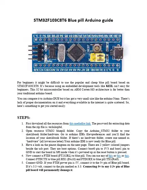
STM32F103C8T6 Blue pill Arduino guideFor beginners it might be difficult to use the popular and cheap blue pill board based on STM32F103C8T6. It’s because using an embedded development tools like KEIL isn’t easy for beginners. This 32 bit microcontroller based on ARM Cortex-M3 architecture is far better than your traditional arduino board.You can compare it to Arduino DUE but it has got a very small size like the arduino Nano. T here’s lack of proper documentation on it and everything available in the internet is quite scattered. So, here’s something to get you started easily.STEPS:1.First download all the resources from this mediafire link. The password for extracting datafrom the zip file is: techshopbd.2.Open resource STM32 bluepill folder. Copy the Arduino_STM32 folder to yoursketchbook folder/hardware. Go to arduino IDEs file>preferences and you’ll find the location of your sketchbook folder. If there’s no hardware folder, create one named as “hardware” (all lowercase letter).Your arduino IDE is now ready for Blue pill.3.Have a look on the pinout diagram on the next page. There are 2 yellow colored jumpersbeside the usb port. They are boot options. Connect boot0 pin to 3V3 and boot1 pin to GND to start the board in SPI mode when it’s power ed up or the reset button is pressed.4.Now connect a FTDI board (FT232RL) to blue pill. You can use any of this or this or this.Connect FTDI TX to blue pill RX1 (PA10) and FTDI RX to blue pill TX1(PA9).5.Connect GND. If your FTDI power pin is 5V, connect it to the 5v pin of Blue pill board.If it’s 3.3 vo lt, connect to the pin marked as 3.3. Connecting 5v to any 3.3v pin of Blue pill board will permanently damage it.6.Connect the FTDI board to your PC using USB port. You must install the FTDI driver toyour PC to use the FTDI board. You’ll find enough resources on the internet on this. FYI, it’s the driver for arduino Nano.7.Close arduino IDE if it’s open. Then open it. Go to Tools>board> Generic STM32F103CSeries. Then go to Tools>Variant>STM32F103C8T6(20k ram, 64k flash). These new options for STM32 will be automatically added to arduino if you’ve performed everything described it step 2 successfully.8.Go to tools> upload method>serial. Then tools>port and select the port of the FTDI.9.Go to tools>board> Boards manager and check if “Arduino SAM Boards (32 bit ARMCortex M3)” is installed or not. If not, select more info and an install button will appear.Install the board definitions. It’s necessary becaus e codes for the Blue pill board uses some files written for Arduino Duo for successful compilation.10.Now open the blink code from File>Examples>Basic>blink. Press the reset button on theBlue pill board and hit upload button on the Arduino IDE. (board built-in LED is on PC13)11.Note that you have to reset the Blue pill board every time you are about to upload code.12.You will find all other Examples for the Blue pill board under Up button beneath toolsoption>hardware>Arduino_STM32.Note that, your code will stop working as soon as you restart or reset the blue pill board. You have to connect boot0 pin to GND using the jumper after uploading code to watch your code working. But you cannot upload code using USAR1 when boot0 is connected to GND. So,1.Every time before uploading code, connect boot0 to 3V3 and press the reset button2.When done with code uploading, connect boot0 to GND.Uploading program directly to flash:If you don’t want to use FTDI to upload code and use the microusb por t of the blue Pill board instead, you have to flash a bootloader inside the STM32F103C8T6. By doing so, you don’t have to connect boot0 pin to 3v3 for uploading code. And there will be no need to press the RESET button every time before uploading a code.1.Download demonstrator gui (STM32 flasher) from this link. You have to create a freeaccount to download. Install the software when downloaded.2.Keep your blue Pill board connected to PC via the FTDI and keep boot0 pin connected to3V3. Press the RESET button.3.Open STMFlashLoader Demo (demonstrator gui) executable file. Select 115200 Baud rateand select the FTDI COM port. Leave all other settings as default.4.Press NEXT and It will automatically detect the blue pill.5.Press NEXT twice and you be at the following window.6.Select download to device and browse (orange arrow) to select generic_boot20_pc13.binfile. You will find it under the STM32duino_bootloader folder that you downloaded from mediafire.7.Select Bin Files (red arrow) if the bootloader file doesn’t show up. Press Open.8.Press NEXT when the bootloader file is loaded and the file will be downloaded to Bluepill board. Close demonstrator gui (STM32 flasher) when done.9.Open your arduino sketchbook folder. Then open Arduino_STM32 folder>drivers>winand run “install_drivers.bat” as administrator (right click on file, then select run as administrator). Press any key to close when done.Then run “install_STM_COM_drivers.bat” as administrator, too.10.Connect boot0 to GND, disconnect FTDI board and connect a microUSB cable (androiddata cable) to Blue pill. Press the RESET button before connecting to PC.11.You’ll find windows installing driver for the Blue pill when you connect it to PC using theon board microUSB. Eventually a driver named as “maple DFU” will be installed. You can find it inside windows Device Manager>libusb>maple DFU. Note that there will be no COM port assigned to Blue pill board. That’s normal.12.Open arduino IDE. Go to Tools>board> Generic STM32F103C Series. Then go toTools>Variant>STM32F103C8T6 (20k ram, 64k flash). Go to tools> upload method>STM32duino bootloader. Now open the blink code from File>Examples>Basic>blink.13.Go to tools>port and make sure no port is selected or the port option is deactivated.14.Hit the upload button. As soon as “uploading” message appears at the bottom of arduinoIDE, press the RESET button of Blue pill board.15.If your code uploads successfully, you’ll find that windows is installing a new driver andthis time it will assign a COM port for your Blue pill board.16.Go to tools>port and select the correct COM port for Blue pill. The COM port can be foundon windows Device Manager> ports (COM & LPT)> Maple Serial (correct port).17.You have to make sure that the correct COM port is selected to ensure code uploadingfrom now on.The STM32duino bootloader is called perpetual bootloader. It works on DFU mode at first without using any COM port. After the first program is uploaded, it assigns COM port for the computer.18.You are now ready to use Blue pill board as normal arduino board by using the on boardmicroUSB. Keep Boot0 and Boot1 pin always connected to GND. Yo u don’t have to press RESET button while uploading code anymore.Video Resources:/watch?v=Ze6q6NidS5w/watch?v=0jdJp3TQuJY。
1. 简要说明JLink的调试功能、烧写Flash的功能都很强大,但是对于S3C2410、S3C2440的Flash操作有些麻烦:烧写Nor Flash时需要设置SDRAM,否则速率很慢;烧写Nand Flash只是从理论上能够达到,但是还没有人直接实现这点。
本文使用一个间接的方法来实现对S3C2410、S3C2440开发板的Nor、Nand Flash的烧写。
原理为:JLink 可以很方便地读写内存、启动程序,那么可以把一个特制的程序下载到开发板上的SDRAM去,并运行它,然后使用这个程序来烧写。
2. 操作步骤2.1 连接硬件对于大多数的S3C2410、S3C2440开发板而言,它们所用的JTAG接口一般有3种(如图1所示),其中前两种用得比较多。
(原文件名:3种jtag.JPG)但是市面上的JLink,大多只支持第3种JTAG接口,所以需要用到转接板。
或者直接使用JLink的变种,如图2所示的两种改进版JLink:(原文件名:2种jlink.JPG)以mini2440为例,如图3接好JTAG线。
(原文件名:JLink_2440.jpg)2.2 运行J-Link commanderJ-Link commander启动界面如图4所示,(如果没有发现检测到CPU,就在里面执行usb命令连接JLink,再执行r命令识别处理器)。
(原文件名:JLINK启动界面.JPG)2.3 下载运行特制的程序对于S3C2410、S3C2440处理器,它们内部有4K的SR AM,当使用Nor Flash启动时,地址为0x40000000;当使用Nand Flash启动时,地址为0。
对于S3C2410、S3C2440开发板,一般都外接64M的SDRAM。
SDRAM能被使用之前,需要经过初始化。
所以,先把一个init.bin下载到内部SRAM去运行,它执行SDRAM的初始化;然后再下载一个比较大的程序,比如u-boot到SDRAM去动行,它将实现对Nor、Nand Flash的操作。
随着人类生活水平的不断提高,人口老龄化成为一个全球性的发展趋势。
目前,我国已经进入了老龄化社会,老年人的身心健康问题得到人们更多的关注。
老年人因生理结构衰老和身体机能减退,发生意外跌倒的概率和频率非常高。
跌倒可以导致老年人身体组织挫伤、骨折甚至危及生命,并从心理上给老年人造成了压力和恐惧感。
实际上很多伤亡并不是由于意外跌倒本身造成的,而是由于跌倒发生后,老年人没有得到及时的救治造成的。
尤其现在社会上存在很多讹诈现象,导致人们不敢轻易伸出援助之手。
因此,在老年人发生跌倒后,如何尽早被发现,并发出求救信号进行及时救治变得格外重要。
为了老年人更健康地生活,研究设计一个老年人的跌倒检测与报警系统具有十分重要的研究价值和实际意义。
目前,研究开发人体跌倒检测系统方面的技术有很多种,最常见的是图像分析和加速度分析法。
都是基于视频图像分析的室内跌倒自动检测系统,这种技术准确性高,人体动作清晰可见,但需要多部摄像机同时工作,且暴露了用户的个人隐私,监测范围有限,受环境的影响也很大。
另一种加速度分析方法,主要基于微机电系统(Micro-Electromechanical System,MEMS)传感器。
MEMS 技术近几年得到了快速发展,广泛应用在跌倒检测、状态检测、运动检测等方面。
文献[7-9]都是利用MEMS技术进行人体跌倒检测的,目前国内一些基于MEMS 技术的跌到检测虽可较好实现跌倒检测,但大多计算量较大、设计复杂、价格昂贵,难以得到广泛的应用。
设计一种基于Arduino和三轴加速度传感器的跌倒检测报警系统,实时采集人体加速度参数和地理位置信息,应用于老年人意外跌倒后及时报警,兼具了性价比高、设计简单、实时性高、低功耗、可扩展的特点,实验证明了该系统的可行性和准确性。
1 系统总体设计跌倒检测报警系统由Arduino最小系统、加速度参数采集模块、GPS定位模块、GSM通信模块组成,其系统框图如图1所示。
图1 跌倒检测报警系统框图Arduino实时接收加速度参数采集模块传来的人体加速度参数值,单片机通过接收来的加速度值,经过跌倒检测算法来判断穿戴者的体态,如果检测出跌倒的发生,便触发跌倒报警机制。
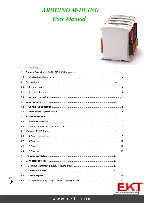
g e11. Index2. General Description M-DUINO FAMILY products ....................................................... 3 2.1. Mechanical dimensions ..................................................................................................... 43. Precautions .................................................................................................................. 4 3.1. Arduino Board ................................................................................................................... 4 3.2. Intended Audience ............................................................................................................ 4 3.3. General Precautions .......................................................................................................... 44. Specifications .............................................................................................................. 5 4.1. General Specifications: ...................................................................................................... 5 4.2. Performance Specification: ............................................................................................... 65. Before to connect: ....................................................................................................... 7 5.1. Software interface ............................................................................................................. 7 5.2. How to connect PLC arduino to PC ................................................................................... 76. M-duino 21 I/O Pinout: ............................................................................................... 9 6.1. A Zone connection ............................................................................................................ 9 6.2. A Zone top ....................................................................................................................... 10 6.3. B Zone .............................................................................................................................. 10 6.4. B Zone top ....................................................................................................................... 117. I/O technical details: ................................................................................................. 118. Connector details: ..................................................................................................... 129. I/O Pinout (summary pinout/ Arduino PIN): ............................................................. 13 10.Connection type .................................................................................................... 14 9.1. Digital Inputs ................................................................................................................... 14 ARDUINO M-DUINOUser Manualg e2Analog configuration mode: ................................................................................................ 15 Digital configuration mode: ................................................................................................ 16 9.3. Digital Outputs ................................................................................................................ 17 9.4.Analog (0-10Vdc) / PWM / Digital Outputs “configurable” ............................................ 18 Analog configuration mode: ................................................................................................ 18 Digital configuration mode: ................................................................................................ 19 PWM configuration mode: .................................................................................................. 20 9.5. Relay Outputs (Not available yet in M-duino family products) ...................................... 21 11. Communication Pinout.......................................................................................... 22 a.I2C Communication connection: (23)b. RS485 Communication connection: .......................................................................... 24 12. Mechanical Characteristics ................................................................................... 25 13. Software Interface: (26)g e32.General Description M-DUINOFAMILY productsA compact PLC based in Open Source Hardware technology. With different Input/Outputs Units.g e42.1. Mechanical dimensionsM-Duino 21 I/OsM-Duino 42 I/OsM-Duino 58 I/Os3. Precautions3.1. Arduino BoardAll M-duino family products use Arduino MEGA Board.3.2. Intended AudienceThis manual is intended for the following personal, which must also have knowledge of electrical systems.3.3. General PrecautionsThe user must operate the product according to the performance specifications described in the operation manuals.Before using the product under conditions, which are not described in the manual or applyingg e5combustion systems, medical equipment, amusement machines, safety equipment and other systems, machines, and equipment that may have a serious influence on lives and property if used improperly, consult your INDUSTRIAL SHIELDS representative.Make sure that the rating and performance characteristics of the product are sufficient for the systems, machines, and equipment, and be sure to provide the systems, machines, and equipment with double safety mechanisms.This manual provides information for programming and operating the Unit. Be sure to read this manual before attempting to use the Unit keep this manual close at hand for reference during operaion.Warnings:∙ Unused pins should not be connected. Ignoring the directive may damage thecontroller.∙ Improper use of this product may severely damage the controller. ∙ Refer to the cont roller’s User Guide regarding wiring considerations.∙ Before using this product, it is the responsibility of the user to read the product’s UserGuide and all accompanying documentation.4. Specifications4.1. General Specifications:g e6g e75. Before to connect:5.1. Software interfaceArduino IDE is compatible for programming these PLCs. You must to download a start code in at product page in “document files” section and then It is necessary open it with Arduino IDE. Configuration about Arduino IDE:5.2. How to connect PLC arduino to PC-Connect USB port from PLC to PC.NOTE:M-Duino Family use USB-B cable.-Open Arduino IDE interface: You can install with this link:/download.php?f=/arduino-1.0.6-windows.exe-Select Arduino BoardNOTE:M-Duino Family use Arduino MEGA 2560.IMPORTANT: For M-duino Family you need to take out the BlueJumper for programming.-Select correct port.g e8IMPORTANT:Verify the USB port is detected:g e96. M-duino 21 I/O Pinout:6.1. A Zone connection*NOTE: Don’t connect the jumper. Jumper is necessary only for serial communication. (Arduino mega has auto reset using serial communication code).Configuration SwitchUn/Protected*I/Os PinoutPower supply connectors (24Vdc – Gnd)Pin out functionA Z O N EB Z O N E B Z O N E A Z O N EB ZONE A ZONEg e106.2. A Zone top6.3. B ZoneNOTE: Select correctly configuration for use Inputs to correct function.1COM-I0.6 COM-I0.5 COM-I0.4 COM-I0.3 COM-I0.2 COM-I0.1 COM-I0.0 Configuration Switch*Input PinoutConfiguration Switch*Output PinoutPower led indicator Arduino Reset buttonUSB programmer connector (Arduino Mega)Ethernet connectorg e116.4. B Zone top7. I/O technical details:2You can select 24Vdc or 10Vdc (with correctly switch configuration). Digital output will be 12Vdc If you connect PLC to 12Vdc power supplyLed indicator I/Os stateg e128. Connector details:For I/O and power supply you have a FFKDS/H-2,54 connector from Phoenix contact Connection details:g e139. I/O Pinout (summary pinout/ Arduino PIN):g e1410. Connection type9.1. Digital Inputs- Programation Code (example):int I01 = 12; // Digital (24Vdc) void setup() {pinMode(I01, INPUT); }Void loop(){/* Lo que se quiera */ = digitalRead(I01); }NOTE:Some digital Inputs have an isolated signal. In this case is necessary to connect correctly ground (GND) in correctly “com” pin.g e159.2. Analog (0-10Vdc) / Digital Inputs “configurable”Analog configuration mode:-Programation Code (example):int I01 = A05; // select the Analog (0-10Vdc) / Digital (24Vdc)IN //**warning"" (if Analog selection connect 10Vdc MAX). int I02 = A04; // select the Analog (0-10Vdc) / Digital (24Vdc)IN //**warning"" (if Analog selection connect 10Vdc MAX). void setup() { pinMode(I01, INPUT); }Void loop(){ value = analogRead(A5);/* Lo que se quiera */ = digitalRead(I01); }Switch configuration (Select Analog position)g e16Digital configuration mode:-Programation Code (example):int I01 = A05; // select the Analog (0-10Vdc) / Digital (24Vdc)IN //**warning"" (if Analog slection connect 10Vdc MAX). int I02 = A04; // select the Analog (0-10Vdc) / Digital (24Vdc)IN //**warning"" (if Analog slection connect 10Vdc MAX). void setup() {pinMode(I01, INPUT); }Void loop(){ value = analogRead(A5);/* Lo que se quiera */ = digitalRead(I01);}Switch configuration (Select digital position)g e179.3. Digital Outputs- Programation Code (example):int Q06 = 3; // Relay output (220Vac, 5A) void setup() {pinMode(Q06, OUTPUT); }Void loop(){digitalWrite(Q06, HIGH); // Relay ON// turn the LED on (HIGH is the voltage level) delay(1000); // wait for a second digitalWrite(Q06, LOW); // Relay OFF// turn the LED off (LOW is the voltage level) }g e189.4. Analog (0-10Vdc) / PWM / Digital Outputs “configurable”Analog configuration mode:- Programation Code (example):int Q06 = 3;// select the Analog (0-10Vdc) / PWM (10 OR 24Vdc) /Digital //(24Vdc)OUTPUT int Q05 = 5;// select the Analog (0-10Vdc) / PWM (10 OR 24Vdc) /Digital //(24Vdc)OUTPUT void setup() {pinMode(Q06, OUTPUT); pinMode(Q05, OUTPUT); }Void loop(){analogWrite(Q06, /*valor de una variable */); digitalWrite(Q05, 125); Switch configurationSelect 10Vdc position switch Select Analog position switchg e19- Programation Code (example):int Q06 = 3;// select the Analog (0-10Vdc) / PWM (10 OR 24Vdc) /Digital //(24Vdc)OUTPUT int Q05 = 5;// select the Analog (0-10Vdc) / PWM (10 OR 24Vdc) /Digital //(24Vdc)OUTPUT void setup() {pinMode(Q06, OUTPUT); pinMode(Q05, OUTPUT); }Void loop(){analogWrite(Q06, 254);digitalWrite(Q05, HIGH); // Relay ON// turn the LED on (HIGH is the voltage level) delay(1000); // wait for a second analogWrite(Q06, 0);digitalWrite(Q06, LOW); // Relay OFF// turn the LED off (LOW is the voltage level) }Switch configurationSelect 24Vdc position switch Select Digital position switchConnection Digital Output (24Vdc)g e20- Programation Code (example):int Q06 = 3;// select the Analog (0-10Vdc) / PWM (10 OR 24Vdc) /Digital //(24Vdc)OUTPUT int Q05 = 5;// select the Analog (0-10Vdc) / PWM (10 OR 24Vdc) /Digital //(24Vdc)OUTPUT void setup() {pinMode(Q06, OUTPUT); pinMode(Q05, OUTPUT); }Void loop(){analogWrite(Q06, /*valor de una variable */); digitalWrite(Q05, 125); }Switch configurationSelect 24Vdc position switch Select Digital position switchConnection PWM Output (24Vdc)g e219.5. Relay Outputs (Not available yet in M-duino family products)- Programation Code (example):int Q06 = 3; // Relay output (220Vac, 5A) void setup() {pinMode(Q06, OUTPUT); }Void loop(){digitalWrite(Q06, HIGH); // Relay ON delay(1000); // wait for a second digitalWrite(Q06, LOW); // Relay OFF }g e2211.Communication PinoutIn A Zone you can select different types of Arduino communication PINS:You have different options and accessories. M-duino family products have directly Ethernet port with RJ45 connector.If you need to connect RS232 / RS485 / I2C M-duino family products have directly connection to Arduino Mega Board but it is necessary to connect with different accessories to use these kinds of communications protocols.3For correctly work. Select only one of this switch in ON Position. Example: Input I2.6 has 2 options. It can work like Interrupt 2 or SCL pin (for I2C communication port). If you use SCL wiring SCL PIN you must to switch on “SCL” switch position and switch off “Int2” switch position. If you use Int2. It’s necessa ry to wiring I2.6 (D Zone) you must to switch ON “Int2” and switch off “SCL”g e23a. I2C Communication connection:g e24b. RS485 Communication connection:P a g e2512.Mechanical Characteristics-Dimension M-duino Family:-DIN rail mounting:13. Software Interface:Arduino IDE is compatible for program these PLCs. You must to download a start code in at product page in “document files”section and then It’s necessary open it with Arduino IDE. Configuration about Arduino IDE:All Ardbox PLCs use an Arduino Leonardo and you need to choose these opcion in Arduino IDE.Note: Example Code is found in software-Enter to:-Press the icon to start the download /products/productdetails?ProductId=DC3B31F8-64E7-409E-9A8D-126A0F15194AHow to download the Software:。
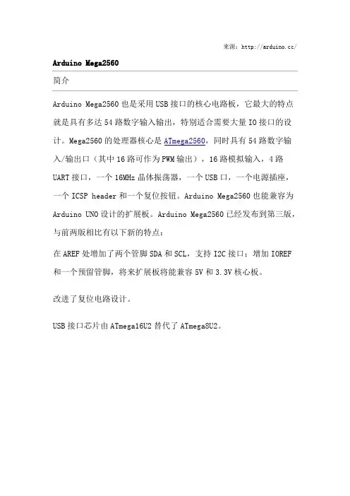
来源:Arduino Mega2560简介Arduino Mega2560也是采用USB接口的核心电路板,它最大的特点就是具有多达54路数字输入输出,特别适合需要大量IO接口的设计。
Mega2560的处理器核心是ATmega2560,同时具有54路数字输入/输出口(其中16路可作为PWM输出),16路模拟输入,4路UART接口,一个16MHz晶体振荡器,一个USB口,一个电源插座,一个ICSP header 和一个复位按钮。
Arduino Mega2560也能兼容为Arduino UNO设计的扩展板。
Arduino Mega2560已经发布到第三版,与前两版相比有以下新的特点:在AREF处增加了两个管脚SDA和SCL,支持I2C接口;增加IOREF和一个预留管脚,将来扩展板将能兼容5V和3.3V核心板。
改进了复位电路设计。
USB接口芯片由ATmega16U2替代了ATmega8U2。
概要▪处理器 ATmega2560▪工作电压 5V▪输入电压(推荐) 7-12V▪输入电压(范围) 6-20V▪数字IO脚 54 (其中16路作为PWM输出)▪模拟输入脚 16▪IO脚直流电流 40 mA▪ 3.3V脚直流电流 50 mA▪Flash Memory 256 KB (ATmega328,其中8 KB 用于bootloader)▪SRAM 8 KB▪EEPROM 4 KB▪工作时钟 16 MHz电路图和PCB▪电路图▪硬件设计文件(Eagle文件)▪引脚图电源Arduino Mega2560可以通过3种方式供电,而且能自动选择供电方式▪外部直流电源通过电源插座供电。
▪电池连接电源连接器的GND和VIN引脚。
▪USB接口直接供电。
电源引脚说明▪VIN --- 当外部直流电源接入电源插座时,可以通过VIN向外部供电;也可以通过此引脚向Mega2560直接供电;VIN有电时将忽略从USB或者其他引脚接入的电源。
Arduino认知这学期我们接触了一个新的课程——Arduino。
看着很难懂的一个名称,其实内容很有趣,过程很精彩,并且与上学期学的C语言有一定的相通之处,这给我们的学习过程减轻了很多难处。
这个学科我们一共做了11个实验,分别是光敏电阻、PWN脉宽调制、火焰传感器、4*4数码矩阵、温度传感器、4位数码管显示、人体传感器、RGB三色基LED、舵机控制、LCD1602、超声波测距。
每一个实验都都有不同的实验结果,会给我们带来不一样的体验,给我们增加了很多新奇的体验。
比如说,光敏电阻会因为光感的强弱来改变电阻的闪动频率;温度传感器可以检测到温度,改变呈现给我们数值;4位数码管显示器也很有意思,在程序上输入你想在数码管上显示的字母、数字,待程序完成并执行后就可以在数码管的液晶屏上看到你想呈现的东西;舵机控制的实验,可以看到舵机的螺旋桨转动;RGB三色基LED会出现红绿蓝三色接替闪烁,等等。
每完成一个实验,看到相应的实验结果就满满的成就感。
这里面的实验每一个都需要对应的程序来实现,所以我们每做一个实验的第一步就是敲程序,程序或多或少会有些枯燥,但一想到可以看不同的实验现象就会活力满满。
接下来就具体介绍以下Arduino的来源、作用及实用工具等。
Arduino是源于意大利的一套开源硬件开发平台,他的的作用是能通过各种各样的传感器来感知环境,通过控制灯光、马达和其他的装置来反馈、影响环境。
板子上的微控制器可以通过Arduino的编程语言来编写程序,编译成二进制文件,烧录进微控制器。
特色:可开放源代码的电路图设计,程序开发接口免费下载,也可依个人需求自己修改。
是使用低价格的微处理控制器(AVR系列控制器),可以采用USB接口供电,不需外接电源,也可以使用外部9VDC输入。
Arduino支持ISP在线烧,可以将新的“bootloader”固件烧入AVR芯片。
有了bootloader之后,可以通过串口或者USB to RS232线更新固件。
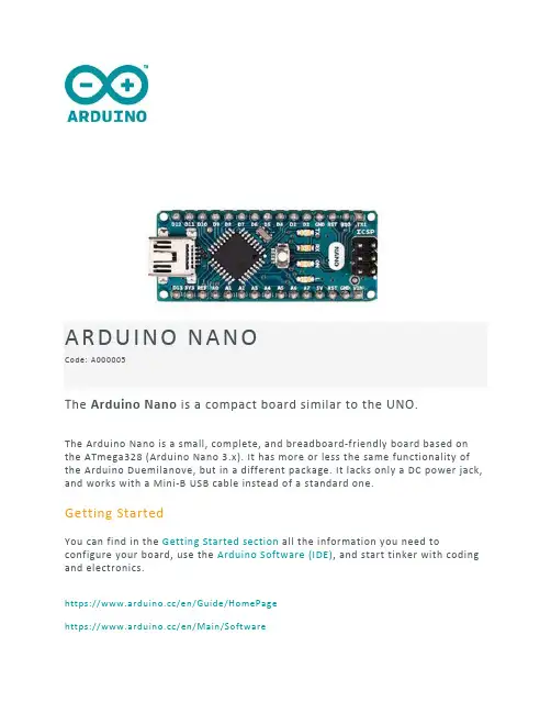
ARDUINO NANOCode: A000005The Arduino Nano is a compact board similar to the UNO.The Arduino Nano is a small, complete, and breadboard‐friendly board based on the ATmega328 (Arduino Nano 3.x). It has more or less the same functionality of the Arduino Duemilanove, but in a different package. It lacks only a DC power jack, and works with a Mini‐B USB cable instead of a standard one.Getting StartedYou can find in the Getting Started section all the information you need to configure your board, use the Arduino Software (IDE), and start tinker with coding and electronics.https:///en/Guide/HomePagehttps:///en/Main/SoftwareTECH SPECSMicrocontroller ATmega328Architecture AVROperating Voltage 5 VFlash Memory 32 KB of which 2 KB used by bootloaderSRAM 2 KBClock Speed 16 MHzAnalog I/O Pins 8EEPROM 1 KBDC Current per I/O Pins 40 mA (I/O Pins)Input Voltage 7‐12 VDigital I/O Pins 22PWM Output 6Power Consumption 19 mAPCB Size 18 x 45 mmWeight 7 gProduct Code A000005OSH: SchematicsThe Arduino Nano is open‐source hardware! You can build your own board using the following files:EAGLE FILES IN .ZIPhttps:///assets/arduino‐nano‐reference.zipSCHEMATICS IN .PDFhttps:///en/uploads/Main/Arduino_Nano‐Rev3.2‐SCH.pdfPowerThe Arduino Nano can be powered via the Mini‐B USB connection, 6‐20Vunregulated external power supply (pin 30), or 5V regulated external power supply (pin 27). The power source is automatically selected to the highest voltage source.MemoryThe ATmega328 has 32 KB, (also with 2 KB used for the bootloader. TheATmega328 has 2 KB of SRAM and 1 KB of EEPROM.Input and OutputEach of the 14 digital pins on the Nano can be used as an input or output, using pinMode(), digitalWrite(), and digitalRead() functions. They operate at 5 volts.Each pin can provide or receive a maximum of 40 mA and has an internal pull‐up resistor (disconnected by default) of 20‐50 kOhms. In addition, some pins have specialized functions:∙Serial: 0 (RX) and 1 (TX). Used to receive (RX) and transmit (TX) TTL serial data. These pins are connected to the corresponding pins of the FTDI USB‐to‐TTL Serial chip.∙External Interrupts: 2 and 3. These pins can be configured to trigger an interrupt on a low value, a rising or falling edge, or a change in value. See the attachInterrupt() function for details.∙PWM: 3, 5, 6, 9, 10, and 11. Provide 8‐bit PWM output with the analogWrite() function.∙SPI: 10 (SS), 11 (MOSI), 12 (MISO), 13 (SCK). These pins support SPI communication, which, although provided by the underlying hardware, is not currently included in the Arduino language.∙LED: 13. There is a built‐in LED connected to digital pin 13. When the pin is HIGH value, the LED is on, when the pin is LOW, it's off.The Nano has 8 analog inputs, each of which provide 10 bits of resolution (i.e.1024 different values). By default they measure from ground to 5 volts, though is it possible to change the upper end of their range using the analogReference()function. Analog pins 6 and 7 cannot be used as digital pins. Additionally, some pins have specialized functionality:∙I2C: 4 (SDA) and 5 (SCL). Support I2C (TWI) communication using the Wire library (documentation on the Wiring website).There are a couple of other pins on the board:∙AREF. Reference voltage for the analog inputs. Used with analogReference().∙Reset. Bring this line LOW to reset the microcontroller. Typically used to add a reset button to shields which block the one on the board.CommunicationThe Arduino Nano has a number of facilities for communicating with a computer, another Arduino, or other microcontrollers. The ATmega328 provide UART TTL (5V) serial communication, which is available on digital pins 0 (RX) and 1 (TX). An FTDI FT232RL on the board channels this serial communication over USB and the FTDI drivers (included with the Arduino software) provide a virtual com port to software on the computer. The Arduino software includes a serial monitor which allows simple textual data to be sent to and from the Arduino board. The RX and TX LEDs on the board will flash when data is being transmitted via the FTDI chip and USB connection to the computer (but not for serial communication on pins 0 and 1). A SoftwareSerial library allows for serial communication on any of the Nano's digital pins. The ATmega328 also support I2C (TWI) and SPI communication. The Arduino software includes a Wire library to simplify use of the I2C bus. To use the SPI communication, please see ATmega328 datasheet.ProgrammingThe Arduino Nano can be programmed with the Arduino software (download). Select "Arduino Duemilanove or Nano w/ ATmega328" from the Tools > Board menu (according to the microcontroller on your board). The ATmega328 on the Arduino Nano comes preburned with a bootloader that allows you to upload new code to it without the use of an external hardware programmer. It communicates using the original STK500 protocol. You can also bypass the bootloader and program the microcontroller through the ICSP (In‐Circuit Serial Programming) header using Arduino ISP or similar.Automatic (Software) ResetRather then requiring a physical press of the reset button before an upload, the Arduino Nano is designed in a way that allows it to be reset by software running on a connected computer. One of the hardware flow control lines (DTR) of theFT232RL is connected to the reset line of the ATmega328 via a 100 nanofarad capacitor. When this line is asserted (taken low), the reset line drops long enough to reset the chip. The Arduino software uses this capability to allow you to upload code by simply pressing the upload button in the Arduino environment. This means that the bootloader can have a shorter timeout, as the lowering of DTR can bewell‐coordinated with the start of the upload. This setup has other implications. When the Nano is connected to either a computer running Mac OS X or Linux, it resets each time a connection is made to it from software (via USB). For the following half‐second or so, the bootloader is running on the Nano. While it is programmed to ignore malformed data (i.e. anything besides an upload of new code), it will intercept the first few bytes of data sent to the board after aconnection is opened. If a sketch running on the board receives one‐time configuration or other data when it first starts, make sure that the software with which it communicates waits a second after opening the connection and before sending this data.https:///usa/arduino‐usb‐2‐serial‐micro 12‐7‐17。
Arduino和单片机区别,及Arduino入门教程展开全文素材来源:DF创客社区编辑整理:strongerHuang搞单片机的读者都应该听说过Arduino,或者用过Arduino,但很多小伙伴还是不清楚究竟什么是Arduino,今天就针对初学者简单描述一下 Arduino 相关内容。
一、初识Arduino要了解Arduino就先要了解什么是单片机,Arduino平台的基础其实就是AVR指令集的单片机。
1、什么是单片机?一台能够工作的计算机包含以下几个部份:中央处理单元CPU (进行运算、控制)、随机存储器RAM(数据存储)、存储器ROM (程序存储)、输入/输出设备I/O(串行口、并行输出口等)。
在个人计算机(PC)上这些部份被分成若干块芯片,安装在一个被称之为主板的印刷线路板上。
而在单片机中,这些部份全部被做到一块集成电路芯片中了,所以就称为单片(单芯片)机,而且有一些单片机中除了上述部份外,还集成了其它部份如模拟量/数字量转换(A/D)和数字量/模拟量转换(D/A)等。
2、单片机有什么用?所谓杀鸡焉用牛刀,并不是任何场合都需要很高的性能。
想象一个使用Intel i7处理器的声控灯,其性价比一定低到突破天际了。
应用的关键是看是否够用,是否有很好的性能价格比,于是单片机很好地填补了这个缝隙。
回过头来,那什么是Arduino?Arduino 是一款便捷灵活、方便上手的开源电子原型平台,包含硬件(各种型号的Arduino板)和软件(Arduino IDE)。
它适用于艺术家、设计师、爱好者和任何“想捣腾”的朋友们。
特点就是形状简单,能够实现与人互动,十岁的孩子也能用它做出一些自己想要的东西。
Arduino能通过各种各样的传感器来感知环境,通过控制灯光、马达和其他的装置来反馈、影响环境。
板子上的微控制器可以通过Arduino的编程语言来编写程序,编译成二进制文件,收录进微控制器。
基于Arduino的项目,可以只包含Arduino,还可以包含Arduino和其他一些在PC上运行的软件,他们之间进行通信(比如Flash, Processing, MaxMSP)来实现。
来源:/ Arduino Mega2560简介Arduino Mega2560也是采用USB接口的核心电路板,它最大的特点就是具有多达54路数字输入输出,特别适合需要大量IO接口的设计。
Mega2560的处理器核心是ATmega2560,同时具有54路数字输入/输出口(其中16路可作为PWM输出),16路模拟输入,4路UART接口,一个16MHz晶体振荡器,一个USB口,一个电源插座,一个ICSP header 和一个复位按钮。
Arduino Mega2560也能兼容为Arduino UNO设计的扩展板。
Arduino Mega2560已经发布到第三版,与前两版相比有以下新的特点:在AREF处增加了两个管脚SDA和SCL,支持I2C接口;增加IOREF和一个预留管脚,将来扩展板将能兼容5V和3.3V核心板。
改进了复位电路设计。
USB接口芯片由ATmega16U2替代了ATmega8U2。
概要▪处理器 ATmega2560▪工作电压 5V▪输入电压(推荐) 7-12V▪输入电压(范围) 6-20V▪数字IO脚 54 (其中16路作为PWM输出)▪模拟输入脚 16▪IO脚直流电流 40 mA▪ 3.3V脚直流电流 50 mA▪Flash Memory 256 KB (ATmega328,其中8 KB 用于bootloader)▪SRAM 8 KB▪EEPROM 4 KB▪工作时钟 16 MHz电路图和PCB▪电路图/en/uploads/Main/arduino-mega2560 -schematic.pdf▪硬件设计文件(Eagle文件)/en/uploads/Main/arduino-mega25 60-reference-design.zip▪引脚图/en/Hacking/PinMapping2560电源Arduino Mega2560可以通过3种方式供电,而且能自动选择供电方式▪外部直流电源通过电源插座供电。
基于Arduino的简易亮光报警器的设计与实现作者:刘敏刘泽军宋庆国来源:《电子世界》2012年第21期【摘要】本文叙述了什么是Arduino及其特色;对ATmega单片机进行了简单介绍;详细的叙述了光敏电阻的结构和工作原理。
阐述了亮光报警器的基本原理和组成,给出了器件清单、连线方法、源程序及程序下载方法。
最后指出Arduino应用前景。
【关键词】Arduino;光敏电阻;单片机1.引言在2011年举行的Google I/O开发者大会上,Google发布了基于Arduino的Android Open Accessory标准和ADK工具,大家对Arduino的前景十分看好。
Phillip Torrone大胆地预测Google将用Android+Arduino的形式掀起自己的“Kinect模式”浪潮。
目前,国内关注Arduino 的人越来越多。
笔者爱好电子制作,接触Arduino较早,希望通过自己的努力让更多的人了解Arduino。
Arduino具有丰富的接口,简便的编程环境,极大的自由度,可拓展性能非常高,没有复杂的单片机底层代码,没有难懂的汇编,只是简单而实用的函数,它必将引领一个新的时代!2.Arduino2.1 什么是ArduinoArduino是什么?Arduino是源自意大利的一个开放源代码的硬件项目,Arduino是一块基于开放源代码的USB接口Simple I/O接口板(包括12通道数字GPIO,4通道PWM输出,6-8通道10bit ADC输入通道),并且具有使用类似Java,C语言的IDE集成开发环境。
Arduino 是一种开放资源的硬件设计,任何人都可以自由的设计,制作自己的Arduino兼容板,便于与计算机和许多其它连接器相连,通过连接器又可以连接到外部电子装置和器件,Arduino可以使用开发完整的电子元件例如Switch或Sensors或其他控制器、LED、步进马达或其他输出装置。
Arduino UNO 样板调试Arduino UNO已经推出一段时间了,虽然我们很早就基于官网公布的参考实现把电路板做出来了,但一直基于苦于相应的芯片非常难订购到,所以直到前两天才装好第一块样板,先上个成品图(注意,没有Arduino的商标以及MADE IN CHINA):从硬件上看,Arduino UNO与之前Arduino 2009版本的最大不同在于USB转串口部分,Arduino 2009采用的是FTDI专用芯片FT232RL,而Arduino UNO采用的是用一块ATmega8模拟出串口的做法。
这一改动着实给我们带来了不小的麻烦,第一是该方案所采用的ATmega8U2芯片基本上在市场上很难找到,另外一点就是该芯片的封装加大了焊接的难度的成本。
在研究原理图的过程中,发现其在USB引脚上加入了防止静电的元件,感觉应该会更加稳定。
拿到焊好的样板之后,首先要向ATMega8U2内写入相应的USB固件(firmware)。
在最新版本的Arduino-0021安装目录下的hardware\arduino\firmwares目录下,我们可以找到为Arduino UNO 编译好的USB固件文件UNO-dfu_and_usbserial_combined.hex。
Arduino UNO上为ATMega8U2单片机也留出了ICSP接口,我们可以借助它来下载相应的USB固件,使用的工具仍然是USBTinyISP,其右上角为ICSP的1脚:下载时使用的命令为:avrdude -p at90usb82 -F -P usb -c usbtiny -Uflash:w:UNO-dfu_and_usbserial_combined.hex-U lfuse:w:0xFF:m -U hfuse:w:0xD9:m -U efuse:w:0xF4:m -U lock:w:0x0F:m有意思的是写入USB固件时标明的芯片类型为AT90USB82,这显然与板子上使用的ATMega8U2不同,下载过程中avrdude也提示了这一点,估计两者的功能是比较类似的,或者就是同一芯片的不同版本罢了。
Arduino IDE Nano 使用说明书V.1.0版本修订历史目录第一章绪论 (4)1.1编写目的 (4)1.2产品简介 (4)1.3关于Arduino Nano (4)第二章准备篇 (6)2.1开发环境Arduino IDE (6)2.1.1 安装IDE (6)2.1.2 安装驱动 (8)2.1.3 IDE界面介绍 (12)第三章程序编写 (15)3.1 Hello Arduino ! (15)3.1.1 运行程序与观察实验结果 (15)第一章绪论1.1 编写目的为广大电子爱好者创客提供快捷、实用、方便的开发学习平台。
让广大电子爱好者更好的掌握Arduino及其扩展系统设计的方法和设计原则,以及相应的硬件调试方法。
进一步加深对Arduino及其扩展系统设计和应用的理解。
本教程将由浅入深,带领大家一起学习Arduino的各个功能,为您开启全新的Arduino之旅。
本手册共分为两部分:1.准备篇:主要介绍Arduino常用开发软件的使用以及一些下载调试的技巧。
2.实战篇:主要包括软件和硬件,硬件部分主要介绍各模块功能、原理;软件部分主要介绍各部分程序。
1.2 产品简介Arduino-RFID-Kit 是基于Arduino NANO 作为核心主控,L298N作为电机驱动的一款多功能学习套件,Arduino套件配套了各种传感器模块,可灵活连接。
Arduino配套各类资料,技术手册,例程等,手把手教你从入门到精通。
每位电子爱好者都可轻松上手,实现自己想要的功能。
1.3关于Arduino NanoArduino-Nano-Kit以Arduino Nano作为主控板,有14个数字输入/输出引脚(其中6个可用作PWM输出)、6个模拟输入、1个16 MHz陶瓷谐振器、1个USB连接、1个电源插座、1个ICSP 头和1个复位按钮。
它包含了支持微控制器所需的一切,只需通过USB电缆将其连至计算机或者通过AC-DC适配器或电池为其供电即可开始。
ArduinoMega2560使用手册编辑整理:尊敬的读者朋友们:这里是精品文档编辑中心,本文档内容是由我和我的同事精心编辑整理后发布的,发布之前我们对文中内容进行仔细校对,但是难免会有疏漏的地方,但是任然希望(ArduinoMega2560使用手册)的内容能够给您的工作和学习带来便利。
同时也真诚的希望收到您的建议和反馈,这将是我们进步的源泉,前进的动力。
本文可编辑可修改,如果觉得对您有帮助请收藏以便随时查阅,最后祝您生活愉快业绩进步,以下为ArduinoMega2560使用手册的全部内容。
来源:/ Arduino Mega2560简介Arduino Mega2560也是采用USB接口的核心电路板,它最大的特点就是具有多达54路数字输入输出,特别适合需要大量IO接口的设计.Mega2560的处理器核心是ATmega2560,同时具有54路数字输入/输出口(其中16路可作为PWM输出),16路模拟输入,4路UART接口,一个16MHz晶体振荡器,一个USB口,一个电源插座,一个ICSP header和一个复位按钮。
Arduino Mega2560也能兼容为Arduino UNO设计的扩展板。
Arduino Mega2560已经发布到第三版,与前两版相比有以下新的特点:在AREF处增加了两个管脚SDA和SCL,支持I2C接口;增加IOREF和一个预留管脚,将来扩展板将能兼容5V和3.3V核心板.改进了复位电路设计。
USB接口芯片由ATmega16U2替代了ATmega8U2。
概要▪处理器 ATmega2560▪工作电压 5V▪输入电压(推荐) 7-12V▪输入电压(范围) 6—20V▪数字IO脚 54 (其中16路作为PWM输出)▪模拟输入脚 16▪IO脚直流电流 40 mA▪ 3.3V脚直流电流 50 mA▪Flash Memory 256 KB (ATmega328,其中8 KB 用于 bootloader)▪SRAM 8 KB▪EEPROM 4 KB▪工作时钟 16 MHz电路图和PCB▪电路图/en/uploads/Main/arduino—mega2560—schematic.pdf▪硬件设计文件(Eagle文件)http://arduino。
使用Arduino Diecimila(Uno)给Atmega328P烧写
BootLoader
我有一个旧的Arduino Diecimila的和一些新的Atmega328p -PU芯片。不应该有,但我
带来一些没有引导程序的来节省一些钱。
接下来是什么?搜索操作步骤,看看我是否能烧引导程序到这些芯片。不幸的是无法工
作。出现一个错误消息"avrdude: stk500_getsync(): not in sync: resp=0x00 avrdude:
stk500_disable(): protocol error, expect=0x14, resp=0x51"。
有一个办法是焊接Arduino Diecimila上的一些引脚来解决这个问题,但是,Arduino是
我唯一有的一个,所以我并不想改变我的工作板。
步骤1:打开sketch ArduinoISP和连接电线
所以,我打开ArduinoISP sketch 检查。然后发现大多数操作步骤已经错过了一个环节:连
接Arduino的pin 10到Atemega328P的pin 1(复位)。我连接那根线,然后一切正常。当
然那是多次尝试后才有的事。
连接如截图所示。第一列是指到Arduino Diecimila,第二列是指Atmega328p,
Pin 10 - >pin 1(在我这里,这是非常重要的,如果没有它,IDE会提示错误,然后烧录失
败)
Pins 13, 12, 11 -> pins 19, 18, 17
Pins 10 -> pin 1
Vcc -> pins 7, 20
Gnd -> pins 8, 22
然后 连接晶振和电容到Atmega328p
晶振16Mhz -> pins 9, 10
电容22pf -> pins 8,9
电容22pf -> pins 8, 10
现在硬件部分搞定。然后把Arudino Diecimila插入到您的计算机,并按照下一个步骤走。
步骤2:下载ArduionISP程序和开始烧写bootloader
我知道我的Arduino是内嵌Atmega168p的 Diecimila,我将要烧录Arduino UNO到我的
Atmega328p,现在开始。
首先上传程序把我的Diecimila设置为ArduioISP
1、 选择 Tools -> Board -> Arduion Diecimila,Duemilanove,或Nano w/ ATmega168
注:如果你使用Arduino Uno,方法相同,选择 Tools -> Board -> Arduion Uno
2、编译然后上传ArduinoISP sketch。您应该看到“完成上传”
3、现在选择Tools - > Board - > Arduino UNO
4、选择Tools - > Burn Bootloader - > w/ Arduino as ISP,在一分钟内,你应该看到“完成
烧录bootloader”
如果你是幸运的,你很容易在一分钟内到达步骤4。要烧第二Atmega328p,拔下USB电
缆,交换一个新的328p到你的面包板再插上USB线,并再次运行步骤4。
如果发现任何错误,检查接线,然后再一次按照步骤一个一个操作一遍。
步骤3: 测试烧写完 bootloaded 的Atmega328p
要测试有bootloader后的Atmega328p能否工作,我只是用它换下我的Arduino Diecimila
上的Atmega168,然后按照正常sketch上传程序步骤,如下。
1、加载Blink程序。改变LED的开启和关闭时间,所以你知道atmega328p中运行的程序
是你独一无二的程序
2、从Arduino的IDE中,选择Tools -> Board -> Arduino UNO
3、把LED插入您的Arduino GND脚和pin 13之间
4、用Atmega328p换下 Atemega168。当你拔下芯片时要小心。越轻柔,损坏芯片的可能
越小。我用了两个针头,以帮助拔下芯片:)
5、把Arduino插回到您的计算机。确保你听到哔一声,电脑确认识别到你的板
6、编译并上传。那么你应该看到你在第1步中设置的LED闪烁的方式。
如果不工作,请检查第2步,并遵循上述步骤再试。
为了测试另一片Atmega328p,重复步骤4至6。
这就是一切。享受它。