电气专业毕业论文外文翻译
- 格式:doc
- 大小:160.00 KB
- 文档页数:16

英文原文:Power system communication power supply test and maintenance ofthe battery solutionAbstractIn a large number of data experiments and field application, and on the basis of the telecom room in the power the power of common common problems are analyzed and discussed, from, testing and maintenance of real-time monitoring system safety, and put forward a set of complete solutions.Keywords: battery group; Power source; Detection; maintenanceIntroductionThe electric power communication system center room equipped with a large amount of storage battery installation, on the communications department.The operation of the electric power systems and support, spare play an important role. But in the maintenance process, or will often meet many problems, a detailed analysis of the below.1. The battery power supply condition and analyzes the reasonsWe for large communication machine. Room on the actual test, to the battery power supply system for the comprehensive study, found that many rooms, communications equipment have low load capacity battery, system reliability of the poor, in here are two groups of data about battery problems:A. battery service life for the design of the general 8-1 O years, and statistical data show that the battery life ideal circumstances can achieve 4-6 years, generally can not meet the design demand, a large number of telecommunication room used less than 3 years (some two years) appear behind battery, part of the battery even scrapped;B. 2010 years urumqi power bureau telecommunication room data show that because the battery electric power communication power supply fault from accidents accounted for 35%, in recent years the data interface rapidly, the ratio has risen to 7%.Two sets of data to show that the problem is more serious battery, the battery power supply of security and reliability have a serious threat, investigate its reason, mainly in the following nine aspects:1.1 battery design process qualityThe battery design process exists plate technology design, material design, oxygen composite design, the pressure setA comprehensive plan defect, make a battery performance and life have been affected, main performance for battery failure, early leakage water loss, deformation cracks, etc.For simple ascending battery capacity, will the battery plate thin, and increase the number plate, makes the same volume of the casing electrolyte reaction area greatly increased, capacity improve soon, but because thin plate, plate easily corrosion, softening battery, service life and therefore greatly shorten, easy to produce the early failure problems.Because of the low pressure setting, charge once to a certain pressure, control valves will be openRev., gas is through the valve were leaked, cause the battery fluid loss (usually in a hole or a column valve will find a slightly damp near the liquid), this kind of battery also easy to produce the early failure, valve pressure design and material also has a direct relationship between the shell.Due to shell material, oxygen composite efficiency, valve design pressure, and other comprehensive technology lack, some batteries in the process of charging and discharging pool, easy to produce the shell deformation, beat even crack.1.2 the influence of the operation environmentRunning environment is the main room temperature on battery life influence is bigger, in 25 ℃environment conditions, the environmental average temperature increase every 10 ℃, battery life is reduced by half. Northwest temperature changes greatly (a 30 ℃a + 55 ~ C), the substation telecommunication room less equipped with air conditioner, thermal performance is poor, temperature on battery life form directly influence.1.3 operation mode and installation methodBattery packs are generally more battery series into a group, two groups of parallel operation. Site oftenFound in the internal battery, article connection (board) corner of battery performance generally have slightly worse, the main reason is the article connection too long (other connection is the article 5 a l0 times) and the materials of the contact resistance caused too large, lead to the connection of pressure drop article is too big, in the process of charging and discharging, will seriously affect peripheral battery charging and discharging effect, this kind of problem should be avoided.1.4 the quality of power supply and load design problemThe telecom room is located in remote general transformer substation, often without power and the battery in frequent charged, and discharge status, the serious influence battery life. Computer room load relative to the battery capacity are slants small, such as the actual load for 30 A, communications equipment configuration of battery capacity is commonly two groups of 300 Ah, the utility after interrupting, storage battery will to tiny current began to discharge, and small discharge current generation of sulfuric acid lead particles is easy to crystallization into pieces and E telecommunication room are generally rural power supply, the quality of power supply is not stable, power over A long period of time, power outages frequent, sulfuric acid lead particles generated more easily irreversible sulfate.1.5 professional testing methods and lack of equipmentIn the discharge detection, due to lack of monomer detection equipment protection functions, therefore, in discharge only by the group when voltageobservation, combined with manual measuring for inspection. Find a 1.8 v battery, immediately suspend test. This way low efficiency, safety all the sex differences, to the battery can't form an effective protection.The battery characteristic parameters are mainly embodied in the voltage, resistance and capacity, the conventional detection method mainly measuring voltage, observe the shell signs, check the bolt tightness etc. So that only some representations to the parameter, and cannot master's important! Parameters such as resistance, capacity, etc.1.6 charger, discharge management system is not perfectRecharging problems mainly involves to charge cycle, all are charging pressure, flow, all are charging filling time,All filling conversion control, float temperature compensation of detailed regulations.Some maintenance personnel to improve battery charging efficiency, improved charging voltage, and increase the charging current, leading to increased pressure, then combined low efficiency, the battery to dehydrate, are plate bar corrosion. With this several years of battery management know deeply, related problems reduce gradually, but for this problem or must cause enough attention to main pay attention to the following three points: one is the charge can't charge high pressure, even with are charging, voltage must also be restricted in 2.35 V scope (the new battery should be controlled in 2-3 V); 2 it is charging electric current cannot too much, it will speed up plates corrosion, cause plate softening, restrain oxygen composite efficiency; 3 it is charging process must be temperature compensation, compensation coefficients for a 3 mV / ℃2 mV / ~ C one.2. Testing and maintenance program2.1 replacement has serious degradation the battery packs, strengthen the selection of the batteryTo find Bi can have depth degradation and a serious threat to the security of the battery power supply systemGroups should be early change, and strengthen the battery technology selection. Process quality problem is the focus of the selection consider battery, the battery can be based on standard, battery makers to raise specific technical requirements, such as of the materials, valve pressure., plate thickness, quantity, voltage, resistance Sui, balanced equilibrium characteristics, oxygen composite efficiency, water loss rate, for through the acceptance test can detect project, must conduct test on these work can be further ensure the reliability of the battery for long-term use.Vrla batteries for production technology is strict, at present domestic battery lifeManufacturers in the more than 300, all sorts of technology of handicraft is various, the proposal is in before purchase, the battery rigorous screening, as far as possible choice complete production equipment, strong technical force, service facilities, perfect brand enterprise. ,2.2 strengthen early battery test, improve battery support ability of put into operationAt the beginning of the storage battery check is a very important testing link, the battery technology standardsIn early to check the battery has a clear request, the engine room of the electric power communication battery installation, run and maintenance and management is of important significance. For the specific requirements of the early battery check is: batteries before put into operation, the first first check sex discharge, its capacity should be not less than 95%, after the completion of the discharge to the battery charge; Filled, a quiet place 1-2 h, make a second check sex discharge, after the completion of the discharge of battery charge; Filled, a quiet place 1 ~ 2 h, third check Bi discharge, its capacity should be not less than 100%, after the completion of the discharge to charge the battery.2.3 maintenance change ideas, strengthen the battery power supply of professional monitoring managementProfessional centralized monitoring system in the traditional monitoring system based on the function, increase the storage of electricityPool monomer battery voltage, resistance and check test functions, the more the earth played a monitoring management functions, improve the maintenance efficiency.Implementing specialized monitoring, and other installation common monitoring or not pack monitoring communications equipment phaseThan, the power supply rate reduced greatly, found that the problem is timely, ensure the safety and reliability of the telecom room improved.2.4 configuration diesel generators, strengthen intelligent control management, ensure that electric power communication securityThe battery electric power communication communications equipment is necessary short time dc power, and diesel generatorMachine is long time plays the role of communication standby power. Most of the communications are no spare room woodOil generator, can increase the small diesel generator configuration.Considering the maintenance workload is big, shortage of personnel, vehicles and equipment and turnover nervous the actual problem, can not intelligent diesel generator increase intelligent control system, in the utility power lost, the utility is unstable, the phase lack, owe pressure, pressure and so on many kinds of conditions, can be automatically start diesel generator, and to switch into power network operation.For the operation of the diesel generator maintenance and management, should also together with battery, into the professional centralized monitoring system, so that in time control system of power the battery operation parameters and working state.中文翻译:电力系统通信蓄电池电源的检测与维护解决方案摘要在大量的数据实验和现场应用的基础上,针对电力通信机房电源普遍存在的共同性问题进行了分析和探讨,从检测维护、实时监控及系统安全等角度提出了一套完整方案。
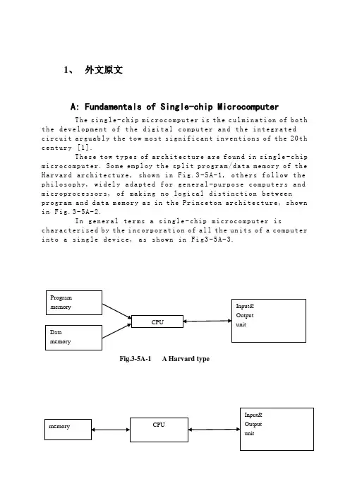
1、外文原文A: Fundamentals of Single-chip MicrocomputerTh e si ng le-c hi p m ic ro co mp ut er i s t he c ul mi na ti on of b oth t h e de ve lo pm en t o f t he d ig it al co m pu te r an d th e i n te gr at edc i rc ui t a rg ua bl y t h e to w m os t s ig ni f ic an t i nv en ti on s o f t he20th c e nt ur y [1].Th es e t ow ty pe s of ar ch it ec tu re a re fo un d i n s in g le-c hip m i cr oc om pu te r. So m e em pl oy t he spl i t pr og ra m/da ta m e mo ry o f th e H a rv ar d ar ch it ect u re, sh ow n in Fi g.3-5A-1, o th ers fo ll ow t he p h il os op hy, wi del y a da pt ed f or ge n er al-p ur po se co m pu te rs a nd m i cr op ro ce ss o r s, o f ma ki ng n o log i ca l di st in ct ion be tw ee np r og ra m an d d at a m e mo ry a s i n t he P r in ce to n ar ch ite c tu re, sh ow n i n F ig.3-5A-2.In g en er al te r ms a s in gl e-chi p m ic ro co mp ut er i sc h ar ac te ri zed b y t he i nc or po ra ti on of a ll t he un it s of a co mp ut er i n to a s in gl e d ev i ce, as s ho wn in Fi g3-5A-3.Fig.3-5A-1 A Harvard typeFig.3-5A-2. A conventional Princeton computerFig3-5A-3. Principal features of a microcomputerRead only memory (ROM).R OM i s us ua ll y f or th e p e rm an en t,n o n-vo la ti le s tor a ge o f an a pp lic a ti on s pr og ra m .M an ym i cr oc om pu te rs an d m ar e in te nd e d f or hi gh-v ol um e a p pl ic at io ns a n d he nc e t h e eco n om ic al m an uf act u re o f th e de vic e s re qu ir es t h at t he co nt en t s o f t he pr og ra m me m or y b e co mm it t ed pe rm a ne nt ly d u ri ng t he m an ufa c tu re o f ch ip s .Cl ea rl y, t hi s i m pl ie s ar i go ro us a pp ro ach to R OM c od e de ve l op me nt s in ce ch a ng es c an no t b e m ad e af te r m anu f a c tu re .Th is d ev e lo pm en t pr oc ess ma y in vo lv e e m ul at io n us in g a so ph is ti ca te d d e ve lo pm en t sy ste m w it h ah a rd wa re e mu la tio n c ap ab il it y as w el l as t he u se o f po we rf ul s o ft wa re t oo ls.So me m an uf act u re rs p ro vi de ad d it io na l RO M opt i on s byi n cl ud in g i n th eir r a n ge d ev ic es wi t h (or i nt en de d f o r u se w it h) u s er p ro gr am ma ble me mo ry. Th e sim p le st o f th es e i s u su al lyd e vi ce w hi ch c an o p er at e in a mi cro p ro ce ss or m od e b y u si ng s om e o f t he i np ut/o utp u t li ne s as a n a d dr es s an d da ta b us f ora c ce ss in g ex te rna l m em or y. T hi s t y pe o f de vi ce ca nb eh av ef u nc ti on al ly a s t h e si ng le ch ip mi cr oc om pu te r fro m w hi ch it is d e ri ve d al be it wi t h re st ri ct ed I/O a nd a m od if ied ex te rn alc i rc ui t. Th e u se o f th es ed ev ic es i s c om mo ne ve n i n pr od uc ti on c i rc ui ts wh er e t he vo lu me do es no t j us tif y t h e d ev el o pm en t c os ts o f c us to m o n-ch i p R OM[2];t he re c a n s ti ll be a s ig nif i ca nt sa vi ng i n I/O an d o th er c h ip s c om pa re d t o a co nv en ti on al mi c ro pr oc es so r b a se d ci rc ui t. Mo r e ex ac t re pl ace m en t fo r RO M dev i ce s ca n be o b ta in ed i n th e f o rm o f va ri an ts w it h 'p ig gy-b ack'E P RO M(Er as ab le pr o gr am ma bl e RO M )s oc ke ts o r d ev ic e s wi th EP RO M i n st ea d o f RO M 。
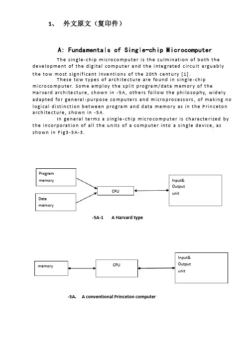
1、 外文原文(复印件)A: Fundamentals of Single-chip MicrocomputerT h e sin gle -ch ip mi c ro co m p u t e r is t h e cu lm in at io n of b ot h t h e d e ve lo p me nt of t h e d ig ita l co m p u t e r a n d t h e i nte g rated c ircu it a rgu ab l y t h e to w mo st s ign if i cant i nve nt i o n s of t h e 20t h c e nt u ry [1].T h ese to w t yp e s of arch ite ct u re are fo u n d in s in gle -ch ip m i cro co m p u te r. S o m e e mp l oy t h e sp l it p ro gra m /d at a m e m o r y of t h e H a r va rd arch ite ct u re , s h o wn in -5A , ot h e rs fo l lo w t h e p h i lo so p hy, wid e l y ad a p ted fo r ge n e ral -p u rp o se co m p u te rs an d m i cro p ro ce ss o rs , of m a kin g n o l o g i ca l d i st in ct i o n b et we e n p ro gra m an d d ata m e m o r y as in t h e P rin c eto n a rch ite ct u re , sh o wn in -5A.In ge n e ra l te r m s a s in g le -ch ip m ic ro co m p u t e r is ch a ra cte r ized b y t h e in co r p o rat io n of all t h e u n its of a co mp u te r into a s in gle d e vi ce , as s h o w n in F i g3-5A-3.-5A-1A Harvard type-5A. A conventional Princeton computerProgrammemory Datamemory CPU Input& Output unitmemoryCPU Input& Output unitResetInterruptsPowerFig3-5A-3. Principal features of a microcomputerRead only memory (ROM).RO M is u su a l l y fo r t h e p e r m an e nt , n o n -vo lat i le sto rage of an ap p l i cat io n s p ro g ram .M a ny m i c ro co m p u te rs a n d m i cro co nt ro l le rs are inte n d ed fo r h i gh -vo lu m e ap p l i cat io n s a n d h e n ce t h e e co n o m i cal man u fa c t u re of t h e d e vi ces re q u ires t h at t h e co nt e nts of t h e p ro gra m me mo r y b e co mm i ed p e r m a n e nt l y d u r in g t h e m a n u fa ct u re of c h ip s . C lea rl y, t h i s imp l ies a r i go ro u s ap p ro a ch to ROM co d e d e ve lo p m e nt s in ce ch an ges can n o t b e mad e af te r m an u fa ct u re .T h i s d e ve l o p m e nt p ro ces s m ay i nvo l ve e mu l at i o n u sin g a so p h ist icated d e ve lo p m e nt syste m wit h a h ard wa re e mu l at i o n capab i l it y as we ll as t h e u s e of p o we rf u l sof t war e to o l s.So m e m an u fa ct u re rs p ro vi d e ad d it i o n a l ROM o p t io n s b y in clu d in g in t h e i r ran ge d e v ic es w it h (o r inte n d ed fo r u s e wit h ) u se r p ro g ram m a b le m e mo r y. T h e s im p lest of t h e se i s u su a l l y d e v i ce wh i ch can o p e rat e in a m i cro p ro ce s so r mo d e b y u s in g s o m e of t h e in p u t /o u t p u t l in es as an ad d res s a n d d ata b u s fo r a cc es sin g exte rn a l m e m o r y. T h is t yp e o f d e vi ce can b e h ave f u n ct i o n al l y as t h e s in gle ch ip m i cro co m p u t e r f ro m wh i ch it i s d e ri ved a lb e it wit h re st r icted I/O an d a m o d if ied exte rn a l c ircu it. T h e u s e of t h e se RO M le ss d e vi ces i s co mmo n e ve n in p ro d u ct io n circu i ts wh e re t h e vo lu m e d o e s n ot ju st if y t h e d e ve lo p m e nt co sts of cu sto m o n -ch ip ROM [2];t h e re ca n st i ll b e a si gn if i cant sav in g in I/O an d o t h e r ch ip s co m pared to a External Timing components System clock Timer/ Counter Serial I/O Prarallel I/O RAM ROMCPUco nve nt io n al m i c ro p ro ces so r b ased circ u it. M o re exa ct re p l a ce m e nt fo rRO M d e v ice s can b e o b tain ed in t h e fo rm of va ria nts w it h 'p i g g y-b a c k'E P ROM(E rasab le p ro gramm ab le ROM )s o cket s o r d e v ice s w it h E P ROMin stead of ROM 。

毕业设计(论文)外文资料翻译专业名称:电力系统自动化英文资料:INDUCTION MOTOR STARTING METHODSAbstract -Many methods can be used to start large AC induction motors. Choices such as full voltage, reduced voltage either by autotransformer or Wyes - Delta, a soft starter, or usage of an adjustable speed drive can all have potential advantages and trade offs. Reduced voltage starting can lower the starting torque and help prevent damage to the load. Additionally, power factor correction capacitors can be used to reduce the current, but care must be taken to size them properly. Usage of the wrong capacitors can lead to significant damage. Choosing the proper starting method for a motor will include an analysis of the power system as well as the starting load to ensure that the motor is designed to deliver the needed performance while minimizing its cost. This paper will examine the most common starting methods and their recommended applications.I. INTRODUCTIONThere are several general methods of starting induction motors: full voltage, reduced voltage, wyes-delta, and part winding types. The reduced voltage type can include solid state starters, adjustable frequency drives, and autotransformers. These, along with the full voltage, or across the line starting, give the purchaser a large variety of automotives when it comes to specifying the motor to be used in a given application. Each method has its own benefits, as well as performance trade offs. Proper selection will involve a thorough investigation of any power system constraints, the load to be accelerated and the overall cost of the equipment.In order for the load to be accelerated, the motor must generate greater torque than the load requirement. In general there are three points of interest on the motor's speed-torque curve. The first is locked-rotor torque (LRT) which is the minimum torque which the motor will develop at rest for all angular positions of the rotor. The second is pull-up torque (PUT) which is defined as the minimum torque developed by the motor during the period of acceleration from rest to the speed at which breakdown torque occurs. The last is the breakdown torque (BDT) which is defined as the maximum torque which the motor will develop. If any of these points are below the required load curve, then the motor will not start.The time it takes for the motor to accelerate the load is dependent on the inertia of the load and the margin between the torque of the motor and the load curve, sometimes called accelerating torque. In general, the longer the time it takes for the motor to accelerate the load, the more heat that will be generated in the rotor bars, shorting ring and the stator winding. This heat leads to additional stresses in these parts and can have an impaction motor life.II. FULL VOLTAGEThe full voltage starting method, also known as across the line starting, is the easiest method to employ, has the lowest equipment costs, and is the most reliable. This method utilizes a control to close a contactor and apply full line voltage to the motor terminals. This method will allow the motor to generate its highest starting torque and provide the shortest acceleration times.This method also puts the highest strain on the power system due to the high starting currents that can be typically six to seven times the normal full load current of the motor. If the motor is on a weak power system, the sudden high power draw can cause a temporary voltage drop, not only at the motor terminals, but the entire power bus feeding the starting motor. This voltage drop will cause a drop in the starting torque of the motor, and a drop in the torque of any other motor running on the power bus. The torque developed by an induction motor varies roughly as the square of the applied voltage. Therefore, depending on the amount of voltage drop, motors running on this weak power bus could stall. In addition, many control systems monitor under voltage conditions, a second potential problem that could take a running motor offline during a full voltage start. Besides electrical variation of the power bus, a potential physical disadvantage of an across the line starting is the sudden loading seen by the driven equipment. This shock loading due to transient torques which can exceed 600% of the locked rotor torque can increase the wear on the equipment, or even cause a catastrophic failure if the load can not handle the torques generated by the motor during staring.A. Capacitors and StartingInduction motors typically have very low power factor during starting and as a result have very large reactive power draw. See Fig. 2. This effect on the system can be reduced by adding capacitors to the motor during starting.The large reactive currents required by the motor lag the applied voltage by 90 electrical degrees. This reactive power doesn't create any measurable output, but is rather the energy required for the motor to function. The product of the applied system voltage and this reactive power component can be measured in V ARS (volt-ampere reactive). The capacitors act to supply a current that leads the applied voltage by 90 electrical degrees. The leading currents supplied by the capacitors cancel the laggingcurrent demanded by the motor, reducing the amount of reactive power required to be drawn from the power system.To avoid over voltage and motor damage, great care should be used to make sure that the capacitors are removed as the motor reaches rated speed, or in the event of a loss of power so that the motor will not go into a generator mode with the magnetizing currents provided from the capacitors. This will be expanded on in the next section and in the appendix.B. Power Factor CorrectionCapacitors can also be left permanently connected to raise the full load power factor. When used in this manner they are called power factor correction capacitors. The capacitors should never be sized larger than the magnetizing current of the motor unless they can be disconnected from the motor in the event of a power loss.The addition of capacitors will change the effective open circuit time constant of the motor. The time constant indicates the time required for remaining voltage in the motor to decay to 36.8% of rated voltage after the loss of power. This is typically one to three seconds without capacitors.With capacitors connected to the leads of the motor, the capacitors can continue to supply magnetizing current after the power to the motor has been disconnected. This is indicated by a longer time constant for the system. If the motor is driving a high inertia load, the motor can change over to generator action with the magnetizingCurrent from the capacitors and the shaft driven by the load. This can result in the voltage at the motor terminals actually rising to nearly 50% of rated voltage in some cases. If the power is reconnected before this voltage decays severe transients can be created which can cause significant switching currents and torques that can severely damage the motor and the driven equipment. An example of this phenomenon is outlined in the appendix.Ⅲ. REDUCED VOLTAGEEach of the reduced voltage methods are intended to reduce the impact of motor starting current on the power system by controlling the voltage that the motor sees atthe terminals. It is very important to know the characteristics of the load to be started when considering any form of reduced voltage starting. The motor manufacturer will need to have the speed torque curve and the inertia of the driven equipment when they validate their design. The curve can be built from an initial, or break away torque, as few as four other data points through the speed range, and the full speed torque for the starting condition. A centrifugal or square curve can be assumed in many cases, but there are some applications where this would be problematic. An example would be screw compressors which have a much higher torque requirement at lower speeds than the more common centrifugal or fan load. See Fig. 3. By understanding the details of the load to be started the manufacturer can make sure that the motor will be able to generate sufficient torque to start the load, with the starting method that is chosen.A. AutotransformerThe motor leads are connected to the lower voltage side of the transformer. The most common taps that are used are 80%, 65%, and 50%. At 50% voltage the current on the primary is 25% of the full voltage locked rotor amps. The motor is started with this reduced voltage, and then after a pre-set condition is reached the connection is switched to line voltage. This condition could be a preset time, current level, bus volts, or motor speed. The change over can be done in either a closed circuit transition, or an open circuit transition method. In the open circuit method the connection to the voltage is severed as it is changed from the reduced voltage to the line level. Care should be used to make sure that there will not be problems from transients due to the switching. This potential problem can be eliminated by using the closed circuit transition. With the closed circuit method there is a continuousVoltage applied to the motor. Another benefit with the autotransformer starting is in possible lower vibration and noise levels during starting.Since the torque generated by the motor will vary as the square of the applied voltage, great care should be taken to make sure that there will be sufficient accelerating torque available from the motor. A speed torque curve for the driven equipment along with the inertia should be used to verify the design of the motor. A good rule of thumb is to have a minimum of 10% of the rated full load torque of the motor as a margin at all points of the curve.Additionally, the acceleration time should be evaluated to make sure that the motor has sufficient thermal capacity to handle the heat generated due to the longeracceleration time.B. Solid State or Soft StartingThese devices utilize silicon controlled rectifiers or Scars. By controlling the firing angle of the SCR the voltage that the device produces can be controlled during the starting of the motor by limiting the flow of power for only part of the duration of the sine wave.The most widely used type of soft starter is the current limiting type. A current limit of 175% to 500% of full load current is programmed in to the device. It then will ramp up the voltage applied to the motor until it reaches the limit value, and will then hold that current as the motor accelerates.Tachometers can be used with solid state starters to control acceleration time. Voltage output is adjusted as required by the starter controller to provide a constant rate of acceleration.The same precautions in regards to starting torque should be followed for the soft starters as with the other reduced voltage starting methods. Another problem due to the firing angle of the SCR is that the motor could experience harmonic oscillating torques. Depending on the driven equipment, this could lead to exciting the natural frequency of the system.C. Adjustable Frequency DrivesThis type of device gives the greatest overall control and flexibility in starting induction motors giving the most torque for an amount of current. It is also the most costly.The drive varies not only the voltage level, but also the frequency, to allow the motor to operate on a constant volt per hertz level. This allows the motor to generate full load torque throughout a large speed range, up to 10:1. During starting, 150% of rated current is typical.This allows a significant reduction in the power required to start a load and reduces the heat generated in the motor, all of which add up to greater efficiency. Usage of the AFD also can allow a smaller motor to be applied due to the significant increase of torque available lower in the speed range. The motor should still be sizedlarger than the required horsepower of the load to be driven. The AFD allows a great degree of control in the acceleration of the load that is not as readily available with the other types of reduced voltage starting methods.The greatest drawback of the AFD is in the cost relative to the other methods. Drives are the most costly to employ and may also require specific motor designs to be used. Based on the output signal of the drive, filtered or unfiltered, the motor could require additional construction features. These construction features include insulated bearings, shaft grounding brushes, and insulated couplings due to potential shaft current from common mode voltage. Without these features, shaft currents, which circulate through the shaft to the bearing, through the motor frame and back, create arcing in the bearings that lead to premature bearing failure, this potential for arcing needs to be considered when applying a motor/drive package in a hazardous environment, Division2/Zone2.An additional construction feature of a motor used on an AFD may require is an upgraded insulation system on the motor windings. An unfiltered output signal from a drive can create harmonic voltage spikes in the motor, stressing the insulation of the motor windings.It is important to note that the features described pertain to motors which will be started and run on an AFD. If the drive is only used for starting the motor, these features may not be necessary. Consult with the motor manufacturer for application specific requirements.D. Primary Resistor or Reactor StartingThis method uses either a series resistor or reactor bank to be placed in the circuit with the motor. Resistor starting is more frequently used for smaller motors.When the motor is started, the resistor bank limits the flow of inrush current and provides for a voltage drop at the motor terminals. The resistors can be selected to provide voltage reductions up to 50%. As the motor comes up to speed, it develops a counter EMF (electro-magnetic field) that opposes the voltage applied to the motor. This further limits the inrush currents. As the inrush current diminishes, so does t>e voltage drop across the resistor bank allowing the torque generated by the motor to increase. At a predetermined time a device will short across the resistors and open the starting contactor effectively removing the resistor bank from the circuit. This provides for a closed transition and eliminates the concerns due to switchingtransients.Reactors will tend to oppose any sudden changes in current and therefore act to limit the current during starting. They will remain shorted after starting and provide a closed transition to line voltage.E .Star delta StartingThis approach started with the induction motor, the structure of each phase of the terminal are placed in the motor terminal box. This allows the motor star connection in the initial startup, and then re-connected into a triangle run. The initial start time when the voltage is reduced to the original star connection, the starting current and starting torque by 2 / 3. Depending on the application, the motor switch to the triangle in the rotational speed of between 50% and the maximum speed. Must be noted that the same problems, including the previously mentioned switch method, if the open circuit method, the transition may be a transient problem. This method is often used in less than 600V motor, the rated voltage 2.3kV and higher are not suitable for star delta motor start method.Ⅴ. INCREMENT TYPEThe first starting types that we have discussed have deal with the way the energy is applied to the motor. The next type deals with different ways the motor can be physically changed to deal with starting issues.Part WindingWith this method the stator of the motor is designed in such a way that it is made up of two separate windings. The most common method is known as the half winding method. As the name suggests, the stator is made up of two identical balanced windings. A special starter is configured so that full voltage can be applied to one half of the winding, and then after a short delay, to the second half. This method can reduce the starting current by 50 to 60%, but also the starting torque. One drawback to this method is that the motor heating on the first step of the operation is greater than that normally encountered on across-the-line start. Therefore the elapsed time on the first step of the part winding start should be minimized. This method also increases the magnetic noise of the motor during the first step.IV .ConclusionThere are many ways asynchronous motor starting, according to the constraints of power systems, equipment costs, load the boot device to select the best method. From the device point of view, was the first full-pressure launch the cheapest way, but it may increase the cost efficiency in the use of, or the power supply system in the region can not meet their needs. Effective way to alleviate the buck starts the power supply system, but at the expense of the cost of starting torque.These methods may also lead to increased motor sizes have led to produce the required load torque. Inverter can be eliminated by the above two shortcomings, but requires an additional increase in equipment costs. Understand the limitations of the application, and drives the starting torque and speed, allowing you for your application to determine the best overall configuration.英文资料翻译:异步电动机起动的方法摘要:大容量的交流异步电动机有多种启动方法。
附录3 英文资料Power Management Techniques and CalculationRelevant DevicesThis application note applies to the following devices: C8051F000, C8051F001, C8051F002, C8051F005, C8051F006, C8051F010, C8051F011, C8051F012, C8051F012, C8051F015, C8051F016, and C8051F017.IntroductionThis application note discusses power management techniques and methods of calculating power in a Cygnet C8051F00x and C8051F01x Sock. Many applications will have strict power requirements, and there are several methods of lowering the rate of power consumption without sacrificing performance. Calculating the predicted power use is important to characterize the system‟s power supply requirements.Key Points• Supply volt age and system clock frequency strongly affect power consumption.• Cygnet‟s Sock‟s feature power management modes: IDLE and STOP.• Power use can be calculated as a function of system clock frequency, supply voltage, and enabled peripherals.Power Saving MethodsCMOS digital logic device power consumption is affected by supply voltage and system clock (SYSCLK) frequency. These parameters can be adjusted to realize power savings, and are readily controlled by the designer. This section discusses these parameters and how they affect power usage.Reducing System Clock FrequencyIn CMOS digital logic devices, power consumption is directly proportional to system clock (SYSCLK) frequency: power=CV2ƒ, where C is CMOS load capacitance, V is supply voltage, and ƒ is SYSCLK frequency.Equation 1.CMOS Power EquationThe system clock on the C8051Fxxx family of devices can be derived from an internal oscillator or an external source. External sources may be a CMOS clock, RC circuit, capacitor, or crystal oscillator. For information on configuring oscillators, see applic ation note: “AN02 - Configuring the Internal and External Oscillators.” The internal oscillator can provide four SYSCLK frequencies: 2, 4, 8, and16 MHz. Manydifferent frequencies can be achieved using the external oscillator.To conserve power, a designer must decide what the fastest needed SYSCLK frequency and required accuracy is for a given application. A design may require a constant SYSCLK frequency during all device opera tions. In this case, the designer will choose the lowest possible frequency required, and use the oscillator configuration that consumes the least power. Typical applications include serial communications, and periodic sampling with an ADC that must be performed.Some operations may require high speed operation, but only in short, intermittent intervals. This is sometimes referred to as “burst” operation. In the C8051Fxxx, the SYSCLK frequency can be changed at anytime. Thus, the device can operate at low frequency until a condition occurs that requires high frequency operation.Two examples of alternating between SYSCLK sources are (1) an internal oscillator/external crystal configuration, and (2) an external crystal/RC oscillator configuration. If the device is used for occasional high speed data conversion, and a real-time clock is used for time-stamping the data, a combination internal oscillator and external crystal would be ideal. During sampling operations, the high speed internal oscillator would be used. When sampling is complete, the device could then use an external 32 kHz crystal to maintain the real-time clock. Once high speed operations are required again, the device switches to the internal oscillator as necessary (see Figure 1below). An example of this procedure is illustrated in application note “AN008 Implementing a Rea l-Time Clock”.The crystal oscillator and internal oscillator may be operated simultaneously and each selected as the SYSCLK source in software as desired. To reduce supply current, the crystal may also be shutdown when using the internal oscillator. In this case, when switching from the internal to external oscillator the designer must consider the start-up delay when switching the SYSCLK source. The C8051F0xx devices have a flag that is set when the external clock signal is valid (XTLVLD bit in the OSCXCN register) to indicate the oscillator is running and stable. This flag is polled before switching to the external oscillator. Note that other operations can continue using the internal oscillator during the crystal start-up time.Some applications require intermittent high speed and accuracy (e.g., ADC sampling and data processing), but have lower frequency and accuracy requirements at other times (e.g., waiting for sampling interval), a combination of an external oscillator and RC circuit can be useful. In this case, the external RC oscillator is usedto derive the lower frequency SYSCLK source, and the crystal is used for high frequency operations. The RC circuit requires a connection to VDD (voltage source) to operate.Because this connection could load the crystal oscillator circuit while the crystal is in operation, we connect the RC circuit to a general purpose port pin (see Figure 2 below). When the RC circuit is in use, the port pin connection is driven high (to VDD) by selectin g its output mode to “push-pull” and writing a …1‟ to the port latch. When the crystal oscillator is being used, the port pin is placed in a …hi- Z‟ condition by configuring the output mode of the port to “open-drain” and writing a …1‟ to the port latch. Note the RC circuit may take advantage of the existing capacitors used for the crystal oscillator.The start-up of the RC-circuit oscillator is nearly instantaneous. However, there is a notable start-up time for the crystal. Therefore, switching from the RC oscillator to the external crystal oscillator using the following procedure:1. Switch to the internal oscillator.2. Configure the port pin used for the RC circuit voltage supply as open-drain and write a …1‟ to the port pin (Hi-Z condition).3. Start the crystal (Set the XFCN bits).4. Wait for 1 ms.5. Poll for the External Crystal Valid Bit (XTLVLD --> …1‟).6. Switch to the external oscillator.Switch from the external crystal oscillator to the RC oscillator as follows:1. Switch to the internal oscillator.2. Shutdown the crystal (clear the XFCN bits).3. Drive the voltage supply port pin high (to VDD) by putting the port pin in“push pull” mode and writing a …1‟ to its port latch.4. Switch back to the external oscillator.Supply VoltageThe amount of current used in CMOS logic is directly proportional to the voltage of the power supply. The power consumed by CMOS logic is proportional the power supply voltage squared (See Equation 1). Thus, power consumption may be reduced by lowering the supply voltage to the device. The C8051Fxxx families of devices require a supply voltage of 2.7-3.6 Volts. Thus, to save power, it is recommended to use a 3.0 volt regulator instead of a 3.3 volt regulator for power savings.CIP-51 Processor Power Management Mode sThe C8051 processor has two modes which can be used for power management. These modes are IDLE and STOP.IDLE ModeIn IDLE Mode, the CPU and FLASH memory are taken off-line. All peripherals external to the CPU remain active, including the internal clocks. The CPU exits IDLE Mode when an enabled interrupt or reset occurs. The CPU is placed in IDLE Mode by setting the Idle Mode Select Bit (PCON.0) to …1‟.When the IDLE Mode Select Bit is set to …1‟, the CPU enters IDLE Mode once the instruction that sets the bit has executed. An asserted interrupt will clear the IDLE Mode Select Bit and the CPU will vector to service the interrupt. After a return from interrupt (RETI), the CPU will return to the next instruction following the one that had set the IDLE Mode Select Bit. If a reset occurs while in IDLE Mode, the normal reset sequence will occur and the CPU will begin executing code at memory location 0x0000.As an example, the CPU can be placed in IDLE while waiting for a Timer 2 overflow toInitiate a sample/conversion in the ADC. Once the conversion and sample processing is complete, the ADC end-of-conversion interrupt wakes the CPU from IDLE Mode and processes the sample. After the sample processing is complete, the CPU is placed back into IDLE Mode to save power while waiting for the next interrupt.As another example, the CPU may wait in IDLE Mode to save power until an externalInterrupt signal is used to “wake up” the CPU as needed. Upon receivin g an external interrupt, the CPU will exit IDLE Mode and vector to the corresponding interrupt vector (e.g., / INT0 or /INT1).STOP ModeThe C8051 STOP Mode is used to shut down the CPU and oscillators. This will effectively shut down all digital peripherals as well. All analog peripherals must be shutdown by software prior to entering STOP Mode. The processor exits STOP Mode only by an internal or external reset. Thus, STOP Mode saves power by reducing the SYSCLK frequency to zero.Note that the Missing Clock Detector will cause an internal reset (if enabled) that will terminate STOP Mode. Thus, the Missing Clock Detector should be disabled prior to entering STOP Mode if the CPU is to be in STOP Mode longer than the Missing Clock Detector timeout (100 μs).The C8051 processor is placed in STOP Mode by setting the STOP Mode Select Bit (PCON.1) to …1‟. Upon reset, the CPU performs the normal reset sequence and begins executing code at 0x0000. Any valid RESET source will exit STOP Mode. Sources of reset to exit STOP Mode are External Reset (/RST), Missing Clock Detector, Comparator 0, and the External ADC Convert Start (/CNVSTR).As an example, the CPU may be placed in STOP Mode for a period to save power when no device operation is required. When the device is needed, Comparator 0 reset could be used to “wake up” the device.Generally, a power conscious design will use the lowest voltage supply, lowest SYSCLK frequency, and will use Power Management Modes when possible to maximize power savings. Most of these can be implemented or controlled in software.Calculating Power ConsumptionThere are two components of power consumption in Cygnet‟s C8051F00x and C8051F01x family of devices: analog and digital. The analog component of power consumption is nearly constant for all SYSCLK frequencies. The digital component of power consumption changes considerably with SYSCLK frequency. The digital and analog components are added to determine the total power consumption.The current use calculations presented in this application note apply to the C8051F00x and C8051F01x (…F000, 01, 02, 03, 05, 06, 10, 11, 12, 15, and 16) family of Cygnet devices.The data sheet section, “Global DC Electrical Characteristics” contains various supply current values for different device conditions. The current values are separated into digital (at three example frequencies) and analog components. The analog numbers presented are values with all analog peripherals active. Supply current values for each analog peripheral can be found in the data sheet section for the peripheral.For convenience, the Global DC Electrical Characteristics for the C8051F00x and C8051F01x family of devices are presented in the table below.Internal vs. External OscillatorBesides using lower SYSCLK frequencies, the designer can realize power savings by making smart SYSCLK source choices. The internal oscillator will typically consume 200μA of current supplied from the digital power supply. The current used to drive an external oscillator can vary. The drive current (supplied from the analog power supply) for an external source, such as a crystal, is set in software by configuring the XFCN bits in the External Oscillator Control Register (OSCXCN). Thus, at higher drive currents the user may save power by using the internal oscillator. However, at the lowest XFCN setting the external oscillator will use less than 1μA which is less current than used by the internal oscillator. Some typical measured current values are listed below. These measurements may vary from device to device. This drive level is kept as low as possibleTo minimize power consumption, but must be high enough to start the external oscillator. The following table lists the current vs. External Oscillator Frequency Control Bit settings.Digital PeripheralsFor rough calculations, a good rule of thumb is to assume a 1mA/MHz of operating current (digital) + 1mA if the analog components (ADC, comparators, DAC, VREF, etc.) are enabled. This rule of thumb assumes a 3.6 V supply voltage. A lowersupply voltage will reduce power consumption. At 2.7 V, the rule of thumb is 0.5mA/MHz (in NORMAL mode). The rules of thumb for rough calculations are presented in the table below:Analog PeripheralsThe individual supply current values for each analog peripheral are posted in the data sheet section for that component (typically near the end of the section). It is recommended to disable all peripherals not in use to save power. For convenience, the C8051F00x and C8051F10x analog peripherals supply current values are listed below:Calculating Total CurrentWhen the required SYSCLK frequency, supply voltage, and peripherals have been determined, the total supply current can be estimated. To calculate the total supply current, the analog peripheral current use (found by adding the currents of each of the enabled analog peripherals) is added to the digital current use (calculated for a given frequency, power mode, and supply voltage). If all of the analog peripherals are enabled, analog current use is about 1mA.Example CalculationsThe following are examples of supply current calculations. Each application may use different power modes, SYSCLK frequencies, and peripherals at different times. Thus, power management specifications may require several different supply current calculations. The digital component and analog components of current use are found separately, and then added together for the total.Example 1The C8051F000 device is being used in a system with VDD=3.6 V. An ADC is sampling parameters and processing the sample for an output to one DAC. Because of the sampling and processing requirements of the application, SYSCLK frequency is 16 MHz using the internal oscillator.Analog ComponentsPeripheral Supply Current (μ A)ADC 450VREF (internal) 50Internal Oscan. 200One DAC 110VDD monitor 15Total Analog 825Digital ComponentIn NORMAL Mode @ 16 MHz;1mA/M Hz * 16 MHz = 16mATotal825μA (analog) + 16mA (digital)= 16.8mAExample 2Assume we are still estimating the supply current in the same application in Example 1. If the sample processing is a burst operation (i.e., intermittent need for sampling and conversions), we may choose to place the CIP-51 in IDLE Mode to allow a Timer to wake-up the CIP-51 after a specified interval. In this case, the average supply current can be calculated in order to estimate power requirements. The device will switch between NORMAL Mode (for sampling and data conversion) and IDLE Mode (between sample processing operations). The switch between IDLE and NORMAL Modes (and supply current values) will happen in a cycle with a period equal to the sampling rate. (See Figure 3 below). This will allow us to calculate average supply current, after we calculate the supply current in IDLE Mode.Analog ComponentAnalog peripherals are disabled during the IDLE Mode period between sample processing and output. Thus, analog current consumption is just:VDD monitor = 15μA.Digital ComponentIn IDLE Mode @ 16 MHz;0.65mA/MHz * 16 MHz = 10.4mATotalThe analog component would be considered negligible in most applications, thus, the total is just the digital component:50μA (analog) + 10.4mA (digital) = 10.4mANow that we have calculated IDLE Mode supply current and NORMAL Mode supply current (in Example 1), we must calculate the time we spend in each mode to find the average current the device will use.Assuming the ADC is in low-power tracking mode and at the maximum SAR conversionClock of 2 MHz (ADC set for SAR clock = SYSCLK/8), and we desire a 10 kHzsampling rate. The period of the power cycle in Figure 3 is 1/10,000 (sample rate) = 100μs.The time in NORMAL Mode will be the ADC tracking/conversion time, and the time to store the value in memory. In low-power tracking mode, it will take 3 SAR clocks for tracking, and 16 SAR clocks for conversion. 19 SAR clocks at 2 MHz will take 9.5μs. To store the number will take to system clock cycles, or 0.125μs. To enter NORMAL Mode, a move instruction is executed, taking 3 SYSCLK cycles which takes 0.188μs. Thus, the total time in NORMAL Mode is 9.5 μs+0.125 μs+0.188μs = 9.8μs.Because the ADC sample period is 100μs, the time we may be in IDLE Mode during the power cycle is 100μs - 9.8μs (time in NORMAL Mode) = 90.2μs. By integrating the area under the curve in Figure 3 for one period (100μs), and dividing that number by the period, the average supply current is 11mA.Example 3If the oscillator frequency were lowered while in IDLE Mode (in Example 2) to 32 kHz using an external crystal for additional power savings, the current use would be:The external oscillator contr ol bits will be set to XFCN = 000. This uses 0.6μA of analog current. (0.65mA *.032 MHz) + 0.6μA = 21μAThis is a dramatic difference from Example 2‟s IDLE Mode at 16 MHz, by simply reducing oscillator frequency.Continuing with the average supply current calculation in Example 2 (with 6 extra SYSCLK cycles in NORMAL Mode to lower the frequency), the average supply current would be 1.7mA!Example 4In this application, the C8051F000 is being used to sample a parameter using the ADC and store samples in memory, with high accuracy timing of samples required. For more accurate timing, the SYSCLK is derived from an external 18.432 MHz crystal oscillator. To save power, the designer has decided to use a supply voltage of 3.0 V. Timer 2 is used to time the ADC sampling intervals.Digital ComponentIn NORMAL Mode @ 18.432 MHz;0.8mA/MHz * 18.432 MHz = 14.7mATotal Current Use3.4mA (analog)+14.7mA (digital)= 18.1mAExample 4 in IDLE ModePlacing the application in IDLE Mode with the ADC disabled during intervals that sampling is not required (no CIP-51 operations are needed; digital peripherals continue to operate) will save power if the sampling operation is a burst operation. In IDLE Mode, the digital current consumption is only 0.6mA/MHz, with no ADC, thus the current consumption at 18.432 MHz =11.1 miscalculating the average supply current for one sample period (similarly to Example 2, assuming a 10 kHz sampling rate and low-power tracking mode), the average current is estimated to be 11.9mA附录4 英文资料翻译电源管理技术及计算本设计应用于下列器件C8051F000、C8051F001、C8051F002、C8051F005、C8051F006、C8051F010、C8051F011、C8051F012、C8051F015、C8051F016、C8051F0171 引言本应用笔记讨论电源管理技术及计算C8051F00x和C8051F01x Sock中的功率消耗的方法。
附录一:外文原文Super capacitors - An OverviewKey words: Electrostatic capacitor; Electrolytic capacitor; Ceramic capacitor;Electrical double layer capacitor; Super Capacitor1.INTRODUCTIONThis paper offers a concise review on the renaissance of a conventional capacitor toelectrochemical double layer capacitor or super capacitor. Capacitors are fundamental electrical circuitelements that store electrical energy in the order of microfarads and assist in filtering. Capacitors havetwo main applications; one of which is a function to charge or discharge electricity. This function isapplied to smoothing circuits of power supplies, backup circuits of microcomputers, and timer circuitsthat make use of the periods to charge or discharge electricity. The other is a function to block the flowof DC. This function is applied to filters that extract or eliminate particular frequencies. This isindispensable to circuits where excellent frequency characteristics are required. Electrolytic capacitorsare next generation capacitors which are commercialized in full scale. They are similar to batteries in cell construction but the anode and cathode materials remain the same. They are aluminum, tantalum and ceramic capacitors where they use solid/liquid electrolytes with a separator between two symmetrical electro des.An electrochemical capacitor (EC), often called a Super capacitor or Ultra capacitor, stores electrical charge in the electric double layer at a surface-electrolyte interface, primarily in high-surface-area carbon. Because of the high surface area and the thinness of the double layer, these devices can have very a high specific and volumetric capacitance. This enables them to combine a previously unattainable capacitance density with an essentially unlimited charge/discharge cycle life. The operational voltage per cell ,limited only by the breakdown potential of the electrolyte, is usually<1 or <3 volts per cell for aqueous or organic electrolytes respectively.The concept of storing electrical energy in the electric double layer that isformed at the interface between an electrolyte and a solid has been known since the late 1800s. The first electrical device using double-layer charge storage was reported in 1957 by H.I. Becker of General Electric (U.S. Patent 2,800,616).Unfortunately, Becker’s device was imp ractical in that, similarly to a flooded battery, both electrodes needed to be immersed in a container of electrolyte, and the device was never comercialised.Becker did, however, appreciate the large capacitance values subsequently achieved by Robert A. Rightmire, a chemist at the Standard Oil Company of Ohio (SOHIO), to whom can be attributed the invention of the device in the format now commonly used. His patent (U.S. 3,288,641), filed in 1962 and awarded in late November 1966, and a follow-on patent (U.S. Patent 3,536,963) by fellow SOHIO researcher Donald L. Boos in 1970, form the basis for the many hundreds of subsequent patents and journal articles covering all aspects of EC technology.This technology has grown into an industrywith sales worth severalhundred million dollars per year. It is an in dustry that is poised today for rapid growth in the near term with the expansion of power quality needs and emerging transportation applications.Following the commercial introduction of NEC’s Super Capacitor in 1978, under licence from SOHIO, EC have evolved through several generations of designs. Initially they were used as back-up power devices for v is for cells ranging in size from small millifarad size devices with exceptional pulse power performance up to devices rated at hundreds of thousands of farads, with systems in some applications operating at up to 1,500 volts. The technology is seeing increasingly broad use, replacing batteriesolatile clock chips and complementary metal-oxide-semiconductor (CMOS) computer memories. But many other applications have emerged over the past 30 years, including portable wireless communication, enhanced power quality for distributed power generation systems, industrial actuator power sources, and high-efficiency energy storage for electric vehicles(EVs) and hybrid electric vehicles (HEVs).Overall, the unique attributes of ECs often complement the weaknesses of other power sources like batteries and fuel cells.Early ECs were generally rated at a few volts and had capacitance values measured from fractions of farads up to several farads. The trend today in some cases and in others complementing their performance.The third generation evolution is the electric double layer capacitor, where the electrical charge stored at a metal/electrolyte interface is exploited to construct astorage device. The interface can store electrical charge in the order of 610Farad. The main component in the electrode construction is activated carbon. Though this concept was initialized and industrialized some 40 years ago, there was a stagnancy in research until recent times; the need for this revival of interest arises due to the increasing demands for electrical energy storage in certain current applications like digital electronic devices, implantable medical devices and stop/start operation in vehicle traction which need very short high power pulses that could be fulfilled by electric double layer capacitors. They are complementary to batteries as they deliver high power density and low energy density. They also have longer cycle life than batteries and possess higher energy density as compared to conventional capacitors. This has led to new concepts of the so-called hybrid charge storage devices in which electrochemical capacitor is interfaced with a fuel cell or a battery. These capacitors using carbon as the main electrode material for both anode and cathode with organic and aqueous electrolytes are commercialized and used in day to-day applications. Fig.1 presents the three types of capacitors depicting the basic differences in their design and construction.Figure 1.Schematic presentation of electrostatic capacitor, electrolytic capacitor and electrical double layer capacitor.EDLCs, however suffer from low energy density. To rectify these problems, recently researchers try to incorporate transition metal oxides along with carbon in the electrode materials. When the electrode materials consist of transition metal oxides, then the electrosorption or redox processes enhance the value of specific capacitance ca. 10 -100 times depending on the nature of oxides. In such a situation, the EDLC is called as super capacitor or pseudo capacitor . This is the fourth generation capacitor. Performance of a super capacitor combines simultaneously two kinds of energy storage, i.e. non-faradic charge as in EDLC capacitors and faradaic charge similar toprocesses proceeding in batteries. The market for EC devices used for memory protection in electronic circuitry is about $150-200 million annually. New potential applications for ECs include the portable electronic device market, the power quality market, due particularly to distributed generation and low-emission hybrid cars, buses and trucks. There are some published reviews on capacitors and super capacitors . In the present overview, the evolution of electrochemical double layer capacitors starting from simple electrostatic capacitors is summarized.2. EXPERIMENTAL PARTThe invention of Leiden jar in 1745 started the capacitor technology; since then, there has been tremendous progress in this field. In the beginning, capacitors are used primarily in electrical and electronic products, but today they are used in fields ranging from industrial application to automobiles, aircraft and space, medicine, computers, games and power supply circuits. Capacitors are made from two metallic electrodes (mainly Si) placed in mutual opposition with an insulating material (dielectric) between the electrodes for accumulating an electrical charge. The basic equation relating to the capacitors is:C = εS/d (1)where C(μF) is the electrostatic capacity, the dielectric constant of the dielectric, S (cm2) the surface area of the electrode and d (cm) the thickness of the dielectric. The charge accumulating principle can be described as follows: when a battery is connected to the capacitor, flow of current induces the flow of electrons so that electrons are attracted to the positive terminal of the battery and so they flow towards the power source. As a result, an electron deficiency develops at the positive side, which becomes positively charged and an electron surplus develops at the negative side, which becomes negatively charged. This electron flow continues until the potential difference between the two electrodes becomes equal to the battery voltage. Thus the capacitor gets charged. Once the battery is removed, the electrons flow from the negative side to the side with an electron deficiency; this process leads to discharging. The conventional capacitors yield capacitance in the range of 0.1 to 1 μF with a voltage range of 50 to 400 V. Various materials such as paper (ε, 1.2-2.6), paraffin (ε 1.9-2.4), polyethylene (2.2-2.4), polystyrene (ε, 2.5-2.7), ebonite (ε, 2-3.5), polyethylene tetraphtharate (ε,3.1-3.2), water (ε, 80) sulfur(ε, 2-4.2), steatite porcelain (ε, 6-7), Al porcelain (ε, 8-10), mica(ε, 5-7)and insulated mineral oil (ε, 2.2-2.4) are used as dielectrics in capacitors.The capacitance output of these silicon based capacitors is limited and has to cope with low surface-to volume ratios of these electrodes. To increase the capacitance, as per eq., one has to increase to ∂or S and decrease; however the ∂value is largely determined by the working voltage and cannot be tampered. When aiming at high capacitance densities, it is necessary to combine the mutual benefits achieved with a high permittivity insulator material and an increased effective surface area. With Si as the substrate material, electrochemical etching produces effective surface area. The surface area of this material gets enlarged by two orders of magnitude compared to unetched surface. Electrochemically formed macroporous Si has been used for the preparation of high aspect ratio capacitors with layered SiO2/Si3N4/SiO2 insulators. Research work on the modification of conventional capacitors to increase the specific capacitance is also in progress. Approximately 30 times higher capacitance densities are reported recently for Si/Al2O3/ZnO: Al capacitor where Si is electrochemically etched porous one. Another way identified to increase the surface area of the electrodes is to form anodically formed oxides (Al, Ta); however, ceramic capacitors are based on the high dielectric constant rather than the electrode area.3. ELECTROLYTIC CAPACITORSThe next generation capacitors are the electrolytic capacitors; they are of Ta, Al and ceramic electrolytic capacitors. Electrolytic capacitors use an electrolyte as conductor between the dielectrics and an electrode. A typical aluminum electrolytic capacitor includes an anode foil and a cathode foil processed by surface enlargement and or formation treatments. Usually, the dielectric film is fabricated by anodizing high purity Al foil for high voltage applications in boric acid solutions. The thickness of the dielectric film is related to the working voltage of the aluminum electrolytic capacitor. After cutting to a specific size according to the design specification, a laminate made up of an anode foil, a cathode foil which is opposed to the dielectric film of the anode foil and a separator interposed between the anode and cathode foils, is wound to provide an element. The wound element does not have any electricalcharacteristics of electrolytic capacitor yet until completely dipped in an electrolyte for driving and housed in a metallic sheathed package in cylindrical form with a closed-end equipping a releaser. Furthermore, a sealing material made of elastic rubber is inserted into an open-end section of the sheathed package and the open-end section of the sheathed package by drawing, whereby an aluminum electrolytic capacitor is constituted. Electrolytic aluminum capacitors are mainly used as power supplies for automobiles, aircraft, space vehicles, computers, monitors, motherboards of personal computers and other electronics.There are two types of tantalum capacitors commercially available in the market; wet electrolytic capacitors which use sulfuric acid as the electrolyte and solid electrolytic capacitors which use MnO2 as the solid electrolyte. Though the capacitances derived from both Ta and Al capacitors are the same, Ta capacitors are superior to Al capacitors in temperature and frequency characteristics. For analog signal systems, Al capacitors produce a current-spike noise which does not happen in Ta capacitors. In other words, Ta capacitors are preferred for circuits which need high stability characteristics. The total world wide production of Al electrolytic capacitors amounts to US$ 3.8 billion, 99% of which are of the wet type. Unlike Ta solid electrolytic capacitors, the solid electrolyte materials used are of organic origin; polypyrrole, a functional polymer and TCNQ (7,7, 8, 8- tetracyanoquniodimethane) an organic semiconductor. Next, MnO2 solid electrolyte material is formed on the surface of that dielectric layer and on top of that a layer of polypyrrole organic solid electrolyte material is formed by electrolytic synthesis. Following this, the positive and negative electrodes are mounted to complete the electronic component. However, the capacitances of these electrolytic capacitors are in the range 0.1 to 10F with a voltage profile of 25 to 50 V.The history of development of electrolytic capacitors which were mass produced in the past as well as today is presented by S. Niwa and Y. Taketani . Many researchers try to improve the performance of these electrolytic capacitors by modifying the electrode or electrolyte. Generally, the increases in effective surface area (S) are achieved by electrolytic etching of aluminum substrate before anodization, but now it faces with the limit. It is also very difficult to decrease d because the d value is largely decided when the working voltages are decided. Increase in may be a possible routine to form composite dielectric layers by incorporating relatively large value compounds. Replacement of MnO2 by polypyrrole solid electrolyte was reported to reduce electrostatic resistance due to its higher conductivity; aromaticsulfonate ions were used as charge compensating dopant ions .A tantalum capacitor with Ta metal as anode, polypyrrole as cathode and Ta2O5 dielectric layer was also reported. In the Al solid electrolytic capacitors, polyaniline doped with inorganic and organic acids was also studied as counter electrode. In yet another work, Al solid electrolytic capacitor with etched Al foil as anode, polyaniline / polypyrrrole as cathode and Al2O3 as dielectric was developed. Ethylene carbonate based organic electrolytes and -butyrolactone based electrolytes have been tried as operating electrolytes in Al electrolytic capacitors. Masuda et al. have obtained high capacitance by electrochemically anodizing rapidly quenching Al-Ti alloy foil. Many researchers have tried the other combination of alloys such as Al-Zr, Al-Si, Al-Ti, Al-Nb and Al-Ta composite oxide films. Composite oxide films of Al2O3-(Ba0.5Sr0.5TiO3) and Al2O3- Bi4Ti3O12 on low-voltage etched aluminum foil were also studied. Nb-Ta-Al for Ta electrolytic capacitors was also tried as anode material .A ceramic capacitor is a capacitor constructed of alternating layers of metal and ceramic, with the ceramic material acting as the dielectric. Multilayer ceramic capacitors (MLCs) typically consist of ~100 alternate layers of electrode and dielectric ceramics sandwiched between two ceramic cover layers. They are fabricated by screen-printing of electrode layers on dielectric layers and co-sintering of the laminate. Conventionally, Ag-Pd is used as the electrode material and BaTiO3 is used as the dielectric ceramic. From 2000 onwards, the MLCs market has been growing in pace with the exponential development of communications. They are produced in the capacitance range of 10 F (normally the range of Ta and Al electrolytic capacitors); they are highly useful in high frequency applications. Historically, a ceramic capacitor is a two-terminal non-polar device. The classical ceramic capacitor is the disc capacitor. This device predates the transistor and was used extensively in vacuum-tube equipment (e.g radio receivers) from c. a. 1930 through the 1950s and in discrete transistor equipment from the 1950s through the 1980s. As of 2007, ceramic disc capacitors are in widespread use in electronic equipment, providing high capacity and small size at low price compared to the other types.The other ceramic materials that have been identified and used are CaZrO3, MgTiO3, SrTiO3 etc. A typical 10 F MLC is a chip of size (3.2 x 1.6 x 1.5 mm). Mn, Ca, Pd , Ag etc are some of the other internal electrodes used. Linear dielectrics and antiferroelectrics based o strontium titante have been developed for high voltage disk capacitors. These are applicable for MLCs with thinner layers because of their high coercive fields. One of the most critical material processing parameters is the degreeof homogeneous mixing of additive in the slurry. The binder distribution in the green ceramic sheet, the degree of surface roughness, fine size nickel powder, formation of green sheet, electrode deposition ad sheet stacking etc play a crucial role in the process technology. Any one of these facts if mishandled would result in the failure of the device. For instance, providing a roughess of 5 m thick green sheet to 0.5 m is mandatory so that a smooth contact surface with the inner nickel electrode can be established. This is a very important factor in avoiding the concentration of electric filed at asperities, where the charge emission from the electrode is accelerated, resulting in short failure. Conventional sheet/printing method has a technical limit of producing a thickness around 1 m dielectric; in order to decrease the thickness further, thin film technologies like CVD, sputtering, plasma-spray etc has to be used.The other types of capacitors are film capacitors which use thin polyester film and polypropylene film as dielectrics and meta-glazed capacitors which incorporate electrode plates made of film vacuum evaporated with metal such as Al. Films can be of polyester, polypropylene or polycarbonate make. Also capacitors are specified depending on the dielectric used such as polyester film capacitor, polypropylene capacitor, mica capacitor, metallized polyester film capacitor etc.4. DOUBLE LAYER CAPACITORSElectric/electrochemical double layer capacitor (EDLC) is a unique electrical storage device, which can store much more energy than conventional capacitors and offer much higher power densitythan batteries. EDLCs fill up the gap between the batteries and the conventional capacitor, allowing applications for various power and energy requirements i.e., back up power sources for electronic devices, load-leveling, engine start or acceleration for hybrid vehicles and electricity storage generated from solar or wind energy. EDLC works on the principle of double-layer capacitance at the electrode/electrolyte interface where electric charges are accumulated on the electrode surfaces and ions of opposite charge are arranged on the electrolyte side.Figure 2.Charge storage mechanism of an EDLC cell under idle and charged conditions.Fig. 2 shows the mechanism of charge storage in an EDLC cell and Fig. 3 shows the configuration of an typical EDLC cell. There are two main types of double layer capacitors as classified by the charge storage mechanism: (i) electrical double-layer capacitor; (ii) electrochemical double layer capacitor or super/pseudocapacitor. An EDLC stores energy in the double-layer at the electrode/electrolyte interface, whereas the supercapacitor sustains a Faradic reaction between the electrode and the electrolyte in a suitable potential window. Thus the electrode material used for the construction of the cell for the former is mainly carbon material while for the latter, the electrode material consist of either transition metal oxides or mixtures of carbon and metal oxides/polymers. The electrolytes can be either aqueous or non-aqueous depending on the mode of construction of EDLC cell.Figure 3.Typical configuration of an EDLC cellThere are two general directions of interest. One is the long term goal of the development of electrical propulsion for vehicles, and the other is the rapid growth of portable electronic devices that require power sources with maximum energy content and the lowest possible size and weight.5. CONCLUSIONSAccording to a market survey by Montana, super capacitors are becoming a promising solution for brake energy storage in rail vehicles. The expected technological development outside railway sector is also shown to be highly dynamic: diesel electric vehicles, catenary free operation of city light rail, starting system for diesel engines, hybrid-electric cars, industrial applications, elevators, pallet trucks etc. The time horizon expected for development is next 5 to 10 years. The main development goals will be,· long life time· increase of the rated voltage· improvements of the range of operating temperature· increase of the energy and power densitiesVery recently, hybrid car is introduced in the market but it is turned to be very expensive and out of common man’s reach. Shortage and cost of fossil fuels already instigated alternate technologies viable for traction purposes. In such a situation,EDLCs are also useful to store energy generated from non-conventional energy sources. A future possibility of service centers set up for EDLC supply similar to petrol (as on date) is not far as the main setbacks in technology development may take a decade for fruitful results.附录二:外文译文超级电容器-概述关键词:静电电容,电解电容器,陶瓷电容器,双电层 ,电容器,超级电容器1.引言本文为电化学双层电容器或超级电容器提供在一台常规电容器,简明的介绍新生的电化学双电层电容器或超级电容器。

DC Switching Power Supply Protection TechnologyAbstract: The DC switching power supply protection system, protection system design principles and machine protection measures, an analysis of switching power supply in the range of protected characteristics and its design methodology, introduced a number of practical protection circuit.Keywords: switching power supply protection circuit system designA、IntroductionDC switching regulator used in the price of more expensive high-power switching devices, the control circuit is also more complex, In addition, the load switching regulators are generally used a large number of highly integrated electronic systems installed devices. Transistors and integrated device tolerance electricity, less heat shocks. Switching Regulators therefore should take into account the protection of voltage regulators and load their own safety. Many different types of circuit protection, polarity protection, introduced here, the program protection, over-current protection, over-voltage protection, under-voltage protection and over-temperature protection circuit. Usually chosen to be some combination of protection, constitutes a complete protection system.B、Polarity protectionDC switching regulator input is generally not regulated DC power supply. Operating errors or accidents as a result of the situation will take its wrong polarity; switching power supply will be damaged. Polarity protection purposes, is to make the switching regulator only when the correct polarity is not connected to DC power supply regulator to work at. Connecting a single device can achieve power polarity protection. Since the diode D to flow through switching regulator input total current, this circuit applied in a low-power switching regulator more suitable. Power in the larger occasion,while the polarity protection circuit as a procedure to protect a link, save the power required for polarity protection diodes, power consumption will be reduced. In order to easy to operate, make it easier to identify the correct polarity or not, collect the next light.C、Procedures to protectSwitching power supply circuit is rather complicated, basically can be divided into low-power and high-power part of the control part of the switch. Switch is a high-power transistors, for the protection of the transistor switch is turned on or off power safety, we must first modulator, amplifier and other low-power control circuit. To this end, the boot to ensure the correct procedures. Switching Regulators generally take the input of a small inductor, the input filter capacitor. Moment in the boot, filter capacitor will flow a lot of surge current, the surge current can be several times more than the normal input current. Such a large surge current may contact the general power switch or relay contact melting, and the input fuse. In addition, the capacitor surge current will damage to shorten the life span of premature damage. To this end, the boot should be access to a current limiting resistor, through the current limiting resistor to capacitor charging. In order not to make the current limiting resistor excessive power consumption, thus affecting the normal switching regulator, and the transient process in the boot after a short period then automatically relays it to DC power supply directly to the switching regulator power supply. This circuit switching regulator called a "soft start" circuit.Switching regulator control circuit of the logic components required or op-amp auxiliary power supply. To this end, the auxiliary power supply must be in the switch circuit. This control circuit can be used to ensure the boot. Normal boot process is: to identify the polarity of input power, voltage protection procedures → boot → auxiliary power supply circuit and through current limiting resis tor R of the switching regulator input capacitor C →charge modulation switching regulator circuit, → short-circuit current limiting resistor stability switching regulator.In the switching regulator, the machines just because the output capacitance, and charge to the rated output voltage value of the need for a certain period of time. During this time, sampling the output amplifier with low input voltage sampling, closed-loop regulation characteristics of the system will force the switching of the transistor conduction time lengthened, so that switching transistor during this period will tend to continuous conduction, and easily damaged. To this end, the requirements of this paragraph in the boot time, the switch to switch the output modulation circuit transistor base drive signal of the pulse width modulation, can guarantee the switching transistor by the cut-off switches are becoming more and more normal state, therefore the protection of the setting up of a boot to tie in with the soft start.D、Over-current protectionWhen the load short-circuit, overload control circuit failure or unforeseen circumstances, such as would cause the flow of switching voltage regulator transistor current is too large, so that increased power tubes, fever, if there is no over-current protection device, high power switching transistor may be damaged. Therefore, the switching regulator in the over-current protection is commonly used. The most economical way is to use simple fuse. As a result of the heat capacity of small transistors, general fuse protection in general can not play a role in the rapid fuse common fuse. This method has the advantage of the protection of vulnerable, but it needs to switch transistor in accordance with specific security requirements of the work area to select the fuse specifications. This disadvantage is over-current protection measures brought about by the inconvenience of frequent replacement of fuses.Linear voltage regulator commonly used in the protection and currentlimiting to protect the cut-off in the switching regulator can be applied. However, according to the characteristics of switching regulators, the protection circuit can not directly control the output transistor switches, and over current protection must be converted to pulse output commands to control the modulator to protect the transistor switch. In order to achieve over-current protection are generally required sampling resistor in series in the circuit, this will affect the efficiency of power supply, so more for low-power switching regulator of occasions. In the high-power switching power supply, by taking into account the power consumption should be avoided as far as possible access to the sampling resistor. Therefore, there will usually be converted to over-current protection, and under-voltage protection.E、Over-voltage protectionSwitching regulator's input over-voltage protection, including over-voltage protection and output over-voltage protection. Switching regulator is not used in DC power supply voltage regulator and rectifier, such as battery voltage, if too high, so switching regulator is not working properly, or even damage to internal devices, therefore, it is necessary to use the input over-voltage protection circuit. Using transistors and relays protection circuit.In the circuit, when the input DC power supply voltage higher than the voltage regulator diode breakdown voltage value, the breakdown voltage regulator tube, a current flowing through resistor R, so that V turn-on transistor, relay, normally closed contact off open, cut off the input. Voltage regulator voltage regulator which controls the value of Vs. = Earwax-UBE. The polarity of input power with the input protection circuit can be combined with over-voltage protection, polarity protection constitute a differential circuit and over voltage protection.Output over-voltage protection switching power supply is essential. In particular, for the 5V output of the switching regulator, it is a lot of load on a high level of integration of the logic device. If at work, switching regulator sudden damage to the switch transistor, the output potential may be increased immediately to the importation of non-regulated DC power supply voltage value, causing great loss instantaneous. Commonly used method is short-circuit protection thirsted. The simplest over-voltage protection circuit. When the output voltage is too high, the regulator tube breakdown triggered thirstier turn-on, the output short-circuit, resulting in over-current through the fuse or circuit protective device to cut off the input to protect the load. This circuit is equivalent to the response time of the opening time of thirstier is about 5 ~ 10μs. The disadvantage is that its action is fixed voltage, temperature coefficient, and action points of instability. In addition, there is a voltage regulator control parameters of the discrete, model over-voltage start-up the same but has different values, difficult to debug. Esc a sudden increase in output voltage, transistors V1, V2 conduction, the thruster conduction. Reference voltage Vs. by type.F、Under-voltage protectionOutput voltage below the value to reflect the input DC power supply, switching regulator output load internal or unusual occurrence. Input DC power supply voltage drops below the specified value would result in switching regulator output voltage drops, the input current increases, not only endanger the switching transistor, but also endanger the input power. Therefore, in order to set up due to voltage protection. Due to simple voltage protection.When no voltage regulator input normal, ZD breakdown voltage regulator tube, transistors V conduction, the relay action, contact pull-in, power-switching regulator. When the input below the minimum allowable voltage value, the regulator tube ZD barrier, V cut-off, contact Kai-hop,switching regulator can not work. Internal switching regulator, as the control switch transistor circuit disorders or failure will decrease the output voltage; load short-circuit output voltage will also decline.Especially in the reversed-phase step-up or step-up switching regulator DC voltage of the protection due to over-current protection with closely related and therefore more important. Implementation of Switching Regulators in the termination of the output voltage comparators.Normally, there is no comparator output, once the voltage drops below the allowable value in the comparator on the flip, drive alarm circuit; also fed back to the switching regulator control circuit, so that switching transistor cut-off or cut off the input power.G、Over-temperature protectionSwitching regulator and the high level of integration of light-weight small volume, with its unit volume greatly increased the power density, power supply components to its work within the requirements of the ambient temperature is also a corresponding increase. Otherwise, the circuit performance will deteriorate premature component failure. Therefore, in high-power switching regulator should be set up over-temperature protection.Relays used to detect the temperature inside the power supply temperature, when the internally generated power supply overheating, the temperature of the relay on the action, so that whole circuit in a warning alarm, and the realization of the power supply over-temperature protection. Temperature relay can be placed in the vicinity of the switching transistor, the general high-power tube shell to allow the maximum temperature is 75 ℃, adjust the temperature setting to 60 ℃. When the shell after the temperature exceeds the allowable value to cut off electrical relay on the switch protection. Semiconductor switching device thermal "hot thirstier," in the over-temperature protection, played an important role. It can be used asdirected circuit temperature. Under the control of p-hot-gate thirstier (TT102) characteristics, by RT value to determine the temperature of the device turn-on, RT greater the temperature the lower the turn-on. When placed near the power switching transistor or power device, it will be able to play the role of temperature instructions. When the power control the temperature of the shell or the internal device temperature exceeds the allowed value, the heat conduction thirstier on, so that LED warning light. If the opt coupler with, would enable the whole circuit alarm action to protect the switching regulator. It can also be used as a power transistor as the over-temperature protection, crystal switch the base current by n-type gate control thirstier TT201 thermal bypass, cut-off switch to cut off the collector current to prevent overheating.I、ConclusionDiscussed above in the switching regulator of a variety of conservation, and introduces a number of specific ways to achieve. Of a given switching power supply is concerned, but also protection from the whole to consider the following points:1) The switching regulator used in the switching transistor in the DC security restrictions on the work of regional work. The transistor switches selected by the manual available transistors get DC safe working area. According to the maximum collector current to determine the input value of over-current protection. However, the instantaneous maximum value should be converted to the average current. At rated output current and output voltage conditions, the switch of the dynamic load line does not exceed a safe working area DC maximum input voltage, input over-voltage protection is the voltage value.2)The switching regulator output limit given by the technical indicators within. Work within the required temperature range, the switching regulator's output voltage, the lower limit of the output is off, due to thevoltage value of voltage protection. Over-current protection can be based on the maximum output current to determine. False alarm in order not to protect the value of a certain margin to remain appropriate.3)From the above two methods to determine the protection after the power supply device in accordance with the needs of measures to determine the alarm. Measures the general alarm sound and light alarm two police. Voice of the police applied to more complex machines, power supply parts and do not stand out in a place, it can give staff an effective warning of failure; optical Police instructions can be eye-catching and fault alarm and pointed out that the fault location and type. Protection measures should be protected as to determine the location. In the high-power, multi-channel power supply, always paying, DC circuit breakers, relays, etc. high-sensitivity auto-protection measures, to cut off the input power supply to stop working the system from damage. Through the logic control circuit to make the appropriate program cut-off switch transistor is sensitive it is convenient and economic. This eliminated large, long response time, the price of your high-power relay or circuit breaker.4) The power of putting in the protection circuit will be affected after the reliability of the system, for which want to protect the reliability of the circuit itself is higher in order to improve the reliability of the entire power system, thereby increasing its own power supply MTBF. This requires the protection of strict logic, the circuit is simple, at least components, In addition to the protection circuit should also be considered a failure of maintenance of their difficulty and their power to protect the damage.Therefore, we must be comprehensive and systematic consideration of a variety of switching power supply protection measures to ensure the normal operation of switching power supplies and high-efficiency and high reliability.直流开关稳压电源的保护技术摘要:讨论了直流开关稳压电源的保护系统,提出保护系统设计的原则和整机保护的措施,分析了开关稳压电源中的各种保护的特点及其设计方法,介绍了几种实用保护电路。
毕业设计(论文)外文翻译题目。
水电站电气一、二次设计专业电气工程及其自动化(电力)班级。
学生。
指导教师。
2011年2010International Conference on Power System Technology New Challenges to Power System Planning and Operation of Smart Grid Development in China Zhang Ruihua,Du Yumei,Liu YuhongAbstract--The future development trend of electric power gridis smart grid,which includes such features as secure and reliable,efficient and economical,clean and green,flexible andcompatible,open and interactive,integrated and so on.Theconcept and characteristics of smart grid are introduced in thispaper.On the basis of practical national situation, thedevelopment plans of smart grid in china with Chinesecharacteristics are proposed.Smart grid1development in china isbases on information technology,communication technology,computer technology with the high integration with infrastructure of generating,transmission and distributionpower system.Besides,smart grid development in china bringsforward many new challenge and requirements for power systemplanning and operation in9key technologies as below:1.Planning and construction of strong ultra high voltage(UHV)power gridrge-scale thermal power,hydropower and nuclear powerbases integration of power gridrge-scale renewable energy sources2integration of powergrid4.Distributed generation and coordinated development of thegrids of various voltage ratings5.Study on smart grid planning and developing strategy6.Improve the controllability of the power grid based onpower electronics technology.7.Superconductivity,energy storage and other new technologies widely used in power system8.Power system security monitoring,fast simulation,intelligent decision-making and comprehensive defensetechnology9.The application of emergency and restoration control3technology in power systemIn response to the challenge,this paper presents the mainresearch contents,detailed implementation plan and anticipatedgoals of above9key technologies.Some measures and suggestions for power system planning and operation of smartgrid development in China are given in this paper. Index Terms--smart grid,power system planning, powersystem operation,key technologies,large-scale power bases,information and communication technology,computer technology.Zhang Ruihua is with the Institute of Electrical Engineering,ChineseAcademy of Sciences(CAS),Beijing100190,China (E-mail:4ruihuazh@).DU Yumei is with the Institute of Electrical Engineering,ChineseAcademy of Sciences(CAS),Beij ing100190,China Liu Yuhong is with the Institute of Electrical Engineering,ChineseAcademy ofSciences(CAS),Beijing100190,China 978-1-4244-5940-7/10/$26.00.2010IEEEI.INTRODUCTIONWITH the increasing pressure on environmental protection,energy conserving and persistence developsimproves gradually required for society.At the same time,power market-oriented development consistently and providehigher electric energy reliability and quality are required forconsumer_It require that the future smart grid must5can toprovide secure,reliable,clean,high quality power supply,isable to adapt to various of electric power generation,needbeing able to adapt to highly becomemarket-oriented electricpower exchange especially,acting on selfs own being able toadapt to customer especially chooses need,further, improvethe ample power grid assets utilization efficiency andbeneficial result,provide higher quality service. For thispurpose,many countries without exception look upon smartgrid as future development direction of power grid [1-4].6On the basis of present situation and practical condition,the development plans of smart grid in china with Chinesecharacteristics are proposed.The imbalance in the distributionof energy resources and the development of regional economic requires the high efficient development of energyresource in western region to satisfy the electricity demand ofwhole country.Besides,the limitation of environmentalcapacity confines conventional coal-fired thermal power inEast China,which requires a new model of power supply,which will carry out large-scale power flows and balance7between regions[5].The power system condition in different areas of China isvery different.The condition of China's energy and electricityload distribution to determine the long-distance large scalepower transmission will be the direction of the developmentof China's power system_So,this determined the smart grid ofChina with the common characters of smart grid,it with theunique characters of large sending ends,large receiving ends,large power transmission grid[6-9].Smart grid development in china is bases on informationtechnology,communication technology,computer8technologywith the high integration with infrastructure of generating,transmission and distribution power system[10-13]. Smartgrid development in china addresses many new challenge andrequirements for power system planning and operation in9key technical aspects.To response the challenge, the paperpresents main research contents and key technologies in thearea of power system planning and operation,and proposeddetailed implementation procedure and anticipated goals.Finally,some measures and suggestions for power system9planning and operation about China smart grid developmentare given in the paper.II.DEFINITION AND CHARACTERISTICS OF SMART GRID A.The Definition of Smart GridBased on physical power grid,smart grid is a new typepower grid which highly integrates modern advanced information techniques,communication techniques, computerscience and techniques with physical grids.It has manyadvantages,such as improving energy efficiency, reducing theimpact to environment,enhancing the security and reliabilityof power supply and reducing the power loss of the electricitytransmission network and so on.The objectives of smart grid are:fully satisfy customerrequirements for electrical power,optimize resourcesallocation,ensure the security,reliability and economic ofpower supply,satisfy environment protection constraints,guarantee power quality and adapt to power market development.Smart grid can provide customer with reliable,economical,clean and interactive power supply and valueaddedservices.B.The Characteristics of Smart GridSmart grid holds the promise that the power sector can go"green"by not simply reducing the use of dirty powergeneration methods but instead become a system that can takemore aggressive measures to lower greenhouse gas emissionsthrough efficient integration of renewable energy sources.Smart grid that focus on improving demand-side managementfor energy and promoting renewable energy could be atransformational force that redefines the way people viewenergy generation,transmission and consumption, in that suchgrids would encourage active engagement by the broadersociety,not just power sector specialists. Smart grid mainly has features as secure and reliable,efficient and economical,clean and green,flexible andcompatible,open and interactive,integrated and so on[14-15].(1)Secure and Reliable:The power grid is still tomaintain the power supply capacity to the users, rather than alarge area power outage when big disturbances on the powergrid,faults,natural disasters and extreme weather conditions,or man-made damage happen.(2)Efficient and Economical:The power grid can improve the economic benefits through technologicalinnovation,energy efficient management,orderly marketcompetition and related policies.The power grid isin supportof the electricity market and power transactions effectively toachieve the rational allocation of resources and reduce powerlosses and finally to improve the efficiency of energy.(3)Clean and Green:a large-scale of renewable energysources can be fed into the grid which will reduce thepotential impact on the environment.2(4)Optimization:The power grid can improve power supply reliability and security to meet electricity demand indigital age.The optimal cost to provide qualified electricity tothe community.Smart grid can optimize utilizationof assets,reduce investment costs and operation and maintenance costs.Quality of power meets industry standards and consumerneeds.Provide various level of power quality for the range ofneeds.(5)Interactive:interaction and real-time response to thepower market and consumers,which improves service. Maturewholesale market operations in place,well integratednationwide and integrated with reliability coordinators.Retailmarkets flourishing where appropriate.Minimize transmissioncongestion and constraints.(6)Self-healing:The power grid has capabilities such asreal-time&on-line security assessment and analysis,powerfulcontrol system for early warning and prevention control,automatic fault diagnosis,automatic fault isolation and systemself-recovery capability.Self-Healing and adaptive to correctproblems before they become emergencies. Predictive ratherthan reactive,to prevent emergencies ahead rather than solveafter.Resilient to attack and natural disasters with rapidrestoration capabilities.(7)Flexible and Compatible:The power grid can supportcorrect,reasonable integration of renewable energy sourcesand it is suitable for integration of distributed generation andmicro power grid.Besides,it can improve and enhance thefunction of demand side management to achieve the efficientinteraction capability with users.Accommodate all generationand storage options.Very large numbers of diverse distributedgeneration and storage devices deployed to complement thelarge generating plants.(8)Integrated:Unified platform and models are used onthe power grid.It can achieve a high degree of integration andinformation sharing of power grid,and to achieve standard,normative and refined management,which integrates theinfrastructure,processes,devices,information and marketstructure so that energy can be generated, distributed,andconsumed more efficiently and cost effectively. Therebyachieving a more resilient,secure and reliable energy system.Integrated to merge all critical information. III.SMART GRID DEVELOPMENT IN CHINAA.Necessities of Constructing China's Smart grid(1)Rapid growth of economy and society require to construct strong and reliable,efficient and economicalpower gridPower grid is the important infrastructure of energy.Chinese economy will remain high-growth in the future,China's energy and electricity demand over a longer period oftime to maintain a rapid growth in the basic pattern, as well asthe distribution of primary energy resources, unevendistribution and productivity of the basic national conditions,objectively determine the need to implementlong-distance,large-scale transmission,walking across the countryoptimization resource allocation path.Therefore, there is needto construct strong and reliable,efficient andeconomicalpower grid.(2)Global resource environment pressure require to construct resource-saving andenvironmentally-friendlypower gridA smart grid is an inevitable choice for China to addressissues in its power industry and develop alower-carboneconomy.Much of China's power is generated by dirty coalplants.The government has stated that it wants to clean up itsact by boosting renewable power generation to15 percent ofthe total power supply by2020.Chinese smart grid proposalscall for the integration of renewable power sources,includingwind and solar.The current power grid isn't able to efficientlyintegrate intermittent power generation from wind turbines orsolar panels.In order to optimize the energy structure,improve energyefficiency and improve the climate adaptability, the state hasintensified the development on wind,solar and otherrenewable energy.Especially for the large-scale renewableenergy base in the"Three North"area,the local demand is notlarge enough to consume all local electricity,it's necessary totransmit the electricity through long-distancegrid to loadcenter.Generally,due to the intermittence and fluctuation ofrenewable energy,formulation and implementation ofaccurate power generation plan is impossible,which challengethe request the present ability on power acceptance andoptimizing resource allocation.(3)Various generation options require to construct open and transparent,friendly and interactive power gridWith the improving of future Chinese electrification level,power generation enterprises and customers will have higherrequirements for service quality and principles.In order toguarantee the power production and transmission, powergeneration enterprises require power grid to provide reliable,efficient and flexible power integration. Electrical powercustomers will be able to flexibly choose power supply modes,need interaction between power grid to realize high efficienteconomical power utilization,and be capable to senddistributed energy power to power grid in the right time torealize clean and efficient energy utilization.(4)The development of power and relative industry require to construct power grid with leading technologyand equipmentDepending on technology innovation,constructing unifiedstrong smart grid is the development direction of power gridof china.Many advanced technologies and advanced equipment will be applied in constructing smart grid,asubstantial platform can be established for the stable andsecure operation of grids and improve the strength of thegrids'primary systems.It can upgrade the manufacturetechnology of power equipment and control technology ofpower grid.The development of smart grid involved technology and products in many fields of information,communication,power equipment manufacture,intelligent3home electricity machine and so on.It will promote not onlythe development of relative industry but also the technologyinnovation and equipment creation for intelligent building,intelligent home and intelligent transportation.B.Basis oj Constructing China's Smart gridThe basic development goal of power grid is to form asecurity and economical power grid.Constructing smart gridfirstly depend on strong physical power grid.China speedingup the construction the power grid with UHV grid as backbone and subordinate grids coordinated development atall levels.In the technical and institutional, equipmentmanufacturing and project put into practice aspects has laiddown solid basis for the development of smart grid [16].China pays more attention to research and project implementation,many achievements in smart grid have beenaccomplished in China.To be specific,China has alreadyresearch and implementation in following technical aspects:Generation link:In the power generation link includesdistributed generation,renewable energy generation,generatorand power system coordinate operation,and energy-savingoriented dispatching technology andauto-generation control.Transformation link:In the power transformation linkincludes UHV AC and UHV DC transmission,FACTS, digitalsubstation technology,PMU-based W AMS,DMS, stateorientedmaintenance and so on.Distribution and supply link:In the power distributionand supply link includes distribution automation system andfeeder automation system,custom power,auto-metering,Automation measurement technology and electric automobilecharge power station construction and so on. Dispatching link:In the Dispatching link,muchresearchand application have been carried out,such as next generationdispatch technology supporting system,four main dispatchapplication platforms,dispatch technology of energy-savinggeneration,online early warning and coordinated security anddefense technology,integrated model management, massiveinformation process technology,intelligent visualization,dispatch defense technology for extreme disaster. Information building link:In the information buildinglink includes construction of system information collection,load management system,automatic meter readingsystem andother related systems.After promoting of marketing information work for many years,the coverage of users withelectricity collected automatically improves every year,scopeand effect of the system is in gradual expansion, it has playedan active role in the company's marketing, production andsafety management.Many electricity companies are makingthemselves more digital and information-wise, which alsocontributes to smart grid construction.C.Development Goals oJ China's Smart gridThe general development goals of China smart grid isspeed up construction of a strong power grid withUHV powergrid as backbone,coordinated development of power grid atall voltage levels,with information technology, digitization,automation,interactive features into independent innovation,the world's leading strong smart grid.To achieve this goal,the State Grid Corporation of Chinain accordance with unified planning,unified standard,pilotfirst,as a whole to promote the principle of speeding up theconstruction by the UHV AC transmission lines and ±800kV,±1000kV DC transmission lines constitute a UHV backbonepower grid to achieve coordinated development ofthe powergrid at all voltage levels around the power generation,transmission,substations,power distribution, supply,dispatching and other major links and information building,inphases to promote the development of strong smart grid.D.Characteristics of China's Smart Grid Chinese smart grid framework could be different from therest of the world.This is due to the relatively primitivestructure at the distribution ends,the extensive developmentofUHV transmission in recent years,and also the unique assetownership and management structure in China.China's specific national conditions determined the smartgrid of China with the common characters of smart grid,besides,it has own unique characters.These characteristics asbelow:(1)Large sending ends.Based on intensive exploitation oflarge-scale thermal power,hydro power,nuclear power andrenewable energy base,build a strong and smart guideconstructed of UHV power networks as the backbone according to the general requirements of a reliable efficientself-adjustable grid.The strong and smart grid will greatlyoptimize the allocation of resources,improve theservicequality and achieve flexible integration of different sourcesand loads.(2)Large power transmission grid.The Smart Grid initially proposed in the world is to promote intelligence andautomation for distribution system.The shortage of electricpower supply in China is still a challenge,so construction fora strong national transmission networks to realize the electricpower transmission from the west to the east and the mutualsupply between the south and the north is still the main task.In China,to develop a smart transmission grid should beranked in a priority.Smart transmission grid includes both theconstruction of a strong UHV grid and the development of thesmart dispatch and control technologies.(3)Large receiving ends.In China,the electricity pricewas not opened to follow the electricity market,so the roomfor demand side management and costumer participation islimited.Therefore Smart Grid in China has a much differentconnotation compared with that used in west countries.The smart grid with Chinese characteristics are the meansand modes to realize grid asset efficient management,enlargegrids'capability to serve both electricity producers andelectricity users,make rational developing planning strategiesand optimize system operation under the conditions ofcontinuously lowering costs,improving efficiency andbenefits and bettering the reliability and availability of thewhole power systems,with UHV power grid as backbone andthe coordinated development of the power grid of various4voltage levels and in combination of advanced information,communication and control technologies and the advancedmanagerial philosophy[17-18].IV.NEW CHALLENGES TO POWER SYSTEM PLANNING OF SMART GRID DEVELOPMENT IN CHINAThe development of smart grid in china bring forward many new challenges and requirements for power systemplanning in5key technical aspects,which are analyzed in thissection,detailed implementation plan and anticipated goals areproposed.5key technical aspects are as follows: A.Planning and Construction of Strong UHV Power GridResearch content:Construct the UHV power grid structure to meet the requirements of smart grid development.The structure must have strong adaptive ability, highreliability and security,strong ability to resistfailure for theintegration of the multifarious large-scale power generation,and can provides a flexible and easy network infrastructureconditions for the stability control system.Study of the smartpower grid structure with the flexible energy exchange abilityand the operating conditions adjust ability that can achieve theeffective management and efficient use of resources byadjusting power network,and can continuously improve theeconomic benefits of the power grid.Study the HVDC planning for the receiving-end of the power system,propose the configuration principles for theintelligent dynamic reactive power compensation devices andthe planning indices of the HVDC that can improve thevoltage stability in the multi-infeed HVDC power system.Forecasting the load,the installed capacity and the power flowscale on the base of the analysis to economic and socialdevelopment and the energy resources distribution in ourcountry.Demonstrate the major technical problems thatshould be considered during the construction process of thestrong and reasonable UHV network structure.Study thevarious factors which will affect the developmentof UHVnetwork with the current technology and the current development status of the power network. Implementation Plan:The first stage will focus mainly onthe UHV power development strategy,and the rationalstructure of UHV power network.The second stage will fullyresearch the way of the large power base integration to UHVpower network,the main factors which will affect the multiinfeedHVDC power system,the planning for the receivingendof multi-infeed HVDC power transmission system,and other pivotal technologies.The third stage will fully build thestrong UHV network that can meet the demand of thesmartgrid.Targets:Present the particular configuration of the UHVnetwork that can meet the special needs of the future smartgrid.Guide the coordinated and sustainable development tothe power grid in our country.rge-Scale Ordinary Power Bases Integration of PowerSystemResearch content:Smart grid development in china require to study on security and stability,control measures andintegration patterns of large-scale hydropower or thermalpower bases connecting to power systems.Study the securitystability and control technology of the HVDC islandedsending mode.Study coordinated control strategy of AC/DCsystem to improve system stability and the interactionsbetween the integrated huge wind farms and the power grid.The factors which impact on large power supplies integrationof power system are analyzed.Implementation Plan:The first stage will focus mainly oncompare the various integration patterns of large powersupplies to power grid.The second stage will fully researchcoordinated control strategy of AC/DC system to improvesystem stability.The third stage will propose integrationpatterns and control measures of large power supplies topower grid satisfied to the requirement of smart grid.Targets:Propose the principles optimized integrationpatterns of large power supply integration to power grid.Enhance generators and power grid coordinate operation,toensure power system safely and economical operation.rge-Scale Renewable Energy Sources Integration ofPower SystemResearch content:Study and summarize the electricityproduction features of various renewable energy sources(suchas wind power,photovoltaic power generation). Analyze the influence,the interaction and the technologiesthat must be considered when the large-scale renewableenergy production with different characteristics integration tothe power grid.Implementation Plan:The first stage will focus mainly onthe influence when the large-scale renewable energy production with different characteristics integration to thepower grid.The second stage will fully study the interactionand the technologies that must be considered when the largescalerenewable energy production integration to the powergrid.The third stage will study the reasonable delivery scaleof the renewable energy base and the reasonable deliveryproportion of the renewable energy and the conventionalenergy and other storage systems such as pumped storagedevice and flywheel energy storage device. Targets:propose the system planning methods and thetechnologies that can meet the demands when the largerenewable energy integration to the power grid.D.Distributed Generation and Coordinated Development ofTransmission and Distribution NetworkResearch content:Study the operating characteristics ofdifferent distributed power generation and power supplysystem,study the interaction mechanism between the distributed power supply system and the power grid. Study thecoordinated development at all levels of power transmissionand distribution under the smart grid goals,and propose thedesign principles about the coordinated development of the5power transmission and distribution planning at all levels;Study the planning method for the coordinated developmentof UHV IEHV power grid;study the planningprinciples forregional power grid that are adapt to the development ofUHVpower grid;study the influence of HVDC powerin-feed andthe development of regional EHV power grid;study theprinciples and the time of looping-off for UHV IEHV electromagnetic loop;study the coordinated planning forUHV IEHV power grid that can improve grid stability andinhibit the short circuit current. Implementation Plan:The first stage will focus mainly onthe analysis methods for the distributed power supply systemperformance,and the coordinated development of the powertransmission and distribution at all levels.The second stagewill fully research the interaction mechanism between thedistributed power supply system and the power grid, and theplanning method for the coordinated development of UHV/EHV power grid.The third stage will propose the standardsand test specifications for the distributed power gridconnectionrunning.Targets:Propose the planning methods for the coordinateddevelopment of the transmission and distribution network,optimize the network resources and improve the safety and。
西南交通大学本科毕业设计外文翻译年级:学号:姓名:专业:指导老师xx 年xx、月院系 xxx 专业电气工程及其自动化年级 xx 姓名 xxx题目外文翻译指导教师评语指导教师 (签章)评阅人评语评阅人 (签章) 成绩答辩委员会主任 (签章)年月日目录ABSTRACT (1)I. INTRODUCTION (1)II. DESIGN OF HARDWARE FOR TEMPERATURE CONTROL SYSTEM (2)III. DESIGN OF SIGNAL WIRELESS TRANSMISSION (3)IV. SOFTWARE DESIGN (4)V. CONCLUSION (11)REFERENCES (12)摘要 (13)I 介绍 (13)II 对温度控制系统的硬件是合计 (13)III 设计信号的无线传输 (14)IV 软件设计 (15)V 结论 (19)Design of Temperature Control Device Underground Coal Mine Based on AT89S52ABSTRACTAbstract-Temperature underground coal mine is an important index, especially for mining workers underground. To monitor the temperature effectively, a temperature measurement and control system is necessary to design. Temperature value is displayed on LED screen on line. When temperature value reaches the maximum, conditioning device connected with the opening end of the relay controlled by the MeV will start up. Temperature signal and control information is all transmitted by wireless signal transmission module nRF905. The system program consists of transducer control and display of the temperature value. The control program of transducer is compiled according to its communication protocol. Program of wireless data transmission should be debugged between the data transmission modules. Alarm device is designed to provides effective information to workers when the temperature value is unusual. Thus monitoring of the temperature underground coal mine can be real and effective.Keywords: Index Terms-DS18B20, AT89S52, nRF905, coal mine temperature controlI. INTRODUCTIONThe environment underground coal mine is poor, and various dangers can easily occur. Therefore, in order to ensure safe production of coal mine, it is needed to supervise various parameters underground coal mine, including temperature, pressure, gas, wind speed and distance. Timely monitoring temperatures of some mine key points and coal face is an important monitoring project to guaranteesafe production. Moreover, the ultrasonic measurement of distance is usually used in coal mine, to ensure the accuracy of measurement, it is also needed to make accurate temperature measurement. Traditional temperature measurement is done by classical isolated sensors, which has some disadvantages as follows: slow reaction rate, high measuring errors, complex installation and debugging and inconvenient long-distance transmission. In this paper intelligent temperature measurement and control is realized by taking DS18B20 temperature sensor and AT89S52 MCU as platform. DS18B20 has some advantages, mainly including digital counting, direct output of the measured temperature value in digital form, less temperature error, high resolution, strong anti-interference ability, long-distance transmission and characteristic of serial bus interface. Comparing with the traditional method of temperature measurement, MCU temperature measurement can achieve storage and analysis of temperature data, remote transmission and so on. DS18B20 sensor is a series of digital single bustemperature sensor made in DALLAS company ofUSA.[I]II. DESIGN OF HARDWARE FOR TEMPERATURE CONTROL SYSTEM The device is composed of the temperature sensor DS18B20, MCU AT89S52, display module and relay for main fan control. The principle diagram of this hardware is shown in Fig.l.DS18B20 temperature sensor converts the environmental temperature into signed digital signal (with 16 bits complementary code accounting for two bytes), its output pin 2 directly connected with MCU Pl.2. Rl is pull-up resistor and the sensor uses external power supply. Pl.7 is linked to relay and PO is linked to LED display. AT89S52 is the control core of the entire device. Display modules consists of quaternity common-anode LED and four 9012. The read-write of sensor, the display of temperature and the control of relay are completed by program control ofthe system. [2]III. DESIGN OF SIGNAL WIRELESS TRANSMISSIONTested signal is transmitted by wireless mode, as shown in Fig. 1. Wire transmitting of signal underground coal mine has some disadvantages:1) The mineral products are mined by excavation of shaft and tunnel. Meanwhile, there are so many equipments used underground coal mine. Therefore, it is more difficult to wiring in shaft and tunnel, and environmental suitability is poor for wire transmitting of signals;2) Support workers should check up cables for transmitting signals at any moment when combined motion of the coal machine support occurs. Thus, workers' labor intensity is increased;3) The long-distance transmission of sensing element with contact method may lead to larger errors. To reduce errors, the long-distance line driver and safety barrier are needed. Thus, the cost is increased;4) The work load of maintenance underground coal mine is larger.Figure 1. Structure diagram of signal wireless transmission systemBy contrast, adopting wireless data transmission can effectively avoid theabove disadvantages. [3]Wireless signal transmission module nRF905 is used in the design. Its characteristics are as follows: Integrated wireless transceiver chip nRF905 works in the ISM band 433/868/915 MHz, consists of a fully integrated frequency modulator, a receiver with demodulator, a power amplifier, a crystal oscillator and a regulator. Its working mode of operation is Shock Burst. Preambles and CRC code are automatically generated in the mode, and can easily be programmed through the SPI interface. Current consumption of the module is very low. When the transmit power is +10 dBm, the emission current is 30 rnA and receiving current is 12.2 rnA. It also can enter POWERDOWN model to achieve energy-saving. [4]IV. SOFTWARE DESIGNFor doing the read-write programming for DS18B20, its read-write time sequence should be guaranteed. Otherwise, the result oftemperature measurement will not be read.Figure 2. Software design flow chartTherefore, program design for operation on DS18B20 had better adopt assembly language.[5] Software design flow chart is shown in Fig.2.Structure of Main program for temperature measurement is shown as following: INIT 1820:SETB DINNOPCLRDINMOV RO,#250TSRI: DJNZ RO,TSRINOPNOPNOPMOV RO,#60TSR2: DJNZ RO,TSR2 JNB PI.0,TSR3 LJMPTSR4TSR3: SETB FLAGI LJMPTSR5TSR4: CLR FLAG1 LJMPTSR7TSR5: MOY RO,#6BH TSR6: DJNZ RO,TSR6 TSR7: SETB DIN SETB DINRETGET TEMPER:SETB DINLCALL INIT 182018 FLAG1,TSS2RETTSS2: MOY A,#OCCH LCALL WRITE 1820 MOY A,#44HLCALL WRITE 1820 LCALL DELAYLCALL DELAY LCALLDELAYLCALL DELAY LCALLDELAY LCALL INIT 1820 MOY A,#OCCH LCALL WRITE 1820 MOY A,#OBEH LCALL WRITE 1820 LCALL READ 1820 RETWRITE 1820: MOY R2,#8CLRCREAD_l 820: MOVR4,#2MOV Rl,#29H REOO: MOV R2,#8 REOl: CLR C SETB DINNOPNOPCLRDINNOPNOPNOPSETB DINMOVR3,#9 ADJUST_TEMPER: CLR TEM_BITJNB 47H,AJUST SETB TEM_BITXRL TEMPER_L,#OFFH MOV A,TEMPER_L ADDA,#OlHMOV TEMPE~L,AXRL TEMPER_H,#OFFH MOV A,TEMPER_H ADDCA,#OOHMOV TEMPER_H,A ADJUST:MOV A,TEMPER_L MOV B,#lOODIVABMOV B_BIT,AMOV A,BMOV B,#lODIVABMOV S_BIT,AMOV G_BIT,BDISP MAIN:LCALL D_DISP LCALL G_DISP LCALL S_DISP LCALL B_DISPMOV A,#OFFH LCALLDISPMOV A,#OFFHLCALL DISPMOV A,#OFFH LCALLDISP MOV A,#OFFH LCALL DISP LCALLDELAY RETD DISP: MOVC,D_BITJC D DISPI MOV A,#03H LCALL DISP RETD DISPl:MOV A,#49H LCALL DISP RETG DISP:MOV A,G_BIT MOV DPTR,#TAB MOVC A,@A+DPTR ANLA,#OFEH LCALL DISP RETS DISP:MOV A,S_BIT MOV DPTR,#TAB MOVC A,@A+DPTR LCALL DISP RETB DISP:JNB TEM_BIT,B_DISMOV A,#OfdhLCALL DISPRETB DIS:JB l8H,B_lMOV A,#OffhLCALL DISPRETB 1: MOV A,#03HLCALL DISPRETDISP: CLRCMOVR2,#8DIS: RRCAMOVDAT,CCLRCLKSETBCLKCLRCLKDJNZ R2,DISRETDELAY: MOV R3,#80hDl: MOV R4,#OfEhDJNZ R4,$DJNZ R3,DlRETTAB:DB 03H,9FH,25H,ODH,99H DB 49H,4IH,IFH,OIH,09HENDV. CONCLUSIONThe performance of measurement-control device mainly depends on the performance of sensing element, the processing circuit and the transmission efficiency of collected data. Digital temperature sensor DSl8B20 and processing chip AT89S52 have characteristics of good technical indexes, and the field operations indicate that circuits system has many advantages, such as accurate data detection, good stability and easy adjustment.After industrial operation test, the system is excellent for worst mine environment, which provides powerful assurance for safe production in the coal industry, and brings good economic and social benefits.REFERENCES[1] WANG Furui, "Single chip microcomputer measurement and control system comprehensive design," Beijing University of Aeronautics and Astronautics Press, 1998.[2] XIA Huguo, "Technology application in automation combined-mining face," Shaanxi Coal, 2007.[3] SHA Zhanyou, "Principle and application of intelligent integrated temperature sensor," Mechanical Industry Publishing House, 2002.[4] CAO Shujuan, HE Yinyong, GUO San-rning, On-line temperaturemeasuring system involving coal mine, Journal of Heilongjiang Instituteof Science & Technology,7(2005)[5] SUN Xiaoqing, XIAO Xingming, WANG Peng, "Design of MeasuringSystem for Rotating Speed of Hoist Based on Virtual Instrument," Coal Mine Machinery, 12(2005).基于AT89S52煤矿井下的温度控制装置的设计摘要煤矿井下抽象温度是评价学术期刊的重要指标,特别是对在地下工作的采矿工。

Generator and Electrical EquipmentsGeneratorIntroductionElectric generators convert mechanical energy to electrical energy,which is more easily transmitted to remotely located points of application. The first large electric generating systems used direct-current (dc) generators,mainly because direct current was better understood than alternating current (ac). However,dc generators are limited to generating power at relatively low voltages,largely due to problems at their commutates.As power networks developed,higher and higher voltages were required to transmit large blocks of power over longer and longer distances. Electric transformers can easily change the normally low voltage generated to the high voltages needed for efficient power transmission, and of course, transformers only work on alternating current. Ac generators, or alternators as they are commonly called,are so much simpler mechanically, so much more efficient, and require so much less maintenance than dc machines that all large generating plants output alternating current today. Although de transmission lines can transport extremely large blocks of power very efficiently over long distances, the power is always generated as alternating current, transformed to the voltage required,rectified and transmitted as direct current, and then inverted back to alternating current at the point of application.Mechanical EnergyThe mechanical energy for driving the generator must be derived from a source with enough reliability and capacity to make it economically feasible to develop and transmit the energy electrically to the point of use. A small water supply running only during exceptionally wet years or located at a great distance from electrical consumers would probably not be suitable. Mechanical energy sources which cannot be moved, such as hydraulic turbines or even wind machines, must have the cost of transporting the energy produced (among other factors) taken into account when overall costs are calculated. Steam-turbine power plants,however,can be located near a coal seam,lumber mill,or a reliable source of cooling water to save on transportation costs. Some mechanical power may be obtained from sources more easily located near the point of utilization. Gas turbines and reciprocating gas or diesel engines fall into this category. Except for standby emergency power generators,even here it might be more economical to install large units and transmit the power to the point of use. Large power plants will generally have better operating efficiencies than small ones,and it may be desirable to locate a large plant near the center of use and then distribute the power generated outward,assuming the fuel supply is transportable.Each type of mechanical driver has its own peculiarities, and some have a sizable impact on the generator configuration. There are marked differences as to the engine output Speeds available, the speed pulsations possible, the chances of overspeed,etc..Normally,the generator shaft is horizontal and direct-connected to the driver. Sometimes speed-changing gear boxes are installed between a high-speed turbine and a lower - speed generator. These allow the turbine to run at its most efficient speed,a speed that may be too high for the generator. Small hydraulic turbines usually have their shafts mounted horizontally; large hydraulic machines have their shafts direct-connected and vertically mounted. The generator may include special bearings to carry the thrust imposed by the water flowing through the turbine. Criteria like these for providing mechanical energy impose special designs on the generating machines.Basic Principle and ConstructionThere are two quite distinct forms of modem alternator. While the principle of operation of each is the same,i.e.,the movement of magnetic poles past stationary coils,their constructions are very different. The reason for this is that each has been designed to ’match’ its prime mover, i.e., to suit the mechanical device that is to tap the two principal natural power resources-failing water,on the one hand,and steam, generated by heat from fossil fuels or nuclear fuels,on the other.To match the output of the turbo alternators,the water wheel generators must therefore be multi-polar and hence of large diameter and small axialength. There is a limit to the length of a turbo alternator, based largely on the mechanical considerations involved in supporting a large rotor mass between a bearing at each end. At 3 000 or 3 600 r/min (50 or 60 Hz) the rotor must be extremely well balanced and its surface smooth. With the lower speed water powered machine,such precautions can be relaxed with a view to making the larger rotor cheaper to make.The fundamental difference in shape between the rotors of the two types of machine is consequent upon the above considerations,but now a secondary difference is introduced by what could be termed the experience and skill of the designer.It is necessary to produce a sine wave of induced The factors that affect the instantaneous value e of this are the flux density b,the length I of the conductor,and the velocity v (the use of small letters indicating the instantanous values). Thus:e = bl v (4.1)A reasonably clear definition of what constitutes a 1pole1can be given by defining a pole pitch rather than a pole per se. A pole pitch is the distance ( p ) between points where the current flow is a maximum. The number of poles in the machine is then the periphery ( 2 n r ) divided by p . This definition fits easily into linear motor technology, where the number of poles need be neither even nor an integer. The speed of rotation expressed in Table 4.1 as 2 f/n r/s,where n was the number of poles, can always be converted to a linear speed, for the periphery 2〜r contains n pole pitcheseach of length p so that 2 丌r = n p • Hence the rotational speed 2 f/n /r/s ’translates f into a linear speed,v s,such thatv s=(2 f / n) (2 H r)= (2 f / n) (n p)=2pf (4.2) which is simply the ’common sense' statement that a travelling wave moves twopole pitches ( = one wavelength; A ) each cycle of events. (This corresponds to the well known formula v = f 入for all wave motions.)Three-phase machine stator shown in Figure 4. 1 (a). It does not,as it appears at first sight, have six poles,even th ough it has six obvious ’polar projections’. These are to be seen as six 1teeth’ in a slotted stator with a three-phase ’distributed’ winding, except that the distribution has virtually disappeared except insofar as there are three phases. Unless such a diagram makes clear how the two coils in each phase are connected,no one can say whether it has two poles or four. It is worth studying Figure 4.1 carefully, first to appreciate the differences between(b)and (c),hence to r see’ the kind of difficulty that can arise in the mind of the student being confronted with the problem for the first time,and finally to demolish the problem so that it never arises in the future. For the connections shown at (b),both red-phase coils assist each other in driving flux diametrically across the machine. So do both yellow-phase coils and both blue-phase coils. So, whatever instantaneous currents flow in the system as a whole,the resultant flux will be the vector sum of three diametral fluxes which therefore is itself diametral and the machine corresponds to the two-pole system. But if opposite pairs send opposing fluxes into the rotor then the only possible resultant flux pattern corresponds to that of Figure 4.1 (c) and the machine has four poles.Figure 4.! How pole number depends on connections betweeen coils <rf (be same phase (CMythe red phase is shown for clarity)In this crude example the lack of winding •distribution’ is now obvious,since a two-pole, three-phase machine with only six slots has one slot per pole per phase, or, as is now more ’fashionably’ written, one slot per pole and phase,The four-pole version has only half a slot per pole and phase,which gives a very ’ lumpy1 kind of travelling field to be avoided in practice if at all possible by having a larger number of slots. The reader w-ill appreciate,however,that if a more realistic example of two-and four-pole machines with,say,twenty-four slots each had been chosen, the diagrams might have become too obscure to make the point about ’pole counting1.(1 ) StatorsThe rapidly varying magnetic flux in the stator iron causes hysteresis losses as the iron resists changes in the flux density. The varying magnetic flux also causes electric currents, called eddy currents, to flow in the iron laminations; losses also result from this current flow. The stator is built from thin laminations to minimize the electrical losses and of specially rolled silicon steel to minimize the hysteresis losses. For small machines,the laminations are circular,in the shape of the finished stator. For large machines,the laminations are punched as semicircles and then assembled into the finished circular stator. Slots are punched for future installation of the windings.The winding slots are suitably insulated to provide both electrical insulation between the windings and the grounded stator and protection from abrasion damage to the windings by the stator iron. Windings are specified with the proper span, wire size, and amount of insulation required by the machine rating.For smaller machines, the windings are wound with loose coils of round wire’,which are inserted into the slots provided in the stator,mm by mm,and fastened with slot wedges to prevent movement of the windings. To get as much conductor and stator iron as possible into the machine, large units are wound with square or rectangular wire,which is formed into rigid coils with insulation both between the individual wires and around the coils themselves. The coils are inserted into the stator slots,which have parallel walls to provide a snug fit between the coils and the stator iron; slot wedges hold the coils in place. Coil ends are connected into the proper groupings to provide the configuration of poles,voltage, and other parameters for which the machine is rated.(2)RotorsTwo basic types of rotors see service in synchronous alternators. High-speed machines (two-and four-pole) are built with round rotors; slots are cut into the rotor for the field windings. These alternators are referred to as uniform-air-gap machines.Slower-speed machines have field poles that stick out from the rotor shaft, with the field winding wound around the projecting poles. The air gap obviously is not uniform. These alternators are called salient-pole machines.Each pole on the alternator rotor has a winding through which direct current,usually at 63 125 250,or 375 V,is circulated to ’’excite” the field and create a magnetic field. The power required for field excitation is normally only a small percentage of the output,about 1 to 2 percent of the alternator rating. The dc excitation is obtained either from direct-connected machines driven by a prime mover or from separately mountedexciters that &five their power from other sources. The exciter output voltage level must be adjustable and have enough capacity to enable the alternator to produce rated voltage at rated output.(3)ExcitersOver the years,field excitation has been provided by three main exciter designs rotating brush, rotating brush less,and static types.Rotating Brush Type. Rotating,compound-wound de designs were the only exciters used for many years. Exciters driven via a speed-increasing belt-and-pulley arrangement were sometimes specified so that less expensive, higher-speed exciters could be paired with slower-speed alternators. Direct current is delivered to the alternator rotor slip rings, which consist of two circular brass-alloy rings mounted on and insulated from the alternators shaft. Connections are made from the slip rings to the alternator field. Brushes riding on the slip rings are connected to the exciter.The rotating brush exciter still sees service,but continual maintenance problems are These problems,together with the development of reliable,inexpensive semiconductors, make the brush less exciter the dominant choice today.Brush less Type. The brush less exciter is simply a special type of alternator mounted on the same shaft as the main exciter. It is special because its field, which must be excited with direct current,is stationary,and its ac output comes from the rotating parts. The output is rectified and connected to the main alternator, s field by means of cables run along and fastened to the alternator shaft. Brushes, commutators, slip rings,and their maintenance are eliminated.Static Type. As prices go down and the reliability and ratings of semiconductors go up, special cubicle-mounted controlled rectifiers,called static exciters,are becoming an increasingly popular choice. Their lower cost, reduced losses,reduced maintenance, and more flexible outputs also make them good choices for replacements of damaged rotating exciters.A static exciter consists of an input transformer, silicon controlled rectifiers (SCRs), rectifier controls,and voltage regulator controls. The complete assembly functions to rectify the incoming ac voltage into a properly controlled dc exciter voltage required by the alternator. Static exciter input may be connected to any convenient ac powersource,such as station power (assuming it is available when the alternator is not running), but it is normally connected to the alternator output leads. Fuses and disconnect switches are installed between the alternator and exciter to protect against faults in the system.Once an alternator field winding has had direct current passed through it,a small amount of residual magnetism remains. When the alternator is run again at rated speed,without excitation,an ac voltage of 2 to 10 percent of rated can be measured at the alternator1 s output terminals. This voltage is generated by the residual magnetic flux in the rotor a cting on the stator windings. When it is connected to the alternator’s output,the static exciter rectifies this residual ac voltage into direct current, which is applied to the alternator field windings. This action further increases the excitation,which builds up until,in a very short time,the rated output voltage is obtained. Obviously,the correct connections must be made; if the output of the static exciter is in opposition to that of the residual voltage,no buildup will occur.The exciter output is connected to the alternator field via the slip rings, which will require some brush and ring maintenance, but not as much as is required by the brash and commutator arrangement in a rotating exciter. Sometimes the residual magnetism is lost or it is desirable to reverse the direction of the residual magnetism. The field can be "flashed” by momentarily connecting a battery,to the alternator field to establish some residual magnetism in the correct direction.On some static exciters this field flashing is done automatically every time the unit is started.Static exciters also find application where the alternator must have special response characteristics,such as for starting abnormally large motors. The starting current of an induction motor is on the order of 6 times its normal full-load current. Starting a large motor(larger than one-haft the generator load) causes the generator output voltage to drop,possibly enough to cause the motor starters to drop out. Reduced-voltage starters of several types are available to reduce the motor-starting current,but they are expensive and introduce time delays that may not be desirable. A static exciter can be provided with special" field forcing" equipment to give a quick increase in excitation in response to the demands of starting a large induction motor. Field forcing allows the generator to be smaller and less expensive than if standard equipment were used.(4)Motor-generator setsMotor-Generator Sets Separately mounted de generators driven by engines or ac motors are sometimes used as exciters. They are called motor-generator sets. The sets are occasionally specified as a replacement for a damaged direct-connected exciter. At one time,special types of motor-generator sets with voltage-regulating exciters were also used.发电机和电气设备发电机概述发电机是将机械能转化成电能的电力设备,而电能可以很容易地传输给远距离的用户。
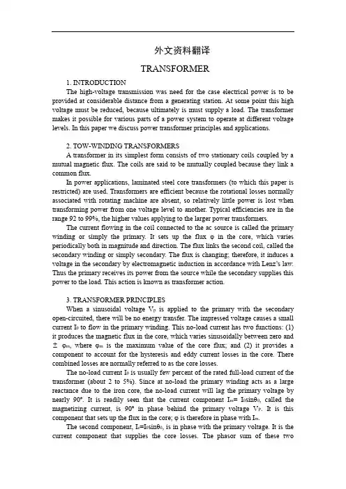
外文资料翻译TRANSFORMER1. INTRODUCTIONThe high-voltage transmission was need for the case electrical power is to be provided at considerable distance from a generating station. At some point this high voltage must be reduced, because ultimately is must supply a load. The transformer makes it possible for various parts of a power system to operate at different voltage levels. In this paper we discuss power transformer principles and applications.2. TOW-WINDING TRANSFORMERSA transformer in its simplest form consists of two stationary coils coupled by a mutual magnetic flux. The coils are said to be mutually coupled because they link a common flux.In power applications, laminated steel core transformers (to which this paper is restricted) are used. Transformers are efficient because the rotational losses normally associated with rotating machine are absent, so relatively little power is lost when transforming power from one voltage level to another. Typical efficiencies are in the range 92 to 99%, the higher values applying to the larger power transformers.The current flowing in the coil connected to the ac source is called the primary winding or simply the primary. It sets up the flux φ in the core, which varies periodically both in magnitude and direction. The flux links the second coil, called the secondary winding or simply secondary. The flux is changing; therefore, it induces a voltage in the secondary by electromagnetic induction in accordance with Lenz’s law. Thus the primary receives its power from the source while the secondary supplies this power to the load. This action is known as transformer action.3. TRANSFORMER PRINCIPLESWhen a sinusoidal voltage V p is applied to the primary with the secondary open-circuited, there will be no energy transfer. The impressed voltage causes a small current Iθ to flow in the primary winding. This no-load current has two functions: (1) it produces the magnetic flux in the core, which varies sinusoidally between zero and φm, where φm is the maximum value of the core flux; and (2) it provides a component to account for the hysteresis and eddy current losses in the core. There combined losses are normally referred to as the core losses.The no-load current Iθ is usually few percent of the rated full-load current of the transformer (about 2 to 5%). Since at no-load the primary winding acts as a large reactance due to the iron core, the no-load current will lag the primary voltage by nearly 90º. It is readily seen that the current component I m= I0sinθ0, called the magnetizing current, is 90º in phase behind the primary voltage V P. It is this component that sets up the flux in the core; φ is therefore in phase with I m.The second component, I e=I0sinθ0, is in phase with the primary voltage. It is the current component that supplies the core losses. The phasor sum of these twocomponents represents the no -load current, ore m o I I I +=It should be noted that the no -load current is distortes and nonsinusoidal. This is the result of the nonlinear behavior of the core material.If it is assumed that there are no other losses in the transformer, the induced voltage In the primary, E p and that in the secondary, E s can be shown. Since the magnetic flux set up by the primary winding ,there will be an induced EMF E in the secondary winding in accordance with Faraday’s law, namely, t N E ∆∆⋅=/ϕ. This same flux also links the primary itself, inducing in it an EMF, E p . As discussed earlier, the induced voltage must lag the flux by 90º, therefore, they are 180º out of phase with the applied voltage. Since no current flows in the secondary winding, E s =V s . The no -load primary current I 0 is small, a few percent of full -load current. Thus the voltage in the primary is small and V p is nearly equal to E p . The primary voltage and the resulting flux are sinusoidal; thus the induced quantities E p and E s vary as a sine function. The average value of the induced voltage given byE avg = turns× change in flux in a given time given timewhich is Faraday’s law applied to a finite time interval. It follows thatE avg = N 21/(2)m f ϕ = 4fNφm which N is the number of turns on the winding. Form ac circuit theory, the effective or root -mean -square (rms) voltage for a sine wave is 1.11 times the average voltage; thusE = 4.44fNφmSince the same flux links with the primary and secondary windings, the voltage per turn in each winding is the same. HenceE p = 4.44fN p φmandE s = 4.44fN s φmwhere E p and Es are the number of turn on the primary and secondary windings, respectively. The ratio of primary to secondary induced voltage is called the transformation ratio. Denoting this ratio by a, it is seen that a = p sE E = p s N N Assume that the output power of a transformer equals its input power, not a bad sumption in practice considering the high efficiencies. What we really are saying is that we are dealing with an ideal transformer; that is, it has no losses. ThusP m = P outorV p I p × primary PF = V s I s × secondary PFwhere PF is the power factor. For the above -stated assumption it means that the power factor on primary and secondary sides are equal; thereforeV p I p = V s I sfrom which is obtained p s V V = p s I I ≌ p sE E ≌ a It shows that as an approximation the terminal voltage ratio equals the turns ratio. The primary and secondary current, on the other hand, are inversely related to the turns ratio. The turns ratio gives a measure of how much the secondary voltage is raised or lowered in relation to the primary voltage. To calculate the voltage regulation, we need more information.The ratio of the terminal voltage varies somewhat depending on the load and its power factor. In practice, the transformation ratio is obtained from the nameplate data, which list the primary and secondary voltage under full -load condition.When the secondary voltage V s is reduced compared to the primary voltage, the transformation is said to be a step -down transformer: conversely, if this voltage is raised, it is called a step -up transformer. In a step -down transformer the transformation ratio a is greater than unity (a>1.0), while for a step -up transformer it is smaller than unity (a<1.0). In the event that a=1, the transformer secondary voltage equals the primary voltage. This is a special type of transformer used in instances where electrical isolation is required between the primary and secondary circuit while maintaining the same voltage level. Therefore, this transformer is generally knows as an isolation transformer.As is apparent, it is the magnetic flux in the core that forms the connecting link between primary and secondary circuit. In section 4 it is shown how the primary winding current adjusts itself to the secondary load current when the transformer supplies a load.Looking into the transformer terminals from the source, an impedance is seen which by definition equals V p / I p . From p s V V = p s I I ≌ p sE E ≌ a , we have V p = aV s and I p = I s /a.In terms of V s and I s the ratio of V p to I p isp p V I = /s s aV I a= 2s s a V I But V s / I s is the load impedance Z L thus we can say thatZ m (primary) = a 2Z LThis equation tells us that when an impedance is connected to the secondary side, it appears from the source as an impedance having a magnitude that is a 2 times its actual value. We say that the load impedance is reflected or referred to the primary. It is this property of transformers that is used in impedance -matching applications.译文变压器1. 介绍要从远端发电厂送出电能,必须应用高压输电。
XX大学学生毕业设计(论文)外文译文压,此直流电压进行逆变电路逆变(第二种功率变换)成正弦波电压,由低通滤波器输出;当市电中断时,蓄电池的直流电压经过升压(第三种功率变换)后,进行逆变器逆变成220V交流电压从低通滤波器输出。
上述过程历经三种功率变换,每一次功率变换都会产生约15%的功率损耗,其整机效率相当低。
2交流及电池检测电路图09-04是交流和蓄电池检测电路,电路分两部份,前部份是交流检测电路,检测市电是否断电或在额定范围之内。
比较器LM339的同相端接参考交流电压整流后的馒头波电压Va,反相端接市电整流后的馒头波电压Vd。
当输入市电在额定范围之内,电压Vd大于电压Va,比较器LM339输出低电平,使开关S1关断;当输入市电小于额定范围或停电时,电压Vd小于电压Va,比较器LM339输出高电平,使开关S1开通,于是信号电压V4加在Q8的栅源之间,Q8导通,蓄电池电压输出提供负载电流。
后部份是蓄电池检测电路,蓄电池电压E01接到光耦4N33二极管部份的阳极,通过电阻R7形成回路,三极管部份接成射极跟随器,经过电阻R4、R12和R5、R11分压后,接入时钟芯片NE555/ALD的Trig和Thresh端,当蓄电池电压在正常范围时,NE555/ALD输出低电平,开关S2关断;当蓄电池电压低于额定值时,NE555/ALD输出高电平,使开关S2开通,信号电压V5加在Q3的栅源之间,Q3导通,整流后的馒头波电压对蓄电池进行充电。
3极性反转电路图09-05是极性反转电源,其功能是把输入电压的极性取反。
MOS管Q1、Q2的共同源极接电阻R2和C1、D4的串联支路,D4的阴极接地,输入电压V3是正电压,驱动信号V1、V2是50Hz的方波。
前10ms 期间,Q1导通,V3在电阻R5上形成10ms的方波电压,同时通过D4向电容C1充电,极性上正下负;第二个10ms到来的时候,Q1截止,Q2导通,把C1的正电压端接地,二极管D3输出负电压,于是在电阻R1上得到10ms的负方波电压。
电气系统可编程序控制器中英文资料外文翻译文献英文原文Programmable controller designed for electro-pneumatic systems This project deals with the study of electro-pneumatic systems and the programmable controller that provides an effective and easy way to control the sequence of the pneumatic actuators movement and the states of pneumatic system. The project of a specific controller for pneumatic applications join the study of automation design and the control processing of pneumatic systems with the electronic design based on microcontrollers to implement the resources of the controller.1.IntroductionThe automation systems that use electro-pneumatic technology are formed mainly by three kinds of elements: actuators or motors, sensors or buttons and control elements like valves. Nowadays, most of the control elements used to execute the logic of the system were substituted by the Programmable Logic Controller(PLC).Sensors and switches are plugged as inputs and the direct control valves for the actuators are plugged as outputs. An internal program executes all the logic necessary to the sequence of the movements, simulates other components like counter, timer and control the status of the system.With the use of the PLC the project wins agility, because it is possible to create and simulate the system as many times as needed. Therefore, time can be saved, risk of mistakes reduced and complexity can be increased using the same elements.A conventional PLC, that is possible to find on the market from many companies, offers many resources to control not only pneumatic systems, but all kinds of system that uses electrical components. The PLC can be very versatile and robust to be applied in many kinds of application in the industry or even security system and automation of buildings.Because of those characteristics, in some applications the PLC offers to much resources that are not even used to control the system, electro-pneumatic system is one of this kind of application. The use of PLC, especially for small size systems, can be very expensive for the automation project.An alternative in this case is to create a specific controller that can offer the exactly size and resources that the project needs[3,4].This can be made using microcontrollers as the base of thiscontroller.The controller, based on microcontroller, can be very specific and adapted to only one kind of machine or it can work as a generic controller that can be programmed as a usual PLC and work with logic that can be changed. All these characteristics depend on what is needed and how much experience the designer has with developing an electronic circuit and firmware for microcontroller. But the main advantage of design the controller with the microcontroller is that the designer has the total knowledge of his controller, which makes it possible to control the size of the controller, change the complexity and the application of it. It means that the project gets more independence from other companies, but at the same time the responsibility of the control of the system stays at the designer hands2.Electro-pneumatic systemOn automation system one can find three basic components mentioned before ,plus a logic circuit that controls the system. An adequate technique is needed to project the logic circuit and integrate all the necessary components to execute the sequence of movements properly.For a simple direct sequence of movement an intuitive method can be used[1,5],but for indirect or more complex sequences the intuition can generate a very complicated circuit and signal mistakes. It is necessary to use another method that can save time of the project, make a clean circuit, can eliminate occasional signal overlapping and redundant circuits.The presented method is called step-by-step or algorithmic [1,5], it is valid for pneumatic and electro-pneumatic systems and it was used as a base in this work. The method consists of designing the systems based on standard circuits made for each change on the state of the actuators, these changes are called steps.Fig.1.Standard circuit for the pneumatic system.Fig.2.Standard circuit for the electro-pneumatic system.The first part is to design those kinds of standard circuits for each step, the next task is to link the standard circuits and the last part to connect the control element that receive signals from sensors, switches and the previous movement and give the air or electricity to the supply lines of each step. In Figs.1 and 2 the standard circuits are drawn for pneumatic and electro-pneumatic system [8].It is possible to see the relations with the previous and the next steps.3. The method applied inside the controllerThe result of the method presented before is a sequence of movements of the actuator that is well defined by steps. It means that each change on the position of the actuators is a new state of the system and the transition between states is called step.The standard circuit described before helps the designer to define the states of the systems and to define the condition to each change between the states. In the end of the design, the system is defined by a sequence that never chances and states that have the inputs and the outputs well defined. The inputs are the condition for the transition and the outputs are the result of the transition.All the configuration of those steps stays inside of the microcontroller and is executed the same way it was designed. The sequences of strings are programmed inside the controller with 5 bytes; each string has the configuration of one step of the process. There are two bytes for the inputs, one byte for the outputs and two more for the other configurations and auxiliary functions of the step. After programming, this sequence of strings is saved inside of a non-volatile memory of the microcontroller, so they can be read and executed.The controller task is not to work in the same way as a conventional PLC, but the purpose of it is to be an example of a versatile controller that is design for an specific area. A conventional PLC process the control of the system using a cycle where it makes an image of the inputs, execute all the conditions defined by the configuration programmed inside, and thenupdate the state of the outputs. This controller works in a different way, where it read the configuration of the step, wait the condition of inputs to be satisfied, then update the state or the outputs and after that jump to the next step and start the process again.It can generate some limitations, as the fact that this controller cannot execute, inside the program, movements that must be repeated for some time, but this problem can be solved with some external logic components. Another limitation is that the controller cannot be applied on systems that have no sequence. These limitations are a characteristic of the system that must be analyzed for each application.4. Characteristics of the controllerThe controller is based on the MICROCHIP microcontroller PIC16F877 [6,7] with 40 pins, and it has all the resources needed for this project. It ha enough pins for all the components, serial communication implemented in circuit, EEPROM memory to save all the configuration of the system and the sequence of steps. For the execution of the main program, it offers complete resources as timers and interruptions.The list of resources of the controller was created to explore all the capacity of the microcontroller to make it as complete as possible. During the step, the program chooses how to use the resources reading the configuration string of the step. This string has two bytes for digital inputs, one used as a mask and the other one used as a value expected. One byte is used to configure the outputs value. One bytes more is used for the internal timer, the analog input or time-out. The EEPROM memory inside is 256 bytes length that is enough to save the string of the steps, with this characteristic it is possible to save between 48 steps.The controller has also a display and some buttons that are used with an interactive menu to program the sequence of steps and other configurations.4.1.Interaction componentsFor the real application the controller must have some elements to interact with the final user and to offer a complete monitoring of the system resources that are available to the designer while creating the logic control of the pneumatic system:.Interactive mode of work; function available on the main program for didactic purposes, the user gives the signal to execute the step..LCD display, which shows the status of the system, values of inputs, outputs, timer and statistics of the sequence execution..Beep to give important alerts, stop, start and emergency..Leds to show power on and others to show the state of inputs and outputs.4.2. SecurityTo make the final application works property, a correct configuration to execute the steps in the right way is needed, but more then that it must offer solutions in case of bad functioning or problems in the execution of the sequence. The controller offers the possibility to configure two internal virtual circuits that work in parallel to the principal. These two circuits can be used as emergency or reset buttons and can return the system to a certain state at any time[2]. There are two inputs that work with interruption to get an immediate access to these functions. It is possible to configure the position, the buttons and the value of time-out of the system.er interfaceThe sequence of strings can be programmed using the interface elements of the controller. A computer interface can also be used to generate the user program easily. With a good documentation the final user can use the interface to configure the strings of bytes that define the steps of the sequence. But it is possible to create a program with visual resources that works as a translator to the user,it changes his work to the values that the controller understands.To implement the communication between the computer interface and the controller a simple protocol with check sum and number of bytes is the minimum requirements to guarantee the integrity of the data.4.4. FirmwareThe main loop works by reading the strings of the steps from the EEPROM memory that has all the information about the steps.In each step, the status of the system is saved on the memory and it is shown on the display too. Depending of the user configuration, it can use the interruption to work with the emergency circuit or time-out to keep the system safety. A block diagram of micro controller main program is presented.5.Example of electro-pneumatic systemThe system is not a representation of a specific machine, but it is made with some common movements and components found in a real one. The system is composed of four actuators. The actuators A,B and C are double acting and D-single acting. Actuator A advances and stays in specified position till the end of the cycle, it could work fixing an object to the next action for example(Fig.3), it is the first step. When A reaches the end position, actuator C starts his work together with B, making as many cycles as possible during the advancing of B. It depends on how fast actuator B is advancing; the speed is regulated by a flowing control valve. It was the second step. B and C are examples of actuators working together, while B pushes an objectslowly, C repeats. its work for some time.Fig.3.Time diagram of A,B,C and D actuators.When B reaches the final position, C stops immediately its cycle and comes back to the initial position. The actuator D is a single acting one with spring return and works together with the back of C, it is the third step. D works making very fast forward and backward movement, just one time. Its backward movement is the fourth step. D could be a tool to make a hole on the object.When D reaches the initial position, A and B return too, it is the fifth step.Fig.4 shows the first part of the designing process where all the movements of each step should be defined [2]. (A+)means that the actuator A moves to the advanced position and (A . )to the initial position. The movements that happen at the same time are joined together in the same step. The system has five steps.Fig.4.Step sequence of A,B,C and D actuators.These two representations of the system(Figs.3 and 4) together are enough to describe correctly all the sequence. With them is possible to design the whole control circuit with the necessary logic components. But till this time, it is not a complete system, because it is missing some auxiliary elements that are not included in this draws because they work in parallel with the main sequence.These auxiliary elements give more function to the circuit and are very important to the final application; the most important of them is the parallel circuit linked with all the others steps. That circuit should be able to stop the sequence at any time and change the state of the actuators to a specific position. This kind of circuit can be used as a reset or emergency buttons.The next Figs.5 and 6 show the result of using the method without the controller. Thesepictures are the electric diagram of the control circuit of the example, including sensors, buttons and the coils of the electrical valves.Fig.5.Electric diagram of the example.Fig.6.Electric diagram of the example.The auxiliary elements are included, like the automatic/manual switcher that permit a continuous work and the two start buttons that make the operator of a machine use their two hands to start the process, reducing the risk of accidents.6. Changing the example to a user programIn the previous chapter, the electro-pneumatic circuits were presented, used to begin thestudy of the requires to control a system that work with steps and must offer all the functional elements to be used in a real application. But, as explained above, using a PLC or this specific controller, the control becomes easier and the complexity can be increase also.It shows a resume of the elements that are necessary to control the presented example.With the time diagram, the step sequence and the elements of the system described in Figs.3 and 4 it is possible to create the configuration of the steps that can be sent to the controller.While using a conventional PLC, the user should pay attention to the logic of the circuit when drawing the electric diagram on the interface (Figs.5and 6), using the programmable controller, describe in this work, the user must know only the concept of the method and program only the configuration of each step.It means that, with a conventional PLC, the user must draw the relation between the lines and the draw makes it hard to differentiate the steps of the sequence. Normally, one needs to execute a simulation on the interface to find mistakes on the logic.The new programming allows that the configuration of the steps be separated, like described by the method. The sequence is defined by itself and the steps are described only by the inputs and outputs for each step.The structure of the configuration follows the order:1-byte: features of the step;2-byte: for the inputs;3-byte: value expected on the inputs;4-byte: value for the outputs;5-byte: value for the extra function.Fig.7.Actuators A and B, and sensors.Fig.8.Actuators C and D, and sensors.Table 5 shows how the user program is saved inside the controller, this is the program that describes the control of the example shown before.The sequence can be defined by 25 bytes. These bytes can be divided in five strings with 5 bytes each that define each step of the sequence (Figs.7 and 8).7. ConclusionThe controller developed for this work shows that it is possible to create a very useful programmable controller based on microcontroller. External memories or external timers were not used in case to explore the resources that the microcontroller offers inside. Outside the microcontroller, there are only components to implement the outputs, inputs, analog input, display for the interface and the serial communication.Using only the internal memory, it is possible to control a pneumatic system that has a sequence with 48 steps if all the resources for all steps are used, but it is possible to reach sixty steps in the case of a simpler system.The programming of the controller does not use PLC languages, but a configuration that is simple and intuitive. With electro-pneumatic system, the programming follows the same technique that was used before to design the system, but here the designer works directly with the states or steps of the system.With a very simple machine language the designer can define all the configuration of the step using four or five bytes. It depends only on his experience to use all the resources of the controller.The controller task is not to work in the same way as a commercial PLC but the purpose of it is to be an example of a versatile controller that is designed for a specific area. Because of that, it is not possible to say which one works better; the system made with microcontroller is an alternative that works in a simple way.References[1]E.Nelli Silva,Fluid-mechanics systems Manual, Escola Politecnica USP,2002(in Portuguese).[2]J.Swider,Control and Automation of Technological Process and Mechatronic systems,Silesian University Publishing Company,Gli-wice,2002(redaction in Polish).[3]J.Swider, G.Wszolek, W.Carvalho. Example of the system prepared to be controlled by the controller based on microcontroller,in:12 International Scientific Conference—Achievements in Mechanical and MaterialsEngineering,Gliwice-Zakopane,Poland,2003,pp.965-970.[4]J.Swider,G.Wszolek,W.Carvalho, Controller based on microcontroller designed to execute the logic control of pneumatic systems, in:12International Scientific Conference—Achievements in Mechanical and Materials Engineering,Gliwice-Zakopane,Poland,2003,pp. 959–964.[5]J.Swider,G.Wszoek, The methodical collection of laboratory and project tasks of technological process control in Pneumatic and Electro-pneumatic Systems with Logical PLC Control, Silesian University Publishing Company,Gliwice,2003.[6]PIC 16f87xDatasheet.MICROCHIP,2001.[7]Application notes AN587 and AN546.MICROCHIP,1997.[8]Fundamental of electro-pneumatic—FESTODidactic,2000.中文翻译应用于电气系统的可编程序控制器摘要此项目主要是研究电气系统以及简单有效的控制气流发动机的程序和气流系统的状态。
附录AA few examples will refresh your memory about the content of Chapter 8 and thegeneral approach to a nodal-analysis solution.EXAMPLE 17.12 Determine the voltage across the inductor for the network of Fig.Solution:Steps 1 and 2 are as ndicated in Fig.17.22.Step 3:Note Fig.17.23 for the application of Kirchhoff ’s current law to node V1:Fig.17.22 Fig.17.23∑Ii=∑I0 0=I1+I2+I3V1-E/Z1+(V1/Z2)+(V1-V2)/Z3=0Rearranging terms: V1[1/Z1+1/Z2+1/Z3]-V2[1/Z3]=E1/Z1 (17.1)Note Fig.17.24 for the application of Kirchhoff ’s current law to node V2:0=I3+I4+IV2-V1/Z3+V2/Z4+I=0Rearranging terms: V2[1/Z3+1/Z4]-V1[1/Z3]=-I (17.2)Fig.17.24Grouping equations: V1[1/Z1+1/Z2+1/Z3]-V2[1/Z3]=E1/Z1V1[1/Z3]-V2[1/Z3+1/Z4] =I1/Z1+1/Z2+1/Z3=1/0.5k Ω+1/10 k Ω+1/2k Ω=2.5mS ∠-2.29°1/Z3+1/Z4=1/2k Ω+1/-5k Ω=0.539mS ∠21.80°and V1[2.5ms ∠-2.29°]-V2[0.5mS ∠0°]=24m Α∠0°V1[0.5mS ∠0°]-V2[0.539mS ∠21.80°]=4m Α∠0°with 24m Α∠0° -0.5mS ∠0°4mΑ∠0°-0.539mS∠21.80°V1= 2.5ms∠-2.29°-0.5mS∠0°0.5mS∠0°-0.539mS∠21.80°=(24mΑ∠0°)(-0.539mS∠21.80°)+(0.5mS∠0°)(4mΑ∠0°)/[(2.5ms∠-2.29°)(-0.539mS∠21.80°)+(0.5mS∠0°)(0.5mS∠0°)]=-10.01ν-j4.81ν/-1.021-j0.45=11.106ν∠-154.33°/1.116∠-156.21°V1=9.95∠1.88°MathCad The length and complexity of the above mathematical development strongly suggest the use of an alternative approach such as MathCad.Note in MathCad 17.2 that the equations are entered in the same format as Eqs.(17.1) and (17.2).Both V1 and V2 were generated,but because only V1 was asked for,it was the only solution converted to the polar form.In the lower solution the complexity was significantly reduced by simply recognizing that the current is in milliamperes and the impedances in kilohms. The result will then be in volts.K :=10³m :=0.01 rad :=1V1 :=1+j V2 :=1+j deg :=π/180GivenV1·[1/5·k+1/10j·k+1/2·k]-V2·1/2·k≈24·mV1·[1/2·k]-V2[1/2·k+1/-5j·k]≈4·mFind(V1,V2)= 9.944 +0.319j Volts1.786 -0.396j VoltsV1 :=9.944+0.319j V1 =9.949 arg(V1)=1.837·degRecognizing that current in mA results ehen Z is in kilohmns,an alternative format follows:GivenV1·[1/5+1/10j+1/2]-V2·1/2≈24V1·1/2-V2[1/2+1/-5j]≈4Find(V1,V2)= 9.944 +0.319j Volts1.786 -0.396j VoltsV1 :=9.944+0.319j V1 =9.949 arg(V1)=1.837·degMATHCAD 17.2Dependent Current Sources For dependent current sources,the procedure is modified as follows:Steps 1 and 2 are the same as those applied for independent sources.Step 3 is modified as follows:Treat each dependent current source like an independent source when Kirchhoff’s current law applied to each defined node.However,once the equations are established,substitute the equation for the controlling quantity to ensure that the unknowns are limited solely to the chosen nodal voltages.1.Step 4 is as before.EXAMPLE 17.13 Write the nodal equations for the network of Fig.17.25 having a dependent current source.Solution: Steps 1 and 2 are as defined in Fig.17.25.Fig.17.25.Step 3: At node V1, I=I1+I2V1/Z1+V1-V2/Z2-I=0and V1[1/Z1+1/Z2]-V2[1/Z2]=IAt node V2, I2+I3+ΚI=0V2-V1/Z2+V2/Z3+Κ[V1-V2/Z2]=0and V1[1-Κ/Z2]-V2[1-Κ/Z2+1/Z3]=0resulting in two equations and two unknowns.Independent Voltage Sources between Assigned Nodes For independent voltage sources between assigned nodes,the procedure is modified as follows:1.Steps 1 and 2 are the same as those applied for independent sources.2.Step 3 is modefied as follows:Treat each source betwwen defined nodes as ashort circuit(recall the supernode classification of Chapter 8),and write the nodal equations for each remaining independent node.Then relate the chosen nodal voltages to the independent voltage source to ensure that the unknowns of the ginal equations are limited solely to the nodal voltages.3.Step 4 is as before.EXAMPLE 17.14 Write the nodal equations for the network of Fig.17.26 having an independent source between two assigned nodes.Solution: Steps 1 and 2 defined in Fig.17.26.Step 3:Replacing the independent source E with a short-circuit equivalent results in a supernode that will generate the following equation when Kirchhoff’s current law is applied to node V1: I1=V1/Z1+V2/Z2+I2with V2-V1=EFig.17.26.and we have two equationsand two unknowns.Dependent Voltage Source between Defined Nodes For dependent voltage sources between defined nodes,the procedure is modified as follows:1.Steps 1 and 2 are the same as those applied for independent voltage sources.2.Step 3 is modified as follows:The procedure is essentially the same as thatapplied for independent voltage sources,except now the dependent sourcess having to be defined in terms of the chosen nodal voltage to ensure that the final equations have only nodal voltage as their unknown quantities.3.Step 4 is as before.EXAMPLE 17.15Write the nodal equations for the network of Fig.17.27 having a dependent voltage source between two defined nodes.Solution: Steps 1 and 2 are defined in Fig.17.27.Fig.17.27.Step 3:Replacing the dependent source μVx with a short-circuit equivalent will result in the following equation when Kirchhoff's current law is applied at node V1:I=I1+I2V1/Z1+(V1-V2)/Z2-I=0and V2=μVx=μ[V1-V2]or V2=μV1/1+μresulting in two equations and two unknowns.Note that because the impedance Z3 is in parallelwith a voltage source,it does not appear in the analysis.It will,however,affect the current through the dependent voltage source.Format ApproachA close examination of Eqs.(17.1) and (17.2) in Example 17.12 will reveal thatthey are the same equations that would have been obtained using the format approach introduce in Chapter 8.Recall that the approach required that the voltage source first be converted to a current source,but the writing of the equations was quite direct and minimized any chances of an error due to lost sign or missing term.The sequence of steps required to apply the format approach is the following:1.Choose a reference node and assign a subscripted voltage lable to the(N-1)remaining independent nodes of the network.2.The number of equations required for a complete solution is equal to the numberof subcripted voltages(N-1).Column 1 of each equation is formed by summing the admittances tied to the node of interest and multiplying the result by that subscripted nodal voltage.3.The mutual terms are always subtracted from the terms of the first column.It ispossible to have more than one mutual term if the nodal voltage of interest has an element in common with more than one other nodal voltage.Each mutual term is product of the mutual admittance and the other nodal voltage tied to that admittance.4.The column to the right of the equality sign is the algebraic sum of the currentsources tied to the node of interest.A current source is assigned a positive sign if it supplies current to a node,and a negative sign if it draws current from the node. Solve resulting simultaneous equations for the desired nodal voltages.The comments offered for mesh analysis regarding independent and dependent sources apply here also.EXAMPLE 17.16Using the format approach to nodal analysis,find the voltage across the 4-Ωresistor in Fig.17.28.Fig.17.28.Solution: Choosing nodes(Fig.17.29) and writing the nodal equations,we have Z1=R=4ΩZ2=jXl=j5ΩZ3=-jXc=-j2ΩFig.17.29V1(Y1+Y2)-V2(Y2)=-I1V2(Y3+Y2)-V1(Y2)=+I2or V1(Y1+Y2)-V2(Y2)=-I1-V1(Y2)+V2(Y3+Y2)=+I2Y1=1/Z1 Y2=1/Z2 Y3=1/Z3Using determinants yields-I1 -Y2+I2 Y2+Y3V1 = =-(Y3+Y2)I1+I2Y2/(Y1+Y2)(Y3+Y2)-Y2Y2Y1+Y2 -Y2-Y2 Y3+Y2=-(Y3+Y2)I1+I2Y2/Y1Y3+Y2Y3+Y1Y2Substituting numerical values,we haveV1=-[(1/-j2Ω)+(1/j5Ω)]6Α∠0°+4Α∠0°(1/j5Ω)/(1/4Ω)(1/-j2Ω)+(1/j5Ω)(1/-j2Ω)+(1/4Ω)(1/j5Ω)=-(+j0.5-j0.2)6∠0°+4∠0°(-j0.2)/(1/j8)+(1/10)+(1/j20)=(-0.3∠90°)(6∠0°)+4∠0°(-j0.2)/j0.125+0.1-j0.05=-1.8∠90°+0.8∠-90°/0.1+j0.075=2.6ν∠-90°/0.125∠36.87°V1=20.80ν∠-126.87°MathCad Using MathCad and the matrix format with the admittance parameters will quickly provide a solution for V1 in Example 17.16,as shown in MathCad 17.3.Z1 :=4 Z2 :=5j Z3 :=-2j rad :=1 deg :=π/180Y := [1/Z1+1/Z2] -1/Z2 I := -6 -1/Z2 [1/Z2+1/Z3] 4I/Y= -12.48 -16.64j Volts8.32 -2.24j VoltsV1 := -12.48 -16.64j V1=20.8 arg(V1)=-126.87·degV2 := 8.32 -2.24j V2=8.616 arg(V2)=-15.068·degMATHCAD 17.3EXAMPLE 17.17 Using the format approach,write the nodal equations for the network of Fig.17.30.Fig.17.30.Solution: The circuit is redrawn in Fig.17.31,whereZ1=R1+jXl1=7Ω+j8ΩE1=20ν∠0°Z3=-jXc=-j10ΩZ2=R2+jXl2=4Ω+j5ΩI1=10Α∠20°Z4=R3=8ΩConverting the voltage source to a current source and choosing nodes,we obtain Fig.17.32.Note the “neat”appearance of the network using the subscripted impedances.Working directly with Fig.17.30would be more difficult and could produce errors.Write the nodal equations: V1(Y1+Y2+Y3)-V2(Y3)=+I2V2(Y3+Y4)-V1(Y3)=+I1Y1=1/Z1 Y2=1/Z2 Y3=1/Z3 Y4=1/Z4 which are rewritten as V1(Y1+Y2+Y3)-V2(Y3)=+I2-V1(Y3)+V2(Y3+Y4)=+I1EXAMPLE 17.18 Write the nodal equations for the network of Fig.17.33.Do not solve.Solution: Choose nodes(Fig.17.34): Z1=R1 Z2=jXl1 Z3=R2-jXc2Z4=-jXc1 Z5=R3 Z6=jXl2 and write the nodal equations: V1(Y1+Y2)-V2(Y2)=+I1V2(Y2+Y3+Y4)-V1(Y2)-V3(Y4)=-I2V3(Y4+Y5+Y6)-V2(Y4)=+I2which are rewritten as V1(Y1+Y2)-V2(Y2)+0=+I1-V1(Y2)+ V2(Y2+Y3+Y4)-V3(Y4)=-I20-V2(Y4)+V3(Y4+Y5+Y6)=+I2Y1=1/R1 Y2=1/jXl1 Y3=1/R2-jXc2 Y4=-1/jXc1 Y5=1/R3 Y6=1/jXl2Fig.17.31Note the symmetry about the diagonal for this example and those preceding it in this section.EXAMPLE 17.19Apply nodal analysis to the network of Fig.17.35.Determine the voltage Vl.Solution: In this case there is no need for a source conversion.The network is redrawn in Fig.17.36 with the chosen nodal voltage and subscripted impedances.Apply the format approach: Y1=1/Z1=1/4kΩ=0.25mS∠0°= G1∠0°Y2=1/Z2=1/1kΩ=1mS∠0°= G1∠0°Y3=1/Z3=1/2kΩ∠90°=0.5mS∠-90°=-j0.5mS=-jBlV1: (Y1+Y2+Y3)V1=-100Iand V1=-100I/Y1+Y2+Y3=-100I/0.25mS+1mS-j0.5mS=-100×10³I/1.25-j0.5=-100×10³I/1.3463∠-21.80°=-74.28×10³I∠21.80°=-74.28×10³I(Vi/1kΩ)∠21.80°V1=Vl=-(74.28Vi)V∠21.80°17.6 BRIDGE NETWORKS(ac)The basic bridge figuration was discussed in some detali in Section 8.11 for dc networks.We now continue to examine bridge networks by considering those that have reactive components and a sinusoidal ac voltage or current applied.We will first analyze various familiar forms of the bridge network using mesh analysis and nodal analysis(the format approach).The balance conditions will be investigated throughout the section.Apply mesh analysis to the network of Fig.17.37.The network is redrawn in Fig.17.38,where Z1=1/Y1=1/G1+jBc=G1/(G1²+Bc ²)-jBc/( G1²+Bc²)Z2=R2 Z3=R3 Z4=R4+jXl Z5=R5Applying the format approach: (Z1+Z3)I1-(Z1)I2-(Z3)I3=EFig.17.32(Z1+Z2+Z5)I2-(Z1)I1-(Z5)I3=0(Z3+Z4+Z5)I3-(Z3)I1-(Z5)I2=0which are rewritten as (Z1+Z3)I1-(Z1)I2-(Z3)I3=E-(Z1)I1+(Z1+Z2+Z5)I2-(Z5)I3=0-(Z3)I1-(Z5)I2+(Z3+Z4+Z5)I3=0Note the symmetry about the diagonal of the above equations.For balabce,Iz5=0Α,andIz5=I2-I3=0From the above equations,Z1+Z3 E -Z3-Z1 0 -Z5-Z3 0 (Z3+Z4+Z5)I2==E(Z1Z3+Z1Z4+Z1Z5+Z3Z5)/ΔZ1+Z3 -Z1 -Z3-Z1 (Z1+Z2+Z5) -Z5-Z3 -Z5 (Z3+Z4+Z5)where Δsignifies the determinant of the denominator(or coefficients).Similarly,I3=E(Z1Z3+Z3Z2+Z1Z5+Z3Z5)/Δand Iz5=I2-I3=E(Z1Z4-Z3Z2)/ΔFor Iz5=0,the following must be satisfied(for a finite Δnot equal to zero):Z1Z1= Iz5=0 (17.3)This condition will be analyzed in greater depth later in this section.举几个例子就刷新你对第8章的内容和一般方法一节点,分析解决内存。
中英文资料外文翻译文献原文:A SPECIAL PROTECTION SCHEME FOR VOLTAGESTABILITY PREVENTIONAbstractVoltage instability is closely related to the maximum load-ability of a transmission network. The energy flows on the transmission system depend on the network topology, generation and loads, and on the availability of sources that can generate reactive power. One of the methods used for this purpose is the Voltage Instability Predictor (VIP). This relay measures voltages at a substation bus and currents in the circuit connected to the bus. From these measurements, it estimates the Thévenin’s equivalent of the network feeding the substation and the impedance of the load being supplied from the substation. This paper describes an extension to the VIP technique in which measurements from adjoining system buses and anticipated change of load are taken into consideration as well.Keywords: Maximum load ability; Voltage instability; VIP algorithm.1.IntroductionDeregulation has forced electric utilities to make better use of the available transmission facilities of their power system. This has resulted in increased power transfers, reduced transmission margins and diminished voltage security margins.To operate a power system with an adequate security margin, it is essential to estimate the maximum permissible loading of the system using information about the current operation point. The maximum loading of a system is not a fixed quantity but depends on various factors, such as network topology, availability of reactive power reserves and their location etc. Determining the maximum permissible loading, within the voltage stability limit, has become a very important issue in power system operation and planning studies. The conventional P-V or V- Q curves are usually used as a tool for assessing voltage stability and hence for finding the maximum loading at the verge of voltage collapse [1]. These curves are generated by running a large number of load flow cases using, conventional methods. While such procedures can be automated, they are time-consuming and do not readily provide information useful in gaining insight into the cause of stability problems [2].To overcome the above disadvantages several techniques have been proposed in the literature, such as bifurication theory [3], energy method [4], eigen value method [5],multiple load flow solutions method [6] etc.Reference [7] proposed a simple method, which does not require off-line simulation and training. The Voltage Indicator Predictor (VIP) method in [7] is based on local measurements (voltage and current) and produces an estimate of the strength / weakness of the transmission system connected to the bus, and compares it with the local demand. The closer the local demand is to the estimated transmission capacity, the more imminent is the voltage instability. The main disadvantage of this method is in the estimation of the Thévenin’s equivalent, which is obtained from two measurements at different times. For a more exact estimation, one requires two different load measurements.This paper proposes an algorithm to improve the robustness of the VIP algorithm by including additional measurements from surrounding load buses and also taking into consideration local load changes at neighboring buses.2. Proposed MethodologyThe VIP algorithm proposed in this paper uses voltage and current measurements on the load buses and assumes that the impedance of interconnecting lines (12Z ,13Z ) are known, as shown in (Figure 1). The current flowing from the generator bus to the load bus is used to estimate Thévenin’s equivalent for the system in that direction. Similarly the current flowing from other load bus (Figure 2) is used to estimate Thévenin’s equivalent from other direction. This results in following equations (Figure 3). Note that the current coming from the second load bus over the transmission line was kept out of estimation in original (VIP) algorithm.)()()(111112211111----=-+th th th L Z E Z V Z Z V [1] )()()(122112112122----=-+th th th L Z E Z V Z Z V [2] 1111111)()(E th th th I Z V Z E =--- [3] 2122122)()(E th th th I Z V Z E =--- [4] Where 1E I and 2E I are currents coming from Th évenin buses no.1 and 2. Equation (1)-(4) can be combined into a matrix form:⎥⎥⎥⎥⎥⎦⎤⎢⎢⎢⎢⎢⎣⎡---++---++-------------121211111212112121-12111121111211000000th th th th th th L th th L Z Z Z Z Z Z Z Z Z Z Z Z Z Z *=⎥⎥⎥⎥⎦⎤⎢⎢⎢⎢⎣⎡2121th th E E V V ⎥⎥⎥⎥⎦⎤⎢⎢⎢⎢⎣⎡2100E E I I [5] Using the first 2 rows in the system Equations (1)-(4), the voltage on buses number 1 and 2 can be found as shown in Equation (6) below. From Equation (6) wecan see that the voltage is a function of impedances. Note that the method assumes that all Thévenin’s parameters are constant at the time of estimation.⎥⎥⎦⎤⎢⎢⎣⎡⎥⎥⎦⎤⎢⎢⎣⎡++--++=⎥⎦⎤⎢⎣⎡-----------12211111121212112112112111121*th th th th th L th L Z E Z E Z Z Z Z Z Z Z Z V V [6] Where, 111-=L Z y 11212-=Z y and 122-=L Z yThe system equivalent seen from bus no.1 is shown in Figure 3. Figure 4(a) shows the relationship between load admittances (1y and 2y ) and voltage at bus no.1. Power delivered to bus no.1 is (1S ) and it is a function of (1L Z ,2L Z ).1211*L y V S = [7]Equation 7 is plotted in figure 4 (b) as a ‘landscape’ and the maximum loading point depends on where the system trajectory ‘goes over the hill’.Fig. 1. 3-Bus system connections Fig. 2. 1-Bus modelFig. 3. System equivalent as seen by the proposed VIP relay on bus #1 (2-bus model)(a)Voltage Profile (b) Power ProfileFig. 4. Voltage and power profiles for bus #12.1. On-Line Tracking of Thévenin’s ParametersThévenin’s parameters are the main factors that decide the maximum loading of the load bus and hence we can detect the voltage collapse. In Figure3, th E can be expressed by the following equation:I Z V E th load th += [8]V and I are directly available from measurements at the local bus. Equation (8) can be expressed in the matrix form as shown below.⎥⎥⎥⎥⎦⎤⎢⎢⎢⎢⎣⎡--⎥⎥⎥⎥⎦⎤⎢⎢⎢⎢⎣⎡=⎥⎥⎥⎥⎦⎤⎢⎢⎢⎢⎣⎡000010000001)()(00..r i i r th th th th i r I I I I X R i E r E V V [9] B= A X [10] The unknown parameters can be estimated from the following equation:B A AX A T T = [11] Note that all of the above quantities are functions of time and are calculated on a sliding window of discrete data samples of finite, preferably short length. There are additional requirements to make the estimation feasible:• There must be a significant change in load impedance in the data window of at least two set of Measurements.• For small changes in Thévenin’s parameters within a particular data window, the algorithm can estimate properly but if a sudden large change occurs then the process of estimation is postponed until the next data window comes in.• The monitoring device based on the above principle can be used to impose a limit on the loading at each bus, and sheds load when the limit is exceeded. It can also be used to enhance existing voltage controllers. Coordinated control canalso be obtained if communication is available.Once we have the time sequence of voltage and current we can estimate unknowns by using parameter estimation algorithms, such as Ka lm an Filtering approach described [6].stability margin (VSM) due to impedances can be expressed as (Z VSM ); where subscript z denotes the impedance.Therefore we have: Load thev Load Z Z Z Z VSM -= [12] The above equation assumes that both load impedances (1Z , 2Z ) are decreasing at a steady rate, so the power delivered to bus 1 will increase according to Equation(7). However once it reaches the point of collapse power starts to decrease again.Now assume that both loads are functions of time. The maximum critical loading point is then given by Equation(13):011==dtds S Critical [13] Expressing voltage stability margin due to load apparent power as ( S VSM ), we have:Critical Load Critical S SS S VSM -= [14] Note that both Z VSM and S VSM are normalized quantities and their values decrease as the load increases.At the voltage collapse point, both the margins reduce to zero and the corresponding load is considered as the maximum permissible loading.Fig. 5. VIP algorithm2.2. Voltage Stability Margins and the Maximum Permissible LoadingSystem reaches the maximum load point when the condition: thev load Z Z =is satisfied (Figure5).Therefore the voltage stability boundary can be defined by a circlewith a radius of the Thévenin’s impedance. For normal operation the thev Z is smaller than load Z (i.e. it is outside the circle) and the system operates on the upper part (or the stable region) of a conventional P-V curve [2].However, when thev Z exceeds load Z the system operates on the lower part (or unstable region) of the P-V curve, indicating that voltage collapse has already occurred. At the maximum power point, the load impedance becomes same as the Thévenin’s (thev L Z Z ). Therefore, for a given load impedance (load Z ), the difference between thev Z and load Z can be considered as a safety margin. Hence the voltage as given in an IEEE survey, which described (111) schemes from (17) different countries [8].Fig. 6. Load actions to prevent from voltage instability2.3. Advantages of the proposed VIP algorithmBy incorporating the measurements from other load buses (Figure 3), the proposed VIP algorithm achieves a more accurate value of load Z . The on-line tracking of thev Z is used to track system changes.The proposed improvements in the VIP algorithm will result in better control action for power system voltage stability enhancement. The control measures are normally shunt reactor disconnection, shunt capacitor connection, shunt V ARcompensation by means of SVC’s and synchrouns condensers, starting of gas turbines, low priority load disconnection, and shedding of low-priority load [8]. Figure 6 shows the most commonly used remedial actions .3. ConclusionsAn improved V oltage Instability Predictor (VIP) algorithm for improving the voltage stability is proposed in this paper. The previous VIP method [7] used measurements only from the bus where the relay is connected. The new method uses measurements from other load buses as well. The voltage instability margin not only depends on the present state of the system but also on future changes.Therefore, the proposed algorithm uses an on-line tracking Thévenin’s equivalent for tracking the system trajectory. The algorithm is simple and easy to implement in a numerical relay. The information obtained by the relay can be used for load shedding activation at the bus or V AR compensation. In addition, the signal may be transmitted to the control centre,where coordinated system-wide control action can be undertaken. The algorithm is currently being investigated on an IEEE 30 bus system and results using the improved VIP algorithm will be reported in a future publication. References[1] M.H.Haque, “On line monitoring of maximum permissible loading of a power system within voltage stability limits”, IEE proc. Gener. Transms. Distrib.,V ol. 150, No. 1, PP. 107-112, January, 2003[2] V. Balamourougan, T.S. Sidhu and M.S. Sachdev, “Technique for online prediction of voltage collapse”, IEE Proc.Gener.Transm. Distrib., V ol.151, No. 4, PP. 453-460, July, 2004[3] C.A. Anizares, “On bifurcations voltage collapse and load modeling “IEEE Trans. Power System, V ol. 10, No. 1, PP. 512-522, February, 1995[4] T.J Overbye and S.J Demarco, “Improved Technique for Power System voltage stability assessment using energy methods“, IEEE Trans. Power Syst., Vol. 6, No. 4, PP. 1446-1452, November, 1991[5] P.A Smed Loof. T. Andersson, G. Hill and D.J,”Fast calculation of voltage stability index”, IEEE Trans. Power Syst. V ol. 7, No. 1, PP. 54-64, February, 1992[6] K. Ohtsuka ,” An equivalent of multi- machine power system and its identification for on-line application to decentralized stabilizers”, IEEE Trans. Power Syst., V ol. 4 No. 2, PP. 687-693, May, 1989[7] Khoi Vu, Miroslav M Begovic, Damir Novosel, Murari Mohan Saha, “ Use of local Measurements to estimate voltage –stability margin “ IEEE Trans. Power syst. Vol. 14, No. 3, PP. 1029-1035, August, 1999[8] G.V erbic and F. Gubina “Fast voltage-collapse line protection algorithm based on local phasors”, IEE Proc.Gener.Transm. Distrib., V ol. 150, No. 4, PP. 482-486, July, 2003译文:一种特殊的预防电压波动的保护方案摘要电压的波动与输电线路的最大负载能力密切相关。
XXXX大学(外文翻译材料)学院:专业:学生姓名:指导教师:BLDC Motor Speed Estimation Using PDC Timer Module1 Speed Calculation of BLDC1.1 Summary of BLDCSince current BLDC has substituted the electrical commutator for the mechanical one, it eliminates the disadvantages of noise, spark, electromagnetic disturbance, short lifetime, etc. Now BLDC is provided with advantages of simple structure, dependable operation and easy maintenance as AC motor does, as well as advantages of high efficient, no excitation cost and functional speed regulation as traditional DC motor does. So it is widely used in various fields of industrial control now.1.2 PDC Module IntroductionSPMC75F2413A provides two channels of 16 bit PDC (Phase Detection Control, PDC) timers used for capture function and PWM operation. It also supports position detection features for Brushless-DC motor application. The PDC timers are very suitable for both mechanical speed calculation, with ACI and BLDC motor included, and phase commutation for changing current conduction according to position information. Figure1-1 shows the block diagram of entire PDC timers, channel 0 and channel 1. For details of PDC timer’s specificati on, please refer to Table 1-1.Table 1-1 PDC TimerFunction PDC Timer 0 PDC Timer 1Clock sources Internal clock: FCK/1,FCK/4, FCK/16, FCK/64,FCK/256, FCK/1024External clock: TCLKA,TCLKBInternal clock: FCK/1,FCK/4, FCK/16,FCK/64, FCK/256,FCK/1024External clock: TCLKA,TCLKBIO pins TIO0A, TIO0B, TIO0C TIO1A, TIO1B, TIO1CTimer general register P_TMR0_TGRA,P_TMR0_TGRB,P_TMR0_TGRCP_TMR1_TGRA,P_TMR1_TGRB,P_TMR1_TGRCTimer buffer register P_TMR0_TBRA,P_TMR0_TBRB,P_TMR0_TBRCP_TMR1_TBRA,P_TMR1_TBRB,P_TMR1_TBRCTimer period and counter register P_TMR0_TPR,P_TMR0_TCNTP_TMR1_TPR,P_TMR1_TCNT1Capture sample clock Internal clock: FCK/1,FCK/2, FCK/4, FCK/8Internal clock: FCK/1,FCK/2, FCK/4, FCK/8Counting edge Count on rising, falling, bothedgeCount on rising, falling,both edgeCounter clear source Cleared on P_TMR0_TGRA,P_TMR0_TGRB,P_TMR0_TGRC captureinput.Cleared onP_POS0_DectData positiondetection data changes.Cleared on P_TMR0_TPRcompare matches.Cleared onP_TMR1_TGRA,P_TMR1_TGRB,P_TMR1_TGRC captureinput.Cleared onP_POS1_DectDataposition detection datachanges.Cleared onP_TMR1_TPR comparematches.Input capture function Yes YesPWM compare match output function 1 output Yes Yes 0 output Yes Yes OutputHoldYes YesEdge-aligned PWM Yes Yes Center-aligned PWM Yes YesPhase counting mode Yes, phase inputs areTCLKA/TCLKBYes, phase inputs areTCLK C/TCLKDTimer buffer operation Yes YesAD convert start trigger P_TMR0_TGRA comparematchP_TMR1_TGRAcompare matchInterrupt sources Timer 0 TPR interruptTimer 0 TGRA interruptTimer 0 TGRB interruptTimer 0 TGRC interruptTimer 0 PDC interruptTimer 0 overflow interruptTimer 0 underflow interruptTimer 1 TPR interruptTimer 1 TGRA interruptTimer 1 TGRB interruptTimer 1 TGRC interruptTimer 1 PDC interruptTimer 1 overflowinterruptTimer 1 underflowinterrupt2Figure 1-1 PDC Timers Block Diagram1.3 PDC OperationThis note mainly depicts PDC application in motor speed measurement. For detailed PDC introduction, please refer to “SPMC75F2413A Programming Guide” authored by Sunplus.PDC module has four types of registers to perform speed measurement: Timer control register P_TMRx_Ctrl (x = 0, 1), position detection control register P_POSx_DectCtrl (x = 0, 1), input output control register P_TMRx_IOCtrl (x = 0, 1), and timer interrupt enable register P_TMRx_INT (x = 0, 1). Where, P_TMRx_Ctrl and P_POSx_DectCtrl are introduced in detail.1.31Input Output Control RegisterP_TMRx_Ctrl(x = 0, 1)B15 B14 B13 B12 B11 B10 B9 B8R/W R/W R/W R/W R/W R/W R/W R/W30 0 0 0 0 0 0 0SPCK MODE CLEGSB7 B6 B5 B4 B3 B2 B1 B0R/W R/W R/W R/W R/W R/W R/W R/W0 0 0 0 0 0 0 0SPCK MODE CLEGSBit 15:14SPCK: Capture input sample clock select. These bits select the capture input sample clock. Capture input will be sampled with sample clock. Pulses shorter than four sample clocks will be considered invalid, and will be ignored.00 = FCK/101 = FCK/210 = FCK/411 = FCK/8Bit 13:10MODE: Modes select. These bits are used to select the timer operation modes.0000 = Normal operation (continuous counter up counting)0100 = Phase counting mode 10101 = Phase counting mode 20110 = Phase counting mode 30111 = Phase counting mode 41x0x = Edge-aligned PWM mode (continuous counter up counting, PWM output) 1x1x = Center-aligned PWM mode (continuous counter up/down counting, PWM output)Bit 9:8CLEGS: Counter clear edge select. These bits select the counter clearing edge when the clearing source is in input capture mode.00 = do not clear01 = rising edge10 = falling edge11 = both edge4Bit 7:5CCLS: Counter clear source select. These bits select the TCNT counter clearing source.000 = TCNT clearing disabled001 = TCNT cleared by P_TMRx_TGRA (x = 0, 1) capture input010 = TCNT cleared by P_TMRx_TGRB (x = 0, 1) capture input011 = TCNT cleared by P_TMRx_TGRC (x = 0, 1) capture input100 = TCNT cleared by every P_POSx_DectData (x = 0, 1) change 6 times101 = TCNT cleared by every P_POSx_DectData (x = 0, 1) change 3 times110 = TCNT cleared by P_POSx_DectData (x = 0, 1) position detection data change 111 = TCNT cleared by P_TMRx_TPR (x = 0, 1) compare matchBit 4:3CKEGS: Clock edge select, These bits select the input clock edge. When the input clock is counted using both edges, the input clock period is halved. When FCK/1 is selected as counter clock, counter will count at rising edge if count at both edges is selected.00 = Count at rising edge01 = Count at falling edge1X = Count at both edgesBit 2:0TMRPS: Timer pre-scalar select. These bits select the TCNT counter clock source. It can be selected independently for each channel.000 = Counts on FCK /1001 = Counts on FCK /4010 = Counts on FCK /16011 = Counts on FCK /64100 = Counts on FCK /256101 = Counts on FCK /1024110 = Counts on TCLKA pin input111 = Counts on TCLKB pin inputControl register configurationP_TMRx_Ctrl(x = 0, 1) is used for the selection of input capture during speed5measurement. Rather than being a general input signal, the input capture is a period between two position detection changes triggered by PDC interrupt. This period must be counted with a certain frequency supported by a clock source. Thus, the counters on this function must be configured.MODE: Select a timer operation mode in seven modes. However, only the normal operation (continuous counter up counting) mode can be selected in this application, because the other six modes are all related to phase counting mode or PWM mode.CCLS: Select a TCNT counter clearing source from eight settings. In this application, one among the three can be set: 100, 101 or 110, which respectively indicates that TCNT is cleared for once every 6/3/1 times P_the POSx_DectData (x = 0, 1) changes. Also, they can be described as: TCNT is cleared for once every 360/180/60 electrical degree rotation of BLDC. This setting is critical for converting electrical revolution to mechanical revolution and measuring the BLDC speed.CKEGS: Select the input clock edge, which can be rising, falling or both edges. When the input clock is counted using both edges, the input clock period is halved. Note to count this factor on during the BLDC speed calculation.TMRPS: Select the TCNT counter clock source from eight settings. This setting determines the precision and the range during BLDC speed measurement. See the example code below:P_TMR0_Ctrl, B.MODE = 0; // Normal Counting modeP_TMR0_Ctrl, LS = 6; // TCNT cleared by P_POSx_DectData (x = 0, 1)// Each time position detection data changeP_TMR0_Ctrl, B.CKEGS = 0; // Counting at rising edgeP_TMR0_Ctrl, B.TMRPS = 3; // Select FCK/64 clock source1.3.2 Position Detection Control RegisterP_POSx_DectCtrl(x = 0, 1)B15 B14 B13 B12 B11 B10 B9 B8R/W R/W R/W R/W R/W R/W R/W R/W0 0 0 0 0 0 0 0SPLCK SPLMOD SPLCNTB7 B6 B5 B4 B3 B2 B1 B0R/W R/W R/W R/W R/W R/W R/W R/W0 0 0 0 0 0 0 06PDEN SPDLYBit 15:14SPLCK: Sampling clock select. Select FCK/4, FCK/8, FCK/32, or FCK/128 for position sampling clock00 = FCK/401 = FCK/810 = FCK/3211 = FCK/128Bit 13:12SPLMOD: Sampling mode select. Select one of three modes: sampling when PWM signal is active (PWM is on), sampling regularly, or sampling when lower side (UN, VN, WN) phases are conducting current.00 = Sample when UPWM/VPWM/WPWM bit is set in P_TMRx_OutputCtrl (x = 3,4) register and generate the PWM waveform01 = Sample regularly10 = Sample when lower phases is in active state and conducting current11 = ReservedBit 11:8SPLCNT: Sampling count select. These bits select the sampling count for the valid external position detection signals. The position signals must be sampled continuously match as many times as the sampling count set, for the position signals to be considered valid. The valid settings are from 1 to 15 times. Note that count 0 and 1 are assumed to be one time.Bit : 7PDEN: Position detection enable. This bit enables/disables the position detection function for position input pins TIOA~C. When enabled, the input signals of these pins will be sampled and the results will be latched to PDR [2:0] bits in POS_DectData register. When disabled, PDR [2:0] will remain its status.0 = Disable1 = EnableBit 6:0SPDLY: Sampling delay. These bits set a delay time clock in which at SPLCK clock7source. It is used to stop sampling in order to prevent erroneous detection due to noise that occurs immediately after PWM output turns on.Position detection control registerWhen the position detection changing event occurs, the P_TMRx_TCNT (x = 0, 1) value can be transferred to TGRA. If the position detection interrupt enable bit PDCIE is set to 1 in the corresponding P_TMRx_INT (x = 0, 1) register, the PDC interrupt routine will be called to process the data.SPLCK: Select sampling clock from FCK/4, FCK/8, FCK/32, or FCK/128 for position sampling clock, which determines the detection precision of position change. Proper setting of SPLCK, SPLCNT and SPDLY will help to prevent erroneous detection and filter the disturbance.SPLMOD: Select one of these three modes: sampling when PWM signal is active (PWM is on), sampling regularly, or sampling when lower side (UN, VN, WN) phases are conducting current.SPLCNT: Sampling count select. The valid settings are from 1 to 15 times. Note that count 0 and 1 are both assumed to be one time.PDEN: This bit enables/disables the position detection function for position input pins TIOA~C.SPDLY: Sampling delay with the range of 0 to 127.The setting example is shown as blew.P_POS0_DectCtrl, B.SPLCK = 2; // Count on FCK/32P_POS0_DectCtrl, B.SPLMOD = 1; // Sample regularlyP_POS0_DectCtrl, B.SPLCNT = 10; // Sample 10 timesP_POS0_DectCtrl, B.PDEN = 1; // Enable position detectionP_POS0_DectCtrl, B.SPDLY = 100; // Sample Delay1.4 Speed CalculationIn order to obtain the exact parameters, the data must be filtered after captured. There are many filter algorithms, such as low-pass filter, moving average filter, median filter, average filter, limiting filtering, first-order filter, moving average filtering, etc. In general, the data can be considered valid after processed by these filters. Then the speed can be calculated by substituting these parameters data in the formula.Assume Fcap is PDC capture clock frequency; p is the pole-pair of BLDC rotor; TCNT is cleared every m P_POSx_DectData (x = 0, 1) changes, that is, TCNT is cleared at89every *3m πrad rotation (m=1, 3, 6), and the position data is NcapSince:d dt φΩ=(Formula 1- 1)and d φ=*3m π,Ncapdt Fcap = Since electrical degree = p x mechanical rotation then the mechanical angularvelocity isp ωΩ=(Formula 1- 2)with the unit of rad/min. Take n as the indicator. So:26030n nππω== rad/min (Formula 1- 3)n summarize:60**10**3*2***Fcap m Fcap mn Ncap p Ncap p ==rpm (Formula 1- 4)From the formula above, we can obverse that n is related to Fcap, m, Ncap and p (thatis a constant when BLDC is selected) .Suppose there is a BLDC with 2 pole-pair, 4000rpm rated speed. We will show you how to set the parameters of Fcap and m.When m= 1, TCNT is cleared every time P_POSx_DectData (x = 0, 1) changes, , that is, TCNT is cleared for once every 60 electrical degree rotation of BLDC.With a certain clock frequency, the motor rotation speed can be calculated by the Formula 1- 4 at the highest speed when Ncap is 1 and the lowest speed when Ncap is 0xffff.Table 1-2 Motor Speed VS Clock FrequencyFcap n FCK/1FCK/4FCK/16 FCK/64FCK/256FCK/1024Nmax (rpm) 120M 30M 7.5M 1875K 468750 117187.5 Nmin (rpm)1831457.8114.428.67.21.8@When m= 3, TCNT is cleared for once every 3 times P_POSx_DectData (x = 0, 1)10changes, that is, TCNT is cleared every 180 electrical degree rotation of BLDC. From the Formula 1- 4, we can see that the measurable motor speed when m= 3 is three times higher than that when m= 1, provided that other parameters are the same. @When m= 6, TCNT is cleared every 6 times P_POSx_DectData (x = 0, 1) changes, that is, TCNT is cleared every 360 electrical degree rotation of BLDC.From the Formula 1- 4, we can see that the measurable motor speed when m= 6 is six times higher than that when m= 1, provides that other parameters are the same.Above all, it is better to set m= 1 to ensure the veracity of positions. Since the highest speed can be applied, it is important to select the lowest speed. Assume the lowest measure speed is 200 rpm, we can set Fcap as FCK/16, FCK/64, FCK/256 or FCK/1024. FCK/16 is recommended to be selected for higher veracity. 1.5 Noise ImmunityThrough programming the bit value of SPLCNT (sampling count select) and SPDLY (sampling delay) in P_POSx_DectCtrl(x = 0, 1), users could avoid the erroneous detection due to noise that occurs immediately after PWM output turns on. It can ensure the correctness of speed measurement and phase commutation in BLDC .The valid settings are from 1 to 15 times. Note that count 0 and 1 are both assumed to be one time. These bits select the sampling count for the valid external position detection signals. The position signals must be sampled continuously match as many times as the sampling count set, for the position signals to be considered valid. Then the sharp pulse can be filtered by this method. SPLCK selects the sampling clock. Figure 1-2 shows the sampling counting and Figure 1-3 shows the noise immunity pulse.Figure 1-2 Sampling Counting0 1 2 3 4 5 6 7 8 9 10Hall3Hall2Hall1SPLCK…Figure 1-3 Noise Immunity PulseSee Figure 1-2 , the SPLCNT setting is 10. When sampling the position signal with the frequency that SPLCK selected, a high-to-low transition occurs in hall3 at 0 to1 counting. Then sample the hall signal for ten executive times. If they are all of the same value, the hall signal can be considered valid.When SPLCNT setting is 10, a high-to-low transition occurs in hall3 at the first counting, while a low-to-high transition occurs at the fourth counting. Then reset the counter, sample hall3 for ten executive times. If they are all of the same value, the position signals can be considered as 011b still. By this way, a sharp pulse occurring in the signals can be filtered, which prevents the position signals from being disturbed. So the position signal will not be sampled if it varies quicker than the setting of SPLCK/SPLCNT does (note that count 0 and 1 are assumed to be one time).2 Software Design2.1 Software DescriptionThis application note is designed for motor speed measurement when driving BLDC, which is performed by PDC position detection change interrupt.2.2 Source FileFile Name Function TypeMain System initializationand motor detection (or performed by ISR)CISRPosition detectionchange input and speedcalculationC Hall3Hall2Hall1………0 1 2 3 4 5 611Spmc75 _SPDET_V100 The key function forspeed calculationlibSpmc75_dmc_lib_V100.lib DMC communication functionlib2.3 DMC InterfaceSpeed1_Now: Current speed by calculationUser_R0: PDC Data captured by PDC interrupt2.4 SubroutinesSpmc75_System_Init ( )Prototype void Spmc75_System_Init(void)Description Initialize PDC Timers and DMCInput Arguments NoneOutput Arguments NoneHead Files Spmc75_SPDET.hLibrary Files Spmc75_ SPDET _V100Note PDC timer0 is initialized hereExample Spmc75_System_Init();Spmc75_PDCETSPD_ISR ( )Prototype void Spmc75_PDCETSPD_ISR(void) Description Data capture, filter and calculationInput Arguments NoneOutput Arguments NoneHead Files Spmc75_SPDET.hLibrary Files Spmc75_SPDET_V100Note PDC ISRExample Spmc75_PDCETSPD_ISR();3 Design Tips3.1 Demo Listing/*= = = = = = = = = = = = = = = = = = = = = = = = = = = = = = = = = = = = = = = = */ // Example/*= = = = = = = = = = = = = = = = = = = = = = = = = = = = = = = = = = = = = = = = */12#include "Spmc75_regs.h"#include "Spmc_typedef.h"#include "unspmacro.h"#include "Spmc75_SPDET.h"main(){Spmc75_System_Init(); //System initializationwhile(1){MC75_DMC_UART_Service(); //DMC service}}//= = = = = = = = = = = = = = = = = = = = = = = = = = = = = = = = = = = = = = = = = = // Description: IRQ1 interrupt source is XXX, used to XXX// Notes: Speed measurement through PDC//= = = = = = = = = = = = = = = = = = = = = = = = = = = = = = = = = = = = = = = = = = void IRQ1(void)__attribute__((ISR));void IRQ1(void){if(P_TMR0_Status, B.PDCIF && P_TMR0_INT, B.PDCIE){Spmc75_PDCETSPD_ISR(); // PDC capture interrupt for the motor speedcalculation.}}//= = = = = = = = = = = = = = = = = = = = = = = = = = = = = = = = = = = = = = = = = = // Description: IRQ6 interrupt source is XXX, used to XXX// Notes: DMC receiving ISR//= = = = = = = = = = = = = = = = = = = = = = = = = = = = = = = = = = = = = = = = = = void IRQ6(void) __attribute__ ((ISR));void IRQ6(void){if(P_INT_Status, B.UARTIF)13{if(P_UART_Status, B.RXIF) MC75_DMC_RcvStream();}}Sub-function for speed measurement#define TMRPSFCK (24.0E+6)/64 //Counter clock source#define PAIRPOLE 2 //BLDC pole pairs#define PDCCLEAR 1 //CNT clear source#define SPDLIMIT 5000 //Define the highest motor speed to avoid the disturbance due to sharp pulse#define RADIX (UInt32)((TMRPSFCK*60*PDCCLEAR) //(6*PAIRPOLE))#define MAXRPM (UInt16)(RADIX/SPDLIMIT)static UInt16 a Filter[CAPBSIZE]; //Moving average filter datastatic UInt16 *ptr = a Filter; //Pointer to arrayvoid Spmc75_PDCETSPD_ISR(void){static UInt32 summation= 0;UInt16 original, uiSpeed;P_TMR0_Status, B.PDCIF = 1; // Clear interrupt flagoriginal = P_TMR0_TGRA, W; //Read PDC captured data//Limit the highest speedif(original > P_TMR0_TCNT, W && original > MAXRPM){//Accumulate the captured data and perform moving filtersummation -= *ptr;*ptr = original;summation += *ptr;//Loop the arrayif((++ptr) > (a Filter+CAPBSIZE-1)) ptr = a Filter;// Average the accumulation data original = (UInt16)(summation >> SHIFTDIV);uiSpeed = (UInt32)RADIX/original;14//Speed calculationSPMC_DMC_Save_Aux(0, original);//Transmit captured data to DMC SPMC_DMC_Save_SpdNow(1, uiSpeed);//Send data to DMC }}3.2 Main Process DescriptionThe main program performs system initialization and DMC data detection. While the DMC data detection can also be performed in a timer interrupt with a certain frequency. Figure 3-1 shows the coding flow.StartSystem Initialization【API:Spmc75_System_Init()】Start/stop command detection【API:MC75_DMC_UART_Service()】Figure 3-1 Main Process3.3 ISR DescriptionIn PDC interrupt, system reads and filters the data, then calculates the motor speed. The coding flow is shown as Figure 3-2 .15Interrupt vectorNPDC int ?YPDC ISR【API:Spmc75_PDCETSPD_ISR()】RtiFigure 3-2 ISR Process3.4Testing HardwareThis example is designed for the purpose of study and reference, so we simply need to input a position signal to test the system. The hardware connection is shown as Figure 3-3 .Figure 3-3 Test Hardware Connection16Where, the position signal can be generated by MCU or special timing logic circuit instead of necessarily being the real signal from BLDC (see Figure 3-4 and Figure 3-5 ). The frequency of position detection change can be adjusted by the potentiometer or ADCin MCU systemFigure 3-4 Hall SignalFigure 3-4 shows the three position signals timing with the sequence of 010b, 011b, 001b, 101b, 100b, 110b.Figure 3-5 Hall signalFigure 3-5 shows Hall3, Hall2, Hall1 timing with the sequence of 110b, 100b, 101b, 001b, 011b, 010b. It is the same to test in real BLDC. The two timings present the different motor directions: move forward or move backward.The Hall.spj file in Appendix shows the code for simulating hall signal withSPMC75F2413A. We can use ADC0 voltage to simulate the speed variation, where IOD15, IOD14 and IOD13 are corresponding to Hall3, Hall2 and Hall1 respectively andIOA0/AN0 is used for ADC conversion to adjust the simulated speed.17用SPMC75的PDC定时器做BLDC电机的速度检测一、BLDC的速度测算1 直流无刷电动机概述直流无刷电动机采用电子换向器替代了传统直流电动机的机械换向装置,从而克服了电刷和换向器所引起的噪声、火花、电磁干扰、寿命短等一系列弊病。
Capacitive Sensor Operation Part 1: The BasicsPart 1 of this two-part article reviews the concepts and theory of capacitive sensing to help to optimize capacitive sensor performance. Part 2 of this article will discuss how to put these concepts to work.Noncontact capacitive sensors measure the changes in an electrical property called capacitance. Capacitance describes how two conductive objects with a space between them respond to a voltage difference applied to them. A voltage applied to the conductors creates an electric field between them, causing positive and negative charges to collect on each objectCapacitive sensors use an alternating voltage that causes the charges to continually reverse their positions. The movement of the charges creates an alternating electric current that is detected by the sensor. The amount of current flow is determined by the capacitance, and the capacitance is determined by the surface area and proximity of the conductive objects. Larger and closer objects cause greater current than smaller and more distant objects. Capacitance is also affected by the type of nonconductive material in the gap between the objects. Technically speaking, the capacitance is directly proportional to the surface area of the objects and the dielectric constant of the material between them, and inversely proportional to the distance between them as shown.:In typical capacitive sensing applications, the probe or sensor is one of the conductive objects and the target object is the other. (Using capacitive sensors to sense plastics and other insulators will be discussed in the second part of this article.) The sizes of the sensor and the target are assumed to be constant, as is the material between them. Therefore, any change in capacitance is a result of a change in the distance between the probe and the target. The electronics are calibrated to generate specific voltage changes for corresponding changes in capacitance. These voltages are scaled to represent specific changes in distance. The amount of voltage change for a given amount of distance change is called the sensitivity. A common sensitivity setting is 1.0 V/100 µm. That means that for every 100 µm change in distance, the output voltage changes exactly 1.0 V. With this calibration, a 2 V change in the output means that the target has moved 200 µm relative to the probe.Focusing the Electric FieldWhen a voltage is applied to a conductor, the electric field emanates from every surface. In a capacitive sensor, the sensing voltage is applied to the sensing area of the probe. For accuratemeasurements, the electric field from the sensing area needs to be contained within the space between the probe and the target. If the electric field is allowed to spread to other items—or other areas on the target—then a change in the position of the other item will be measured as a change in the position of the target. A technique called "guarding" is used to prevent this from happening. To create a guard, the back and sides of the sensing area are surrounded by another conductor that is kept at the same voltage as the sensing area itself. When the voltage is applied to the sensing area, a separate circuit applies the exact same voltage to the guard. Because there is no difference in voltage between the sensing area and the guard, there is no electric field between them. Any other conductors beside or behind the probe form an electric field with the guard instead of with the sensing area. Only the unguarded front of the sensing area is allowed to form an electric field with the target.DefinitionsSensitivity indicates how much the output voltage changes as a result of a change in the gap between the target and the probe. A common sensitivity is 1 V/0.1 mm. This means that for every 0.1 mm of change in the gap, the output voltage will change 1 V. When the output voltage is plotted against the gap size, the slope of the line is the sensitivity.A system's sensitivity is set during calibration. When sensitivity deviates from the ideal value this is called sensitivity error, gain error, or scaling error. Since sensitivity is the slope of a line, sensitivity error is usually presented as a percentage of slope, a comparison of the ideal slope with the actual slope.Offset error occurs when a constant value is added to the output voltage of the system. Capacitive gauging systems are usually "zeroed" during setup, eliminating any offset deviations from the original calibration. However, should the offset error change after the system is zeroed, error will be introduced into the measurement. Temperature change is the primary factor in offset error.Sensitivity can vary slightly between any two points of data. The accumulated effect of this variation is called linearity erro. The linearity specification is the measurement of how far the output varies from a straight line.To calculate the linearity error, calibration data are compared to the straight line that would best fit the points. This straight reference line is calculated from the calibration data using least squares fitting. The amount of error at the point on the calibration line furthest away from this ideal line is the linearity error. Linearity error is usually expressed in terms of percent of full scale (%/F.S.). If the error at the worst point is 0.001 mm and the full scale range of the calibration is 1 mm, the linearity error will be 0.1%.Note that linearity error does not account for errors in sensitivity. It is only a measure of the straightness of the line rather than the slope of the line. A system with gross sensitivity errors can still be very linear.Error band accounts for the combination of linearity and sensitivity errors. It is the measurement of the worst-case absolute error in the calibrated range. The error band is calculated by comparing the output voltages at specific gaps to their expected value. The worst-case error from this comparison is listed as the system's error band. In Figure 7, the worst-case error occurs for a 0.50 mm gap and the error band (in bold) is –0.010.Gap (mm)Expected Value (VDC)Actual Value VDC)Error (mm) 0.50 –10.000 –9.800 –0.0100.75 –5.000 –4.900 –0.0051.00 0.000 0.000 0.0001.25 5.000 5.000 0.0001.50 10.000 10.100 0.005Figure 7. Error valuesBandwidth is defined as the frequency at which the output falls to –3 dB, a frequency that is also called the cutoff frequency. A –3 dB drop in the signal level is an approximately 30% decrease. With a 15 kHz bandwidth, a change of ±1 V at low frequency will only produce a ±0.7 V change at 15 kHz. Wide-bandwidth sensors can sense high-frequency motion and provide fast-responding outputs to maximize the phase margin when used in servo-control feedback systems; however, lower-bandwidth sensors will have reduced output noise which means higher resolution. Some sensors provide selectable bandwidth to maximize either resolution or response time.Resolution is defined as the smallest reliable measurement that a system can make. The resolution of a measurement system must be better than the final accuracy the measurement requires. If you need to know a measurement within 0.02 µm, then the resolution of the measurement system must be better than 0.02 µm.The primary determining factor of resolution is electrical noise. Electrical noise appears in the output voltage causing small instantaneous errors in the output. Even when theprobe/target gap is perfectly constant, the output voltage of the driver has some small but measurable amount of noise that would seem to indicate that the gap is changing. This noise is inherent in electronic components and can be minimized, but never eliminated.If a driver has an output noise of 0.002 V with a sensitivity of 10 V/1 mm, then it has an output noise of 0.000,2 mm (0.2 µm). This means that at any instant in time, the output could have an error of 0.2 µm.The amount of noise in the output is directly related to bandwidth. Generally speaking, noise is distributed over a wide range of frequencies. If the higher frequencies are filtered before the output, the result is less noise and better resolution (Figures 8, 9). When examining resolution specifications, it is critical to know at what bandwidth the specifications apply.Capacitive Sensor Operation Part 2: System OptimizationPart 2 of this two-part article focuses on how to optimize the performance of your capacitive sensor, and to understand how target material, shape, and size will affect the sensor's response.Effects of Target SizeThe target size is a primary consideration when selecting a probe for a specific application. When the sensing electric field is focused by guarding, it creates a slightly conical field that is a projection of the sensing area. The minimum target diameter is usually 130% of the diameter of the sensing area. The further the probe is from the target, the larger the minimum target size.Range of MeasurementThe range in which a probe is useful is a function of the size of the sensing area. The greater the area, the larger the range. Because the driver electronics are designed for a certain amount of capacitance at the probe, a smaller probe must be considerably closer to the target to achieve the desired amount of capacitance. In general, the maximum gap at which a probe is useful is approximately 40% of the sensing area diameter. Typical calibrations usually keep the gap to a value considerably less than this. Although the electronics are adjustable during calibration, there is a limit to the range of adjustment.Multiple Channel SensingFrequently, a target is measured simultaneously by multiple probes. Because the system measures a changing electric field, the excitation voltagefor each probe must be synchronized or the probes will interfere with each other. If they were not synchronized, one probe would be trying to increase the electric field while another was trying to decrease it; the result would be a false reading. Driver electronics can be configured as masters or slaves; the master sets the synchronization for the slaves in multichannel systems.Effects of Target MaterialThe sensing electric field is seeking a conductive surface. Provided that the target is a conductor, capacitive sensors are not affected by the specific target material; they will measure all conductors—brass, steel, aluminum, or salt water—as the same. Because the sensing electric field stops at the surface of the conductor, target thickness does not affect the measurement中文翻译电容式传感器操作第一部分:基础 这篇文章的第一部分回顾了电容式传感器的概念和理论来帮助我们优化电容式传感器的性能。
本科毕业设计 外文文献及译文 文献、资料题目:Designing Stable Control Loops 文献、资料来源:期刊 文献、资料发表(出版)日期:2010.3.25 院 (部): 信息与电气工程学院 专 业: 电子信息工程 班 级: 电信B124
姓 名: 尚营军
学 号: 201203014414 指导教师: 黄成玉
翻译日期: 2016.5.10 山东建筑大学毕业设计外文文献及译文
- 1 - 外文文献: Designing Stable Control Loops The objective of this topic is to provide the designer with a practical review of loop compensation techniques applied to switching power supply feedback control. A top-down system approach is taken starting with basic feedback control concepts and leading to step-by-step design procedures, initially applied to a simple buck regulator and then expanded to other topologies and control algorithms. Sample designs are demonstrated with Math cad simulations to illustrate gain and phase margins and their impact on performance analysis. I. INTRODUCTION
Insuring stability of a proposed power supply solution is often one of the more challenging aspects of the design process. Nothing is more disconcerting than to have your lovingly crafted breadboard break into wild oscillations just as its being demonstrated to the boss or customer, but insuring against this unfortunate event takes some analysis which many designers view as formidable. Paths taken by design engineers often emphasize either cut-and-try empirical testing in the laboratory or computer simulations looking for numerical solutions based on complex mathematical models. While both of these approach a basic understanding of feedback theory will usually allow the definition of an acceptable compensation network with a minimum of computational effort. II. STABILITY DEFINED 山东建筑大学毕业设计外文文献及译文
- 2 - Fig. 1. Definition of stability Fig. 1 gives a quick illustration of at least one definition of stability. In its simplest terms, a system is stable if, when subjected to a perturbation from some source, its response to that perturbation eventually dies out. Note that in any practical system, instability cannot result in a completely unbounded response as the system will either reach a saturation level – or fail. Oscillation in a switching regulator can, at most, vary the duty cycle between zero and 100% and while that may not prevent failure, it wills ultimate limit the response of an unstable system. Another way of visualizing stability is shown in Fig. 2. While this graphically illustrates the concept
of system stability, it also points out that we must make a further distinction between large-signal and small-signal stability. While small-signal stability is an important and necessary criterion, a system could satisfy thisrt quirement and yet still become unstable with a large-signal perturbation. It is important that designers remember that all the gain and phase calculations we might perform are only to insure small-signal stability. These calculations are based upon – and only applicable to – linear systems, and a switching regulator is – by definition – a non-linear system. We solve this conundrum by performing our analysis using small-signal perturbations around a large-signal operating point, a distinction which will be further clarified in our design procedure discussion。
Fig. 2. Large-signal vs. small-signal stability III. FEEDBACK CONTROL PRINCIPLES
Where an uncontrolled source of voltage (or current, or power) is applied to the input of our
system with the expectation that the voltage (or current, or power) at the output will be very well 山东建筑大学毕业设计外文文献及译文 - 3 - controlled. The basis of our control is some form of reference, and any deviation between the output and the reference becomes an error. In a feedback-controlled system, negative feedback is used to reduce this error to an acceptable value –as close to zero as we want to spend the effort to achieve. Typically, however, we also want to reduce the error quickly, but inherent with feedback control is the tradeoff between system response and system stability. The more responsive the feedback network is, the greater becomes the risk of instability. At this point we should also mention that there is another method of control – feedforward.With feed forward control, a control signal is developed directly in response to an input variation or perturbation. Feed forward is less accurate than feedback since output sensing is not involved, however, there is no delay waiting for an output error signal to be developed, andfeedforward control cannot cause instability. It should be clear that feed forward control will typically not be adequate as the only control method for a voltage regulator, but it is often used together with feedback to improve a regulator’s response to dynamic input variations. The basis for feedback control is illustrated with the flow diagram of Fig. 3 where the goal is for the output to follow the reference predictably and for the effects of external perturbations, such as input voltage variations, to be reduced to tolerable levels at the output Without feedback, the reference-to-output transfer function y/u is equal to G, and we can express the output asy Gu With the addition of feedback (actually the subtraction of the feedback signal) y Gu yHG and the reference-to-output transfer function becomes y/u=G/1+GH If we assume that GH __ 1, then the overall transfer function simplifies to