Identification and photometry of globular clusters in M31 and M33 galaxies
- 格式:pdf
- 大小:1.77 MB
- 文档页数:27
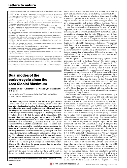
letters to nature8.Leznoff,C.C.&Lever,A.B.P.(eds)Phthalocyanines:Properties and Applications(VCH,New York,1989).9.Wang,L.S.,Ding,C.F.,Wang,X.B.&Barlow,S.E.Photodetachment photoelectron spectroscopy ofmultiply charged anions using electrospray ionization.Rev.Sci.Instrum.70,1957±1966(1999). 10.Berkowitz,J.Photoelectron spectroscopy of phthalocyanine vapors.J.Chem.Phys.70,2819±2828(1979).11.Brown,C.J.Crystal structure of b-copper phthalocyanine.J.Chem.Soc.A2488±2493(1968).12.Rosa,A.&Baerends,E.J.Metal-macrocycle interaction in phthalocyanines:density functionalcalculations of ground and excited states.Inorg.Chem.33,584±595(1994).13.PC Spartan Plus5.1(Wavefunction,Inc.,Von Carman Ave.,Irvine,California92612,USA).14.Stewart,J.J.Optimization of parameters for semiempirical methods II:put.Chem.10;221±264(1989);MOPAC:A semiempirical molecular orbital put.Aided Mol.Design4;1±105(1990).15.D'Haennens,I.J.in Encyclopedia of Physics(eds Lerner,R.G.&Trigg,G.L.)1251±1253(VCH,NewYork,1991).16.Hodgson,P.E.,Gadioli,E.&Erba,E.G.Introductory Nuclear Physics(Clarendon,Oxford,1997).17.Scheller,M.K.&Cederbaum,L.S.A construction principle for stable multiply charged molecularanions in the gas phase.Chem.Phys.Lett.216,141±146(1993).18.Weikert,H.-G.&Cederbaum,L.S.Free doubly negative tetrahalides.J.Chem.Phys.99,8877±8891(1993).19.Boldyrev,A.I.,Gutowski,M.&Simons,J.Small multiply charged anions as building blocks inchemistry.Acc.Chem.Res.29,497±502(1996).20.Vekey,K.Multiply charged ions.Mass Spectrom.Rev.14,195±225(1995).21.Brechignac,C.,Cahuzac,P.,Kebaili,N.&Leygnier,J.Temperature effects in the Coulombic®ssion ofstrontium clusters.Phys.Rev.Lett.81,4612±4615(1998).22.Schroder,D.,Harvey,J.N.&Schwarz,H.Long-lived,multiply charged diatomic TiF n+ions(n=1±3).J.Phys.Chem.A102,3639±3642(1998).Acknowledgements.We thank R.S.Disselkamp for discussions and K.Ferris for help in the theoretical calculations.This work was supported by the US Department of Energy,Of®ce of Basic Energy Sciences, Chemical Sciences Division and is conducted at the Paci®c Northwest National Laboratory,operated for the US Department of Energy by Battelle Memorial Institute.L.-S.W.is an Alfred P.Sloan research fellow.Correspondence and requests for materials should be addressed to L.-S.W.(e-mail:ls.wang@).Dual modes of thecarbon cycle since theLast Glacial MaximumH.Jesse Smith*,H.Fischer*²,M.Wahlen*,D.Mastroianni* &B.Deck**Scripps Institution of Oceanography,University of California San Diego,La Jolla,California92093-0220,USA ......................................................................................................................... The most conspicuous feature of the record of past climate contained in polar ice is the rapid warming which occurs after long intervals of gradual cooling.During the last four transitions from glacial to interglacial conditions,over which such abrupt warmings occur,ice records indicate that the CO2concentration of the atmosphere increased by roughly80to100parts per million by volume(refs1±4).But the causes of the atmospheric CO2 concentration increases are unclear.Here we present the stable-carbon-isotope composition(d13CO2)of CO2extracted from air trapped in ice at Taylor Dome,Antarctica,from the Last Glacial Maximum to the onset of Holocene times.The global carbon cycle is shown to have operated in two distinct primary modes on the timescale of thousands of years,one when climate was changing relatively slowly and another when warming was rapid,each with a characteristic average stable-carbon-isotope composition of the net CO2exchanged by the atmosphere with the land and oceans. d13CO2increased between16.5and9thousand years ago by slightly more than would be estimated to be caused by the physical effects of a58C rise in global average sea surface temperature driving a CO2ef¯ux from the ocean,but our data do not allow speci®c causes to be constrained.Carbon dioxide in the atmosphere causes a radiative forcing second only to water vapour,and so may be a central agent in climate change.Polar ice cores contain a detailed record of climate-²Present address:Alfred-Wegener-Institute for Polar and Marine Research,Columbusstrasss,D-27515 Bremerhaven,Germany.related variables which extends more than400,000years into the past4,and are especially valuable for studying variations of atmos-pheric CO2as they contain an effectively direct record,unlike atmospheric proxies such as marine carbonates or preserved organic material5which may also re¯ect biological effects.Ice cores from Antarctica,such as those of Taylor Dome and Vostok, are the best sources for palaeoatmospheric CO2measurements because they contain only small amounts of the kinds of chemical impurities,such as carbonate dust or organic acids,that may lead to contamination by in situ CO2production2,6±8.Taylor Dome ice has the additional advantage that the entire554-m-long core is from above the depth at which air trapped in bubbles in the ice forms gas±ice clathrates.This feature is important because,as we have found,the accuracy of d13CO2measurements performed on bubble-free ice may be affected by the presence of clathrates.(d13C is de®ned in Methods.)We have measured the CO2concentration and d13CO2 of air trapped in ice from Taylor Dome,Antarctica,across the last glacial termination in order to develop a time series for the carbon-isotope composition of atmospheric CO2and to constrain the mechanisms of carbon cycling between the main sources and sinks of atmospheric CO2.The atmospheric CO2concentration data3,9(Fig.1)form a record comparable to that from Byrd and Vostok1,2.The salient features include a low but variable concentration of atmospheric CO2 between27.1and18.0kyr BP(thousand years before present, where``present''is de®ned as AD1950),when it varied between 186and201parts per million by volume(p.p.m.v.);a rise,at a fairly constant rate,from190p.p.m.v.at17.0kyr BP to an early Holocene local maximum of268p.p.m.v.at10.6kyr BP,punctuated by a shallow minimum at16.1kyr BP and a drop of8p.p.m.v.between 14and13kyr BP which may be related to the Antarctic Cold Reversal3;an8p.p.m.v.decrease,from268p.p.m.v.at10.6kyr BP to260p.p.m.v.at9.1kyr BP,followed by a rise to the pre-industrial level of about280p.p.m.v.(as discussed in detail by IndermuÈhle et al.9).These data can be combined with the carbon-isotope composition of the CO2to give a better picture of how the carbon cycle operated during this time.The main features of the carbon-isotope record shown in Fig.1 include a0.5½drop in d13CO2between18.0and16.5kyr BP,and the subsequent increase of0.7½,from-7.0½to-6.3½, between16.5and9.1kyr BP,which is interrupted by two local d13CO2minima at approximately13and10kyr BP.The minimum-to-maximum d13CO2increase began1,000to2,000years after CO2began to rise,and continued to rise for,3,000years after the CO2concentration maximum at10.6kyr BP,which we interpret as a consequence of the bimodality of carbon cycling(discussed below)rather than a decoupling of CO2concentrations from carbon-isotope compositions.Furthermore,there appears to have been an extended local minimum in d13CO2between13.4and 12.3kyr BP that accompanied the Younger Dryas10but was not concurrent with the CO2concentration drop at14kyr BP.The 0.16½difference between the average d13CO2values of the Last Glacial Maximum(LGM)and Holocene(see Fig.2legend for an explanation of these groupings)is similar to the increase of 0:1960:18½estimated by Leuenberger et al.11to have occurred between the period20±40kyr BP and the early Holocene.These data show,however,that there was a signi®cant drop in d13CO2 between the end of the LGM and the beginning of the transition, and that the subsequent rise into the early Holocene was much larger than the difference between average values for the LGM and Holocene.Moreover,inferences about the carbon cycle drawn from the comparison of the LGM and Holocene averages may be misleading because there was signi®cant variability within each of those periods,and the averages depend strongly on the interval chosen to calculate them.Finally,the variability of d13CO2before17.5kyr BP and after10.3kyr BP,0.33½and 0.37½,respectively,is about half of the magnitude of theletters to natureincrease that occurs during the transition,indicating that carbon cycling also varied considerably over shorter timescales.The atmospheric portion of the carbon cycle is extremely dynamic;,20%of the CO 2in the atmosphere is exchanged with the ocean and terrestrial biosphere every year (ref.12),so the atmosphere responds very quickly to changes in CO 2cycling between these three reservoirs.The exchange of carbon can affect the isotopic composition of atmospheric CO 2for two reasons.First,the reservoirs have different carbon-isotope compositions (the d 13CO 2of the ocean is close to 0½,the terrestrial biosphere has a d 13CO 2of approximately -25½and that of pre-industrial atmos-phere was approximately -6.5½;ref.13).Second,each ¯ux of CO 2between the atmosphere and either the ocean or the terrestrial biosphere is accompanied by a different carbon-isotope fractiona-tion,resulting in isotopically unique values of d 13CO 2for each transfer.Consequently,variations in the carbon-isotope composi-tion of atmospheric CO 2can be caused by a net ¯ux of carbon between reservoirs,or by a change in the isotopic fractionation associated with a particular atmospheric ¯ux.It also follows from this that the carbon-isotope composition of the net atmospheric CO 2exchanged,d 13CO 2(ex),is a function of the relative strengths of processes which transfer CO 2into and out of the atmosphere,so different d 13CO 2(ex)values indicate different balances of processes.When a unique balance of processes persists over thousands of years,as indicated by a unique d 13CO 2(ex),we refer to it as a `mode'of the carbon cycle.In order to examine more closely the implications of the time series shown in Fig.1,it is advantageous to consider the three data groups (LGM,transition and Holocene)individually.Doing so inFig.2reveals a relationship between the concentration of atmos-pheric CO 2and its carbon-isotope composition during each of these intervals.(Figure 2is a mixing diagram,where the inverse CO 2concentration is plotted against d 13CO 2,so that addition or removal of CO 2with a given d 13C would appear as a nearly straight line with the y -intercept approximately equal to the isotopic composition of the net CO 2added to,or subtracted from,the atmosphere.)The coherent trends displayed by these groups show that the carbon cycle has operated in two distinct modes over the past 27kyr,one during the Holocene,and possibly the LGM as well,when the average d 13C of net CO 2exchanged was approximately -10½,and another during the transition,when the average d 13C of net CO 2exchanged was approximately -5½.In other words,during the period of relatively stable,slowly changing climate of the Holocene,the carbon of the net exchanged atmospheric CO 2was isotopically lighter than the average atmospheric value (that is,d d 13CO 2/dCO 2was negative).In contrast,during the period of rapidly changing climate of the transition the net exchanged CO 2was isotopically heavier (d d 13CO 2/dCO 2was positive).Therefore,these data suggest that the carbon cycle has operated in two primary modes over the past 27kyr,one when climate is changing only slowly and another when rapid warming occurs,and that although there are clearly other processes which have affected atmospheric CO 2over the past 27kyr,as is evident from the scatter in the data shown in Fig.2,those transient variations did not overwhelm the longer-term trends.Many schemes have been advanced to account for the magnitude of the rise in the concentration of atmospheric CO 2during deglaciations (see,for example,Broecker 14for a critical review),although none seem to be uniquely suf®cient.Two factors which must be included in any analysis of the glacial±interglacial increase in atmospheric CO 2content,however,are a rise in sea surface temperature (SST)and a decrease in ocean salinity (S).In the range of SST,atmospheric CO 2concentration and salinity appropriate for this study,changes in SST affect both atmospheric p CO 2and d 13CO 2,by approximately 4.2%per 8C (ref.15)and 0.11±0.13½per 8C (ref.16),respectively,while changes in salinity alter p CO 2by 10p.p.m.v.per ½S without affecting its d 13C (ref.17).Measurements per-formed on tropical corals show that SST increased by 5±68CfromFigure 1d 13CO 2and CO 2-concentration trends.The data are based on measurements of air trapped in ice from Taylor Dome,Antarctica,and are plotted against air age.Upper curve,d 13CO 2values (®lled circles)within envelopes of 1j and 2j uncertainty (indicated as dotted and solid lines,respectively;see the Methods section for details).Lower curve,CO 2concentration data shown as open circles were measured in our laboratory at SIO 3,while the solid line shown in the Holocene (for comparison)is the higher-resolution record of Indermu hle et al.9.The age axis is divided into three intervals,called ``LGM'',``transition'',and ``Holocene''on the basis of CO 2concentrations and generally accepted ages for these periods.The LGM group includes all of the points with air ages between 27.1and 18.0kyr BP ,the youngest being the last with a CO 2concentration below the highest value of the older samples.The transition group includes the points with ages between 17.0and 10.6kyr BP ,where the local CO 2maximum which we use to de®ne the start of the Holocene occurs.The Holocene group includes all the points with ages between 10.1and 1.3kyr BP (the youngest sample measured for d 13CO 2).The boundaries between the LGM and the transition,and between the transition and the Holocene,chosen here to fall at 17.5and 10.3kyr BP ,respectively,are shown as vertical dashedlines.[CO 2] (p.p.m.)1/[CO 2] (p.p.m.-1)δ13C O 2 (‰)Figure 2Mixing diagram for Taylor Dome samples:1/[CO 2]is plotted against d 13CO 2.The data are divided into three groups,as described in the ®gure:the LGM group (open triangles,6d 13CO 2points),the transition group (®lled circles,15d 13CO 2points),and the Holocene group (open squares,10d 13CO 2points).The y -intercept of the regression line through each of the three groups of data,along with the corresponding 1j uncertainty for each value,indicates the d 13C of the CO 2exchanged by the atmosphere,d 13CO 2(ex),and is shown on the ®gure.letters to naturethe last peak-glacial period to the early Holocene18,signi®cantly more than the earlier estimate of1±28C by CLIMAP19,while the change in ocean salinity,estimated from sea level change20,was approximately-1.4½.Assuming a global average D SST(sea surface temperature change)of58C,the combined effects of temperature and salinity changes should have resulted in increases in the concentration and d13CO2of roughly30p.p.m.v.and0.6½, respectively.If this were true,then all other processes which caused variations in atmospheric CO2must together have increased its concentration by,50p.p.m.v.and its d13CO2by only0.1½.A 28C global average D SST,on the other hand,would have caused no signi®cant change in the concentration of atmospheric CO2and increased d13CO2by roughly0.2½,leaving unexplained an approximately80p.p.m.concentration increase and a0.5½d13CO2increase.Adding these changes to the0.3½whole-ocean d13CO2increase which is thought to have accompanied deglaciation21,the expected increase in atmospheric d13CO2would be between0.9½and0.6½,depending on whether a D SST of5or 28C is assumed.The observed increase of0.7½would seem to imply,then,that it is not necessary to invoke a large decrease in surface ocean productivity(which would lower atmospheric d13CO2 to values more negative than are observed)to explain the d13CO2 increase during the transition.What does become necessary,then,is to explain the0.5½drop seen between18and16.5kyr BP.In the broadest sense,the atmospheric d13CO2record presented here points to the ocean as the predominant source of atmospheric CO2during the transition.This interpretation follows from two observations.First,even if a change in average global SST alone had caused the increase in d13CO2,a realistic D SST would have resulted in an increase of atmospheric CO2concentration of less than half of what is observed,so there must have been other sources of CO2 during that time.Second,because d13CO2was increasing at a rate equal to or greater than that which rising SST alone would have caused,the additional net CO2¯ux must have had a d13CO2equal to, or greater than,that of the coexisting atmosphere,eliminating the terrestrial biosphere as a possible source.The most likely explana-tion for this is an enhanced¯ux from the ocean(with a d13C close to that of the atmosphere)which transferred CO2into the atmosphere at a rate greater than the concurrent uptake of isotopically light CO2 by an expanding terrestrial biosphere.Unfortunately,the con-straints imposed by these data are insuf®cient to allow the identi-®cation of a speci®c cause for the increased¯ux of CO2from the ocean to the atmosphere.A better understanding of the carbon cycle depends not only on better models,but on additional experimental constraints on the carbon system,particularly more precise data about changes in SST,the size and composition of the terrestrial biosphere,the growth of coral reefs during periods of sea level rise, marine productivity and the chemical composition of the oceans.M ......................................................................................................................... MethodsAll samples were taken from Taylor Dome,Antarctica(7708489S,1588439E, elevation2,374m),drilled in1993/94.The methods used for determining the CO2concentration of air trapped in ice and the measurement of its carbon-isotope composition are described in detail elsewhere22,23.CO2concentration measurements have an internal precision of63p.p.m.v.(2j)and are calculated by comparison to three standards of precisely known compositions which are run with every sample.The Craig-corrected24carbon-isotope measurements, performed on our VG Prism II isotope ratio mass spectrometer,have a1j precision of60.075½,based on numerous analyses of the CO2separated from an atmospheric air standard exposed to uncrushed ice,in order to simulate the conditions of a sample run and to check for fractionation during extraction. d13CO2is reported in normal d notation as the per mil difference between the isotopic composition of the sample and standard VPDB carbon, 13C=12C sample= 13C=12C VPDB21 31;000 .The d13CO2values reported here have been corrected for the gravitational separation of gases of different masses in the®rn,and for the presence of N2O (which results in isobaric interferences with CO2during mass spectrometry).Gravitational separation in the®rn25,26was determined by using the values of d15N2of air trapped in Taylor Dome ice from Sucher27,following the approach of Sowers and Bender28.The gravitational correction for d13CO2is,0.005½per m.C-isotope data are corrected for the presence of N2O on the basis of calibrations performed in our laboratory on CO2±N2O mixtures.The N2O concentrations of atmospheric air used for this correction,adapted from Leuenberger and Siegenthaler29,are linear interpolations of the following concentrations and dates:275p.p.b.(0±9.25yr BP),200p.p.b.(16.1±27.2kyr BP).The N2O correction is,0.001½per p.p.b.of N2O.The total1j uncertainty in the reported d13CO2of a single sample,including uncertainties in the gravitational and N2O corrections,is0.085½.Duplicate analyses of samples with air ages of2.19and17.2kyr BP have a1j uncertainty of0.060½and a triplicate analysis of the sample with an air age of27.4kyr BP has a1j uncertainty of0.049½.The depth±age scale and air age±ice age differences were calculated using a combination of¯ow modelling,correlating variations in the d18O of the ice with the well-dated GISP2,and matching atmospheric CH4concentrations and d18O of O2with variations seen in GISP230.Received8October1998;accepted7June1999.1.Barnola,J.M.,Raynaud,D.,Korotkevich,Y.S.&Lorius,C.Vostok ice core provides160,000-yearrecord of atmospheric CO2.Nature329,408±414(1987).2.Neftel,A.,Oeschger,H.,Staffelbach,T.&Stauffer,B.CO2record in the Byrd ice core50,000±5,000years BP.Nature331,609±611(1988).3.Fischer,H.,Wahlen,M.,Smith,H.J.,Mastroianni,D.&Deck,B.Ice core records of atmospheric CO2around the last three glacial terminations.Science283,1712±1714(1999).4.Petit,J.R.et al.Climate and atmospheric history of the past420,000years from the Vostok ice core,Antarctica.Nature399,429±436(1999).5.Marino,B.,McElroy,M.B.,Salawitch,R.J.&Spaulding,W.G.Glacial-to-interglacial variations in thecarbon isotopic composition of atmospheric CO2.Nature357,461±466(1992).6.Anklin,M.,Barnola,J.-M.,Schwander,J.,Stauffer,B.&Raynaud,D.Processes affecting the CO2concentrations measured in Greenland ice.Tellus B47,461±470(1995).7.Delmas,R.J.A natural artefact in Greenland ice core CO2measurements.Tellus B45,391±396(1993).8.Barnola,J.M.et al.CO2evolution during the last millennium as recorded by Antarctic and Greenlandice.Tellus B47,264±272(1995).9.IndermuÈhle,A.et al.Holocene carbon-cycle dynamics based on CO2trapped in ice at Taylor Dome,Antarctica.Nature398,121±126(1999).10.Fairbanks,R.G.The age and origin of the``Younger Dryas Climate Event''in Greenland ice cores.Paleoceanography5,937±948(1990).11.Leuenberger,M.,Siegenthaler,U.&Langway,C.C.Carbon isotope composition of atmospheric CO2during the last ice age from an Antarctic ice core.Nature357,488±490(1992).12.Tans,P.P.,Berry,J.A.&Keeling,R.F.Oceanic13C/12C observations:a new window on ocean CO2uptake.Glob.Biogeochem.Cycles7,353±368(1993).13.Friedli,H.,Lotscher,H.,Oeschger,H.,Siegenthaler,U.&Stauffer,B.Ice core record of the13C/12C ofatmospheric CO2in the past two centuries.Nature324,237±238(1986).14.Broecker,W.S.&Henderson,G.M.The sequence of events surrounding T ermination II and theirimplications for the cause of glacial-interglacial CO2changes.Paleoceanography13,352±364(1998).15.Takahashi,T.,Olafsson,J.,Goddard,J.G.,Chipman,D.W.&Sutherland,S.C.Seasonal variation ofCO2and nutrients in the high-latitude surface oceans:a comparative study.Glob.Biogeochem.Cycles 7,843±878(1993).16.Mook,W.G.,Bommerson,J.C.&Staverman,W.H.Carbon isotope fractionation between dissolvedbicarbonate and gaseous carbon dioxide.Earth Planet.Sci.Lett.22,169±176(1974).17.Weiss,R.F.Carbon dioxide in water and seawater:the solubility of a non-ideal gas.Mar.Chem.2,203±215(1974).18.Guilderson,T.P.,Fairbanks,R.G.&Rubenstone,J.L.Tropical temperature variations since20,000years ago:modulating interhemispheric climate change.Science263,663±665(1994).19.CLIMAP Project Members Seasonal Reconstructions of the Earth's Surface at the Last Glacial Maximum(Map and Chart Ser.,MC-36,Geol.Soc.Am.,Boulder,1981).20.Fairbanks,R.G.A17,000-year glacio-eustatic sea level recordÐin¯uence of glacial melting rates onthe Younger Dryas Event and deep-ocean circulation.Nature342,637±642(1989).21.Duplessy,J.C.et al.Deepwater source variations during the last climatic cycle and their impact on theglobal deepwater circulation.Paleoceanography3,343±360(1988).22.Wahlen,M.,Allen,D.&Deck,B.Initial measurements of CO2concentrations(1530to1940AD)in airoccluded in the GISP2ice core from central Greenland.Geophys.Res.Lett.18,1457±1460(1991).23.Smith,H.J.,Wahlen,M.,Mastroianni,D.&Taylor,K.C.The CO2concentration of air trapped inGISP2ice from the LGM-Holocene transition.Geophys.Res.Lett.24,1±4(1997).24.Craig,H.Isotopic standards for carbon and oxygen and correction factors for mass-spectrometricanalysis of carbon dioxide.Geochim.Cosmochim.Acta12,133±149(1957).25.Craig,H.,Horibe,Y.&Sowers,T.Gravitational separation of gases and isotopes in polar ice caps.Science242,1675±1678(1988).26.Schwander,J.The Environmental Record in Glaciers and Ice Sheets(eds Oeschger,H.and Langway,C.C.)53±67(Wiley and Sons,New York,1989).27.Sucher,C.Trapped Gases in the Taylor Dome Ice Core:Implications for East Antarctic Climate Change.Thesis,Univ.Rhode Island(1997).28.Sowers,T.&Bender,M.Elemental and isotopic composition of occluded O2and N2in polar ice.J.Geophys.Res.94,5137±5150(1989).29.Leuenberger,M.&Siegenthaler,U.Ice-age atmospheric concentration of nitrous oxide from anAntarctic ice core.Nature360,449±451(1988).30.Steig,E.J.et al.Synchronous climate changes in Antarctica and the North Atlantic.Science282,92±95(1998).Acknowledgements.We thank G.Hargreaves and J.Fitzpatrick for help obtaining samples,and E.Steig and E.Brook for sharing their depth-age scales.This work was supported by the NSF and the Director's of®ce at the Scripps Institution of Oceanography.Correspondence and requests for materials should be addressed to H.J.S.(e-mail:hjsmith@).。
天文算法译著—许剑伟和他的译友第 1章注释与提示第 2章关于精度第 3章插值第 4章曲线拟合第 5章迭代第 6章排序第 7章儒略日第 8章复活节日期第 9章力学时和世界时第10章地球形状第11章恒星时与格林尼治时间第12章坐标变换第13章视差角第14章升、中天、降第15章大气折射第16章角度差第17章行星会合第18章在一条直线上的天体第19章包含三个天体的最小圆第20章岁差第21章章动及黄赤交角第22章恒星视差第23章轨道要素在不同坐标中的转换第24章太阳位置计算第25章太阳的直角坐标第26章分点和至点第27章时差第28章日面计算第29章开普勒方程第30章行星轨道要素第31章行星位置第32章椭圆运动第33章抛物线运动第34章准抛物线第35章一些行星现象的计算第36章冥王星第37章行星的近点和远点第38章经过交点第39章视差修正第40章行星圆面被照亮的比例及星等第41章火星物理表面星历计算(未译) 第42章木星物理表面星历计算(未译) 第43章木星的卫星位置(未译)第44章土星环(未译)第45章月球位置第46章月面的亮区第47章月相第48章月亮的近地点的远地点第49章月亮的升降交点第50章月亮的最大赤纬第51章月面计算第52章日月食第53章日月行星的视半径第54章恒星的星等第55章双星第56章日晷的计算备注译者说明原著《天文算法》天文算法天文算法 (1)前言 (1)第一章注释与提示 (1)第二章关于精度 (7)第三章插值 (16)第四章曲线拟合 (29)第五章迭代 (40)第六章排序 (47)第七章儒略日 (51)第八章复活节日期 (58)第九章力学时和世界时 (61)第十章地球形状 (65)第十一章恒星时与格林尼治时间 (70)第十二章坐标变换 (75)第十三章视差角 (80)第十四章天体的升、中天、降 (83)第十五章大气折射 (87)第十六章角度差 (89)第十七章行星会合 (97)第十八章在一条直线上的天体 (99)第十九章包含三个天体的最小圆 (101)第二十章岁差 (104)第二十一章章动及黄赤交角 (112)第二十二章恒星视差 (116)第二十三章轨道要素在不同坐标中的转换 (125)第二十四章太阳位置计算 (129)第二十五章太阳的直角坐标 (137)第二十六章分点和至点 (143)第二十七章时差 (148)第二十八章日面计算 (153)第二十九章开普勒方程 (157)第三十章行星的轨道要素 (172)第三十一章行星位置 (175)第三十二章椭圆运动 (178)第三十三章抛物线运动 (193)第三十四章准抛物线 (197)第三十五章一些行星现象的计算 (201)第三十六章冥王星 (211)第三十七章行星的近点和远点 (215)第三十八章经过交点 (221)第三十九章视差修正 (224)第四十章行星圆面被照亮的比例及星等 (230)第四十一章火星物理表面星历计算(未译) (234)第四十二章木星物理表面星历计算(未译) (234)第四十三章木星的卫星位置(未译) (234)第四十四章土星环(未译) (234)第四十五章月球位置 (235)第四十六章月面被照亮部分 (243)第四十七章月相 (246)第四十八章月亮的近地点和远地点 (252)第四十九章月亮的升降交点 (259)第五十章月亮的最大赤纬 (261)第五十一章月面计算 (265)第五十二章日月食 (273)第五十三章日月行星的视半径 (284)第五十四章恒星的星等 (286)第五十五章双星 (289)后记 (1)前言十分诚恳地感谢许剑伟和他的译友!在此我作一个拱手。

火星救援阿西达利亚平原好了队友们互相看着点儿All right, team, stay in sight of each other.NASA 战神三号♥ 降落地点今天让NASA以我们为傲吧Let's make NASA proud today.任务日:第18个火星日那边情况如何沃特尼How's it looking over there, Watney?你会很高兴知道坐标方格14-28区里Well, you'll be happy to hear that in grid section 14-28,颗粒大部分都比较粗糙the particles were predominantly coarse...但29区的就精细多了but in 29, they're much finer...用它们做化学分♥析♥应该很理想And they should be ideal for chem analysis.大家听到了吗Did everybody hear that?马克刚刚发现了泥土Mark just discovered dirt.我们要通知媒体吗Should we alert the media?抱歉你今天要干什么来着马丁内兹Sorry, what are you doing today, Martinez?确保飞行器还立着吗Making sure the MAV is still upright?要知道目视检查仪器I'd like you to know that visual inspection of the equipment...也是任务成功必不可少的一步is imperative to mission success.同时我还想报告飞行器的确好好立着呢I also would like to report that the MAV is still upright.沃特尼你一直开着通话频道Watney, you keep leaving your channel open,马丁内兹就会回应你which leads to Martinez responding...我们所有人就会听到which leads to all of us listening...然后我就会很烦which leads to me being annoyed.收到了马丁内兹队长想请你Roger that. Martinez, the captain would like you to please...闭上你那张利嘴shut your smart mouth.能用别的词来形容马丁内兹的嘴巴吗We'd prefer to use a different adjective to describe Martinez's mouth.贝克刚刚是不是侮辱了我Did Beck just insult me?是"贝克博士" 没错"Dr. Beck." And yes.我很乐意从这里把无线电关掉指挥官Happy to turn the radios off from here, Commander.您下令就行Just say the word.等等约翰逊Wait, Johanssen.一直保持通话是...Constant communication is the hallmark...关了Shut 'em off.不要No.不啊拜托No. Excuse me.我为我的同胞向你道个歉沃格尔I apologize for my countrymen, Vogel.道歉接受Accepted.还需要多少样本指挥官How many samples do we need, Commander?七个Seven.每个100克100 grams each.紧急情况任务状态更新有个任务状态更新We have a mission update.风暴警告A storm warning.指挥官你该进来Commander, you should come inside.你会想看看这个You're gonna want to see this.看什么What is it?A storm warning.我在今早的简报上看到了I saw that in this morning's briefing.我们会在风暴到达前回来We'll be inside before it hits.是啊但他们升级了预测Yeah, they upgraded their estimate.风暴会猛烈得多The storm's gonna be a lot worse.马丁内兹情况看上去如何Martinez, how does it look?不太妙Not good.直径1200千米角度24.41度"1,200 kilometers in diameter, bearing 24.41 degrees."那是径直冲我们来了That's tracking right towards us.根据目前的增强趋势"Based on current escalation,预计将有8600牛顿的力"estimated force of 8,600 Newtons."任务中止力是多少What's the abort force?7500牛顿7,500.超过那个飞行器就可能倾倒Anything more than that and the MAV could tip.我们要中止吗Do we scrub?启动中止程序Begin abort procedure.我们的预测是会有误差We are estimating with a margin of error.也许等一会就没事了We could wait it out.我们等等吧Let's wait it out.我们等等吧Let's wait it out.指挥官Commander?准备紧急起飞Prep emergency departure.Commander?我们得中止那是命令We're scrubbed. That's an order.马丁内兹还要多久能起飞Martinez, how long before take-off?12分钟12 minutes.任务日任务日能见度基本为零Visibility is almost zero.要是谁走丢了跟着我的宇航服遥感信♥号♥♥ Anyone gets lost, hone in on my suit's telemetry.气闸室减压中-准备好了吗-好了- You ready? - Ready.指挥官您没事吧Commander, are you okay?没事I'm okay.任务日任务日指挥官我们倾斜了10度Commander, we're at 10 degrees,超过12.3度飞行器就会倾倒and the MAV is gonna tip at 12.3.我们也许能阻止飞行器倾倒We might be able to keep the MAV from tipping.怎么办How?把通讯杆的电缆作为牵引绳Use the cables from the comms mast as guy-lines...用探测车拉着它anchor it with the rover's.小心Watch out!任务日沃特尼Watney!任务日警告检测到宇航服破损Warning. Suit breach detected.失去信♥号♥♥What happened?他被击中了He was hit.沃特尼回复Watney, report.在我们失联前Before we lost telemetry,他的减压警报响了his decompression alarm went off.约翰逊你最后一次看到他是在哪里Johanssen, where did you last see him?我不知道他在哪里I don't know where he is.沃特尼失去信♥号♥♥他宇航服上显示的生命体征如何What are the vitals on his suit?-他掉线了-什么都没有- He's offline. He's offline. - Negative.完全失去了沃特尼的信♥号♥♥A complete loss of signal on Watney.-贝克-怎么了- Beck! - Yeah.在减压的情况下他能活多久How long can he survive decompression?不足一分钟Less than a minute.排成一线向西走Line up, walk west.他也许倒在地上了可别踩着他He may be prone. We don't wanna step over him.指挥官...Commander...-10.5度了-警告过度倾斜- we're at 10.5 degrees. - Warning. Excessive tilt.再刮一阵就要到11度了Tilting to 11 with all the gusts of wind.收到Copy that.大家跟紧马丁内兹宇航服的遥感信♥号♥♥ Everyone, hone in on Martinez's suit.它会带领你们到气闸室It'll get you to airlock.进去去准备发射Get in, prep for launch.你呢指挥官What about you, Commander?我再找下他你们快走I'm gonna search a little longer. Get moving!快Go!沃特尼Watney!沃特尼回复Watney, report!飞行器已经倾斜到11.6度了The MAV's at 11.6 degrees.再刮一阵风我们就要翻了One good gust and we're tipping.假如要翻了你就发射If it tips, you launch.你真的觉得我会把你抛下吗You really think I'm gonna leave you behind?那是命令马丁内兹That's an order, Martinez.马克Mark!马克能听见我说话吗Mark! Can you hear me?马丁内兹近程雷达呢Martinez, what about the proximity radar?那东西能检测到沃特尼的宇航服吗Could that detect Watney's suit?那是用来从轨道上观测赫耳墨斯的It's made to see the Hermes from orbit...而不是观测一件宇航服上的一小块金属not a little piece of metal from a single suit.-试试吧-收到- Give it a try. - Roger.她想什么呢What is she thinking?她清楚红外线穿不过沙暴的She knows the infrared can't get through a sandstorm.她是死马当活马医了She's grasping for anything.近程雷达什么也没有检测到We've got negative contact on the proximity radar.什么都没有吗Nothing?是的我连居住舱都看不太清了No. I can barely see the HAB.指挥官我知道你不想听但是Commander, I know you don't wanna hear this, but...马克死了Mark is dead.指挥官Commander!你♥他♥妈♥怎么回事啊Hey, what the hell is wrong with you, man?我朋友刚刚死了My friend just died.我不希望我的指挥官也死了I don't want my commander to die, too.稳度警告Stability warning.我们要倾倒了We're tipping!指挥官你得回到飞船上马上Commander, you need to get back to the ship, now! 13度了13 degrees.要是失去了平衡就再也立不起来了If we pass balance, we'll never rock back.我还剩最后一招I've got one more trick left,然后我就要执行命令了指挥官and then I'm following orders, Commander.你启动了轨道机动系统吗You're firing the OMS?没错That's right.指挥官Commander!来了On my way.约翰逊走吧Johanssen, let's go.马克Mark!现在勉强维持在11.5度We're at 11.5 and holding.下令就可以出发了Ready to go on your command.准备发射Ready to launch.指挥官Commander.你得告诉我能不能起飞I need you to verbally tell me whether or not to.发射Launch.在中♥央♥标准时间凌晨4:30左右At around 4:30 A.M. central standard time...我们的卫星检测到了一场风暴our satellites detected a storm正在接近战神三号♥火星任务站approaching the Ares 3 mission site on Mars.6:45 风暴升级为强烈风暴6:45, the storm had escalated to severe...我们别无选择只能中止任务and we had no choice but to abort the mission.多亏露易丝指挥官的快速反应...Thanks to the quick action of Commander Lewis...战神三号♥宇航员正在返程宇航员贝克约翰逊astronauts Beck, Johanssen,马丁内兹以及沃格尔Martinez and Vogel...都成功登上了火星上升飞行器were all able to reach the Mars ascent vehicle...并于中♥央♥时间7:28启动了紧急发射and perform an emergency launch at 7:28 central time.不幸的是在撤离过程中...Unfortunately, during the evacuation...宇航员马克·沃特尼被飞石击中身亡astronaut Mark Watney was struck by debris and killed.指挥官露易丝以及剩余队员Commander Lewis and the rest of her team...则成功与赫耳墨斯对接were able to intercept safely with the Hermes如今正在返程回家and are now heading home.但马克·沃特尼牺牲了But Mark Watney is dead.桑德斯局长Director Sanders!氧气含量临界Oxygen level critical.氧气含量临界Oxygen level critical.氧气含量...Oxygen level...压力稳定Pressure stable.局部麻醉缝合操Fuck.好吧Okay.任务日第19个火星日居住舱铺位好吧Okay.你好这里是马克·沃特尼宇航员Hello, this is Mark Watney, astronaut.我拍摄这段日志是为了记录...I'm entering this log for the record...第19个火星日居住舱铺位以防我死了In case I don't make it.现在是第19个火星日的6点53分It is 06:53 on sol 19...而我还活着and I'm alive.显而易见的Obviously.但我猜对于我的队友和NASA而言But I'm guessing that's gonna come as a surprise 这将会是个惊喜to my crewmates and to NASA.第19个火星日居住舱铺位对全世界而言也是真的所以And to the entire world, really, so...惊喜吧Surprise.我没有死在第18个火星日I did not die on sol 18.我的猜想是...Best I can figure...这一截通讯天线断了this length of our primary communications antenna broke off...刺穿了我的生命监控器and tore through my bio-monitor...在我身上也开了个口子and ripped a hole in me as well.但其实那截天线和血But the antenna and the blood, really,封住了我宇航服上的裂缝managed to seal the breach in my suit...救了我一命which kept me alive,即便队友们一定都以为我死了even though the crew must have thought I was dead.我没有办法联♥系♥上NASAI have no way to contact NASA.而且就算是联♥系♥上了也得等上四年And even if I could, it's gonna be four years...才有载人任务能到我身边until a manned mission can reach me.我在这个设计上只能撑31天的居住舱里And I'm in a HAB designed to last 31 days.如果氧合器坏了我会窒息而死If the oxygenator breaks, I'm gonna suffocate.如果净水回收机坏了我会渴死If the water reclaimer breaks, I'll die of thirst.假如居住舱破损了我就会If the HAB breaches, I'm just gonna, kind of...内爆而死implode.假如奇迹出现上述情况都没有发生And if by some miracle, none of that happens...我最终还是会耗尽食物eventually I'm gonna run out of food.所以So...没错Yeah.好吧Yeah.约翰逊我不会死在这里I'm not gonna die here.第21个火星日任务日32...32...33...34, 35, 36.糖醋鸡Sweet and sour chicken.真空冲水感恩节之前不要打开看看有什么What do we got?任务日好了来算算吧Right, let's do the math.我们的地表任务本应是31个火星日Our surface mission here was supposed to last 31 sols.为了以防万一他们送了68个火星日的食物For redundancy, they sent 68 sols worth of food.还是6人的量That's for 6 people.我一人吃的话可以撑300个火星日So for just me, that's gonna last 300 sols...控制饮食估计能撑400个火星日which I figure I can stretch to 400 if I ration.所以我得想个办法种出够吃3年的食物So I got to figure out a way to grow three years' worth of food here.在这片不毛之地上On a planet where nothing grows.幸运的是Luckily...战神生物探索火星上的进程我是个植物学家I'm a botanist.火星将会畏惧我的植物学之力Mars will come to fear my botany powers.有机废料生物危害人类排泄物M 沃特尼任务日任务日任务日压力稳定Pressure stable.任务日订书针出来了Staple came out.第24个火星日葡萄汁去你的火星Fuck you, Mars.第31个火星日任务日约翰逊天呐Johanssen, Jesus.第36个火星日问题是水The problem is water.我铺设了126平方米的土地I have created 126 square meters of soil.但每立方米的土壤需要40升的水But every cubic meter of soil requires 40 liters of water才能耕种to be farmable.所以我得搞出来更多水So I gotta make a lot more water.好消息是我知道如何做Good thing is, I know the recipe.用氢气加上氧气再点燃You take hydrogen, you add oxygen, you burn.现在飞行器中有好几百升没用过的联氨Now, I have hundreds of liters of unused hydrazine at the MDV.假如我用铱催化剂分解联氨If I run the hydrazine over an iridium catalyst,它将分解成氮气和氢气it'll separate into N2 and H2.然后假如我直接将氢气导入一个小空间And then if I just direct the hydrogen into a small area...然后点燃它and burn it.幸运的是在人类历史上...Luckily, in the history of humanity...从没因为点燃氢气而出过什么事nothing bad has ever happened from lighting hydrogen on fire. NASA讨厌明火NASA hates fire.就因为"火会让大家死在太空"这套说辞Because of the whole "fire makes everybody die in space" thing.所以这里的所有用品都是阻燃的So, everything they sent us up here with is flame-retardant...除了一个显著的例外...with the notable exception of...马丁内兹的私人物品Martinez's personal items.抱歉了马丁内兹I am sorry, Martinez.但假如你不希望我翻你的东西的话...But if you didn't want me to go through your stuff...你就不应该把我留在这个荒芜的星球等死you shouldn't have left me for dead on a desolate planet.再说了基于我这个现状By the way, I'm figuring you're gonna be fine with this,我想你会理解的given my present situation.就靠你了Counting on you.所以没错我把自己炸飞了So, yeah, I blew myself up.我的猜想是Best guess...我计算的时候I forgot to account for忘了把我呼出的氧气算进去了the excess oxygen that I've been exhaling when I did my calculations.因为我是个白♥痴♥Because I'm stupid.好了我要回去干活儿了Yeah, I'm gonna get back to work here...等我耳鸣一停止我就开工Just as soon as my ears stop ringing.趣味附注Interesting side note,喷气推进实验室就是这么建立的this is actually how the Jet Propulsion Lab was founded.加州理工的五个学生试图制♥造♥火箭燃料Five guys at Caltech were trying to make rocket fuel...差点没把宿舍烧了and they nearly burned down their dorm.但他们没有被开除And rather than expel them...而是被赶去了附近的农场they banished them to a nearby farm,说让他们继续研究told them to keep working.因此我们就有了太空项目And now we have a space program.好了Okay.任务日任务日任务日第48个火星日第54个火星日你好呀Hey, there.国家很荣幸有马克为我们的太空项目效力The nation was blessed to have Mark serving in our space program.我们因失去他而深感悲痛While his loss will be deeply felt...NASA的全体成员将会勇往直前The men and women of NASA will soldier forth...肩负组织的使命不断前进提升Onward and upward in the mission of their agency.泰迪·桑德斯NASA局长由此他们将不辱马克的遗志By doing so, they honor the legacy Mark's leaving behind...也将确保他死得其所and they ensure his sacrifice will not be in vain.约翰森航♥天♥中心休斯顿得克萨斯州文森特·卡普尔火星任务主管NASA我有幸在此发言I have the honor of speaking不仅代表NASA的全体成员not only for the men and women of NASA...也代表了世界人♥民♥but for people all over the world...我觉得你的演讲不错I thought you gave a lovely speech, by the way.我需要你授权我的卫星观测I need you to authorize my satellite time.不可能It's not gonna happen.我们有五次战神任务的经费We're funded for five Ares missions.我觉得我能说服国会资助第六次I think I can get Congress to authorize a sixth.-不行-战神三号♥在第18个火星日就撤离了- No. - Ares 3 evac'd after 18 sols.还有价值半次任务的物资在上面There's half a mission worth of supplies up there.我可以将其按正常任务的小部分价格低价卖♥♥出I can sell it at a fraction of of the cost of a normal mission...我只想知道我们还剩什么And all I have to know is what's left of our assets.不是只有你想用卫星观测You're not the only one who needs satellite time.我们马上就要进行战神四号♥的补给任务We've got the Ares 4 supply missions coming up.现在更应关注夏帕瑞丽陨石坑We should be focusing on the Schiaparelli crater.可我们有12颗卫星呢Okay, we got 12 satellites up there.就抽空看一下Surely we can spare a few hours...这不是卫星观测的问题文斯It's not about the satellite time, Vince.我们是受到广大公众关注的We're a public domain organization.这种事必须公开透明We need to be transparent on this.没错Okay.只要我们把卫星对准那里The second we point the satellites at the hab...就是向全世界直播马克·沃特尼的尸体I broadcast pictures of Mark Watney's dead body to the world.你是担心出现公♥关♥危机You're afraid of a PR problem?当然害怕了Of course I'm afraid of a PR problem.还想通过新任务Another mission?要是一个死去的宇航员Congress won't reimburse us for a paper clip...上了《华♥盛♥顿♥邮♥报♥》的头版头条If I put a dead astronaut on the front page国会一个子儿都不会拨给我们了of the Washington post.他会一直在的泰迪他He's not going anywhere, Teddy. I mean, he's not...他不会腐烂你又不是不知道He's not gonna decompose, you know.他会一直留在那儿He's gonna be up there forever.气象学预计他的尸体正常气象运动下Meteorology estimates that he'll be covered in sand...一年内就会被黄沙掩埋From normal weather activity within a year.总不能等一年吧我们还有工作We can't wait a year. We got work to do.战神五号♥五年内都不可能发射Ares 5 won't even launch for five years.时间多着呢We have plenty of time.好吧Okay.好Okay.好你听我说Okay, consider this.现在全世界都是站在我们这边的Right now, the world's on our side.人们同情沃特尼一家人Sympathy for the Watney family.战神六号♥能把他的尸体带回来Ares 6 could bring his body home.并不是说这是战神六号♥的唯一目的Now, we don't say that's the purpose of the mission...但至少应该是其中的一部分But we make it clear that that would be a part of it.就这么定了We frame it that way.可以得到国会的支持但不能再等一年More support from congress. But not if we wait a year.如果再等一年谁都不在乎了We wait a year, nobody gives a shit.NASA 控制中心德克萨斯州休斯敦约翰森航♥天♥中心凌晨1:30明迪·帕克NASA 卫星联络部收到新信息文森特·卡普尔Vincent Kapoor?你好明迪查看以下坐标纬度: 46°42′0″经度: 22°0′0″(46.7°, -22°)文森特6-26-2.7-6-27-6-2.阿西达里亚平原Acidalia planitia.第54个火星日第18个火星日第18个火星日第54个火星日怎么回事What?第54个火星日第18个火星日第54个火星日第18个火星日第54个火星日第54个火星日第18个火星日第54个火星日你好警卫室吗Hi. Security?我是卫星监控室的明迪·帕克This is Mindy Park in Satcon.我需要紧急联络文森特·卡普尔I need the emergency contact for Vincent Kapoor.没错就是他Yes, him.对事情紧急Yes, it's an emergency!凌晨2:30有多大的可能性How sure?100%100%.安妮·蒙特罗斯信息部负责人这是在逗我吗You've got to be shitting me.证明一下你的说法Prove it to me.首先For a start...太阳能发电板被清理了The solar panels have been cleaned.有可能是风吹干净的They could have been cleaned by wind.后退一点看漫游者2号♥Back it up. Look at Rover 2.根据宇航日志According to the logs,第17个火星日指挥官露易丝把它拿出来commander Lewis took it out on sol 17...插到居住舱充电Plugged it into the hab to recharge.但是它的位置变了It's been moved.有可能她挪走了但忘了记录She could have forgotten to log the move.不不太可能No, not likely.为什么不问问露易丝Why don't we just ask Lewis?让地面通讯直接问她Let's get on capcom and ask her directly right now.不不如果沃特尼真的还活着No. No. If watney is really alive,我们不能让战神三号♥的队员知道we don't want the Ares 3 crew to know.怎么能不告诉他们How can you not tell them?他们再有十个月就能回来了They have another 10 months on their trip home.太空旅行很危险Space travel is dangerous.他们必须得集中精力不能分神They need to be alert and undistracted.但他们都以为他死了But they already think he's dead.如果发现他被活着抛弃在那儿And they'd be devastated to find out他们会更痛苦they left him there alive.可是你们都没有想清楚I'm sorry, but you have not thought this through I mean.我们怎么说啊"亲爱的美国民众What are we gonna say? "Dear America...还记得我们之前那位牺牲了Remember that astronaut we killed还举办了盛大葬礼的宇航员吗And had a really nice funeral for?他没死我们把他落在火星上了抱歉Turns out he's alive and we left him on Mars. Our bad.真诚的NASA""Sincerely, NASA."你们意识到我们会受到多少唾骂吗Do you realize the shitstorm that is about to hit us?我们怎么应对民众How are we going to handle the public?按规定24小时之后必须公布这些画面Legally, we have 24 hours to release these pictures.我们要随之发布一份声明We release a statement with them.不能让人们自己瞎琢磨We don't want people working it out on their own.是长官Yes, sir.但如果我没算错我们派遣救援之前But if my math is right, he's going to starve to death他就饿死了long before we can help him.你能想象他都经历了什么吗Can you imagine what he's going through up there?他离家五千万英里He's 50 million miles away from home.他独自一人He thinks he's totally alone.觉得已经被我们抛弃He thinks we gave up on him.这会对一个人的心理产生多大的影响What does that do to a man, psychologically?他现在到底在想什么What the hell is he thinking right now?任务日再让我听这么难听的迪斯科I'm definitely gonna die up here...我肯定会死在这里If I have to listen to any more god-awful disco music.天哪露易丝指挥官My god, commander Lewis,你就没有点能跟上时代潮流的东西吗couldn't you have packed anything from this century?♪Turn the beat around♪不我可不打算"舞力无限"No, I am not gonna "Turn the beat around."我拒绝I refuse to.桑德斯先生桑德斯先生Mr. Sanders? Mr. Sanders?为了和马克·沃特尼取得联♥系♥ What attempts have been made你们都做了什么呢to make contact with Mark Watney?我们仍在努力We're working on it.他的补给能维持生存吗Does he have enough supplies to survive?我们会研究的We'll be looking into that.官方有什么说法呢What does this say about the agency?您会辞职吗Are you gonna resign?不会No.桑德斯局长Director Sanders!第70个火星日该考虑得长远些了It's time to start thinking long term.NASA的下一个任务是战神四号♥The next NASA mission is Ares 4...它的预计着陆点在夏帕瑞丽陨石坑And it's supposed to land at Schiaparelli crater...距离这里3200公里3200 kilometers away.3200公里3,200 kilometers.四年后下一个航♥天♥小组到达的时候In four years, when the next Ares crew arrives,我必须到达着陆点I'll have to be there.也就意味着我得去陨石坑等待Which means I have to get to the crater.那么问题来了Okay, so here's the rub.我只有一辆探测车I've got one working rover最远行驶距离35公里designed to go a Max distance of 35 kilometers...之后就必须回到居住舱给电池充电Before the battery has to be recharged at the hab.这是第一个问题That's problem A.第二个问题就是这么远距离的行进Problem B is this journey's gonna take me我需要大约50天才能完成roughly 50 days to complete.所以我必须拖着So I gotta live for 50 days...一整车的补给在探测车里inside a rover with marginal life support生存至少50天the size of a small Van.所以面临着这么多问题So, in the face of overwhelming odds,任务日我只有一个选择I'm left with only one option.我得大展科学神威了I'm gonna have to science the shit out of this.任务日任务日好成功了Okay, so, success.我借助一号♥探测车将电池寿命延长了一倍I have doubled my battery life by scavenging Rover 1.但如果我开了暖气But if I use the heater...每天暖气就要消耗一半的电池I will burn through half my battery every day.如果不用暖气我就会If I do not use my heater, I will be...因为热量不足被慢慢冻死slowly killed by the laws of thermodynamics.我很想立即就解决这个问题I would love to solve this problem right now可不幸的是but unfortunately...任务日我的蛋蛋都快冻掉了My balls are frozen.不行我认输我认输I can't. I'm calling it. I'm calling it.任务日好消息我可能有办法Good news, I may have a solution解决供暖问题了to my heating problem.坏消息就是我得把Bad news, it involves me digging up放射性同位素热电机挖出来the radioisotope thermoelectric generator.如果我的记得没错的话Now, if I remember my training correctly,航♥空♥训练有一课叫做one of the lessons was titled..."千万别把放射性物质挖出来马克""Don't dig up the big box of plutonium, Mark."放射性同位素热电机对航♥天♥器是好东西I get it. RTGs are good for spacecraft,但要是泄漏了but if they rupture around humans...附近的人类就连渣都不剩no more humans.所以一着陆我们就把它埋了起来Which is why we buried it when we arrived.插上这面旗And planted that flag...也就没有人会笨到So we would never be stupid enough去靠近它to accidentally go near it again.但只要我没把它弄坏就行But as long as I don't break it...我刚刚差点就大声喊出I almost just said一切都会好起来的"Everything will be fine" out loud.重点是我现在一点都不冷了Look, the point is, I'm not cold anymore.当然了我也可以想到我之所以不冷了And sure, I could choose to think about the fact that I'm warm...是因为我正在受到后面放射性同位素热电机的辐射Because I have a decaying radioactive isotope riding right behind me...现在我还有更大的问题But right now, I got bigger problems on my hands.任务日我翻遍了露易丝指挥官I have scoured every single data file硬盘上所有的文件夹on commander Lewis' personal drive.这绝对是最不像迪斯科的歌♥This is officially the least disco song she owns.♪Lookin' for some hot stuff baby this evenin'♪♪I need some hot stuff baby tonight♪♪I want some hot stuff baby this evenin'♪♪Gotta have some hot stuff♪♪Gotta have some lovin' tonight♪♪I need hot stuff♪♪I want some hot stuff♪♪I need hot stuff♪-这位-沃特尼这是要去哪里- Yeah. - Where is Watney going?我们认为他是准备长途旅行We believe that he's preparing for a journey.他一直在进行增量测试He's been conducting incremental tests...每次驾驶二号♥探测车Taking the Rover 2 out for longer走得一次比一次远and longer trips each time.要去哪里他为什么要离开相对安全的居住舱呢To what end? Why would he leave the relative safety of the hab?我们认为他计划到Well, we think that he plans to travel战神四号♥的着陆点to the Ares 4 launch site...以便和我们取得联♥系♥In order to make contact with us,但这是一次很危险的赌博but it would be a dangerous gamble.但如果我们能和他取得联♥系♥But if we could talk to him,我们会告诉他原地不动we would tell him to stay put...相信我们一定会竭尽全力And to trust that we are doing everything in our power把他活着带回家to bring him home alive.非常感谢Thank you very much.别说"活着带回来"这种话文森特Don't say "Bring him home alive," Vincent.你又不是不知道这种记者会太难了You know what? These interviews aren't easy.原谅我想说点积极向上的话So god forbid I try to say something proactive and positive.安妮Annie.再也不让文森特上电视遵命No more Vincent on TV. Copy that.76公里我看的没错吧76 kilometers. Am I reading that right?在问我吗Are you asking me?是啊I am.是的长官Yes, sir.马克从居住舱出发开了两小时Mark drove two hours straightaway from the hab...进行了短期的舱外活动后又开了两小时Did a short EVA and then drove for another two.我们认为短暂的舱外活动是为了换电池We think the EVA was to change batteries.他没有装氧合器He didn't load up the oxygenator和净水回收机吗or the water reclaimer?每行驶41小时都会有17分钟的空白。
较亮的星云摘自洪韵芳主编的《天文爱好者手册》说明:(1)本表所列天体系在我国各地可见到的较亮的星云。
(2)“望远镜口径”系指用所列口径的望远镜能较清晰地看到所述天体。
(3)附注栏所述供业余爱好者参考。
主要亮星排行表NO 名称英文星名所属星座视星等距离(光年)太阳Sun -26.721 天狼星 Sirius 大犬座-1.46 8.62 老人星 Canopus 船底座-0.72 803 南门二 Rigel Kentaurus 半人马座-0.30 4.34 大角星 Arcturus 牧夫座-0.04 305 织女星 Vega 天琴座0.03 256 五车二 Capella 御夫座0.08 407 参宿七 Rigel 猎户座 0.12 7008 南河三 Procyon 小犬座0.38 119 参宿四 Betelgeuse 猎户座0.50 50010 水委一 Achernar 波江座0.46 8011 马腹一 Hadar 半人马座0.61 33012 牛郎星 Altair 天鹰座0.77 1613 十字架二 Acrux 南十字座0.80 45014 毕宿五 Aldebaran 金牛座0.85 6015 角宿一 Spica 室女座0.97 35016 心宿二 Antares 天蝎座0.96 50017 北河三 Pollux 双子座 1.14 3518 北落师门 Fomalhaut 南鱼座 1.16 2219 天津四 Deneb 天鹅座 1.25 180020 十字架三 Mimosa 南十字座 1.25 50021 轩辕十四 Regulus 狮子座 1.35 7022 弧矢七 Adhara 大犬座 1.50 60023 北河二 Castor 双子座 1.58 5024 十字架一 Gacrux 南十字座 1.63 8025 尾宿八 Shaula 天蝎座 1.63 30026 参宿五 Bellatrix 猎户座 1.64 40027 五车五 Elnath 金牛座 1.65 13028 南船五 Miaplacidus 船底座 1.68 5029 参宿二 Alnilam 猎户座 1.70 130030 鹤一 Al Nair 天鹤座 1.74 7031 玉衡 Alioth 大熊座 1.77 6032 天枢 Dubhe 大熊座 1.79 7033 天船三 Mirfak 英仙座 1.80 50034 天社一 Regor 船帆座 1.82 100035 箕宿三 Kaus Australis 人马座 1.85 12036 弧矢一 Wezen 大犬座 1.86 280037 海石一 Avior 船底座 1.86 8038 摇光 Alkaid 大熊座 1.86 15039 尾宿五 Sargas 天蝎座 1.87 20040 五车三 Menkalinan 御夫座 1.90 6041 三角形三 Atria 南三角座 1.92 10042 井宿三 Alhena 双子座 1.93 8043 孔雀十一 Peacock 孔雀座 1.94 30044 军市一 Mirzam 大犬座 1.98 70045 星宿一 Alphard 长蛇座 1.98 11046 娄宿三 Hamal 白羊座 2.00 7047 北极星 Polaris 小熊座 2.02 40048 斗宿四 Nunki 人马座 2.02 20049 土司空 Diphda 鲸鱼座 2.04 6050 参宿一 Alnitak 猎户座 2.05 1300双星表梅西耶星云星团表编号NGC 赤经赤纬视径光度星座注释M 11952 5h 34.5m +22 01' 36x34' 8.4 金牛座蟹状星云M 27089 21h 33.5m - 0 49' 13 6.5 宝瓶座球状星团M 35272 13h 42.5m +28 23' 16 6.4 猎犬座球状星团M 46121 16h 23.6m -26 32' 26 5.9 天蝎座球状星团M 55904 15h 18.6m + 2 05' 17 5.8 巨蛇座球状星团M 66405 17h 40.1m -32 13' 15 4.2 天蝎座疏散星团M 76475 17h 53.9m -34 49' 80 3.3 天蝎座疏散星团M 86523 18h 03.8m -24 23' 90x40 5.8 人马座弥漫星云M 96333 17h 19.2m -18 31' 9 7.9 蛇夫座球状星团M106254 16h 57.1m -4 06' 15 6.6 蛇夫座球状星团M116705 18h 51.1m -6 16' 14 5.8 盾牌座疏散星团M126218 16h 47.2m -1 57' 15 6.6 蛇夫座球状星团M136205 16h 41.7m +36 28' 17 5.9 武仙座球状星团M146402 17h 37.6m -3 15' 12 7.6 蛇夫座球状星团M157078 21h 30.0m +12 10' 12 5.4 飞马座球状星团M166611 18h 18.8m -13 47' 35 6.0 巨蛇座弥漫星云M176618 18h 20.8m -16 11' 46x37 7.0 人马座弥漫星云M186613 18h 19.9m -17 08' 9 6.9 人马座疏散星团M196273 17h 02.6m -26 16' 14 7.2 蛇夫座球状星团M206514 18h 02.3m -23 02' 29x27 6.3 人马座三叶星云M216531 18h 04.6m -22 30' 13 5.9 人马座疏散星团M226656 18h 36.4m -23 54' 24 5.1 人马座球状星团M236494 17h 56.8m -19 01' 27 5.5 人马座疏散星团M246603 18h 18.4m -18 25' 90 4.5 人马座疏散星团M25I4725 18h 31.6m -19 15' 32 4.6 人马座疏散星团M266694 18h 45.2m -9 24' 15 8.0 盾牌座疏散星团M276853 19h 59.6m +22 43' 8x4 8.1 狐狸座行星状星云M286626 18h 24.5m -24 52' 11 6.9 人马座球状星团M296913 20h 23.9m +38 32' 7 6.6 天鹅座疏散星团M307099 21h 40.4m -23 11' 11 7.5 魔羯座球状星团M31224 0h 42.7m +41 16' 178x63' 3.4 仙女座仙女座大星云M32221 0h 42.7m +40 52' 8x6 8.2 仙女座星系M33598 1h 33.9m +30 39' 62x39 5.7 三角座星系M341039 2h 42.0m +42 47' 35 5.2 英仙座疏散星团M352168 6h 08.9m +24 20' 28 5.1 双子座疏散星团M361960 5h 36.1m +34 08` 12 6.0 御夫座疏散星团M372099 5h 52.4m -32 33' 24 5.6 御夫座疏散星团M381912 5h 28.7m +35 50' 21 6.4 御夫座疏散星团M397092 21h 32.2m +48 26' 32 4.6 天鹅座疏散星团M40Winnecke4 12h 22.4m +58 05' - 8.0 大熊座双星M412287 6h 47.0m -20 44' 38 4.5 大犬座疏散星团M421976 5h 35.4m -5 27` 66X60 4 猎户座最亮的星云M431982 5h 35.6m -5 16' 20X15 9 猎户座弥漫星云M442632 8h 40.1m +19 59' 95 3.1 巨蟹座疏散星团M45Mel22 3h 47.0m +24 07' 110 1.2 金牛座昴星团M462437 7h 41.8m -14 49' 27 6.1 船尾座疏散星团M472422 7h 36.6m -14 30' 30 4.4 船尾座疏散星团M482548 8h 13.8m -5 48' 54 5.8 长蛇座疏散星团M494472 12h 29.8m +8 00' 9x7 8.4 室女座星系M502323 7h 03.2m +8 20' 16 5.9 麒麟座疏散星团M515194-5 13h 29.9M +47 12' 11X8 8.1 猎犬座星系M527654 23h 24.2m +61 35` 13 6.9 仙后座疏散星团M535024 13h 12.9m +18 10' 13 7.7 后发座球状星团M546715 18h 55.1M -30 29' 9 7.7 人马座球状星团M556809 19h 40.0m -30 58' 19 7.0 人马座球状星团M566779 19h 16.6m +30 11' 7 8.2 天琴座球状星团M576720 18h 53.6m +33 02' 2.5 9.0 天琴座行星状星云M584579 12h 37.7m +11 49' 5x4 9.8 室女座星系M594621 12h 42.0m +11 39' 5x3 9.8 室女座星系M604649 12h 43.7m +11 33' 7x6 8.8 室女座星系M614303 12h 21.9m +4 28' 6x6 6.6 室女座星系M626266 17h 01.2m +30 07' 14 8.8 蛇夫座球状星团M635055 13h 15.8m +42 02' 12x8 8.6 猎犬座星系M644826 12h 56.7m +21 41' 9x5 8.5 后发座星系M653623 11h 18.9m +13 05' 10x3 9.3 狮子座星系M663627 11h 20.2m +12 59' 9x4 9.0 狮子座星系M672682 8h 50.4m +11 49' 30 6.9 巨蟹座疏散星团M684590 12h 39.5m +26 45' 12 8.2 长蛇座球状星团M696637 18h 31.4m -32 21' 4 7.7 人马座球状星团M706681 18h 43.2m -32 18' 8 8.1 人马座球状星团M716838 19h 53.9m +18 47' 7 8.3 天箭座球状星团M726981 20h 53.5m -12 32' 6 9.4 宝瓶座球状星团M736994 20h 59.0m -12 38' 3 8.9 宝瓶座疏散星团M74628 1h 36.7m +15 47' 10x10 9.2 双鱼座星系M756864 20h 06.1m -21 55' 6 8.6 人马座球状星团M76651 1h 42.4m +51 34' 1 12.2 英仙座行星状星云M771068 2h 42.7m -00 01' 7x6 8.8 鲸鱼座星系M782068 5h 46.7m +00 03' 8x6 - 猎户座弥散星团M791904 5h 24.5m +24 33' 9 8.0 天兔座球状星团M806093 16h 17.1m +22 59' 9 7.2 天蟹座球状星团M813031 9h 55.6m +69 04' 26x14 6.9 大熊座星系M823034 9h 55.8m +69 41' 11x5 8.4 大熊座星系M835236 13h 37.0m -18 52' 11x10 8.0 长蛇座星系M844374 12h 25.1m +12 53' 5x4 9.3 室女座星系M854382 12h 25.4m +18 11' 7x5 9.2 后发座星系M864406 12h 26.2m +12 57' 7x6 9.2 室女座星系M874486 12h 30.8m +12 24' 7x7 8.6 室女座星系M884501 12h 32.0m +14 25' 7x4 9.5 后发座星系M894552 12h 35.7m +12 33' 4x4 9.8 室女座星系M904569 12h 36.8m +13 10' 10x5 9.5 室女座星系M914548 12h 35.4m +14 30' 5x4 10.2 后发座星系M926341 17h 17.1m +43 08' 11 6.5 武仙座球状星团M932447 7h 44.6m +23 52' 22 6.2 船尾座疏散星团M944736 12h 50.9m +41 07' 11x9 8.2 猎犬座星系M953351 10h 44.0m +11 42' 7x5 9.7 狮子座星系M963368 10h 46.8m +11 49' 7x5 9.2 狮子座星系M973587 11h 14.8m +55 01' 3 12.0 大熊座行星状星云M984192 12h 13.8m +14 54' 10x3 10.1 后发座星系M994254 12h 18.8m +14 25' 5x5 9.8 后发座星系M1004321 12h 22.9m +15 49' 7x6 9.4 后发座星系M1015457 14h 03.2m +54 21' 27x26 7.7 大熊座星系M1025866 15h 06.5m +55 46' 5x2 10.0 天龙座星系M103581 1h 33.2m +60 42' 6 7.4 仙后座疏散星团M1044594 12h 40.0m -11 37' 8x4 8.3 室女座星系M1053379 10h 47.8m +12 35' 5x4 9.3 狮子座星系M1064258 12h 19.0m +47 18' 18x8 8.3 猎犬座星系M1076171 16h 32.5m -13 03' 10 8.1 蛇夫座球状星团M1083556 11h 11.5m +55 40' 8x3 10.1 大熊座星系M1093992 11h 57.6m +53 23' 8x5 9.8 大熊座星系M110205 0h 40.4m +41 41' 17x10 8.0 仙女座星系88星座总表(字母排序)Andromeda Andromedae And 仙女座722 100 查看Antlia Antliae Ant 唧筒座239 20 查看Apus Apodis Aps 天燕座206 20 查看Aquarius Aquarii Aqr 宝瓶座980 90 查看Aquila Aquilae Aql 天鹰座652 70 查看Ara Arae Ara 天坛座237 30 查看Aries Arietis Ari 白羊座441 50 查看Auriga Aurigae Aur 御夫座657 90 查看Bootes Bootis Boo 牧夫座907 90 查看Caelum Caeli Cae 雕具座125 10 查看Camelopardalis Camelopardalis Cam 鹿豹座757 50 查看Cancer Cancri Cnc 巨蟹座506 60 查看Canes Venatici Canum Venaticorum CVn 猎犬座465 30 查看Canis Major Canis Majoris CMa 大犬座380 80 查看Canis Minor Canis Minoris CMi 小犬座183 20 查看Capricornus Capricorni Cap 摩羯座414 50 查看Carina Carinae Car 船底座494 110 查看Cassiopeia Cassiopeiae Cas 仙后座598 90 查看Centaurus Centauri Cen 半人马座1060 150 查看Cepheus Cephei Cep 仙王座588 60 查看Cetus Ceti Cet 鲸鱼座1231 100 查看Chamaeleon Chamaeleonis Cha 堰蜓座132 20 查看Circinus Circini Cir 圆规座93 20 查看Columba Columbae Col 天鸽座270 40 查看Coma Berenices Comae Berenices Com 后发座386 50 查看Corona Austrilis Coronae Austrilis CrA 南冕座128 25 查看Corona Borealis Coronae Borealis CrB 北冕座179 20 查看Corvus Corvi Crv 乌鸦座184 15 查看Crater Crateris Crt 巨爵座282 20 查看Crux Crucis Cru 南十字座68 30 查看Cygnus Cygni Cyg 天鹅座804 150 查看Delphinus Delphini Del 海豚座189 30 查看Dorado Doradus Dor 箭鱼座179 20 查看Draco Draconis Dra 天龙座1083 80 查看Equuleus Equulei Equ 小马座72 10 查看Eridanus Eridani Eri 波江座1138 100 查看Fornax Fornacis For 天炉座398 35 查看Gemini Geminorum Gem 双子座514 70 查看Grus Gruis Gru 天鹤座366 30 查看Hercules Herculis Her 武仙座1225 140 查看Horologium Horologii Hor 时钟座249 20 查看Hydra Hydrae Hya 长蛇座143 20 查看Hydrus Hudri Hyi 水蛇座243 20 查看Indus Indi Ind 印地安座294 20 查看Lacerta Lacertae Lac 蝎虎座201 35 查看Leo Leonis Leo 狮子座947 70 查看Leo Minor Leonis Minoris LMi 小狮座232 20 查看Lepus Leporis Lep 天兔座290 40 查看Libra Librae Lib 天秤座538 50 查看Lupus Lupi Lup 豺狼座334 70 查看Lynx Lyncis Lyn 天猫座545 60 查看Lyra Lyrae Lyr 天琴座286 45 查看Mensa Mensae Men 山案座153 15 查看Microseopium Microacopii Mic 显微镜座210 20 查看Monoceros Monocerotis Mon 麒麟座482 85 查看Musca Muscae Mus 苍蝇座138 30 查看Norma Normae Nor 矩尺座165 20 查看Octans Octantis Oct 南极座291 35 查看Ophiuchus Ophiuchi Oph 蛇夫座948 100 查看Orion Orionis Ori 猎户座594 120 查看Pavo Pavonis Pav 孔雀座378 45 查看Pegasus Pegasi Peg 飞马座1121 100 查看Perseus Persei Per 英仙座615 90 查看Phoenix Phoenicis Phe 凤凰座469 40 查看Pictor Pictoris Pic 绘架座247 30 查看Pisces Piscium Psc 双鱼座889 75 查看Piscis Austrinus Piscis Austrini PsA 南鱼座245 25 查看Puppis Puppis PuP 船尾座673 140 查看Pyxis Pyxidis Pyx 罗盘座221 25 查看Reticulum Reticuli Ret 网罟座114 15 查看Sagitta Sagittae Sge 天箭座80 20 查看Sagittarius Sagittarii Sgr 人马座867 115 查看Scorpius Scorpii Sco 天蝎座497 100 查看Sculptor Sculptoris Scl 玉夫座475 30 查看Scutum Scuti Sct 盾牌座109 20 查看Serpens Serpentis Ser 巨蛇座637 60 查看Sextans Sextantis Sex 六分仪座314 25 查看Taurus Tauri Tau 金牛座797 125 查看Telescopium telescopii Tel 望远镜座252 30 查看Triangulum Trianguli Tri 三角座132 15 查看Triangulum Australe Trianguli Australis TrA 南三角座110 20 查看Tucana Tucanae Tuc 杜鹃座295 25 查看Ursa Major Ursae Majoris UMa 大熊座1280 125 查看Ursa Minor Ursae Minoris UMi 小熊座256 20 查看Vela Velorum Vel 船帆座500 110 查看Virgo Virginis Vir 室女座1294 95 查看Volans Volantis Vol 飞鱼座141 20 查看Vulpecula Vulpeculae Vul 狐狸座268 45 查看面积,指星座在天球上所占的面积,单位是平方度。
DISCRIMINATIVE COMMON VECTORS FOR FACE RECOGNITION Hakan Cevikalp1, Marian Neamtu2, Mitch Wilkes1, and Atalay Barkana31Department of Electrical Engineering and Computer Science, Vanderbilt University, Nashville, Tennessee, USA.2Center for Constructive Approximation, Department of Mathematics, Vanderbilt University, Nashville, Tennessee, USA.3Department of Electrical and Electronics Engineering, Osmangazi University, Eskisehir, Turkey.CORRESPONDENCE ADDRESS:Prof. Mitch WilkesDepartment of Electrical Engineering and Computer Science,Vanderbilt University, Nashville, Tennessee, USATel: (615) 343-6016Fax: (615) 322-7062e-mail: mitch.wilkes@AbstractIn face recognition tasks, the dimension of the sample space is typically larger than the number of the samples in the training set. As a consequence, the within-class scatter matrix is singular and the Linear Discriminant Analysis (LDA) method cannot be applied directly. This problem is known as the “small sample size” problem. In this paper, we propose a new face recognition method called the Discriminative Common Vector method based on a variation of Fisher’s Linear Discriminant Analysis for the small sample size case. Two different algorithms are given to extract the discriminative common vectors representing each person in the training set of the face database. One algorithm uses the within-class scatter matrix of the samples in the training set while the other uses the subspace methods and the Gram-Schmidt orthogonalization procedure to obtain the discriminative common vectors. Then the discriminative common vectors are used for classification of new faces. The proposed method yields an optimal solution for maximizing the modified Fisher’s Linear Discriminant criterion given in the paper. Our test results show that the Discriminative Common Vector method is superior to other methods in terms of recognition accuracy, efficiency, and numerical stability.Index Terms: Common Vectors, Discriminative Common Vectors, Face Recognition, Fisher’s Linear Discriminant Analysis, Principal Component Analysis, Small Sample Size, Subspace Methods.I. INTRODUCTIONRecently, due to military, commercial, and law enforcement applications, there has been much interest in automatically recognizing faces in still and video images. This research spans several disciplines such as image processing, pattern recognition, computer vision and neural networks. The data come from a wide variety of sources. One group of sources is the relatively controlled format images such as passports, credit cards, photo ID’s, driver’s licenses, and mug shots. A more challenging class of application imagery includes real-time detection and recognition of faces in surveillance video images, which present additional constraints in terms of speed and processing requirements [1].Face recognition can be defined as the identification of individuals from images of their faces by using a stored database of faces labeled with people’s identities. This task is complex and can be decomposed into the smaller steps of detection of faces in a cluttered background, localization of these faces followed by extraction of features from the face regions, and finally recognition and verification [2]. It is a difficult problem as there are numerous factors such as 3-D pose, facial expression, hair style, make up, and so on, which affect the appearance of an individual’s facial features.In addition to these varying factors, lighting, background, and scale changes make this task even more challenging. Additional problematic conditions include noise, occlusion, and many other possible factors.Many methods have been proposed for face recognition within the last two decades [1], [3]. Among these methods, appearance-based approaches operate directly on images or appearances of face objects, and process the images as two-dimensional (2-D) holistic patterns. In these approaches, a two-dimensional image of size w by h pixels is represented by a vector in a wh-dimensional space. Therefore, each facial image corresponds to a point in this space. This spaceis called the sample space or the image space, and its dimension typically is very high [4]. However, since face images have similar structure, the image vectors are correlated, and any image in the sample space can be represented in a lower-dimensional subspace without losing a significant amount of information. The Eigenface method has been proposed for finding such a lower-dimensional subspace [5]. The key idea behind the Eigenface method, which uses Principal Component Analysis (PCA), is to find the best set of projection directions in the sample space that will maximize the total scatter across all images such that ||max arg )(W S W W J T T Wopt PCA = is maximized. Here T S is the total scatter matrix of the trainingset samples, and W is the matrix whose columns are the orthonormal projection vectors. The projection directions are also called the eigenfaces. Any face image in the sample space can be approximated by a linear combination of the significant eigenfaces. The sum of the eigenvalues that correspond to the eigenfaces not used in reconstruction gives the mean square error of reconstruction. This method is an unsupervised technique, since it does not consider the classes within the training set data. In choosing a criterion that maximizes the total scatter, this approach tends to model unwanted within-class variations such as those resulting from differences in lighting, facial expression, and other factors [6], [7]. Additionally, since the criterion does not attempt to minimize within-class variation, the resulting classes may tend to have more overlap than other approaches. Thus, the projection vectors chosen for optimal reconstruction may obscure the existence of the separate classes.The Linear Discriminant Analysis (LDA) method is proposed in [6] and [7]. This method overcomes the limitations of the Eigenface method by applying the Fisher’s Linear Discriminant criterion. This criterion tries to maximize the ratio ||||maxarg )(W S W W S W W J W T B T W opt FLD =, where B S isthe between-class scatter matrix, and W S is the within-class scatter matrix. Thus, by applying this method, we find the projection directions that on one hand maximize the Euclidean distance between the face images of different classes and on the other minimize the distance between the face images of the same class. This ratio is maximized when the column vectors of the projection matrix W are the eigenvectors of B W S S 1−. In face recognition tasks, this method cannot be applied directly since the dimension of the sample space is typically larger than the number of samples in the training set. As a consequence, W S is singular in this case. This problem is also known as the “small sample size problem” [8].In the last decade numerous methods have been proposed to solve this problem. Tian et al . [9] used the Pseudo-Inverse method by replacing 1−W S with its pseudo-inverse. The Perturbation method is used in [2] and [10], where a small perturbation matrix ∆ is added to W S in order to make it nonsingular. Cheng et al . [11] proposed the Rank Decomposition method based on successive eigen-decompositions of the total scatter matrix T S and the between-class scatter matrix B S . However, the above methods are typically computationally expensive since the scatter matrices are very large (e.g., images of size 256 by 256 yield scatter matrices of size 65,536 by 65,536). Swets and Weng [7] proposed a two stage PCA+LDA method, also known as the Fisherface method, in which PCA is first used for dimension reduction so as to make W S nonsingular before the application of LDA. In this method the final optimal projection vector matrix becomes FLD PCA opt W W W =, where ||max arg W S W W T T W PCA =, and||||max arg W W S W W W W S W W W PCA W T PCA T PCA B T PCA T WFLD =. However, in order to make W S nonsingular, some directions corresponding to the small eigenvalues of T S are thrown away in the PCA step. Thus,applying PCA for dimensionality reduction has the potential to remove dimensions that contain discriminative information [12]-[16]. Chen et al . [17] proposed the Null Space method based on the modified Fisher’s Linear Discriminant criterion, W S W W S W W J T T B T W opt MFLD maxarg )(=. Thismethod was proposed to be used when the dimension of the sample space is larger than the rank of the within-class scatter matrix, W S . It has been shown that the original Fisher’s Linear Discriminant criterion can be replaced by the modified Fisher’s Linear Discriminant criterion in the course of solving the discriminant vectors of the optimal set in [18]. In this method, all image samples are first projected onto the null space of W S , resulting in a new within-class scatter that is a zero matrix. Then, PCA is applied to the projected samples to obtain the optimal projection vectors. Chen et al . also proved that by applying this method, the modified Fisher’s Linear Discriminant criterion attains its maximum. However, they did not propose an efficient algorithm for applying this method in the original sample space. Instead, a pixel grouping method is applied to extract geometric features and reduce the dimension of the sample space. Then they applied the Null Space method in this new reduced space. In our experiments, we observed that the performance of the Null Space method depends on the dimension of the null space of W S in the sense that larger dimension provides better performance. Thus, any kind of pre-processing that reduces the original sample space should be avoided.Another novel method, the PCA+Null Space method was proposed by Huang et al . in [15] for dealing with the small sample size problem. In this method, at first, PCA is applied to remove the null space of T S , which contains the intersection of the null spaces of B S and W S . Then, the optimal projection vectors are found in the remaining lower-dimensional space by using the Null Space method. The difference between the Fisherface method and the PCA+Null Space methodis that for the latter, the within-class scatter matrix in the reduced space is typically singular. This occurs because all eigenvectors corresponding to the nonzero eigenvalues of T S are used for dimension reduction. Yang et al . applied a variation of this method in [16]. After dimensionreduction, they split the new within-class scatter matrix, PCA W T PCAW P S P S =~ (where PCA P is the matrix whose columns are the orthonormal eigenvectors corresponding to the nonzeroeigenvalues of T S ), into its null space },...,{)~(1t r W span S N ξξ+= and orthogonal complement(i.e., range space) },...,{)~(1r W span S R ξξ= (where r is the rank of W S , and )(T S rank t = is thedimension of the reduced space). Then, all the projection vectors that maximize the between-class scatter in the null space are chosen. If, according to some criterion, more projection vectors are needed, the remaining projection vectors are obtained from the range space. Although the PCA+Null Space method and the variation proposed by Yang et al ., use the original sample space, applying PCA and using all eigenvectors corresponding to the nonzero eigenvalues make these methods impractical for face recognition applications when the training set size is large. This is due to the fact that the computational expense of training becomes very large.Lastly, the Direct-LDA method is proposed in [12]. This method uses the simultaneous diagonalization method [8]. First, the null space of B S is removed, and then the projection vectors that minimize the within-class scatter in the transformed space are selected from the range space of B S . However, removing the null space of B S by dimensionality reduction will also remove part of the null space of W S and may result in the loss of important discriminative information [13], [15], [16]. Furthermore, B S is whitened as a part of this method. This whitening process can be shown to be redundant and therefore should be skipped.In this paper, a new method is proposed which addresses the limitations of other methods that use the null space ofS to find the optimal projection vectors. Thus, the proposed method canWbe only used when the dimension of the sample space is larger than the rank ofS. TheW remainder of the paper is organized as follows. In Section II, the Discriminative Common Vector approach is introduced. In Section III, we describe the data sets and experimental results. Finally, we formulate our conclusions in Section IV.II. DISCRIMINATIVE COMMON VECTOR APPROACHThe idea of common vectors was originally introduced for isolated word recognition problems in the case where the number of samples in each class was less than or equal to the dimensionality of the sample space [19], [20]. These approaches extract the common properties of classes in the training set by eliminating the differences of the samples in each class. A common vector for each individual class is obtained by removing all the features that are in the direction of the eigenvectors corresponding to the nonzero eigenvalues of the scatter matrix of its own class. The common vectors are then used for recognition. In our case instead of using a given class’s own scatter matrix, we use the within-class scatter matrix of all classes to obtain the common vectors. We also give an alternative algorithm based on the subspace methods and the Gram-Schmidt orthogonalization procedure to obtain the common vectors. Then, a new set of vectors, called the discriminative common vectors, which will be used for classification are obtained from the common vectors. We introduce algorithms for obtaining the common vectors and the discriminative common vectors below.A. Obtaining the Discriminative Common Vectors by Using the Null Space of W S Let the training set be composed of C classes, where each class contains N samples, and let i mx be a d -dimensional column vector which denotes the m-th sample from the i-th class. There will be a total of M=NC samples in the training set. Suppose that d>M-C. In this case, W S , B S , and T S are defined as,T i i m i C i N m i m W x x S ))((11µµ−−=∑∑==, (1)T i C i i B N S )()(1µµµµ−−=∑=, (2)andB W T i mC i Nm i m T S S x x S +=−−∑∑===))((11µµ, (3) where µ is the mean of all samples, and i µ is the mean of samples in the i -th class.In the special case where 0=w S w W T and 0≠w S w B T , for all }0{\d R w ∈, the modified Fisher’s Linear Discriminant criterion attains a maximum. However, a projection vector w , satisfying the above conditions, does not necessarily maximize the between-class scatter. In this case, a better criterion is given in [6] and [13], namely||max arg ||max arg )(0||0||W S W W S W W J T T W S W B T W S W opt W T W T ====. (4)To find the optimal projection vectors w in the null space of W S , we project the face samples onto the null space of W S and then obtain the projection vectors by performing PCA. To do so, vectors that span the null space of W S must first be computed. However, this task is computationally intractable since the dimension of this null space can be very large. A moreefficient way to accomplish this task is by using the orthogonal complement of the null space of W S , which typically is a significantly lower-dimensional space.Let d R be the original sample space, V be the range space of W S , and ⊥V be the null space of W S . Equivalently,},...,1,0|{r k S span V k W k =≠=αα (5)and},...,1,0|{d r k S span V k W k +===⊥αα, 6)where d r < is the rank of W S , },....,{1d αα is an orthonormal set, and },....,{1r αα is the set of orthonormal eigen vectors corresponding to the nonzero eigenvalues of W S .Consider the matrices ]....[1r Q αα= and ]....[1d r Q αα+=. Since⊥⊕=V V R d , every face image d i m R x ∈ has a unique decomposition of the formi m i m i m z y x +=, (7)where V x QQ Px y i m T i m i m ∈==, ⊥∈==V x Q Q x P z i m T i m i m , and P and P are the orthogonal projection operators onto V and ⊥V , respectively. Our goal is to computei m i m i m i m i m Px x y x z −=−=. (8)To do this, we need to find a basis for V , which can be accomplished by an eigen-analysis of W S . In particular, the normalized eigenvectors k α corresponding to the nonzero eigenvalues of W S will be an orthonormal basis for V. The eigenvectors can be obtained by calculating the eigenvectors of the smaller M by M matrix, A A T , defined such that T W AA S =, where A is a d by M matrix of the form]........[22111111C C N N x x x x A µµµµ−−−−=. (9)Let k λand k v be the k -th nonzero eigenvalue and the corresponding eigenvector of A A T , where C M k −≤. Then k k Av =α will be the eigenvector that corresponds to the k -th nonzero eigenvalue of W S . The sought-for projection onto ⊥V is achieved by using (8). In this way, it turns out, we obtain the same unique vector for all samples of the same class,i m T i m T i m i com x Q Q x QQ x x =−=, m=1,…,N , i=1,...,C , (10)i.e., the vector on the right-hand side of (10) is independent of the sample index m . We refer tothe vectors i com x as the common vectors. The above fact is proved in the following theorem.Theorem 1: Suppose Q is a matrix whose column vectors are the orthonormal vectors thatspan the null space ⊥V of W S . Then, the projections of the samples i mx of the class i onto ⊥V produce a unique common vector i com x such thati m T i com x Q Q x =, m =1,…,N , i=1,…,C . (11)Proof : By definition, a vector d R ∈α is in ⊥V if 0=αW S . Let i µ be the mean vector of the i -th class, G be the N by N matrix whose entries are all 1−N , and i X be the d by N matrix whosem -th column is the sample i m x . Thus, multiplying both sides of identity 0=αW S by T α andwriting∑==Ci i W S S 1, (12)withT i i i i T i i m i Nm i m i G X X G X X x x S ))(())((1−−=−−=∑=µµ, (13)immediately leads to 211||))((||)())((0ααα∑∑==−=−−=Ci T i T i T i C i T X G I X G I G I X , (14)where ||.|| denotes the Euclidean norm. Thus, (14) holds if 0))((=−k T i X G I α, or k T i k T i X G X αα)()(=. From this relation we can see that,d r k C i N m x k T i k T i m ,...,1,,...,1,, (1))()(+====αµα. (15) Thus, the projection of i m x onto ⊥V ,k k d r k i k k d r k i m i com x x ααµαα〉〈=〉〈=∑∑+=+=,,11, (16)is independent of m , which proves the theorem.The theorem states that it is enough to project a single sample from each class. This will greatly reduce the computational burden of the calculations. This computational savings has not been previously reported in the literature.After obtaining the common vectors i com x , optimal projection vectors will be those thatmaximize the total scatter of the common vectors,||max arg ||max arg ||max arg )(0||0||W S W W S W W S W W J com T WT T W S W B T W S W opt W T W T =====, (17)where W is a matrix whose columns are the orthonormal optimal projection vectors k w , and com S is the scatter matrix of the common vectors,T com i com com Ci i com com x x S ))((1µµ−−=∑=, i =1,…,C , (18) where com µ is the mean of all common vectors, ∑==C i i com com x C 11µ.In this case optimal projection vectors k w can be found by an eigen-analysis of com S . In particular, all eigenvectors corresponding to the nonzero eigenvalues of com S will be the optimal projection vectors. com S is typically a large d by d matrix and thus we can use the smaller matrix, com T com A A , of size C by C, to find nonzero eigenvalues and the corresponding eigenvectors ofT com com com A A S =, where com A is the d by C matrix of the form]....[1com C com com com com x x A µµ−−=. (19)There will be C -1 optimal projection vectors since the rank of com S is C -1 if all common vectors are linearly independent. If two common vectors are identical, then the two classes which are represented by this vector cannot be distinguished. Since the optimal projection vectors k wbelong to the null space of W S , it follows that when the image samples i m x of the i -th class areprojected onto the linear span of the projection vectors k w , the feature vectorT C i m i m i w x w x ],....,[11><><=Ω− of the projection coefficients ><k i m w x , will also be independent of the sample index m . Thus, we havei m T i x W =Ω, m=1,…,N, i=1,…,C. (20)We call the feature vectors i Ω discriminative common vectors , and they will be used for classification of face images. The fact that i Ω does not depend on the index m in (20) guarantees 100% accuracy in the recognition of the samples in the training set. This guarantee has not been reported in connection with other methods [15], [17].To recognize a test image test x , the feature vector of this test image is found bytest T test x W =Ω, (21)which is then compared with the discriminative common vector i Ω of each class using the Euclidean distance. The discriminative common vector found to be the closest to test Ω is used to identify the test image.Since test Ω is only compared to a single vector for each class, the recognition is very efficientfor real-time face recognition tasks. In the Eigenface, the Fisherface, and the Direct-LDA methods, the test sample feature vector test Ω is typically compared to all feature vectors ofsamples in the training set, making these methods impractical for real-time applications for large training sets.The above method can be summarized as follows:Step 1: Compute the nonzero eigenvalues and corresponding eigenvectors of W S by using the matrix A A T , where T W AA S = and A is given by (9). Set ]....[1r Q αα=, where r is therank of W S . Step 2: Choose any sample from each class and project it onto the null space of W S to obtain the common vectorsi m T i m i com x QQ x x −=, N m ,...,1=, C i ,...,1=. (22)Step 3: Compute the eigenvectors k w of com S , corresponding to the nonzero eigenvalues, byusing the matrix com T comA A , where T com com com A A S = and com A is given in (19). There are at most C -1 eigenvectors that correspond to the nonzero eigenvalues. Use these eigenvectors to form the projection matrix ]....[11−=C w w W , which will be used to obtain feature vectors in (20) and (21).B. Obtaining the Discriminative Common Vectors by Using Difference Subspaces and the Gram-Schmidt Orthogonalization ProcedureTo find an orthonormal basis for the range of W S , the algorithm described above uses the eigenvectors corresponding to the nonzero eigenvalues of the M by M matrix A A T , whereTW AA S =. Assuming that C M S rank W −=)(, then dC C M dM M M M l +−+−+)(2)234(233floating point operations (flops) are required to obtain an orthonormal basis set spanning the range of W S by using this approach. Here l represents the number of iterations required for convergence of the eigen-decomposition algorithm. However, the computations may become expensive and numerically unstable for large values of M . Since we do not need to find the eigenvalues (i.e., an explicit symmetric Schur decomposition) of W S , the following algorithm can be used for finding the common vectors efficiently. It requires only ))()(2(2C M d C M d −+− flops to find an orthonormal basis for the range of W S and is based on the subspace methods and the Gram-Schmidt orthogonalization procedure.Suppose that d >M-C . In this case, the subspace methods can be applied to obtain the commonvectors i com x for each class i . To do this, we choose any one of the image vectors from the i -th class as the subtrahend vector and then obtain the difference vectors i k b of the so-called difference subspace of the i -th class [20]. Thus, assuming that the first sample of each class istaken as the subtrahend vector, we have i i k i k x x b 11−=+, 1,...,1−=N k .The difference subspace i B of the i -th class is defined as },....,{11i N i i b b span B −=. Thesesubspaces can be summed up to form the complete difference subspace},....,,,....,{....12111111C N N C b b b b span B B B −−=++=. (23)The number of independent difference vectors i k b will be equal to the rank of W S . Forsimplicity, suppose there are M -C independent difference vectors. Since by Theorem 3, B and the range space V of W S , are the same spaces, the projection matrix onto B is the same as the matrix P (projection matrix onto the range space of W S ) defined previously in Section II-A. This matrix can be computed asT T D D D D P 1)(−=, (24)where ]........[1211111C N N b b b b D −−= is a d by M-C matrix [21]. This involvesfinding the inverse of an M -C by M -C nonsingular, positive definite symmetric matrix D D T . A computationally efficient method of applying the projection uses an orthonormal basis for B . Inparticular, the difference vectors i k b can be orthonormalized by using the Gram-Schmidtorthogonalization procedure to obtain orthonormal basis vectors C M −ββ,....,1. The complement of B is the indifference subspace ⊥B such that]....[1C M U −=ββ, T UU P =, (25) ]....[1d C M U ββ+−=, T U U P =, (26)where P and P are the orthogonal projection operators onto B and ⊥B , respectively. Thus matrices P and P are symmetric and idempotent, and satisfy I P P =+. Any sample from each class can now be projected onto the indifference subspace ⊥B to obtain the corresponding common vectors of the classes,.,...,1,,...,1,C i N m x UU x x U U Px x x P x i m T i m im T i mi m i m i com ==−==−== (27)The common vectors do not depend on the choice of the subtrahend vectors and they are identical to the common vectors obtained by using the null space of W S . This follows from Theorem 3 below, which uses the results of Lemma 1 and Theorem 2.Theorem 2: Let ⊥i V be the null space of the scatter matrix i S , and ⊥i B be the orthogonal complement of the difference subspace i B . Then ⊥⊥=i i B V and i i B V =.Proof : See [20].Lemma 1: Suppose that C S S ,....,1 are positive semi-definite scatter matrices. ThenI Ci i C S N S S N 11)()....(==++, (28) where N ( ) denotes the null space.Proof : The null space on the left-hand side of the above identity contains elements α such that0)....(1=++αC S S (29)or0....)....(11=++=++ααααααC T T C T S S S S , (30)by the positive semi-definiteness of C S S ++....1. Thus, again by the positive semi-definiteness, )....(1C S S N ++∈α if and only if0=ααi T S , i=1,...,C , (31)or, equivalently, I Ci i S N 1)(=∈α. Theorem 3: Let C S S ,....,1 be positive semi-definite scatter matrices. ThenC C C W B B S R S R S S R S R B ++=++=++==....)(....)()....()(111, (32)where R denotes the range.Proof : Since it is well known that the null space and the range of a matrix are complementary spaces, using the previous Lemma 1, we have,....)(....)())((....))(())(())....(()....(111111C C C C i i C C B B S R S R S N S N S N S S N S S R ++=++=++==++=++⊥⊥⊥=⊥I (33)where the last equality is a consequence of Theorem 2.After calculating the common vectors, the optimal projection vectors can be found by performing PCA as described previously in Section II-A. The eigenvectors corresponding to the nonzero eigenvalues of com S will be the optimal projection vectors. However, optimal projection vectors can also be obtained more efficiently by computing the basis of the difference subspace com B of the common vectors, since we are only interested in finding an orthonormal basis for the range of com S .The algorithm based on the Gram-Schmidt orthogonalization can be summarized as follows.Step 1: Find the linearly independent vectors i k b that span the difference subspace B and set},....,,,....,{1211111C N N b b b b span B −−=. There are totally r linearly independent vectors, where r is at most M -C .Step 2: Apply the Gram-Schmidt orthogonalization procedure to obtain an orthonormal basis r ββ,....,1 for B and set ]....[1r U ββ=.Step 3: Choose any sample from each class and project it onto B to obtain common vectors by using (27).Step 4: Find the difference vectors that span com B as11com k com k com x x b −=+, 1,...,1−=C k , (34)。

(0,2) 插值||(0,2) interpolation0#||zero-sharp; 读作零井或零开。
0+||zero-dagger; 读作零正。
1-因子||1-factor3-流形||3-manifold; 又称“三维流形”。
AIC准则||AIC criterion, Akaike information criterionAp 权||Ap-weightA稳定性||A-stability, absolute stabilityA最优设计||A-optimal designBCH 码||BCH code, Bose-Chaudhuri-Hocquenghem codeBIC准则||BIC criterion, Bayesian modification of the AICBMOA函数||analytic function of bounded mean oscillation; 全称“有界平均振动解析函数”。
BMO鞅||BMO martingaleBSD猜想||Birch and Swinnerton-Dyer conjecture; 全称“伯奇与斯温纳顿-戴尔猜想”。
B样条||B-splineC*代数||C*-algebra; 读作“C星代数”。
C0 类函数||function of class C0; 又称“连续函数类”。
CA T准则||CAT criterion, criterion for autoregressiveCM域||CM fieldCN 群||CN-groupCW 复形的同调||homology of CW complexCW复形||CW complexCW复形的同伦群||homotopy group of CW complexesCW剖分||CW decompositionCn 类函数||function of class Cn; 又称“n次连续可微函数类”。
Cp统计量||Cp-statisticC。
The Big Bang Theory S01E01 scriptIf a photon is directed through a plane with two slits in it and either is observed......it will not go through both. If unobserved, it will.If it's observed after it left the plane, before it hits its target...-...it will not have gone through both slits. -Agreed.What's your point?There's no point, I just think it's a good idea for a T-shirt.-Excuse me. -Hang on.One across is Aegean, eight down is Nabokov.Twenty-six across is MCM.Fourteen down is--Move your finger.--phylum, which makes 1 4 acrossPort-au-Prince.See, Papa Doc's capital idea, that'sPort-au-Prince.Haiti.-Can I help you? -Yes.Um, is this the high-lQ sperm bank?If you have to ask, maybe you shouldn't be here.I think this is the place.-Fill these out. -Thank you.-We'll be right back. -Oh, take your time. I'll just finish my crossword puzzle.Oh, wait.Leonard, I don't think I can do this. What, are you kidding? you're a semipro. No. We are committing genetic fraud.There's no guarantee our sperm's going to generate high-lQ offspring.Think about that.I have a sister with the same basic DNA mix who hostesses at Fuddruckers.Sheldon, this was your idea.A little extra money to get fractional T1 bandwidth in the apartment?I know. And I do yearn for faster downloads.There's some poor woman who's gonna pin her hopes on my sperm.What if she winds up with a toddler who doesn't know if he should use......a differential to solve for the area under a curve?-I'm sure she'll still love him. -I wouldn't. Well, what do you wanna do?-I want to leave. -Okay.-What's the protocol for leaving? -I don't know.I've never reneged on a proffer of sperm before.Let's try just walking out.Okay.-Bye. -Bye-bye.Nice meeting you.-Are you still mad about the sperm bank? -No.You wanna hear an interesting thing about stairs?Not really.If the height of a step is off by as little as two millimeters...-...most people will trip. -I don't care. Two millime--? That doesn't seem right.It's true. I did a series of experiments when I was 1 2.My father broke his clavicle.Is that why they sent you to boarding school?No. That was the result of my work with lasers.New neighbor?SHELDON: Evidently.Significant improvement over the old neighbor.Two-hundred pound transvestite with a skin condition? Yes, she is.Oh, hi.-Hi. -Hi.-Hi. -Hi.Hi?We don't mean to interrupt. We live across the hall.Oh, that's nice. No. We don't live together. I mean......we live together, but in separate, heterosexual bedrooms.Okay, well, guess I'm your new neighbor. -Penny. -Leonard. Sheldon.-Hi. -Hi.Hi.Well....Oh, welcome to the building.Oh, thank you. Maybe we can have coffee sometime.-Oh, great. -Great.-Great. -Great.Well, bye.-Bye. -Bye.Should we have invited her for lunch?No. We're gonna start season two of Battlestar Galactica.We already watched the season two DVDs. Not with commentary.I think we should be good neighbors. Invite her over, make her feel welcome. We never invited Louie/Louise over. Well, and that was wrong of us.We need to widen our circle.I have a very wide circle.I have 21 2 friends on MySpace.yes, and you've never met one of them.That's the beauty of it.I'm gonna invite her over.We'll have a nice meal and chat.Chat? We don't chat, at least not off-line.Well, it's not difficult.You just listen to what she says......and then you say something appropriate in response.To what end?-Hi. Again. -Hi.-Hi. -Hi.Anyway......we brought home lndian food......and I know that moving can be stressful......and I find that when I'm undergoing stress......that good food and company can have a comforting effect.Also, curry's a natural laxative and I don't have to tell you that, you know......a clean colon is just one less thing to worry about.I'm no expert, but in the context of a lunch invitation......you might wanna skip the reference to bowel movements.Oh, you're inviting me over to eat?yes. Oh, that's so nice. I'd love to.Great.So, what do you guys do for fun around here?Well, today we tried masturbating for money.-Okay, well, make yourself at home. -Okay.-Thank you. -you're very welcome.[MOUTHS] You're very welcome.This looks like some serious stuff. Leonard, did you do this?Actually, that's my work.Wow.Yeah, well, it's just some quantum mechanics......with a little string theory doodling around the edges. That part's just a joke.It's a spoof of the Born-Oppenheimer approximation.So you're, like, one of those Beautiful Mind genius guys.yeah.This is really impressive.I have a board, if you like boards. This is my board.Holy smokes.If by "holy smokes," you mean a derivative restatement of the stuff......you can find scribbled on the wall of any men's room at MlT, sure.-What? -Oh, come on.Who hasn't seen this differential below"here I sit brokenhearted"?At least I didn't have to invent 26 dimensions just to make the math come out.-I didn't invent them. They're there. -ln what universe?In all of them, that is the point.Do you guys mind if I start?-Penny. -yeah?That's where I sit.So sit next to me.-No, I sit there. -What's the difference?-What's the difference? -Here we go.In winter, that seat is close enough to the radiator to remain warm......yet not so close as to cause perspiration.In the summer, it's in a cross breeze created by opening windows there and there.It faces the television at an angle that is neither direct, discouraging conversation......nor so far wide as to create a parallax distortion.I could go on, but I think I've made my point.Do you want me to move?-Well.... -Just sit somewhere else.Fine.Sheldon, sit.Ah.-Well, this is nice. -We don't have a lot of company over.That's not true. Koothrappali and Wolowitz come over.yes, I know.Tuesday night we played Klingon Boggle until 1 in the morning.-Yeah, I remember. -I resent you saying we don't have company.-That has a negative social implication. -I said I'm sorry.So......Klingon Boggle?yeah. It's like regular Boggle, but in Klingon.That's probably enough about us. So tell us about you.Me? Okay.I'm a Sagittarius, which probably tells you way more than you need to know.Yes, it tells us that you participate in the mass cultural delusion......that the sun's position relative to arbitrary constellations......at the time of your birth somehow affects your personality.Participate in the what?I think what Sheldon's trying to say......is that Sagittarius wouldn't have been our first guess.Oh, yeah, a lot of people think I'm a water sign.Okay, let's see, what else?Oh, I'm a vegetarian.No, except for fish, and the occasional steak. I love steak.Well, that's interesting.Leonard can't process corn.So do you have some sort of a job?PENNY: Oh, yeah.I'm a waitress at The Cheesecake Factory.I love cheesecake.-you're lactose intolerant. -I don't eat it, I think it's a good idea.Anyways, I'm also writing a screenplay.It's about this sensitive girl who comes to L.A. from Lincoln, Nebraska......to be an actress and winds up a waitress at The Cheesecake Factory.So it's based on your life.No, I'm from Omaha.If that was a movie, I would go see it.I know, right?Okay, let's see, what else?I guess that's about it.That's the story of Penny.Well, it sounds wonderful.It was.Until I fell in love with a jerk. What is happening?[MOUTHS] I don't know.Oh, God, you know, four years I lived with him.Four years. That's like as long as high school.It took you four years to get through high school?I just-- I can't believe I trusted him.Should I say something? I feel I should say something.you? No, you'll only make it worse.you wanna know the most pathetic part?Even though I hate his lying, cheating guts......I still love him.Is that crazy?yes.No, it's not crazy. It's a--It's a paradox.Paradoxes are part of nature. I mean, think about light.If you look at Huygens, light is a wave, as confirmed by the double-slit experiments.But then, along comes Albert Einstein......and discovers that light behaves like particles too.Well, I didn't make it worse.Oh, I'm so sorry I'm such a mess.And on top of everything else, I'm all grossfrom moving......and my stupid shower doesn't work.Our shower works.Really? Would it be totally weird if I used it?-yes. -No.-No? -No.No.It's right down the hall.Okay, thanks.you guys are really sweet.Well, this is an interesting development.LEONARD: How so?SHELDON: It has been some time......since we've had a woman take her clothes off in our apartment.That's not true. Remember at Thanksgiving......my grandmother with Alzheimer's had that episode?Point taken. It has been some time since we've had a woman take her clothes off......after which we didn't wanna rip our eyes out.The worst part was watching her carve that turkey.So, what exactly are you trying to accomplish here?Excuse me?That woman in there is not going to have sex with you.Well, I'm not trying to have sex with her. Oh, good. Then you won't be disappointed.What makes you think she wouldn't have sex with me?I'm a male and she's a female.yes, but not of the same species.I'm not gonna engage in hypotheticals here.-I'm just trying to be a good neighbor. -Oh, of course.That's not to say that if a carnal relationship were to develop......that I wouldn't participate.However briefly.Do you think this possibility will be hindered......when she discovers your Luke Skywalker "no more tears" shampoo?It's Darth Vader shampoo.[KNOCKlNG ON DOOR]Luke Skywalker's the conditioner.-Wait till you see this. -It's fantastic. Unbelievable.See what?It's a Stephen Hawking lecture from MlT in 1 974.This isn't a good time.[lMlTATlNG COMPUTERlZED VOlCE] It's before he became......a creepy computer voice.-That's great, you guys have to go. -Why?-It's just not a good time. -Leonard has a lady over.[lN NORMAL VOlCE] yeah, right. your grandmother back in town?No.And she's not a lady, she's just a new neighbor.Hang on, there really is a lady here?-Uh-huh. -And you want us out......because you're anticipating coitus?-I'm not anticipating coitus. -So she's available for coitus?Can we please just stop saying "coitus"?Technically, that would be coitus interruptus.Hey, is there a trick to getting it to switch from tub to shower?Oh, hi, sorry.Hello.Enchant? mademoiselle.Howard Wolowitz, CalTech Department of Applied Physics.You may be familiar with some of my work.It's currently orbiting Jupiter's largest moon......taking high-resolution digital photographs.Penny. I work at The Cheesecake Factory. -I'll show you the trick with the shower. -Okay.[SPEAKS lN FRENCH]I'm sorry?It's French for "good shower."It's a sentiment I can express in six languages.Save it for your blog, Howard.[SPEAKS lN FORElGN LANGUAGE]LEONARD: All right, there it goes. It sticks, I'm sorry.-Okay, thanks. -You're welcome.Oh, you're just gonna step right--? Okay.PENNy: Hey, Leonard? -The hair products are Sheldon's.PENNY: Okay.-Um, can I ask you a favor? -A favor?Sure, you could ask me a favor. I would do you a favor for you.-It's okay if you say no. -Oh, I'll probably say yes.It's just not the kind of thing you ask a guy you just met.Wow.I really think we should examine the chain of causality here.-Must we? -Event A:A beautiful woman stands naked in our shower.Event B: We drive halfway across town to retrieve a television set......from the aforementioned woman'sex-boyfriend.Query: On what plane of existence is there even a semi-rational link......between these events?She asked me to do her a favor, Sheldon.Well, that may be the proximal cause of our journey......but we both know it exists in contradistinction......to the higher-level distal cause.-Which is? -you think with your penis.That's a biological impossibility, and you didn't have to come.Oh, yes. I could have stayed behind to watch Wolowitz hit on Penny......in Russian, Arabic and Farsi.And why can't she get her own TV?Come on, you know how it is with breakups.No, I don't, and neither do you.But l-- I broke up with Joyce Kim.You did not break up with Joyce Kim. She defected to North Korea.To mend her broken heart.This situation is much less complicated.There's some dispute between Penny and her ex-boyfriend......as to who gets custody of the TV.-She just wanted to avoid a scene with him. -So we get to have a scene with him? No, Sheldon, there's not going to be a scene.There's two of us and one of him. Leonard, the two of us can't even carry a TV.So you guys work with Leonard and Sheldon at the university?I'm sorry, do you speak English?Oh, he speaks English. He just can't speak to women.Really? Why?He's kind of a nerd.Juice box?-I'll do the talking. MAN: Yeah?-Hi. I'm Leonard, this is Sheldon. -Hello. What did I just--?-We're here to pick up Penny's TV. -Get lost. Okay, thanks for your time.-We're not gonna give up just like that. -Leonard, the TV's in the building.We've been denied access to the building, ergo we are done.Excuse me. If I were to give up at the first hitch, I never would have identified......the fingerprints of string theory in the aftermath of the big bang.My apologies. What's your plan?It's just a privilege to watch your mind at work.Come on, we have a combined lQ of 360.We should be able to figure out how to getinto a stupid building.[BUZZES]-What do you think their combined lQ is? -Just grab the door.LEONARD: This is it.I'll do the talking.Good thinking, I'll just be the muscle.-yeah? -I'm Leonard, this is Sheldon.From the intercom.How the hell did you get in the building?We're scientists.Tell him about our lQ.-Leonard. -What?-My mom bought me those pants. -I'm sorry.you're gonna have to call her.Sheldon, I am so sorry I dragged you through this.It's okay. It wasn't my first pantsing and it won't be my last.And you were right about my motives.I was hoping to establish a relationship with Penny......that might have someday led to sex.SHELDON: Well, you got me out of my pants.Anyway, I've learned my lesson. She's out of my league, I'm done with her.I've got my work.One day I'll win the Nobel Prize and then I'll die alone.Don't think like that. you're not going to die alone.Thank you, Sheldon. you're a good friend.SHELDON: And you're certainly not gonna win a Nobel Prize.This is one of my favorite places to kick back after a quest.They have a great house ale.PENNy: Wow, cool tiger.yeah, I've had him since Level 1 0.His name is Buttons.Anyway, if you had your own game character......we could hang out, maybe go on a quest.-That sounds interesting. -So you'll think about it?Oh, I don't think I'll be able to stop thinking about it.Smooth.-We're home. -Oh, my God. What happened?Well, your ex-boyfriend sends his regards and I think the rest is fairlyself-explanatory.I'm so sorry.I really thought if you guys went instead of me he wouldn't be such an ass.No, it was a valid hypothesis.That was a valid hypo--? What is happening to you?Really, thank you so much for going andtrying.you just-- you're so terrific.Why don't you put some clothes on, I'll get my purse, and dinner is on me, okay?-Really? Great. -Thank you.Okay.you're not done with her, are you?Our babies will be smart and beautiful.Not to mention imaginary.-ls Thai food okay with you, Penny? -Sure.We can't have Thai, we had lndian for lunch.-So? -They're both curry-based cuisines.-So? -lt would be gastronomically redundant.I can see we're going to have to spell out everything for this girl.Any ideas, Raj?Turn left on Lake Street and head up to Colorado.I know a wonderful little sushi bar that has karaoke.Oh, that sounds like fun.[SlNGlNG "BABy DON'T GET HOOKED ON ME"]I don't know your odds in the world as a whole......but as far as the population of this car goes, you're a veritable mac daddy.。
arXiv:astro-ph/9806222v1 16 Jun 1998IdentificationandphotometryofglobularclustersinM31andM33galaxies
B.J.Mochejska&J.KaluznyWarsawUniversityObservatory,Al.Ujazdowskie4,00–478Warszawa,Polande-mail:mochejsk@sirius.astrouw.edu.pl,jka@sirius.astrouw.edu.pl
M.Krockenberger,D.D.Sasselov&K.Z.Stanek2Harvard-SmithsonianCenterforAstrophysics,60GardenSt.,Cambridge,MA02138e-mail:krocken@cfa.harvard.edu,sasselov@cfa.harvard.edu,kstanek@cfa.harvard.edu
ABSTRACTWehaveusedthedatafromtheDIRECTprojecttosearchfornewglobularclustercandidatesintheM31andM33galaxies.Wehavefound67newobjectsinM31and35inM33andconfirmed38and16previouslydiscoveredones.AVIandBVIphotometryhasbeenobtainedforalltheclustersinM31andM33respectively.LuminosityfunctionshavebeenconstructedfortheclustersineachgalaxyandcomparedwiththatoftheMilkyWay.
1.IntroductionManyglobularclustersearcheshavebeenconductedintheM31galaxy.Thefirstsearch,conductedbyHubble(1932),resultedinthediscoveryof140globularclusterswithmpg≤18mag.ThefirstmajorcompilationofalltheglobularclustersknownatthetimeandtheirequatorialcoordinateswascompiledbyVeteˇsnik(1962)andcontainedabout300objects.Sincethenthatnumberhasgrownto1028objectsappearinginatleastonecatalogue(FusiPeccietal.1993),ofwhichonly∼200areincludedinthethreelatestmajorcatalogues(Sargentetal.1977,Cramptonetal.1985,Battistinietal.1980,1987,1993).Mostoftheprevioussearcheshadbeenconductedonphotographicplatesusingthetechniqueofvisualidentificationofpotentialglobularclusters.ThecataloguesarefairlycompletedowntoV∼18(MV∼6.5),althoughthedegreeofcompletenessisnotuniform.AccordingtoFusiPecci(1993)thecataloguesareincomplete:–2–1.inthecentralpartofthegalaxy;2.forbright,concentratedclusters,especiallyifsuperimposedonastronggalaxybackground;
3.forfainterobjects.
M33hadbeensearchedforglobularclustersrathersporadically.TheexistenceofglobularclustersinthatgalaxyhadbeenfirstnotedbySandagein1956(CarnegieInstitutionYearbook).TheonlyrecentcataloguewascompiledbyChristian&Schommer(1982),containingaround200objects.
Takingtheabovefactsintoconsiderationitseemedreasonabletoassumethatnewglobularclusterscouldbefoundinbothgalaxies,usingthedatacollectedbytheDIRECTproject(Kaluznyetal.1998;Staneketal.1998).Theframesobtainedaspartofthatprojectseemedsuitableforthepurposeofidentificationandphotometryofglobularclustersforthefollowingreasons:
1.largescaleoftheCCDframes(0.32arcsec/pixel);2.thelimitingmagnitudeoftheframesV∼22,inthelightofcompletenessoftheM31cataloguesdowntoV∼18;
3.theframescoveredcentralregionsofthegalaxies,wheretherecouldstillbeundiscoveredobjects.
2.DatareductionAlltheobservationaldatausedherewastakenfromtheDIRECTproject(Kaluznyetal.1998;Staneketal.1998).Someadditionaldatageneratedbythatprojectwasalsoused,aswillbelaternoted.TheframesforM31weretakenwiththe1.3McGraw-HilltelescopeatMichigan-Dartmouth-MIT(MDM)Observatoryusingthefront-illuminated,Loral20482pixelCCD”Wilbur”.Atthef/7.5stationithadapixelscaleof0.32arcsec/pixelandafieldofviewofabout11′×11′.KittPeakJohnson-CousinsVIfilterswereused.TheobservationsforM33weredonewiththe1.2mtelescopeattheF.L.WhippleObservatory(FLWO)usingathinned,back-sideilluminated,AR-coatedLoral20482pixelCCD“AndyCam”.ThepixelscaleisthesameasinthecaseofM31.StandardJohnson-CousinsBVIfilterswereused.ThepreliminaryreductionoftheframeswasdoneaspartoftheDIRECTprojectandwillnotbediscussedhere.DetailsonthatprocedurecanbefoundinKaluzny–3–etal.1998.BadcolumnsweremaskedoutusingtheIMREPLACEroutineoftheIRAF2package.
ForeachofthefieldsinM31tenframeswereselectedinVIfilterswithsub-arcsecondseeing.ExceptionsweremadeforfieldCintheVfilter,whereonlysevenframeswerechosen,andforfieldDintheIfilter,whereonlyoneframewasavailable.
Theframewiththebestseeingandlowestbackgroundwaschosenasthetemplateforeachofthefields.ThechoiceofthetemplateframeswastakenfromtheDIRECTproject,aswerethedatausedincreatinglistscontainingthepositionsofcommonstarsontheframes.Theindividual,non-templateframesweretransformedtothetemplatecoordinatesystemwiththeGEOMAPandGEOTRANroutinesoftheIRAFpackage.TheframeswerethenaveragedtogetherusingIMCOMBINE.
InthecaseofM33singleframeswereusedbecauseofthesubstantialamountofbadcolumnsonthedetector.Sinceeachframewasoffsetbyacoupleofpixelsfromthetemplate,badcolumnswouldcoveralargeareaonthecombinedimage,thushinderingtheidentificationofnewglobularclustercandidates.
PhotometrywasextractedusingtheDaophot/Allstarpackage(Stetson1987).Apointspreadfunction(PSF)varyingquadraticallywiththepositionontheframewasusedforthefieldsinM31.ThePSFwasmodeledwithaMoffatfunction.StarswereidentifiedusingtheFINDsubroutineandaperturephotometrywasdoneonthemwiththePHOTsubroutine.Around100brightisolatedstarswerechosenfortheconstructionofthePSF.ThesamestarswereusedasintheDIRECTproject,withtheexceptionoftheM31DfieldinIfilter.