直流调速系统毕业设计中英文对照翻译
- 格式:doc
- 大小:254.00 KB
- 文档页数:26
英文The road (highway)The road is one kind of linear construction used for travel。
It is made of the roadbed,the road surface, the bridge, the culvert and the tunnel. In addition, it also has the crossing of lines, the protective project and the traffic engineering and the route facility。
The roadbed is the base of road surface, road shoulder,side slope, side ditch foundations. It is stone material structure, which is designed according to route's plane position .The roadbed, as the base of travel, must guarantee that it has the enough intensity and the stability that can prevent the water and other natural disaster from corroding.The road surface is the surface of road. It is single or complex structure built with mixture。
The road surface require being smooth,having enough intensity,good stability and anti—slippery function. The quality of road surface directly affects the safe, comfort and the traffic。
北京联合大学毕业设计(论文)任务书题目:OFDM调制解调技术的设计与仿真实现专业:通信工程指导教师:张雪芬学院:信息学院学号:2011080331132班级:1101B姓名:徐嘉明一、外文原文Evolution Towards 5G Multi-tier Cellular WirelessNetworks:An Interference ManagementPerspectiveEkram Hossain, Mehdi Rasti, Hina Tabassum, and Amr AbdelnasserAbstract—The evolving fifth generation (5G) cellular wireless networks are envisioned to overcome the fundamental challenges of existing cellular networks, e.g., higher data rates, excellent end-to-end performance and user-coverage in hot-spots and crowded areas with lower latency, energy consumption and cost per information transfer. To address these challenges, 5G systems will adopt a multi-tier architecture consisting of macrocells, different types of licensed small cells, relays, and device-to-device (D2D) networks to serve users with different quality-of-service (QoS) requirements in a spectrum and energy-efficient manner. Starting with the visions and requirements of 5G multi-tier networks, this article outlines the challenges of interference management (e.g., power control, cell association) in these networks with shared spectrum access (i.e., when the different network tiers share the same licensed spectrum). It is argued that the existing interference management schemes will not be able to address the interference management problem in prioritized 5G multitier networks where users in different tiers have different priorities for channel access. In this context, a survey and qualitative comparison of the existing cell association and power control schemes is provided to demonstrate their limitations for interference management in 5G networks. Open challenges are highlighted and guidelines are provided to modify the existing schemes in order to overcome these limitations and make them suitable for the emerging 5G systems.Index Terms—5G cellular wireless, multi-tier networks, interference management, cell association, power control.I. INTRODUCTIONTo satisfy the ever-increasing demand for mobile broadband communications, the IMT-Advanced (IMT-A) standards have been ratified by the International Telecommunications Union (ITU) in November 2010 and the fourth generation (4G) wireless communication systems are currently being deployed worldwide. The standardization for LTE Rel-12, also known as LTE-B, is also ongoing and expected to be finalized in 2014. Nonetheless, existing wireless systems will not be able to deal with the thousand-fold increase in total mobile broadband data [1] contributed by new applications and services such as pervasive 3D multimedia, HDTV, VoIP, gaming, e-Health, and Car2x communication. In this context, the fifth generation (5G) wireless communication technologies are expected to attain 1000 times higher mobile data volume per unit area,10-100 times higher number of connecting devices and user data rate, 10 times longer battery life and 5 times reduced latency [2]. While for 4G networks the single-user average data rate is expected to be 1 Gbps, it is postulated that cell data rate of theorder of 10 Gbps will be a key attribute of 5G networks.5G wireless networks are expected to be a mixture of network tiers of different sizes, transmit powers, backhaul connections, different radio access technologies (RATs) that are accessed by an unprecedented numbers of smart and heterogeneous wireless devices. This architectural enhancement along with the advanced physical communications technology such as high-order spatial multiplexing multiple-input multiple-output (MIMO) communications will provide higher aggregate capacity for more simultaneous users, or higher level spectral efficiency, when compared to the 4G networks. Radio resource and interference management will be a key research challenge in multi-tier and heterogeneous 5G cellular networks. The traditional methods for radio resource and interference management (e.g., channel allocation, power control, cell association or load balancing) in single-tier networks (even some of those developed for two-tier networks) may not be efficient in this environment and a new look into the interference management problem will be required.First, the article outlines the visions and requirements of 5G cellular wireless systems. Major research challenges are then highlighted from the perspective of interference management when the different network tiers share the same radio spectrum. A comparative analysis of the existing approaches for distributed cell association and power control (CAPC) is then provided followed by a discussion on their limitations for5G multi-tier cellular networks. Finally, a number of suggestions are provided to modifythe existing CAPC schemes to overcome these limitations.II. VISIONS AND REQUIREMENTS FOR 5G MULTI-TIERCELLULAR NETWORKS5G mobile and wireless communication systems will require a mix of new system concepts to boost the spectral and energy efficiency. The visions and requirements for 5G wireless systems are outlined below.·Data rate and latency: For dense urban areas, 5G networks are envisioned to enable an experienced data rate of 300 Mbps and 60 Mbps in downlink and uplink, respectively, in 95% of locations and time [2]. The end-to- end latencies are expected to be in the order of 2 to 5 milliseconds. The detailed requirements for different scenarios are listed in [2].·Machine-type Communication (MTC) devices: The number of traditional human-centric wireless devices with Internet connectivity (e.g., smart phones, super-phones, tablets) may be outnumbered by MTC devices which can be used in vehicles, home appliances, surveillance devices, and sensors.·Millimeter-wave communication: To satisfy the exponential increase in traffic and the addition of different devices and services, additional spectrum beyond what was previously allocated to 4G standard is sought for. The use of millimeter-wave frequency bands (e.g., 28 GHz and 38 GHz bands) is a potential candidate to overcome the problem of scarce spectrum resources since it allows transmission at wider bandwidths than conventional 20 MHz channels for 4G systems.·Multiple RATs: 5G is not about replacing the existing technologies, but it is about enhancing and supporting them with new technologies [1]. In 5G systems, the existing RATs, including GSM (Global System for Mobile Communications), HSPA+ (Evolved High-Speed Packet Access), and LTE, will continue to evolve to provide a superior system performance. They will also be accompanied by some new technologies (e.g., beyondLTE-Advanced).·Base station (BS) densification: BS densification is an effective methodology to meet the requirements of 5G wireless networks. Specifically, in 5G networks, there will be deployments of a large number of low power nodes, relays, and device-to-device (D2D) communication links with much higher density than today’s macrocell networks.Fig. 1 shows such a multi-tier network with a macrocell overlaid by relays, picocells, femtocells, and D2D links. The adoption of multiple tiers in the cellular networkarchitecture will result in better performance in terms of capacity, coverage, spectral efficiency, and total power consumption, provided that the inter-tier and intratier interferences are well managed.·Prioritized spectrum access: The notions of both trafficbased and tier-based Prioriti -es will exist in 5G networks. Traffic-based priority arises from the different requirements of the users (e.g., reliability and latency requirements, energy constraints), whereas the tier-based priority is for users belonging to different network tiers. For example, with shared spectrum access among macrocells and femtocells in a two-tier network, femtocells create ―dead zones‖ around them in the downlink for macro users. Protection should, thus, be guaranteed for the macro users. Consequently, the macro and femtousers play the role of high-priority users (HPUEs) and lowpriority users (LPUEs), respectively. In the uplink direction, the macrocell users at the cell edge typically transmit with high powers which generates high uplink interference to nearby femtocells. Therefore, in this case, the user priorities should get reversed. Another example is a D2D transmission where different devices may opportunistically access the spectrum to establish a communication link between them provided that the interference introduced to the cellular users remains below a given threshold. In this case, the D2D users play the role of LPUEs whereas the cellular users play the role of HPUEs.·Network-assisted D2D communication: In the LTE Rel- 12 and beyond, focus will be on network controlled D2D communications, where the macrocell BS performs control signaling in terms of synchronization, beacon signal configuration and providing identity and security management [3]. This feature will extend in 5G networks to allow other nodes, rather than the macrocell BS, to have the control. For example, consider a D2D link at the cell edge and the direct link between the D2D transmitter UE to the macrocell is in deep fade, then the relay node can be responsible for the control signaling of the D2Dlink (i.e., relay-aided D2D communication).·Energy harvesting for energy-efficient communication: One of the main challenges in 5G wireless networks is to improve the energy efficiency of the battery-constrained wireless devices. To prolong the battery lifetime as well as to improve the energy efficiency, an appealing solution is to harvest energy from environmental energy sources (e.g., solar and wind energy). Also, energy can be harvested from ambient radio signals (i.e., RF energy harvesting) with reasonable efficiency over small distances. The havested energy could be used for D2D communication or communication within a small cell. Inthis context, simultaneous wireless information and power transfer (SWIPT) is a promising technology for 5G wireless networks. However, practical circuits for harvesting energy are not yet available since the conventional receiver architecture is designed for information transfer only and, thus, may not be optimal for SWIPT. This is due to the fact that both information and power transfer operate with different power sensitivities at the receiver (e.g., -10dBm and -60dBm for energy and information receivers, respectively) [4]. Also, due to the potentially low efficiency of energy harvesting from ambient radio signals, a combination of different energy harvesting technologies may be required for macrocell communication.III. INTERFERENCE MANAGEMENT CHALLENGES IN 5GMULTI-TIER NETWORKSThe key challenges for interference management in 5G multi-tier networks will arise due to the following reasons which affect the interference dynamics in the uplink and downlink of the network: (i) heterogeneity and dense deployment of wireless devices, (ii) coverage and traffic load imbalance due to varying transmit powers of different BSs in the downlink, (iii) public or private access restrictions in different tiers that lead to diverse interference levels, and (iv) the priorities in accessing channels of different frequencies and resource allocation strategies. Moreover, the introduction of carrier aggregation, cooperation among BSs (e.g., by using coordinated multi-point transmission (CoMP)) as well as direct communication among users (e.g., D2D communication) may further complicate the dynamics of the interference. The above factors translate into the following key challenges.·Designing optimized cell association and power control (CAPC) methods for multi-tier networks: Optimizing the cell associations and transmit powers of users in the uplink or the transmit powers of BSs in the downlink are classical techniques to simultaneously enhance the system performance in various aspects such as interference mitigation, throughput maximization, and reduction in power consumption. Typically, the former is needed to maximize spectral efficiency, whereas the latter is required to minimize the power (and hence minimize the interference to other links) while keeping theFig. 1. A multi-tier network composed of macrocells, picocells, femtocells, relays, and D2D links.Arrows indicate wireless links, whereas the dashed lines denote the backhaul connections. desired link quality. Since it is not efficient to connect to a congested BS despite its high achieved signal-to-interference ratio (SIR), cell association should also consider the status of each BS (load) and the channel state of each UE. The increase in the number of available BSs along with multi-point transmissions and carrier aggregation provide multiple degrees of freedom for resource allocation and cell-selection strategies. For power control, the priority of different tiers need also be maintained by incorporating the quality constraints of HPUEs. Unlike downlink, the transmission power in the uplink depends on the user’s batt ery power irrespective of the type of BS with which users are connected. The battery power does not vary significantly from user to user; therefore, the problems of coverage and traffic load imbalance may not exist in the uplink. This leads to considerable asymmetries between the uplink and downlink user association policies. Consequently, the optimal solutions for downlink CAPC problems may not be optimal for the uplink. It is therefore necessary to develop joint optimization frameworks that can provide near-optimal, if not optimal, solutions for both uplink and downlink. Moreover, to deal with this issue of asymmetry, separate uplink and downlink optimal solutions are also useful as far as mobile users can connect with two different BSs for uplink and downlink transmissions which is expected to be the case in 5G multi-tier cellular networks [3].·Designing efficient methods to support simultaneous association to multiple BSs: Compared to existing CAPC schemes in which each user can associate to a singleBS, simultaneous connectivity to several BSs could be possible in 5G multi-tier network. This would enhance the system throughput and reduce the outage ratio by effectively utilizing the available resources, particularly for cell edge users. Thus the existing CAPCschemes should be extended to efficiently support simultaneous association of a user to multiple BSs and determine under which conditions a given UE is associated to which BSs in the uplink and/or downlink.·Designing efficient methods for cooperation and coordination among multiple tiers: Cooperation and coordination among different tiers will be a key requirement to mitigate interference in 5G networks. Cooperation between the macrocell and small cells was proposed for LTE Rel-12 in the context of soft cell, where the UEs are allowed to have dual connectivity by simultaneously connecting to the macrocell and the small cell for uplink and downlink communications or vice versa [3]. As has been mentioned before in the context of asymmetry of transmission power in uplink and downlink, a UE may experience the highest downlink power transmission from the macrocell, whereas the highest uplink path gain may be from a nearby small cell. In this case, the UE can associate to the macrocell in the downlink and to the small cell in the uplink. CoMP schemes based on cooperation among BSs in different tiers (e.g., cooperation between macrocells and small cells) can be developed to mitigate interference in the network. Such schemes need to be adaptive and consider user locations as well as channel conditions to maximize the spectral and energy efficiency of the network. This cooperation however, requires tight integration of low power nodes into the network through the use of reliable, fast andlow latency backhaul connections which will be a major technical issue for upcoming multi-tier 5G networks. In the remaining of this article, we will focus on the review of existing power control and cell association strategies to demonstrate their limitations for interference management in 5G multi-tier prioritized cellular networks (i.e., where users in different tiers have different priorities depending on the location, application requirements and so on). Design guidelines will then be provided to overcome these limitations. Note that issues such as channel scheduling in frequency domain, timedomain interference coordination techniques (e.g., based on almost blank subframes), coordinated multi-point transmission, and spatial domain techniques (e.g., based on smart antenna techniques) are not considered in this article.IV. DISTRIBUTED CELL ASSOCIATION AND POWERCONTROL SCHEMES: CURRENT STATE OF THE ARTA. Distributed Cell Association SchemesThe state-of-the-art cell association schemes that are currently under investigation formulti-tier cellular networks are reviewed and their limitations are explained below.·Reference Signal Received Power (RSRP)-based scheme [5]: A user is associated with the BS whose signal is received with the largest average strength. A variant of RSRP, i.e., Reference Signal Received Quality (RSRQ) is also used for cell selection in LTE single-tier networks which is similar to the signal-to-interference (SIR)-based cell selection where a user selects a BS communicating with which gives the highest SIR. In single-tier networks with uniform traffic, such a criterion may maximize the network throughput. However, due to varying transmit powers of different BSs in the downlink of multi-tier networks, such cell association policies can create a huge traffic load imbalance. This phenomenon leads to overloading of high power tiers while leaving low power tiers underutilized.·Bias-based Cell Range Expansion (CRE) [6]: The idea of CRE has been emerged as a remedy to the problem of load imbalance in the downlink. It aims to increase the downlink coverage footprint of low power BSs by adding a positive bias to their signal strengths (i.e., RSRP or RSRQ). Such BSs are referred to as biased BSs. This biasing allows more users to associate with low power or biased BSs and thereby achieve a better cell load balancing. Nevertheless, such off-loaded users may experience unfavorable channel from the biased BSs and strong interference from the unbiased high-power BSs. The trade-off between cell load balancing and system throughput therefore strictly depends on the selected bias values which need to be optimized in order to maximize the system utility. In this context, a baseline approach in LTE-Advanced is to ―orthogonalize‖ the transmissions of the biased and unbiased BSs in time/frequency domain such that an interference-free zone is created.·Association based on Almost Blank Sub-frame (ABS) ratio [7]: The ABS technique uses time domain orthogonalization in which specific sub-frames are left blank by the unbiased BS and off-loaded users are scheduled within these sub-frames to avoid inter-tier interference. This improves the overall throughput of the off-loaded users by sacrificing the time sub-frames and throughput of the unbiased BS. The larger bias values result in higher degree of offloading and thus require more blank subframes to protect the offloaded users. Given a specific number of ABSs or the ratio of blank over total number of sub-frames (i.e., ABS ratio) that ensures the minimum throughput of the unbiased BSs, this criterion allows a user to select a cell with maximum ABS ratio and may even associate with the unbiased BS if ABS ratio decreases significantly. A qualitative comparison amongthese cell association schemes is given in Table I. The specific key terms used in Table I are defined as follows: channel-aware schemes depend on the knowledge of instantaneous channel and transmit power at the receiver. The interference-aware schemes depend on the knowledge of instantaneous interference at the receiver. The load-aware schemes depend on the traffic load information (e.g., number of users). The resource-aware schemes require the resource allocation information (i.e., the chance of getting a channel or the proportion of resources available in a cell). The priority-aware schemes require the information regarding the priority of different tiers and allow a protection to HPUEs. All of the above mentioned schemes are independent, distributed, and can be incorporated with any type of power control scheme. Although simple and tractable, the standard cell association schemes, i.e., RSRP, RSRQ, and CRE are unable to guarantee the optimum performance in multi-tier networks unless critical parameters, such as bias values, transmit power of the users in the uplink and BSs in the downlink, resource partitioning, etc. are optimized.B. Distributed Power Control SchemesFrom a user’s point of view, the objective of power control is to support a user with its minimum acceptable throughput, whereas from a system’s point of view it is t o maximize the aggregate throughput. In the former case, it is required to compensate for the near-far effect by allocating higher power levels to users with poor channels as compared to UEs with good channels. In the latter case, high power levels are allocated to users with best channels and very low (even zero) power levels are allocated to others. The aggregate transmit power, the outage ratio, and the aggregate throughput (i.e., the sum of achievable rates by the UEs) are the most important measures to compare the performance of different power control schemes. The outage ratio of a particular tier can be expressed as the ratio of the number of UEs supported by a tier with their minimum target SIRs and the total number of UEs in that tier. Numerous power control schemes have been proposed in the literature for single-tier cellular wireless networks. According to the corresponding objective functions and assumptions, the schemes can be classified into the following four types.·Target-SIR-tracking power control (TPC) [8]: In the TPC, each UE tracks its own predefined fixed target-SIR. The TPC enables the UEs to achieve their fixed target-TABLE IQUALITATIVE COMPARISON OF EXISTING CELL ASSOCIATION SCHEMESFOR MULTI-TIER NETWORKSSIRs at minimal aggregate transmit power, assuming thatthe target-SIRs are feasible. However, when the system is infeasible, all non-supported UEs (those who cannot obtain their target-SIRs) transmit at their maximum power, which causes unnecessary power consumption and interference to other users, and therefore, increases the number of non-supported UEs.·TPC with gradual removal (TPC-GR) [9], [10], and [11]:To decrease the outage ra -tio of the TPC in an infeasiblesystem, a number of TPC-GR algorithms were proposedin which non-supported users reduce their transmit power[10] or are gradually removed [9], [11].·Opportunistic power control (OPC) [12]: From the system’s point of view, OPC allocates high power levels to users with good channels (experiencing high path-gains and low interference levels) and very low power to users with poor channels. In this algorithm, a small difference in path-gains between two users may lead to a large difference in their actual throughputs [12]. OPC improves the system performance at the cost of reduced fairness among users.·Dynamic-SIR tracking power control (DTPC) [13]: When the target-SIR requirements for users are feasible, TPC causes users to exactly hit their fixed target-SIRs even if additional resources are still available that can otherwise be used to achieve higher SIRs (and thus better throughputs). Besides, the fixed-target-SIR assignment is suitable only for voice service for which reaching a SIR value higher than the given target value does not affect the service quality significantly. In contrast, for data services, a higher SIR results in a better throughput, which is desirable. The DTPC algorithm was proposed in [13] to address the problem of system throughput maximization subject to a given feasible lower bound for the achieved SIRs of all users in cellular networks. In DTPC, each user dynamically sets its target-SIR by using TPC and OPC in a selective manner. It was shown that when the minimum acceptable target-SIRs are feasible, the actual SIRs received by some users can be dynamically increased (to a value higher than their minimum acceptabletarget-SIRs) in a distributed manner so far as the required resources are available and the system remains feasible (meaning that reaching the minimum target-SIRs for the remaining users are guaranteed). This enhances the system throughput (at the cost of higher power consumption) as compared to TPC. The aforementioned state-of-the-art distributed power control schemes for satisfying various objectives in single-tier wireless cellular networks are unable to address the interference management problem in prioritized 5G multi-tier networks. This is due to the fact that they do not guarantee that the total interference caused by the LPUEs to the HPUEs remain within tolerable limits, which can lead to the SIR outage of some HPUEs. Thus there is a need to modify the existing schemes such that LPUEs track their objectives while limiting their transmit power to maintain a given interference threshold at HPUEs. A qualitative comparison among various state-of-the-art power control problems with different objectives and constraints and their corresponding existing distributed solutions are shown in Table II. This table also shows how these schemes can be modified and generalized for designing CAPC schemes for prioritized 5G multi-tier networks.C. Joint Cell Association and Power Control SchemesA very few work in the literature have considered the problem of distributed CAPC jointly (e.g., [14]) with guaranteed convergence. For single-tier networks, a distributed framework for uplink was developed [14], which performs cell selection based on the effective-interference (ratio of instantaneous interference to channel gain) at the BSs and minimizes the aggregate uplink transmit power while attaining users’ desire d SIR targets. Following this approach, a unified distributed algorithm was designed in [15] for two-tier networks. The cell association is based on the effective-interference metric and is integrated with a hybrid power control (HPC) scheme which is a combination of TPC and OPC power control algorithms.Although the above frameworks are distributed and optimal/ suboptimal with guaranteed convergence in conventional networks, they may not be directly compatible to the 5G multi-tier networks. The interference dynamics in multi-tier networks depends significantly on the channel access protocols (or scheduling), QoS requirements and priorities at different tiers. Thus, the existing CAPC optimization problems should be modified to include various types of cell selection methods (some examples are provided in Table I) and power control methods with different objectives and interference constraints (e.g., interference constraints for macro cell UEs, picocell UEs, or D2Dreceiver UEs). A qualitative comparison among the existing CAPC schemes along with the open research areas are highlighted in Table II. A discussion on how these open problems can be addressed is provided in the next section.V. DESIGN GUIDELINES FOR DISTRIBUTED CAPCSCHEMES IN 5G MULTI-TIER NETWORKSInterference management in 5G networks requires efficient distributed CAPC schemes such that each user can possibly connect simultaneously to multiple BSs (can be different for uplink and downlink), while achieving load balancing in different cells and guaranteeing interference protection for the HPUEs. In what follows, we provide a number of suggestions to modify the existing schemes.A. Prioritized Power ControlTo guarantee interference protection for HPUEs, a possible strategy is to modify the existing power control schemes listed in the first column of Table II such that the LPUEs limit their transmit power to keep the interference caused to the HPUEs below a predefined threshold, while tracking their own objectives. In other words, as long as the HPUEs are protected against existence of LPUEs, the LPUEs could employ an existing distributed power control algorithm to satisfy a predefined goal. This offers some fruitful direction for future research and investigation as stated in Table II. To address these open problems in a distributed manner, the existing schemes should be modified so that the LPUEs in addition to setting their transmit power for tracking their objectives, limit their transmit power to keep their interference on receivers of HPUEs below a given threshold. This could be implemented by sending a command from HPUEs to its nearby LPUEs (like a closed-loop power control command used to address the near-far problem), when the interference caused by the LPUEs to the HPUEs exceeds a given threshold. We refer to this type of power control as prioritized power control. Note that the notion of priority and thus the need of prioritized power control exists implicitly in different scenarios of 5G networks, as briefly discussed in Section II. Along this line, some modified power control optimization problems are formulated for 5G multi-tier networks in second column of Table II.To compare the performance of existing distributed power control algorithms, let us consider a prioritized multi-tier cellular wireless network where a high-priority tier consisting of 3×3 macro cells, each of which covers an area of 1000 m×1000 m, coexists with a low-priority tier consisting of n small-cells per each high-priority macro cell, each。
1 工程概论1.1 工程专业1.2 工业和技术1.3 现代制造业工程专业1 工程行业是历史上最古老的行业之一。
如果没有在广阔工程领域中应用的那些技术,我们现在的文明绝不会前进。
第一位把岩石凿削成箭和矛的工具匠是现代机械工程师的鼻祖。
那些发现地球上的金属并找到冶炼和使用金属的方法的工匠们是采矿和冶金工程师的先祖。
那些发明了灌溉系统并建造了远古世纪非凡的建筑物的技师是他们那个时代的土木工程师。
2 工程一般被定义为理论科学的实际应用,例如物理和数学。
许多早期的工程设计分支不是基于科学而是经验信息,这些经验信息取决于观察和经历,而不是理论知识。
这是一个倾斜面实际应用的例子,虽然这个概念没有被确切的理解,但是它可以被量化或者数字化的表达出来。
3 从16、17世纪当代初期,量化就已经成为科学知识大爆炸的首要原因之一。
另外一个重要因素是实验法验证理论的发展。
量化包含了把来源于实验的数据和信息转变成确切的数学术语。
这更加强调了数学是现代工程学的语言。
4 从19世纪开始,它的结果的实际而科学的应用已经逐步上升。
机械工程师现在有精确的能力去计算来源于许多不同机构之间错综复杂的相互作用的机械优势。
他拥有能一起工作的既新型又强硬的材料和巨大的新能源。
工业革命开始于使用水和蒸汽一起工作。
从此使用电、汽油和其他能源作动力的机器变得如此广泛以至于它们承担了世界上很大比例的工作。
5 科学知识迅速膨胀的结果之一就是科学和工程专业的数量的增加。
到19世纪末不仅机械、土木、矿业、冶金工程被建立而且更新的化学和电气工程专业出现了。
这种膨胀现象一直持续到现在。
我们现在拥有了核能、石油、航天航空空间以及电气工程等。
每种工程领域之内都有细分。
6 例如,土木工程自身领域之内有如下细分:涉及永久性结构的建筑工程、涉及水或其他液体流动与控制系统的水利工程、涉及供水、净化、排水系统的研究的环境工程。
机械工程主要的细分是工业工程,它涉及的是错综复杂的机械系统,这些系统是工业上的,而非单独的机器。
毕业设计(论文)外文翻译Fuzzy Control of The Compressor Speed in aRefrigeration plant制冷压缩机速度的模糊控制制冷压缩机速度的模糊控制摘要在这篇文章里,所提到的是在通常应用于商业上的蒸汽压缩制冷装之中,用模糊控制算法控制制冷压缩机的速度使之达到最有效的速度来控制冷气的温度。
它主要的目标是根据模糊控制算法,通过变换器对压缩机速度进行连续调控,并估算节能效果;不同于传统恒温控制,这里通过控制压缩机冷藏容量,施加给控制压缩机50Hz的开关运转频率。
通过控制压缩机的电动机的供电电流达到的速度变化范围是30-50Hz,由于转动频率过低会有因飞溅系统而出现的润滑问题,现今所提供的压缩机转动频率一般不考虑小于30Hz的。
在这个范围,在二个最适当的工作流体之中,可以代替R22有很多,例如R407C (R32/R125/R134a 23/25/52%组)和R507 (R125/R143A 50/50%组)比较好。
压缩机速度模糊控制与传统的温度控制相比,更多的用于冷藏和其他制冷系统。
实验结果表明,当R407C 作为工作流体时,可以达到显著的节能效果,( 13%)。
值得注意的是,从节能观点看,当压缩机速度变化时可以达到的最佳的效果。
另外,考虑到变换器费用问题,回收期要比可接受的产品型号更具有决定性。
关键词:压缩系统; 冷室; 活塞式压缩机; 易变的速度; 章程; 模糊逻辑;R407C; R5071引言蒸气压缩冷却装置,虽则被设计满足最大载荷,但为了延长寿命,通常在部分装载下工作,并通过开关周期调控,在50 Hz的频率下运作,这样就决定了高能消耗量的恒温控制。
而且,制冷时耗电量低被认为间接的释放了温室气体; 改进上述的系统的能量转换效率可以减少这种排放物。
各种各样的冷藏容量控制方法和部分装载理论表明压缩机速度变异是最高效率的技术。
[1,2]。
冷藏容量控制这个方法在最近3–10年已经被分析研究,包括提高压缩机的速度以不断的达到制冷效果。

DC GENERATION SYSTEM-INTRODUCTIONPurposeThe DC generation system makes a nominal 28v dc for airplane systems.GeneralThe DC generation system has these components:- Battery- Battery charger- Transformer rectifier units (3).DC GENERATION SYSTEM - GENERAL DESCRIPTIONGeneral DescriptionThe DC generation system supplies a nominal 28v dc to different loads. The power source for the DC system is usually the AC system. The battery supplies power if the AC system is not available.Transformer Rectifier UnitsTo create DC power from the normal AC source, the DC system uses transformer-rectifier units (TRUs). The three TRUs take 115v ac, decrease the voltage (transforms), and rectify it to a nominal 28v dc.Battery ChargersThe main battery charger and auxiliary battery charger give a DC voltage output to charge their respective battery. Each charger operates like a TRU after the battery gets to full charge. The main battery charger sends a constant DC voltage to the battery and the hot and switched hot battery buses. The auxiliary battery and auxiliary battery charger power DC buses only during non-normal conditions. See the standby power system section for more information. (AMM PART I 24-34)BatteriesEach battery is a 48 ampere-hour, nominal 24v dc power source. The main battery supplies power for APU starting and is a standby power source if all other power supplies do not operate. The auxiliary battery helps the main battery supply standby power only.Control and ProtectionThe standby power control unit (SPCU), the battery switch, and the standby power switch give primary control of the DC system.The battery switch and the standby power switch give manual control of power to some DC buses. The SPCU gives automatic control and protection of DC buses. It uses inputs from the flight compartment and system monitoring to control DC power sources and distribution.Power DistributionThe DC power distribution system is in the powerdistribution panels (PDPs) and in the SPCU.DC GENERATION SYSTEM - MAIN BATTERY CHARGERAND AUXILIARY BATTERY CHARGERPurposeThe main battery charger has these two functions:- Keeps main battery at maximum charge- Supplies DC power to the battery buses.The auxiliary battery charger keeps the auxiliary battery at maximum charge.General DescriptionBoth battery chargers have the same part number. Each battery charger has these two basic modes of operation:- Battery charge mode (constant current)- Transformer rectifier mode (constant voltage).Each battery charger supplies constant current, variable voltage power in the battery charge mode. The battery charger overcharges the battery. The battery charger logic calculates the amount of overcharge. The total charge time is less than 75 minutes.In the transformer rectifier (TR) mode, the main battery charger supplies constant voltage DC power to the hot battery bus and the switched hot battery bus.The main battery also receives a small trickle charge to help keep it at maximum charge. The auxiliary battery charger does not supply power to the DC buses in either mode. However, the auxiliary battery receives a small trickle charge when the auxiliary battery charger is in the TR mode.The front face of each battery charger has two green status lights (LED). One light is for the battery charger and the other is for the battery. These lights are on when the battery and battery charger are in operation.LocationThe main battery charger is on the E2 rack. The auxiliary battery charger is on the E3 rack.Functional DescriptionEach battery charger takes three-phase, 115v ac power and changes it to DC power. Usually, each battery charger is in the transformer rectifier mode. The battery chargers supply a constant voltage output in this mode. Each charger can supply up to 65 amps in this mode.A battery charger goes to the charge mode when its battery voltage is less than 23v dc. In this mode, the charger supplies constant current power. The output voltage is variable. During the charge, the battery voltage rises until the voltage gets to the inflection point. The charger logic uses the battery temperature at the start of charging to calculate the inflection point. The charger logic then calculates the length of the overcharge period.After the overcharge period, the charger goes into a transformer rectifier mode with a constant 27.5v dc output. The battery gets a trickle charge in this mode.The battery charger goes into the charge mode again if any of these occur:- Battery charger input power is off for more than 1 second.- Battery voltage is less than 23 volts.You use the electrical meters, battery, and galley power module to monitor the operation of eachbattery charger. The main battery charger is in the charge mode when you see a positive DC AMPS indication while the DC meter selector in the BA T position. Use the AUX BAT position to monitor the auxiliary battery charger.The main battery charger cannot go into the charge mode during any of these conditions:- Fueling station door open- APU start- Standby power switch (P5-5) in the BAT position- Standby power switch (P5-5) in the AUTO position, battery switch ON, and DC BUS 1 and AC TRANSFER BUS1 do not have power- Main battery overheat.The auxiliary battery charger cannot go into the charge mode during any of these conditions:- Standby power switch (P5-5) in the BAT position- Standby power switch (P5-5) in the AUTO position, battery switch ON and DC BUS 1 and AC TRANSFER BUS 1 do not have power.- Auxiliary battery overheat.Status LightsBoth status lights are usually on when the battery charger has input power. A malfunction with any of these components makes one or both status lights go off:- Battery charger- Battery- Connection wiring.Both status lights are off if any of these conditions are true:- Input power to the battery charger goes away- Input voltage to the battery charger is less than 94v ac for more than 0.5 seconds.The battery charger status light is on and the battery status light is off if any of these conditions are true:- Battery charger senses a loss of connection to the battery- Battery overheat- Battery temperature sensor open or shorted- Battery not charged in time limits- Battery voltage less than lower limits.The battery charger status light is off and the battery status light is on when there is an internal battery charger failure. The battery charger fail maintenance message also shows on P5-13 BITE.DC GENERATION SYSTEM-BATTERY CHARGER-FUNCTIONALDESCRIPTIONFunctional DescriptionThe battery charger takes 3-phase, 115v ac power and changes it to dc power. Usually, the battery charger is in the transformer rectifier mode. The battery charger supplies a constant voltage output in this mode. The charger can supply up to 65 amps in this mode.The battery charger goes to the charge mode when the battery voltage goes below 23v dc. In this mode, the charger supplies constant current power. The output voltage is variable, the currentoutput is 50 amps. During the charge, the battery voltage increases until the voltage gets to the inflection point. The charger logic uses the battery temperature at the start of charge to calculate the inflection point. The charger logic then calculates the length of the overcharge period.After the overcharge period, the charger goes into a transformer rectifier mode with a constant 27.5v dc output. The battery gets a trickle charge in this mode.The battery charger goes into the charge mode again if any of these occur:- Battery charger input power is off for more than 1 second- Battery voltage goes below 23 volts.You use the electrical meters, battery and galley power module to monitor the operation of the battery charger.The battery charger is in the charge mode when you see a positive DC AMPS indication when the DC meter selector in the BAT position.The battery charger cannot go into the charge mode during any of these conditions:- Fueling station door open- APU start- Standby power switch (P5-5) to the BAT position- Standby power switch (P5-5) to the AUTO position, battery switch ON, and DC BUS 1 and AC TRANSFER BUS 1 do not have power- Battery overheat.DC GENERATION SYSTEM - MAIN BATTERY AND AUXILIARY BATTERY PurposeThe main battery has these functions:- Supply power to critical airplane systems (AC and DC standby buses) if the normal power sources are not available- Backup power supply for the AC system control and protection- Power supply for APU start.The auxiliary battery helps the main battery supply power to the critical airplane systems (AC and DC standby buses).LocationThe batteries are in the EE compartment, under the E3 rack. The auxiliary battery is forward of the main battery. You remove an access panel in the forward cargo compartment to get access to the batteries. You must remove the main battery before you can remove the auxiliary battery.General DescriptionEach battery is a 20 cell nickel-cadmium battery with a 48 amp-hour capacity. With full charge, the batteries supply a minimum of 60 minutes of standby AC and DC power.Each battery has an internal thermal sensor. The battery's charger uses this sensor to measure internal battery temperature. See the MAIN BA TTERY CHARGER AND AUXILIARY BA TTERY CHARGER page in this section for more information.You can see the output of each battery on the electrical meters, battery and galley power module on the P5 forward overhead panel. You see the voltage and current output of a battery with the DC meter selector in the BAT position or AUX BAT position. If the battery's charger has power, you see the output voltage of the battery or its battery charger, whichever is more.The amber BAT DISCHARGElight comes on when any one of these output conditions are true for either battery:- Current draw is more than 5 amps for 95 seconds- Current draw is more than 15 amps for 25 seconds- Current draw is more than 100 amps for 1.2 seconds.Master caution and the ELEC annunciator usually come on with the BA T DISCHARGE light. The light goes out when the output current goes below the limit for more than 1 second. Master caution and the ELEC annunciator do not come on during a DC power APU start.Training Information PointYou remove a battery from the airplane before you do a battery inspection or servicing.DC GENERATION SYSTEM - DUAL BATTERY REMOTECONTROL CIRCUIT BREAKERPurposeThe dual battery remote control circuit breaker (RCCB) puts the output of these in parallel:- Auxiliary battery- Auxiliary battery charger- Main battery- Main battery charger.LocationThe RCCB is inside the J9 junction box. J9 is in the EE compartment, in front of the E2 rack.General DescriptionThe RCCB is normally open and closes when the SPCU signals it to close. This lets the 28v dc battery bus bar receive power from the main and auxiliary batteries at the same time.DC GENERATION SYSTEM - TRANSFORMER RECTIFIER UNIT (TRU) PurposeThe transformer rectifier units (TRU) change three-phase nominal 115v ac, 400 hz input power into 28v dc to supply the main DC system loads.General DescriptionThe DC generation system has three TRUs. Each TRU can supply a continuous output load of 75 amps, with forced air cooling. The TRUs can supply 50 amps, with convection cooling.There are no external controls to the TRUs. The TRUs are the same part number.The TRUs are in the EE compartment. TRU 1 is on the E2 rack. TRU 2 and TRU 3 are on the E4 rack.IndicationYou may monitor output power for each TRU from the P5-13. You can use the DC meter selector to select the TRU. TRU output voltage and amperes show in the alphanumeric display.The amber TR UNIT light comes to show a TRU failure.The light comes on for any of these conditions:- Any TRU fails on the ground- TRU 1 fails in flight- TRU 2 and TRU 3 fail in flight.DC GENERATION SYSTEM-BATTERY BUSES-FUNCTIONALDESCRIPTIONHot Battery Bus PowerThe hot battery bus receives DC power from the battery through a 28VDC bat bus bar in the J9 battery shield.There is a circuit breaker on the SPCU that permits power to the bus.The 28v dc battery bus bar receives DC power from the main battery or the main battery charger under normal power conditions. On standby power the 28v dc battery bus bar receives power from the main battery and the auxiliary battery.Switched Hot Battery Bus PowerThe switched hot battery bus receives DC power from the 28v dc battery bus bar through a circuit breaker on the SPCU and relay K8 in the SPCU.To get power to the switched hot battery bus, the battery switch must be ON. When the battery switch is ON, K8 SW HOT BAT BUS RL Y closes and gives dc power to the bus.With the forward airstair option, the K8 relay closes when the airstair handle is put in the standby position.The K8 relay gives DC power from the 28v dc battery bus bar to the SPCU power supply.Battery Bus PowerThe battery bus receives power from the 28v dc battery bus bar or TRU 3.The BA T BUS NORM RL Y (K2) is closed and gives DC power from TRU3 to the battery bus when all of these conditions are true:- BATTERY SW ON- STANDBY POWER SW not in BAT position- TRU 3 gets more than 18v dc for more than 0.15 seconds.- When the K2 relay is closed, the BAT BUS ALT RL Y(K1) must be opened.The K1 BAT BUS ALT RL Y is closed and gives power to the BATTERY BUS during these conditions:- Battery switch is ON and TRU 3 does not have power (less than 18v dc) for more than 0.1 seconds or- STANDBY POWER SWITCH is in the BAT position.直流电系统-介绍目的直流电系统产生28 伏直流供飞机系统。
《自动控制原理》部分中英文词汇对照表AAcceleration 加速度Angle of departure分离角Asymptotic stability渐近稳定性Automation自动化Auxiliary equation辅助方程BBacklash间隙Bandwidth带宽Block diagram方框图Bode diagram波特图CCauchy’s theorem高斯定理Characteristic equation特征方程Closed-loop control system闭环控制系统Constant常数Control system控制系统Controllability可控性Critical damping临界阻尼DDamping constant阻尼常数Damping ratio阻尼比DC control system直流控制系统Dead zone死区Delay time延迟时间Derivative control 微分控制Differential equations微分方程Digital computer compensator数字补偿器Dominant poles主导极点Dynamic equations动态方程EError coefficients误差系数Error transfer function误差传递函数FFeedback反馈Feedback compensation反馈补偿Feedback control systems反馈控制系统Feedback signal反馈信号Final-value theorem终值定理Frequency-domain analysis频域分析Frequency-domain design频域设计Friction摩擦GGain增益Generalized error coefficients广义误差系数IImpulse response脉冲响应Initial state初始状态Initial-value theorem初值定理Input vector输入向量Integral control积分控制Inverse z-transformation反Z变换JJordan block约当块Jordan canonical form约当标准形LLag-lead controller滞后-超前控制器Lag-lead network 滞后-超前网络Laplace transform拉氏变换Lead-lag controller超前-滞后控制器Linearization线性化Linear systems线性系统MMass质量Mathematical models数学模型Matrix矩阵Mechanical systems机械系统NNatural undamped frequency自然无阻尼频率Negative feedback负反馈Nichols chart尼科尔斯图Nonlinear control systems非线性控制系统Nyquist criterion柰奎斯特判据OObservability可观性Observer观测器Open-loop control system开环控制系统Output equations输出方程Output vector输出向量PParabolic input抛物线输入Partial fraction expansion部分分式展开PD controller比例微分控制器Peak time峰值时间Phase-lag controller相位滞后控制器Phase-lead controller相位超前控制器Phase margin相角裕度PID controller比例、积分微分控制器Polar plot极坐标图Poles definition极点定义Positive feedback正反馈Prefilter 前置滤波器Principle of the argument幅角原理RRamp error constant斜坡误差常数Ramp input斜坡输入Relative stability相对稳定性Resonant frequency共振频率Rise time上升时间调节时间 accommodation timeRobust system鲁棒系统Root loci根轨迹Routh tabulation(array)劳斯表SSampling frequency采样频率Sampling period采样周期Second-order system二阶系统Sensitivity灵敏度Series compensation串联补偿Settling time调节时间Signal flow graphs信号流图Similarity transformation相似变换Singularity奇点Spring弹簧Stability稳定性State diagram状态图State equations状态方程State feedback状态反馈State space状态空间State transition equation状态转移方程State transition matrix状态转移矩阵State variables状态变量State vector状态向量Steady-state error稳态误差Steady-state response稳态响应Step error constant阶跃误差常数Step input阶跃输入TTime delay时间延迟Time-domain analysis时域分析Time-domain design时域设计Time-invariant systems时不变系统Time-varying systems时变系统Type number型数Torque constant扭矩常数Transfer function转换方程Transient response暂态响应Transition matrix转移矩阵UUnit step response单位阶跃响应VVandermonde matrix范德蒙矩阵Velocity control system速度控制系统Velocity error constant速度误差常数ZZero-order hold零阶保持z-transfer function Z变换函数z-transform Z变换。
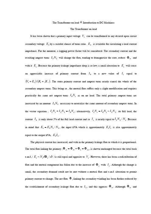
The Transformer on load ﹠Introduction to DC Machine sThe Transformer on loadIt has been shown that a primary input voltage 1V can be transformed to any desired open-circuit secondary voltage 2E by a suitable choice of turns ratio. 2E is available for circulating a load current impedance. For the moment, a lagging power factor will be considered. The secondary current and the resulting ampere-turns 22N I will change the flux, tending to demagnetize the core, reduce m Φ and with it 1E . Because the primary leakage impedance drop is so low, a small alteration to 1E will cause an appreciable increase of primary current from 0I to a new value of 1I equal to ()()i jX R E V ++111/. The extra primary current and ampere-turns nearly cancel the whole of the secondary ampere-turns. This being so , the mutual flux suffers only a slight modification and requires practically the same net ampere-turns 10N I as on no load. The total primary ampere-turns are increased by an amount 22N I necessary to neutralize the same amount of secondary ampere-turns. In the vector equation , 102211N I N I N I =+; alternatively, 221011N I N I N I -=. At full load, the current 0I is only about 5% of the full-load current and so 1I is nearly equal to 122/N N I . Because in mind that 2121/N N E E =, the input kV A which is approximately 11I E is also approximately equal to the output kV A, 22I E .The physical current has increased, and with in the primary leakage flux to which it is proportional. The total flux linking the primary ,111Φ=Φ+Φ=Φm p , is shown unchanged because the total back e.m.f.,(dt d N E /111Φ-)is still equal and opposite to 1V . However, there has been a redistribution of flux and the mutual component has fallen due to the increase of 1Φ with 1I . Although the change is small, the secondary demand could not be met without a mutual flux and e.m.f. alteration to permit primary current to change. The net flux s Φlinking the secondary winding has been further reduced by the establishment of secondary leakage flux due to 2I , and this opposes m Φ. Although m Φ and2Φ are indicated separately , they combine to one resultant in the core which will be downwards at the instant shown. Thus the secondary terminal voltage is reduced to dt d N V S /22Φ-= which can be considered in two components, i.e. dt d N dt d N V m //2222Φ-Φ-=or vectorially 2222I jX E V -=. As for the primary, 2Φ is responsible for a substantially constant secondaryleakage inductance 222222/Λ=ΦN i N . It will be noticed that the primary leakage flux is responsiblefor part of the change in the secondary terminal voltage due to its effects on the mutual flux. The two leakage fluxes are closely related; 2Φ, for example, by its demagnetizing action on m Φ has caused the changes on the primary side which led to the establishment of primary leakage flux.If a low enough leading power factor is considered, the total secondary flux and the mutual flux are increased causing the secondary terminal voltage to rise with load. p Φ is unchanged in magnitude from the no load condition since, neglecting resistance, it still has to provide a total back e.m.f. equal to 1V . It is virtually the same as 11Φ, though now produced by the combined effect of primary and secondary ampere-turns. The mutual flux must still change with load to give a change of 1E and permit more primary current to flow. 1E has increased this time but due to the vector combination with 1V there is still an increase of primary current.Two more points should be made about the figures. Firstly, a unity turns ratio has been assumed for convenience so that '21E E =. Secondly, the physical picture is drawn for a different instant of time from the vector diagrams which show 0=Φm , if the horizontal axis is taken as usual, to be the zero time reference. There are instants in the cycle when primary leakage flux is zero, when the secondary leakage flux is zero, and when primary and secondary leakage flux is zero, and when primary and secondary leakage fluxes are in the same sense.The equivalent circuit already derived for the transformer with the secondary terminals open, can easily be extended to cover the loaded secondary by the addition of the secondary resistance and leakage reactance.Practically all transformers have a turns ratio different from unity although such an arrangement issometimes employed for the purposes of electrically isolating one circuit from another operating at the same voltage. To explain the case where 21N N ≠ the reaction of the secondary will be viewed from the primary winding. The reaction is experienced only in terms of the magnetizing force due to the secondary ampere-turns. There is no way of detecting from the primary side whether 2I is large and 2N small or vice versa, it is the product of current and turns which causes the reaction. Consequently, a secondary winding can be replaced by any number of different equivalent windings and load circuits which will give rise to an identical reaction on the primary .It is clearly convenient to change the secondary winding to an equivalent winding having the same number of turns 1N as the primary.With 2N changes to 1N , since the e.m.f.s are proportional to turns, 2212)/('E N N E = which is the same as 1E .For current, since the reaction ampere turns must be unchanged 1222'''N I N I = must be equal to 22N I .i.e. 2122)/(I N N I =.For impedance , since any secondary voltage V becomes V N N )/(21, and secondary current I becomes I N N )/(12, then any secondary impedance, including load impedance, must become I V N N I V /)/('/'221=. Consequently, 22212)/('R N N R = and 22212)/('X N N X = .If the primary turns are taken as reference turns, the process is called referring to the primary side. There are a few checks which can be made to see if the procedure outlined is valid.For example, the copper loss in the referred secondary winding must be the same as in the original secondary otherwise the primary would have to supply a different loss power. ''222R I must be equal to 222R I . )222122122/()/(N N R N N I ∙∙ does in fact reduce to 222R I .Similarly the stored magnetic energy in the leakage field )2/1(2LI which is proportional to 22'X I will be found to check as ''22X I . The referred secondary 2212221222)/()/(''I E N N I N N E I E kVA =∙==.The argument is sound, though at first it may have seemed suspect. In fact, if the actual secondarywinding was removed physically from the core and replaced by the equivalent winding and load circuit designed to give the parameters 1N ,'2R ,'2X and '2I , measurements from the primary terminals would be unable to detect any difference in secondary ampere-turns, kVA demand or copper loss, under normal power frequency operation.There is no point in choosing any basis other than equal turns on primary and referred secondary, but it is sometimes convenient to refer the primary to the secondary winding. In this case, if all the subscript 1’s are interchanged for the subscript 2’s, the necessary referring constants are easily found; e.g. 2'1R R ≈,21'X X ≈; similarly 1'2R R ≈ and 12'X X ≈.The equivalent circuit for the general case where 21N N ≠ except that m r has been added to allow for iron loss and an ideal lossless transformation has been included before the secondary terminals to return '2V to 2V .All calculations of internal voltage and power losses are made before this ideal transformation is applied. The behaviour of a transformer as detected at both sets of terminals is the same as the behaviour detected at the corresponding terminals of this circuit when the appropriate parameters are inserted. The slightly different representation showing the coils 1N and 2N side by side with a core in between is only used for convenience. On the transformer itself, the coils are , of course , wound round the same core.Very little error is introduced if the magnetising branch is transferred to the primary terminals, but a few anomalies will arise. For example ,the current shown flowing through the primary impedance is no longer the whole of the primary current. The error is quite small since 0I is usually such a small fraction of 1I . Slightly different answers may be obtained to a particular problem depending on whether or not allowance is made for this error. With this simplified circuit, the primary and referred secondary impedances can be added to give: 221211)/(Re N N R R += and 221211)/(N N X X Xe +=It should be pointed out that the equivalent circuit as derived here is only valid for normal operation at power frequencies; capacitance effects must be taken into account whenever the rate of change of voltage would give rise to appreciable capacitance currents, dt CdV I c /=. They are important at high voltages and at frequencies much beyond 100 cycles/sec. A further point is not theonly possible equivalent circuit even for power frequencies .An alternative , treating the transformer as a three-or four-terminal network, gives rise to a representation which is just as accurate and has some advantages for the circuit engineer who treats all devices as circuit elements with certain transfer properties. The circuit on this basis would have a turns ratio having a phase shift as well as a magnitude change, and the impedances would not be the same as those of the windings. The circuit would not explain the phenomena within the device like the effects of saturation, so for an understanding of internal behaviour .There are two ways of looking at the equivalent circuit:(a) viewed from the primary as a sink but the referred load impedance connected across '2V ,or (b) viewed from the secondary as a source of constant voltage 1V with internal drops due to 1Re and 1Xe . The magnetizing branch is sometimes omitted in this representation and so the circuit reduces to a generator producing a constant voltage 1E (actually equal to 1V ) and having an internal impedance jX R + (actually equal to 11Re jXe +).In either case, the parameters could be referred to the secondary winding and this may save calculation time .The resistances and reactances can be obtained from two simple light load tests.Introduction to DC MachinesDC machines are characterized by their versatility. By means of various combination of shunt, series, and separately excited field windings they can be designed to display a wide variety of volt-ampere or speed-torque characteristics for both dynamic and steadystate operation. Because of the ease with which they can be controlled , systems of DC machines are often used in applications requiring a wide range of motor speeds or precise control of motor output.The essential features of a DC machine are shown schematically. The stator has salient poles and is excited by one or more field coils. The air-gap flux distribution created by the field winding is symmetrical about the centerline of the field poles. This axis is called the field axis or direct axis.As we know , the AC voltage generated in each rotating armature coil is converted to DC in the external armature terminals by means of a rotating commutator and stationary brushes to which the armature leads are connected. The commutator-brush combination forms a mechanical rectifier,resulting in a DC armature voltage as well as an armature m.m.f. wave which is fixed in space. The brushes are located so that commutation occurs when the coil sides are in the neutral zone , midway between the field poles. The axis of the armature m.m.f. wave then in 90 electrical degrees from the axis of the field poles, i.e., in the quadrature axis. In the schematic representation the brushes are shown in quarature axis because this is the position of the coils to which they are connected. The armature m.m.f. wave then is along the brush axis as shown.. (The geometrical position of the brushes in an actual machine is approximately 90 electrical degrees from their position in the schematic diagram because of the shape of the end connections to the commutator.)The magnetic torque and the speed voltage appearing at the brushes are independent of the spatial waveform of the flux distribution; for convenience we shall continue to assume a sinusoidal flux-density wave in the air gap. The torque can then be found from the magnetic field viewpoint.The torque can be expressed in terms of the interaction of the direct-axis air-gap flux per pole d Φ and the space-fundamental component 1a F of the armature m.m.f. wave . With the brushes in the quadrature axis, the angle between these fields is 90 electrical degrees, and its sine equals unity. For a P pole machine 12)2(2a d F P T ϕπ= In which the minus sign has been dropped because the positive direction of the torque can be determined from physical reasoning. The space fundamental 1a F of the sawtooth armature m.m.f. wave is 8/2π times its peak. Substitution in above equation then gives a d a a d a i K i mPC T ϕϕπ==2 Where a i =current in external armature circuit;a C =total number of conductors in armature winding;m =number of parallel paths through winding;And mPC K a a π2=Is a constant fixed by the design of the winding.The rectified voltage generated in the armature has already been discussed before for an elementary single-coil armature. The effect of distributing the winding in several slots is shown in figure ,in which each of the rectified sine waves is the voltage generated in one of the coils, commutation taking place at the moment when the coil sides are in the neutral zone. The generated voltage as observed from the brushes is the sum of the rectified voltages of all the coils in series between brushes and is shown by the rippling line labeled a e in figure. With a dozen or so commutator segments per pole, the ripple becomes very small and the average generated voltage observed from the brushes equals the sum of the average values of the rectified coil voltages. The rectified voltage a e between brushes, known also as the speed voltage, is m d a m d a a W K W mPC e ϕϕπ==2 Where a K is the design constant. The rectified voltage of a distributed winding has the same average value as that of a concentrated coil. The difference is that the ripple is greatly reduced.From the above equations, with all variable expressed in SI units:m a a Tw i e =This equation simply says that the instantaneous electric power associated with the speed voltage equals the instantaneous mechanical power associated with the magnetic torque , the direction of power flow being determined by whether the machine is acting as a motor or generator.The direct-axis air-gap flux is produced by the combined m.m.f. f f i N ∑ of the field windings, the flux-m.m.f. characteristic being the magnetization curve for the particular iron geometry of the machine. In the magnetization curve, it is assumed that the armature m.m.f. wave is perpendicular to the field axis. It will be necessary to reexamine this assumption later in this chapter, where the effects of saturation are investigated more thoroughly. Because the armature e.m.f. is proportional to flux timesspeed, it is usually more convenient to express the magnetization curve in terms of the armature e.m.f. 0a e at a constant speed 0m w . The voltage a e for a given flux at any other speed m w is proportional to the speed,i.e. 00a m m a e w w e Figure shows the magnetization curve with only one field winding excited. This curve can easily be obtained by test methods, no knowledge of any design details being required.Over a fairly wide range of excitation the reluctance of the iron is negligible compared with that of the air gap. In this region the flux is linearly proportional to the total m.m.f. of the field windings, the constant of proportionality being the direct-axis air-gap permeance.The outstanding advantages of DC machines arise from the wide variety of operating characteristics which can be obtained by selection of the method of excitation of the field windings. The field windings may be separately excited from an external DC source, or they may be self-excited; i.e., the machine may supply its own excitation. The method of excitation profoundly influences not only the steady-state characteristics, but also the dynamic behavior of the machine in control systems.The connection diagram of a separately excited generator is given. The required field current is a very small fraction of the rated armature current. A small amount of power in the field circuit may control a relatively large amount of power in the armature circuit; i.e., the generator is a power amplifier. Separately excited generators are often used in feedback control systems when control of the armature voltage over a wide range is required. The field windings of self-excited generators may be supplied in three different ways. The field may be connected in series with the armature, resulting in a shunt generator, or the field may be in two sections, one of which is connected in series and the other in shunt with the armature, resulting in a compound generator. With self-excited generators residual magnetism must be present in the machine iron to get the self-excitation process started.In the typical steady-state volt-ampere characteristics, constant-speed primemovers being assumed. The relation between the steady-state generated e.m.f. a E and the terminal voltage t V isa a a t R I E V -=Where a I is the armature current output and a R is the armature circuit resistance. In a generator, a E is large than t V ; and the electromagnetic torque T is a countertorque opposing rotation.The terminal voltage of a separately excited generator decreases slightly with increase in the load current, principally because of the voltage drop in the armature resistance. The field current of a series generator is the same as the load current, so that the air-gap flux and hence the voltage vary widely with load. As a consequence, series generators are not often used. The voltage of shunt generators drops off somewhat with load. Compound generators are normally connected so that the m.m.f. of the series winding aids that of the shunt winding. The advantage is that through the action of the series winding the flux per pole can increase with load, resulting in a voltage output which is nearly constant. Usually, shunt winding contains many turns of comparatively heavy conductor because it must carry the full armature current of the machine. The voltage of both shunt and compound generators can be controlled over reasonable limits by means of rheostats in the shunt field. Any of the methods of excitation used for generators can also be used for motors. In the typical steady-state speed-torque characteristics, it is assumed that the motor terminals are supplied from a constant-voltage source. In a motor the relation between the e.m.f. a E generated in the armature and the terminal voltage t V isa a a t R I E V +=Where a I is now the armature current input. The generated e.m.f. a E is now smaller than the terminal voltage t V , the armature current is in the opposite direction to that in a motor, and the electromagnetic torque is in the direction to sustain rotation ofthe armature.In shunt and separately excited motors the field flux is nearly constant. Consequently, increased torque must be accompanied by a very nearly proportional increase in armature current and hence by a small decrease in counter e.m.f. to allow this increased current through the small armature resistance. Since counter e.m.f. is determined by flux and speed, the speed must drop slightly. Like the squirrel-cage induction motor ,the shunt motor is substantially a constant-speed motor having about 5 percent drop in speed from no load to full load. Starting torque and maximum torque are limited by the armature current that can be commutated successfully.An outstanding advantage of the shunt motor is ease of speed control. With a rheostat in the shunt-field circuit, the field current and flux per pole can be varied at will, and variation of flux causes the inverse variation of speed to maintain counter e.m.f. approximately equal to the impressed terminal voltage. A maximum speed range of about 4 or 5 to 1 can be obtained by this method, the limitation again being commutating conditions. By variation of the impressed armature voltage, very wide speed ranges can be obtained.In the series motor, increase in load is accompanied by increase in the armature current and m.m.f. and the stator field flux (provided the iron is not completely saturated). Because flux increases with load, speed must drop in order to maintain the balance between impressed voltage and counter e.m.f.; moreover, the increase in armature current caused by increased torque is smaller than in the shunt motor because of the increased flux. The series motor is therefore a varying-speed motor with a markedly drooping speed-load characteristic. For applications requiring heavy torque overloads, this characteristic is particularly advantageous because the corresponding power overloads are held to more reasonable values by the associated speed drops. Very favorable starting characteristics also result from the increase in flux with increased armature current.In the compound motor the series field may be connected either cumulatively, so that its.m.m.f.adds to that of the shunt field, or differentially, so that it opposes. The differential connection is very rarely used. A cumulatively compounded motor hasspeed-load characteristic intermediate between those of a shunt and a series motor, the drop of speed with load depending on the relative number of ampere-turns in the shunt and series fields. It does not have the disadvantage of very high light-load speed associated with a series motor, but it retains to a considerable degree the advantages of series excitation.The application advantages of DC machines lie in the variety of performance characteristics offered by the possibilities of shunt, series, and compound excitation. Some of these characteristics have been touched upon briefly in this article. Still greater possibilities exist if additional sets of brushes are added so that other voltages can be obtained from the commutator. Thus the versatility of DC machine systems and their adaptability to control, both manual and automatic, are their outstanding features.负载运行的变压器及直流电机导论负载运行的变压器通过选择合适的匝数比,一次侧输入电压1V 可任意转换成所希望的二次侧开路电压2E 。
本科毕业设计(论文)中英文对照翻译院(系部)电气工程与自动化学院专业名称电气工程及其自动化年级班级03级2班学生姓名指导老师电力系统1 电力的技术特点电力具有独特的技术特点,这使得电力工业具有独特的行业特点。
1.无形性。
用户不能用人体感官直接察觉千瓦时的用电量。
2.质量。
供电质量可由供电连续性或供电可靠性、在标准电压等级下的电压均等性、交流电压频率的正确不变性来度量。
3.电力的贮存。
与大多数行业不同,电力部门必须随时根据用电的需求生产出电力来,因为电能无法贮存。
4.对供电负责。
电由电力部门输送到用户,因此必须对安全、可靠供电负责。
5.对公众的安全。
电力部门须对公众及其技术人员提供稳妥的保护。
2 电力系统的规划预期到电力部门的供电负荷将持续增长,电力系统的容量也持续增大。
远期规划主要是保证这种扩建在技术上是适宜的,在造价上是合理的,与增长模式是相符的。
远期规划者碰到的困难包括:不同地域和不同时间负荷增长的不确定性、新发明新技术发展的可能性。
优异的系统规划要努力做到全系统设计的最优化,而不能为了系统某部分造价的最小化而不顾其它部分的影响。
近年来,已经强调了规划和运行的经济性。
现在则越来越强调可靠性和环境方面的因素。
在作出规划前,须要仔细考虑许多因素:(1)设备的决策具有远期效应,这需要15—25年的预期和研究。
(2)有许多发电途径可选择:核电、基荷火电、中等规模燃气轮机发电或水电,以及大型、中型、小型电厂和各种形式的蓄能。
(3)有多种送电途径可选择,例如由交流或直流,架空线或地下电缆送电并有各种电压等级。
(4)规划决策受负荷管理技术和负荷模式的影响。
(5)有关因素存在不确定性。
如将来燃料价格货币的利率资金的来源设备的强迫停运率新技术环境的要求。
3 电力分配3.1 最初的分配系统发电厂和最后的各支路之间的分配线路叫做最初的分配系统。
在这两个电力系统之间传输有多种方法. 其中最常见的两种方法是辐射式和环绕式。
智能控制系统中英文资料对照外文翻译文献附录一:外文摘要The development and application of Intelligence controlsystemModern electronic products change rapidly is increasingly profound impact on people's lives, to people's life and working way to bring more convenience to our daily lives, all aspects of electronic products in the shadow, single chip as one of the most important applications, in many ways it has the inestimable role. Intelligent control is a single chip, intelligent control of applications and prospects are very broad, the use of modern technology tools to develop an intelligent, relatively complete functional software to achieve intelligent control system has become an imminent task. Especially in today with MCU based intelligent control technology in the era, to establish their own practical control system has a far-reaching significance so well on the subject later more fully understanding of SCM are of great help to.The so-called intelligent monitoring technology is that:" the automatic analysis and processing of the information of the monitored device". If the monitored object as one's field of vision, and intelligent monitoring equipment can be regarded as the human brain. Intelligent monitoring with the aid of computer data processing capacity of the powerful, to get information in the mass data to carry on the analysis, some filtering of irrelevant information, only provide some key information. Intelligent control to digital, intelligent basis, timely detection system in the abnormal condition, and can be the fastest and best way to sound the alarm and provide usefulinformation, which can more effectively assist the security personnel to deal with the crisis, and minimize the damage and loss, it has great practical significance, some risk homework, or artificial unable to complete the operation, can be used to realize intelligent device, which solves a lot of artificial can not solve the problem, I think, with the development of the society, intelligent load in all aspects of social life play an important reuse.Single chip microcomputer as the core of control and monitoring systems, the system structure, design thought, design method and the traditional control system has essential distinction. In the traditional control or monitoring system, control or monitoring parameters of circuit, through the mechanical device directly to the monitored parameters to regulate and control, in the single-chip microcomputer as the core of the control system, the control parameters and controlled parameters are not directly change, but the control parameter is transformed into a digital signal input to the microcontroller, the microcontroller according to its output signal to control the controlled object, as intelligent load monitoring test, is the use of single-chip I / O port output signal of relay control, then the load to control or monitor, thus similar to any one single chip control system structure, often simplified to input part, an output part and an electronic control unit ( ECU )Intelligent monitoring system design principle function as follows: the power supply module is 0~220V AC voltage into a0 ~ 5V DC low voltage, as each module to provide normal working voltage, another set of ADC module work limit voltage of 5V, if the input voltage is greater than 5V, it can not work normally ( but the design is provided for the load voltage in the 0~ 5V, so it will not be considered ), at the same time transformer on load current is sampled on the accused, the load current into a voltage signal, and then through the current - voltage conversion, and passes through the bridge rectification into stable voltage value, will realize the load the current value is converted to a single chip can handle0 ~ 5V voltage value, then the D2diode cutoff, power supply module only plays the role of power supply. Signal to the analog-to-digital conversion module, through quantization, coding, the analog voltage value into8bits of the digital voltage value, repeatedly to the analog voltage16AD conversion, and the16the digital voltage value and, to calculate the average value, the average value through a data bus to send AT89C51P0, accepted AT89C51 read, AT89C51will read the digital signal and software setting load normal working voltage reference range [VMIN, VMAX] compared with the reference voltage range, if not consistent, then the P1.0 output low level, close the relay, cut off the load on the fault source, to stop its sampling, while P1.1 output high level fault light, i.e., P1.3 output low level, namely normal lights. The relay is disconnected after about 2minutes, theAT89C51P1.0outputs high level ( software design), automatic closing relay, then to load the current regular sampling, AD conversion, to accept the AT89C51read, comparison, if consistent, then the P1.1 output low level, namely fault lights out, while P1.3 output high level, i.e. normal lamp ( software set ); if you are still inconsistent, then the need to manually switch S1toss to" repair" the slip, disconnect the relay control, load adjusting the resistance value is: the load detection and repair, and then close the S1repeatedly to the load current sampling, until the normal lamp bright, repeated this process, constantly on the load testing to ensure the load problems timely repair, make it work.In the intelligent load monitoring system, using the monolithic integrated circuit to the load ( voltage too high or too small ) intelligent detection and control, is achieved by controlling the relay and transformer sampling to achieve, in fact direct control of single-chip is the working state of the relay and the alarm circuit working state, the system should achieve technical features of this thesis are as follows (1) according to the load current changes to control relays, the control parameter is the load current, is the control parameter is the relay switch on-off and led the state; (2) the set current reference voltage range ( load normal working voltage range ), by AT89C51 chip the design of the software section, provide a basis for comparison; (3) the use of single-chip microcomputer to control the light-emitting diode to display the current state of change ( normal / fault / repair ); specific summary: Transformer on load current is sampled, a current / voltage converter, filter, regulator, through the analog-digital conversion, to accept the AT89C51chip to read, AT89C51 to read data is compared with the reference voltage, if normal, the normal light, the output port P.0high level, the relay is closed, is provided to the load voltage fault light; otherwise, P1.0 output low level, The disconnecting relay to disconnect the load, the voltage on the sampling, stop. Two minutes after closing relay, timing sampling.System through the expansion of improved, can be used for temperature alarm circuit, alarm circuit, traffic monitoring, can also be used to monitor a system works, in the intelligent high-speed development today, the use of modern technology tools, the development of an intelligent, function relatively complete software to realize intelligent control system, has become an imminent task, establish their own practical control system has a far-reaching significance. Micro controller in the industry design and application, no industry like intelligent automation and control field develop so fast. Since China and the Asian region the main manufacturing plant intelligence to improve the degree of automation, new technology to improve efficiency, have important influence on the product cost. Although the centralized control can be improved in any particular manufacturing process of the overall visual, but not for those response and processingdelay caused by fault of some key application.Intelligent control technology as computer technology is an important technology, widely used in industrial control, intelligent control, instrument, household appliances, electronic toys and other fields, it has small, multiple functions, low price, convenient use, the advantages of a flexible system design. Therefore, more and more engineering staff of all ages, so this graduate design is of great significance to the design of various things, I have great interest in design, this has brought me a lot of things, let me from unsuspectingly to have a clear train of thought, since both design something, I will be there a how to design thinking, this is very important, I think this job will give me a lot of valuable things.中文翻译:智能控制系统的开发应用现代社会电子产品日新月异正在越来越深远的影响着人们的生活,给人们的生活和工作方式带来越来越大的方便,我们的日常生活各个方面都有电子产品的影子,单片机作为其中一个最重要的应用,在很多方面都有着不可估量的作用。

中英文对照外文翻译文献(文档含英文原文和中文翻译)DC Switching Power Supply Protection TechnologyAbstract: The DC switching power supply protection system, protection s ystem design principles and machine protection measures, an analysis of switching power supply in the range of protected characteristics and its d esign methodology, introduced a number of practical protection circuit. Keywords: switching power supply protection circuit system design A、Introduction.DC switching regulator used in the price of more expensive high-powerswitching devices, the control circuit is also more complex, In addition, th e load switching regulators are generally used a large number of highly in tegrated electronic systems installed devices. Transistors and integrated device tolerance electricity, less heat shocks. Switching Regulators theref ore should take into account the protection of voltage regulators and loa d their own safety. Many different types of circuit protection, polarity pro tection, introduced here, the program protection, over-current protectio n, over-voltage protection, under-voltage protection and over-temperatu re protection circuit. Usually chosen to be some combination of protectio n, constitutes a complete protection system.B、Polarity protectionDC switching regulator input is generally not regulated DC power supply. Operating errors or accidents as a result of the situation will take its wron g polarity; switching power supply will be damaged. Polarity protection p urposes, is to make the switching regulator only when the correct polarit y is not connected to DC power supply regulator to work at. Connecting a single device can achieve power polarity protection. Since the diode D t o flow through switching regulator input total current, this circuit applied in a low-power switching regulator more suitable. Power in the larger oc casion, while the polarity protection circuit as a procedure to protect a li nk, save the power required for polarity protection diodes, power consumption will be reduced. In order to easy to operate, make it easier to ide ntify the correct polarity or not, collect the next light.C、Procedures to protectSwitching power supply circuit is rather complicated, basically can be divi ded into low-power and high-power part of the control part of the switch . Switch is a high-power transistors, for the protection of the transistor s witch is turned on or off power safety, we must first modulator, amplifier and other low-power control circuit. To this end, the boot to ensure the correct procedures. Switching Regulators generally take the input of a sm all inductor, the input filter capacitor. Moment in the boot, filter capacito r will flow a lot of surge current, the surge current can be several times m ore than the normal input current. Such a large surge current may contac t the general power switch or relay contact melting, and the input fuse. I n addition, the capacitor surge current will damage to shorten the life sp an of premature damage. To this end, the boot should be access to a curr ent limiting resistor, through the current limiting resistor to capacitor cha rging. In order not to make the current limiting resistor excessive power c onsumption, thus affecting the normal switching regulator, and the transi ent process in the boot after a short period then automatically relays it t o DC power supply directly to the switching regulator power supply. This circuit switching regulator called a "soft start" circuit. Switching regulator control circuit of the logic components required or op-amp auxiliary p ower supply. To this end, the auxiliary power supply must be in the switc h circuit. This control circuit can be used to ensure the boot. Normal boo t process is: to identify the polarity of input power, voltage protection pr ocedures → boot → auxiliary power supply circuit and through current li miting resistor R of the switching regulator input capacitor C →charge modulation switching regulator circuit, → short-circuit current limiting re sistor stability switching regulator. In the switching regulator, the machi nes just because the output capacitance, and charge to the rated output voltage value of the need for a certain period of time. During this time, s ampling the output amplifier with low input voltage sampling, closed-loo p regulation characteristics of the system will force the switching of the t ransistor conduction time lengthened, so that switching transistor during this period will tend to continuous conduction, and easily damaged. To t his end, the requirements of this paragraph in the boot time, the switch t o switch the output modulation circuit transistor base drive signal of the pulse width modulation, can guarantee the switching transistor by the cu t-off switches are becoming more and more normal state, therefore the protection of the setting up of a boot to tie in with the soft start.D、Over-current protectionWhen the load short-circuit, overload control circuit failure or unforesee n circumstances, such as would cause the flow of switching voltage regulator transistor current is too large, so that increased power tubes, fever, i f there is no over-current protection device, high power switching transis tor may be damaged. Therefore, the switching regulator in the over-curr ent protection is commonly used. The most economical way is to use sim ple fuse. As a result of the heat capacity of small transistors, general fuse protection in general can not play a role in the rapid fuse common fuse. This method has the advantage of the protection of vulnerable, but it ne eds to switch transistor in accordance with specific security requirements of the work area to select the fuse specifications. This disadvantage is ov er-current protection measures brought about by the inconvenience of fr equent replacement of fuses. Linear voltage regulator commonly used i n the protection and current limiting to protect the cut-off in the switchi ng regulator can be applied. However, according to the characteristics of switching regulators, the protection circuit can not directly control the ou tput transistor switches, and over current protection must be converted t o pulse output commands to control the modulator to protect the transis tor switch. In order to achieve over-current protection are generally requ ired sampling resistor in series in the circuit, this will affect the efficiency of power supply, so more for low-power switching regulator of occasions. In the high-power switching power supply, by taking into account the po wer consumption should be avoided as far as possible access to the sam pling resistor. Therefore, there will usually be converted to over-current protection, and under-voltage protection.F、Under-voltage protectionOutput voltage below the value to reflect the input DC power supply, swi tching regulator output load internal or unusual occurrence. Input DC po wer supply voltage drops below the specified value would result in switc hing regulator output voltage drops, the input current increases, not only endanger the switching transistor, but also endanger the input power. T herefore, in order to set up due to voltage protection. Due to simple volt age protection. When no voltage regulator input normal, ZD breakdow n voltage regulator tube, transistors V conduction, the relay action, conta ct pull-in, power-switching regulator. When the input below the minimu m allowable voltage value, the regulator tube ZD barrier, V cut-off, conta ct Kai-hop, switching regulator can not work. Internal switching regula tor, as the control switch transistor circuit disorders or failure will decrea se the output voltage; load short-circuit output voltage will also decline.Especially in the reversed-phase step-up or step-up switching regulator D C voltage of the protection due to over-current protection with closely re lated and therefore more important. Implementation of Switching Regula tors in the termination of the output voltage comparators. Normally, th ere is no comparator output, once the voltage drops below the allowable value in the comparator on the flip, drive alarm circuit; also fed back to the switching regulator control circuit, so that switching transistor cut-off or cut off the input power.G、Over-temperature protectionSwitching regulator and the high level of integration of light-weight small volume, with its unit volume greatly increased the power density, power supply components to its work within the requirements of the ambient t emperature is also a corresponding increase. Otherwise, the circuit perfo rmance will deteriorate premature component failure. Therefore, in high -power switching regulator should be set up over-temperature protectio n. Relays used to detect the temperature inside the power supply temp erature, when the internally generated power supply overheating, the te mperature of the relay on the action, so that whole circuit in a warning al arm, and the realization of the power supply over-temperature protectio n. Temperature relay can be placed in the vicinity of the switching transis tor, the general high-power tube shell to allow the maximum temperatur e is 75 ℃, adjust the temperature setting to 60 ℃. When the shell after t he temperature exceeds the allowable value to cut off electrical relay on the switch protection. Semiconductor switching device thermal "hot thirs tier," in the over-temperature protection, played an important role. It can be used as directed circuit temperature. Under the control of p-ho t-gate thirstier (TT102) characteristics, by RT value to determine the tem perature of the device turn-on, RT greater the temperature the lower theturn-on. When placed near the power switching transistor or power devi ce, it will be able to play the role of temperature instructions. When the power control the temperature of the shell or the internal device temper ature exceeds the allowed value, the heat conduction thirstier on, so that LED warning light. If the opt coupler with, would enable the whole circui t alarm action to protect the switching regulator. It can also be used as a power transistor as the over-temperature protection, crystal switch the b ase current by n-type gate control thirstier TT201 thermal bypass, cut-off switch to cut off the collector current to prevent overheating.H、 The future development of relay protectionProtection technology to future trends is computerized, network, intellig ent, protection and control, measurement and data communications inte gration development.1) ComputerizedAlong with the rapid development of computer hardware, microcompute r protection and development in hardware. Former north electricity insti tute of computer line protection hardware has experienced three develo pment stages: from eight single CPU structure of the microcomputer rela y protection, less than 5 years time to develop more CPU structure, and t o develop the large don't bus module, performance greatly improve mod ule structure, widely used. Huazhong university of science and technolog y development of microcomputer protection from 8 bits CPU, is the corepart in polymerizing-kettle development based on 32-bit microcomputer protection. Nanjing institute of electrical automation began a 16-bit CP U is developed on the basis of computer line protection, has been wides pread in the study, also protect the hardware system 32 bits. The devel opment of southeast university computer hardware and equipment to pr otect and improve through a lot. Tianjin university is a start with more th an 16 bits CPU developed on the basis of computer line protection, whic h began in 1988 study 32-bit digital signal processor (DSP) for the protect ion and control, measuring devices, microcomputer integrated with Zhuh ai jin electrical automation equipment company developed into a fully fu nctional 32-bit big modules, a module is a small computer. Using 32-bit microcomputer chip is not only because the accuracy and precision of th e A/D converter by the resolution limit, more than 16 when converting s peed and cost is unacceptable, More important is the 32-bit microcompu ter chip with high integrity, high frequency and computing speed and lar ge space, rich addressing the command system and more input output. T he CPU registers, data bus, the address bus are 32-bit memory managem ent function, and memory protection function and tasks, and the convers ion function will Cache (Cache) and floating-point components are integr ated in the CPU.2)NetworkPower system of microcomputer protection requirement, besides improving the basic function of protection, also should have the capacity of the fault information and data storage space, long-term fast data processing function, strong communication ability, and other protection and control devices and the whole system by sharing network dispatching data, infor mation and network resources, the ability to program in a high-level lang uage, etc. This requires microcomputer protection device is equivalent to a PC. In the early development of computer to protect, once thought to use a small computer finish relay protection device. Due to the large size, then minicomputers high cost and reliability of this idea is not reality. No w, with microprocessor-based protection function of similar size, speed, work-managing machine greatly exceed the storage capacity of 9 minicomputer, therefore, make use of the relay protection sets polymeriz ing-kettle time is ripe, this is the development direction of the microcom puter relay protection. Tianjin University has developed with microproc essor-based protection device with an identical structure reform polymer izing-kettle of relay protection device. This device has several advantages : (1) 486PC machine can meet all the functions of the current and future demands of microcomputer protection function. (2) dimension and struc ture and the current protection device, exquisite workmanship, shockpro of, prevent overheating, preventing electromagnetic interference ability i s strong, can run in very bad working environment, cost can be accepted.(3) using STD bus or PC bus, hardware modular, for different protection can be arbitrarily choose different modules, flexible configuration, easy ex tension. The microcomputer relay protection device, computerized is irr eversible trend. But how to better satisfy power system, how to further i mprove the reliability of the relay protection, and how to obtain more ec onomic benefit and social benefit, still must specifically in-depth researc h. 820 networks The computer network information and data communi cation tool has become the mainstay of the information age, make huma n production technology and social life of the fundamental changes have taken place. It is deeply affect all industries, as well as various industry pr ovides powerful means of communication. So far, in addition to the differ ential protection disoperation and protection of the relay protection devi ce, all can only protect the electricity installation reaction. Protection fun ction is limited, reduce accidents resection fault components. This is mai nly due to the lack of data communications. Strong Foreign had put forw ard the concept of protection system, which was mainly refers to the safe ty automatic device. Because of the relay protection function not only fa ult components and limit resection impact accident (this is to ensure p riority), the safe and stable operation of the whole system. This requires each protection unit can be altogetherI、ConclusionDiscussed above in the switching regulator of a variety of conservation, a nd introduces a number of specific ways to achieve. Of a given switchingpower supply is concerned, but also protection from the whole to consid er the following points:1) The switching regulator used in the switching transistor in the DC secu rity restrictions on the work of regional work. The transistor switches sel ected by the manual available transistors get DC safe working area. Accor ding to the maximum collector current to determine the input value of o ver-current protection. However, the instantaneous maximum value sho uld be converted to the average current. At rated output current and out put voltage conditions, the switch of the dynamic load line does not exce ed a safe working area DC maximum input voltage, input over-voltage pr otection is the voltage value.2) The switching regulator output limit given by the technical indicators within. Work within the required temperature range, the switching regul ator's output voltage, the lower limit of the output is off, due to the volta ge value of voltage protection. Over-current protection can be based on t he maximum output current to determine. False alarm in order not to pr otect the value of a certain margin to remain appropriate.3) From the above two methods to determine the protection after the p ower supply device in accordance with the needs of measures to determi ne the alarm. Measures the general alarm sound and light alarm two poli ce. Voice of the police applied to more complex machines, power supply parts and do not stand out in a place, it can give staff an effective warning of failure; optical Police instructions can be eye-catching and fault alar m and pointed out that the fault location and type. Protection measur es should be protected as to determine the location. In the high-power, multi-channel power supply, always paying, DC circuit breakers, relays, et c. high-sensitivity auto-protection measures, to cut off the input power s upply to stop working the system from damage. Through the logic contro l circuit to make the appropriate program cut-off switch transistor is sens itive it is convenient and economic. This eliminated large, long response t ime, the price of your high-power relay or circuit breaker.4) The power of putting in the protection circuit will be affected after the reliability of the system, for which want to protect the reliability of the ci rcuit itself is higher in order to improve the reliability of the entire power system, thereby increasing its own power supply MTBF. This requires the protection of strict logic, the circuit is simple, at least components, In ad dition to the protection circuit should also be considered a failure of mai ntenance of their difficulty and their power to protect the damage. The refore, we must be comprehensive and systematic consideration of a vari ety of switching power supply protection measures to ensure the normal operation of switching power supplies and high-efficiency and high relia bility.直流开关稳压电源的保护技术摘要:讨论了直流开关稳压电源的保护系统,提出保护系统设计的原则和整机保护的措施,分析了开关稳压电源中的各种保护的特点及其设计方法,介绍了几种实用保护电路。
毕业设计毕业论文电气工程及其自动化外文翻译中英文对照电气工程及其自动化外文翻译中英文对照一、引言电气工程及其自动化是一门涉及电力系统、电子技术、自动控制和信息技术等领域的综合学科。
本文将翻译一篇关于电气工程及其自动化的外文文献,并提供中英文对照。
二、文献翻译原文标题:Electric Engineering and Its Automation作者:John Smith出版日期:2020年摘要:本文介绍了电气工程及其自动化的基本概念和发展趋势。
首先,介绍了电气工程的定义和范围。
其次,探讨了电气工程在能源领域的应用,包括电力系统的设计和运行。
然后,介绍了电气工程在电子技术领域的重要性,包括电子设备的设计和制造。
最后,讨论了电气工程与自动控制和信息技术的结合,以及其在工业自动化和智能化领域的应用。
1. 介绍电气工程是一门研究电力系统和电子技术的学科,涉及发电、输电、配电和用电等方面。
电气工程的发展与电力工业的发展密切相关。
随着电力需求的增长和电子技术的进步,电气工程的重要性日益凸显。
2. 电气工程在能源领域的应用电气工程在能源领域的应用主要包括电力系统的设计和运行。
电力系统是由发电厂、输电线路、变电站和配电网络等组成的。
电气工程师负责设计和维护这些设施,以确保电力的可靠供应。
3. 电气工程在电子技术领域的重要性电气工程在电子技术领域的重要性体现在电子设备的设计和制造上。
电子设备包括电脑、手机、电视等消费电子产品,以及工业自动化设备等。
电气工程师需要掌握电子电路设计和数字信号处理等技术,以开发出高性能的电子设备。
4. 电气工程与自动控制和信息技术的结合电气工程与自动控制和信息技术的结合是电气工程及其自动化的核心内容。
自动控制技术可以应用于电力系统的运行和电子设备的控制,以提高系统的稳定性和效率。
信息技术则可以用于数据采集、处理和传输,实现对电力系统和电子设备的远程监控和管理。
5. 电气工程在工业自动化和智能化领域的应用电气工程在工业自动化和智能化领域的应用越来越广泛。
基于PWM控制直流调速系统的设计摘要:本文基于PWM的双闭环直流调速系统进行了研究,并设计出应用于直流电动机的双闭环直流调速系统。
首先描述了变频器的发展历程,提出了PWM调速方法的优势,指出了未来PWM调速方法的发展前景,点出了研究PWM调速方法的意义。
应用于直流电机的调速方式很多,其中以PWM变频调速方式应用最为广泛,而PWM变频器中,H型PWM变频器性能尤为突出,作为本次设计的基础理论,本文将对PWM的理论进行详细论述。
在此基础上,本文将做出SG3525单片机控制的H型PWM变频调速系统的整体设计,然后对各个部分分别进行论证,力图在每个组成单元上都达到最好的系统性能。
关键词:直流调速;双闭环;PWM ;SG3525 ;直流电机引言:目前,随着大功率电力电子器件的迅速发展,交流变频调速技术已日臻成熟并日渐成为实际应用的主流,但这并不意味着传统的直流调速技术已经完全退出了实际应用的舞台。
相反,近几年交流变频调速在控制精度的提高上遇到了瓶颈,于是直流调速的优势就显现了出来。
直流调速仍然是目前最可靠,精度最高的调速方法。
譬如在对控制精度有较高要求的造纸,转台,轮机定位等系统中仍离不开直流调速装置,因此加强对直流调速系统的研究还是很有必要的。
鉴于直流调速系统在国民经济和工农业生产以及国防事业中的重要作用,有必要对直流调速系统作进一步的研究和开发。
1 系统设计的技术要求1)直流电动机:型号:DJ15功率:485W电枢电压:220V电枢电流:额定转数:1600rpm2)调速范围:1-12003)起动时超调量:电流超调量:%5≤i σ;转速超调量: %5≤n σ2 系统设计的整体结构3系统设计PWM 系统的优越性 :2) 开关频率高,电流容易连续,谐波少,电机损耗及发热都较小。
3) 低速性能好,稳速精度高,调速范围广,可达到1:10000左右。
4) 如果可以与快速响应的电动机配合,则系统频带宽,动态响应快,动态抗扰能力强。
GALSification of IEEE802.11a BasebandProcessorAbstractIn this paper a Globally Asynchronous Locally Synchronous(GALS) implementation of a complex digital system is discussed.The deployed asynchronous wrappers are based on a novel request-driven technique with embedded time-out function. Each GALS block is fitted with a local clock generator for flushing the internal pipeline stages when there are no incoming requests.This request-driven technique is applied for the‘GALSification’of an IEEE802.11a compliant baseband processor.Details of the GALS partitioning and some additionally developed blocks will be discussed. Furthermore,the designflow,implementation results and power estimation numbers are reported.1IntroductionCurrent trends in System on Chip(SoC)integration impose a number of technical challenges on designers and tools.In the area of wireless communication systems,the number of difficulties for the SoC implementation additionally grows.There is a constant demand for elegant solutions for decreasing power consumption,reducing electromagnetic interference(EMI)between analog and digital circuit blocks,and effective clocking schemes for complex digital systems.Many proposals have been published,but the question which of them will be applied in industrial practice is without answer,yet.GALS techniques attempt to solve some problems of SoC integration.There are many different proposals how to create a stable and efficient GALS system.In papers[1, 2]some of the most popular ways of synchronous system GALSification can be found.Usually,a GALS system consists of a number of locally synchronous blocks surrounded with asynchronous munication between synchronous blocks is performed indirectly via asynchronous wrappers.The current level of GALS development offers a relatively stable framework for the implementation of complex digital systems.However, known GALS techniques may introduce some drawbacks in performance,additional constraints in the system and hardware overhead.On the other hand,all proposed GALS techniques are oriented towards some general architecture with sporadic and not too intensive data transfer on its interfaces.In paper[3]we have introduced a new request-driven GALS technique,optimized for a datapath architecture with bursty,but very intensive data transfer.In this paper the structure of the asynchronous wrapper was described in detail.We decided that after GALSification of relatively small experimental designs,the complete spectrum of advantages and disadvantages of our proposed request-driven GALS technique could be investigated best in a complex datapath application.Since we are working on a system-on-chip implementation of an IEEE802.11a modem,the baseband processor for this standard appeared a good candidate for introducing GALS.In particular the reduction of EMI for this mixed-signal design is in the focus of this work.The baseband processor is a relatively complex design(around700k gates)with an internal datapath structure,which includes sub-blocks like Viterbi decoder,FFT/IFFT processor,and different CORDIC processors.Introducing the GALS mechanisms in this baseband processor was a challenge and some results of this work will be reported here.In the following chapter we will first briefly describe the concept of our request driven GALS technique and possible advantages of using that approach.In the third chapter some basic information about the IEEE802.11a baseband processor will be given and our proposed way of GALS partitioning will be shown.Subsequently,there are the chapters describing our design flow and showing implementation details and results. Finally,some conclusions are drawn.2Concept of Request Driven GALS TechniqueDuring development of our GALS system,a main goal was avoiding the unnecessary transitions and the attendant waste of energy during data transfer betweenGALS blocks,as reported in[3].A secondary issue is to achieve high data throughput with low latency.For a constant input data stream,GALS blocks could operate in a request-driven mode,i.e.it is possible to synchronize the local clock generators with the request input signal.This way no unnecessary transitions are generated.However,for bursty signals, when there is no input activity,the data stored inside the locally synchronouspipeline has to be flushed out.This can be achieved by switching to a mode of operations in which a local clock generator drives the GALS block independently.To control the transition from request driven operation to flushing out data,a time-out function is proposed.The time-out function is triggered when no request has appeared at the input of a GALS block,but data is still stored in internal pipeline stages.Our proposed concept is intended for systems,mainly consisting of point-to-point connections between complex synchronous blocks.The principle architecture of our modified asynchronous wrapper around a locally synchronous module is shown in Fig.1. The locally synchronous circuit can be driven both by the incoming request as well as the local clock signal.The driver of the request input signal is in the asynchronous wrapper of the previous block.It is synchronized with the transferred data,and can be considered as a token carrier.Fig.1.New asynchronous wrapper around locally synchronous block When there is no incoming request signal for a certain period of time(equivalent to Ttime-out),the circuit enters a new state where it can internally generate clocks using alocal ring oscillator.The number of internally generated clocks is set to match the number of cycles needed to empty the locally synchronous pipeline.When there is no valid token in the synchronous block,the local clock will stall and the circuit remains inactive until the next request transition,indicating that a fresh data token has appeared at the input.This way we avoid possible energy waste.More complex and demanding is the scenario when after time-out and starting of the local-clock generation,a new request appears before the synchronous pipeline is emptied. In this case it is necessary to complete the present local clock cycle to prevent metastability at data inputs.Subsequently it is possible to safely hand over clock generation from the local ring oscillator to the input request line.To deal with this situation it is necessary to implement additional circuitry to prevent metastability and hazards in the system.The proposed architecture has several potential advantages.First,and the most obvious is the decreased latency,when the circuit is operating in request-driven mode.In that mode arbitration is not needed and incoming requests are automatically considered as clock signals.Therefore,the performance drop,always present in other GALS solutions, is considerably decreased.This GALS technique offers an efficient power-saving mechanism,similar to clock gating.A particular synchronous block is clocked only when there is new data at the input,or there is a need to flush data from internal pipeline stages.In all other cases there is no activity within this block.In a complex system,designed with the proposed GALS technique,different locally synchronous modules are driven by independent clocks.These clocks will have arbitrary phases due to varying delays in different asynchronous wrappers.During local clock generation they have even different frequencies.In this way EMI and the attendant generation of substrate and supply noise can be reduced.The target applications of the proposed GALS technique are datapath architectures, often deployed for baseband processing in communication systems.For designing‘joins’and‘forks’between asynchronous wrappers,standard asynchronous methods can be employed.Based on the proposed concept asynchronous wrappers have been developed andwere described in[3].In this paper,the reader can find detailed information on the construction of specific individual blocks of the request-driven GALS system.3GALS Baseband ProcessorOur work on GALS implementations is linked to a project that aims to develop a single-chip wireless broadband communication system in the5GHz band,compliant with the IEEE802.11a[4,5]standard.This standard specifies a broadband communication system using Orthogonal Frequency Division Multiplexing(OFDM)with data rates ranging from6to54Mbit/s.The design of the required mixed-signal baseband processor for this standard involves a number of challenges.In particular the global clock tree generation,power consumption,testability,EMI and crosstalk are very demanding issues for the designer.Our request–driven GALS architecture was developed as a possible solution for those problems.Initially,the baseband processor was implemented as an ASIC(Application Specific Integrated Circuit)working synchronously.The natural style of the baseband processor implementation is a datapath architecture.In order to achieve lower power dissipation, the baseband architecture is partitioned in to two blocks:Transmitter and Receiver as shown in Figure2.The standard[4]defines the procedures for receiver and transmitter datapath processing.Our transmitter comprises an input buffer,scrambler,signal field generator, encoder,interleaver,mapper,64-point IFFT(Inverse Fast Fourier Transform)and circuitry for pilot insertion,guard interval insertion,and preamble insertion.Fundamental issues of the receiver are the synchronization mechanism(including64-point FFT-Fast Fourier Transform)and the channel estimation.Other blocks of the receiver are demapper,deinterleaver,descrambler,Viterbi decoder,and additional buffers.The transmitter GALS partitioning is relatively easy to be performed.It is a straightforward datapath architecture,based on a token-flow design technique.The complete baseband transmitter is divided into three modules.This block division takes into account the functionality and complexity of the existing blocks.Block Tx_1comprises80MHz components such as signal field generator,scrambler,encoder,interleaver and mapper.The complexity of the block is about17k gates(inverter equivalent).Block Tx_1is not GALSified due to the complex off-chip interface protocol.The intermediate block Tx_2(20k gates)has to perform pilot insertion and serial to parallel conversion.Additionally,this block performs token rate adaptation because it does receive tokens at a frequency of80Msps and should generate tokens at 20Msps for the subsequent block.This is performed in the following way:when block Tx_2is in request-driven mode,it will collect data at80Msps,but it will not send any token to the neighboring block Tx_3.When a complete data burst for one symbol is collected(48data),the local clock generator,set to20Msps,will initiate data transfer to block Tx_3.Block Tx_3contains very complex(153k gates)processing stages,as IFFT, guard interval insertion and preamble insertion.There is an additional problem in the communication between blocks Tx_2and Tx_3.Generally,communication betweenFig.2.GALS partitioning in baseband processorthose two blocks is performed only in bursts of8data tokens and than block Tx_3has to process this data for the next72cycles without any new incoming data.In order to enable that data transfer free period of72cycles,a special signal is generated in Tx_3that grants a transfer of tokens from the Tx_2side.It is significantly more difficult to introduce GALS in the receiver.There are several reasons for that:The gate count is more than double in comparison with the transmitter. Additionally,the data-flow is much more complicated.The channel estimator is based on a feedback loop.Accordingly,inside the receiver there is a token ring between some blocks(Fig.2).The activation scheme of the baseband processor shows that the receiver stage is processing data all the time,except for the periods when data is transmitted.Most of its own time the receiver will just search for the synchronization sequence(preamble).It appears plausible to implement the tracking synchronizer as a separate GALS block.This block(Rx_1)is comparatively small(80k gates),and if we can limit the switching activities inside the baseband to this block for most of the time,we can keep the power consumption low.Block Rx_2will be activated when coarse synchronisation is reached, and it will perform fine synchronization,frequency error correction,FFT and channel estimation.This block is very complex(235k gates)and all processing is performed at20 Msps.Block Rx_3(168k)will perform demapping,deinterleaving,Viterbi decoding, descrambling and loop backward processing needed for channel estimation.All these blocks naturally operate at80Msps.One of the main challenges in the receiver is how to connect blocks Rx_2and Rx_3, and how to arrange token rate adaptation20Msps→80Msps(in forward data transfer Rx_2→Rx_3),and80Msps→20Msps(in backward data transfer Rx_3→Rx_2). An additional problem is how to synchronize backward data transfer with forward data transfer.A possible solution can be achieved by adding two types of interface blocks: GALS block Rx_TRA and the asynchronous FIFO_TA,as shown in Figure2.This way the backward dataflow is treated as an independent dataflow that creates asynchronous tokens.One task of those blocks is token rate adaptation.Rx_TRA will perform datarate transformation from20Msps to80Msps and FIFO_TA,datarate transformation from80 Msps to20Msps.A critical point in this solution is the control of the asynchronous tokenring.Since the latency in this feedback loop can vary,joins and forks that are created in the system should be designed in such way that operation of the system is not disrupted. Having this in mind,an elegant implementation of the join circuit for the alignment of tokens entering block Rx_2is crucial for making this system functional.Using the proposed partitioning inside the baseband processor it is possible to efficiently implement power saving mechanisms.After reset the baseband processor will produce no switching activity until the first data from outside arrives.After that,in receive mode,most of the time only block Rx_1will be active,trying to find the synchronization pattern.This block is relatively small and the power consumption level will be acceptable.When synchronization is reached,block Rx_1becomes inactive and block Rx_2_will start its activity.This is achieved by switching the token multiplexer that is termed“activation interface”in Fig.2from tracking to the datapath synchronizer.During operation of the receiver,the transmitter is inactive,and vice versa. The amount of power saving achieved by this technique is comparable to clock gating with a similar strategy.The baseband processor will normally be used in a standard synchronous environment.In the transmit mode it has to send data tokens every clock cycle(20Msps) to DACs(Digital to Analog Converters).In receive mode it should absorb data tokens from the ADCs(Analog to Digital Converter)in every clock cycle(20Msps).Connection between a synchronous producer and an asynchronous consumer is achieved in a very simple manner.Due to the request driven property of the asynchronous wrapper,we have just connected the request line of the wrapper with the clock source that creates incoming synchronous data.The only condition that must be fulfilled is the ability of asynchronous wrappers to absorb incoming tokens.Fulfillment of this condition is safely achieved with the insertion of decoupling circuitry in blocks RX_TRA and Tx_2.To connect the asynchronous producer with a synchronous consumer we have used pipeline synchronization[6](blocks Rx_int and Tx_int in Fig.2).This way we can safely connect an asynchronous producer with a synchronous consumer.By addition of more pipeline stages we can easily increase the robustness of our system.In order to efficiently test the designed baseband processor,dedicated units based onBuilt-In Self-Test(BIST)were developed.The implemented BIST circuitry allows us to test both the global system and local block operation.However,the test approach is not in the focus of this paper and it will not be described in detail.4Design Flow and ImplementationThe design flow for developing our GALS system is a combination of the standard synchronous design-flow with specific asynchronous synthesis tools.A graph of our design flow is shown in Fig.3.All synchronous circuits are designed in VHDL and synthFig.3.Design flow for GALS circuits-esized for our in-house0.25μm standard cell library using Synopsys Design Compiler. All asynchronous controllers are modeled as asynchronous finite-state machines and subsequently synthesized using the3D tool[7].3D guarantees hazardfree synthesis of extended and normal burst-mode specifications.The logic equations generated by3D are automatically translated using an own developed converter tool,called3DC,into structural VHDL and subsequently synthesized.Two types of behavioral simulations are carried out.Initially functional verification is performed at the level of VHDL descriptions.This behavioral simulation is to confirm conceptual correctness of the system.Gate-level timing verification is performed after the abstract simulation,on the basis of the synthesized asynchronous parts and VHDL descriptions of the locally synchronous(LS)blocks.This simulation will with high probability prove the correctness of system operation.Nevertheless,it is executed very fast because all LS blocks are still modeled in behavioral VHDL.Subsequently a complete gate-level simulation is performed using both asynchronous and synchronous parts as synthesized netlists.After layout,back-annotation is performed.Behavioral,post-synthesis simulation and back-annotation are performed using a standard VHDL-Verilog simulator.Power estimation based on realistic switching activities is done using the Prime Power tool.All asynchronous wrappers are fitted with a reset logic,necessary for initialization. The local clock generator for each GALS block is designed as a tunable ring oscillator, similar as described in[1].The circuit area for the complete asynchronous wrapper is equivalent to about1.6k inverter gates.From the complete wrapper,the largest area (1166inverter gates)is needed by the tunable clock generator.Designing the clock generators as tunable circuits causes significant hardware overhead.The throughput of the GALS system after synthesis was determined by simulation.In our technology an asynchronous wrapper is operational up to about110Msps.This is well sufficient for our application and fast enough for moderate speed circuitry.The complete system was verified using two different sets of test vectors.One is based on embedded BIST testing and the other one on a real transceiver application in the synchronous environment of a IEEE802.11a modem.Results of the synthesis and power estimation are shown in Table1.It can be observed that synchronous functional blocks occupy more than90%of thetotal area.The BIST circuitry requires around3.6%,interface blocks(asynchronous interfaces and asynchronous to synchronous interfaces)2,9%and asynchronous wrappers only2%of the area.Table1.Area and power distribution in GALS baseband processorBased on the switching activities,in the real transceiver scenario,power estimation with Prime Power has been performed.In the simulation example the baseband processor receives a frame of43bytes and then transmits a standard acknowledge frame of14bytes. Synchronous blocks are using most of the power(around83%).Other important power consumers are asynchronous-to-synchronous interfaces with13,5%,BIST6,6%and asynchronous wrappers with3%.Our GALS baseband processor is taped-out and it is currently under fabrication.The layout of the GALS processor is given in Fig.4.The total number of pins is120and the silicon area including pads is45.1mm2.After layout,the estimated power consumption is324.6mW.This represents a significant increase compared with the after-synthesis power estimation due to the clock-tree and pad insertions.We have also generated a puresynchronous version of the baseband processor that uses clockgating as power-saving method.According to PrimePower,this synchronous baseband is consuming around 393mW in the same transceiver application.That means the GALSification leads to an additional power reduction compared to a synchronous implementation of around17,4%. This result gives us hope that our GALS technique can be used as an effective power saving technique in complex digital systems.yout of the GALS baseband processor5ConclusionsThe design process for GALSification of a complex IEEE802.11a compliant WLAN baseband processor was discussed in this paper.The GALS technique used here is based on a request-driven operation with additional local clock generation.The challenging process of power-optimal GALS partitioning is described.The structure of our GALS baseband processor is complemented with several additional blocks necessary for efficient operation of the system.Finally,the design flow used for this system is described and implementation results are presented.Even though the driving force for this work is the reduction of EMI in the context of a single-chip implementation,it is shown that the GALS implementation consumes less power than a functionally equivalent synchronous version.References1.J.Muttersbach,Globally-Asynchronous Locally-Synchronous Architectures for VLSI Systems,Doctor of Technical Sciences Dissertation,ETH Zurich,Switzerland,2001.2.S.Moore,G.Taylor,R.Mullins,P.Cunningham,P.Robinson,Self Calibrating Clocks for Globally Asynchronous Locally Synchronous System,In Proc.International Conference on Computer Design(ICCD),September2000.3.M.Krsti c´,E.Grass,New GALS Technique for Datapath Architectures,In Proc. International Workshop PATMOS,pp.161-170,September2003.4.IEEE P802.11a/D7.0,Part11:Wireless LAN Medium Access Control(MAC)and Physical Layer(PHY)specifications:High Speed Physical Layer in the5GHz Band,July 1999.5.E.Grass,K.Tittelbach-Helmrich,U.Jagdhold,A.Troya,G.Lippert,O.Krüger,J. Lehmann,K.Maharatna,K.Dombrowski,N.Fiebig,R.Kraemer,P.Mähönen,On the Single-Chip Implementation of a Hiperlan/2and IEEE802.11a Capable Modem,IEEE Personal Communications,Vol.8,No.6,pp.48–57,2001.6.J.Seizovic,Pipeline Synchronization,In Proc.International Symposium of Advanced Research in Asynchronous Circuits and Systems,pp87-96,Nov1994.7.K.Yun,D.Dill,Automatic synthesis of extended burst-mode circuits:Part I and II, IEEE Transactions on Computer-Aided Design,18(2),pp.101-132,February1999.IEEE802.11a系统的GALS形式的基频处理器摘要本文对一个全局异步局部同步(GALS)的复杂的数字系统进行了讨论。
摘要XF 110KV变电所是地区重要变电所,是电力系统110KV电压等级的重要部分。
其设计分为电气一次部分和电气二次部分设计。
一次部分由说明书,计算书与电气工程图组成,说明书和计算书包括变电所总体分析;负荷分析与主变选择;电气主接线设计;短路电流计算;电气设备选择;配电装置选择;变电所总平设计及防雷保护设计。
二次部分由说明书,计算书与电气工程图组成。
说明书和计算书包括整体概述;线路保护的整定计算;主变压器的保护整定计算;电容器的保护整定计算;母线保护和所用变保护设计。
计算书和电气工程图为附录部分。
其中一次部分电气AutoCAD制图六张;二次部分为四张手工制图.本变电所设计为毕业设计课题,以巩固大学所学知识。
通过本次设计,使我对电气工程及其自动化专业的主干课程有一个较为全面,系统的掌握,增强了理论联系实际的能力,提高了工程意识,锻炼了我独立分析和解决电力工程设计问题的能力,为未来的实际工作奠定了必要的基础。
关键词: Ⅰ、变电所Ⅱ、变压器Ⅲ、继电保护AbstractXF county 110KV substation is an important station in this distract, which is one of the extremely necessary parts of the 110KV network in electric power system.The design of the substation can be separated in two parts: primary part and secondary part of the electric design。
The first part consists of specifications, computation book and Electrical engineering drawings about the design. The specifications has several parts which are General analysis of the station,Load analysis, The selection of the main transformer, Layout of configuration, Computation of short circuit;Select of electric devices, Power distribution devices, General design of substation plane and the design of thunderbolt protection.The second part also consists of specifications,computation book and electrical drawings about the design。
毕业设计英文文献翻译(电力方向附带中文)大学毕业设计英文文献翻译,关于电力系统方向,电力谐波!绝对原创!HarmonicsService reliability and quality of power have become growing concerns for many facility managers, especially with the increasing sensitivity of electronic equipment and automated controls. There are several types of voltage fluctuations that can cause problems, including surges and spikes, sags, harmonic distortion, and momentary disruptions. Harmonics can cause sensitive equipment to malfunction and other problems, including overheating of transformers and wiring, nuisance breaker trips, and reduced power factor.What Are Harmonics?Harmonics are voltage and current frequencies riding on top of the normal sinusoidal voltage and current waveforms. Usually these harmonic frequencies are in multiples of the fundamental frequency, which is 60 hertz (Hz) in the US and Canada. The mostcommon source of harmonic distortion is electronic equipment using switch-mode power supplies, such as computers, adjustable-speed drives, and high-efficiency electronic light ballasts.Harmonics are created by these Dswitching loads‖ (also called “nonlinear loads,‖ because current does not vary smoothly with voltage as it does with simple resistive and reactive loads): Each time the current is switched on and off, a current pulse is created. The resulting pulsed waveform is made up of a spectrum of harmonic frequencies, including the 60 Hz fundamental and multiples of it. This voltage distortion typically results from distortion in the current reacting with system impedance. (Impedance is a measure of the total opposi tion―resistance, capacitance, and inductance―to the flow of an alternating current.) The higher-frequency waveforms, collectively referred to as total harmonic distortion (THD), perform no useful work and can be asignificant nuisance.Harmonic waveforms are characterized by their amplitude and harmonic number. In the U.S. and Canada, the third harmonic is 180 Hz―or 3 x 60 Hz―and the fifth harmonic is 300 Hz (5 x 60Hz). The third harmonic (and multiples of it) is the largest problem in circuits with single-phase loads such as computers and fax machines. Figure 1 shows how the 60-Hz alternating current (AC) voltage waveform changes when harmonics are added.大学毕业设计英文文献翻译,关于电力系统方向,电力谐波!绝对原创!The Problem with HarmonicsAny distribution circuit serving modern electronic devices will contain some degree of harmonic frequencies. The harmonics do not always cause problems, but the greater the power drawn by these modern devices or other nonlinear loads, the greater the level of voltage distortion. Potential problems (or symptoms of problems) attributed to harmonics include:■ Malfunction of sensitive equipment■ Random tripping of circuit breakers■ Flickering lights■ Very high neutral currents■ Overheated phase conductors, panels, and transformers ■ Premature failure of transformers and uninterruptible power supplies (UPSs)■ Reduced power factor■ Reduced system capacity (because harmonics create additional heat, transformers and otherdistribution equipment cannot carry full rated load)Identifying the ProblemWithout obvious symptoms such as nuisance breaker trips or overheated transformers, how do you determine whether harmonic current or voltages are a cause for concern? Here are several suggestions for simple, inexpensive measurements that a facility manager or staff electrician could take, starting at the outlet and moving upstream:■ Measure the peak and root mean square (RMS) voltage at a sample of receptacles. The Dcrest factor‖ is the ra tio of peak to RMS voltage. For a perfectly sinusoidal voltage, the crest factor will be 1.4. Low crest factor is a clear indicator of the presence of harmonics. Note that these measurements must be performed with a Dtrue RMS‖ meter―one that doesn‘t assume a perfectly sinusoidal waveform.■ Inspect distribution panels. Remove panel covers and visually inspect components for signs of overheating, including discolored or receded insulation or discoloration of terminal screws. If you see any of these symptoms, check that connectionsare tight (since loose connections could also cause overheating), and compare currents in all conductors to their ratings.■ Measure phase and neutral currents at the transformer secondary with clamp-on current probes. If no harmonics are being generated, the neutral current of a three-phase distribution system carries only the imbalance of the phase currents. In a well-balanced three-phase distribution system, phase currents will be very similar, and current in the neutral conductor should be much lower than phase current and far below its rated current capacity. If phase currents are similar and neutral current exceeds their imbalance by a wide margin, harmonics are present. If neutral current is above 70 percent of the cond uctor‘s rated capacity, you need to mitigate the problem.■Compare transformer temperature and loading with nameplate temperature rise and capacity ratings. Even lightly loaded transformers can overheat if harmonic current is high. A transformer that is near or over its rated temperature rise but is loaded well below its rated capacity is a clear sign that harmonics are at work. (Many transformers have built-in temperature gauges. If yours does not, infrared thermography can be used to detect overheating.)大学毕业设计英文文献翻译,关于电力系统方向,电力谐波!绝对原创!In addition to these simple measurements, many power-monitoring devices are now commercially available from a variety of manufacturers to measure and record harmonic levels. These instruments provide detailed information on THD, as well as on the intensity of individual harmonic frequencies. After taking the appropriate measurements to determine whether you have high levels of harmonics and, if so, to find the source, you will be well-positioned to choose the best solution.Solutions to Harmonics ProblemsThe best way to deal with harmonics problems is through prevention: choosing equipment and installation practices that minimize the level of harmonics in any one circuit or portion of a facility. Many power quality problems, including those resulting from harmonics, occur when new equipment is haphazardly added to older systems. However, even within existing facilities, the problems can often be solved with simple solutions such as fixing poor or nonexistent grounding on individual equipment or the facility as a whole, moving a few loads between branch circuits, or adding additional circuits to help isolate the sensitiveequipment from what is causing the harmonic distortion. If the problems cannot be solved by these simple measures, there are two basic choices: to reinforce the distribution system to withstand the harmonics or to install devices to attenuate or remove the harmonics. Reinforcing the distribution system means installing double-size neutral wires or installing separate neutral wires for each phase, and/or installing oversized or Krated transformers, which allow for more heat dissipation. There are also harmonic-rated circuit breakers and panels, which are designed to prevent overheating due to harmonics. This option is generally more suited to new facilities, because the costs of retrofitting an existing facility in this way could be significant. Strategies for attenuating harmonics, from cheap to more expensive, include passive harmonic filters, isolation transformers, harmonic mitigating transformers (HMTs), the Harmonic Suppression System (HSS) from Harmonics Ltd., and active filters(Table 1).Passive filters (also called traps) include devices that provide low-impedance paths to divert harmonics to ground and devices that create a higher-impedance path to discourage the flow of harmonics. Both of these devices, by necessity, change theimpedance characteristics of the circuits into which they are inserted. Another weakness of passive harmonic technologies is that, as their name implies, they cannot adapt to changes in the electrical systems in which they operate. This means that changes to the electrical system (for example, the addition or removal of power factorCcorrection capacitors or the addition of more nonlinear loads) could cause them to be overloaded or to create Dresonances‖ that could actually amplify, rather than diminish, harmonics.Active harmonic filters, in contrast, continuously adjust their behavior in response to the harmonic current content of the monitored circuit, and they will not cause resonance. Like an automatic transmission in a car, active filters are designed to accommodate a full range of expected operating conditions upon installation, without requiring further adjustments by the operator.Isolation transformers are filtering devices that segregate harmonics in the circuit in which they are created, protecting upstream equipment from the effects of harmonics. These transformers do not remove the problem in the circuit generating the harmonics, but they can prevent the harmonics from affecting more sensitive equipment elsewhere within the facility.大学毕业设计英文文献翻译,关于电力系统方向,电力谐波!绝对原创!Harmonic mitigating transformers actually do relieve problematic harmonics. HMTs can be quite cost-effective in the right application, because they can both improve reliability and reduce energy costs. The right application includes transformers that are heavily or moderately loaded and where high levels of harmonic currents are present. In addition, HMTs are very effective in supporting critical loads that are backed up by a UPS. UPSs and backup generators tend to have high impedance, which results in high voltage distortion under nonlinear loading. Because of this, equipment that operates flawlessly when supplied by utility power may malfunction when the backup system engages during a utility outage. Note that some of these power systems have output filters (either passive or active) to control harmonic levels. The presence or absence of such filters should be determined before adding an HMT.The Harmonics Ltd. Harmonic Suppression System is a unique solution for single-phase loads that is designed to suppress the third harmonic. An HSS is generally more expensive than an HMT, but it is designed to attenuate the harmonicsproblems throughout the entire distribution system, not just upstream of the transformer. The types of facilities that present the best opportunities for HSS installation are those that place a very high premium on power quality and reliability, such as server farms, radio and television broadcast studios, and hospitals. (See .) Economic EvaluationEvaluating the life-cycle costs and effectiveness of harmonics mitigation technologies can be ve ry challenging―beyond the expertise of most industrial facility managers. After performing the proper measurement and analysis of the harmonics problem, this type of evaluation requires an analysis of the costs of the harmonics problem (downtime of sensitive equipment, reduced power factor, energy losses or potential energy savings) and the costs of the solutions. A good place to start in performing this type of analysis is to ask your local utility or electricity provider for assistance. Many utilities offer their own power quality mitigation services or can refer you to outside power quality service providers.Additional ResourcesInstitute of Electrical and Electronics Engineers (IEEE),Standard 519-1992, DIEEE大学毕业设计英文文献翻译,关于电力系统方向,电力谐波!绝对原创!Recommended Practices and Requirements for Harmonic Control in Electric Power Systems‖ (1992), available at .Relationship between harmonics and symmetrical componentsAbstract New terminology is introduced to make clear the relationship between harmonics and symmetrical components. Three-phase sets are classified in terms of symmetrical sets and asymmetrical sets. Subclasses are introduced with the names symmetrical balanced sets, symmetrical unbalanced sets, asymmetrical balanced sets and asymmetrical unbalanced sets to show that a threephase set can resolve to either one, two or three symmetrical component sets. The results from four case studies show that these subclasses and their resolution to symmetrical component sets improve understanding of harmonic analysis of systems having balanced and unbalanced harmonic sources and loads.Keywords asymmetrical sets; harmonic flows; harmonic sources; symmetrical component sets; symmetrical sets Any periodic wave shape can be broken down into oranalysed as a fundamentalwave and a series of harmonics.Three-phase harmonic analysis requires a clear understanding of the relationship between symmetrical component injections from harmonic sources (e.g. adjustable speed drives, ASDs) and their relationship to harmonic flows (symmetrical components) arising from the application of a harmonic source to a linear system.Alimited number of references contain brief information concerning harmonics and symmetrical components. Reference 1, provides a paragraph on this topic and uses the heading Relationship between Harmonics and Symmetrical Components‘.It includes a table that is supported by a brief explanatory paragraph. The table expresses harmonics in terms of positive, negative and zero sequences. It states that these sequences are for harmonics in balanced three-phase systems. The heading refers to symmetrical components while the content refers to balanced three-phase systems. Herein lies the anomaly. Classically, symmetrical components (especially ero sequence) are only applied in unbalanced systems. The following questions rose after reading the Ref. 1 paragraph.(a)Do symmetrical components (especially zero sequence), in the classical sense,apply in balanced as well as unbalanced non-sinusoidal systems and is this abreak from tradition?(b)What do the terms, symmetrical, asymmetrical, balanced, unbalanced andsymmetrical components mean?(c)What are the conditions under which a system must operate so that harmonicsresolve to positive, negative and zero sequences and is the table given inRef. 1 correct?The terminology used is found inadequate for describing non-sinusoidal systems.There is thus a need to introduce a three-phase terminology that will show the relationship and make the comparison between injections (currents) and harmonic flows (voltages and currents) meaningful.References 3 provides the basis for the solution by providing definitions for threephase sets‘, symmetrical sets‘an d symmetricalcomponent sets‘.The purpose of this paper is to introduce an approach to harmonic analysis大学毕业设计英文文献翻译,关于电力系统方向,电力谐波!绝对原创!based on the classification of three-phase sets and to make to comparison between injections from harmonic sources and corresponding harmonic flows quantifiable by expressing the results in terms of the number of symmetrical component sets found.Harmonic flows and their resolution to symmetrical components depends upon the magnitudes and phase sequences of the injections from a harmonic source, on the system‘s sequence impedances, on three- and four-wire connections and on whether the customer‘s linear load on the system is balanced or unbalanced. Therefore, what is injected in terms of symmetrical component sets by a harmonic source is not necessarily received by the system, i.e. the harmonic flows may resolve to one, two or three symmetrical component sets and this depends upon the type of three-phase set found. Therefore, any three-phase harmonic may be partially made up of any of thesymmetrical component sets.Four case studies are reported and they show a novel method for teaching the flow of power system harmonics. It is important to use case studies as part of one‘s teaching as they link learning to concepts and improve understanding. They show how the method of symmetrical components can be extended to a system‘s response to harmonic flows. When taught as a group, the four case studies improve cognitive skills by showing that the symmetrical component responses under unbalanced situations are different to the balanced state.IEEE __TIONS ON POWER __NICS VOL.19,NO.3,__年大学毕业设计英文文献翻译,关于电力系统方向,电力谐波!绝对原创!谐波服务的可靠性和电能质量已成为越来越多设施经理的关注,尤其是随着电子设备和自动化控制灵敏度提高了很多。
《自动控制原理》部分中英文词汇对照表(英文解释)《自动控制原理》部分中英文词汇对照表AAcceleration 加速度Angle of departure分离角Asymptotic stability渐近稳定性Automation自动化Auxiliary equation辅助方程BBacklash间隙Bandwidth带宽Block diagram方框图Bode diagram波特图CCauchy’s theorem高斯定理Characteristic equation特征方程Closed-loop control system闭环控制系统Constant常数Control system控制系统Controllability可控性Critical damping临界阻尼DDamping constant阻尼常数Damping ratio阻尼比DC control system直流控制系统Dead zone死区Delay time延迟时间Derivative control 微分控制Differential equations微分方程Digital computer compensator数字补偿器Dominant poles主导极点Dynamic equations动态方程Error coefficients误差系数Error transfer function误差传递函数FFeedback反馈Feedback compensation反馈补偿Feedback control systems反馈控制系统Feedback signal反馈信号Final-value theorem终值定理Frequency-domain analysis频域分析Frequency-domain design频域设计Friction摩擦GGain增益Generalized error coefficients广义误差系数IImpulse response脉冲响应Initial state初始状态Initial-value theorem初值定理Input vector输入向量Integral control积分控制Inverse z-transformation反Z变换JJordan block约当块Jordan canonical form约当标准形LLag-lead controller滞后-超前控制器Lag-lead network 滞后-超前网络Laplace transform拉氏变换Lead-lag controller超前-滞后控制器Linearization线性化Linear systems线性系统Mass质量Mathematical models数学模型Matrix矩阵Mechanical systems机械系统NNatural undamped frequency自然无阻尼频率Negative feedback负反馈Nichols chart尼科尔斯图Nonlinear control systems非线性控制系统Nyquist criterion柰奎斯特判据OObservability可观性Observer观测器Open-loop control system开环控制系统Output equations输出方程Output vector输出向量PParabolic input抛物线输入Partial fraction expansion部分分式展开PD controller比例微分控制器Peak time峰值时间Phase-lag controller相位滞后控制器Phase-lead controller相位超前控制器Phase margin相角裕度PID controller比例、积分微分控制器Polar plot极坐标图Poles definition极点定义Positive feedback正反馈Prefilter 前置滤波器Principle of the argument幅角原理RRamp error constant斜坡误差常数Ramp input斜坡输入Relative stability相对稳定性Resonant frequency共振频率Rise time上升时间调节时间 accommodation timeRobust system鲁棒系统Root loci根轨迹Routh tabulation(array)劳斯表SSampling frequency采样频率Sampling period采样周期Second-order system二阶系统Sensitivity灵敏度Series compensation串联补偿Settling time调节时间Signal flow graphs信号流图Similarity transformation相似变换Singularity奇点Spring弹簧Stability稳定性State diagram状态图State equations状态方程State feedback状态反馈State space状态空间State transition equation状态转移方程State transition matrix 状态转移矩阵State variables状态变量State vector状态向量Steady-state error稳态误差Steady-state response稳态响应Step error constant阶跃误差常数Step input阶跃输入TTime delay时间延迟Time-domain analysis时域分析Time-domain design时域设计Time-invariant systems时不变系统Time-varying systems时变系统Type number型数Torque constant扭矩常数Transfer function转换方程Transient response暂态响应Transition matrix转移矩阵UUnit step response单位阶跃响应VVandermonde matrix范德蒙矩阵Velocity control system速度控制系统Velocity error constant 速度误差常数ZZero-order hold零阶保持z-transfer function Z变换函数z-transform Z变换。
河南理工大学毕业设计说明书 1 DC governor system outlined DC governor is artificially or automatically change the direct current generator rotational speed to meet the For mechanical requirements. From the mechanical properties point of view, is that by changing the parameters or electric motors plus The voltage electric motors and other methods to change the mechanical properties, thus changing electric motors and mechanical properties Mechanical properties of the claimed identity work for the stability of operation of electric motors changed. There will be a link to the governor, usually through the middle enlarged link, calibration links, feedback links and other links to achieve protection. The rotational speed electric motors not given rotational speed automatic calibration and error system as a part of the governor control system. This governor system of rotational speed electric motors and power supply voltage fluctuations to be load fluctuations, the impact of external disturbances. Electric motors to the rotational speed automatic calibration and given rotational speed deviations from load voltage and power fluctuations, the impact of external disturbances to the rotational speed electric motors always consistent with the rotational speed of the governor to be known as loop system control system. This is due to a feedback loop control system link. Electrical transmission control systems usually by electric motors and control devices and information devices three parts. It can comply with the requirements of orders, the timely control of electric motors starting, braking, direction of the operation, location, speed and acceleration, work machinery and production processes to meet the requirements. With electrical, sensors, control devices, the flow of technology and change control theory, electrical transmission control systems have been greatly developed. Currently, the single aircraft used electrical capacity from a 河南理工大学毕业设计说明书 2 few hundred kilowatts to tens of thousands of kilowatts, and change the flow of equipment from the rotary kiln electrical flow change Jingzhaguan stationary power units to change flow devices, and power off devices from static frequency conversion devices; Control module from the simulation of sensors, conditioners, will be integral to the development of devices to microprocessors chips at the core pay, DC generic digital volume control module; system control mode switching from manual operation of multi-parameter control to servo control; from simple mechanics to electrical transmission system expansion for location, speed, acceleration control of the important branches of the movement control. In short, modern electrical transmission control system has been developed into a new electrical transmission automation system. DC governor advantage Direct current generator is a good, braking performance, appropriate in a broader context, smooth mechanics, rolling mill, mine hoist, excavator, marine rigs, metal cutting machine tools, paper planes, such as the need for high-performance high-lift electricity fees Controllable areas received widespread application. In recent years, exchanges governor system developed rapidly, but direct current fees system in theory and practice are relatively mature, and from the feedback loop control perspective, it is the exchange control system based fees, so direct current governor system in the production and living and play a vital role. DC governor system, in particular the double-loop DC governor system is the most widely used industrial production process electrical transmission devices one. Widely used in steel rolling machines, metallurgy, printing, metal cutting machine tools, and many other areas of automatic control system. It is usually used three-phase full control of the bridge commutation circuits for power electric motors to control the 河南理工大学毕业设计说明书 3 rotational speed of electric motors, the traditional control systems using analog components, such as transistors, various linear circuit operation, although to some extent to meet production requirements, but because of aging components and easy to use, are vulnerable in the outside interference effects, and complex circuits, overall poor control results by device performance, temperature and other factors, thereby causing the operation of the system characteristics also change accordingly, the operating system reliability and accuracy can not be guaranteed, even in accidents. Double-loop system integral DC governor Rotational speed, the current two-loop systems theory governor figure 2-1. By the plan shows that the system has two feedback circuit, a 2 loop circuit (so called double-loop). One is the current regulator Lt and current testing - the current part of a feedback link, and another by the speed regulator St rotational speed detection-a feedback link speed link. As part of the Central buildings currents, the currents that threatened to Central (boys Deputy Central), said speed link to cry (that the main part). In the circuit, a string St and Lt level connectivity from St to "drive" Lt, and then from "Lt" to the "control" trigger circuit. Chart speed regulator and current regulator are proportional plus integral (PI) regulator, the import and export of a limited Deputy currents are located. Rotational speed link called current rapid change in response to rotational speed, and currents are required to maintain current Central unchanged. This performance will be detrimental to current changes in response to rotational speed, the better to calm character soften Momentum. But as part of a dedicated rotational speed, current role only a part of a rotational speed of internal disturbances. Central, not the leading role. As a part of the rotational speed link enlarged multiple large enough, the last still relying on the scoring St. Eliminate rotational speed deviations.