建筑给水排水基本术语中英对照翻译
- 格式:doc
- 大小:31.00 KB
- 文档页数:10
《给水排水专业英语》Lesson 1specif ic yield[spə'sifik][ji:ld] 单位产水量mass curve累积曲线capita l investment投资recurring natura l event['nætʃərəl] 重现历史事件subter ranea n [sʌbtə'reiniən] 地下的ground water地下水surfac e water地表水tap [tæp]开关、龙头;在…上开空(导出液体)swampl and ['swɔmplænd] n. 沼泽地;沼泽地带capill ary [kə'piləri] n. 毛细管adj. 毛状的,毛细管的hygro- [词头] 湿(气),液体hygros copic [,haigrəu'skɔpik] adj. 易湿的,吸湿的hygros copic moistu re 吸湿水stratu m ['streitəm] n. [地质学]地层,[生物学](组织的)层aquife r ['ækwəfə] ['ækwifə] n.含水层,地下蓄水层satura tion[,sætʃə'reiʃən] n.饱和(状态),浸润,浸透,饱和度hydros tatic[,haidrəu'stætik] adj. 静水力学的,流体静力学的hydros tatic pressu re 静水压力watertable 1. 地下水位,地下水面,潜水面2. 【建筑学】泻水台;承雨线脚;飞檐;马路边沟[亦作 water-table]Phreat ic surfac e [fri(:)'ætik]地下水(静止)水位,浅层地下水面Superf icial [sju:pə'fiʃəl] adj. 表面的,表观的,浅薄的Porosi ty [pɔ:'rɔsiti] n. 多孔性,有孔性,孔隙率Unconf ined ['ʌnkən'faind] adj. 无约束的,无限制的Permea bilit y [,pə:miə'biliti] n. 弥漫, 渗透, 渗透性Permea meter [pə:mi'æmitə] n.渗透仪,渗透性试验仪)Clay [klei] n. 粘土,泥土gravel ['ɡrævəl] n.[总称]砾,沙砾,小石;砾石cone of depres sion[kəun] 下降漏斗, [水文学]下降锥体drawdo wn ['drɔ:daun] n. 水位下降(降落,消耗,减少)integrate ['intigr eit] 【数学】作积分运算;求积分observ ation well [,əbzə:'veiʃən] 观测井,观测孔extrac tion [ik'strækʃən] n. 抽出,取出,提取(法),萃取(法)deriva tion [deri'veiʃən] n. 1. 导出,引(伸)出,来历,出处,得出,得到;诱导,推论,推理;溯源【数学】1) (定理的)求导,推导2) 微商,微分,导数【语言】词源,衍生deplet e [di'pli:t] v. 耗尽, 使...衰竭refuse [ri'fju:z] n. 废物,垃圾vt. 拒绝,谢绝dump [dʌmp] n. 垃圾场,垃圾堆,堆存处vt. 倾卸,倾倒(垃圾)unconf ined aquife r 潜水含水层,非承压含水层,无压含水层confin ed aquife r 自流含水层,承压含水层homoge neous [,hɔməu'dʒi:njəs] adj. 同类的,相似的,均匀的,均相的;同种类的,同性质的;相同特征的Aquacl ude 不透水层,难渗透水的地层Offset['ɔ:fset] n.偏移量抵销,弥补,分支,胶印,平版印刷,支管,乙字管Vt. 弥补,抵销,用平版印刷vi. 偏移,形成分支sophis ticat ed [sə'fistik eitid] adj. 复杂的,需要专门技术的;诡辩的,久经世故的equili brium [,i:kwi'libriəm] n. 平衡,均衡WaterSupply(给水工程)A supply of wateris critic al to the surviv al of life, as we know it.(众所周知,水对生命的生存至关重要。
建筑给水排水常用术语1生活饮用水drinkingwater水质符合生活饮用水卫生标准的用于日常饮用、洗涤的水。
2生活杂用水non-drinkingwater用于冲洗便器、汽车,浇洒道路、浇灌绿化,补充空调循环用水的非饮用水。
3小时变化系数hourlyvariationcoefficient最高日最大时用水量与平均时用水量的比值4最大时用水量maximumhourlywaterconsumption最高日最大用水时段内的平均小时用水量。
5平均时用水量averagehourlywaterconsumption最高日用水时段内的平均小时用水量。
6回流污染backflowpollution由虹吸回流或背压回流对生活给水系统造成的污染。
7背压回流back-pressurebackflow给水管道内上游失压导致下游有压的非饮用水或其他液体、混合物进进生活给水管道系统的现象。
8虹吸回流siphonagebackflow给水管道内上负压引起卫生器具、受水容器中的水或液体混合物倒流进生活给水系统的现象。
9空气间隙airgap在给水系统中,管道出水口或水嘴口的最低点与用水设备溢流水位间的垂直空间距离;在排水系统中,间接排水的设备或容器的排出管口最低点与受水器溢流水位间的垂直空间距离10溢流边缘flood-levelrim指由此溢流的容器的边缘11倒流防止器backflowpreventer一种采纳止回部件组成的可防止给水管道水流倒流的装置12真空破坏器vacuumbreaker一种可导进大气压消除给水管道内水流因虹吸而倒流的装置13引进管servicepipe将室外给水管引进建筑物或由市政管道引进至小区给水管网的管段14接户管inter-buildingpipe布置在建筑物四面,直截了当与建筑物引进管和排出管相接的给水排水管道15进户管〔进户管〕inletpipe住宅内生活给水管道进进住户至水表的管段16竖向分区verticaldivisionzone建筑给水系统中,在垂直方向分成假设干供水区17并联供水parallelwatersupply建筑物各竖向给水分区有独立增〔减〕压系统供水的方式18串联供水serieswatersupply建筑物各竖向给水分区,逐区串级增〔减〕压供水的方式19叠压供水pressuresuperposedwatersupply利用室外给水管网余压直截了当抽水再增压的二次供水方式20明设exposedinstallation室区管道明露布置的方法21暗设concealedinstallation,embeddedinstallation室内管道布置在墙体管槽、管道井或管沟内,或者由建筑装饰隐蔽的展设方法22分水器manifold集中操纵多支路供水的管道附件23线胀系数coefficientofline-expansion温度每增加1℃时,管线单位长度的增量24卫生器具plumbingfixture,fixture供水并同意、排出污废水或污物的容器或装置25卫生器具当量fixtureunit以某一卫生器具流量〔给水流量或排水流量〕值为基数,其他卫生器具的流量〔给水流量或排水流量〕值与其的比值26额定流量ominalfolw卫生器具配水出口在单位时刻内流出的规定水量27设计流量designflow给水或排水某种时段的平均流量作为建筑给排水管道系统设计依据28水头损失headloss水通过管渠、设备、构筑物等引起的能耗29气压给水pneumaticwatersupply由水泵和压力罐以及一些附件组成,水泵将水压进压力罐,依靠罐内的压缩空气压力,自动调节供水流量和维持供水压力的供水方式30配水点pointsofdistribution给水系统中的用水点31循环周期circulatingperiod循环水系统构筑物和输水管道内的有效水容积与单位时刻内循环量的比值32反冲洗backwash当滤料层截污到一定程度时,用较强的水流逆向对滤料进行冲洗33历年平均不保证时unassuredhourforaverageyear累计历年不保证总小时数的年平均值34水质稳定处理stabilizationtreatmentofwaterquality为维持循环冷却水中的碳酸钙和二氧化碳的浓度到达平衡状态〔既不产生碳酸钙沉淀而结垢,也不因其溶解而腐蚀〕,并抑制微生物生长而采纳的水处理工艺35浓缩倍数cycleofconcentration循环冷却水的含盐浓度与补充水的含盐浓度的比值36自灌self-priming水泵启动时水靠重力冲进泵体的引水方式37水景waterscape,fountain人工建筑的水体景瞧38生活污水domesticsewage居民日常生活中排泄的洗涤水39生活排水domesticdrainage居民在日常生活中排出的生活污水和生活废水的总称40排出管buildingdrain,outletpipe从建筑物内至室外检查井的排水横管段41立管verticalpipe,riser,stack呈垂直或与垂线夹角小于45°的管道42横管horizontalpipe呈水平或与水平线夹角小于45°的管道。
水处理常用名词中英文对照ﻫ1、给水工程water supply engineering原水得取集与处理以及成品水输配得工程。
2、排水工程sewerage ,wastewater engineering收集、输送、处理与处置废水得工程。
ﻫ3、给水系统water supplysystem给水得取水、输水、水质处理与配水等设施以一定方式组合成得总体.4、排水系统sewerage system排水得收集、输送、水质处理与排放等设施以一定方式组合成得总体。
5、给水水源watersource给水工程所取用得原水水体。
6、原水raw water由水源地取来得原料水。
7、地表水surface water存在于地壳表面,暴露于大气得水.8、地下水groundwater存在于地壳岩石裂缝或工壤空隙中得水.ﻫ9、苦咸水(碱性水) brackish water ,alkalinewater碱度大于硬度得水,并含大量中性盐,PH值大于7。
10、淡水fresh water含盐量小于500mg/L得水。
ﻫ11、冷却水cooling water12、废水wastewater居民活动过程中排出得水及径用以降低被冷却对象温度得水.ﻫ13、污流雨水得总称。
它包括生活污水、工业废水与初雨径流以及流入排水管渠得其它水.ﻫ水sewage ,wastewater受一定污染得来自生活与生产得排出水。
ﻫ14、用水量water consumption 用水对象实际使用得水量.- ﻫ15、污水量wastewaterflow ,sewage flow排水对象排入污水系统得水量。
16、用水定额water flow norm对不同得排水对象,在一定时期内制订相对合理得单位排水量得数值。
ﻫ17、排水定额wastewater flow norm对不同得排水对象,在一18、水质water quality在给水排水定时期内制订相对合理得单位排水量得数值.ﻫ工程中,水得物理、化学、生物学等方面得性质。
建筑工程及给排水专业中英文对照翻译Laminar and Turbulent FlowObservation shows that two entirely different types of fluid flow exist. This was demon- strated by Osborne Reynolds in 1883 through an experiment in which water was discharged from a tank through a glass tube. The rate of flow could be controlled by a valve at the outlet, and a fine filament of dye injected at the entrance to the tube. At low velocities, it was found that the dye filament remained intact throughout the length of the tube, showing that the particles of water moved in parallel lines. This type of flow is known as laminar, viscous or streamline, the particles of fluid moving in an orderly manner and retaining the same relative positions in successive cross- sections.As the velocity in the tube was increased by opening the outlet valve, a point was eventually reached at which the dye filament at first began to oscillate and then broke up so that the colour was diffused over the whole cross-section, showing that the particles of fluid no longer moved in an orderly manner but occupied different relative position in successive cross-sections. This type of flow is known as turbulent and is characterized by continuous small fluctuations in the magnitude and direction of the velocity of the fluid particles, which are accompanied by corresponding small fluctuations of pressure.When the motion of a fluid particle in a stream is disturbed, its inertiawill tend to carry it on in the new direction, but the viscous forces due to the surrounding fluid will tend to make it conform to the motion of the rest of the stream. In viscous flow, the viscous shear stresses are sufficient to eliminate the effects of anydeviation, but in turbulent flow they are inadequate. The criterion which determines whether flow will be viscous of turbulent is therefore the ratio of the inertial force to the viscous force acting on the particle. The ratioμρvl const force Viscous force Inertial ?= Thus, the criter ion which determines whether flow is viscous or turbulent is the quantity ρvl /μ, known as the Reynolds number. It is a ratio of forces and, therefore, a pure number and may also be written as ul /v where is the kinematic viscosity (v=μ/ρ).Experiments carried out with a number of different fluids in straight pipes of different diameters have established that if the Reynolds number is calculated by making 1 equal to the pipe diameter and using the mean velocity v , then, below a critical value of ρvd /μ = 2000, flow will normally be laminar (viscous), any tendency to turbulence being damped out by viscous friction. This value of the Reynolds number applies only to flow in pipes, but critical values of the Reynolds number can be established for other types of flow, choosing a suitable characteristic length such as the chord of an aerofoil in place of the pipe diameter. For a given fluid flowing in a pipe of a given diameter, there will be a critical velocity of flow corresponding to the critical value of the Reynolds number, below which flow will be viscous.In pipes, at values of the Reynolds number > 2000, flow will not necessarily be turbulent. Laminar flow has been maintained up to Re = 50,000, but conditions are unstable and any disturbance will cause reversion to normal turbulent flow. In straight pipes of constant diameter, flow can be assumed to be turbulent if the Reynolds number exceeds 4000.Pipe NetworksAn extension of compound pipes in parallel is a case frequently encountered in municipal distribution system, in which the pipes are interconnected so that the flow to a given outlet may come by several different paths. Indeed, it is frequently impossible to tell by inspection which way the flow travels. Nevertheless, the flow in any networks, however complicated, must satisfy the basic relations of continuity and energy as follows:1. The flow into any junction must equal the flow out of it.2. The flow in each pipe must satisfy the pipe-friction laws for flow in a single pipe.3. The algebraic sum of the head losses around any closed circuit must be zero.Pipe networks are generally too complicated to solve analytically, as was possible in the simpler cases of parallel pipes.A practical procedure is the method of successive approximations, introduced by Cross. It consists of the following elements, in order:1. By careful inspection assume the most reasonable distribution of flows that satisfies condition 1.2. Write condition 2 for each pipe in the formh L = KQ n(7.5) where K is a constant for each pipe. For example, the standard pipe-friction equation would yield K= 1/C2and n= 2 for constant f. Minor losses within any circuit may be included, but minor losses at the junction points are neglected.3. To investigate condition 3, compute the algebraic sum of the head losses around each elementary circuit. ∑h L= ∑KQ n. Consider losses from clockwise flows as positive, counterclockwise negative. Only by good luck will these add tozero on the first trial.4. Adjust the flow in each circuit by a correction, ΔQ , to balance the head in that circuit and give ∑KQ n = 0. The heart of this method lies in the determination of ΔQ . For any pipe we may writeQ = Q 0 +ΔQwhere Q is the correct discharge and Q 0 is the assumed discharge. Then, for a circuit100/Q h n h Q Kn Q K Q L L n n ∑∑∑∑?-=-=- (7.6) It must be emphasized again that the numerator of Eq. (7.6) is to be summed algebraically, with due account of sign, while the denominator is summed arithmetically. The negative sign in Eq.(7.6) indicates that when there is an excess of head loss around a loop in the clockwise direction, the ΔQ must be subtracted from clockwise Q 0’s and added to counterclockwise ones. The reverse is true if there is a deficiency of head loss around a loop in the clockwise direction.5. After each circuit is given a first correction, the losses will still not balance because of the interaction of one circuit upon another (pipes which are common to two circuits receive two independent corrections, one for each circuit). The procedure is repeated, arriving at a second correction, and so on, until the corrections become negligible.Either form of Eq. (7.6) may be used to find ΔQ . As values of K appear in both numerator and denominator of the first form, values proportional to the actual K may be used to find the distribution. Thesecond form will be found most convenient for use with pipe-friction diagrams for water pipes.An attractive feature of the approximation method is thaterrors in computation have the same effect as errors in judgment and will eventually be corrected by the process.The pipe-networks problem lends itself well to solution by use of a digital computer. Programming takes time and care, but once set up, there is great flexibility and many man-hours of labor can be saved.The Future of Plastic Pipe at Higher PressuresParticipants in an AGA meeting panel on plastic pipe discussed the possibility of using polyethylene gas pipe at higher pressures. Topics included the design equation, including work being done by ISO on an updated version, and the evaluation of rapid crack propagation in a PE pipe resin. This is of critical importance because as pipe is used at higher pressure and in larger diameters, the possibility of RCP increases.Se veral years ago, AGA’s Plastic Pipe Design Equation Task Group reviewed the design equation to determine if higher operating pressurescould be used in plastic piping systems. Members felt the performance of our pipe resins was not truly reflected by the design equation. It was generally accepted that the long-term properties of modern resins far surpassed those of older resins. Major considerations were new equations being developed and selection of an appropriate design factor.Improved pipe performanceMany utilities monitored the performance of plastic pipe resins. Here are some of the long-term tests used and the kinds of performance change they have shown for typical gas pipe resins.Elevated temperature burst testThey used tests like the Elevated Temperature Burst T est, inwhich the long-term performance of the pipe is checked by measuring the time required for formation of brittle cracks in the pipe wall under high temperatures and pressures (often 80 degrees C and around 4 to 5-MPa hoop stress). At Consumers Gas we expected early resins to last at least 170 hrs. at 80 degrees C and a hoop stress of 3 MPa. Extrapolation showed that resins passing these limits should have a life expectancy of more than 50 yrs. Quality control testing on shipments of pipe made fromthese resins sometimes resulted in product rejection for failure to meet this criterion.At the same temperature, today’s resins last thousands of hours at hoop stresses of 4.6 MPa. Tests performed on pipe made from new resins have been terminated with no failure at times exceeding 5,700 hrs. These results were performed on samples that were squeezed off before testing. Such stresses were never applied in early testing. When extrapolated to operating conditions, this difference in test performance is equivalent to an increase in lifetime of hundreds (and in some cases even thousands) of years.Environmental stress crack resistance testSome companies also used the Environmental Stress Crack Resistance test which measured brittle crack formation in pipes but which used stress cracking agents to shorten test times.This test has also shown dramatic improvement in resistance brittle failure. For example, at my company a test time of more than 20 hrs. at 50 degrees C was required on our early resins. Today’s resins last well above 1,000 hrs. with no failure.Notch testsNotch tests, which are quickly run, measure brittle crack formation in notched pipe or molded coupon samples. This isimportant for the newer resins since some other tests to failure can take very long times. Notch test results show that while early resins lasted for test times ranging between 1,000 to 10,000 min., current resins usually last for longer than 200,000 min.All of our tests demonstrated the same thing. Newer resins are much more resistant to the growth of brittle crack than their predecessors. Since brittle failure is considered to be the ultimate failure mechanism in polyethylene pipes, we know that new materials will last much longer than the old. This is especially reassuring to the gas industry since many of these older resins have performed very well in the field for the past 25 yrs. with minimal detectable change in properties.While the tests showed greatly improved performance, the equation used to establish the pressure rating of the pipe is still identical to the original except for a change in 1978 to a single design factor for all class locations.To many it seemed that the methods used to pressure rate our pipe were now unduly conservative and that a new design equation was needed. At this time we became aware of a new equation being balloted atISO. The methodology being used seemed to be a more technically correct method of analyzing the data and offered a number of advantages.Thermal Expansion of Piping and Its CompensationA very relevant consideration requiring careful attention is the fact that with temperature of a length of pipe raised or lowered, there is a corresponding increase or decrease in its length and cross-sectional area because of the inherent coefficient of thermal expansion for the particular pipe material. The coefficient of expansion for carbon steel is 0.012 mm/m?Cand for copper 0.0168mm/m?C. Respective module of elasticity a re for steel E = 207×1.06kN/m2 and for copper E = 103×106 kN/m2. As an example, assuming a base temperature for water conducting piping at 0?C, a steel pipe of any diameter if heated to 120?C would experience a linear extension of 1.4 mm and a similarly if heated to copper pipe would extend by 2.016 mm for each meter of their respective lengths. The unit axial force in the steel pipe however would be 39% greater than for copper. The change in pipe diameter is of no practical consequence to linear extension but the axial forces created by expansion or contractionare con- siderable and capable of fracturing any fitments which may tend to impose a restraint;the magnitude of such forces is related to pipe size. As an example,in straight pipes of same length but different diameters, rigidly held at both ends and with temperature raised by say 100?C, total magnitude of linear forces against fixed points would be near enough proportionate to the respective diameters.It is therefore essential that design of any piping layout makes adequate com- pensatory provision for such thermal influence by relieving the system of linear stresses which would be directly related to length of pipework between fixed points and the range of operational temperatures.Compensation for forces due to thermal expansion. The ideal pipework as far as expansion is concerned, is one where maximum free movement with the minimum of restraint is possible. Hence the simplest and most economical way to ensure com- pensation and relief of forces is to take advantage of changes in direction, or where this is not part of the layout and long straight runs are involved it may be feasible to introducedeliberate dog-leg offset changes in direction at suitable intervals.As an alternative,at calculated intervals in a straight pipe run specially designed expansion loops or “U” bends should be inserted. Depending upon design and space availability, expansion bends within a straight pipe run can feature the so called double offset “U” band or thehorseshoe typ e or “lyre” loop.The last named are seldom used for large heating networks; they can be supplied in manufacturers’ standard units but require elaborate constructional works for underground installation.Anchored thermal movement in underground piping would normally be absorbed by three basic types of expansion bends and these include the “U”bend, the “L”bend and the “Z”bend.In cases of 90 changes indirection the “L” and “Z”bends are used.Principles involved in the design of provision for expansion between anchor points are virtually the same for all three types of compensator. The offset “U” bend is usually made up from four 90° elbows and straight pipes; it permits good thermal displacement and imposes smaller anchor loads than the other type of loop. This shape of expansion bend is the standardised pattern for prefabricated pipe-in-pipe systems.All thermal compensators are installed to accommodate an equal amount of expansion or contraction; therefore to obtain full advantage of the length of thermal movement it is necessary to extend the unit during installation thus opening up the loop by an extent roughly equal the half the overall calculated thermal movement.This is done by “cold-pull” or other mechanical means. The total amount of extension between two fixed pointshas to be calculated on basis of ambient temperature prevailing and operational design temperatures so that distribution of stresses and reactions at lower and higher temperatures are controlledwithin permissible limits. Pre-stressing does not affect the fatigue life of piping therefore it does not feature in calculation of pipework stresses .There are numerous specialist publication dealing with design and stressing calculations for piping and especially for proprietary piping and expansion units; comprehensive experience back design data as well as charts and graphs may be obtained in manufacturers’publications, offering solutions for every kind of pipe stressing problem.As an alternative to above mentioned methods of compensation for thermal expansion and useable in places where space is restricted, is the more expensive bellows or telescopic type mechanical compensator. There are many proprietary types and models on the market and the following types of compensators are generally used.The bellows type expansion unit in form of an axial compensator provides for expansion movement in a pipe along its axis; motion in this bellows is due to tension or compression only.There are also articulated bellows units restrained which combine angular and lateral movement; they consist of double compensator units restrained by straps pinned over the center of each bellowsor double tied thus being restrained over its length.Such compensators are suitable for accommodating very pipeline expansion and also for combinations of angular and lateral movements.层流与紊流有两种完全不同的流体流动形式存在,这一点在1883年就由Osborne Reynolds 用试验演示证明。
给水工程取水构筑物的术语管井deep well ,drilled well 井管从地面打到含水层,抽取地下水的井。
管井滤水管deep well screen 设置在管井动水位以下,用以从含水层中集水的有缝隙或孔隙的管段。
管井沉淀管grit compartment 位于管井最下部,用以容纳进入井内的沙粒和从水中析出的沉淀物的管段。
大口井dug well ,open well 由人工开挖或沉井法施工,设置井筒,以截取浅层地下水的构筑物。
井群batter of wells 数个井组成的群体。
渗渠infiltration gallery 壁上开孔,以集取浅层地下水的水平管渠。
地下水取水构筑物反滤层inverted layer 在大口井或渗渠进水处铺设的粒径沿水流方向由细到粗的级配砾层(简称反滤层)泉室spring chamber 集取泉水的构筑物。
进水间intake chamber 连接取水管与吸水井、内设格栅或格网的构筑物。
格网screen 一种网状的用以拦截水中较大尺寸的漂浮物、水生动物或其他污染物的拦污设备。
其网眼尺寸较格栅为小。
11、吸水井suction well 为水泵吸水管专门设置的构筑物。
排水工程中物理量的术语及其涵义生化需氧量biochmical oxygen demand 水样在一定条件下,于一定期间内(一般采用5日、20℃)进行需氧化所消耗的溶解氧量。
英文简称BOD。
化学需氧量chemical oxygen demand 水样中可氧化物从氧化剂重铬酸钾中所吸收的氧量。
英文简称COD。
耗氧量oxygen consumption 水样中氧化物从氧化剂高锰酸钾所吸收的氧量。
英文简称OC或CODMn 。
悬浮固体suspended solid 水中呈悬浮状态的固体,一般指用滤纸过滤水样,将滤后截留物在105℃温度中干燥恒重后的固体重量。
英文简称SS常用名词中英文对照给水工程water supply engineering 原水的取集和处理以及成品水输配的工程。
给排水专业英语李康
给排水专业英语翻译为"Plumbing and Drainage Engineering"。
在给排水专业中,有一些常用的英语词汇和短语,如下所示:
1. Plumbing - 管道安装
2. Drainage - 排水系统
3. Piping - 管道
4. Sewer - 下水道
5. Water supply - 供水系统
6. Water distribution - 配水系统
7. Plumbing fixtures - 卫浴设备
8. Sanitary fittings - 卫生设备
9. Ventilation - 通风系统
10. Pumping station - 泵站
11. Sewage treatment - 污水处理
12. Stormwater management - 雨水管理
13. Plumbing code - 管道安装规范
14. Plumbing design - 管道设计
15. Plumbing installation - 管道安装
16. Plumbing maintenance - 管道维护
17. Plumbing repair - 管道维修
18. Plumbing inspection - 管道检查
19. Water conservation - 节水
20. Backflow prevention - 防止倒流
以上是一些常见的给排水专业英语词汇和短语,希望对你有帮助!。
建筑给水排水基本术语中英对照翻译建筑给水排水基本术语中英对照翻译中德工程建筑设施智能技术093132 张伟)1、给水工程water supply engineering 原水取集和处理以及成品水输配工程。
2、排水工程sewerage ,wastewater engineering 收集、输送、处理和处置废水工程。
3、给水系统water supply system 给水取水、输水、水质处理和配水等设施以一定方式组合成总体。
4、排水系统sewerage system 排水收集、输送、水质处理和排放等设施以一定方式组合成总体。
5、给水水源water source 给水工程所取用原水水体。
6、原水raw water 由水源地取来原料水。
7、地表水surface water 存在于地壳表面,暴露于大气水。
8、地下水ground water 存在于地壳岩石裂缝或土壤空隙中水。
9、苦咸水(碱性水) brackish water ,alkaline water 碱度大于硬度水,并含大量中性盐,PH 值大于7。
10、淡水fresh water 含盐量小于500mg/L 水。
11、冷却水cooling water 用以降低被冷却对象温度水。
12、废水wastewater 居民活动过程中排出水及径流雨水总称。
它包括生活污水、工业废水和初雨径流以及流入排水管渠其它水。
13、污水sewage ,wastewater 受一定污染来自生活和生产排出水。
14、用水量water consumption 用水对象实际使用水量。
15、污水量wastewater flow ,sewage flow 排水对象排入污水系统水量。
16、用水定额water flow norm 对不同排水对象,在一定时期内制订相对合理单位排水量数值。
17、排水定额wastewater flow norm 对不同排水对象,在一定时期内制订相对合理单位排水量数值。
中英文对照环保术语解析(排水)室外排水术语排水工程中排水制度和管渠附属构筑物的术语及其涵义发布人:水世界-中国城镇水网发布时间:2006-10-311.合流水量 ComBinedfloW在一个地区内收集和输送废水的方式。
它有合流制和分流制两种基本方式。
2.合流制 ComBinedsysTem用同一种管渠收集和输送废水的排水方式。
3.分流制 separaTesysTem用不同管渠分别收集和输送各种污水、雨水和生产废水的排水方式。
4.检查井 manhole排水管渠上连接其他管渠以及供养护工人检查、清通和出入管渠的构筑物。
5.跌水井 dropmanhole上下游管底跌差较大的检查井。
6.事故排出口 emerGenCyouTleT在排水系统发生故障时,把废水临时排放到天然水体或其它地点去的设施。
7.暴雨溢流井(截留井) sTor mov erf loW Wel l,inT erC epT inG W ell合流制排水系统中,用来截留、控制合流水量的构筑物。
8.潮门 TideGaTe在排水管出水口处设置的单向启闭的阀,以防止潮水倒灌。
排水工程中水和水处理的术语及其涵义发布人:水世界-中国城镇水网发布时间:2006-10-311.原污泥 raWsludGe居民在日常生活中排出的废水。
2.工业废水 indusTrialWasTeWaTer生产过程中排出的水。
它包括生产废水和生产污水。
3.生产污水 polluTedindusTrialWasTevaTer被污染的工业废水。
还包括水温过高,排放后造成热污染的工业废水。
4.生产废水 non polluTedindusTrialWasTeWaTer未受污染或受轻微污染以及水温稍有升高的工业废水。
5.城市污水 muniCipalseWaGe,muniCipalWasTeWaTer排入城镇污水系统的污水的统称。
在合流制排水系统中,还包括生产废水和截留的雨水。
6.旱流污水 dryWeaTherfloW合流制排水系统在晴天时输送的污水。
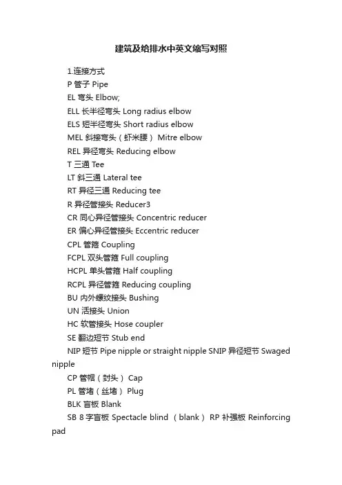
建筑及给排水中英文缩写对照1.连接方式P 管子 PipeEL 弯头 Elbow;ELL 长半径弯头 Long radius elbowELS 短半径弯头 Short radius elbowMEL 斜接弯头(虾米腰) Mitre elbowREL 异径弯头 Reducing elbowT 三通 TeeLT 斜三通 Lateral teeRT 异径三通 Reducing teeR 异径管接头 Reducer3CR 同心异径管接头 Concentric reducerER 偏心异径管接头 Eccentric reducerCPL 管箍 CouplingFCPL 双头管箍 Full couplingHCPL 单头管箍 Half couplingRCPL 异径管箍 Reducing couplingBU 内外螺纹接头 BushingUN 活接头 UnionHC 软管接头 Hose couplerSE 翻边短节 Stub endNIP 短节 Pipe nipple or straight nipple SNIP 异径短节 Swaged nippleCP 管帽(封头) CapPL 管堵(丝堵) PlugBLK 盲板 BlankSB 8字盲板 Spectacle blind (blank) RP 补强板 Reinforcing pad2.法兰PLG 法兰 FlangeWNF 对焊法兰 Welding neck flangeSOF 平焊法兰 Slip-on flangeSWF 承插焊法兰 Socket-welding flangeT 螺纹法兰 Threaded flangeLJ 松套法兰 Lapped joint flangeREDF 异径法兰 Reducing flangeBF 法兰盖(日法兰) Blind flangeFSF 法兰密封面 Flange scaling faceFF 全平面 Flat faceRF 凸台面 Raised faceMFF 凹凸面 Male and female faceLF 凹面 Female faceLM 凸面 Male faceRJ 环连接面 Ring joint faceTG 榫槽面 T ongue and groove faceTF 榫面 T ongue faceGF 槽面 Groove face3.垫片G 垫片 GasketNMG 非金属垫片 Non-metallic gasketAG 石棉垫片 Asbestos gasket RG 橡胶垫片 Rubber gasketTEG 聚四氟乙烯包复垫片 PTFE envelope gasket8 SMG 半金属垫片 Semimetallic gasket,MJG 金属包垫片 Meta-jacket gasketSWG 缠绕式垫片 Spiral wound gasketMG 金属垫片 Metallic gasket.FMG 金属平垫片Flat metallic gasket; SMSG 齿形金属垫片Solid metal serrated gasket LER 透镜式金属环垫 Lens ring gasketOCR 八角形金属环垫 Octagonal ring gasket OVR 椭圆形金属环垫 Oval ring gasketIR/OR 内外定位环 Inner ring and outer ring IR 内定位环 Inner ringOR 外定位环 Outer ring4.紧固件B 螺栓 BoltSB 螺柱 Stud boltNU 螺母 NutTB 花蓝螺母 TurnbuckleWSR 垫圈 WasherSWSR 弹簧垫圈 Spring washer5.阀门GV 闸阀 Gate valveGLV 截止阀 Globe valveCHV 止回阀 Check valveBUV 蝶阀 Butterfly valveBAV 球阀 Ball valvePV 旋塞阀 Plug valve (cock)CV 调节阀 Control valveSV 安全阀 Safety valveRV 减压阀 Pressure reducing valve ST 蒸汽疏水阀 Steam trap PRV 泄压阀 Pressure relief valveBV 呼吸阀 Breather valveNV 针形阀 Needle valveAV 角阀 Angle valveDV 隔膜阀 Diaphragm valveTWV 三通阀 Three-way valveSGV 插板阀 Sluice damper6.管道上的设备SPR 气液分离器 SeparatorFA 阻火器 Flame arresterSR 过滤器 StrainerSRY Y型过滤器 Y-type strainerSRT T型过滤器 T-type strainerSRB 桶式过滤器 Bucket type strainerTSR 临时过滤器 Temporary strainerSIL 消声器 SilencerSG 视镜 Slight glassSC 取样冷却器 Sample coolerDF 排液漏斗 Drain funnelLM 管道混合器 Line mixerRO 限流孔板 Restriction orificeMO 混合孔板 Mixing orificeRD 爆破片(爆破膜) Rupture diskEJ 补偿器 Expansion joint7.隔热、伴热INS 隔热 Thermal insulationH 保温 Hot insulationC 保冷 Cold insulationP 防烫伤隔热 Personnel protection insulation T&I 伴热 Tracing and insulation管道伴热(冷) TracingEST 蒸汽外伴热 External steam tracingIST 蒸汽内伴热 Internal steam tracingSJT 蒸汽夹套伴热 Steam-jacket tracingET 电伴热 Electric tracing8.配管材料和等级M 金属材料 Metallic materialCS 碳钢 Carbon steelCAS,铸钢 Cast steelFS 锻钢 Forged steelAS 合金钢 Alloy steelSS 不锈钢 Stainless steel"AUST SS 奥氏体不锈钢 Austenitic stainless-steel CI 铸铁 Cast ironMI 可锻铸铁 Malleable ironDI 球墨铸铁 Ductile ironAL 铝 AluminumBRS 黄铜 BrassBRZ 青铜 BronzeCU 紫铜 CopperLAS 低合金钢 Low alloy steelFLAS 低合金锻钢 Forged low alloy steelCLAS 低合金铸钢 Cast low alloy steelTHK 壁厚 ThicknessSCH 表号 Schedule numberSTD 标准 StandardXS 加强 Extra strongXXS 特强 Double extra strong9.布局布置CN 建北 Construction northE 东 EastW 西 WestS 南 SouthN 北 NorthH 水平 HorizontalV 竖直、铅直、直立 Vertical1GRD 地坪 GroundUG 地下 UndergroundBL 装置边界线 Battery limit lineESEW 事故沐浴洗眼器 Emergency shower and eye washer HS 软管站 Hose stationML 接续分界线 Match linePS 管道支架(管架) Piping support;PR 管桥 Pipe rackSTRU 构架(构筑物) StructureBLDG 建筑物 BuildingPD 清扫设施 Purge devicePT 池 PitSHLT 棚 ShelterCOFF 围堰 CofferdamFL 楼板 FloorPF 平台 Platform10.尺寸标注EL 标高 ElevationBOP 管底 Bottom of pipeCOP 管中心 Center of pipeTOP 管顶 Top of pipeFOB 底平 Flat on bottomFOT 顶平 Flat on topCL (屯)中心线 Center lineTL 切线 Tangent lineSYM 对称的 SymmetricalBOS 支架底 Bottom of supportTOS 支架顶 Top of supportCL 净距(净空) ClearanceCTC 中心至中心 Center to centerCTF 中心至面 Center to faceCTE 中心至端部 Center to endETE 端到端 End to endFEF 法兰端面 Flange and faceFTF 面到面 Face to faceD 直径 DiameterDN 公称直径 Nominal diameterID 内径 Inside diameter.OD 外径 Outside diameterDIM 尺寸 DimensionMAX 最大 MaximumMIN 最小 MinimumAVG 平均 AverageAPP 约、近似 ApproximatePT.EL 点标高 Point elevation11.图表PFD 工艺流程图 Process flow diagramPID 管道和仪表流程图 Piping & instrument diagram COD 接续图 Continued on drawingDTL 详图 DetailSPDWG(ISODWG)管段图 Spool drawing(each line isometric drawing)DWGNO 图号Drawing numberDWGI 所在图号 Drawing identificationLOW 材料表 List of materialMTO 汇料 Material take-offAPPX 附录 AppendixJOB. No. 工号 Job NumberBEDD 基础工程设计数据 Basic engineering design data DEDD 详细工程设计数据 Detail engineering design data REV. No. 修改号Recision numberREF DWG 参考图 Reference drawingSC 采样接口 Sample connection12.操作方式及工作参数AUT 自动 AutomaticML 手动 Manual controlCHOP 链条操作 Chain operatedCSC 铅封关 Car seal closeCSO 铅封开 Car seal openLC 锁闭 Lock closedLO 锁开 Lock openNC 正常关 Normally closeNO 正常开 Normally openATM 大气压 AtmospherePN 公称压力 Nominal pressurePA 绝压 Absolute pressurePG 表压 Gage pressureT 温度 TemperatureP 压力 Pressure13施工W 焊接 WeldingAW 电弧焊 Arc weldingGSAW 气体保护电弧焊 Gas shielded-acr welding EFW 电熔焊 Elecric fusion weldingERW 电阻焊 Electric Resistance weldingGW 气焊 Gas weldingLW 搭接焊 Lap weldingBW 对焊 Butt weldingTW 定位焊 Tack weldingSW 承插焊 Socket weldingCW 连续焊 Continuous weldingSEW 密封焊 Seal weldingSFG 堆焊 SurfacingFW 现场焊接 Field weldingHT 热处理 Heat treatmentPH 预热 PreheatingSR 应力消除 Stress reliefPWHT 焊后热处理 Post weld heat treatmentEIT 检查、探伤和实验 Examination, inspection & testing VE 外观检查 Visual examinationUI (UT)超声探伤 Ultrasonic inspection (test)RI (RT)射线探伤Radiographic inspection (test)MPI (MT)磁粉探伤 Magnetic particle inspection (test)LPI (PT)液体渗透检验 Liquid penetrate inspection (test)HADT 硬度实验Hardness testingHYDT 水压实验Hydraulic testing PNET 气压实验Pneumatic testingCE 焊条 Covered electrodeWW 焊丝 Welding wireASSY 装配、组合 AssemblyF 现场 FieldF/F 现场制造 Field fabricatedSF 现场决定 Suit in fieldCSP 冷紧 Cold springBCT 螺栓冷紧 Bolt cold tighteningBHY 螺栓热紧 Bolt hot tighteningCO 清洗口 Clean outANNY 退火 AnnealedPE 平端面 Plain endBE 坡口端 Bevelled endTHR 螺纹 ThreadHB 布氏硬度 Brinell hardnessRC 洛氏硬度 Rockwell hardness14.其他FDN 基础 FoundationINF 信息(资料) InformationREF 参考 Reference'REV 修改 RevisionSEQ 序号(顺序) SequenceW/E 设备带来 With equipmentW/I 仪表带来 With instrumentCM 色标 Colour markCA 腐蚀裕度 Corrosion allowanceUTL 公用系统 UtilityUC 公用工程接头 Utility connectionQTY 数量 QuantityWT 重量 WeightMHR 工时 Man hourBC 螺栓分布圆 Bolt circleHP 高点 High pointLP 低点 Low pointSUC 吸入(口) SuctionDIS 排出(口) DischargeSO 蒸气吹扫(口) Steam outNPT 美国标准锥管螺纹National standard taper pipe thread NPS 美国标准直管螺纹 National standard straight pipe threadDR 排液 DrainVT 放气 VentRTG (压力)等级 RatingCL 等级 Class SMLS 无缝 Seamless。
《给水排水专业英语》Lesson 1specific yield [spə'sifik] [ji:ld] 单位产水量mass curve 累积曲线capital investment 投资recurring natural event ['nætʃərəl] 重现历史事件subterranean [sʌbtə'reiniən] 地下的groundwater 地下水surface water 地表水tap [tæp]开关、龙头;在…上开空(导出液体)swampland ['swɔmplænd] n. 沼泽地;沼泽地带capillary [kə'piləri] n. 毛细管adj. 毛状的,毛细管的hygro- [词头] 湿(气),液体hygroscopic [,haigrəu'skɔpik] adj. 易湿的,吸湿的hygroscopic moisture 吸湿水stratum ['streitəm] n. [地质学]地层,[生物学](组织的)层aquifer ['ækwəfə] ['ækwifə] n.含水层,地下蓄水层saturation [,sætʃə'reiʃən] n.饱和(状态),浸润,浸透,饱和度hydrostatic [,haidrəu'stætik] adj. 静水力学的, 流体静力学的hydrostatic pressure 静水压力water table 1. 地下水位,地下水面,潜水面2. 【建筑学】泻水台;承雨线脚;飞檐;马路边沟[亦作water-table]Phreatic surface [fri(:)'ætik]地下水(静止)水位,浅层地下水面Superficial [sju:pə'fiʃəl] adj. 表面的,表观的,浅薄的Porosity [pɔ:'rɔsiti] n. 多孔性,有孔性,孔隙率Unconfined ['ʌnkən'faind] adj. 无约束的,无限制的Permeability [,pə:miə'biliti] n. 弥漫, 渗透, 渗透性Permeameter [pə:mi'æmitə] n.渗透仪,渗透性试验仪)Clay [klei] n. 粘土,泥土gravel ['ɡrævəl]n.[总称]砾,沙砾,小石;砾石cone of depression [kəun] 下降漏斗, [水文学]下降锥体drawdown ['drɔ:daun] n. 水位下降(降落,消耗,减少)integrate ['intigreit] 【数学】作积分运算;求积分observation well [,əbzə:'veiʃən] 观测井,观测孔extraction [ik'strækʃən] n. 抽出,取出,提取(法),萃取(法)derivation [deri'veiʃən] n. 1. 导出,引(伸)出,来历,出处,得出,得到;诱导,推论,推理;溯源【数学】1) (定理的)求导,推导2) 微商,微分,导数【语言】词源,衍生deplete [di'pli:t] v. 耗尽, 使...衰竭refuse [ri'fju:z] n. 废物,垃圾vt. 拒绝,谢绝dump [dʌmp] n. 垃圾场,垃圾堆,堆存处vt. 倾卸,倾倒(垃圾)unconfined aquifer 潜水含水层,非承压含水层,无压含水层confined aquifer 自流含水层,承压含水层homogeneous [,hɔməu'dʒi:njəs] adj. 同类的,相似的,均匀的,均相的;同种类的,同性质的;相同特征的Aquaclude 不透水层,难渗透水的地层Offset ['ɔ:fset] n.偏移量抵销,弥补,分支,胶印,平版印刷,支管,乙字管Vt. 弥补,抵销,用平版印刷vi. 偏移,形成分支sophisticated [sə'fistikeitid] adj. 复杂的,需要专门技术的;诡辩的,久经世故的equilibrium [,i:kwi'libriəm] n. 平衡,均衡Water Supply(给水工程)A supply of water is critical to the survival of life, as we know it.(众所周知,水对生命的生存至关重要。
给水排水工程通用术语给水排水工程的通用术语1、给水工程water supply engineering 原水的取集和处理以及成品水输配的工程。
2、排水工程sewerage ,wastewater engineering 收集、输送、处理和处置废水的工程。
3、给水系统water supply system 给水的取水、输水、水质处理和配水等设施以一定方式组合成的总体。
4、排水系统sewerage system 排水的收集、输送、水质处理和排放等设施以一定方式组合成的总体。
5、给水水源water source 给水工程所取用的原水水体。
6、原水raw water 由水源地取来的原料水。
7、地表水surface water 存在于地壳表面,暴露于大气的水。
8、地下水ground water 存在于地壳岩石裂缝或工壤空隙中的水。
9、苦咸水(碱性水) brackish water ,alkaline water 碱度大于硬度的水,并含大量中性盐,PH值大于7。
10、淡水fresh water 含盐量小于500mg/L的水。
11、冷却水cooling water 用以降低被冷却对象温度的水。
12、废水wastewater 居民活动过程中排出的水及径流雨水的总称。
它包括生活污水、工业废水和初雨径流以及流入排水管渠的其它水。
13、污水sewage ,wastewater 受一定污染的来自生活和生产的排出水。
14、用水量water consumption 用水对象实际使用的水量。
15、污水量wastewater flow ,sewage flow 排水对象排入污水系统的水量。
16、用水定额water flow norm 对不同的排水对象,在一定时期内制订相对合理的单位排水量的数值。
17、排水定额wastewater flow norm 对不同的排水对象,在一定时期内制订相对合理的单位排水量的数值。
18、水质water quality 在给水排水工程中,水的物理、化学、生物学等方面的性质。
建筑给水排水及采暖工程施工术语解释2.0.1 给水系统 water supply system通过管道及辅助设备,按照建筑物和用户的生产、生活和消防的需要,有组织的输送到用水地点的网络。
2.0.2 排水系统 drainage system通过管道及辅助设备,把屋面雨水及生活和生产过程所产生的污水、废水及时排放出去的网络。
2.0.3 热水供应系统 hot water supply system为满足人们在生活和生产过程中对水温的某些特定要求而由管道及辅助设备组成的输送热水的网络。
2.0.4 卫生器具 sanitary fixtues用来满足人们日常生活中各种已生要求、收集和排放生活及生产中的污水、废水的设备。
2.0.5 给水配件 water supply fittings在给水和热水供应系统中,用以调节、分配水量和水压,关断和改变水流方向的各种管件、阀门和水嘴的统称。
2.0.6 建筑中水系统 intemediate water system of building以建筑物的冷却水、沐浴排水、盥洗排水、洗衣排水等为水源,经过物理、化学方法的工艺处理,用于厕所冲洗便器、绿化、洗车、道路浇洒、空调冷却及水景等的供水系统为建筑中水系统。
2.0.7 辅助设备 wuxiliaris建筑给水、排水及采暖系统中,为满足用户的各种使用功能和提高运行质量而设置的各种设备。
2.0.8 试验压力 text presssure管道、容器或设备进行耐压强度和气密性试验规定所要达到的压力。
2.0.9 额定工作压力 rated pressure指锅炉及压力容器出厂时所标定的最高允许工作压力。
2.0.10 管道配件 pipe fittings管道与管道或管道与设备连接用的各种零、配件的统称。
2.0.11 固定支架 fixed trestle限制管道在支撑点处发生轴向位移的管道支架。
2.0.12 活动支架 movable trestle允许管道在支撑点处发生轴向位移的管道支架。
建筑英语中给排水资料收集标签/分类:建筑类翻译词汇园建筑英语《给水排水设计基本术语标准》编号:GBJ 125-891.1给水排水设计基本术语1.2给水排水工程的通用术语及其含义应符合下列规定:给水工程water supply engineering 原水的取集和处理以及成品水输配的工程。
排水工程sewerage,wasterwater engineering 收集、输送、处理和处置废水的工程。
给水工程water supply system 给水的取水、输水、水质处理和配水等设施以一定的方式组合成的总体。
排水系统sewerage system 排水的收集、输送、水质的处理和排放等设施以一定方式组合成的总体。
给水水源water source 给水工程所取用的原水水体。
原水raw water 由水源地取来的原料水。
地表水surface water 存在于地壳表面,暴露于大气的水。
地下水ground water 存在于地壳岩石裂缝或土壤空隙中的水。
苦咸水(碱性水)brackish water,alkaline water 碱度大于硬度的水,并含大量中性盐,ph值大于7。
淡水fresh water 含盐量小于500mg /L的水。
冷却水cooling water 用以降低被冷却对象温度的水。
废水wastewater 居民活动过程中排出的水及径流雨水的总称。
它包括污水、工业废水和初雨径流入排水管渠的其它水。
污水sewage,wastewater 受一定污染的来自生活和生产的排出水。
用水量water consumption 用水对象实际使用的水量。
供水量output 向用水对象实际使用的水量。
污水量wastewater flow,sewage flow 排水对象排入污水系统的水量。
用水定额water consumption norm 对不同的用水对象,在一定时期内制订相对合理的单位用水量的数值。
排水定额wastewater flow norm 对不同的排水对象,在一定时期内制订相对合理的单位排水量的数额。
建筑给水排水设计规范的术语有哪些?-工程建筑给水排水设计规范的术语有哪些?2.1 术语2.1.4 最大时用水量 maximum hourly water consumption最高日最大用水时段内的小时用水量,。
2.1.4A平均时用水量 average hourly water consumption最高日用水时段内的平均小时用水量。
2.1.7A倒流防止器 backflow prevent一种采用止回部件组成的可防止给水管道水流倒流的装置。
2.1.7B真空破坏器 vacuum breakers一种可导入大气压消除给水管道内水流因虹吸而倒流的装置2.1.13A 叠压供水 additive pressure water supply利用室外给水管网余压直接抽水再增压的二次供水方式。
2.1.17(此条删除)2.1.18(此条删除)2.1.32自灌self-priming水泵启动时水靠重力充入泵体的引水方式。
2.1.53A自循环通气 auto circulation venting通气立管在顶端、层间和排水立管相连,在底端与排出管连接,排水时在管道内产生的正负压通过连接的通气管道迂回补气而达到平衡的通气方式。
2.1.54A真空排水 vacuum drain利用真空设备使排水管道内产生一定真空度,利用空气输送介质的排水方式。
2.1.54B 同层排水 same-floor drainage排水横支管布置在排水层或室外,器具排水管不穿楼层的排水方式。
2.1.55A埋设深度 buried depth埋地排水管道内底至地表面的垂直距离。
2.1.58A隔油器grease interceptor分隔、拦集生活废水中油脂的装置。
2.1.61中水 reclaimed water各种排水经适当处理达到规定的水质标准后回用的水。
2.1.66暴雨强度 rainfall intensity单位时间内的降雨量。
2.1.68降雨历时 duration of rainfall降雨过程中的任意连续时段。
建筑给水排水基本术语中英对照翻译Building Water Supply and Drainage Terms Translation建筑给水排水基本术语中英对照翻译IntroductionBuilding water supply and drainage is an essential part of the construction process. Understanding the terminology involved is critical to ensure proper installation and safety. This article will provide a English to Chinese translation of some basic building water supply and drainage terminology for those involved in the construction industry or those looking to improve their language skills.术语Terminology1. Main Water Line: 主供水管2. Supply Line: 供水管道3. Drain Line: 排水管道4. Sewer Line: 污水管道5. Valve: 阀门6. Shut-off Valve: 切断阀门7. Pressure Regulator: 压力调节阀8. Pressure Relief Valve: 减压阀9. Backflow Preventer: 防回流阀10. Floor Drain: 地漏11. Trap: 管道弯头12. Trap Seal: 弯头水封13. Vent: 排气管14. Cleanout: 清洁口15. Water Meter: 水表16. Water Softener: 软水器17. Water Heater: 热水器18. Waste Water: 废水19. Grey Water: 灰水20. Black Water: 黑水Translation and Explanation1. Main Water Line: The main water line refers to the water supply line that brings water from the city or town's main water supply to the building.主供水管:主供水管道是指将城市或镇的主要供水管带水进入建筑物的供水管道。
给排水常用专有名词中英文对照Introduction给排水工程是指在建筑物内设置一定的设施,以便实现供水、排水、雨水排放和污水处理等功能的工程。
在给排水领域,有很多专有名词,这些名词在建筑设计与施工过程中至关重要。
本文将介绍给排水常用专有名词的中英文对照,以帮助读者更好地了解这些名词的含义。
Pipes1. 水管Water Pipe水管是用来输送清洁水的管道。
水管通常使用聚乙烯、聚氯乙烯、水泥、铸铁等材料制成。
其直径有大小之分,根据工程需要进行选择。
2. 排水管Drain Pipe排水管是用来排放生活污水和雨水的管道。
排水管通常使用聚氯乙烯、铸铁、水泥、预制混凝土等材料制成,其直径大小也有不同规格。
3. 初次排污管Primary Drain Pipe初次排污管通常指从家庭、工厂、商场等的“首次”排污管。
这类管道的直径通常比较大,材料较粗,以便排放大量的污水。
4. 无压排水管Non-pressure Drain Pipe无压排水管是一种不需要压力的排水管道。
这种管道通常建立在建筑物的低处,以便将污水顺利排放出去。
5. 垂直排水管Vertical Drain Pipe垂直排水管是指垂直于地面的排水管道,主要负责将生活污水从建筑物内部排放出去。
Fittings1. 水管接头Water Pipe Joint水管接头通常用于连接水管,其形状很多,可以根据实际需要选择不同类型的接头。
例如,有夹紧接头、螺旋接头等。
2. 排水管接头Drain Pipe Joint排水管接头是用来连接排水管的管道连接件。
这类接头通常是由橡胶、铸铁等材料制成。
3. 弯头Elbow弯头是一种用于改变管道方向的管道连接件,通常由铸铁、钢、铜等材料制成。
4. 管道三通Tee管道三通是一种管道连接件,通常用于将三个管道连接在一起。
这种连接件可以分为不等口径三通和等口径三通。
Valves1. 关闭阀门Stop Valve关闭阀门是一种管道阀门,通常用于中止管道内的水流,以便对管道进行维修或更换。
建筑给水排水基本术语中英对照翻译(中德工程建筑设施智能技术093132 张伟)1、给水工程water supply engineering 原水的取集和处理以及成品水输配的工程。
2、排水工程sewerage ,wastewater engineering 收集、输送、处理和处置废水的工程。
3、给水系统water supply system 给水的取水、输水、水质处理和配水等设施以一定方式组合成的总体。
4、排水系统sewerage system 排水的收集、输送、水质处理和排放等设施以一定方式组合成的总体。
5、给水水源water source 给水工程所取用的原水水体。
6、原水raw water 由水源地取来的原料水。
7、地表水surface water 存在于地壳表面,暴露于大气的水。
8、地下水ground water 存在于地壳岩石裂缝或土壤空隙中的水。
9、苦咸水(碱性水) brackish water ,alkaline water 碱度大于硬度的水,并含大量中性盐,PH值大于7。
10、淡水fresh water 含盐量小于500mg/L的水。
11、冷却水cooling water 用以降低被冷却对象温度的水。
12、废水wastewater 居民活动过程中排出的水及径流雨水的总称。
它包括生活污水、工业废水和初雨径流以及流入排水管渠的其它水。
13、污水sewage ,wastewater 受一定污染的来自生活和生产的排出水。
14、用水量water consumption 用水对象实际使用的水量。
15、污水量wastewater flow ,sewage flow 排水对象排入污水系统的水量。
16、用水定额water flow norm 对不同的排水对象,在一定时期内制订相对合理的单位排水量的数值。
17、排水定额wastewater flow norm 对不同的排水对象,在一定时期内制订相对合理的单位排水量的数值。
建筑给水排水基本术语中英对照翻译(中德工程建筑设施智能技术093132 张伟)1、给水工程water supply engineering 原水取集和处理以及成品水输配工程。
2、排水工程sewerage ,wastewater engineering 收集、输送、处理和处置废水工程。
3、给水系统water supply system 给水取水、输水、水质处理和配水等设施以一定方式组合成总体。
4、排水系统sewerage system 排水收集、输送、水质处理和排放等设施以一定方式组合成总体。
5、给水水源water source 给水工程所取用原水水体。
6、原水raw water 由水源地取来原料水。
7、地表水surface water 存在于地壳表面,暴露于大气水。
8、地下水ground water 存在于地壳岩石裂缝或土壤空隙中水。
9、苦咸水(碱性水) brackish water ,alkaline water 碱度大于硬度水,并含大量中性盐,PH值大于7。
10、淡水fresh water 含盐量小于500mg/L水。
11、冷却水cooling water 用以降低被冷却对象温度水。
12、废水wastewater 居民活动过程中排出水及径流雨水总称。
它包括生活污水、工业废水和初雨径流以及流入排水管渠其它水。
13、污水sewage ,wastewater 受一定污染来自生活和生产排出水。
14、用水量water consumption 用水对象实际使用水量。
15、污水量wastewater flow ,sewage flow 排水对象排入污水系统水量。
16、用水定额water flow norm 对不同排水对象,在一定时期内制订相对合理单位排水量数值。
17、排水定额wastewater flow norm 对不同排水对象,在一定时期内制订相对合理单位排水量数值。
18、水质water quality 在给水排水工程中,水物理、化学、生物学等方面性质。
19、渠道channel ,conduit 天然、人工开凿、整治或砌筑输水通道。
20、泵站pumping house 设置水泵机组、电气设备和管道、闸阀等房屋。
21、泵站pumping station 泵房及其配套设施总称。
22、给水处理water treatment 对不符合对象水质要求水。
进行水质改善过程。
23、污水处理sewage treatment ,wastewater treatment 为使污水达到排水某一水体或再次使用水质要求,对其进行净化过程。
24、废水处理wastewater disposal 对废水最终安排。
一般将废水排入地表水体、排放土地和再次使用等。
25、格栅bar screen 一种栅条形隔污设备,用以拦截水中较大尺寸漂浮物或其他杂物。
26、曝气aeration 水与气体接触,进行溶氧或散除水中溶解性气体和挥发性物质过程。
27、沉淀sedimentation 利用重力沉降作用去除水中杂物过程。
28、澄清clarification 通过与高浓度沉渣层接触而去除水中杂物过程。
29、过滤filtration 借助粒状材料或多孔介质截除水中质物过程。
30、离子交换法ion exchange 采用离子交换剂去除水中某些盐类离子过程。
31、氯化chlorination 在水中投氯或含氯氧化物方法消灭病原体过程。
32、余氯residual chlorine 水中投氯,经一定时间接触后,在水中余留游离性氯和结合性氯总和。
33、游离性余氯free residual chlorine 水中以次氯酸和次氯酸盐形态存在余氯。
34、结合性余氯combinative residual chlorine 水中以二氯胺和一氯胺形态存在余氯。
35、污泥sludge 在水处理过程中产生,以及排水管渠中沉积固体与水混合物或胶体物。
36、污泥处理sludge treatment 对污泥最终安排。
一般将污泥作农肥、制作建筑材料、填埋和投弃等。
37、水头损失head loss 水流通过管渠、设备和构筑物等所引起能量消耗。
38、直流水系统once through system 水经过一次使用后即行排放或处理后排放给水系统。
39、复用水系统water reuse system 水经重复利用后再行排放或处理后排放给水系统。
40、循环水系统recirculation system 水经使用后不予排放而循环利用或处理后循环利用给水系统。
41、生活用水domestic water 人类日常生活所需用水。
42、生产用水process water 生产过程所需用水。
43、消防用水fire demand 扑灭火灾所需用水。
44、浇洒道路用水street flushing demand ,road watering 对城镇道路进行保养、清洗、降温和消尘等所需用水。
45、绿化用水green belt sprinkling ,green plot sprinkling 对市政绿地等所需用水。
46、管井deep well ,drilled well 井管从地面打到含水层,抽取地下水井。
47、管井滤水管deep well screen 设置在管井动水位以下,用以从含水层中集水有缝隙或孔隙管段。
48、管井沉淀管grit compartment 位于管井最下部,用以容纳进入井内沙粒和从水中析出沉淀物管段。
49、大口井dug well ,open well 由人工开挖或沉井法施工,设置井筒,以截取浅层地下水构筑物。
50、井群batter of wells 数个井组成群体。
51、渗渠infiltration gallery 壁上开孔,以集取浅层地下水水平管渠。
52、地下水取水构筑物反滤层inverted layer 在大口井或渗渠进水处铺设粒径沿水流方向由细到粗级配砾层(简称反滤层)53、泉室spring chamber 集取泉水构筑物。
54、进水间intake chamber 连接取水管与吸水井、内设格栅或格网构筑物。
55、格网screen 一种网状用以拦截水中较大尺寸漂浮物、水生动物或其他污染物拦污设备。
其网眼尺寸较格栅为小。
56、吸水井suction well 为水泵吸水管专门设置构筑物。
57、净水构筑物purification structure 以去除水中悬浮固体和胶体杂质等为主要目构筑物总称。
58、投药chemical dosing 为进行水处理而向水中加一定剂量化学药剂过程。
59、混合mixing 使投入药剂迅速均匀地扩散于被处理水中以创造良好凝聚反应条件过程。
60、凝聚coagulation 为了消除胶体颗粒间排斥力或破坏其亲水性,使颗粒易于相互接触而吸附过程。
61、絮凝flocculation A、完成凝聚胶体在一定外力扰动下相互碰撞、聚集以形成较大絮状颗粒过程。
曾用名反应。
B、高分子絮凝剂在悬浮固体和胶体杂质之间吸附架桥过程。
62、自然沉淀plain sedimentation 不加注任何凝聚剂沉淀过程。
63、凝聚沉淀coagulation sedimentation 加注凝聚剂沉淀过程。
64、凝聚剂coagulant 在凝聚过程中所投加药剂统称。
65、助凝剂coagulant aid 在水沉淀、澄清过程中,为改善絮凝效果,另设加辅助药剂。
66、药剂固定储备量standby reserve 为考虑非正常原因导致药剂供应中断,而在药剂仓库内设置在一般情况下不准动用储备量。
简称固定储备量。
67、药剂周转储备量current reserve 考虑药剂消耗与供应时间之间差异所需储备量。
简称周转储备量。
68、沉沙池(沉砂池)desilting basin ,grit chamber 去除水中自重很大、能自然沉降较大粒径沙粒或杂粒水池。
69、预沉池pre-sedimentation tank 原水中泥沙颗粒较大或浓度较高时,在进行凝聚沉淀处理前设置沉淀池。
70、平流沉淀池horizontal flow sedimentation tank 水沿水平方向流动沉淀池。
71、异向流斜管(或斜板)沉淀池tube(plate)settler 池内设置斜管(或斜板),水自下而上经斜管(或斜板)进行沉淀,沉泥沿斜管(或斜板)向下滑动沉淀池。
72、同向流斜板沉淀池lamella 池内设置斜板,沉淀过程在斜板内进行,水流与沉泥均沿斜板向下流动沉淀池。
73、机械搅拌澄清池accelerator 利用机械使水提升和搅拌,促使泥渣循环,并使原水中固体杂质与己形成泥渣接触絮凝而分离沉淀水池。
74、水力循环澄清池circulator clarifier 利用水力使水提升,促使泥渣循环,并使原水中固体杂质与己形成泥渣接触絮凝而分离沉淀水池。
75、脉冲澄清池pulsator 悬浮层不断产生固周期性压缩和膨胀,促使原水中固体杂质与己形成泥渣进行接触凝聚页分离沉淀水池。
76、悬浮澄清池sludge blanket clarifier 加药后原水由上通过处于悬浮状态泥渣层,使水中杂质与泥渣悬浮层颗粒碰撞凝聚而分离沉淀水池。
77、液面负荷surface load 在沉淀池、澄清池等沉淀构筑物净化部分中,单位液(水)面积所负担出水流量。
其计量单位通常以m3/(m2.h)表示。
78、气浮池floatation tank 运用絮凝和浮选原理使液体中杂质分离上浮而去除池子。
79、气浮溶气罐dissolved air vessel 在气浮工艺中,水与空气在有压条件下相互溶合密闭容器。
简称溶气罐。
80、清水池clear-water reservoir 为贮存水厂中净化后清水,以调节水厂制水量与供水量之间差额,并为满足加氯接触时间而设置水池。
81、自灌充水将离心泵泵顶设于最低吸水位标高以下,启动时水靠重力充入泵体引水方式。
82、转输流量水厂向设在配水管网中调节构筑物输送水量。
83、配水管网distribution system ,pipe system 将水送到分配管网以至用户管系。
84、环状管网pipe network 配水管网一种置形式,管道纵横相互接通,形成环状。
85、枝状管网branch system 配水管网一种布置形式,干管和支管分明,形成树枝状。
86、水管支墩buttress ,anchorage 为防止由管内水压引起水管配件接头移位而造成漏水,需在水管干线适当部位砌筑墩座。
简称支墩。
87、排水制度sewer system 在一个地区内收集和输送废水方式。
它有合流制和分流制两种基本方式。
88、合流制combined system 用同一种管渠分别收集和输送废水排水方式。
89、分流制separate system 用不同管渠分别收集和输送各种污水、雨水和生产废水排水方式。