Progetto di Laboratorio per il corso di Programmazione in Rete e Laboratorio
- 格式:pdf
- 大小:402.18 KB
- 文档页数:22

申请都灵理工大学留学材料及流程一览都灵理工大学是意大利成立最早的国立理工科大学,建于1906年,作为历史悠久的欧洲名校,都灵理工大学在世界范围内的声誉和威望都较高。
接下来为大家介绍申请都灵理工大学留学材料及流程。
1.护照2. 个人简历3. 学位证书如果还没毕业,则使用在读证明代替。
4. 毕业证书如果还没毕业,则使用在读证明代替。
5. 在读证明去学校教务处开,需要盖章(已毕业的不需要)。
6. 成绩单每一页都需要盖章,最好使用有学校名称的抬头纸。
7. 语言要求意大利语授课:意大利语B1+雅思5.5;英语授课:雅思5.5;意大利语+英语授课:意大利语B1+雅思5.5。
8. 推荐信最好有2封,一封出自本校的系主任或校长等,一封出自业界,我们的推荐信都是自己写,然后找大佬签字的,如果有大佬愿意亲自为你写就更好啦。
9. 课程描述每门课+概述,翻译成英语/意大利语。
10. 获奖证明/实习证明11.作品集建筑-城市建设,建筑-可持续建设,建筑-遗产修复与评估,系统设计必须有。
1、首先我们进入都灵理工大学的官网,进入官网后进入网申页面。
2、在网页上注册账号以后都理会给你的邮箱发一封邮件,确认后,补充自己的资料,就可以用注册的账号进行登录啦。
3、研究生可申请两个专业,接着按照要求上传所有的材料(材料清单见下文,记住所有材料需要翻译成英语或者意大利语,并附上中文原件),交完20欧元的考试注册费,就等着好消息吧。
(一)本科申请要求1、学生须持有高中毕业证书或同等学历证书,“马可波罗计划”高考成绩在400分(满分750)及以上即可。
2、语言要求意大利语:B1;英语(英语授课课程):雅思5.5。
3、入学考试1)意大利建筑考试意大利建筑类专业的考试是全国统考的,因此所有学校都是同一天的同一个时间举行考试,建筑统考需要在Universitaly上进行注册,然后再在都理官网进行注册。
2)TIL- Test in LAIB报名除建筑以外所有专业的学生(包括工程类、设计与视觉传达、环境与土地规划)都必须要参加并通过这个考试,才有资格注册都灵理工大学(二)研究生申请要求1、持有本科阶段学士学位证书、大学成绩单、大学课程描述、高中毕业证书或同等学历证书,有高考成绩。
通信11 S7-1200 可实现 CPU 与编程设备、HMI 和其它 CPU 之间的多种通信。
警告PROFINETPROFINET 用于使用用户程序通过以太网与其它通信伙伴交换数据:●在 S7-1200 中,PROFINET 支持 16 个最多具有 256 个子模块的 IO设备,PROFIBUS 允许使用 3 个独立的 PROFIBUS DP 主站,每个 DP 主站支持 32个从站,每个 DP 主站最多具有 512 个模块。
●S7 通信●用户数据报协议 (UDP)●ISO on TCP (RFC 1006)●传输控制协议 (TCP)通信PROFINET IO 控制器作为采用 PROFINET IO 的 IO 控制器,CPU 可与本地 PN 网络上或通过 PN/PN耦合器(连接器)连接的最多 PROFIBUS和PROFIBUSPROFIBUS 用于使用用户程序通过 PROFIBUS 网络与其它通信伙伴交换数据:●借助 CM 1242-5,CPU 作为 PROFIBUS DP 从站运行。
●借助 CM 1243-5,CPU 作为 1 类 PROFIBUS DP 主站运行。
●PROFIBUS DP 从站、PROFIBUS DP 主站和 AS-i(左侧 3 个通信模块)以及PROFINET 均采用单独的通信网络,不会相互制约。
AS-i通过 S7-1200 CM 1243-2 AS-i 主站可将 AS-i 网络连接到 S7-1200 CPU。
CPU 至 CPU S7 通信您可以创建与伙伴站的通信连接并使用 GET 和 PUT 指令与 S7 CPU 进行通信。
TeleService 通信在通过 GPRS 的 TeleService 中,安装了 STEP 7 的工程师站通过 GSM 网络 Internet和与具有 CP 1242-7 的 SIMATIC S7-1200 站进行通信。
该连接通过用作中介并连接到Internet 的远程控制服务器运行。


意大利大学预注册2008-2009学年在2008-2009学年意大利大学预注册日期正式公布前,意大利驻华大使馆要求申请人准备好以下文件材料:1)申请预注册普通大学本科课程a)经中国外交部和意大利驻华使馆领事处双认证的高中毕业证书(需翻译成意大利语);b)向教育部学位与研究生教育发展中心()申请办理以下证明:高考成绩证明高中会考合格证(对于实行高中会考的省份)中心会直接将证明文件递送至意大利使馆(申请人只需保留付款收据);c)从以下四个意大利外交部认可的语言培训机构获得的A2或A2以上等级的语言水平证书:佩鲁贾外国人大学,锡耶纳外国人大学,罗马第三大学,但丁学院;d)个人护照。
请注意:申请预注册的学生的高考成绩不得低于380分(满分750分);申请学生须提交由意大利外交部认可的语言培训机构发放的A2或A2以上等级的语言水平证书:意大利驻华使馆保留对申请人的语言水平进行考核的权利;高三在读的申请人,须先提交c)和d)中所述材料,在高考及会考考试后尽快提交a)和b)中所述文件以完成预注册程序;预注册申请的最终结果将于8月下旬由意大利大学通知意大利驻华使馆。
只有在收到大学的预录取通知书后,意大利驻华大使馆方可发放签证。
2)申请预注册艺术类院校本科课程a)经中国外交部和意大利驻华使馆领事处双认证的高中毕业证书(需翻译成意大利语);b)向教育部学位与研究生教育发展中心()申请办理以下证明:高考成绩证明;在艺术类院校进行的专业考试证明(如表演、舞蹈、声乐、乐器演奏等);高中会考合格证(对于实行高中会考的省份);中心会直接将证明文件递送至意大利使馆(申请人只需保留付款收据);c)从以下四个意大利外交部认可的语言培训机构获得的A2或A2以上等级的语言水平证书:佩鲁贾外国人大学,锡耶纳外国人大学,罗马第三大学,但丁学院;d)个人护照。
请注意:申请学生须提交由意大利外交部认可的语言培训机构发放的A2或A2以上等级的语言水平证书:意大利驻华使馆保留对申请人的语言水平进行考核的权利;高三在读的申请人,须先提交c)和d)中所述材料,在高考及会考考试后尽快提交a)和b)中所述文件以完成预注册程序;预注册申请的最终结果将于8月下旬由意大利大学通知意大利驻华使馆。
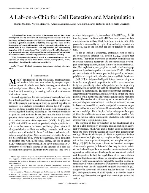
A Lab-on-a-Chip for Cell Detection and ManipulationGianni Medoro,NicolóManaresi,Andrea Leonardi,Luigi Altomare,Marco Tartagni,and Roberto GuerrieriAbstract—This paper presents a lab-on-a-chip for electronic manipulation and detection of microorganisms based on the use of closed dielectrophoretic(DEP)cages combined with impedance sensing.A printed circuit board(PCB)prototype has been used to trap,concentrate,and quantify polystyrene micro-beads in agree-ment with CAD simulations.The experiment was successfully repeated with S.cerevisiae.The results prove the effectiveness of the approach for particle manipulation and detection without the need for external optical components nor chemical labeling.With the proposed approach,particle concentration may be in-creased on-chip of more than three orders of magnitude,corre-spondingly boosting the detection sensitivity.Index Terms—Dielectrophoresis,impedance sensing,lab-on-a-chip.I.I NTRODUCTIONM ANY applications in the biological,pharmaceutical, and medical fields are characterized by complex exper-imental protocols which need both microorganism detection and manipulation.Hence,labs-on-a-chip need to integrate functions such as sensing,processing,and actuation to increase their effectiveness.Several approaches for microorganism manipulation have been developed based on dielectrophoresis.Dielectrophoresis [1]is the physical phenomenon whereby neutral particles,in response to a spatially nonuniform electric field,experi-ence a net force directed toward locations with increasing or decreasing field intensity according to the physical properties of particles and medium.In the first case,the force is called positive dielectrophoresis(pDEP)while in the second case it is called negative dielectrophoresis(nDEP).In[2],both pDEP and nDEP are used to precisely displace cells in a microchamber formed between two facing glass chips with elongated electrodes.However,cells get in contact with device surfaces and tend to stick to them.A solution is to levitate cells while manipulating them.Since maxima of the electric field can not be established away from the electrodes,stable levitation is possible only with nDEP force.Hence,the use of closed nDEP cages has been proposed.In[3],three-dimensional(3-D) structures of electrodes located at the vertexes of a cube are used for such a purpose.The main drawback is that fluid flow isManuscript received May20,2002;revised December6,2002.This work was supported by EC under Contract IST-2001-32437.The associate editor co-ordinating the review of this paper and approving it for publication was Prof. Jan Soderkvist.G.Medoro and N.Manaresi are with Silicon Biosystems,Bologna, Italy(e-mail:gmedoro@;nmanaresi@).A.Leonardi,L.Altome,M.Tartagni,and R.Guerrieri are with the ARCES, University of Bologna,Bologna,Italy(e-mail:aleonardi@deis.unibo.it; laltomare@deis.unibo.it;mtartagni@deis.unibo.it;rguerrieri@deis.unibo.it). Digital Object Identifier10.1109/JSEN.2003.814648required to transport cells into and out of the DEP cage.In[4], traveling waves combined with nDEP are used to move cells in a microchamber without fluid flow;however,it is difficult to precisely position cells,as required by multistep experimental protocols,due to the fact that cell speed depends on the cell type.As far as sensing is concerned,approaches such as optical [5]or fluorescent labeling(e.g.as usedinFig.1.System setup:A motherboard is used to generate and apply the stimuli to each electrode in the device.Both the actuation and the sensing phases are executed under software control by means of a PC.This paper is structured as follows.Section II describes the system setup and lab-on-a-chip working principles.Section III reports the experimental results followed by conclusions in Sec-tion IV .II.L AB-ON-A -C HIP S YSTEM D ESCRIPTIONFig.1shows a picture of the complete lab-on-a-chip system.The passive sensor/actuator is plugged into a motherboard.The latter generates the proper phased voltages for each electrode in the device in order to create and control the DEP cages and to en-ableparticlesensing.Asoftwaretoolrunningonamicrocomputer (PC)have been developed to control and automate the actuation and sensing operations (Fig.1).A cross-sectioned view of the de-vice is represented in Fig.2(a).The microchamber is comprised ofatopplatethatisbothconductiveandtransparent(whichserves as an electrode and is electrically connected to the PCB device by means of a conductive glue)and on the bottom by a printed circuit board (PCB)support.A spacer (realized by two optic fibers)de-termines the chamber height,while a silicon elastomer gasket de-limits and seals the microchamber on the sides.Fig.2(b)sketches a cylinder-shaped DEP cage in the center of the device.A.ActuationActuation is based on the DEP moving cages approach pre-sented in [15].A cylinder-shaped DEP cage can be realized above each genericelectrodemustbe connected to an in-phase stimulus as shown in Fig.3(a).The prototype device has 39electrodes by which it is possible to re-alize from zero up to 19DEP cages.By sequentiallychanging(a)(b)Fig.2.Schematic view of the prototype device.(a)Cross section of the device:two optic fibers are used as spacer and a gasket is used to delimit the microchamber on the sides,while a conductive lid and a PCB support close the microchamber respectively on the top and on the bottom.(b)Cylinder-shaped DEP cage in correspondence of the central electrode.the electrode activation pattern,each DEP cage can also be in-dependently moved from electrode to the next along the whole microchamber,while dragging the trapped particles.After the electrode activation pattern has been changed,the cage disappears from the original location and re-appears,for example,in correspondence of one of the neighboring elec-MEDORO et al.:LAB-ON-A-CHIP FOR CELL DETECTION AND MANIPULATION319(a)(b)Fig.3.Circuit connections of the electrodes and the lid.(a)During the actuation,each electrode can be connected,under software control,to an in-phase or a counter-phase stimulus.(b)During the sensing phase,the sensing electrode is connected to a transimpedance amplifier and all the others electrodes are connected to GND.A sinusoidal stimulus is applied to the lid.trodes.At the beginning the particles remain in the original lo-cation due to inertial and viscous forces.But,since they are still in the attraction basin of the shifted cage,they will end up toward its center,as proved by simulations and experiments performed for different particles sizes and concentrations.The dynamic is strictly influenced by the particle size.In fact,the dielectrophoretic force is proportional to the particlevolume,while the viscous force is proportional to the par-ticlesurface.The ratio between dielectrophoresis and the viscous force is therefore proportionaltomdiameter particles,5–10s are needed,while for50-(2)where is the particle ra-dius,and themedium ,definedasthe conductivity.For nDEP,it shouldbe .At lowfrequency(3)while at highfrequencym micro-beads).The transfer function of thesensing circuit is described by the followingequation:are the resistance and capacitance between the lidand the sensing electrode.In the low frequency range(is the system resistance with particles.From (6)and (8),we can predictthatthevoltageamplitudeofthetransimpedanceamplifier output decreases when particles are trapped above the electrode.The same holds true for the high frequency range,since from(4)320IEEE SENSORS JOURNAL,VOL.3,NO.3,JUNE2003Fig.4.Basic experiment steps.(a)The device is powered off and the particles fall to the bottom of the microchamber.(b)The device is powered on and a set of DEP cages appears in correspondence to each counter-phase electrode;the particles are trapped in stable levitation inside the cages.(c)–(e)The DEP cages are shifted and merged toward the center,thus increasing the particle concentration in correspondence to the central electrode.Repeating the sensing operation for each electrode in the de-vice,it is possible to build a map of particle distribution.More-over,the measure of the output variation may be associated to the volume occupied by the particles,hence an estimation of the quantity of trapped particles for each cage may be possible.For this purpose,a precalibration procedure is required to associate a volume quantity to the sensing value.So,if the cell specie in the microchamber is known and previously characterized,a cell quantification for each cage is possible.Moreover,the con-centration capabilities of the device can boost the sensitivity of the detection,which is useful when low concentration samples have to be analyzed.Sometimes,the sensing measure can give important informations even if the microorganism specie is not known or if a precalibration is not available.For example,con-sider the problem of checking contaminated water for microor-ganisms.In this case,one has to assess whether microorganisms are present in the sample or not.This could be revealed by de-creasing sensing output after merging DEP cages.III.E XPERIMENTAL R ESULTSA sketch of the experiment steps is shown in Fig.4.The mi-crochamber is filled with a suspension of3.46-cm).When the de-vice is powered-off,the micro-beads are randomly distributed on the bottom of the device [Fig.4(a)].Once the electrodesareFig. 5.Electric field distribution for different stimuli configurations,corresponding to the basic concentration steps (sketched in Fig.4).The darkest regions are the field minima,which corresponds to the center of the DEP cages.The DEP cages are shifted and merged toward the center,thus increasing the particle concentration in correspondence to the central electrode.properly energizedwithtimes,the volume occu-pied by the particles in correspondence to the central electrode increases according to therelationship(10)where).In each ofthe next frames,a concentration cycle is operated and from (10)the particles volume above the central electrode (20th)increasestoMEDORO et al.:LAB-ON-A-CHIP FOR CELL DETECTION AND MANIPULATION321Fig.6.(left)Optical acquisition frames and(right)grey-scale representationof the sensing output.(i)The micro-beads are positioned over one out of threeelectrodes.(ii)After the first concentration cycle,the volume of particlescontained in the DEP cage located over the central electrode is increased threetimes that of the original one,five and seven times,respectively,after(iii)thesecond and(iv)third cycles.The silicon gasket overlaps the first(1–6)and last(35–39)electrodes producing some border effects(visible on the right)in theform of a more or less darker region unaffected by the cage motion.A.Parasitic DEP CagesAs shown in Fig.7,parasitic DEP cages appear,for example,when a counter-phase stimulus is applied to one of three elec-trodes and an in-phase stimulus is applied to the other two elec-trodes[electrodes3and4in Fig.7(a)].In fact,a field minimumin the gap between the two in-phase electrodes is created,whichcorresponds to a parasitic nDEP cage.After the sample has beeninjected into the device,the particles are randomly distributed inthe microchamber and some of them,those located inside the at-traction basin of the parasitic cages,will be trapped[this effect isvisible in Fig.6(i)].These particles can be easily recovered,forexample,by moving the DEP cage as shown in Fig.7(b),wherethe parasitic DEP cage disappears from the original location andthe particles which were trapped between electrodes3and4inFig.7(b)are attracted by the nearest DEP cage.Furthermore,when the diameter of the particle322IEEE SENSORS JOURNAL,VOL.3,NO.3,JUNE2003Fig.8.Intermediate step (b)can be introduced to improve the particle dynamics and to avoid the side-effects of the parasitic DEP cages.injected into the microchamber and before the cages are created [Fig.10(a)].If the sample is equally distributed inside the de-vice,it is possible to extract an information about the different electrode patterns.Once the cages have been created,the fixed pattern noise can be removed from the next measures by using the followingformula:(11)where[Fig.10(c)],m)is suf-ficiently small in comparison with the cage dimension(m);•both the permittivity and the conductivity of the cloud depend on the ratio between the volume of micro-beads and the suspending medium inside the cylinder (in this case distilled water).For example,if we consideracm conductivity for the suspending medium andacm for the particles,from geometrical con-siderations,we can assertthatfor the differentconcentration steps described above.So,if are theinitial cylinder volume and radius,mergingMEDORO et al.:LAB-ON-A-CHIP FOR CELL DETECTION AND MANIPULATION323Fig.10.FPN compensation.(a)After the sample is injected into the microchamber,an FPN measure is fist performed;the FPN can then be removed from all of the other measures(performed after the particles have been trapped)by(b)subtracting electrode by electrode(a)from(b)and adding the average value of(a).The resulting values are shown in(c).parison between simulated and measured output amplituderelating to the central electrode for 3.46- m polystyrene micro-beads indistilled water( '0.5 s=cm,stimulus:10V= r=25 m,L=1cm.becomes and the radiusvalue,obtained fromthe simulations,applied to(6).Fig.11shows the comparisonbetween the measured and simulated values.A good agreementhas been obtained for a starting micro-beads cylinder radius ofm,which concords with optical measurements.The experiments were successfully repeated with S.cere-visiae(Fig.12).Baker’s yeast Saccharomyces cerevisiae(from the University of Bologna,DIPROV AL Type Collection)have been grown at25324IEEE SENSORS JOURNAL,VOL.3,NO.3,JUNE 2003than 30kHz have been avoided to prevent the occurrence of electrolysis.The microchamber of the device has been filled with a suspension of S.cerevisiae in 280-mM mannitol.Once the electrodes have been properly energized with a 100kHz frequency sinusoidal signal (10V ),the yeasts have been attracted toward the DEP cages.The concentration cycle described in Fig.4has been repeated five times;therefore,the volume occupied by the yeasts in correspondence to the central electrode has been increased up to nine times the original one,in agreement with the formula (10).After each concentration step,a sensing operation has been performed in correspondence to the central electrode.The sensing output value are plotted in Fig.12,showing lower value for higher volumes.The detection technique described is also suited to be integrated with the cell separation principle presented in [13],increasing the effectiveness of the proposed device.Based on dielectrophoresis,this separation principle has been implemented on the same device described herein success-fully proving the capabilities for separating red blood cells from K562cells [14].DEP-based separation and isolation capabilities of different phenotypes has also been recently proven [19]–[25].As a further example of applications,one may consider the problem of the detection and recovery of rare cells in a liquid sample.The concentration effects of the above described experiment can be easily repeated for a larger area device and combined with the DEP separation principle.Thus,it would be possible to concentrate a selected population (i.e.,rare cells)of three orders of magnitudes or more by just extending the chamber length to few centimeters (e.g.,to 10cm).Such a concentration factor correspondingly boosts the sensitivity of this lab-on-a-chip,allowing one to quantify the cells electronically,yielding real-time direct readouts without the need for chemical labeling techniques nor optical instruments.IV .C ONCLUSIONA lab-on-a-chip which integrates actuation and sensing ca-pabilities for the electronic manipulation and detection of mi-croorganisms has been presented.A prototype has been real-ized using a low cost technology (PCB)proving how,exploiting the impedance-sensing applied to the “moving-cage,”it is pos-sible to concentrate the sample and quantitate it (which is useful for the detection of rare cells).The seven-fold concentration demonstrated in this paper could be readily extended to three or more orders of magnitude.The increased sensitivity due to the concentration effect has been demonstrated by using first micro-beads and then S.cerevisiae .Furthermore,this lab-on-a-chip af-fords high flexibility,thanks to software programmability of the experimental protocol and the fast customization of the actu-ator/sensor.A CKNOWLEDGMENTThe authors would like to thank D.Baldi and M.Borgatti for the biological experiment support.R EFERENCES[1]X.-B.Wang,Y .Huang,F.F.Becker,and P.R.C.Gascoyne,“A uni-fied theory of dielectrophoresis and traveling wave dielectrophoresis,”J.Phys.D ,vol.27,pp.1571–1574,1994.[2]J.Sueheiro and R.Pethig,“The dielectrophoretic movement and po-sitioning of a biological cell using a three-dimensional grid electrode system,”J.Phys.D ,vol.31,pp.3298–3305,1998.[3]T.Muller,G.Gradl,S.Howitz,S.Shirley,Th.Schnelle,and G.Fuhr,“A 3-D microelectrode system for handling and caging single cells and particles,”Biosens.Bioelectron.,vol.14,pp.247–256,1999.[4]Y .Huang,X.-B.Wang,J.A.Tame,and J.A.Pethig,“Electrokineticbehavior of colloidal particles in traveling electric fields:studies using yeast cells,”J.Phys.D ,vol.26,pp.1528–1535,1993.[5]M.S.Talary and R.Pethig,“Optical technique for measuring the pos-itive and negative dielectrophoretic behavior of cells and colloidal sus-pensions,”Proc.Inst.Elect.Eng.—Sci.Meas.Technol.,vol.14,no.5,Sept.1994.[6] A.Y .Fu,C.Spence,A.Scherer,F.H.Arnold,and S.R.Quake,“Amicrofabricated fluorescence-activated cell sorter,”Nat.Biotech.,vol.17,Nov.1999.[7]S.Gawad,L.Schild,and Ph.Renaud,“Micromachined impedance spec-troscopy flow cytometer for cell analysis and particle sizing,”Lab on a Chip ,vol.1,pp.76–82,2001.[8]K.C.Fuller,J.Hamilton,H.Ackler,P.Krulevitch,B.Boser,A.El-dredge,F.Becker,J.Yang,and P.Gascoyne,“Microfabricated multi-fre-quency particle impedance characterization systems,”in Micro Total Analysis Systems .Enschede,The Netherlands:Kluwer,2000.[9]L.L.Sohn,O.A.Saleh,G.R.Facer,A.J.Beavis,R.S.Allan,and D.A.Notterman,“Capacitance cytometry:measuring biological cells one by one,”in A ,vol.97,2002,pp.10687–10690.[10]P.Fortina,S.Surrey,and Lj.Kricka,“Molecular diagnostics:hurdles forclinical implementation,”Trends Mol.Med.,vol.8,pp.264–266,2002.[11]K.K.Jain,“Pharmacogenomics,”in Cambridge Healthtech Inst.Thirdb-on-a-Chip and Microarrays ,vol.2,Zurich,Switzer-land,2001,pp.73–77.[12]Lj.Kricka,“Microchips,microarrays,biochips and nanochip:personallaboratories for the 21st century,”Clin.Chim.Acta ,vol.307,pp.219–223,2001.[13]G.Medoro,N.Manaresi,M.Tartagni,L.Altomare,A.Leonardi,and R.Guerrieri,“A Lab-on-a-Chip for Cell Separation Based on the Moving-Cages Approach,”in 16th Eur.Conf.on Solid State Transducers .Prague,Czech Republic,2002.[14]L.Altomare,M.Borgatti,G.Medoro,N.Manaresi,M.Tartagni,R.Guerrieri,and R.Gambari,“Levitation and movement of human tumor cells using a printed circuit board device based on software-controlled dielectrophoresis,”Biotechnol.Bioeng.,vol.82(4),pp.474–479,2003.[15]G.Medoro,N.Manaresi,M.Tartagni,and R.Guerrieri,“CMOS-onlysensor and manipulator for microorganizms,”IEDM ,pp.415–418,2000.[16]ISE-T-CAD User Guide Manual ,ISE Integrated System Engineering,2001.[17]Femlab Electromagnetic Module,COMSOL AB,Nov.2001.[18]W.M.Arnold et al.,“Dielectric measurement on electromanipulationmedia,”BBA ,vol.1157,pp.32–44,1993.[19]G.H.Marks et al.,“Dielectrophoretic characterization and separation ofmicro-organizms,”Microbiol.,vol.140,pp.585–591,1994.[20]G.H.Marks,M.S.Talary,and R.Pethig et al.,“Separation of viableand nonviable yeast using dielectrophoresis,”J.Biotechnol.,vol.32,no.1,pp.29–37,1994.[21]R.Pethig et al.,“Dielectrophoresis:using inhomogeneous AC electricalfields to separate and manipulate cells,”Crit.Rev.Biotech.,vol.16,pp.331–348,1996.[22],“Apparatus for Separating by Dielectrophoresis,”U.S.Patent 5814200.[23]J.Cheng et al.,“Isolation of cultured cervical carcinoma cells mixedwith peripheral blood cells on bioelectronic chip,”Anal.Chem.,vol.70,pp.2321–2326,1998.[24]M.P.Hughes et al.,“Strategies for dielectrophoretic separation inlaboratory-on-a-chip systems,”Electrophoresis ,vol.23,no.16,pp.2569–2582,2002.[25]Y .Huang et al.,“Dielectrophoretic cell separation and gene expressionprofiling on microelectronic chip arrays,”Anal.Chem.,vol.74,no.14,pp.3362–3371,2002.[26]N.Manaresi et al.,“A CMOS chip for individual cell manipulation anddetection,”in IEEE International Solid State Circuit Conf.(ISSCC),2003,pp.192–193.MEDORO et al.:LAB-ON-A-CHIP FOR CELL DETECTION AND MANIPULATION325Gianni Medoro received the degree(cum laude) in electrical engineering from the University of Bologna,Bologna,Italy,in1999.He is currently pursuing the Ph.D.degree.His research interests include dielectrophoresis and microelectronic biomanipulators and sensors. In1999,he cofounded Silicon Biosystems s.r.l.,Bologna.NicolóManaresi received the degree(cum laude)incomputer sciences and the Ph.D.degree in electricalengineering from the University of Bologna,Bologna,Italy,in1993and1999,respectively.From1993to1995,and from1997to2000,hehas been with the University of Bologna as a Con-sultant to ST Microelectronics in the field of analogICs and sensors design.In1996,he spent one year asResearch Assistant at the Swiss Federal Institute ofTechnology,Zurich.In1999,he cofounded SiliconBiosystems s.r.l.,Bologna,and has since served asits CEO.He is co-author of more than25scientific papers and co-inventor ineight European and U.S.patents.Andrea Leonardi received the degree in electricalengineering from the University of Bologna,Bologna,Italy,in2000.He is currently pursuing thePh.D.degree.His research interests include dielectrophoresissimulators.Luigi Altomare received the degree and the Ph.D.degree(cum laude)in biological sciences from theUniversity of Bologna,Bologna,Italy,in1996and2000,respectively.From1996to1997,he was with the Departmentof Pharmaceutical Sciences,and later with the De-partment of Genetics,University of Bologna.He thenwent back to the Department of Pharmaceutical Sci-ences to work on genetic engineering of bifidobac-teria.Beginning in June1997,he spent19months inGermany,first at the Institute of Biotechnologies atthe Forchungszentrum Juelich,Juelich,then at the Department of Microbiologyand Biotechnology,Ulm University,Ulm.Marco Tartagni received the Laurea degree in elec-trical engineering and the Ph.D.degree in electricalengineering and computer sciences from the Univer-sity of Bologna,Bologna,Italy,in1988and1993,respectively.He joined the Department of Electrical En-gineering,California Institute of Technology,Pasadena,in1992as Visiting Student and in1994as Research Fellow,working on various aspects ofanalog VLSI for imaging processing.Since March1995,he has been an Assistant Professor with theDepartment of Electronics,University of Bologna,where he designs and testslow-noise optical and capacitive sensors.He is currently involved in researchon sensors aimed at implementing a hybrid technology composed of self-as-sembling proteins with microelctronics technology(alias:“receptronics”)where biomolecules are self-assembled on a microelectronicsubstrate.Roberto Guerrieri received the electrical en-gineering degree and the Ph.D.degree from theUniversity of Bologna,Bologna,Italy,He is currently Associate Professor of electricalengineering at the University of Bologna.Since1986,he has been visiting the Electrical Engineeringand Computer Science Department,Universityof California,Berkeley,and the Department ofElectrical Engineering,Massachusetts Instituteof Technology,Cambridge.During his scientificactivity,he has published more than80papers invarious fields,including numerical simulation of semiconductor devices,numerical solution of Maxwell’s equations,and parallel computation onmassively parallel machines.In recent years,his work has been focused onintegrated silicon systems to solve various problems,such as optical andcapacitive smart sensors,integrated digital circuits for speech and video pro-cessing,and analog circuits for fuzzy controllers.In1998,he became Directorof the Laboratory for Electronic Systems,a joint venture of the University ofBologna and ST Microelectronics for the development of innovative designsof systems-on-chip.Dr.Guerrieri was awarded the Best Paper Award of the IEEE for his work inthe area of process modeling in1992.。

意大利留学名校--都灵大学2019年入学英文授课项目都灵大学的目的在于培养适合国际环境的高素质人才,所以在研究和培训领域实行广泛的国际合作与交流,合作伙伴遍及世界各地,如中国,印度,拉丁美洲,东欧以及地中海的一些国家和地区。
都灵大学以开放的姿态欢迎来自世界各地的留学生。
英文授课本科项目:相关信息网址:https://en.unito.it/studying-unito/programs/degree-programs/degree-programs-english BachelorofBusinessandManagement商业与管理学制三年开学日期:10月申请截止日期:6月30日需要英语成绩(入学时提供即可),无英语成绩者可参加入学考试,入学考试时间9月3GlobalLawandTransnationalLegalStudies世界法与跨国法律研究学制:3年要求:英语B2,到校后需参加入学考试,考试时间9月14日和10月23日开学日期:10月申请截止日期:6月30日英文授课硕士项目:相关信息网址:https://en.unito.it/studying-unito/programs/degree-programs/degree-programs-englishMasterinAreaandGlobalStudiesforInternationalCooperation 区域和世界国际合作研究学制:2年学费:最多2800欧元/年语言:B2申请日期:第一轮:2月1日-2月28日;第二轮:3月15日-4月30日MasterinAppliedLabourEconomicsforDevelopment应用劳动经济学促动发展学制:2年申请截止日期:7月1日学费:8500欧元英语要求B2奖学金:最多50%学费MasterinEuropeanLegalStudies欧洲法律研究学制:2年学费:最多2800欧元/年语言:B2申请截止:2月1日-4月30日MasterinBusinessAdministration工商管理申请截止日期:1月20日语言:B2(无英语成绩证明的也可通过面试证明英语水平)学制:2年学费:最多2800欧元/年MasterinOccupationalSafetyandHealth职业安全与健康学制:1年学费:8500欧元英语要求B2申请截止日期:5月31日MasterinPublicProcurementManagementforSustainableDevelopment 可持续发展公共采购管理硕士学制:1年学费:最多2800欧元/年语言:B2申请截止日期:6月30日MasterinEconomics经济学基本要求:有经济学、数学和统计学学分基础语言:B2(无英语成绩证明的也可通过面试证明英语水平)学制:2年申请截止日期:4月30日学费:最多2800欧元/年。
ALLEGATO EIATA - AHM 810 Annex A - Ed. January 2008 (estratto) Sezione 1 - RAPPRESENTANZA, AMMINISTRAZIONE E SUPERVISIONE1.1. Generalità1.1.2 Relazionarsi con le autorità aeroportuali.1.1.3 Segnalare che la Committente sta operando in qualità di handling agent del Vettore.1.1.4 Informare tutte le parti interesCommittentee dei movimenti dell'aeromobile del Vettore.1.2. Funzioni Amministrative1.2.1 Stabilire e mantenere procedure locali1.2.2 Prendere adeguate azioni nelle comunicazioni con il Vettore1.2.3 Secondo quanto convenuto con le parti, preparare, spedire ed archiviare messaggi/reports/statistiche/documenti ed eseguire altri compiti amministrativi delle seguenti aree:d) Controllo del caricoe) Operazioni di volof) Servizi Cargog) Servizi di Postah) Servizi di supportoi) Servizi di sicurezza1.2.4 Mantenere i manuali di compagnia, circolari e altri rilevanti documenti operativi, aggiornati alle prestazioni dei servizi.1.2.5 secondo quanto convenuto con i singoli Vettoria) Controllareb) Firmarec) SpedirePer conto del Vettore. fatture, ordini, note di prestazioni suppletive, ordini di lavoro1.2.6 Secondo quanto convenuto tra le parti, provvedere per conto del Vettore, al pagamento delle spese, comprese ma non limitate a:a) aeroportuali, doganali, di polizia ed ogni altro importo riguardante i servizi ricevutib) costi per garanziec) spese non previste, spese di sistemazione alberghiera, di trasporto etc.1.3. Supervisione e Coordinamento dei Servizi Concordati dal Vettore con Terze Parti1.3.1a) Supervisionareb) CoordinareI servizi concordati dal Vettore con terze parti1.3.3 Relazionarsi con il rappresentante di CompagniaSezione 4 - CONTROLLO DEL CARICO, COMUNICAZIONI E OPERAZIONI VOLO4.1 Controllo del Carico4.1.1 Inviare e consegnare la documentazione di volo tra l'aeromobile e gli edifici aeroportuali competenti.4.1.2a) Preparareb) Firmarec) Distribuired) Inoltraree) Archiviarecon diligenza i documenti, inclusi ma non limitati a: istruzioni di carico, piani di carico, tabelle di bilanciamento, NOTOC ed i manifesti, quando:1.Il Controllo del carico è effettuato da Committente2.Il Controllo del carico è effettuato dal Vettore4.2. Comunicazioni4.2.1.(a)Compilare(b)Inviare, ricevere e processaretutti i messaggi connessi con i servizi prestati dalla Compagnia di Handling usando il codice del Vettore oppure, se applicabile, il doppio codice.(c)( c) Effettuare le transazioni EDI (Electronic Data Interchange)(d)Comunicare al rappresentante del Vettore il contenuto di tali messaggi.Sezione 5 - SERVIZI CARGO E POSTA5.1 Assistenza cargo e Posta - Generalità5.1.1(a)Fornire o(b)Prendere accordi per forniremagazzino adatto e servizi di assistenza adeguati per:1)merce generica2)spedizioni di merce speciali3)prodotti merce specializzati4)Posta(c)Immagazzinare la merce(d)prendere appropriate azioni per prevenire furti o danni alla merce.5.1.2(a)(a) Fornire o(b)Prendere accordi per fornireattrezzature adatte per l’assistenza di1)merce generica2)spedizioni di merce speciali3)prodotti merce specializzati4)Posta5.1.3(a)(a) Fornire o(b)Prendere accordi per fornireservizio di assistenza per1)merce generica2)spedizioni di merce speciali3)prodotti merce specializzati4)Posta6)Merce Diplomatica7)Materiale e merce di Compagnia5.1.4(a)emettere(b)ottenerericevuta al momento della consegna della merce5.1.5 Monitorare la consegna delle merci5.1.6 Prendere adeguate azioni per prevenire furti e/o danni e/o l’uso non autorizzato dei pallets, containers, reti, cinghie, ganci e altro materiale in custodia. Notificare immediatamente il Vettore di qualsiasi danno o perdita di questo equipaggiamento.5.2 Controlli Doganali5.2.1 Preparare la documentazioni doganali per:(a)Merce in arrivo(b)Merce in partenza(c)Merce in transito5.2.2 Ottenere le autorizzazioni doganali per:(d)Merce in arrivo(e)Merce in partenza(f)Merce in transito5.2.3 Sottoporre la merce a controllo doganale, se richiesto, per:(a)Merce in arrivo(b)Merce in partenza(c)Merce in transito5.2.4 Mettere a disposizione della Dogana, se richiesto, la merce per il controllo fisico.5.3 Gestione delle irregolarità5.3.1 Prendere azioni immediate relativamente alle irregolarità, danni o disguidi di merce pericolosa e altre spedizioni di merce speciale.5.3.2 Riportare al Vettore ogni irregolarità scoperta nell’assistenza alle merci5.3.3 Prendersi cura della merce persa, trovata o danneggiata5.3.4(a) Notificare al vettore ogni reclamo o lamentela5.3.5Prendere azioni qualora il destinatario rifiuti la merce ed il pagamento delle spese5.4 Assistenza Documentale5.4.1(a) Preparare Air Waybill(b) Controllare tutti i documenti per assicurare che le spedizioni possano essere trasportate. Secondo quanto concordato con i Vettori, il controllo potrebbe includere le tariffe di trasporto applicate dal Vettore stesso.(c) Ottenere la capacità/prenotato per i singoli voli(d) Separare l’Air waybill. Inviare le copie di manifesti e Air Waybill al Vettore(e) Preparare il manifesto di carico(f) Fornire all’unità addetta ai Piani di Carico copia della NOTOC(g) Qualora previsto, restituire al mittente, copia della Air waybill con i dettagli del volo5.4.2(a)Notificare al destinatario od al suo agente l’arrivo delle spedizioni(b)Mettere a disposizione del destinatario o del suo agente i documenti della merce5.4.3(a)Fornire o(b)Prendere accordi per fornire1.Incasso dei noli di trasporto mostrati in Air Waybill2.Incasso delle altre spese e tasse riportate in Air Waybill3.Credito al destinatario o un suo agente5.5 Trattamento fisico della merce in arrivo e partenza5.5.1 Accettare la merce assicurando che:(b)Le etichette siano affisse e processate(c)Le spedizioni sino “ready for carriage”(d)Controllo peso/volume delle spedizioni(e)Le regole per il trasporto di “Special Cargo” , con particolare riferimento alle IATADGR, alle IATA LAR ed altre siano state rispettate.5.5.2 Riscontrare ed assemblare la merce da caricare rispetto al Volo previsto5.5.3 Preparare(a) Merce sfusa(b)ULDper la consegna sui voli.5.5.4 Stabilire il peso di(a)Merce sfusa(b)ULD allestitee comunicare al centraggio i pesi del carico inerte.5.5.54.Scaricare la merce sfusa dai veicoli5.Controllare la merce in arrivo rispetto alle air waybill ed ai manifesti6.Disallestire le ULD’s5.5.6 Rilasciare le merci al destinatario od un suo agente5.6 Merce in transito5.6.1 Identificare la merce in transito.5.6.2 Preparare i manifesti di trasferimento per la merce che deve essere trasportata da un altro Vettore5.6.4 Accettare/preparare(a)Merce in trasferimento(b)Merce in transitoPer il successivo trasporto5.7 Posta5.7.1 controllare la posta in arrivo a fronte della documentazione Postale5.7.2 in caso di mancanza dei documenti, emettere sostitutivi5.7.3 consegnare la posta in arrivo a(a) strutture aeroportuali5.7.4 ritirare la posta in partenza da(a) strutture aeroportuali5.7.5 controllare la posta in partenza a fronte dei documenti Postali; fornire ricevuta alle autorità postali5.7.6 assistere e controllare la posta in transito a fronte della documentazione Postale5.7.7(a) preparare1. posta sfusa3.ULD4.per consegna sui voli5.7.8 stabilire il peso(a) posta sfusa(b) ULDe comunicare al centraggio i pesi del carico inerte5.7.9 distribuire i documenti postali in arrivo/partenza5.7.10 prendere cura della posta persa, trovata o danneggiata e trasmettere i rapportidi irregolarità al Vettore e alle autorità postaliSezione 6 – SERVIZI DI SUPPORTO6.2 Automazione/Sistemi di calcolo6.2.1(a)(a) Fornireo(b)(b) Prendere accordi per forniree(c)OperareI sistemi in modo da consentire l’accesso ai1.Sistemi di compagnia2.Sistemi della Committente3.Altri sistemi6.2.2 Accedere alle seguenti funzioni nei(a)Sistemi di Compagnia(b)Sistemi della Committente(c)Altri sistemiPer1.Programmi di addestramento6.Operazioni, bilanciamento e controllo del carico7.Prenotazioni e vendite cargo8.Assistenza Cargo6.3 Controllo delle Unità di Carico (ULDs)6.3.1(a)(a) Fornireo(b)Prendere accordi per fornirespazio per lo stoccaggio delle ULDs in accordo e collaborazione con il Committente2.Cargo ULDs6.3.2 Prendere azione per prevenire danni, furti o uso non autorizzato delle ULDs di proprietà dei Vettori in custodia alla Committente. Notificare immediatamente ogni perdita o danno al Vettore.6.3.3(a)Effettuare l’inventario delle ULDs e tenere la registrazione(b)Compilare ed inviare i messaggi di controllo delle ULDs6.3.4 Preparare la documentazione di controllo per il trasferimento lo scambio di tutte le ULDs ed ottenere la firma dal Vettore trasferente e dal Vettore ricevente o una terza parte approvata.6.3.5 Trattare le ULDs danneggiate, perse e ritrovate e notificare ogni irregolarità al Vettore6.6 Trasporti di superficie6.6.1(a)(a) Fornireo(b)Prendere accordi per fornireil trasporto di3.Cargo4.ULDs vuotetra1)l’aeroporto e il terminal in città2)terminals ed altri punti stabiliti all'interno dell' aeroporto3)terminals distaccati nell’aeroporto stessoSezione 7 – SECURITY7.2 Merce e posta7.2.1(a)Fornireo(b)Prendere accordi per fornire1)controllo degli accessi ai reparti cargo2)controllo di merce e/o posta con mezzi di ispezione approvati3)Controllo fisico Merci e Posta4)Giacenza di Merci o Posta per periodi variabili (Quarantena)5)immagazzinamento sicuro di merce e/o posta11。

毕设英语翻译有线⽹络设计的⼀个基于地理信息系统的专家系统伊尼⼽·莫尼德罗,卡洛斯·列昂,罗伯特·登达和乔阿坎·卢克摘要:由于技术的进步和电信⽹的演化,⽹络拓扑结构和设备已经变得越来越复杂。
专家系统被成功地应⽤于电信⽹络管理。
然⽽,将专家系统应⽤于⽹络设计是另⼀种特别有益,但仍然不是很常见的⽅法。
在本⽂中我们提出基于规则的专家系统称为Datacab。
Datacab 开展在恩德萨与塞维利亚⼤学的电⼦技术部,混杂纤维的⾃动设计电缆⽹ (HFC)。
使⽤地理信息系统中的数据作为输⼊,它会⾃动⽣成可⾏的混合光纤同轴电缆⽹络设计。
关键字:电信⽹络、专家系统、 HFC ⽹络、地理信息系统1.介绍伟⼤的技术演化发⽣在电信领域,就可以沟通和迅速地获得信息,通过电话和通信⽹络(如 Internet 访问信息。
电信⽹已经演化了时间,以满⾜不同的通讯服务,不断要求更⼤的带宽和更优质的服务的需求。
⽹络技术的复杂性,更有效地⽣成管理这些系统的资源促进了⽹络管理系统的演化,需要增加。
另⼀⽅⾯,研究表明⼈⼯智能在治疗领域已经取得了重要的进展,存储重要的进展和利⽤的知识。
这些进展包括:基于知识的专家系统领域(布坎南和杜达, 1982;利博维茨, 1998; 伊尼西奥,1991;阿⽡德,1996;麦格劳 - 哈⽐森布⾥格斯,2002)。
另⼀⽅⾯,进⾏的研究领域⼈⼯智能已导致在治疗中,存储重要的进展和利⽤的知识。
这些进展包括:基于知识的专家系统领域(布坎南和杜达,1982;利博维茨,1998; 伊尼西奥,1991;阿⽡德,1996;麦格劳 - 哈⽐森布⾥格斯,2002)。
专家系统被成功地应⽤到实现不同任务(解释、预测、诊断、设计、规划、指导、控制等等)在多个领域,如医药、地质、化学和⼯程(利博维茨,1998年)。
专家系统也可应⽤到电信⽹络的领域,因为很多的前⾯列举的任务需要专门的知识和需要为这些⽹络服务,这可以通过⼀个专家系统的⾃动化来管理和操作。
自动检测语言自动检测语言自动检测语言中→ 英英→ 中中→ 日日→ 中翻译结果(英> 中)复制结果双语对照查看* Corresponding author. Dipartimento di Protezione delle Piante e Microbiologia*通讯作者。
网络地址的电子microbiologiaprotezione迪Applicata, University of Bari, via Amendola 165/a, 70126 Bari, Italy. Tel.: þ39 80 544applicata,巴里大学附近,通过165/70126,巴里,意大利。
电话:þ3980544 2948; fax: þ39 80 544 2911.2948;传真:þ39805442911。
E-mail address: f.minervini@agr.uniba.it (F. Minervini).电子邮件地址:f.minervini@agr.uniba.it(F .梅诺菲尼)。
Contents lists available at ScienceDirect内容列表可在科学Food Microbiology食品微生物学journal homepage: /locate/fm网页:/locate/fm杂志0740-0020/$ – see front matter 2009 Elsevier Ltd. All rights reserved.0740-0020/ $–看到前面的问题2009爱思唯尔公司保留所有权利。
doi:10.1016/j.fm.2009.03.008内政部:10.1016/j.fm.2009.03.008自动检测语言中→ 英英→ 中中→ 日日→ 中翻译结果(英> 中)复制结果双语对照查看Fermented goats’ milk produced with selected multiple starters as a potentially发酵山羊'牛奶选用多首先作为一个潜在的functional food功能性食品Fabio Minervini a,*, Maria Teresa Bilancia b, Sonya Siragusa a, Marco Gobbetti a, Francesco Caponio b法比奥梅诺菲尼,*,玛丽亚特蕾莎bilancia乙,索尼娅席拉哥沙,马可·高贝蒂,弗朗西斯科卡波尼奥乙a Dipartimento di Protezione delle Piante e Microbiologia Applicata, University of Bari, Bari, Italy一个网络地址的迪protezione电子microbiologiaapplicata,巴里大学,巴里,意大利b Dipartimento di Progettazione e Gestione dei Sistemi Agro-zootecnici e Forestali, Sezione Industrie Agro-alimentari, University of Bari, Bari, Italy乙部设计电子受过系统agro-zootecnici电子绿洲林业庭,工业agro-alimentari,巴里大学,巴里,意大利a r t i c l e i n f o一个是我我我的啊Article history:文章历史:Received 4 September 20084九月2008Received in revised form在修订的形式13 January 200913一月2009Accepted 21 March 200921月2009Available online 27 March 200927月2009在线Keywords:关键词:Fermented goats’ milk发酵山羊奶GABA氨基丁酸ACE-inhibitory activityACE抑制活性Functional功能自动检测语言自动检测语言中→ 英英→ 中中→ 日日→ 中翻译结果(英> 中)复制结果双语对照查看a b s t r a c t一个共和A screening among five lactic acid bacteria, used alone or in combination, led to select a mixed starter筛选五乳酸菌,单独使用或组合使用,导致选择混合起动(Streptococcus thermophilus CR12, Lactobacillus casei LC01, Lactobacillus helveticus PR4, Lactobacillus(嗜热链球菌Cr 12,干酪乳杆菌lc01pr4,瑞士乳杆菌,乳酸菌plantarum 1288) capable to prod uce a fermented goats’ milk containingg-aminobutyric acid (GABA) and1288)能够产生发酵羊奶含有g -氨基丁酸(γ-氨基丁酸)和angiotensin-I converting enzyme (ACE)-inhibitory peptides. The fermented milk was characterized by血管紧张素转换酶(酶)抑制肽。
超弹性(2008-07-17 15:32:31)标签:ansys教育分类:ANSYS学习铁板材料特性:Ex=2e5 (泊松比)=0.3 橡胶体材料特性:(泊松比)=0.499fini/cler=180l1=185l2=74h1=6h2=50h3=182r1=10d=50/prep7et,1,56,,,1et,2,42,,,1et,3,48,,1et,4,58et,5,45et,6,49,,1keyopt,6,7,1keyopt,3,7,1r,1,10000,,0.5rect,0,l1,0,h1rect,0,l2,0,h2cyl4,0,h3,r,-90,,0 aovlap,allasel,s,loc,y,0,h1asel,r,loc,x,0,l2 aadd,allallsasel,s,loc,y,h1,h3 aadd,allallslsel,s,loc,x,0lsel,r,loc,y,0,h1lcom,allallslsel,s,loc,x,0lsel,r,loc,y,h1,h3 lcom,allallslsel,s,loc,y,h1lsel,r,loc,x,0,l2lcom,allallslsel,s,loc,y,h1,h2lsel,r,loc,x,l2*get,line1,line,,num,max allslsel,s,loc,x,l2,l1lsel,r,loc,y,h2,h3*get,line2,line,,num,max allslfillt,line1,line2,r1 allsal,1,4,3asel,s,loc,y,h1,h3 aadd,allallslsel,s,loc,x,l2,l1lsel,r,loc,y,h1+0.1,h3-0.1 lcom,allallslsel,s,loc,x,l2,l1lsel,r,loc,y,h1+0.1,h3-0.1 *get,line3,line,,num,max allskl,line3,0.12lsel,s,loc,x,0lsel,r,loc,y,h1,h3*get,line4,line,,num,max kl,line4,0.4kl,line4,0.7allslstr,5,7lstr,13,8asel,s,loc,y,h1,h3lsel,s,,,3,4asbl,all,allallsasel,s,loc,y,h1,h3aatt,1,1,1asel,s,loc,y,0,h1aatt,2,1,2allslesize,3,,,10lesize,8,,,12,2lesize,7,,,6lesize,12,,,1lesize,19,,,8mshkey,1amesh,5amesh,3amesh,2amesh,1amesh,6allslsel,s,,,19nsll,s,1cm,targ,nodeallslsel,s,,,6nsll,s,1cm,cont1,nodelsel,s,,,8nsll,s,1nsel,r,loc,y,h1,130 cm,cont2,nodeallscmsel,s,cont1 cmsel,a,cont2!cmsel,a,cont3cm,cont,nodeallstype,3mat,1real,1gcgen,cont,targallssave,hypelastic,db resume,hypelastic,db mp,nuxy,1,0.499 mp,ex,2,2e5mp,nuxy,2,0.3m=1.95m1=2.03n=1.05*dim,strn,,10,3*dim,strss,,10,3*dim,const,,5*dim,calc,,30*dim,sortss,,30*dim,sortsn,,30*dim,ffx,table,30,2*dim,ecalc,table,100*dim,xval,table,100strn(1,2)=-0.45,-0.4,-0.35,-0.3,-0.25,-0.2,-0.15,-0.1,-0.05strss(1,2)=-256,-128,-64,-32,-16,-8,-4,-2,-1*do,i,1,9strss(i,2)=strss(i,2) *mstrn(i,2)=strn(i,2)*m1*enddostrn(1,1)=0.0,0.2,0.4,0.6,0.8,1.0,1.2,1.6,2,3strss(1,1)=0.0,1,1.5,2.0,2.9,3.6,5,7.5,9.7,17strn(1,3)=0.0,0.05,0.2,0.3,0.4,.5,.6,.8,1,1.5strss(1,3)=0.0,0.7,1.5,2.0,2.9,3.6,5,7.5,9.7,17*do,i,1,10strss(i,3)=strss(i,3)* n*enddotb,mooney,,,,1*mooney,strn(1,1),strss(1,1),,const(1),calc(1),sortsn(1),sortss(1) *vfun,ffx(1,1),copy,sortss(1)*vfun,ffx(1,2),copy,calc(1)*vplot,strn(1),ffx(1),2*eval,1,2,const(1),-0.2,0,xval(1),ecalc(1)*vplot,xval(1),ecalc(1)fini/soluallsnsel,s,loc,y,0d,all,all,0allsnsel,s,loc,x,0d,all,ux,0d,all,uz,0allsnsel,s,loc,y,h3d,all,ux,0d,all,uz,0d,all,uy,-dallsantype,staticnlgeom,onnropt,,,onoutpr,all,alloutres,all,allautots,ontime,1deltim,0.03,0.01,0.3cnvtol,f,,0.02,2lnsrch,onpred,onallssolvefiniansys-Beam3二维弹性单元特性翻译工程应力与真实应力(2008-07-31 13:47:36)标签:ansys教育分类:ANSYS学习fini/cle/PREP7ET,1,plane182KEYOPT,1,3,1R,1,0.001, , , , , ,MP,EX,1,2.1E11 ! STEELMP,NUXY,1,0.3TB,BKIN,1,1 ! DEFINE NON-LINEAR MATERIAL PROPERTY FOR STEEL TBTEMP,0TBDATA,1,210e6,8.6e9BLC4,0, ,0.03,0.03NUMCMP,ALLAESIZE,1,0.003,allsamesh,allnsel,s,loc,y,0nsel,a,loc,y,0.05d,all,uynsel,s,loc,y,0.03nsel,a,loc,y,0.08D,all, ,0.00009,, , ,Uy ! if >0.00003 material is yield;alls/SOLUNLGEOM, ON!According small strain theory 0.005 cause 0.3%= (0.00009/0.03) strain; but if we trun NLGEOM ON, the strain is 0.2996%=ln(1+0.00009/0.03)NSUBST, 40, 100, 40OUTRES, ALL, 1SOLVE/POST1SET, LASTPLNSOL, EPTO,Y, 0,1.0 ! the max total strain value is 0.2996%/repl/POST26RFORCE, 2, 22, f, y, FY_2PLVAR, 2ANSOL,4,22,EPEL,y,EPELy_2ANSOL,5,22,EPPL,y,EPPLy_4ANSOL,6,22,S,y,Sy_4ADD,7,4,5, , , , ,1,1,1,/AXLAB,X, DEFLECTION/AXLAB,Y, Stress/GRID,1XVAR,7PLVAR,6超级大变形(2008-07-15 15:56:19)标签:ansys分类:ANSYS学习fini/cle/PREP7lsize=600hsize=24l=135e-3h=6e-3p=-10e-3!定义单元!ET,1,VISCO108ET,1,SHELL181ET,2,MASS21KEYOPT,2,1,0KEYOPT,2,2,0KEYOPT,2,3,2KEYOPT,1,1,0KEYOPT,1,2,0KEYOPT,1,3,0KEYOPT,1,5,0KEYOPT,1,6,0KEYOPT,1,7,0KEYOPT,1,8,0KEYOPT,1,9,0KEYOPT,1,11,0!实常数R,1,0.3e-3, , , , , , !板厚RMORE, , , ,RMORERMORE, ,R,2,(5.3e-3)/(hsize-1), !集中质量!定义材料MPTEMP,,,,,,,,MPTEMP,1,0MPDATA,EX,1,,2.06e11MPDATA,PRXY,1,,0.3 MPTEMP,,,,,,,,MPTEMP,1,0MPDATA,DENS,1,,7900!板尺寸BLC4,p, ,l,h!单元大小LESIZE,1, , ,lsize, , , , ,1LESIZE,2, , ,hsize, , , , ,1 MSHAPE,0,2DMSHKEY,1AMESH,1TYPE,2REAL,2nsel,s,loc,x,l+pnsel,r,extnsel,u,loc,y,0nsel,u,loc,y,h*get,n_min,node,,num,minn_num=n_min*do,i,1,hsize-1E,n_numn_num=ndnext(n_num)*enddo!约束DL,4,,ALLEPLOTallssave!求解/SOLUANTYPE,4 !瞬态大变形TRNOPT,FULLLUMPM,0NLGEOM,1NSUBST,20,100,10 !子步数OUTRES,ERASEOUTRES,esol,LASTOUTRES,nsol,LASTAUTOTS,1lnsrch,1PRED,ONSSTIF,1KBC,0!cnvtol,f,0.05,,, !收敛容差!cnvtol,u,0.05,,,!冲击波加载J=1*do,i,1.1e-5,1.1e-3,1.1e-4 !载荷步数可在此改time,iacel,,,9810*sin(2854.5*i) !冲击波形lswrite,jj=j+1*enddo*do,i,1.1e-3+1e-3,30e-3,1e-3 !载荷步数可在此改time,iNSUBST,50,100,10acel,,,-361.94*sin(108.7*(i-1.1e-3)) !冲击波形lswrite,jj=j+1*enddoacel,,,0*do,i,30e-3+1e-3,0.05,1e-3 !载荷步数可在此改time,iNSUBST,50,100,10lswrite,jj=j+1*enddoj=j-1save!求解lssolve,1,J,1,Ansys疲劳算例(2008-02-22 13:38:45)标签:ansys 教育! ***************环境设置***************/units,si/title, Fatigue analysis of cylinder with flat head! ***************参数设定***************Di=1000 ! 筒体内径t=20 ! 筒体厚度hc=nint(4*sqrt(Di/2*t)/10)*10 ! 模型中筒体长度tp=60 ! 平板封头厚度r1=10 ! 平板封头外测过渡圆弧半径r2=10 ! 平板封头内侧应力释放槽圆弧半径exx=2e5 ! 材料弹性模量mu=0.3 ! 材料泊松比p1=2 ! 最高工作压力p3=2.88 ! 水压试验压力n1=2e4 ! 最高/最低压力循环次数n2=5 ! 水压试验次数! ***************前处理***************/prep7et,1,82 ! 设定单元类型keyopt,1,3,1 ! 设定周对称选项mp,ex,1,exx ! 定义材料弹性模量mp,nuxy,1,mu ! 定义材料泊松比! ******* 建立模型*******k,1,0,0 ! 定义关键点k,2,Di/2+t,,k,3,Di/2+t,-(tp+hc)k,4,Di/2,-(tp+hc)k,5,Di/2,-tpk,6,Di/2-r2,-tp ! 定义应力释放槽圆弧中心关键点k,7,0,-tpl,1,2 ! 生成线l,2,3l,3,4l,4,5l,5,7l,7,1LFILLT,1,2,r1 ! 生成外测过渡圆弧al,all ! 生成子午面CYL4, kx(6),ky(6), r2,180 ! 生成应力释放槽面域ASBA,1,2 ! 面相减wprot,,,90 ! 旋转工作平面wpoff,,,kx(6)-3*r2 ! 移动工作平面asbw,all ! 用工作平面切割子午面wprot,,90 ! 旋转工作平面wpoff,,,tp+r2 ! 移动工作平面asbw,all ! 用工作平面切割子午面esize,5 ! 设定单元尺寸MSHKEY,1 ! 设定映射剖分amesh,1 ! 映射剖分面1amesh,3 ! 映射剖分面3esize,2 ! 设定单元尺寸MSHKEY,0 ! 设定自由剖分amesh,4 ! 自由剖分面4fini ! 退出前处理! ***************求解***************/solu ! 筒体端部施加轴向约束dl,3,,uy ! 筒体端部施加轴向约束dl,6,,symm ! 平板封头对称面施加对称约束time,1 ! 载荷步1lsel,s,,,8 ! 选择内表面各线段lsel,a,,,11,13lsel,a,,,15cm,lcom1,line ! 生成内表面线组件SFL,all,PRES,p1, ! 内表面施加内压alls ! 全选solve ! 求解fini ! 退出求解器! ***************后处理***************/post1 ! 进入后处理FTSIZE,1,2,2, ! 设定疲劳评定的位置数、事件数及载荷数FP,1,1e1,2e1,5e1,1e2,2e2,5e2 ! 根据疲劳曲线输入S-N数据FP,7,1e3,2e3,5e3,1e4,2e4,5e4FP,13,1e5,2e5,5e5,1e6, ,FP,19, ,FP,21,4000,2828,1897,1414,1069,724FP,27,572,441,331,262,214,159FP,33,138,114,93.1,86.2, ,FP,39, ,! ****** 水压试验循环******fs,4760,1,1,1,0,0,0,0,0,0 ! 储存节点4760对应其第一载荷的应力set,1,last ! 读入第一载荷步数据FSNODE,4760,1,2 ! 储存节点4760对应其第二载荷的应力fe,1,n2,p3/p1 ! 设定事件循环次数及载荷比例系数! ****** 最高/最低压力循环******fs,4760,2,1,1,0,0,0,0,0,0 ! 储存节点4760对应其第一载荷的应力set,1,last ! 读入第一载荷步数据FSNODE,4760,2,2 ! 储存节点4760对应其第二载荷的应力FE,2,n1,1, ! 设定事件循环次数及载荷比例系数FTCALC,1 ! 进行疲劳计算(并记录使用系数)fini!~~~~~~~~~~~~~~~~~~~~~~~~~~~~~~~~~~~~~~~~~~~~~~~~~~~~~~~~~~~~~~~~~~~~~~~~ ~~~~~~计算结果如下:PERFORM FATIGUE CALCULATION AT LOCATION 1 NODE 0*** POST1 FATIGUE CALCULATION ***LOCA TION 1 NODE 4760事件1:****** 水压试验循环******EVENT/LOADS 1 1 AND 1 2PRODUCE ALTERNA TING SI (SALT) = 285.16(应力幅值)CYCLES USED/ALLOWED = 5.000/7779(实际循环数/许用循环数)= PARTIAL USAGE (局部损伤)=0.00064事件2:****** 最高/最低压力循环******EVENT/LOADS 2 1 AND 2 2PRODUCE ALTERNA TING SI (SALT) = 198.03 WITH TEMP = 0.0000CYCLES USED/ALLOWED = 0.2000E+05/ 0.2541E+05 = PARTIAL USAGE = 0.78719CUMULATIVE FATIGUE USAGE = 0.78784注意:285/198=P3/P1,应力与载荷成线性关系节点4760的S1,S3分别为:395,-1.2;应力幅值=(S1-S3)/2=(395-(-1.2))/2198对应的许用循环数0.2541E+05是通过S-N(214->20000 ,159->50000)曲线插值出来的.下面的命令流进行的是一个简单的二维焊接分析, 利用ANSYS单元生死和热-结构耦合分析功能进!行焊接过程仿真, 计算焊接过程中的温度分布和应力分布以及冷却后的焊缝残余应力。
目录Packet Tracer 5.0建构CCNA实验攻略(1)——配置Cisco交换机 (2)Packet Tracer 5.0建构CCNA实验攻略(2)——配置VLAN (8)Packet Tracer 5.0建构CCNA实验攻略(3)——Cisco VTP (13)Packet Tracer 5.0建构CCNA实验攻略(4)——STP生成树协议 (19)Packet Tracer 5.0建构CCNA实验攻略(5)——WLAN (24)Packet Tracer 5.0建构CCNA实验攻略(6)——配置单个的路由器 (31)Packet Tracer 5.0建构CCNA实验攻略(7)——配置静态路由 (40)Packet Tracer 5.0建构CCNA实验攻略(8)——配置动态路由RIP (45)Packet Tracer 5.0建构CCNA实验攻略(9)——Cisoc EIGRP (50)Packet Tracer 5.0建构CCNA实验攻略(10)——配置单区域OSPF (57)Packet Tracer 5.0建构CCNA实验攻略(11)——路由器实现Vlan间通信 (64)Packet Tracer 5.0建构CCNA实验攻略(12)——PPP (69)Packet Tracer 5.0建构CCNA实验攻略(13)——帧中继Frame Relay (75)Packet Tracer 5.0建构CCNA实验攻略(14)——PAT(基于端口的NAT) (92)Packet Tracer 5.0建构CCNA实验攻略(15)——ACL简单的配置 (98)Packet Tracer 5.0建构CCNA实验攻略(16)——DHCP 中继配置 (111)Packet Tracer 5.0建构CCNA实验攻略(17)——交换机的端口聚合配置 (119)Packet Tracer 5.0建构CCNA实验攻略(18)——快速生成树配置 (121)Packet Tracer 5.0建构CCNA实验攻略(19)——路由器单臂路由配置 (123)Packet Tracer 5.0建构CCNA实验攻略(20)——路由器综合路由配置 (125)Packet Tracer 5.0建构CCNA实验攻略(21)——标准IP访问控制列表配置 (128)Packet Tracer 5.0建构CCNA实验攻略(22)——扩展IP访问控制列表配置 (130)Packet Tracer 5.0建构CCNA实验攻略(23)——网络地址转换NAT配置 (132)Packet Tracer 5.0建构CCNA实验攻略(24)——网络端口地址转换NAPT配置 (134)Packet Tracer 5.0建构CCNA实验攻略(25)——交换机端口安全 (137)Packet Tracer 5.0建构CCNA实验攻略(26)——利用三层交换机实现VLAN间路由 (138)Packet Tracer 5.0建构CCNA实验攻略(27)——IPV6 (141)Packet Tracer 5.0建构CCNA实验攻略(1)——配置Cisco交换机Packet Tracer 5.0是一款非常不错的Cisco(思科)网络设备模拟器,对于想考思科初级认证(如CCNA)的朋友们来说,Packet Tracer 5.0是非常不错的选择。
Optimizing thefinger table in Chord-like DHTsGiovanni Chiola1,Gennaro Cordasco2,Luisa Gargano2,Alberto Negro2,and Vittorio Scarano21Universit`a di Genova2Universit`a di SalernoDip.di Informatica e Scienze dell’Informazione Dip.di Informatica e Applicazioni“R.M.Capocelli”16146Genova-ITALY84081Baronissi(SA)-ITALYchiolag@{cordasco,lg,alberto,vitsca}@dia.unisa.itAbstractThe Chord protocol is the best known example of implementation of logarithmic complexity routing for structured peer-to-peer networks.Its routing algorithm, however,does not provide an optimal trade-offbetween resources exploited(the size of the“finger table”)and performance(the average or worst-case number of hops to reach destination).Cordasco et al.showed that a finger table based on Fibonacci distances provides lower number of hops with fewer table entries.In this paper we generalize this result,showing how to construct an improvedfinger table when the objective is to reduce the number of hops,possibly at the expense of an increased size of thefinger table.Our results can also be ex-ploited to guarantee low routing time in case a fraction of nodes is assumed to fail.Keywords:Peer-to-peer overlay networks,routing efficiency and fault-tolerance,efficient protocol implementation,ana-lytic evaluation,Montecarlo simulation.1Introduction and Background Chord[8]is the best known,structured,peer-to-peer (P2P)protocol proposed in the literature.It imple-ments the idea of“consistent hashing”[6]to build a Distributed Hash Table(DHT)based on several inde-pendent nodes.Although the general idea behind Chord is very in-teresting and worth-while,the actual implementation of the lookup protocol[8]has some performance and This work has beenfinancially supported by the Italian FIRB project Web-MiNDS http://web-minds.consorzio-cini.it/reliability drawbacks.From a theoretical point view, for instance,Cordasco et al.[3]proposed a different way of constructing the so called“finger table”data structure,that provides a better trade-offbetween Di-ameter and Node Degree,thus leading to more efficient routing.From a practical point of view,the algorithm complexity analysis shows that“strong stabilization”in case of failure may require O(N3)steps[7],thus preventing the original protocol from properly scaling up in a realistic context where nodes are subject to failure.In this paper we generalize the idea of Fibonacci dis-tances by defining a family of functions that yield in-creasingfinger tables which are always logarithmic in size,but that have higher constant factors.The idea is that the additionalfingers yield increased routing per-formance in case all nodes are functional.Moreover, even in case a small fraction of nodes fails,thanks to the increased size of thefinger table,the routing algo-rithm will degrade its performance more gracefully as compared to the original one.As shown by our analyt-ical as well as simulation studies,the increased size of finger tables may substantially increase the reliability of Chord-like rings and reduce the expected number of hops even in case a non-negligible fraction of nodes fails.The starting point for our work being F-Chord(1/2) [3],which provides the optimal trade-offbetween node degree and network diameter,our generalization keeps the minimality of the worst case number of hops,while the average number of hops is reduced by increasing the number offingers.Our Montecarlo simulation results show that our generalization provides superior rout-ing performance compared to two other alternatives already considered in literature,namely,Base-k(see section2)and Extended Fibonacci[1].Subsequently,Cordasco et al.[4]extended their neighbor-of-neighbor(NoN)O(log(N)/log(log(N)))routing algorithm to F-Chord(α).Indeed the very same extension applies to our generalizedfinger table as well,but this kind of extension is beyond the scope of this work[2,5].The rest of the paper is organized as follows.Sec-tion2analyzes the routing performance of overlays withfinger tables characterized by Base-k distances (which include Chord as the special case k=2).Sec-tion3re-derives the idea of F-Chord(1/2)routing table from a different perspectives,and then generalizes the idea to bases k>2.Section4discusses the efficient implementation of the proposedfinger table manage-ment protocol,providing details useful to interpret the simulation results reported in the following sections. Section5compares the routing performance estimates computed by Montecarlo simulation of our generalized tables against Base-k and extended Fibonaccifinger ta-bles.Section6assesses the problem of routing fault tol-erance,presenting simulation results in case a fraction up to10%of the nodes do not respond to routing re-quests.Finally,section7contains concluding remarks and discusses possible extensions of this work.2Base-k Finger TablesThe Finger Table in a Chord-like ring can be defined as an array of log(N)elements(where N is the total number of nodes in the overlay)that contain the ad-dresses of some of the successors of the node along the ring at distances that increase as a function of the in-dex in the table.In particular,if we denote by J(i)the distance(also called jump)of the i-thfinger from the considered node,in case of Chord we have:J(i)=2i For example,if we consider a Chord ring containing N=16nodes,each one characterized by a unique Id ranging from0to15,each peer will build afinger table containing4elements,defined as:for all n=0, (15)fing n[0]=n+1mod16fing n[1]=n+2mod16fing n[2]=n+4mod16fing n[3]=n+8mod16 In the worst case(e.g.,when node0is requested to route to node15),the number of hops required to reach destination,is equal to the size of thefinger table,i.e., log2(N).If we generate routing request at random, with uniform distribution from0to N−1,the average number of hops is instead half the size of thefinger table,namely log2(N)/2.In analogy with the representation Base-k for nat-ural numbers,if one wants to increase the size of the finger table in order to reduce the expected number of routing hops,a more or less obvious approach is to use a base greater than2.For example one could construct afinger table whose jumps increase as a power of k=3 rather than as a power of two,but that are repeated k−1times,i.e.:for all l=0,...,log3(N):J((k−1)·l)=k l J((k−1)·l+1)=2·k lFor example,if we consider a Chord-like ring contain-ing N=27nodes,each one characterized by a unique Id ranging from0to26,each peer will build afinger table containing6elements,defined as:for all n=0, (26)fing n[0]=n+1mod27fing n[1]=n+2mod27fing n[2]=n+3mod27fing n[3]=n+6mod27fing n[4]=n+9mod27fing n[5]=n+18mod27 Definition2.1Base-k sequence of jumps.For any chosen base k>2,for all l=0,...,log k(N)−1, for all i=0,...,k−2J((k−1)·l+i)=(i+1)k lAn overlay adopting this kind offinger table and adopting a Greedy routing algorithm is characterized by the following properties:Property2.1Node degree(i.e.,size of thefinger ta-ble)of the order of:(k−1)·log k(N)Property2.2Diameter(i.e.,worst case number of hops)of the order of:log k(N)Proof:Consider two nodes s and t at distance d(s,t). Compute p such that k p−1≤d(s,t)<k p.Since in the interval[k p−1,k p)there are k−1jumps at distance k p−1,after one(Greedy)jump the distance reduces to less than k p−1.By iterating,we have that after i jumps the distance reduces to less than k p−i.Since d(s,t)<N,the diameter is log k(N).Property2.3Average number of hops(for uniformly distributed random routing requests)of the order of: k−1k·log k(N)Proof:Assume N=k p and consider a generic lookup request.Partition the routing in phases as follows:in phase i,the distance between the current source and thefinal target belongs to[k i−1,k i).From the proof of Prop2.2we know that we need at most one jump to move from phase i+1to phase i.Moreover, after a jump from phase i+1,if the remaining distance is less than k i−1,then we reach a phase j<i without any jump in phase i.In particular,the probability thata jump of size k i−1is needed is k i−k i−1k i=k−1k.For small values of k,e.g.k=3or k=4,this extension of thefinger table may provide substantialperformance improvements compared to the standard Base-2tables,while increasing the size of thefinger table by a relatively small multiplicative factor(1.5in case k=4).For larger values of k,instead,a dimin-ishing return effect is expected,with almost linear in-creases of thefinger table size(of the order of k/log(k)) only partially compensated by very modest reductions of the path length(of the order of1/log(k)).3Finger Tables based on Generalized F-Chord(1/2)JumpsAfirst attempt to extend Fibonacci sequence of jumps in order to reduce the average number of hops at the expense of largerfinger tables was presented in[1]. The idea was simply to reduce the speed of the increase of the jumps by using a recursive definition of the type: J(i+1)=J(i)+J(i−k)with k≥1.This sequence was empirically studied by simulation and showed to be able to reduce the average path length for increas-ing values of k.Unfortunately the increase in size of thefinger table prevented the use of large values for k.In this paper,we present a completely different ap-proach to the extension of Fibonacci type sequences of jumps.In this case we show by construction that the sequence of jumps is such that the minimal diameter is produced over the maximum range of ring size.One of the distinctive characteristics of afinger table based on the Fibonacci sequence as the definition of the successive jumps J(i)is that the difference between two consecutive jumps is the preceding jump,i.e.:∀i∈I N J(i+2)−J(i+1)=J(i).This relation has the following interesting consequence, when thefinger table is adopted to support a Greedy routing algorithm.Property3.1Diameter with homogeneous Fibonacci jumps.If a routing request for node v+x is issued to node x,and if J(l+1)<v<J(l+2),then in one hop this request is forwarded to node y=x+J(l+1), and on the latter node the following inequality holds: w<J(l),where w=v−J(l+1).As a consequence, the maximum number of hops will never exceed half the size of thefinger table.This observation yields to the idea that half of thefin-gers can be removed from the table(either the ones with odd index or the ones with even index)without increasing the diameter of the overlay network.Tak-ing only the odd(or even)numbers of a Fibonacci se-quence as the jumps to define thefinger table yields what in[3]was called F-Chord(α)in the particular case ofα=1/2.This was proved to be the optimal trade-offbetween node degree(size of thefinger table)and diameter(the worst case number of hops adopting the Greedy algorithm).Indeed in this case if a rout-ing request for node v+x is issued to node x,and if J(l)<v<J(l+1),then in two hops this request is forwarded to node y=x+J(l)+J(m)where m≤l.In either case,on the latter node the following inequality holds:w<J(l−1),where w=v−J(l)−J(m).Hence,the worst case number of hops is again equal to the size offinger table(as in Base-2,i.e.,Chord),but in this case the size of thefinger table is28%smaller than Chord’s.Notice that this property is not enjoyed by Base-k jumps as defined in Section2.In this section we generalize the property of F-Chord(1/2)to bases k>2. Definition3.1Range of the ring with guaranteed di-ameter h,denoted R(h).R(h)is the maximum value v∈I N such that∀w∈[0,v)a routing request for x+w can be routed to destination in no more than h hops (i.e.R(h)is the size of the greatest ring with diameter R(h)).For the sake of simplicity,let us considerfirst the case of a routing table derived by Base-3jumps,as defined in2.1.A random request can be routed in zero hops only if the request is for the node itself,hence R(0)=1.On the other hand,a routing request can be routed in no more than one hop only if the request is for the node itself or for one of the nodes which Id is one of thefingers.If we consider the sequence of jumps for Base-3finger tables,we can easily realize that R(1)=4=k+1.This is simply because there is no jump in thefinger table corresponding to the value k+1.Consider now the cases in which the request can be routed to destination in no more than2hops.We may observe that the two jumps following k=3are such that J(3)−J(2)=J(4)−J(3)=3=R(1)−1.This is not optimal from the point of view of maximizing R(2),as if for instance we have to route a value v such that J(2)<v<J(3)we would forward the request to node x+J(2)with a remaining displacement w= v−J(2)<R(1)−1.Indeed,if we defined J(3)=7 and J(4)=11(instead of6and9),we would have obtained R(2)=15instead of13.The improvement seems marginal in case of h=2(where the range is increased only by two compared to Base-3).However, the difference becomes substantial when we consider higher values of h.In general,the jumps for the case k≥2are recur-sively defined as follows.Definition3.2Generalized Base-k minimal diameter maximum range:R(0)=1,J(0)=1,for each integer l≥0,for each i=1,...,k−1,J((k−1)·l+i)=J((k−1)·l)+i·R(l) R(l+1)=J((k−1)·l)+k·R(l)Notice that in the particular case k=2,the sequence of jumps defined above is:1,2,5,13,44,...,which is the Fibonacci sequence without odd index numbers. Hence this is the proper generalization of F-Chord(1/2) to Base-k.Now let us derive some interesting properties of the range function:Property3.2for each l≥1,R(l+1)=(k+1)·R(l)−R(l−1)Proof:By substitution of:J((k−1)·l)=J((k−1)(l−1))+(k−1)·R(l−1)=R(l)−R(l−1)in definition 3.2.Property3.3for each l≥0,R(l)=αl+1−βl+1α−β(1)whereα=(k+1)+√(k+1)2−42andβ=(k+1)−√(k+1)2−42.Proof:The property is the general solution of the linear recurrence relation of order2,with initial values respectively1and k+1,whereαandβare the two roots of the characteristic equation x2−(k+1)·x+1. Property3.4Let d be the diameter of Base-k system with N=R(d)nodes,log k+kk+1 k2−1k ·N<d<log k+k−1k(N+1)Proof:By(1)and observing that k+k−1k <α< k+k k+1 and1k+1<β<1k,we have that k+k−1k d−1<N< k2k2−1 · k+k k+1 d.Property3.5Letδbe the node degree of Base-k with N=R(d)nodes,(k−1)·log k+k k2−1k ·N +1<δδ<(k−1)·logk+k−1k(N+1)+1Proof:By definition3.2we haveδ=(k−1)d+1.Property3.6Let AP L be the Average Path Lenght, i.e.,the average number of hops(for uniformly dis-tributed random routing requests)of a Base-k system with N=R(d)nodes,k−1k ·log k+k k+1 k2−1k2 ·N <AP LAP L< k+2k+3 ·log k+k−1k(N+1)Proof:Consider a generic lookup request,and par-tition the routing in phases as follows:in phase i the distance between current source andfinal target is less than R(i).If in phase i the distance is less than or equal to J((k−1)(i−1)),then we can move from phase i to phase i−1without any jump.Therefore,at each phase i a jump is actually required to move to phase i−1with probability at most R(i)−J((k−1)(i−1))= R(i)−R(i−1)+R(i−2)R(i).Hence we have thatAP L<di=1R(i)−R(i−1)+R(i−2)R(i)< k+2k+3 ·d< k+2k+3 ·log k+k−1k(N+1)because of the UB in Prop. 3.4.By using the same argument and the corresponding lower bound in Prop.3.4we can easily show the lower bound on APL.In order to quantify the improvement in range intro-duced by this definition of jumps,let us consider the curves depicted in Figure1.They show the growth of the size of thefinger table as a function of the increase in the number of nodes in the overlay,simulated over the range from N=20up to N=900,000.Notice that the curve corresponding to the generalized min-imal diameter Base-k is not only lower than the one corresponding to Base-k,but also actually quite close to the one corresponding to Base-(k−1),while the di-ameter is guaranteed by definition(see Def.3.1)to be the same as the one of Base-k.In Figure1,the size of thefinger table for the“ex-tended Fibonacci”functions as proposed in[1]are also reported for the sake of comparison.4Finger table management in Chord-like protocolsAs already pointed out by the authors[7],thefinger table in a Chord-like routing protocol does not nec-essarily have to be up-to-date in order to guaranteeA v e r a g e n u m b e r o f f i n g e r s p e r p e e rNumber of nodes in the ringAverage number of fingers per peer as a function of ring sizeFigure 1.Number of elements in the finger table as a function of the number of nodes in the ring,where (as in the following fig-ures)B-k denotes Base-k ,G-k denotes gen-eralized minimal diameter Base-k ,Fib stands for Fibonacci,and F-k denotes “extended Fi-bonacci.”the correctness of the procedure.The only correctness requirement is the link to the next peer in the ring,namely the first entry in the finger table.An “error”in the first entry of the finger table may lead to the inability to properly route a message to destination,while an error in the subsequent entries of the finger table may simply slow-down the routing algorithm by unnecessarily increasing the number of hops needed to complete the route.Therefore,our suggestion for managing the finger table is to only keep the first entry in the finger table constantly up-to-date by a proper synchronization pro-tocol between any pairs of subsequent peers in the ring.When an anomaly is discovered in this link (namely during the addition of a new node or the removal of one node from the ring),that portion of the ring may be temporarily marked as “under repair”and any route re-quest coming to the node that was responsible for that subset of keys may be delayed until the link is updated.By using this approach,one could remove the (global)“stabilization procedure”that was adopted in Chord.Such a stabilization procedure could affect availability as well as performance in case a relatively large frac-tion of nodes attach and/or detach themselves to/from the ring.All subsequent entries in the finger table may beupdated periodically with a periodicity that is selected as a functional parameter of the system.The addi-tion/removal of a few nodes from the ring will change the actual distance of the peers that are linked in the finger table with respect to the “ideal”distance re-quested by the jump definition J (i ).However,such a temporary divergence will only (marginally)affect per-formance,and only until the entries of the finger table are recomputed.The choice of performing periodic up-dates of the finger table and allowing their entries to be slightly out-of-date has a beneficial effect on the re-quirements placed on the size of the finger table.In case all elements have to be kept up-to-date,the size of the finger table must be kept to a minimum in or-der to reduce the overhead associated with join/leave operations.On the other hand,if a divergence from the optimal is tolerated for some time,then the size of the finger table may grow without major impact on the ring maintenance protocol overhead.A final implementation problem worth mentioning is related to the sparsity of the Ids associated with the peers compared to the Id space.Normally the space of node Ids is huge compared to actual size of the ring,so that the address space is almost empty.This fact,as-sociated with the use of cryptographic Hash functions guarantees the absence of collisions in the Id space.However,this property may give rise to various imple-mentations of the finger table starting from the same theoretical definition of jump sequences.In our simu-lation code we adopted the following choice to map the sequence of jumps into the actual (simulated)finger ta-ble each node.The definition of the jumps is mapped to the node Id space,and the mapped jump values are normalized by a multiplicative coefficient so that the range of the last normalized jump R (h max )is equal to the highest Id in the Id space.Then a lookup opera-tion is simulated in order to identify the peer that is responsible for the given normalized jump value,and the address of this peer is adopted as the i -th entry in the finger table.The filling of the finger table starts with the highest index jump,and continues until the immediate succes-sor of the current node is inserted in the table,thus automatically adjusting to various dimensions of the ring.Due to the random assignment of Ids to peers,the finger table of one particular node has not neces-sarily the same size of another node in the same ring.The actual number of fingers for a particular node de-pends on the actual distribution of Ids of its neighbors.For this reason,the size of the finger table may only be defined in a statistical way,by computing the average over all peers of the actual size of their individual fin-ger tables.This explains why we referred to the size ofthefinger table as the“average number offingers per peer”in Figure1.5Montecarlo Simulation of the Greedy routing algorithmIn order to assess the effectiveness of our proposed finger tables,we used a very simple Montecarlo sim-ulation approach.A virtual ring is constructed by randomly generating the IDs associated with the pre-scribed number of nodes.Then thefinger list for each node is constructed according to the chosen distance function.Finally,a large number of random,uniformly distributed,independent routing requests are issued to the node with the lowest ID in the ring,and routed through the nodes simulating the Greedy routing pro-tocol.The number of hops is counted for each route, and statistics are collected.99%confidence level in-tervals are estimated in order to ensure the precision of the simulated results.The experiments are repeated until the confidence intervals become small enough.All the results reported in the paper have3digits precision with99%confidence level.The results obtained by our simulation experiments are depicted in Figure2.Both average values and95 percentile are depicted,the latter being defined as the least integer value that is not exceeded in at least95% of the routing requests.As one can see from the di-agrams,G-2(which is F-Chord(1/2))yields substan-tially worse performance than B-2,due to its substan-tial reduction in the size of thefinger table.However, as we increase the base to values k>2,we can no-tice that the performance gap of G-k with respect to B-k vanishes,with G-3already quite close to B-3even in case of large rings(where G-3uses quite lessfin-gers than B-3).The comparison against(extended) Fibonacci shows that G-4is superior to Fibonacci and G-5is superior to F-2,in spite of the quite lower num-ber offingers in case of large rings.In order to better appreciate the efficiency of the various routing tables,we defined a“weighted routing cost”as follows:wcost=0.4·nofingers+0.3·avg hops+0.3·p95hops All parameters are to be minimized in order to obtain good performance with minimal resources,so that the lower the weighted cost the better.The results ob-tained by our simulation experiments are depicted in Figure3.As one can see,the cost of“extended Fi-bonacci”is definitely higher than the others.Notice also that the cost of G-(k+1)is roughly comparable to the one of B-k,thus suggesting the possibility of obtaining higher performance at similar cost.6Montecarlo Simulation of rings with failuresOne possible drawback of our proposedfinger ta-ble management algorithm with lazy update of thefin-ger tables is the possibility that one(or more)links may point to peers that disconnected from the ring(or failed)after the last link update.In order to deal with this case,the routing algorithm must be prepared to in-teract with peers that are not ready to communicate. Notice,however,that thefirstfinger(i.e.the imme-diate successor)is assumed to be constantly updated,NumberofhopsperrandomroutingrequestNumber of nodes in the ring95 percentile number of hops as a function of ring sizeNumberofhopsperrandomroutingrequestNumber of nodes in the ringAverage number of hops as a function of ring sizeFigure2.Average and95percentile number of hops for random routing requests as a function of the number of nodes in the ring, for the consideredfinger tables.so that each searched key is always associated with a functioning node,and no lookup will ever fail:the only consequence of a non up-to-date finger table is a possi-ble slow-down of the lookup itself,with higher number of hops as compared to the “normal case”studied in the previous section.Our proposed solution is to set up a time-out af-ter forwarding a routing request to a peer and reset it upon receipt of acknowledgment.If no acknowledg-ment is received before the time-out elapses,then the contacted peer is assumed not to belong to the ring,and the routing request is forwarded to the peer whose address is immediately before the failed one in the fin-ger table (i.e.the one at a distance immediately shorter than the “optimal”one that did not respond).In case of multiple failures,the node will keep trying closer and closer neighbors,possibly until the first element in the finger table is reached (remember that this link is assumed to be kept constantly up-to-date,so that progress of at least one step in the ring is always guar-anteed,unless this portion of the ring is momentarily under repair).In order to obtain an optimistic bound on the rout-ing time in presence of failures,in our simulations we assumed that the time-out is set to only twice the av-erage hop time (this is the average delay for an ACK message to come back to the sender in case the peer is up and running).This timeout is added each time the simulated routing algorithm makes an attempt to forward a request to a non operational node.The results obtained by our simulation experimentsw c o s t = ( 0.4*n o _f i n g + 0.3*a v g + 0.3*95p )Number of nodes in the ringWeighted cost as a function of ring sizeFigure 3.Weighted routing cost as a function of the number of nodes in the ring.are depicted in Figure 4,for varying fractions of failed nodes ranging from 0to 10%.The most interesting observation that one can make is that the G-k family of finger tables is less sensitive to failures than both B-k and (extended)Fibonacci.This is probably due to the more efficient use of the fingers that is made,which on one hand reduces the number of hops (hence reducing the probability of getting a failed node in the route),and on the other hand reduces the size of the finger table (thus reducing the total number of failed fingers).The same kind of benefits can be also appreciated in the diagrams of the weighted costs,depicted in Figure 5.G-3and G-4appear to offer the most stable cost as a function of node failures.7ConclusionsIn this paper we have presented the extension of the F-Chord(1/2)finger tableto base k ≥2.We studied the characteristics of the family of functions both ana-lytically and by Montecarlo simulation.The parameter k may be increased in order to reduce average and max-imum number of hops,at the expense of an increased size of the finger table for a given number of nodes in the network.We defined a concept of weighted routing cost that takes into account average and probability distribution of the number of hops as well as the number of fingersN u m b e r o f h o p s p e r r a n d o m r o u t i n g r e q u e s tFraction of failed nodes in the ringAverage time and 95 percentile hops as a function of node failures, N=10000Figure 4.Average and 95percentile number of hops for random routing requests in a 10,000node ring as a function of the fraction of nodes that failed.。
意大利留学马可波罗计划中热门的两个专业介绍意大利留学基本情况意大利留学政策秉承着天主教公平享受受教育权利的普世价值。
马可波罗计划涉及自然科学及人文学科,主要招生专业也非常全面:金融学、法学、经济学、国际贸易、银行货币学、统计学、旅游经济管理、人力资源管理、意大利语、法律、哲学、文学、建筑学、建筑工程、汽车工程、能源工程、土木工程、机械工程、工业工程、航天工程、数学工程、环境领土工程、信息工程学、食品工程、葡萄种植与酿酒学、生物技术等。
意大利大学本科学制为三年,但是毕业并非易事,宽进严出是意大利本科教育的模式,延期一年至两年毕业是正常的。
如果选择留学意大利,切记勤奋努力认真学习。
意大利本科留学费用不高,因为没有学费只需要每年注册费500-2000欧元不等,学生生活费(衣食住行电话网费全加起来)每年10万人民币左右。
成绩优异者可申请奖学金,家境贫寒亦可申请助学金。
意大利留学:法学专业公元11世纪,在意大利的博洛尼亚诞生了世界上第一所法学院,其确切的建立时间为1088年。
现阶段共有47所意大利公立大学开设法学院,而进行法学教育的学院则更为广泛,不仅包括法学院,还包括经济学院和政治哲学学院。
在法学领域中,博洛尼亚大学是鼻祖,博大校徽上写着:“万校之母-博洛尼亚大学”(ALMA MATER STUDIORUM Universitàdi Bologna)。
而最为称道的万校之母的说法,即来自于其法学院的悠久历史。
直到今天,博洛尼亚大学法学院在意大利乃至欧洲都属于佼佼者。
博洛尼亚大学法学院是全意大利承担的欧盟研究项目数量最多的院校之一。
意大利与中国交流最多的大学法学院应该是罗马第二大学。
该法学院设有中国法研究所(Osservatorio del Diritto Cinese)。
罗马二*学院的交流对象包括中国政法大学、中国人民大学法学院、中国社科院法学所、北京师范大学法学院、中南财经政法大学、华东政法大学、厦门大学法学院等。
ProgettodiLaboratorioperilcorsodiProgrammazioneinReteeLaboratorio
AnnoAccademico2002/2003MatteoBaldoniAggiornatoa:May8,2003
AbstractQuestepaginedescrivonoillaboratorioperilcorsodiProgrammazioneinReteeLaboratorioperl’annoaccademico2002/2003.Ilpresentelabo-ratoriohacomeobiettivolarealizzazionediun“chatserver”edelrelativo“client”grafico.
Novit`aemodifiche:20-2-2003:LaSezione2.5.2`estataaggiornataconmaggioridettaglirelativialladefinizionedeicomandieseguibilisuunachatroomelagestionedelleeccezioni.
21-2-2003:LeSezioni2.6,2.7e2.9sonoinfasediridefinizioneperl’introduzionedimaggioridettagliespiegazioni.
24-2-2003:AlmetodoexecCRCdell’interfacciaChatRoomCommand,nellaSezione2.5.2,`estatoaggiuntounparametro.
25-2-2003:CompletamenteriscrittalaSezione2.6.10-3-2003:ApportatealcunesemplicicorrezionidierroridistampanellaSezione2.6.10-3-2003:RiscrittalaSezione2.78-5-2003:LaSezione2.4`estataresaobbligatoriaperchisosterr`al’esamedallasessionedigiugno-luglioinpoi.
8-5-2003:LaSezione2.8`estataintrodottacomeparteobbligatoriaperchisosterr`al’esamedallasessionedigiugno-luglioinpoi.
11Modalit`adisvolgimentoeconsegnadellabo-ratorio
`Efortementeconsigliatosvolgereillaboratorioduranteilcorsoequindisostenere
l’esamenellaprimasessioned’esamedopoilcorsostesso(cisarannodueappelliintalesessione).
1.1IscrizionedelgruppodilaboratorioSiricordacheperpotersvolgereillaboratorio`enecessarioprimadituttois-criversicompilandol’appositoformdiiscrizioneallaboratorio:
https://www.educ.di.unito.it/studenti/iscrizionelaboratori/nelqualevannoindicatiicomponentidelgruppo,chepossonoesserealpi`udue(limiterigido!),eiloronumeridimatricola.Taleiscrizionehailsoloedunicoscopodiconoscerecomesonocompostiigruppidilaboratorio.
1.2MaterialedaportareallaconsegnadellaboratorioAllaconsegnadellaboratorio`enecessarioallegare:•unfloppydiskcontenenteilcodicesorgenteecompilatodelprogettosvoltocontutteleistruzioninecessarieadunfacileutilizzodelsoftwarestesso;
•illistatostampatodelcodicesorgente;•ladocumentazionegeneratamediantejavadoc(sulfloppydisk);•idiagrammidiclasseUMLedunabreverelazionesullavorosvolto.Ladatadellaconsegnacorrispondealgiornodell’esameoraledell’appelloprescelto.
1.3Modalit`ad’esameL’esame`eoraleedindividualeancheseillaboratorio`esvoltoincollaborazioneconun’altrapersona.Persostenerel’esameadunappello`eobbligatoriopreno-tarsion-line:
https://www.educ.di.unito.it/studenti/L’esamehal’obitettivodiverificaresiailcorrettosvolgimentodellaboratoriochelacomprensionedellepartidi“teoria”introdottedurantelelezionidelcorso.Laverificadellapartediteoriaavvienemedianteprovascritta.Laprovascrittahavalidit`asinoall’iniziodelcorsodiProgrammazioneinReteeLaboratoriodell’annoaccademico2003/2004.Perpoterdiscutereillaboratorio`enecessarioaversuperatolaprovascritta.`Eimportantericordarecheillaboratoriopotr`aesseremodificatoe/opersonalizzatoperchidecider`adisostenerel’esamenellesessionisuccessiveallaprima(marzo/aprile2003).Permodifichesiintendean-chel’aggiuntadinuovepartidasvolgere.Talimodificheverrannopubblicizzatesullapaginawebdelcorso:
2http://www.di.unito.it/˜baldoni/didattica/aa0203/ProgInReteIlvotoperloscrittoeperillaboratoriosar`aespressointrentesimi.Ilvotofinalesar`aformatodallamediapesatadelvotodellaprovascrittaedellaboratorio,secondoillorocontributoinCFU,ecio`evotofinale=(votodelloscritto*2+votodellaboratorio)/3.
1.4Valitid`adelpresentetestodilaboratorioIlpresentetestodilaboratoriovalesolofinoall’iniziodelcorsodiProgram-mazioneinReteeLaboratoriodell’annoaccademico2003/2004.
2DescrizionedellaboratorioIllaboratorio`eorganizzatoindiversepartidasvolgereinmanieraincrementale.Obiettivodellaboratorio`elarealizzazionediun“chatserver”erelativo“client”grafico.Ilpresentetestodilaboratorio`eispiratodaaltutorialon-linetrovatopressolasezionedeveloperWorksdelsitodell’IBM[4].Unoschemageneraledelfunzionamento`eriportatoinFigura1.Inbreve,
Figure1:Schemageneraledelprogettodarealizzare.lechatadefferenzadellee-mail,consentonoloscambiointempiridottidifrasiefiletrautentichesonoconnessicontemporaneamente.Inunachatesistonovariestanze(ocanali),ognunaconunproprionome1.Ingenereinognistanzasi
1`Eusofarprecederetalenomedalsimbolo“#”.
3