(文档含英文原文和中文翻译) 中英文对照外文翻译
Electronic power steering system
What it is
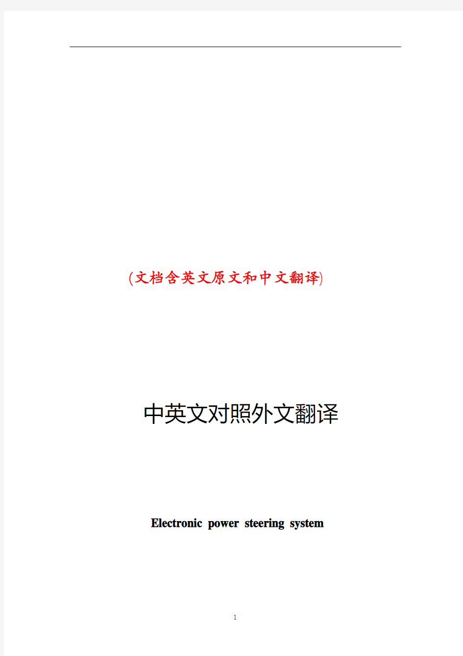
Electrically powered steering uses an electric motor to drive either the power steering hydraulic pump or the steering linkage directly. The power steering function is therefore independent of engine speed, resulting in significant energy savings.
How it works :
Conventional power steering systems use an engine accessory belt to drive the pump, providing pressurized fluid that operates a piston in the power steering gear or actuator to assist the driver.
In electro-hydraulic steering, one electrically powered steering concept uses a high efficiency pump driven by an electric motor. Pump speed is regulated by an electric controller to vary pump pressure and flow, providing steering efforts tailored for different driving situations. The pump can be run at low speed or shut off to provide energy savings during straight ahead driving (which is most of the time in most world markets).
Direct electric steering uses an electric motor attached to the steering rack via a gear mechanism (no pump or fluid). A variety of motor types and gear drives is possible. A microprocessor controls steering dynamics and driver effort. Inputs include vehicle speed and steering, wheel torque, angular position and turning rate.
Working In Detail:
A "steering sensor" is located on the input shaft where it enters the
sensor" that converts steering torque input and its direction into voltage signals, and a "rotation sensor" that converts the rotation speed and direction into voltage signals. An "interface" circuit that shares the same housing converts the signals from the torque sensor and rotation sensor into signals the control electronics can process.
Inputs from the steering sensor are digested by a microprocessor control unit that also monitors input from the vehicle's speed sensor. The sensor inputs are then compared to determine how much power assist is required according to a preprogrammed "force
map" in the control unit's memory. The control unit then sends out the appropriate command to the "power unit" which then supplies the electric motor with current. The motor pushes the rack to the right or left depending on which way the voltage flows (reversing the current reverses the direction the motor spins). Increasing the current to the motor increases the amount of power assist.
The system has three operating modes: a "normal" control mode in which left or right power assist is provided in response to input from the steering torque and rotation sensor's inputs; a "return" control mode which is used to assist steering return after completing a turn; and a "damper" control mode that changes with vehicle speed to improve road feel and dampen kickback.
If the steering wheel is turned and held in the full-lock position and steering assist reaches a maximum, the control unit reduces current to the electric motor to prevent an overload situation that might damage the motor. The control unit is also designed to protect the motor against voltage surges from a faulty alternator or charging problem.
The electronic steering control unit is capable of self-diagnosing faults by monitoring the system's inputs and outputs, and the driving current of the electric motor. If a problem occurs, the control unit turns the system off by actuating a fail-safe relay in the power unit. This eliminates all power assist, causing the system to revert back to manual steering. A dash EPS warning light is also illuminated to alert the driver. To diagnose the problem, a technician jumps the terminals on the service check connector and reads out the trouble codes.
click here to see a bigger
Electric power steering systems promise weight reduction, fuel savings and package flexibility, at no cost penalty.
Europe's high fuel prices and smaller vehicles make a fertile testbed for electric steering, a technology that promises automakers weight savings and fuel economy gains. And in a short time, electric steering will make it to the U.S., too. "It's just just a matter of time," says Aly Badawy, director of research and development for Delphi Saginaw Steering Systems in Saginaw, Mich. "The issue was cost and that's behind us now. By 2002 here in the U.S. the cost of electric power steering will absolutely be a wash over hydraulic."
Today, electric and hybrid-powered vehicles (EV), including Toyota's Prius and GM's EV-1, are the perfect domain for electric steering. But by 2010, a TRW Inc. internal study estimates that one out of every three cars produced in the world will be equipped with some form of electrically-assisted steering. The Cleveland-based supplier claims its new steering systems could improve fuel economy by up to 2 mpg, while enhancing handling. There are true bottom-line benefits as well for automakers by reducing overall costs and decreasing assembly time, since there's no need for pumps, hoses and fluids.
Another claimed advantage is shortened development time. For instance, a Delphi group developed E-TUNE, a ride-and-handling software package that can be run off a laptop computer. "They can take that computer and plug it in, attach it to the controller and change all the handling parameters -- effort level, returnability, damping -- on the fly," Badawy says. "It used to take months." Delphi has one OEM customer that should start low-volume production in '99.Electric steering units are normally placed in one of three positions: column-drive, pinion-drive and rack-drive. Which system will become the norm is still unclear. Short term, OEMs will choose the steering system that is easiest to integrate into an existing platform. Obviously,
greater potential comes from designing the system into an all-new platform."We have all three designs under consideration," says Dr. Herman Strecker, group vice president of steering systems division at ZF in Schwaebisch Gmuend, Germany. "It's up to the market and OEMs which version finally will be used and manufactured.""The large manufacturers have all grabbed hold of what they consider a core technology," explains James Handysides, TRW vice president, electrically assisted steering in Sterling Heights, Mich. His company offers a portfolio of electric steering systems (hybrid electric, rack-, pinion-, and column-drive). TRW originally concentrated on what it still believes is the purest engineering solution for electric steering--the rack-drive system. The system is sometimes refered to as direct drive or ball/nut drive.Still, this winter TRW hedged its bet, forming a joint venture with LucasVarity. The British supplier received $50 million in exchange for its electric column-drive steering technology and as sets. Initial production of the column and pinion drive electric steering systems is expected to begin in Birmingham, England, in 2000.
"What we lack is the credibility in the steering market," says Brendan Conner, managing director, TRW/LucasVarity Electric Steering Ltd. "The combination with TRW provides us with a good opportunity for us to bridge that gap." LucasVarity currently has experimental systems on 11 different vehicle types, mostly European. TRW is currently supplying its EAS systems for Ford and Chrysler EVs in North America and for GM's new Opel Astra.
In 1995, according to Delphi, traditional hydraulic power steering systems were on 7596 of all vehicles sold globally. That 37-million vehicle pool consumes about 10 million gallons in hydraulic fluid that could be superfluous, if electric steering really takes off.
The present invention relates to an electrically powered drive mechamsm for providing powered assistance to a vehicle steering mechanism. According to one aspect of the present invention, there is provided an electrically powered driven mechanism for providing powered assistance to a vehicle steering mechanism having a manually rotatable member for operating the steering mechanism, the drive mechanism including a torque sensor operable to sense torque being manually applied to the rotatable member, an electrically powered drive motor drivingly connected to the rotatable member and a controller which is arranged to control the speed and direction of rotation of the drive motor in response to signals received from the torque sensor, the torque sensor including a sensor shaft adapted for connection to the rotatable member to form an extension thereof so that torque is transmitted through said sensor shaft when the rotatable member is manually rotated and a strain gauge mounted on the sensor shaft for producing a signal indicative of the amount of torque being transmitted through said shaft.Preferably the sensor shaft is non-rotatably mounted at one axial end in a first coupling member and is non-rotatably mounted at its opposite axial end in a second coupling member, the first and second coupling members being inter-engaged to permit limited rotation therebetween so that torque under a predetermined limit is transmitted by the sensor shaft only and so that torque above said predetermined limit is transmitted through the first and second coupling members.The first and second coupling members are preferably arranged to act as a
bridge for drivingly connecting first and second portions of the rotating member to one another.Preferably the sensor shaft is of generally rectangular cross-section throughout the majority of its length.Preferably the strain gauge includes one or more SAW resonators secured to the sensor shaft.Preferably the motor is drivingly connected to the rotatable member via a clutch.Preferably the motor includes a gear box and is concentrically arranged relative to the rotatable member.Various aspects of the present invention will hereafter be described, with reference to the accompanying drawings, in which :Figure 1 is a diagrammatic view of a vehicle steering mechanism including an electrically powered drive mechanism according to the present invention,Figure 2 is a flow diagram illustrating interaction between various components of the drive mechanism shown in Figure 1 ,Figure 3 is an axial section through the drive mechanism shown in Figure 1, Figure 4 is a sectional view taken along lines IV-IV in Figure 3,Figure 5 is a more detailed exploded view of the input drives coupling shown in Figure 3, andFigure 6 is a more detailed exploded view of the clutch showing in Figure 3. Referring initially to Figure 1 , there is shown a vehicle steering mechanism 10 drivingly connected to a pair of steerable road wheels The steering mechanism 10 shown includes a rack and pinion assembly 14 connected to the road wheels 12 via joints 15. The pinion(not shown) of assembly 14 is rotatably driven by a manually rotatable member in the form of a steering column 18 which is manually rotated by a steering wheel 19.The steering column 18 includes an electric powered drive mechanism 30 which includes an electric drive motor (not shown in Figure 1) for driving the pinion in response to torque loadings in the steering column 18 in order to provide power assistance for the operative when rotating the steering wheel 19.As schematically illustrated in Figure 2, the electric powered drive mechanism includes a torque sensor20 which measures the torque applied by the steering column 18 when driving the pinion and supplies a signal to a controller 40. The controller 40 is connected to a drive motor 50 and controls the electric current supplied to the motor 50 to control the amount of torque generated by the motor 50 and the direction of its rotation.The motor 50 is drivingly connected to the steering column 18 preferably via a gear box 60, preferably an epicyclic gear box, and a clutch 70. The clutch 70 is preferably permanently engaged during normal operation and is operative under certain conditions to isolate drive from the motor 50 to enable the pinion to be driven manually through the drive mechanism 30. This is a safety feature to enable the mechanism to function in the event of the motor 50 attempting to drive the steering column too fast and/or in the wrong direction or in the case where the motor and/or gear box have seized.
The torque sensor 20 is preferably an assembly including a short sensor shaft on which is mounted a strain gauge capable of accurately measuring strain in the sensor shaft brought about by the application of torque within a predetermined range.Preferably the predetermined range of torque which is measured is 0-lONm; more preferably is about l-5Nm.Preferably the range of measured torque corresponds to about 0-1000 microstrain and the construction of the sensor shaft is chosen such that a torque of 5Nm will result in a twist of less than 2° in the shaft, more preferably less than 1 °.Preferably the strain gauge is a SAW resonator, a suitable SAW
resonator being described in WO91/13832. Preferably a configuration similar to that shown in Figure 3 of WO91/13832 is utilised wherein twoSAW resonators are arranged at 45° to the shaft axis and at 90° to one another.Preferably the resonators operate with a resonance frequency of between 200-400 MHz and are arranged to produce a signal to the controller 40 of 1 MHz ±500 KHz depending upon the direction of rotation of the sensor shaft. Thus, when the sensor shaft is not being twisted due to the absence of torque, it produces a 1 MHz signal.When the sensor shaft is twisted in one direction it produces a signal between 1.0 to 1.5 MHz. When the sensor shaft is twisted in the opposite direction it produces a signal between 1.0 to 0.5 MHz. Thus the same sensor is able to produce a signal indicative of the degree of torque and also the direction of rotation of the sensor shaft.Preferably the amount of torque generated by the motor in response to a measured torque of between 0-10Nm is 0-40Nm and for a measured torque of between l-5Nm is 0-25Nm.Preferably a feed back circuit is provided whereby the electric current being used by the motor is measured and compared by the controller 40 to ensure that the motor is running in the correct direction and providing the desired amount of power assistance. Preferably the controller acts to reduce the measured torque to zero and so controls the motor to increase its torque output to reduce the measured torque.A vehicle speed sensor (not shown) is preferably provided which sends a signal indicative of vehicle speed to the controller. The controller uses this signal to modify the degree of power assistance provided in response to the measured torque.Thus at low vehicle speeds maximum power assistance will be provided and a high vehicle speeds minimum power assistance will be provided.The controller is preferably a logic sequencer having a field programmable gate array for example a XC 4005 as supplied by Xilinx. Such a controller does not rely upon software and so is able to function more reliably in a car vehicle environment. It is envisaged that a logic sequence not having a field programmable array may be used.
Electronic power steering system (English as EPS), and hydraulic power steering system (HPS) compared to, EPS has many advantages.
The advantage is that the EPS:
1) high efficiency. HPS efficiency is very low, generally 60% to 70%, while EPS and electrical connections, high efficiency, and some can be as high as 90 percent.
2) less energy consumption. Automobile traffic in the actual process, at the time to about 5 percent of the time travelling, the HPS system, engine running, the pumps will always be in working condition, the oil pipeline has been in circulation, so that vehicle fuel consumption rate by 4 % To 6%, while EPS only when needed for energy, vehicle fuel consumption rates only increased by 0.5 percent.
3) "Road sense of" good. Because EPS internal use of rigid, system of the lag can be controlled by software, and can be used in accordance with the operation of the driver to adjust.
4) back to being good. EPS simple structure of small internal resistance, is a good back, get back to being the best characteristics, improve vehicle handling and stability.
5) little environmental pollution. HPS hydraulic circuit in the hydraulic hoses and connectors, the existence of oil leaking, but hydraulic hoses can not be recovered, the environmental pollution are to a certain extent, while EPS almost no pollution to the environment.
6) can be independent of the engines work. EPS for battery powered devices, as long as sufficient battery power, no matter what the condition for the engine, can produce power role.
7) should have a wide range.
8) easy to assemble and good layout.
Now, power steering systems of some cars have become the standard-setting, the whole world about half of the cars used to power steering. With the development of automotive electronics technology, some cars have been using electric power steering gear, the car of the economy, power and mobility has improved. Electric power steering device on the car is a new power steering system device, developed rapidly in recent years both at home and abroad, because of its use of programmable electronic control devices, the flexibility in the same time there are also potential safety problems. In the analysis This unique product on the basis of the author of the characteristics of electronic control devices, security clearance just that the factors that deal with security measures, and discussed a number of concerns the safety of specific issues. The results show that : Existing standards can not meet the electric power steering device security needs and made the electric power steering device safety evaluation of the idea. Research work on the electric power steering device development and evaluation of reference value.
电子动力转向系统
图1
电子动力转向系统的工作原理
电子动力转向系统是通过一个电动机来驱动动力方向盘液压泵或直接驱动转向联动装置。
电子动力转向的功能由于不依赖于发动机转速,所以能节省能源电子动力转向系统是这样运行的
传统的动力方向盘系统使用一条引擎辅助传送带驾驶泵浦,提供操作在动力方向盘齿轮或作动器的一个活塞协助司机的被加压的流体。在电动液压的指点,一个电子动力方向盘概念使用一台电动机驾驶的一个高效率泵浦。泵浦速度是由一个电控制器调控的变化泵浦压力和流程,提供被剪裁的指点努力为不同的驾驶的情况。泵浦可以跑在低速或关闭提供节能在大多时间在多数世界市场上)直向前的驾驶期间(直接电指点使用一台电动机附加指点机架通过齿轮机构(没有泵浦或流体)。各种各样的马达类型和齿轮驱动是可能的。微处理器控制指点动力学和司机努力。输入包括车速和指点、轮子扭矩,角位和转动率。
工作运行时的具体细节:
A “指点传感器”位于它进入传动箱住房的输入轴。指点传感器实际上是在一个的二个传感器:那“扭矩的传感器”
转换指点扭矩输入和它的方
向成电压信号,并且那“自转的传感器”转换转动速度和方向成电压信号。分享同一套住房的“接口”电路转换从扭矩传感器和自转传感器的信号成控制电子学可能处理的信号。从指点传感器的输入由那微处理器的控制单元消化也监测从车速传感器的输入。传感器输入然后被比较确定多少机械化根据一张被预编程序的“力量地图”需要在控制单元的记忆。控制单元然后派出适当的命令对然后供给电动机以潮流的“电源装置”。马达推挤机架在右边或左根据哪个方式电压流动(扭转潮流扭转方向马达旋转)。增加潮流对马达增加功率协助。系统有三种操作方式:左边或右边机械化提供以回应从指点扭矩和自转传感器的输入的输入的“正常”控制方式; 被用于在完成轮以后协助指点回归的“回归”控制方式; 并且改变与车速改进路感受和挫伤佣金的“更加潮湿的”控制方式。如果方向盘被转动,并且举行在充分锁位置和指点协助到达最大值,控制单元使潮流降低到电动机防止也许损坏马达的超载情况。控制单元也被设计保护马达以防止电压浪涌免受一个有毛病的交流发电机或充电的问题。
电子转向控制单位有能力在自我诊断的缺点通过监测系统输入和产品和电动机的激励电流上。如果问题发生,控制单元通过开动在电源装置的一个故障自动保险的中转关闭系统。这消灭所有机械化,造成系统恢复回到手工指点。破折号EPS警告灯也被阐明警告司机。要诊断问题,技术员跳服务检查连接器的终端并且读出问题代码。
图2
电子动力方向盘机制
当前发明与提供的供给动力的援助一电子功率驱动器马达关连给车操纵机构。根据当前发明的一个方面,那里为提供供给动力的援助提供一个电子功率驱动器机制给有车的操纵机构一名手动地可旋转的成员为操作操纵机构、传动机构
On the vehicle sideslip angle estimation through neural networks: Numerical and experimental results. S. Melzi,E. Sabbioni Mechanical Systems and Signal Processing 25 (2011):14~28 电脑估计车辆侧滑角的数值和实验结果 S.梅尔兹,E.赛博毕宁 机械系统和信号处理2011年第25期:14~28
摘要 将稳定控制系统应用于差动制动内/外轮胎是现在对客车车辆的标准(电子稳定系统ESP、直接偏航力矩控制DYC)。这些系统假设将两个偏航率(通常是衡量板)和侧滑角作为控制变量。不幸的是后者的具体数值只有通过非常昂贵却不适合用于普通车辆的设备才可以实现直接被测量,因此只能估计其数值。几个州的观察家最终将适应参数的参考车辆模型作为开发的目的。然而侧滑角的估计还是一个悬而未决的问题。为了避免有关参考模型参数识别/适应的问题,本文提出了分层神经网络方法估算侧滑角。横向加速度、偏航角速率、速度和引导角,都可以作为普通传感器的输入值。人脑中的神经网络的设计和定义的策略构成训练集通过数值模拟与七分布式光纤传感器的车辆模型都已经获得了。在各种路面上神经网络性能和稳定已经通过处理实验数据获得和相应的车辆和提到几个处理演习(一步引导、电源、双车道变化等)得以证实。结果通常显示估计和测量的侧滑角之间有良好的一致性。 1 介绍 稳定控制系统可以防止车辆的旋转和漂移。实际上,在轮胎和道路之间的物理极限的附着力下驾驶汽车是一个极其困难的任务。通常大部分司机不能处理这种情况和失去控制的车辆。最近,为了提高车辆安全,稳定控制系统(ESP[1,2]; DYC[3,4])介绍了通过将差动制动/驱动扭矩应用到内/外轮胎来试图控制偏航力矩的方法。 横摆力矩控制系统(DYC)是基于偏航角速率反馈进行控制的。在这种情况下,控制系统使车辆处于由司机转向输入和车辆速度控制的期望的偏航率[3,4]。然而为了确保稳定,防止特别是在低摩擦路面上的车辆侧滑角变得太大是必要的[1,2]。事实上由于非线性回旋力和轮胎滑移角之间的关系,转向角的变化几乎不改变偏航力矩。因此两个偏航率和侧滑角的实现需要一个有效的稳定控制系统[1,2]。不幸的是,能直接测量的侧滑角只能用特殊设备(光学传感器或GPS惯性传感器的组合),现在这种设备非常昂贵,不适合在普通汽车上实现。因此, 必须在实时测量的基础上进行侧滑角估计,具体是测量横向/纵向加速度、角速度、引导角度和车轮角速度来估计车辆速度。 在主要是基于状态观测器/卡尔曼滤波器(5、6)的文学资料里, 提出了几个侧滑角估计策略。因为国家观察员都基于一个参考车辆模型,他们只有准确已知模型参数的情况下,才可以提供一个令人满意的估计。根据这种观点,轮胎特性尤其关键取决于附着条件、温度、磨损等特点。 轮胎转弯刚度的提出就是为了克服这些困难,适应观察员能够提供一个同步估计的侧滑角和附着条件[7,8]。这种方法的弊端是一个更复杂的布局的估计量导致需要很高的计算工作量。 另一种方法可由代表神经网络由于其承受能力模型非线性系统,这样不需要一个参
https://www.doczj.com/doc/c11220385.html,/finance/company/consumer.html Consumer finance company The consumer finance division of the SG group of France has become highly active within India. They plan to offer finance for vehicles and two-wheelers to consumers, aiming to provide close to Rs. 400 billion in India in the next few years of its operations. The SG group is also dealing in stock broking, asset management, investment banking, private banking, information technology and business processing. SG group has ventured into the rapidly growing consumer credit market in India, and have plans to construct a headquarters at Kolkata. The AIG Group has been approved by the RBI to set up a non-banking finance company (NBFC). AIG seeks to introduce its consumer finance and asset management businesses in India. AIG Capital India plans to emphasize credit cards, mortgage financing, consumer durable financing and personal loans. Leading Indian and international concerns like the HSBC, Deutsche Bank, Goldman Sachs, Barclays and HDFC Bank are also waiting to be approved by the Reserve Bank of India to initiate similar operations. AIG is presently involved in insurance and financial services in more than one hundred countries. The affiliates of the AIG Group also provide retirement and asset management services all over the world. Many international companies have been looking at NBFC business because of the growing consumer finance market. Unlike foreign banks, there are no strictures on branch openings for the NBFCs. GE Consumer Finance is a section of General Electric. It is responsible for looking after the retail finance operations. GE Consumer Finance also governs the GE Capital Asia. Outside the United States, GE Consumer Finance performs its operations under the GE Money brand. GE Consumer Finance currently offers financial services in more than fifty countries. The company deals in credit cards, personal finance, mortgages and automobile solutions. It has a client base of more than 118 million customers throughout the world
中英文对照外文翻译文 电子商务时代企业文化的再造 随着网络时代电子商务大规模发展,电子商务企业文化随之产生,它在一个企业在产生的一种新的价值观,使企业内部资源得到从新整合,在为企业带来降低交易成本,提高效率,缩短生产周期等诸多好处的同时,也对已有的企业文化发起了挑战。电子商务的兴起是一场由技术手段飞速发展而引发的商业运作模式的变革,传统经济活动的生存基础、运作方式和管理机制均发生了彻底改变,传统的企业文化也面临着巨大的冲击。 一、企业文化对企业价值的贡献 文化现象是一个国家和民族文明的主要见证。广义的文化,包括知识、信仰、艺术、道德、法律、习俗和任何人作为一名社会成员而获得的能力和习惯在内的复杂整体。作为“亚文化”的企业文化,对企业的生存与发展亦起着举足轻重的作用。企业文化是商品经济和市场经济的产物,符合市场经济的客观规律,体现企业的竞争实务、竞争精神和整体形象。所谓企业文化就是企业的经营管理哲学,企业面对所处的社会和商业环境,在长期的生产经营活动中,形成全体员工所接受和认同信守的、为争取事业成功的一套非正式规则。它表明企业奉行何种管理哲学,以及企业通过管理要达到一个什么样的目标。是经济管理的重要内容之一。企业文化意味着一个公司的价值观,而这些价值观成为公司员工活动和行为的规范。 企业文化的本源问题是如何增加企业利润,降低企业的成本和费用。它的要义就是怎么使企业能够有效的整合资源,以达到对外部的适应性,使公司在竞争中生存,进而实现持续发展。企业文化建设为企业开展文化管理指出一个明确的方向。企业文化建设的根本目的是建设能够对外竞争环境具有高度适应性,并能根据环境变换做出迅速反应的行为方式能力,这种能力其实就是企业所拥有的根据外部竞争的环境需要而对内部资源进行整合运用的能力。企业文化建设应促进这一能力系统的形成,并维持好这一能力系统。中国的许多企业例如海尔、联想等企业成功的秘诀之一就是发展了一整套公司理念、经营哲学,形成了自己独特的企业文化。 1、企业文化体现企业的形象和精神。树立良好的企业形象,需要企业文化的支撑。现
附录 附录A Braking system function is to make the car driving in accordance with the requirements of the pilot required even slow down park; They offend car has in various road conditions (including in the slope stability) in car; Make the downhill cars speed to be stable. For car up the role of brake is only in the car and role with the direction of the car driving direction opposite forces, and the size of these forces are random, do not control, so cars must be installed on a series of special equipment to achieve the function. Automobile brake system is to point to to ensure that the car in technology, improve the safe driving car average speed, etc., and the admiration installed in the car brake special brake institutions. In general automobile brake system including crane brake system and parking brake two sets of independent device. One crane brake device is a driver with feet to manipulate, and it said the foot brake. Parking brake device is a pilot with the hand, so it says of the manipulation of the hand brake. The function of the crane brake system is to make the car slow down or running in the shortest distance parking within. And parking brake function is to make had stopped the car on the road all keep still. But, sometimes, in an emergency, two braking device can be used at the same time and increase the effect of auto brake. Some special purpose of cars and often in the mountains cars, long and frequently brake will lead to crane brake system overheating, so in these cars often add all sorts of different types of auxiliary braking equipment, so as to speed up the hill stability. According to the braking energy situation, brake system can also be divided into human brake system, power brake system, and servo brake system, three. Human brake system to the driver's physical strength as braking energy; Power brake system engine power to the transformation of the air pressure or hydraulic braking energy as; And servo brake system is the most human and engine power as a brake energy. In addition, according to the braking energy transfer mode, brake system and can be divided into mechanical and hydraulic, pneumatic type and assolenoid style wait until a few kinds.
The development of automobile As the world energy crisis and the war and the energy consumption of oil -- and are full of energy in one day someday it will disappear without a trace. Oil is not inresources. So in oil consumption must be clean before finding a replacement. With the development of science and technology the progress of the society people invented the electric car. Electric cars will become the most ideal of transportation. In the development of world each aspect is fruitful especially with the automobile electronic technology and computer and rapid development of the information age. The electronic control technology in the car on a wide range of applications the application of the electronic device cars and electronic technology not only to improve and enhance the quality and the traditional automobile electrical performance but also improve the automobile fuel economy performance reliability and emission spurification. Widely used in automobile electronic products not only reduces the cost and reduce the complexity of the maintenance. From the fuel injection engine ignition devices air control and emission control and fault diagnosis to the body auxiliary devices are generally used in electronic control technology auto development mainly electromechanical integration. Widely used in automotive electronic control ignition system mainly electronic control fuel injection system electronic control ignition system electronic control automatic transmission electronic control ABS/ASR control system electronic control suspension system electronic control power steering system vehicle dynamic control system the airbag systems active belt system electronic control system and the automatic air-conditioning and GPS navigation system etc. With the system response the use function of quick car high reliability guarantees of engine power and reduce fuel consumption and emission regulations meet standards. The car is essential to modern traffic tools. And electric cars bring us infinite joy will give us the physical and mental relaxation. Take for example automatic transmission in road can not on the clutch can achieve automatic shift and engine flameout not so effective improve the driving convenience lighten the fatigue strength. Automatic transmission consists mainly of hydraulic torque converter gear transmission pump hydraulic control system electronic control system and oil cooling system etc. The electronic control of suspension is mainly used to cushion the impact of the body and the road to reduce vibration that car getting smooth-going and stability. When the vehicle in the car when the road uneven road can according to automatically adjust the height. When the car ratio of height low set to gas or oil cylinder filling or oil. If is opposite gas or diarrhea. To ensure and improve the level of driving cars driving stability. Variable force power steering system can significantly change the driver for the work efficiency and the state so widely used in electric cars. VDC to vehicle performance has important function it can according to the need of active braking to change the wheels of the car car motions of state and optimum control performance and increased automobile adhesion controlling and stability. Besides these appear beyond 4WS 4WD electric cars can greatly improve the performance of the value and ascending simultaneously. ABS braking distance is reduced and can keep turning skills effectively improve the stability of the directions simultaneously reduce tyre wear. The airbag appear in large programs protected the driver and passengers safety and greatly reduce automobile in collision of drivers and passengers in the buffer to protect the safety of life. Intelligent electronic technology in the bus to promote safe driving and that the other functions. The realization of automatic driving through various sensors. Except some smart cars equipped with multiple outside sensors can fully perception of information and traffic facilities
毕业设计(论文)外文参考文献及译文 英文题目Component-based Safety Computer of Railway Signal Interlocking System 中文题目模块化安全铁路信号计算机联锁系统 学院自动化与电气工程学院 专业自动控制 姓名葛彦宁 学号 200808746 指导教师贺清 2012年5月30日
Component-based Safety Computer of Railway Signal Interlocking System 1 Introduction Signal Interlocking System is the critical equipment which can guarantee traffic safety and enhance operational efficiency in railway transportation. For a long time, the core control computer adopts in interlocking system is the special customized high-grade safety computer, for example, the SIMIS of Siemens, the EI32 of Nippon Signal, and so on. Along with the rapid development of electronic technology, the customized safety computer is facing severe challenges, for instance, the high development costs, poor usability, weak expansibility and slow technology update. To overcome the flaws of the high-grade special customized computer, the U.S. Department of Defense has put forward the concept:we should adopt commercial standards to replace military norms and standards for meeting consumers’demand [1]. In the meantime, there are several explorations and practices about adopting open system architecture in avionics. The United Stated and Europe have do much research about utilizing cost-effective fault-tolerant computer to replace the dedicated computer in aerospace and other safety-critical fields. In recent years, it is gradually becoming a new trend that the utilization of standardized components in aerospace, industry, transportation and other safety-critical fields. 2 Railways signal interlocking system 2.1 Functions of signal interlocking system The basic function of signal interlocking system is to protect train safety by controlling signal equipments, such as switch points, signals and track units in a station, and it handles routes via a certain interlocking regulation. Since the birth of the railway transportation, signal interlocking system has gone through manual signal, mechanical signal, relay-based interlocking, and the modern computer-based Interlocking System. 2.2 Architecture of signal interlocking system Generally, the Interlocking System has a hierarchical structure. According to the function of equipments, the system can be divided to the function of equipments; the system
Automobile Brake System The braking system is the most important system in cars. If the brakes fail, the result can be disastrous. Brakes are actually energy conversion devices, which convert the kinetic energy (momentum) of the vehicle into thermal energy (heat).When stepping on the brakes, the driver commands a stopping force ten times as powerful as the force that puts the car in motion. The braking system can exert thousands of pounds of pressure on each of the four brakes. Two complete independent braking systems are used on the car. They are the service brake and the parking brake. The service brake acts to slow, stop, or hold the vehicle during normal driving. They are foot-operated by the driver depressing and releasing the brake pedal. The primary purpose of the parking brake is to hold the vehicle stationary while it is unattended. The parking brake is mechanically operated by when a separate parking brake foot pedal or hand lever is set. The brake system is composed of the following basic c omponents: the “master cylinder” which is located under the hood, and is directly connected to the brake pedal, converts driver foot’s mechanical pressure into hydraulic pressure. Steel “brake lines” and flexible “brake hoses” connect the master cylinder to the cylinders” located at each wheel. Brake fluid, specially designed to work in extreme conditions, fills the system. “Shoes” and “pads” are pushed by cylinders to contact the “drums” and “rotors” thus causing drag, which (hopefully) slows the car. The typical brake system consists of disk brakes in front and either disk or drum brakes in the rear connected by a system of tubes and hoses that link the brake at each wheel to the master cylinder (Figure).
汽车保险中英文对照外文翻译文献(文档含英文原文和中文翻译)
汽车保险 汽车保险是在事故后保证自己的财产安全合同。尽管联邦法律没有强制要求,但是在大多数州(新罕布什和威斯康星州除外)都要求必须购买汽车保险;在各个州都有最低的保险要求。在鼻腔只购买汽车保险的两个州,如果没有足够的证据表明车主财力满足财务责任法的要求,那么他就必须买一份汽车保险。就算没有法律规定,买一份合适的汽车保险对司机避免惹上官和承担过多维修费用来说都是非常实用的。 依据美国保险咨询中心的资料显示,一份基本的保险单应由6个险种组成。这其中有些是有州法律规定,有些是可以选择的,具体如下: 1.身体伤害责任险 2.财产损失责任险 3.医疗险或个人伤害保护险 4.车辆碰撞险 5.综合损失险 6.无保险驾驶人或保额不足驾驶人险 责任保险 责任险的投保险额一般用三个数字表示。不如,你的保险经纪人说你的保险单责任限额是20/40/10,这就代表每个人的人身伤害责任险赔偿限额是2万美元,每起事故的热身上海责任险赔偿限额是4万美元,每起事故的财产损失责任险的赔偿限额是1万美元。 人身伤害和财产损失责任险是大多数汽车保险单的基础。要求汽车保险的每个州都强令必须投保财产损失责任险,佛罗里达是唯一要求汽车保险但不要求投保人身伤害责任险的州。如果由于你的过错造成了事故,你的责任险会承担人身伤害、财产损失和法律规定的其他费用。人身伤害责任险将赔偿医疗费和误工工资;财产损失责任险将支付车辆的维修及零件更换费用。财产损失责任险通常承担对其他车辆的维修费用,但是也可以对你的车撞坏的灯杆、护栏、建筑物等其他物品的损坏进行赔偿。另一方当事人也可以决定起诉你赔偿精神损失。
Dashboard From Wikipedia, the free encyclopedia This article is about a control panel placed in the front of the car. For other uses, see Dashboard (disambiguation). The dashboard of a Bentley Continental GTC car A dashboard (also called dash, instrument panel (IP), or fascia) is a control panel located directly ahead of a vehicle's driver, displaying instrumentation and controls for the vehicle's operation. Contents 1.Etymology 2.Dashboard features 3.Padding and safety 4.Fashion in instrumentation 5.See also 6.References Etymology Horse-drawn carriage dashboard Originally, the word dashboard applied to a barrier of wood or leather fixed at the front of a horse-drawn carriage or sleigh to protect the driver from mud or other debris "dashed up" (thrown up) by the horses' hooves.[1] Commonly these boards did not perform any additional function other than providing a convenient handhold for ascending into the driver's seat, or a small clip with which to secure the reins when not in use. When the first "horseless carriages" were constructed in the late 19th century, with engines mounted beneath the driver such as the Daimler Stahlradwagen, the simple dashboard was retained to protect occupants from debris thrown up by the cars' front wheels. However, as car design evolved to position the motor in front of the driver, the dashboard became a panel that protected vehicle occupants from the heat and oil of the engine. With gradually increasing mechanical complexity, this panel formed a convenient location for the placement of gauges and minor controls, and from this evolved the modern instrument panel,
跨境电商外文文献综述 (文档含英文原文和中文翻译) 译文: 本地化跨境电子商务的模型 摘要 通过对国际供应链的B2B电子商务交易量的快速增长和伊朗快速增加的跨境交易业务,跨境电商过程的有效管理对B2B电子商务系统十分重要。本文对局部模型的结构是基于B2B电子商务的基础设施三大层,消息层、业务流程层和内容层。由于伊朗的电子商务的要求,每一层的需要适当的标准和合适的方案的选择。当电子文件需要移动顺利向伊朗,建议文件的标准为文件内容支持纸质和电子文件阅读。验证提出的模型是通过案例研究方法呈现一到四阶段的情景。本文试图通过交换商业文件在贸易过程中这一局部模型,实现在全球电子贸易供应链更接近区域单一窗口建设的关键目标。 关键词:电子商务;跨境贸易;电子文档管理;国际供应链
1.简介 电子商务是关于在互联网或其他网络电子系统购买和销售产品或服务。术语B2B(企业对企业),描述了企业间的电子商务交易,如制造商和批发商,或批发商和零售商之间。本文的研究目标是上两个不同国家贸易商之间的通信。今天的世界贸易组织的主要目标之一是建立区域单一窗口,可以提高世界各地的贸易便利化。建立区域单一窗口需要跨境海关,可以有效地交换贸易文件。因此,首先,简化跨境贸易文件的关键在于朝着国家单一窗口移动。然后,区域单一窗口可以授权国家之间的通信。电子商务模型是基于三个主要逻辑层的研究。这三个层消息传输层,业务处理层和内容层。本文的局部模型是一种能够自动交换读取文件的过程。通过与东亚和中东国家的建立区域单一窗口可以在将来得到改善的更多的互操作性,从而建立伊朗国家单一窗口 在本文的第二部分讨论引进国际供应链中的跨境B2B模式所需的基本概念和标准。第三部分介绍在大的模型中引入的组件功能和范围。第四部分讨论了B2B交易层模型的定位,最后结束本文。 2.背景 在本节中,除了了解B2B电子商务在伊朗的情况,还有参考模型的背景等概念以及讨论B2B电子商务跨境模式的本土化。 2.1 B2B电子商务在伊朗 如今伊朗在贸易进程的变现是一个关键的贸易成功点。伊朗和许多其他国家接壤,它的进口和出口过程可以通过公路,铁路,海上和空中的方式来完成。因此,这个国家的中部和战略作用,使得它在亚洲和中东地区货物运输的主要贸易点。今天,在伊朗海关几乎所有的贸易过程通过纸质表格完成,由商务部提供的电子服务仅限于谁该国境内交易的商人。今天,伊朗海关几乎所有的贸易流程都是通过纸质表格来完成的,商务部给出的电子服务只限于该国的商人。介绍了模型试图简化在伊朗交易的跨境电子商务供应链交换电子文件的过程。这里提到的一些系统,由商务部在伊朗的电子服务被提及:进口订单管理系统。贸易统计制度。伊朗法典伊朗。这些电子系统的主要使用,以促进在伊朗贸易过程。这里提到的系统作为独立的贸易者可与建议本文模型在未来的作用。在亚洲的区域性单
毕业设计(论文)外文文献翻译 文献、资料中文题目:汽车制动系统 文献、资料英文题目: 文献、资料来源: 文献、资料发表(出版)日期: 院(部): 专业:汽车检测与维修 班级: 姓名: 学号: 指导教师: 翻译日期: 2017.02.14
Automobile Brake System The braking system is the most important system in cars. If the brakes fail, the result can be disastrous. Brakes are actually energy conversion devices, which convert the kinetic energy (momentum) of the vehicle into thermal energy (heat).When stepping on the brakes, the driver commands a stopping force ten times as powerful as the force that puts the car in motion. The braking system can exert thousands of pounds of pressure on each of the four brakes. Two complete independent braking systems are used on the car. They are the service brake and the parking brake. The service brake acts to slow, stop, or hold the vehicle during normal driving. They are foot-operated by the driver depressing and releasing the brake pedal. The primary purpose of the brake is to hold the vehicle stationary while it is unattended. The parking brake is mechanically operated by when a separate parking brake foot pedal or hand lever is set. The brake system is composed of the following basic components: the “master cylinder” which is located under the hood, and is directly connected to the brake pedal, converts driver foot’s mechanical pressure into hydraulic pressure. Steel “brake lines” and flexible “brake hoses” connect the master cylinder to the “slave cylinders” located at each wheel. Brake fluid, specially designed to work in extreme conditions, fills the system. “Shoes” and “pads” are pushed by the slave cy linders to contact the “drums” and “rotors” thus causing drag, which (hopefully) slows the car. The typical brake system consists of disk brakes in front and either disk or drum brakes in the rear connected by a system of tubes and hoses that link the brake at each wheel to the master cylinder (Figure). Basically, all car brakes are friction brakes. When the driver applies the