Designation:D1125–95(Reapproved2005)An American National Standard Standard Test Methods for
Electrical Conductivity and Resistivity of Water1
This standard is issued under the?xed designation D1125;the number immediately following the designation indicates the year of
original adoption or,in the case of revision,the year of last revision.A number in parentheses indicates the year of last reapproval.A
superscript epsilon(e)indicates an editorial change since the last revision or reapproval.
This standard has been approved for use by agencies of the Department of Defense.
1.Scope
1.1These test methods cover the determination of the electrical conductivity and resistivity of water.The following test methods are included:
Range Sections Test Method A—Field and Routine Laboratory10to20000012to18 Measurement of Static(Non-Flowing)
Samples
μS/cm
Test Method B—Continuous In-Line Measure5to20000019to23 mentμS/cm
1.2These test methods have been tested in reagent water.It is the user’s responsibility to ensure the validity of these test methods for waters of untested matrices.
1.3For measurements below the range of these test meth-ods,refer to Test Method D5391.
1.4This standard does not purport to address all of the safety concerns,if any,associated with its use.It is the responsibility of the user of this standard to establish appro-priate safety and health practices and determine the applica-bility of regulatory limitations prior to use.
2.Referenced Documents
2.1ASTM Standards:2
D1066Practice for Sampling Steam
D1129Terminology Relating to Water
D1192Speci?cation for Equipment for Sampling Water and Steam in Closed Conduits3
D1193Speci?cation for Reagent Water
D2186Test Method for Deposit-Forming Impurities in Steam
D2777Practice for Determination of Precision and Bias of Applicable Methods of Committee D19on Water
D3370Practices for Sampling Water from Closed Conduits
D4519Test Method for On-Line Determination of Anions and Carbon Dioxide in High Purity Water by Cation Exchange and Degassed Cation Conductivity
D5391Test Method for Electrical Conductivity and Resis-tivity of a Flowing High Purity Water Sample
E1Speci?cation for ASTM Liquid-in-Glass Thermometers
3.Terminology
3.1De?nitions:
3.1.1electrical conductivity—the reciprocal of the a-c re-sistance in ohms measured between opposite faces of a centimetre cube of an aqueous solution at a speci?ed tempera-ture.
N OTE1—The unit of electrical conductivity is siemens per centimetre. (The previously used units of mhos/cm are numerically equivalent to S/cm.)The actual resistance of the cell,R
x
,is measured in ohms.The
conductance,1/R
x
,is directly proportional to the cross-sectional area,A (in cm2),and inversely proportional to the length of the path,L(in cm):
1/R x5K·A/L
The conductance measured between opposite faces of a centimetre cube,K,is called conductivity.Conductivity values are usually expressed in microsiemens/centimetre or in siemens/centimetre at a speci?ed temperature,normally25°C.
3.1.2electrical resistivity—the a-c resistance in ohms mea-sured between opposite faces of a centimetre cube of an aqueous solution at a speci?ed temperature.
N OTE2—The unit of electrical resistivity is ohm-centimetre.The actual
resistance of the cell,R
x
,is measured in ohms,and is directly proportional to the length of the path,L(in cm),and inversely proportional to the cross-sectional area,A(in cm2):
R x5R·L/A
The resistance measured between opposite faces of a centi-metre cube,R,is called resistivity.Resistivity values are usually expressed in ohm·centimetre,or in megohm·centime-tre,at a speci?ed temperature,normally25°C.
3.1.3For de?nitions of other terms used in these methods, refer to Terminology D1129.
3.2Symbols:Symbols:
3.2.1Symbols used in the equations in Sections14and16 are de?ned as follows:
J=cell constant,cm?1,
K=conductivity at25°C,μS/cm,
1These test methods are under the jurisdiction of Committee D19on Water and
are the direct responsibility of Subcommittee D19.03on Sampling of Water and
Water-Formed Deposits,Surveillance of Water,and Flow Measurement of Water.
Current edition approved April1,2005.Published April2005.Originally
approved https://www.doczj.com/doc/c06873734.html,st previous edition approved in1999as D1125–95(1999).
2For referenced ASTM standards,visit the ASTM website,https://www.doczj.com/doc/c06873734.html,,or
contact ASTM Customer Service at service@https://www.doczj.com/doc/c06873734.html,.For Annual Book of ASTM
Standards volume information,refer to the standard’s Document Summary page on
the ASTM website.
3Withdrawn.
Copyright?ASTM International,100Barr Harbor Drive,PO Box C700,West Conshohocken,PA19428-2959,United States. --``,`,,``,`,,,,`,,,`,,`,```,``-`-`,,`,,`,`,,`---
K x =measured conductance,S,
K 1=conductivity of the KCl in the reference solution at the temperature of measurement (Table 1),μS/cm,
K 2=conductivity of the water used to prepare the reference solution,at the same temperature of measurement,μS/cm,Q =temperature correction factor (see Section 11),R =resistivity at 25°C,ohm ·cm,R x =measured resistance,ohm.
4.Signi?cance and Use
4.1These test methods are applicable for such purposes as impurity detection and,in some cases,the quantitative mea-surement of ionic constituents dissolved in waters.These include dissolved electrolytes in natural and treated waters,such as boiler water,boiler feedwater,cooling water,and saline and brackish water.
4.1.1Their concentration may range from trace levels in pure waters (1)4to signi?cant levels in condensed steam (see Test Methods D 2186and D 4519,and Ref (2)),or pure salt solutions.
4.1.2Where the principal interest in the use of conductivity methods is to determine steam purity,see Ref (3).These test methods may also be used for checking the correctness of water analyses (4).
5.Interferences
5.1Exposure of a sample to the atmosphere may cause changes in conductivity/resistivity,due to loss or gain of dissolved gases.This is extremely important in the case of very pure waters with low concentrations of dissolved ionized materials.The carbon dioxide,normally present in the air,can drastically increase the conductivity of pure waters by approxi-mately 1μS/cm.Contact with air should be avoided by using ?ow-through or in-line cell where feasible.Chemically pure inert gases,such as nitrogen or helium,may be used to blanket the surface of samples.
5.2Undissolved or slowly precipitating materials in the sample can form a coating on the electrodes of the conductivity
cell that may cause erroneous readings.For example,biofoul-ing of the cell or a build-up of ?lming amines may cause poor cell response.In most cases these problems can be eliminated by washing the cells with appropriate solvents.
5.3If an unshielded cell is used to measure the resistivity/conductivity of high resistivity water there is a possibility of electrical pickup causing erroneous reading.For this reason it is recommended that conductivity cells for this application be of coaxial shielded type or equivalent,and that the cables and instrument also be shielded.
6.Apparatus
6.1Measuring Circuit —The instrument may be a manually operated wheatstone bridge or the equivalent,or a direct reading analog or digital meter.Instruments shall energize the conductivity cell with alternating current and,together with the cell and any extension leadwire,shall be designed to reduce errors from the following sources:
6.1.1In highly conductive solutions —Uncompensated elec-trode polarization due to excessive current density at the electrode surfaces can cause negative conductivity errors.Insufficient series capacitance at the electrode/solution inter-face can allow charging effects to distort the a-c measurement and cause errors if not compensated.Leadwire resistance can add signi?cantly to the measured resistance.
6.1.2In low conductivity solutions —Excessive parallel ca-pacitance in the cell and extension leadwire can shunt the measurement and cause positive conductivity errors.Tempera-ture compensation errors can be signi?cant below 5μS/cm if variable coefficient algorithms are not employed as described in Test Method D 5391.
6.1.3These sources of error are minimized by an appropri-ate combination of a-c drive voltage,wave shape,frequency,phase correction,wave sampling technique and temperature compensation designed in by the instrument manufacturer.The instrument manufacturer’s recommendations shall be followed in selecting the proper cell constant,leadwire size,and length and maintenance of the electrode surface condition for the range of measurement.Calibration may be in either conduc-tivity or resistivity units.
6.1.4When an output signal is required from an on-line instrument,it shall be electrically isolated from the cell drive
4
The boldface numbers in parentheses refer to the list of references at the end of these test methods.
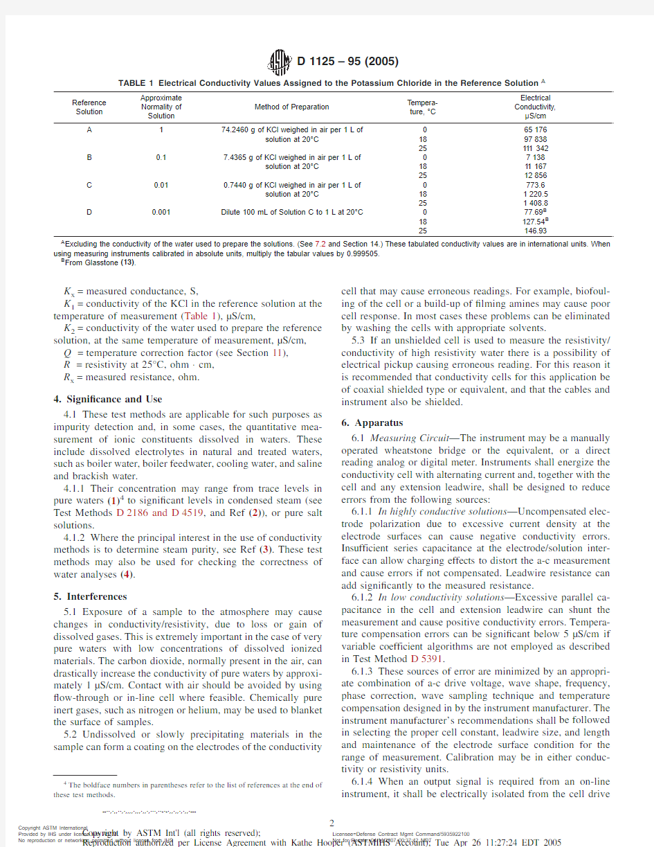
TABLE 1Electrical Conductivity Values Assigned to the Potassium Chloride in the Reference Solution A
Reference Solution
Approximate Normality of Solution
Method of Preparation
Tempera-ture,°C
Electrical Conductivity,μS/cm A
1
74.2460g of KCl weighed in air per 1L of
065176solution at 20°C 189783825111342B 0.1
7.4365g of KCl weighed in air per 1L of
07138solution at 20°C 18111672512856C 0.01
0.7440g of KCl weighed in air per 1L of
0773.6solution at 20°C 181220.5251408.8D 0.001
Dilute 100mL of Solution C to 1L at 20°C
077.69B 18127.54B 25
146.93
A
Excluding the conductivity of the water used to prepare the solutions.(See 7.2and Section 14.)These tabulated conductivity values are in international units.When using measuring instruments calibrated in absolute units,multiply the tabular values by 0.999505.B
From Glasstone (13)
.
--``,`,,``,`,,,,`,,,`,,`,```,``-`-`,,`,,`,`,,`---
circuit to prevent interaction between a solution ground at the cell and an external circuit ground.6.2Cells :
6.2.1Flow-through or in-line cells shall be used for mea-suring conductivities lower than 10μS/cm (resistivities higher than 100000ohm ·cm),to avoid contamination from the atmosphere.However,samples with conductivity greater than 10μS/cm may also be measured.In all other cases,pipet-type or dip cells can also be used.Pipet or dip cells may be used to measure samples in the range of 1to 10μS/cm if the sample is protected by an inert gaseous layer of nitrogen or helium.6.2.2A cell constant shall be chosen which will give a moderate cell resistance,matching the instrument manufactur-er’s requirements for the range of measurement.For laboratory bridges,Table 2provides conservative guidelines.
6.2.3Flow-through and in-line cells shall be mounted so that continuous ?ow of the sample through or past it is possible.Flow rate should be maintained at a constant rate consistent with the manufacturer’s recommendations for the cell being used,particularly at conductivities below 10μS/cm.The cell shall retain calibration under conditions of pressure,?ow,and temperature change,and shall exclude the atmo-sphere and be constructed of corrosion resistant,chemically inert materials.The chamber or cell shall be equipped with means for accurate measurement of the temperature.
6.2.4Platinized cells shall not be used for measurement of conductivities below 10μS/cm,except that a trace or ?ash of platinum black may be used on cells for measurements in the range of 0.1to 10μS/cm (see 9.4).Because of the cost and fragility of platinum cells,it is common practice to use titanium,monel,and graphite electrodes for measurements with accuracies on the order of 1%.Note that these electrodes may require special surface preparation.Titanium and monel electrodes are especially suitable for high resistance solutions such as ultrapure water,but may introduce a small surface resistance which limits their accuracy when the measured resistance is less than a few thousand ohms (1).
6.2.5It is recommended that cells intended for the measure-ment of conductivities below 10μS/cm be reserved exclusively for such applications.
6.3Temperature Probes :
6.3.1For Temperature Control —The measurement of tem-perature is necessary for control of a temperature bath,manual temperature compensation,or automatic temperature compen-sation,or all of these.Thermometers,thermistors,and resis-tance temperature detectors with accuracies of 60.1°C or better are acceptable for this application.An ASTM precision thermometer,Number 63C,as de?ned in Speci?cation E 1,is recommended.The calibration of temperature probes should be checked periodically by comparison to a reference temperature
probe whose calibration is traceable to the U.S.National Institute of Science and Technology (formerly NBS)or equiva-lent.
6.3.2For Temperature Correction —A thermometer accu-rate to 0.1°C is acceptable for this application,when the instrument is not provided with manual or automatic tempera-ture compensation.(See Section 11).
7.Reagents
7.1Purity of Reagents —Reagent grade chemicals shall be used in all tests.Unless otherwise indicated,it is intended that all reagents shall conform to the speci?cations of the Commit-tee on Analytical Reagents of the American Chemical Society,where such speci?cations are available.5Other grades may be used,provided it is ?rst ascertained that the reagent is of sufficiently high purity to permit its use without lessening the accuracy of the determination.
7.2Purity of Water —Unless otherwise indicated,references to water shall be understood to mean reagent water conforming to Speci?cation D 1193,Type I.In making up the potassium chloride solutions for cell constant determinations,use water of conductivity not greater than 1.5μS/cm.If necessary,stabilize to the laboratory atmosphere by aspirating air through the water from a fritted glass or stainless steel gas dispersion tube.The equilibrium point is reached when the conductivity re-mains constant but not greater than 1.5μS/cm.The equilibrium conductivity must be added to Table 1.
7.3Alcohol —95%ethyl alcohol.Alternatively,use isopro-pyl alcohol or methyl alcohol.
7.4Aqua Regia (3+1)—Mix 3volumes of concentrated hydrochloric acid (HCl,sp gr 1.19)with 1volume of concen-trated nitric acid (HNO 3,sp gr 1.42).This reagent should be used immediately after its preparation.7.5Ethyl Ether .
7.6Hydrochloric Acid (sp gr 1.19)—Concentrated HCl.7.7Hydrochloric Acid (1+1)—Mix 1volume of concen-trated HCl (sp gr 1.19)with 1volume of water.
7.8Platinizing Solution —Dissolve 1.5g of chloroplatinic acid (H 2PtCl 6·6H 2O)in 50mL of water containing 0.0125g of lead acetate (Pb(C 2H 3O 2)2).
7.9Potassium Chloride (KCl)—The assay of the potassium chloride must be 100.060.1%.This standardization grade of KCl is available from NIST and from commercial sources.Dry at 150°C for 2h or until weight loss is less than 0.02%;store in desiccator.
7.10Potassium Chloride Reference Solution A —Dissolve 74.2460g of KCl (weighed in air)in water and dilute to 1L at 2062°C in a Class A volumetric ?ask.
7.11Potassium Chloride Reference Solution B —Dissolve 7.4365g of KCl (weighed in air)in water and dilute to 1L at 2062°C in a Class A volumetric ?ask.
5
Reagent Chemicals,American Chemical Society Speci?cations ,American Chemical Society,Washington,DC.For suggestions on the testing of reagents not listed by the American Chemical Society,see Analar Standards for Laboratory Chemicals ,BDH Ltd.,Poole,Dorset,U.K.,and the United States Pharmacopeia and National Formulary ,U.S.Pharmaceutical Convention,Inc.(USPC),Rockville,MD.
TABLE 2Recommended Cell Constants for Various Conductivity
Ranges
Range of Conductivity,μS/cm
Cell Constant,cm ?1
0.05to 100.01to 0.110to 2000.1to 1200to 5000
1to 105000to 1000000
10to
100
7.12Potassium Chloride Reference Solution C—Dissolve 0.7440g of KCl(weighed in air)in water and to dilute1L at 2062°C in a Class A volumetric?ask.
7.13Potassium Chloride Reference Solution D—Dilute100 mL of reference solution C to1L with water at2062°C in a Class A volumetric?ask shortly before using.Store the solution in a glass-stoppered bottle of chemically resistant glass which has only been used for storage of this solution. N OTE3—The electrical conductivity of each of the referenced solutions is given in Table1.The values for electrical conductivities for the solutions are those of G.Jones and B.C.Bradshaw(5),con?rmed in1987 (6)and1989(7)by the National Institute of Standards and Technology (NIST).The data of T.Shedlovsky(8)are used for Solution D.Solutions A,B,and C were prepared by Jones and Bradshaw using the molal or demal basis by dissolving71.1352,7.4191,and0.7453g,respectively,of KCl(in vacuum)per1000g of solution(in vacuum).The method of preparation given in Table1includes the corrections to weights of KCl(in air against brass weights)per litre of solutions at20°C and assumes the density of KCl=1.98,density of brass=8.4,and the density of air=0.00118.The densities of1.0N,0.10N,and0.010N KCl at20°C, 1.04420,1.00280,and0.99871g/mL,respectively,were interpolated from the data in the International Critical Tables(9).
8.Sampling
8.1Samples shall be collected in accordance with Practice D1066,Speci?cation D1192,and Practices D3370,as appli-cable.
8.2Avoid exposure of the sample to atmospheres containing ammonia or acidic gases.Protect the sample to avoid gain or loss of dissolved gases,particularly if there is some delay before the conductivity measurements are made.Preferably, use a?ow-type cell for sampling and measuring condensed steam or water having a conductivity of less than10μS/cm. For waters in the range of5to10μS/cm,a dip-type cell may be used if a layer of chemically pure nitrogen or helium is maintained over the surface.
9.Preparation of Electrodes
9.1If the cell constant as checked does not fall within reasonable limits of its nominal value,it is necessary to clean or replatinize the electrodes or replace the cell.In general,no mechanical cleaning should be attempted.In high purity water measurements,where the presence of?nely divided platinum is undesirable due to its long retention of impurities,platini-zation of electrodes should be omitted,especially for testing of water having a conductivity below10μS/cm(see9.4).On the other hand,clean and well-platinized electrodes are increas-ingly important in testing water of higher conductivities, particularly above1000μS/cm.
9.2The cell manufacturer’s instructions may be followed for cleaning the electrodes as well as other parts of the cell.A suitable cleaning solution consists of a mixture of1part by volume of isopropyl alcohol,1part of ethyl ether,(with polymer cells,check compatibility)and1part of HCl(1+1). After cleaning,thoroughly?ush the cell with water.If the old platinum black coating is to be removed,judicious application of aqua regia to the electrodes,or electrolysis in HCl(sp gr 1.19)is frequently successful.
9.3Platinize the electrodes of the cell with H2PtCl6solu-tion.A suitable plating apparatus consists of a6volt a-c supply,a variable resistor,milliammeter,and an electrode.The deposit should present a black,velvety appearance and should adhere well to the electrode surface.The procedure for platinizing is not critical.Follow the manufacturer’s instructions or the following guidelines.Good platinized coatings are obtained using from 1.5to3coulombs/cm2of electrode area.For example,for an electrode having a total area(both sides)of10 cm2,the plating time at a current of20mA would be from121?2 to25min.The current density may be from1to4mA/cm2of electrode area.Plate the electrodes one at a time with the aid of an extra electrode.During the plating,agitate the solution gently,or use ultrasonic bath.When not in use,platinized cells should be?lled with water to prevent the drying out of electrodes while in storage.
9.4For measurement of conductivities in the range of0.1to 10μS/cm,a trace or?ash coating of platinum black may be used.For a?ash coating,the cell is left in the platinic chloride solution for only2or3s at a current of about20mA.A?ash coating will leave the electrodes with their metallic appear-ance,but with a faint blackish tint.
10.Calibration
10.1Measuring Instrument—A calibrating resistor to be used in place of the conductivity cell may be furnished by the manufacturer,together with information as to the correct scale reading the instrument shall assume when this resistor is connected in place of the conductivity cell.Follow the manu-facturer’s instructions and periodically check the instrument. Alternatively,standard resistors with certi?ed accuracy of 60.05%may be used with appropriate calculations adapted to the instrument scale.Some instruments may be factory cali-brated,taking into account the resistance of the cable wire attached to the conductivity cell;this may be indicated by a warning to avoid cutting or extending the cable length.When lead wires between the instrument and the cell are long,check the installation at least once by connecting the calibrating resistor at the far end of the lead wire and noting the difference, if any,in reading with the long lead wire in the circuit.Check portable or manually operated instruments in a similar manner with one or several calibrating resistors.Note errors of signi?-cant magnitude and correct subsequent conductivity readings. Calibration checks should be made at values as close as possible to the conductivity values expected in samples.This is especially important if the measurement is made at the extreme high or low end of an instrument’s range.Instruments sub-jected to?eld use may require more frequent checks of calibration.For direct reading instruments,the conductivity check resistance in ohms equals the cell constant(cm?1) divided by the conductivity desired(S/cm)while the resistivity check resistance equals cell constant(cm?1)times the resis-tivity desired(ohm·cm).
10.2Conductivity Cells—For?eld and routine laboratory testing,the calibration of conductivity cells may be checked by comparing instrument readings taken with the cell in question against readings on the same sample or series of samples taken with a conductivity cell of known or certi?ed cell constant. Exercise care to ensure that both working and reference cells are at the same temperature or,alternatively,at different but known temperatures so that a correction as later described
can --``,`,,``,`,,,,`,,,`,,`,```,``-`-`,,`,,`,`,,`---
be applied.Resistivity-reading instruments will indicate in direct proportion to the cell constant,while conductivity reading instruments will indicate in inverse proportion to cell constant.Conductivity cells may be calibrated with reference solutions in accordance with Section14.
11.Temperature Coefficient of Conductivity/Resistivity 11.1The conductivity/resistivity of water and aqueous so-lutions depends strongly upon the temperature.(See Table3.) The normal practice is to report conductivity and resistivity values referenced to25.0°C.The coefficient varies depending upon the nature and composition of the dissolved electrolytes, and upon the concentration.The dissociation of water contrib-utes signi?cantly to conductivities at5μS/cm or less and increases the temperature coefficient from near2%per°C at above5μS/cm to near5%per°C at0.055μS/cm.To avoid making a correction,it is necessary to hold the temperature of the sample to2560.1°C.If this cannot be done,the temperature coefficient must be determined and a correction applied.This requires a series of conductivity and temperature measurements on the sample over the required temperature range.Where automatic temperature compensation is used,the temperature compensation algorithm should be chosen that best simulates the composition of the samples to be tested.In high purity water,5μS/cm or less,the variable coefficient shall be automatically determined and applied across the range of measurement for both the dissociation of water and its inter-action with salt or other contaminations.(See Test Method D5391and Refs(10),(11),and(12)for more information.)
11.2In static systems,exercise care to avoid change of composition caused by loss of volatile constituents or by pick-up of contaminants from the air to the containing vessel during the series of measurements.
11.3In?owing systems,provide means for variable heating or cooling so that the desired range of temperature will be covered.Regulate the rate of?ow through each cell so as to keep the cell adequately?ushed.
11.4From the data obtained,plot conductivity against temperature.Make sure that the conductivity readings are uncompensated.From the curve a table of temperature correc-tion factors may be prepared,or the ratio of conductivity at temperature T to conductivity at25°C may be plotted against temperature T,and this ratio or correction factor,Q,taken from the smoothed curve.
N OTE4—Depending on the type of compensation used,uncompensated readings may be obtained by setting temperature to25°C,by putting the temperature probe in a25°C bath,or by substituting an electrical resistance equivalent to25°C.
11.5When using an instrument provided with a manual or automatic temperature compensator,follow the manufacturer’s instructions to calibrate the compensator or check its accuracy and applicability to the sample being tested.
TEST METHOD A—FIELD AND ROUTINE LABORATORY MEASUREMENT OF STATIC(NON-
FLOWING)SAMPLES
12.Scope
12.1This test method is applicable to?eld and routine laboratory measurements of the electrical conductivity of water using static samples.
13.Summary of Test Method
13.1This test method utilizes dip-type or pipet-type con-ductivity cells for testing static samples having conductivities greater than10μS/cm.Temperature control and correction methods are also provided.
14.Determination of Cell Constant
14.1For the purposes of this test method,the cell constant of the conductivity cell used shall be known within61%.The manufacturer’s certi?cation of the cell constant within this accuracy is generally considered satisfactory but the user is advised that damage could occur in shipment and it is best to recheck the cell constant when received.If the conductivity cell has been in service for a period subsequent to this certi?cation,it shall be rechecked by the manufacturer,or in the laboratory.
14.2Rinse the conductivity cell several times with water, then at least twice with the KCl reference solution that has a conductivity nearest to that of the sample under test(Table1). Control the solution temperature to2560.1°C.Measure the resistance of the cell.Repeat the measurement on additional portions of the KCl reference solution until the value obtained remains constant to within the limits of precision in accordance with Section18.
14.3For instruments reading measured resistance in ohms, calculate the cell constant:
J51026·R x~K11K2!
14.4For instruments reading measured conductance in Si-emens,calculate the cell constant:
J51026·~K11K2!/K x
N OTE5—Since the conductivities of a mixture of two solutions are not exactly additive,the use of K
1
+K
2
is only an approximation and requires
TABLE3Conductivity Values of Pure Water and Increases Due
to Sodium Chloride A
From Thornton(1).
that K 2be much smaller than K 1.
15.Procedure
15.1Precision Method Using Temperature Control —Use a dip-type or pipet-type cell.Rinse the cell,container,and thermometer thoroughly several times with water and then two or more times with the sample.Adjust the temperature to 2560.1°C as indicated by a thermometer as described in 6.3.1.Allow sufficient time for equalization of temperatures.Read the conductance or resistance.Calculate conductivity or resis-tivity according to Section 16using Q =1,since no tempera-ture correction is required.
15.2Routine Method Using Temperature Correction —Use a dip-type or pipet-type cell.Rinse the conductivity cell thoroughly several times with water and then two or more times with the sample.Measure the resistance or the conduc-tance,and the temperature (to the nearest 0.1°C),on successive portions of the sample until a constant value is obtained.If the measuring instrument is provided with a manual temperature compensator,adjust this to the sample temperature value before reading the instrument.If an automatic temperature compensator is provided,no adjustment is necessary,but sufficient time must be allowed to permit equalization of temperature.If the instrument has no means of temperature compensation,determine a temperature correction factor in accordance with the instructions in Section 11to convert readings to 25°C.If instrument temperature compensation is used,calculate conductivity or resistivity according to Section 16using Q =1,otherwise use Q as determined in Section 11.16.Calculation
16.1For instruments reading measured resistance in ohms,calculate the conductivity of the sample:
K 5106·J /R x Q
16.2For instruments reading measured resistance in ohms,calculate the resistivity of the sample:
R 5R x Q /J
16.3For instruments reading measured conductance in Si-emens,calculate the conductivity of the sample:
K 5106·JK x /Q
16.4For instruments reading measured conductance in Si-emens,calculate the resistivity of the sample:
R 5Q /JK x
16.5Automatic recorders and indicators provided with tem-perature compensators,when used with conductivity cells of the required cell constant,usually read directly in terms of siemens per centimetre orμS/cm referred to 25°C.No calcu-lations are necessary if the compensator is corrected for the solution in the cell.
17.Report
17.1Report the value of the conductivity at 25°C in terms of microsiemens per centimetre to the nearest 1%of the deter-mined conductivity if measurements were made at 2560.1°C,otherwise report to the nearest 3%of the determined conduc-tivity.
17.2Alternatively,report the value of the resistivity at 25°C in terms of ohm-centimetres to the nearest 1%of the deter-mined resistivity if measurements were made at 2560.1°C,otherwise report to the nearest 3%of the determined resistiv-ity.
18.Precision and Bias 6
18.1This test method was tested by nine laboratories,at four concentration levels,with each operator analyzing each sample on three different days.These collaborative test data were obtained on reagent water.For other matrices,these data may not apply.These data were developed using the routine method (temperature correction)described in 15.2.The actual temperature of samples tested by the participants ranged from 18.5to 26.0°C.
18.1.1Precision —The precision of this test method within its designated range appears in Table 4.
18.1.2Bias —Recoveries of known amounts of conductivity values in a series of prepared standards appears in Table 5.18.2This test method meets requirements for precision and bias speci?ed in Practice D 2777–86.
TEST METHOD B—CONTINUOUS,IN-LINE
MEASUREMENT 19.Scope
19.1This test method is applicable to the continuous,in-line measurement of the electrical conductivity of water.20.Summary of Test Method
20.1This test method utilizes a ?ow-type conductivity cell to sample a continuous stream of the water under test.Temperature control and correction methods are also provided.21.Procedure
21.1Precision Method Using Temperature Control —Use a ?ow-type conductivity cell.Adjust the sample stream,known to be free of corrosion products and other particulate contami-nation,to a proper ?ow rate and bring the temperature to 2560.1°C as indicated by a thermometer as described in 6.3.Allow sufficient time to reach equalization of temperatures.Read the conductance or resistance.Calculate the conductivity or resis-tivity according to Section 16using Q =1,since no tempera-ture correction is required.
21.2Routine Method Using Temperature Correction —Use a ?ow-type conductivity cell.Adjust the sample stream,known
6
Supporting data are available from ASTM Headquarters.Request RR:D19–1139.
TABLE 4Precision of Test Method A
Mean Concentration,
μS/cm
Overall Precision,S t ,
μS/cm
Single-Operator Precision
Pooled,S o ,μS/cm
25.6 3.40.83162.0 6.1 3.81378.860.914.1108169
6600
2918
--``,`,,``,`,,,,`,,,`,,`,```,``-`-`,,`,,`,`,,`---
to be free of corrosion products and other particulate contami-nation,to a proper ?ow rate and bring the temperature to a steady value as near 25°C as possible.Read the temperature to the nearest 0.1°C.If the measuring instrument is provided with a manual temperature compensator,adjust this to the sample temperature value.If an automatic temperature compensator is provided,no adjustment is necessary but sufficient time must be allowed to permit equalization of temperatures.Read the conductance or resistance.If the instrument has no means of temperature compensation,determine a temperature correction factor in accordance with Section 11to convert readings to 25°C.If instrument temperature compensation is used,calcu-late conductivity or resistivity according to Section 16using Q =1,otherwise use Q as determined in Section 11.
22.Report
22.1Report the value of the conductivity at 25°C in terms of microsiemens per centimetre to the nearest 1%of the deter-
mined conductivity if measurements were made at 2560.1°C,otherwise report to the nearest 3%of the determined conduc-tivity.
22.2Alternatively,report the value of the resistivity at 25°C in terms of ohm-centimetres to the nearest 1%of the deter-mined resistivity if measurements were made at 2560.1°C,otherwise report to the nearest 3%of the determined resistiv-ity.
23.Precision and Bias
23.1Since this test method involves continuous sampling,a general statement of precision and bias is not applicable.23.2Experience has shown that errors of 1to 30%may be encountered,depending on the equipment and techniques used.Errors in temperature compensation are especially troublesome at conductivities below 10μS/cm.Additional errors may be encountered with low constant cells because of the difficulties involved in verifying the cell constant at low conductivity levels.24.Keywords
24.1cell constant;conductivity;resistivity;temperature coefficient
REFERENCES
(1)Thornton,R.D.,Light,T.S.,“A New Approach to Accurate Resis-tivity Measurement of High Purity Water,”Ultrapure Water ,V ol 6,No.5,1989,pp.14–26.
(2)Symposium on Power Plant Instrumentation for Measurement of High-Purity Water Quality,ASTM STP 742,ASTM ,1981.
(3)“Methods for Determination of Quality and Purity of Steam,”ASME Power Test Code,Supplement on Instruments and Apparatus ,Part 19.11.
(4)Rossum,J.R.,“Conductance Method for Checking Accuracy of Water Analyses,”Analytical Chemistry ,V ol 21,1949,p.631.
(5)Jones,G.,Bradshaw,B.C.,“The Measurement of the Conductance of Electrolytes,V .A.Redetermination of the Conductance of Standard KCl Solutions in Absolute Units,”Journal of American Chemical Society ,V ol 55,1933,p.1780.
(6)Wu,Y . C.,Koch,W. F.,Hamer,W.J.,Kay,R.L.,“Review of Electrolytic Conductance Standards,”Journal of Solution Chemistry ,V ol 16,No.12,1987,pp.985–997.
(7)Wu,Y .C.,Pratt,K.W.,Koch,K.F.,“Determination of the Absolute
Speci?c Conductance of Primary Standard KCl Solutions,”Journal of Solution Chemistry ,V ol 18,No.6,1989,pp.515–528.
(8)Shedlovsky,T.,“The Electrolytic Conductivity of Some Univalent Electrolytes in Water at 25°C,”Journal of American Chemical Society ,V ol 54,1932,p.1411.
(9)International Critical Tables ,V ol 3,1928,p.87.
(10)Light,T.S.,Licht,L.L.“Conductivity and Resistivity of Water from
the Melting to Critical Points,”Analytical Chemistry ,V ol 59,1987,pp.2327–2330.
(11)Harned,H.S.,Owen,B.B.,The Physical Chemistry of Electrolytic
Solutions ,Third Ed.,Reinhold Publishing Corp.,New York,1958,p.234.
(12)Gray, D.M.,Tenney,A.S.,“Improved Conductivity/Resistivity
Temperature Compensation for High Purity Water,”Ultrapure Water ,July/August,1986.
(13)Glasstone,S.,An Introduction to Electrochemistry ,D.Van Nostrand,
New York,1942,pp.50,56,61.
ASTM International takes no position respecting the validity of any patent rights asserted in connection with any item mentioned in this https://www.doczj.com/doc/c06873734.html,ers of this standard are expressly advised that determination of the validity of any such patent rights,and the risk of infringement of such rights,are entirely their own responsibility.
This standard is subject to revision at any time by the responsible technical committee and must be reviewed every ?ve years and if not revised,either reapproved or withdrawn.Your comments are invited either for revision of this standard or for additional standards and should be addressed to ASTM International Headquarters.Your comments will receive careful consideration at a meeting of the responsible technical committee,which you may attend.If you feel that your comments have not received a fair hearing you should make your views known to the ASTM Committee on Standards,at the address shown below.
This standard is copyrighted by ASTM International,100Barr Harbor Drive,PO Box C700,West Conshohocken,PA 19428-2959,United States.Individual reprints (single or multiple copies)of this standard may be obtained by contacting ASTM at the above address or at 610-832-9585(phone),610-832-9555(fax),or service@https://www.doczj.com/doc/c06873734.html, (e-mail);or through the ASTM website (https://www.doczj.com/doc/c06873734.html,).
TABLE 5Bias of Test Method A
Amounts Added,μS/cm Mean
Recovery,x ,μS/cm Bias %Bias Statistically Signi?cant
27.825.6?2.2?7.9yes 167.6162.0?5.6?3.3yes 1408.81378.8?30.0?2.1yes 111342
108169
?3173
?2.8
yes
--``,`,,``,`,,,,`,,,`,,`,```,``-`-`,,`,,`,`,,`---
高阻计法测定高分子材料体积电阻率和表面电阻率 2010年03月07日10:37 admins 学习时间:20分钟评论 0条高分子材料的电学性能是指在外加电场作用下材料所表现出来的介电性能、导电性能、电击穿性质以 及与其他材料接触、摩擦时所引起的表面静电性质等。最基本的是电导性能和介电性能,前者包括电导(电导率γ,电阻率ρ=1/γ)和电气强度(击穿强度Eb);后者包括极化(介电常数εr)和介质损耗(损耗因数tg δ)。共四个基本参数。 种类繁多的高分子材料的电学性能是丰富多彩的。就导电性而言,高分子材料可以是绝缘体、半导体和导体,如表1所示。多数聚合物材料具有卓越的电绝缘性能,其电阻率高、介电损耗小,电击穿强度高,加之又具有良好的力学性能、耐化学腐蚀性及易成型加工性能,使它比其他绝缘材料具有更大实用价值,已成为电气工业不可或缺的材料。高分子绝缘材料必须具有足够的绝缘电阻。绝缘电阻决定于体积电阻与表面电阻。由于温度、湿度对体积电阻率和表面电阻率有很大影响,为满足工作条件下对绝缘电阻的要求, 必须知道体积电阻率与表面电阻率随温度、湿度的变化。 表1 各种材料的电阻率范围 材料电阻率(Ω·m) 材料电阻率(Ω·m) 超导体导体≤10-810-8~10-5半导体绝缘体10-5~107 107~1018 除了控制材料的质量外,测量材料的体积电阻率还可用来考核材料的均匀性、检测影响材料电性能的 微量杂质的存在。当有可以利用的相关数据时,绝缘电阻或电阻率的测量可以用来指示绝缘材料在其他方面的性能,例如介质击穿、损耗因数、含湿量、固化程度、老化等。表2为高分子材料的电学性能及其研 究的意义。 表2 高分子材料的电学性能及测量的意义 电学性能电导性能 ①电导(电导率γ,电阻率ρ=1/γ) ②电气强度(击穿强度Eb) 介电性能 ③极化(介电常数εr) ④介电损耗(损耗因数tanδ) 测量的意义实际意义 ①电容器要求材料介电损耗小,介电常数大,电气强度高。 ②仪表的绝缘要求材料电阻率和电气强度高,介电损耗低。 ③高频电子材料要求高频、超高频绝缘。 ④塑料高频干燥、薄膜高频焊接、大型制件的高频热处理要求材料 介电损耗大。 ⑤纺织和化工为消除静电带来的灾害要求材料具适当导电性。理论意义研究聚合物结构和分子运动。 1 目的要求 了解超高阻微电流计的使用方法和实验原理。 测出高聚物样品的体积电阻率及表面电阻率,分析这些数据与聚合物分子结构的内在联系。 2 原理 名词术语 1) 绝缘电阻:施加在与试样相接触的二电极之间的直流电压除以通过两电极的总电流所得的商。它取决于体积电阻和表面电阻。
电导分析法(2) 课题导入: 前面学过了电导分析法的基本原理,以及电导和浓度的关系。下面我们继续学习怎样利用电导进行浓度的测量。 三、溶液电导的测量 电导是电阻的倒数,因此测量电导实际上就是测量它的电阻。 电导的测量装置包括电导池和电导仪。 1.电导池 电导池是有两个电导电极构成。电导电极一般由两片平行的铂制成的。 测量电导的铂黑电极,表面积大,电流密度小,极化作用也就小,用于测量电导率高的溶液。在测量低电导率的溶液时,铂黑对电解质有强烈的吸附作用而出现不稳定现象,这时不宜用光亮铂电极。 2.溶液电导的测量方法 电阻分压法,平衡电桥法,不平衡电桥法。平衡电桥法的原理如下:
四、影响溶液电导测量的因素 1.电极极化的影响 所谓极化是指电导池中发生的电解现象。因为溶液电解后,使阳极的电位值增加,阴极的电位值减小,即两极分化,极化由此得名。影响电导测量的极化有浓差极化和化学极化。 若电导池上加一直流电压,电导池中即发生电解作用,电极反应速率要比离子迁移速率快得多,瞬时后,阳极或阴极的表面附近溶液中离子供不应求,导致电极周围的离子浓度比电导池中溶液的离子浓度低得多,形成浓差极化。电流密度越大,浓差极化越严重。浓差极化的存在使电极与溶液的接触面之间没有平衡状态存在,造成误差。 化学极化是由于电解物在电极与溶液之间形成电阻。例如,测量NaCl溶液的电导时,带负电荷的C1移向正极后失去电子变成C12,Cl2附着在电极表面形成一层气泡,使电极与溶液隔绝,相当于电阻增加。 消除浓差极化和化学极化的主要措施是用交流电源供电。因交流电源不断改变外加电压的方向,使每次电流流动所引起的极化,被下次电流流动反方向抵消,所以发生的浓差极化也相应抵消。 此外,也可用加大电极表面积的办法,即在电极表面镀上一层粉末状的铂黑以加大电极表面积,减小电流密度。但测量低电导时,铂黑会吸附大量溶液,使电导不稳定,影响结果的准确性。
常见的塑料检测标准和方法
常见的塑料检测标准和方法 检测产品/类别检测项目/参数 检测标准(方法)名称及编号(含年号)序 号 名称 塑料1 光源暴露试验方 法通则 塑料实验室光源暴露试验方法第1部分:通则ISO 4892-1:1999 2 氙弧灯光老化 汽车外饰材料的氙弧灯加速暴露试验SAE J2527:2004 汽车内饰材料的氙弧灯加速暴露试验SAE J2412:2004 塑料实验室光源暴露试验方法第2部分:氙弧灯ISO 4892-2:2006 /Amd 1:2009 室内用塑料氙弧光暴露试验方法ASTM D4459-06 非金属材料氙弧灯老化的仪器操作方法ASTM G155-05a 塑料暴露试验用有水或无水氙弧型曝光装置的操作ASTM D2565-99(2008) 3 荧光紫外灯老化 塑料实验室光源暴露试验方法第3部分:荧光紫外灯ISO 4892-3:2006 汽车外饰材料UV快速老化测试SAE J2020:2003 塑料紫外光暴露试验方法ASTM D4329-05 非金属材料UV老化的仪器操作方法ASTM G154-06 4 碳弧灯老化 塑料实验室光源暴露试验方法第4部分:开放式碳弧灯 ISO 4892-4:2004/ CORR 1:2005 塑料实验室光源曝露试验方法第4部分:开放式碳弧灯 GB/T16422.4-1996 5 荧光紫外灯老化 机械工业产品用塑料、涂料、橡胶材料人工气候老化试验方法荧 光紫外灯GB/T14522-2008 6 热老化 无负荷塑料制品的热老化 ASTM D3045-92(2010) 塑料热老化试验方法GB/T7141-2008 7 湿热老化 塑料暴露于湿热、水溅和盐雾效应的测定ISO4611:2008 塑料暴露于湿热、水喷雾和盐雾中影响的测定GB/T12000-2003 塑料8 拉伸性能塑料拉伸性能的测定第1部分:总则GB/T1040.1-2006
实验一电导的测定及其应用 一、实验目的 1.了解溶液的电导,电导率和摩尔电导的概念。 2.测量电解质溶液的摩尔电导及难溶盐的溶解度。 二、实验原理 1、电解质溶液的电导、电导率、摩尔电导率 ①电导 对于电解质溶液,常用电导表示其导电能力的大小。电导G是电阻R的倒数,即G=1/R 电导的单位是西门子,常用S表示。1S=1Ω-1 ②电导率或比电导 κ=G l/A 其意义是电极面积为及1m2、电极间距为lm的立方体导体的电导,单位为S·m-1。 对电解质溶液而言,令 l/A = Kcell 称为电导地常数。 所以κ=G l/A =G Kcell Kcell可通过测定已知电导率的电解质溶液的电导而求得。 ③摩尔电导率Λ m Λ m =κ/ C 当溶液的浓度逐渐降低时,由于溶液中离子间的相互作用力减弱,所以摩尔电导率逐 渐增大。柯尔劳施根据实验得出强电解质稀溶液的摩尔电导率Λ m 与浓度有如下关系: Λ∞ m 为无限稀释摩尔电导率。可见,以Λm对C作图得一直线,其截距即为Λ∞ m 。 弱电解质溶液中,只有已电离部分才能承担传递电量的任务。在无限稀释的溶液中可 认为弱电解质已全部电离。此时溶液的摩尔电导率为Λ∞ m ,可用离子极限摩尔电导率相加求得。 2、PbSO 4 的溶解度的测定 首先测定PbSO 4 饱和溶液的电导率κ 溶液 ,因溶液极稀,必须从κ 溶液 中减去水的电导率κ 水即 κ PbSO4 =κ 溶液 -κ 水 三、仪器和试剂 1、DDS-307型电导率仪 1台 2、锥形瓶(250ml) 1个 3、铂黑电极 1支 4、烧杯(150ml) 1个 ∞ κ = 4 4 m.PbSO PbSO Λ C
塑料测试方法国家标准 1.GB1033-70 塑料比重试验方法 2.GB1034-70 塑料吸水性试验方法 3.GB1035-70 塑料耐热性(马丁)试验方法 4.GB1036-70 塑料线膨胀系数试验方法 5.GB1037-70 塑料透湿性试验方法 6.GB1038-70 塑料薄膜透气性试验方法 7.GB1408-78 固体电工绝缘材料工频击穿电压、击穿强度和耐电压试验方法 8.GB1409-78 固体电工绝缘材料在工频、音频、高频下相对介电系数和介质损耗角正切试验方法 9.GB1410-78 固体电工绝缘材料绝缘电阻、体积电阻系统和表面电阻系数试验方法10.GB1411-78 固体电工绝缘材料高压小电流间歇耐电弧试验方法 11.GB1039-79 塑料力学性能试验方法总则 12.GB1040-79 塑料拉伸试验方法 13.GB1041-79 塑料压缩试验方法 14.GB1042-79 塑料弯曲试验方法 15.GB1043-79 塑料简支梁冲击试验方法 16.GB1633-79 热塑性塑料软化点(维卡)试验方法 17.GB1634-79 塑料弯曲负载热变形温度(简称热变形温度)试验方法 18.GB1635-79 塑料树脂灰分测定方法 19.GB1636-79 模塑料表观密度试验方法 20.GB1841-80聚烯烃树脂稀溶液粘度试验方法 21.GB 1842-80 聚乙烯环境应力开裂试验方法 22.GB1843-80 塑料悬臂梁冲击试验方法 23.GB1846-80 聚氯醚树脂稀溶液粘度试验方法 24.GB1847-80 聚甲醛树脂稀溶液粘试验方法 25.GB2406-80 塑料燃烧性能试验方法氧指数法 26.GB2407-80 塑料燃烧性能试验方法炽热棒法 27.GB2408-80 塑料燃烧性能试验方法水平燃烧法 28.GB2409-80 塑料黄色指数试验方法 29.GB2410-80 透明塑料透光率和雾度试验方法 30.GB2411-80 塑料邵氏硬度试验方法 31.GB2412-80 聚丙烯等规指数测试方法 32.GB1657-81 增塑剂折光率的测定 33.GB1662-81 增塑剂结晶点的测定 34.GB1664-81 增塑剂外观色泽的测定(铂-钴比色法) 35.GB1665-81 增塑剂皂化值及酯含量的测定 36.GB1666-81 增塑剂比重的测定(韦氏天平法) 37.GB1667-81 增塑剂比重的测定(比重瓶法) 38.GB1668-81 增塑剂酸值的测定(一) 39.GB1669-81 增塑剂加热减量的测定 40.GB1670-81 增塑剂热稳定性试验 41.GB1671-81 增塑剂闪点的测定(开口杯法) 42.GB1672-81 增塑剂体积电阻系数的测定
一、橡胶体积表面电阻率测定仪主要标准: GB/T 1410-2006 《固体绝缘材料体积电阻率和表面电阻率试验方法》 ASTM D257-99 《绝缘材料的直流电阻或电导试验方法》 GB/T 2439-2001《硫化橡胶或热塑性橡胶导电性能和耗散性能电阻率的测定》 GB/T 10581-2006 《绝缘材料在高温下电阻和电阻率的试验方法》 GB/T 1692-2008 《硫化橡胶绝缘电阻率的测定》 GB/T 12703.4-2010 《纺织品静电性能的评定第4部分:电阻率》 GB/T 10064-2006《测定固体绝缘材料绝缘电阻的试验方法》 二、橡胶体积表面电阻率测定仪概述: 本仪器既可测量高电阻,又可测微电流。采用了美国Intel公司的大规模集成电路,使仪器体积小、重量轻准确度高。数字液晶直接显示电阻值和电流。量限从1×10⁴Ω ~1×10¹⁸ Ω,是目前国内测量范围最宽,准确度最高的数字超高阻测量仪。电流测量范围为2×10⁻⁴ ~1×10-16A。机内测试电压10V/50V/100V/250V/500V/1000V任意可调。本仪器具有精度高、显示迅速、性好稳定、读数方便. 适用于橡胶、塑料、薄膜、地毯、织物及粉体、液体、及固体和膏体形状的各种绝缘材料体积和表面电阻值的测定。 三、橡胶体积表面电阻率测定仪技术指标: 1.电阻测量范围:0.01×10 4Ω ~1×10 18Ω。 2.电流测量范围为: 2×10⁻⁴A~1×10-16A 3. 双表头显示: 3.1/2位LED显示 4. 内置测试电压:10V、50V、100V、250、500、1000V 5. 基本准确度:1% 6 使用环境: 温度:0℃~40℃,相对湿度<80% 7 机内测试电压: 10/50/100/250/500/1000V 任意切换 8.供电形式: AC 220V,50HZ,功耗约5W 9. 仪器尺寸: 285mm× 245mm× 120 mm 10.质量: 约2.5KG 四、橡胶体积表面电阻率测定仪工作原理: 根据欧姆定律,被测电阻Rx等于施加电压V除以通过的电流I。传统的高阻计的工作原理是测量电压V固定,通过测量流过取样电阻的电流I来得到电阻值。从欧姆定律可以看出,由于电流I是与电阻成反比,而不是成正比,所以电阻的显示值是非线性的,即电阻无穷大时,电流为零,即表头的零位处是∞,其附近的刻度非常密,分辨率很低整个刻度是非线性的。又由于测量不同的电阻时,其电压V也会有些变化,所以普通的高阻计是精度差、分辨率低。 BEST121型数字高阻计是同时测出电阻两端的电压V和流过电阻的电流I,通过内部的大规模集成电路完成电压除以电流的计算,然后把所得到的结果经过A/D转换后以数字显示出电阻值,即便是电阻两端的电压V和流过电阻的电流I是同时变化,其显示的电阻值不象普通高阻计那样因被测电压V的变化或电流I的变化而变,所以,即使测量电压、被测量电阻、电源电压等发生变化对其结果影响不大,其测量精度很高(专利),从理论上讲其误差可以做到零,而实际误差可以做到千分之几或万分之几。 五、橡胶体积表面电阻率测定仪典型应用: 1.测量防静电鞋、导电鞋的电阻值 2、测量防静电材料的电阻及电阻率 3、测量计算机房用活动地板的系统电阻值 4、测量绝缘材料电阻(率)
溶液电导率的测定 一、实验目的 1、掌握电导率的含义。 2、掌握电导率测定水质意义及其测定方法。 二、实验原理 电导率是以数字表示溶液传导电流的能力。纯水的电导率很小,当水中含有无机酸、碱、盐或有机带电胶体时,电导率就增加。电导率常用于间接推测水中带电荷物质的总浓度。水溶液的电导率取决于带电荷物质的性质和浓度、溶液的温度和粘度等。 电导率的标准单位是S/m(即西门子/米),一般实际使用单位为mS/m,常用单位μS/cm(微西门子/厘米)。单位间的互换为1mS/m=0.01mS/cm=10μS/cm。 新蒸馏水电导率为0.05-0.2mS/m,存放一段时间后,由于空气中的二氧化碳或氨的溶入,电导率可上升至0.2-0.4mS/m;饮用水电导率在5-150mS/m之间;海水电导率大约为3000mS/m:清洁河水电导率为10mS/m。电导率随温度变化而变化,温度每升高1℃,电导率增加约2%,通常规定25℃为测定电导率的标准温度。 由于电导率是电阻的倒数,因此,当两个电极(通常为铂电极或铂黑电极)插入溶液中,可以测出两电极间的电阻R。根据欧姆定律,温度一定时,这个电阻值与电极的间距L(cm)成正比,与电极截面积A(cm2)成反比,即:R=ρ×L/A。 由于电极面积A与间距L都是固定不变的,故L/A是一个常数,称电导池常数(以Q表示)。比例常数ρ叫做电阻率。其倒数1/ρ称为电导率,以K表示。 S=1/R=1/(ρ×Q), S表示电导率,反映导电能力的强弱。所以,K=QS 或K=Q/R。 当已知电导池常数,并测出电阻后,即可求出电导率。 三、仪器与试剂 1、仪器: (1)电导率仪:误差不超过1% (2)温度计:0-100℃ (3)恒温水浴锅:25±0.2℃ (4)100ml烧杯 2、试剂: 纯水(电导率小于0.1mS/m)、待测溶液 四、实验步骤 1、接通电导率仪电源,预热约10min。
实验5 比体积电阻、比表面电阻的测定 一、 实验目的 1、加深理解比体积电阻、比表面电阻的物理意义。 2、掌握绝缘电阻测试仪(高阻计)的使用方法。 二、实验原理 将平板状试样放在两电极之间,施于两电极上的直流电压和流过电极间试样表面层上的电流之比,称为表面电阻Rs 。若试样长度为1厘米,两电极间的试样宽度为1厘米,则这时的Rs 就是该试样的比表面电阻ρs ,单位为欧姆。 同理,施于两电圾上的直流电压和流过电极间试样体积内的电流之比,称为体积电阻Rv 。若试样厚度为1厘米,测量电极面积为1平方厘米,则这时的Rv 值即为该试洋的比体积电阻ρv ,单位为欧姆·厘米。通常,在提到“比电阻”而又没有特别注明的时候就是指ρv 。 ρs 和ρv 一般用绝缘电阻测试仪(超高阻仪)法和检流计法测定。 绝缘电阻测试仪的主要原理如图所示。测试时,被测试样Rx 与高阻抗直流放大器的输入电阻R 0串联,并跨接于直流高压测试电源上。放大器将其输入电阻R 0上的分压信号经放大后 输出给指示仪表CB ,由指示仪表可直接读出Rx 值。 本实验计算公式如下: 1、 Rv = 0 U U R 0 2、ρv = Rv t Ae 3、Ae = 4 π(d1+g)2 = 21.237(cm 2) 式中: Rv — 体积电阻 t — 被测试样厚度(cm ) d1 — 测量电极直径(5cm ) g — 测量电极与保护电极间隙(0.2cm ) 4、ρs = Rs ? π2
5、φ = ln 1 2d d 式中: d1 —— 测量电极直径(5cm) d2 —— 保护电极(环电极)内径(5.4cm) 三、实验设备、用具及试样 1、 绝缘电阻测试仪 2、 酚醛树脂标准试样2块,规格:100×100×2mm 四、实验步骤 1、照仪器面板,熟悉各开关、旋钮。 2、将体积电阻-表面电阻转换开关指在所需位置:当指在Rv 时,高压电圾加上 测试电压,保护电极接地;当指在Rs 时,保护电极加上测试电压,高压电极接地,如图: 3、校正高阻仪的灵敏度. 4、将被测试祥用导线(屏蔽线)接至Rx 测试端钮。 5、将测试电压选择开关置于所需的测试电压位置上。在测试前须再注意一下仪表的指针所指的“∞”有否变动,如有变动,可再借“∞”及“0”校正器将其调至“∞”。 6、把“放电-测试”转换开关,自“放电”位置转至“测试”位置,进行充电。这时输入端短路按钮仍处于将放大器输入端短路,在试样经一定时间充电后(一般15秒左右),即可将辅入端短路按钮打开,进行读数。如发现指示仪表很快打出满度,则马上把辅入端短路按钮回复到使放大器输入端短路的位置。“放电—测试”开关也转回“放电”位置,待查明情况后,再做试验。 7、当输入端短路按钮打开后,如发现仪表尚无读数,或指示很小,可将倍率开关升高一档,并重复以上3、4的操作步报.这样铢档地升高倍率开关,直至试样的被测绝缘电阻读数能清晰读出为止(尽量读取在仪表刻度1一l0间的读数)。一般情况下,可读取合上测试开关后的一分钟时的读数,作为试样的绝缘电阻。 8、将仪表上的读数(单位是兆欧)乘以倍率开关所指示的倍率及测试电压开关所指的系数(10伏为0.01,100伏为0.1,250伏为0.25,500伏为0.5,1000伏为1.0)即为被测试样的绝缘电阻值。
常见的塑料检测标准和方法 检测产品/类别检测项目/参数 检测标准(方法)名称及编号(含年号)序 号 名称 塑料1 光源暴露试验方 法通则 塑料实验室光源暴露试验方法第1部分:通则ISO 4892-1:1999 2 氙弧灯光老化 汽车外饰材料的氙弧灯加速暴露试验SAE J2527:2004 汽车内饰材料的氙弧灯加速暴露试验SAE J2412:2004 塑料实验室光源暴露试验方法第2部分:氙弧灯ISO 4892-2:2006 /Amd 1:2009 室内用塑料氙弧光暴露试验方法ASTM D4459-06 非金属材料氙弧灯老化的仪器操作方法ASTM G155-05a 塑料暴露试验用有水或无水氙弧型曝光装置的操作ASTM D2565-99(2008) 3 荧光紫外灯老化 塑料实验室光源暴露试验方法第3部分:荧光紫外灯ISO 4892-3:2006 汽车外饰材料UV快速老化测试SAE J2020:2003 塑料紫外光暴露试验方法ASTM D4329-05 非金属材料UV老化的仪器操作方法ASTM G154-06 4 碳弧灯老化 塑料实验室光源暴露试验方法第4部分:开放式碳弧灯 ISO 4892-4:2004/ CORR 1:2005 塑料实验室光源曝露试验方法第4部分:开放式碳弧灯 GB/T16422.4-1996 5 荧光紫外灯老化 机械工业产品用塑料、涂料、橡胶材料人工气候老化试验方法荧 光紫外灯GB/T14522-2008 6 热老化 无负荷塑料制品的热老化 ASTM D3045-92(2010) 塑料热老化试验方法GB/T7141-2008 7 湿热老化 塑料暴露于湿热、水溅和盐雾效应的测定ISO4611:2008 塑料暴露于湿热、水喷雾和盐雾中影响的测定GB/T12000-2003 塑料8 拉伸性能塑料拉伸性能的测定第1部分:总则GB/T1040.1-2006
1. 实验目的 ⑴ 通过实验加深对半导体霍尔效应的理解; ⑵ 掌握霍尔系数和电导率的测量方法,了解测试仪器的基本原理和工作方法。 2. 实验内容 测量样品从室温至高温本征区的霍尔系数和电阻率。要求: ⑴ 判断样品的导电类型; ⑵ 求室温杂质浓度,霍尔迁移率; ⑶ 查阅迁移率或霍尔因子数据,逼近求解载流子浓度和迁移率; ⑷ 用本征区()T R H 数据,由(21)式编程计算样品材料的禁带宽度; ⑸ 本征导电时,()Lp Ln qn μμσ+≈。μ与23-T 成正比,所以()kT E T C g 2exp 23''-=-σ,那么由()T T 1~ln 23σ或由1~ln σ实验曲线的斜率求出禁带宽度E g 。 ⑹ 对实验结果进行全面分析、讨论。 3. 实验原理 ⑴ 霍尔效应 如图1所示的矩形半导体,在X 方向通过一密度为j x 的电流,在Z 方向加一均匀磁场(磁感应强度为B ),由于磁场对运动电荷(速度为x v )有一个洛伦兹力,在Y 方向将引起电荷的积累,在稳定情况下,将形成平衡洛伦兹力的横向电场Y E 。这就是大家熟知的霍尔效应。其霍尔系数定义为 ()1Z X Y H B J E R ?= 由0=-B qv qE x Y ,可以导出H R 与载流子浓度的关系式,它们是 P 型 ()21 qp R H = N 型 ()31 qn R H - = 如果计及载流子速度的统计分布,关系式变为 P 型 ()41qp R p H H ???? ??=μμ
N 型 ()51qn R n H H ???? ??-=μμ 同时考虑两种载流子时有 ()() ()622nb p q nb p R H H +-?=μμ 式中,q 是电子电荷,p n b μμ=,p n μμ,分别是电子和空穴的迁移率,H μ是霍尔迁移率。()p n H ,μμ称为霍尔因子,其值与能带结构和散射机构有关。例如非简并半导体,长声学波散射时,18.183==πμμH ;电离杂质散射时,93.1=μμH ;对于高简并半导体和强磁场条件时,[]11=μμH 。 对于主要只有一种载流子的n 型或p 型半导体,电导率可以表示为n qn μσ=或p qp μσ=,这样由(4)或(5)式有 ()7ρμσμ?==H H H R ()8ρ μH H R = 由上述关系式可见,霍尔系数和电阻率的联合测量能给出载流子浓度和霍尔迁移率,而且结合迁移率对掺杂浓度、温度的数据或霍尔因子掺杂浓度、温度的数据,可以逼近求得载流子浓度和载流子迁移率。 载流子浓度是温度的函数。室温饱和区杂质全部电离,D s N n =,A s N p =,其值可由H R 给出。但是随着温度升高,进入过渡区和本征区,在这种情况下,少数载流子的影响不可忽略,霍尔系数由(6)式决定。以至单独的霍尔测量数据不能给出两种载流子浓度,必须结合高温下电导率数据、室温霍尔以及迁移率数据,才能给出n 、p 之值。这时 n 型半导体:()9p n n s += p 型半导体:()10n p p s += 在只计入晶格散射时,电导率为 ()11Lp Ln qp qn μμσ+= 将(9)式代入(11)式可得
绝缘材料的直流电阻率或电导率的标准测试方法该标准发布在名为D 257的标准文件中;紧跟标准文件名称后的数字表示最初采用的年份,对于修订版本而言,表示最近一次修订的年份。括号里的数字表示最近一次通过审批的年份,上标ε表示自从最后一次修订或通过审批以来的编辑性的修改。 1、适用范围 1.1这些测试方法涵盖了直流绝缘电阻率、体积电阻率和表面电阻率的测量步骤。 通过试样、电极的几何尺寸和这些测量方法可以计算得到电绝缘材料的体积和表面电阻,同时也可以计算得到相应的电导率和电导。 1.2这些测试方法不适用测量适度导电的材料的电阻和电导。采用测试方法 D4496来表征这类材料。 1.3这个标准描述了测量电阻或电导的几种可替换的方法。最适合某种材料的测 试方法是采用适用于该材料的标准ASTM测试方法,而且这种标准测试方法定义了电压应力的极限值和有限的通电时间,以及试样的外形和电极的几何形状。这些单个的测试方法能更好的表示出结果的精度和偏差。 1.4测试步骤出现在下列部分中: 测试方法或步骤部分 计算13 测试仪器和方法的选择7 清洁固体试样10.1 试样的处理11 屏蔽电极的有限区域附录X2 电极系统 6 影响绝缘电阻或电导测量的因素附录X1 湿度控制11.2 液体试样和电池9.4 精度和偏差15 电阻或电导测量的步骤12 参考文件 2 报告14 取样8 意义和使用 5 试样安装10 测试方法总结 4 专业术语 3
绝缘材料表面、体积电阻或电导的测试试样9 典型测试方法附录X3 1.5 这个标准并没有列出与其应用相关的所有安全方面的考虑。使用该标准的用户需要建立适当安全、健康的操作规范和确立使用前监管限制的适用范围。 2、参考文件 2.1 ASTM标准 D150 电绝缘固体的交流损耗特性和介电常数的测试方法 D374 电绝缘固体的厚度的测量方法 D1169 电绝缘液体的电阻率的测试方法 D1711 与电绝缘体相关的术语 D4496 适度导电材料的直流电阻和电导的测试方法 D5032 通过水甘油溶液保持恒定相对湿度的做法 D6054 处理测试用电绝缘材料的方法 E104 通过水溶液保持恒定的相对湿度的做法 3、术语 3.1 定义——下列定义来自于术语D1711中,并被应用到本标准所使用的术语中。 3.1.1 电导,绝缘,n——两电极之间(或试样中)总的体积和表面电流与两电极间直流电压之比。 3.1.1.1 讨论——绝缘体的电导是其电阻的倒数。 3.1.2 电导,表面,n——两电极间(试样表面)的电流与两电极间的直流电压之比。 3.1.2.1 讨论——(一些体积电导不可避免的包含在实际的测量中)表面电导是表面电阻的倒数。 3.1.3 电导,体积,n——两电极间试样体积范围内的电流与两电极间直流电压之比。 3.1.3.1 讨论——体积电导是体积电阻的倒数。 3.1.4 电导率,表面,n——表面电导乘以试样的表面尺寸比(电极间的距离除以电极的宽度,这规定了电流路径),如果两电极位于正方形材料的对边上,表面电导率在数值上等于两电极间的表面电导。 3.1. 4.1 讨论——表面电导率用西门子来表示,通常为西门子/平方(正方形材料的尺寸与材料属无关)。表面电导率是表面电阻率的倒数。 3.1.5 电导率,体积,n——体积电导乘以试样的体积尺寸比(电极间的距离除以电极的截面积),如果电极位于单位立方体相对的面上,体积电导率在数值上等于两电极间的体积电导。
序号业务内容测验类型依据标准试验设备与仪器GB GB1033-86ASTM ASTM D7921 塑料比重试验 ISO ISO 1133电子比重计 GB GB1034-70ASTM D 5702塑料吸水性试验ISO ISO 62红外线水分计 GB GB3682-83ASTM ASTM D-12383 塑料熔体流动速率(MFR ,MVR)试验ISO ISO 1133熔体流动速率仪 GB GB2411-80ASTM ASTM D-22404 橡胶邵氏硬度试验 ISO 邵氏硬度计 GB GB/T 1039GB1040.4GB1040.2ASTM ASTM D3685 塑料拉伸强度试验塑料断裂伸长率试验 ISO ISO 1271ISO3268ISO6239GB GB1042-79ASTM ASTM D7906 塑料弯曲强度试验塑料弯曲模量试验 ISO ISO 178JPL 系列微控电子拉力 机 7 塑料简支梁缺口冲击试验塑料简支梁无缺口冲击试验 GB GB1043-79 简支梁冲击试验机
塑料试样状态调节和试验的标准环境(GB/T2918-1998) 1.0原理:把试样暴露在规定的状态环境或温度中,那么试样与状态调节环境或温度之间即可达到可再现的温度和/或含湿量平衡的状态。 2.0标准环境 标准环境代号空气温度(℃)相对湿度(﹪)备注 23/502350应该使用这种标准环境, 除非另有规定 27/652765对于热带地区如各方商定 可以使用 3.0标准环境的等级 等级温度容许偏差(℃) 相对湿度容许偏差(﹪) 23/5027/65 1(加严)±1±5±5 2(一般)±2±10±10 4.0状态调节 a.状态调节的周期应在材料的相关标准中规定。当在相应标准中未规定状态调节周期时,应采用下列周期:对于标准环境23/50和27/65,不少于88小时。对于18~28﹪的室温,不少于4小时。 5.0试验 除非另有规定,状态调节后的试样应在与状态调节相同的环境或温度下进行试验,在任何情况下,试验都应在将试样从状态调节环境内取出后立即进行。
高阻仪测定聚合物的 电阻
一、实验目的 1)了解超高阻微电流计的使用方法和实验原理。 2)测出高聚物样品的体积电阻率及表面电阻率,分析这些数据与聚合物分子结构的内在联系。 二、实验原理 测试: 绝缘体的电阻测量基本上与导体的电阻测量相同,其电阻一般都用电压与电流之比得到。现有的方法可分为三大类:直接法,比较法,时间常数法。 这里介绍直接法中的直流放大法,也称高阻计法。该方法采用直流放大器,对通过试样的微弱电流经过放大后,推动指示仪表,测量出绝缘电阻,基本原理见下图。 ZC36型1017Ω超高电阻测试仪测试原理图。 U—测试电压(V);R0—输入电阻(Ω);R x—被测试试样的绝缘电阻(Ω) 当R0《R x时,则 R x=(U/U0)·R0 式中:R x——试样电阻,(Ω), U——试验电压,(V), U0——标准电阻R0两端电压,(V), R0——标准电阻,(Ω)。
测量仪器中有数个不同数量级的标准电阻,以适应测不同数量级R x的需要,被测电阻可以直接读出。高阻计法一般可测1017Ω以下的绝缘电阻。 从R x的计算公式看到R x的测量误差决定于测量电压U、标准电阻R0以及标准电阻两端的电压U0的误差。 数据处理: 1)体积电阻率ρv ρv=R v(A/h) A=(π/4)·d22=(π/4)(d1+2g)2 式中,ρv ——体积电阻率(Ω·m), R v——测得的试样体积电阻(Ω), A ——测量电极的有效面积(m2), d1 ——测量电极直径(m), h——绝缘材料试样的厚度(m), g ——测量电极与保护电极间隙宽度(m), 2) 表面电阻率ρs ρs=R s(2π)/㏑(d2/d1) 式中,ρs——表面电阻率(Ω), R s——试样的表面电阻(Ω), d2——保护电极的内径(m), d1——测量电极直径(m)。 3) 需要的数据 d1 = 5 cm d2 = 5.4 cm h = 0.2 cm
电导的测定及其应用 一、实验目的 1、测量KCl水溶液的电导率,求算它的无限稀释摩尔电导率。 2、用电导法测量醋酸在水溶液中的解离平衡常数。 3、掌握恒温水槽及电导率仪的使用方法。 二、实验原理 1、电导G可表示为:(1) 式中,k为电导率,电极间距离为l,电极面积为A,l/A为电导池常数Kcell,单位为m-1。 本实验是用一种已知电导率值的溶液先求出Kcell,然后把欲测溶液放入该电导池测出其电导值G,根据(1)式求出电导率k。 摩尔电导率与电导率的关系:(2) 式中C为该溶液的浓度,单位为mol·m-3。 2、总是随着溶液的浓度降低而增大的。 对强电解质稀溶液,(3) 式中是溶液在无限稀释时的极限摩尔电导率。A为常数,故将对c作图得到的直线外推至C=0处,可求得。 3、对弱电解质溶液,(4) 式中、分别表示正、负离子的无限稀释摩尔电导率。 在弱电解质的稀薄溶液中,解离度与摩尔电导率的关系为:(5) 对于HAc,(6) HAc的可通过下式求得: 把(4)代入(1)得:或 以C对作图,其直线的斜率为,如知道值,就可算出K o 三、实验仪器、试剂 仪器:梅特勒326电导率仪1台,电导电极1台,量杯(50ml)2只,移液管(25ml)3只,洗瓶1只,洗耳球1只 试剂:10.00(mol·m-3)KCl溶液,100.0(mol·m-3)HAc溶液,电导水 四、实验步骤
1、打开电导率仪开关,预热5min。 2、KCl溶液电导率测定: ⑴用移液管准确移取10.00(mol·m-3)KCl溶液25.00 ml于洁净、干燥的量杯中,测定其电导率3次,取平均值。 ⑵再用移液管准确移取25.00 ml电导水,置于上述量杯中;搅拌均匀后,测定其电导率3次,取平均值。 ⑶用移液管准确移出25.00 ml上述量杯中的溶液,弃去;再准确移入25.00 ml电导水,只于上述量杯中;搅拌均匀后,测定其电导率3次,取平均值。 ⑷重复⑶的步骤2次。 ⑸倾去电导池中的KCl溶液,用电导水洗净量杯和电极,量杯放回烘箱,电极用滤纸吸干 3、HAc溶液和电导水的电导率测定: ⑴用移液管准确移入100.0(mol·m-3)HAc溶液25.00 ml,置于洁净、干燥的量杯中,测定其电导率3次,取平均值。 ⑵再用移液管移入25.00 ml已恒温的电导水,置于量杯中,搅拌均匀后,测定其电导率3次,取平均值。 ⑶用移液管准确移出25.00 ml上述量杯中的溶液,弃去;再移入25.00 ml电导水,搅拌均匀,测定其电导率3次,取平均值。 ⑷再用移液管准确移入25.00 ml电导水,置于量杯中,搅拌均匀,测定其电导率3次,取平均值。 ⑸倾去电导池中的HAc溶液,用电导水洗净量杯和电极;然后注入电导水,测定电导水的电导率3次,取平均值。 ⑹倾去电导池中的电导水,量杯放回烘箱,电极用滤纸吸干,关闭电源。 五、数据记录与处理 1、大气压:102.08kPa 室温:17.5℃实验温度:25℃ 已知:25℃时10.00(mol·m-3)KCl溶液k=0.1413S·m-1;25℃时无限稀释的HAc水溶液的摩尔电导率=3.907*10-2(S·m2·m-1) ⑴测定KCl溶液的电导率: ⑵测定HAc溶液的电导率: 电导水的电导率k(H2O)/ (S·m-1):7 *10-4S·m-1
中华人民共和国电力行业标准 DL432-91绝缘油体积电阻率测定法 本标准适用于测定绝缘油、抗燃油等液体介质的体积电阻率(Ω.cm) 1 方法概要 体积电阻是施加于试液接触的两电极之间的直流电压与通过该试液的电流比,即:R=U/I (1) 式中:R——液体介质的体积电阻,; U——电极间施加的电压,V; I——通过试液的电流,A。 体积电阻率是液体介质在单位体积内的电阻的大小,用ρ表示,以下简称电阻率 2 引用标准 2.1 GB5654-85《液体绝缘材料工频相对介电常数、介质损耗因素和体积电阻率的侧量》。2.2 GB7597-87《采样法》。 3仪器和材料 3.1绝缘油电阻率测试仪 测试的范围108~1016 Ω.cm,仪器的测量误差不大于±10%。 3.2电阻率测试仪恒温装置 包括配套的电极杯,温度能在50~100℃范围内自由调节。温控精度±0.5℃ 3.3电极杯 3.3.1系采用复合式电极杯,结构紧凑,体积小,零部件容易拆洗,在重新装配时能不改 变电极杯的电容量,保护电极和测量电极的绝缘应良好,能承受2倍试验电压。电极杯的规格和结构分别见表1和图1. 3.3.2电极材料采用不锈钢,电极表面经抛光精加工,支撑电极的绝缘采用聚四氟乙烯(或 熔融石英、高频陶瓷等),具有足够的机械强度和低损耗因素,并具有耐热、不吸油、不吸水和良好的化学稳定性。 3.3.3为避免外部电磁场的干扰,引线、加热器和电极都应加有金属屏蔽。 3.4秒表准确到0.1S。 3.5 试剂和材料。 3.5.1 溶剂汽油、石油醚或正庚烷。 3.5.2 磷酸三钠。 3.5.3 洗涤剂。 3.5.4 蒸馏水。 表1 电极杯规格表 名称电极杯型号
1 GB/T 1033-1986 塑料密度和相对密度试验方法 2 GB/T 1034-1998 塑料吸水性试验方法 3 GB/T 1036-1989 塑料线膨胀系数测定方法 4 GB/T 1037-1988 塑料薄膜和片材透水蒸气性试验方法杯式法 5 GB/T 1038-2000 塑料薄膜和薄片气体透过性试验方法压差法 6 GB/T 1039-1992 塑料力学性能试验方法总则 7 GB/T 1040-1992 塑料拉伸性能试验方法 8 GB/T 1041-1992 塑料压缩性能试验方法 9 GB/T 1043-1993 硬质塑料简支梁冲击试验方法 11 GB/T 1408.1-1999 固体绝缘材料电气强度试验方法工频下的试验 13 GB/T 1409-1988 固体绝缘材料在工频、音频、高频(包括米波长在内)下相对介电常数和介质损耗因数的试验方法 14 GB/T 1410-1989 固体绝缘材料体积电阻率和表面电阻率试验方法 15 GB/T 1411-2002 干固体绝缘材料耐高电压、小电流电弧放电的试验 16 GB/T 1446-2005 纤维增强塑料性能试验方法总则 17 GB/T 1447-2005 纤维增强塑料拉伸性能试验方法 18 GB/T 1448-2005 纤维增强塑料压缩性能试验方法 19 GB/T 1449-2005 纤维增强塑料弯曲性能试验方法 20 GB/T 1450.1-2005 纤维增强塑料层间剪切强度试验方法 21 GB/T 1450.2-2005 纤维增强塑料冲压式剪切强度试验方法 22 GB/T 1451-2005 纤维增强塑料简支梁式冲击韧性试验方法 23 GB/T 1458-1988 纤维缠绕增强塑料环形试样拉伸试验方法 24 GB/T 1461-1988 纤维缠绕增强塑料环形试样剪切试验方法 25 GB/T 1462-2005 纤维增强塑料吸水性试验方法 26 GB/T 1463-2005 纤维增强塑料密度和相对密度试验方法 27 GB/T 1633-2000 热塑性塑料维卡软化温度(VST)的测定 28 GB/T 1634.1-2004 塑料负荷变形温度的测定第1部分:通用试验方法 29 GB/T 1634.2-2004 塑料负荷变形温度的测定第2部分:塑料、硬橡胶和长纤维增强复合材料 30 GB/T 1634.3-2004 塑料负荷变形温度的测定第3部分:高强度热固性层压材料 31 GB/T 1636-1979 模塑料表观密度试验方法 32 GB/T 1843-1996 塑料悬臂梁冲击试验方法 33 GB/T 1844.1-1995 塑料及树脂缩写代号第一部分:基础聚合物及其特征性能 34 GB/T 1844.2-1995 塑料及树脂缩写代号第二部分:填充及增强材料 35 GB/T 1844.3-1995 塑料及树脂缩写代号第三部分:增塑剂 36 GB/T 2035-1996 塑料术语及其定义 37 GB/T 2406-1993 塑料燃烧性能试验方法氧指数法 38 GB/T 2407-1980 塑料燃烧性能试验方法炽热棒法 39 GB/T 2408-1996 塑料燃烧性能试验方法水平法和垂直法 40 GB/T 2409-1980 塑料黄色指数试验方法 41 GB/T 2410-1980 透明塑料透光率和雾度试验方法 42 GB/T 2411-1980 塑料邵氏硬度试验方法 43 GB/T 2546.2-2003 塑料聚丙烯(PP)模塑和挤出材料第2部分: 试样制备和
《化学基础》实验报告 一.实验目的: 1)配置不同浓度KCl和醋酸溶液并测量其电导率。 2)从中学会一定浓度溶液配置方法。 3)学会电子天平、电导率仪等设备的实用方法。 4)理解不同溶液电导率和浓度的关系。 二.实验原理: 测量待测溶液电导的方法称为电导分析法。电导是电阻的倒数,即 G=1RR(式5.1) 式中,G为电导,单位为西门子,用S表示。工程上因该单位太大,常用10-3、10-6作为单位,称为毫西或微西,以mS或μμS表示。R为电阻,单位用Ω表示。电导值得测量,实际上是将两只电极插入溶液中,通过电阻值得测量,再经换算得到的。根据欧姆定律,温度一定时,该电阻值与电极间距l成正比,与电极的横截面积A成反比 R=ρll AA (式5.2) 式中,ρ为电阻率,Ω·m。将式5.1代入式5.2,得 G=1ρρ×AA ll=kk AA ll(式5.3) 式中,k为电阻率的倒数,称为电导率,S/m,即 k=1ρρ(式5.4) 对于某一只电极而言,电极极板之间的距离l和极板面积A之比称为该电极的电极常数或电导池常数,用K cell表示。即 KK cccc ll ll=ll AA (式5.5) 则 kk=GG ll AA=GGKK cccc ll ll (式5.6) 对于电解质溶液,电导率相当于在电极面积为1m2,电极间距为1m的立方体中盛有该电解质溶液时的电导。 但在溶液电导及电导率的测定过程中,当电流通过电极时,由于离子在电极上会发生放电,产生极化引起误差,故测量电导和电导率时要使用频率足够高的交流电,以防止电解产物的产生。另外,所用的电极镀铂黑是为了较小过电位,提高测量结果的准确
电阻率、体积电阻率、表面电阻率的区别与测定方法什么是电阻率? 电阻跟导体的材料、横截面积、长度有关。 导体的电阻与两端的电压以及通过导体的电流无关。 导体电阻跟它长度成正比,跟它的横截面积成反比. (1)定义或解释 电阻率是用来表示各种物质电阻特性的物理量。用某种材料制成的长为1米、横截面积为1mm2米。的导体的电阻,在数值上等于这种材料的、电阻率。(2)单位 在国际单位制中,电阻率的单位是欧姆·米。一般常用的单位是欧姆·毫米2/米。 (3)说明 ①电阻率ρ不仅和导体的材料有关,还和导体的温度有关。在温度变化不大的范围内,几乎所有金属的电阻率随温度作线性变化,即ρ=ρo(1+at)。式中t是摄氏温度,ρo是O℃时的电阻率,a是电阻率温度系数。 ②由于电阻率随温度改变而改变,所以对于某些电器的电阻,必须说明它们所处的物理状态。如一个220 V 100 W电灯灯丝的电阻,通电时是484欧姆,未通电时只有40欧姆左右。 ③电阻率和电阻是两个不同的概念。电阻率是反映物质对电流阻碍作用的属性,电阻是反映物体对电流阻碍作用的属性。 什么是体积电阻率?
体积电阻率,是材料每单位体积对电流的阻抗,用来表征材料的电性质。通常体积电阻率越高,材料用做电绝缘部件的效能就越高。通常所说的电阻率即为体积电阻率。 ,式中,h是试样的厚度(即两极之间的距离);S是电极的面积,ρv 的单位是Ω·m(欧姆·米)。 材料的导电性是由于物质内部存在传递电流的自由电荷,这些自由电荷通常称为载流子,他们可以是电子、空穴、也可以是正负离子。在弱电场作用下,材料的载流子发生迁移引起导电。材料的导电性能通常用与尺寸无关的电阻率或电导率表示,体积电阻率是材料导电性的一种表示方式。 简言之,在绝缘材料里面的直流电场强度与稳态电流密度之商,即单位体积内的体积电阻. 什么是表面电阻率? 表面电阻:在试样的某一表面上两电极间所加电压与经过一定时间后流过两电极间的电流之商;访伸展流主要为流过试样表层的电流,也包括一部分流过试样体积的电流成分.在两电极间可能形成的极化忽略不计. 表面电阻率:在绝缘材料的表面层的直流电场强度与线电流密度之商,即单位面积内的表面电阻. 材料说明