SI4463 数据包处理程序操作
- 格式:pdf
- 大小:489.87 KB
- 文档页数:46
随书光盘使用说明光盘中后缀为pdf的用户手册(*.pdf)需要用Adobe Reader(阅读器)阅读,可以在西门子自动化网站的下载中心下载Adobe Reader。
C.1 软件1.包含SP3.1的STEP 7 V5.4中文版:双击文件夹\STEP7_V54_SP3_CH\CD_1中的Setup.exe,开始安装STEP 7。
2.仿真软件PLCSIM V5.4:双击文件夹\PLCSIM_V54中的Setup.exe,开始安装PLCSIM。
3.顺序功能图语言S7-Graph V5.3:双击文件夹\S7-Graph_V53\Disc1中的Setup.exe,开始安装S7-Graph。
安装完成后双击文件夹\S7-Graph_V53\SP1\Disc1中的Setup.exe,开始安装升级包SP1。
以上软件经西门子公司授权本书配套使用,均为演示版,第一次使用时,可以在出现的对话框中激活有效期为14天的试用(Trial)许可证。
到期后不能用卸载和重新安装的方法第二次获得14天的有效期。
如果没有许可证密钥,可以用下述方法解决软件的使用时间限制问题:安装STEP 7之后,用软件Ghost将计算机的C盘备份。
试用许可证到期后,用Ghost和备份的文件将C盘复原,软件又可以获得14天的有效使用期。
C.2 软件手册《使用STEP 7编程手册》:系统地介绍了STEP 7的使用方法,STEP 7的帮助文件包含了该手册的内容。
《梯形图(LAD)编程参考手册》:介绍了梯形图指令的符号、功能、参数、对状态位的影响和编程实例。
《语句表(STL)编程参考手册》:介绍了语句表指令的格式、功能、参数、对状态位的影响和编程实例。
《功能块图(FBD)编程参考手册》:介绍了功能块图指令的符号、功能、参数、对状态位的影响和编程实例。
《STEP 7使用入门》:通过例程简要介绍了用STEP 7组态和编程的方法。
《用于S7的系统软件和标准功能参考手册》:给出了S7-300/400的OB、SFC和SFB、IEC功能、诊断数据、系统状态列表(SZL)和事件的详细信息。
SLE4442通信协议:数据传输协议是指连接IFD器件和IC之间接口的协议。
它与“S=A”类型的协议是相同的。
在I/O的所有数据的变化是由CLK的下降沿上确定的。
数据传递协议由四个模式组成:-复位并应答复位-命令模式-数据输出模式-处理模式以上模式为操作模式注意:I/O引脚是漏极开路引脚,因此需要外接上拉电阻以获得高电平。
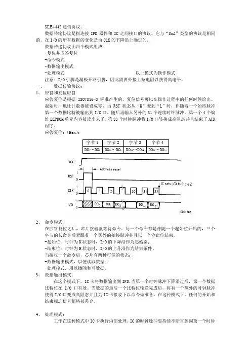
一、数据传输协议:1、应答和复位应答应答复位是根据ISO7816-3标准产生的。
复位信号可以在操作过程中的任何时候给出。
起始时,地址计数器被设成零,当RST状态从“H”变到“L”时,伴随着一个始终脉冲第一个数据比特被输出到I/O口。
随后再输入另外的31个连续时钟脉冲,第一个4个编址EEPROM单元内容被读出来了。
第33个时钟脉冲将I/O口转换成高阻态并且结束了ATR 程序。
应答复位:(Hex):字节1字节2字节3字节4DO7…DO0DO15…DO8DO23…DO16DO31…DO242、命令模式在应答复位之后,芯片接着就等待命令。
每一个命令都是伴随一个起始位开始的,三个字节的长命令后紧跟着一个额外的始终脉冲并且以一个停止位结束。
-起始位:时钟为H状态时,I/O的下降沿作为起始态;-结束位:时钟为H状态时,I/O的上升沿作为结束条件。
当接收一个命令后,芯片有两种可能的状态:-数据输出模式,以便读取数据;-处理模式,用以檫除和写数据。
3、数据输出模式:在这个模式下,IC卡将数据输出到IFD.当第一个时钟脉冲下降沿过后,第一个数据比特位在I/O口有效。
当数据的最后一个比特位输送完成后,将有一个额外的时钟脉冲使得I/O口变成高阻态并且为IC卡接收下以命令做准备。
在这种模式下,任何的开始和结束标志信号都将被丢弃。
4、处理模式:工作在这种模式中IC卡执行内部处理。
IC的时钟脉冲要持续不断直到因第一个时钟下降沿而变成L态的I/O口状态变回高阻态。
在此状态下任何形式的开始和结束标志均视为无效。
SIMATIC 工业软件编程和操作手册法律资讯警告提示系统为了您的人身安全以及避免财产损失,必须注意本手册中的提示。
人身安全的提示用一个警告三角表示,仅与财产损失有关的提示不带警告三角。
警告提示根据危险等级由高到低如下表示。
危险表示如果不采取相应的小心措施,将会导致死亡或者严重的人身伤害。
警告表示如果不采取相应的小心措施,可能导致死亡或者严重的人身伤害。
小心表示如果不采取相应的小心措施,可能导致轻微的人身伤害。
注意表示如果不采取相应的小心措施,可能导致财产损失。
当出现多个危险等级的情况下,每次总是使用最高等级的警告提示。
如果在某个警告提示中带有警告可能导致人身伤害的警告三角,则可能在该警告提示中另外还附带有可能导致财产损失的警告。
合格的专业人员本文件所属的产品/系统只允许由符合各项工作要求的合格人员进行操作。
其操作必须遵照各自附带的文件说明,特别是其中的安全及警告提示。
由于具备相关培训及经验,合格人员可以察觉本产品/系统的风险,并避免可能的危险。
按规定使用 Siemens 产品请注意下列说明:警告Siemens 产品只允许用于目录和相关技术文件中规定的使用情况。
如果要使用其他公司的产品和组件,必须得到 Siemens 推荐和允许。
正确的运输、储存、组装、装配、安装、调试、操作和维护是产品安全、正常运行的前提。
必须保证允许的环境条件。
必须注意相关文件中的提示。
商标所有带有标记符号 ® 的都是 Siemens AG 的注册商标。
本印刷品中的其他符号可能是一些其他商标。
若第三方出于自身目的使用这些商标,将侵害其所有者的权利。
责任免除我们已对印刷品中所述内容与硬件和软件的一致性作过检查。
然而不排除存在偏差的可能性,因此我们不保证印刷品中所述内容与硬件和软件完全一致。
印刷品中的数据都按规定经过检测,必要的修正值包含在下一版本中。
Siemens AG Digital Industries A5E33215622-AMⓅ 11/2022 本公司保留更改的权利Copyright © Siemens AG 2011 - 2022.保留所有权利重要事项本文档的用途本文档中的信息将在组态 (页 49)和编程 (页 116) SIMATIC Safety 故障安全系统方面为您提供支持。
用于ICS4__ / I C S 6__的MT-SICS 标准接口命令集/ 6 22019673 12/12感谢您选择了梅特勒-托利多公司的产品与服务。
梅特勒-托利多公司提供的称重设备/系统具有高品质和高可靠性。
作为称重设备/系统的设计者和生产者,梅特勒-托利多比其他任何人都更了解称重设备/系统如何运行以及如何为您提供最佳的解决方案。
我们的产品和服务,将会伴随您走向成功!我们诚挚的邀请您访问我们的网站:www /productregistrat ion请用一点时间注册您的产品。
通过注册,您将继续获得以下信息:∙产品性能的改进; ∙ 新产品和服务; ∙ 您所购产品的重要通知;目录1 介绍 (4)1.1 命令的标准化 (4)1.2 命令综述 (5)2 数据交换 (6)2.1 命令格式 (6)2.2 应答格式 (7)2.3 程序员提示 (8)2.4 建立通信 (9)2.5 故障查找 (10)3 命令综述 (11)4 0级命令 (15)4.1 综述 (15)4.2 命令描述 (16)5 1级命令 (22)5.1 综述 (22)5.2 命令描述 (22)6 2级命令 (27)6.1 综述 (27)6.2 命令描述 (28)7 3级命令 (51)7.1 综述 (51)7.2 命令描述 (52)8 命令索引 (72)3 12/1222019673-/ 6/ 6 22019673 12/121 介绍在测量重量时,存在对于秤的可读性和最大量程的要求,以及对于从小于一毫克直至几百吨的称量范围的要求。
为了满足这些基本和扩展需求,梅特勒-托利多公司能提供范围广泛的天平和秤。
我们的许多天平和秤都可以集成到复杂的计算机或数据采集系统中。
为了以一种简单的方式把我们的秤集成到客户的系统中,并充分利用它们的能力,大多数秤的功能可根据合适的命令通过数据接口而获得。
1.1命令的标准化所有新上市的梅特勒-托利多装置都支持标准化命令集“梅特勒-托利多标准接口命令集”(MT-SICS );根据装置的功能,命令集分为4个等级:· MT-SICS 的第0级 用于最简单的秤的命令集,例如,称重传感器 · MT-SICS 的第1级 用于标准秤的命令集扩展,即,无集成应用的秤 ·MT-SICS 的第2级 命令集扩展,增加了专门针对一个产品系列的命令 · MT-SICS 的第3级 命令集扩展,增加了专门针对一个产品系列中特定应用的命令这个概念的具体显著特点是,在0级和1级MT-SICS 组合中的命令对于所有秤是完全相同的。
![2.4.6 使用PLCSIM(模拟程序S7是可选软件包)进行测试[共6页]](https://uimg.taocdn.com/c4e3dca67fd5360cbb1adb1f.webp)
PLC 职业技能培训及视频精讲——西门子STEP 7364用块中执行断点测试。
可以单击“”逐个删除断点,或者单击“”删除所有断点。
删除所有断点后,单击“”,即可恢复到RUN 状态。
注意 如果要显示调用顺序,需要在SIMA TIC 管理器中单击菜单栏的“PLC ”→“诊断/设置”→“模块信息”。
如果要查看下一个断点,单击菜单栏的“显示下一个断点”。
光标将跳转到所选择的下一个断点,而无需处理块。
在下载期间,拒绝下载在PLC 中具有断点的块,只有在删除断点后才能下载。
2.4.6 使用PLCSIM(模拟程序S7是可选软件包)进行测试(本程序例在本书配套的光盘里有,打开方法是“My Disc :\ 配套书-S7例子程序\第2章第4节例程\S7PLCSIM ”。
)1.PLC Simulation 概述使用可选择的软件包PLC Simulation (本书简称为“PLCSIM ”),可以在计算机或编程设备(如Power PG )中模拟可编程控制器运行和测试程序。
因为模拟完全由STEP 7软件实现,所以不需要任何S7硬件(CPU 或信号模块)。
使用PLCSIM ,可以测试和维护S7-300/400 CPU 的程序。
PLCSIM 提供简单的用户界面,用于监视和修改在程序中使用的各种参数(例如,用于开、关输入)。
当程序由PLCSIM 处理时,也可以在STEP 7软件中使用各种应用程序。
例如,可以用变量表监视、修改变量及断点测试功能。
专业版的STEP 7包含PLCSIM ,其他版本如果不包含PLCSIM ,可以单独安装。
在安装的过程中使用默认的安装路径将自动嵌入STEP 7中。
PLCSIM 与实际PLC 的区别:① PLCSIM 与实际PLC 实时运行性能不同。
比如PLCSIM 在处理过程映像时是同步的,也就是说过程映像的I/O 会立刻传送到外设的I/O ,又比如在PLCSIM 面板上修改的变量在程序中立刻会生效,无需等待到下一个周期。

Siemens PLC系统软件冗余的说明与实现软件冗余基本信息介绍软件冗余是Siemens实现冗余功能的一种低成本解决方案,可以应用于对主备系统切换时间要求不高的控制系统中。
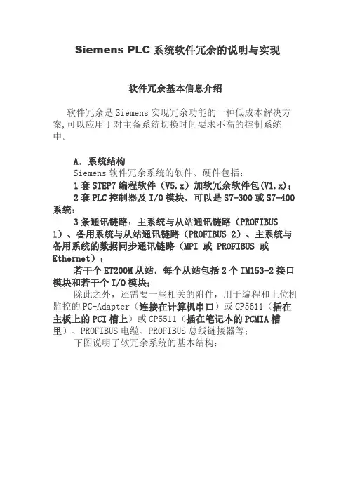
A.系统结构Siemens软件冗余系统的软件、硬件包括:1套STEP7编程软件(V5.x)加软冗余软件包(V1.x);2套PLC控制器及I/O模块,可以是S7-300或S7-400系统;3条通讯链路,主系统与从站通讯链路(PROFIBUS 1)、备用系统与从站通讯链路(PROFIBUS 2)、主系统与备用系统的数据同步通讯链路(MPI 或 PROFIBUS 或Ethernet);若干个ET200M从站,每个从站包括2个IM153-2接口模块和若干个I/O模块;除此之外,还需要一些相关的附件,用于编程和上位机监控的PC-Adapter(连接在计算机串口)或CP5611(插在主板上的PCI槽上)或CP5511(插在笔记本的PCMIA槽里)、PROFIBUS电缆、PROFIBUS总线链接器等;下图说明了软冗余系统的基本结构:图2可以看出,系统是由两套独立的S7-300或S7-400 PLC 系统组成,软冗余能够实现:I.主机架电源、背板总线等冗余;II.PLC处理器冗余;III.PROFIBUS现场总线网络冗余(包括通讯接口、总线接头、总线电缆的冗余);IV.ET200M站的通讯接口模块IM153-2冗余。
软冗余系统由A和B两套PLC控制系统组成。
开始时,A 系统为主,B系统为备用,当主系统A中的任何一个组件出错,控制任务会自动切换到备用系统B当中执行,这时,B系统为主,A系统为备用,这种切换过程是包括电源、CPU、通讯电缆和IM153接口模块的整体切换。
系统运行过程中,即使没有任何组件出错,操作人员也可以通过设定控制字,实现手动的主备系统切换,这种手动切换过程,对于控制系统的软硬件调整,更换,扩容非常有用,即Altering Configuration and Application Program in RUN Mode 。
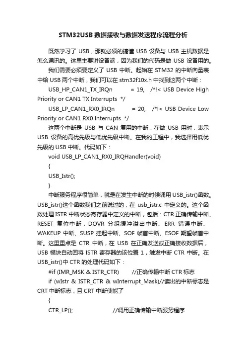
STM32USB数据接收与数据发送程序流程分析既然学习了USB,那就必须的搞懂USB设备与USB主机数据是怎么通讯的。
这里主要讲设备端,因为我们的代码是做USB设备用的。
我们需要必须要定义了USB中断。
起始在STM32的中断向量表中给USB两个中断,我们可以在stm32f10x.h中找到这两个中断:USB_HP_CAN1_TX_IRQn = 19, /*!< USB Device High Priority or CAN1 TX Interrupts */USB_LP_CAN1_RX0_IRQn = 20, /*!< USB Device Low Priority or CAN1 RX0 Interrupts */这两个中断是USB与CAN复用的中断,在做USB用时,表示USB设备的高优先级与低优先级中断。
在我的工程中,我选择用低优先级的USB中断。
代码如下:void USB_LP_CAN1_RX0_IRQHandler(void){USB_Istr();}中断服务程序很简单,就是在发生中断的时候调用USB_istr()函数。
USB_istr()这个函数我们之前说过的,在usb_istr.c中定义的。
这个函数处理ISTR中断状态寄存器中定义的中断,包括:CTR正确传输中断、RESET复位中断,DOVR分组缓冲溢出中断、ERR错误中断、WAKEUP中断、SUSP挂起中断、SOF帧首中断、ESOF期望帧首中断。
这里重点是CTR中断,在USB在正确发送或正确接收数据后,USB模块自动回将ISTR寄存器的该位置1,触发中断CTR中断。
在USB_istr()中CTR的处理代码如下:#if (IMR_MSK & ISTR_CTR) //正确传输中断CTR标志if (wIstr & ISTR_CTR & wInterrupt_Mask)//读出的中断标志是CRT中断标志,且CRT中断使能了{CTR_LP(); //调用正确传输中断服务程序#ifdef CTR_CALLBACKCTR_Callback(); //当定义了CTR_CALLBACK,则调用CTR_Callback,像钩子函数一样,在发生CRT中断时做点什么#endif}首先要解释下 #if (IMR_MSK & ISTR_CTR) 这句话。


城卡数据解包系统使用手册重庆城卡电子技术有限公司目录文件修订记录 (2)1.总体功能描述 (3)2.运行环境 (4)3.文件及文件夹说明 (5)4.软件安装说明 (6)4.1.安装交易数据采集系统Standard。
(6)4.2.操作说明 (8)5.常见错误 (12)5.1.文件目录或备份文件不存在 (12)5.2.重复解包: (12)5.3.其它异常 (13)5.4.卸载软件 (13)文件修订记录版本号生成日期作者修订内容V2.0.0.1 2011-07-27 城卡电子技术有限公司初始版本1.总体功能描述系统采用三层C/S结构,采用主流的C#语言进行开发。
数据解包系统(AUPS2)主要实现数据解包功能:将Standard从采集器中采集到PC中的数据包进行解包。
2.运行环境硬件要求类别基本要求服务器端CPU XEON 2G 内存2G以上;硬盘剩余空间不低于50G;客户端CPU P4 1.8G 内存512M以上;硬盘剩余空间不低于1G;软件要求:类别名称基本环境服务器端操作系统支持Windows2003 32位/64位中文企业版;数据库软件支持SQL Server2000/2005.NET环境.NET Framework2.0客户端操作系统支持WindowsXP/2003.NET环境.NET Framework2.0其它软件MS Excel,Crystal Reports3.文件及文件夹说明1、AUPS2.exe:主执行程序。
2、AUPS2的配置文件Aups2.ini;AUPS2.pdb;AUPS2.vshost.exe4.软件安装说明本软件由VS2005开发,运行前需要安装.NET 2.0运行环境(dotnetfx.exe)。
dotnetfx.exe为.NET框架可重新分发程序包。
安装完成后,在控制面板,添加删除程序中可以看到如下图标:4.1. 安装交易数据采集系统Standard。
运行AUPS2.msi开始安装,如下图所示,进行一步一步安装,直到完成。
ES - SIMATIC Manager -- 项目操作--编译/装载OSPCS 7中OS 项目不能下载时或者OS项目不能激活时需要检查哪些设置?Problems when mapping data blocks with the same nameComplete download of redundant servers in runningoperation in PCS7 V6.0OS 编译时,如何解决如下错误信息:"The number ofparameters for the structured DM variables xxx of type yyydoes not match the number of operator-controlledconnections..."。
当编译OS 时,出现错误消息"The number of externalDM variables in WinCC exceeds the permitted in totalnumber" ?PLC-OS data transfer via the TCP/IP protocol日志文件中警告"*** Warning(s) ***: The structure typeXXXX has been changed since the last compilation. Allassociated structured tags (even other S7 programs) willbe deleted on the OS." 的意思?如何使用模板画面"@PCS7Typicals*.pdl" 来创建块图标(block icon)?编译OS时弹出的如下错误信息"302:3018 - There are process variables whose names are not unique within the project after replacing special characters..." 是什么意思?进行OS下载时,在"Download OS"对话框中会显示什么样的消息?如何清除OS编译时出现的如下错误信息"The number of external DM variables in WinCC exceeds the permitted in total number" ?从ES站下载到OS站的OS项目,为什么不能打开?在PCS7 V5.x与V4.0x中那些分隔符与特殊字符不能使用,在AS/OS传输过程中如何替换?OS在线下载要求?CFC组态的文本和实际OS运行的文本不一致该怎么办?CFC中组态的文本,在进行OS编译时是如何传输到OS项目中的,在组态时特变需要注意什么?在SIMATIC PCS 7 V5.x 中重新装载服务器和MultiClient 在SIMATIC PCS 7 V6.x 中更新OS Runtime 数据所必须执行的步骤如果在PCS7 V7.0中,由于WinCC项目无法打开而导致编译OS进程被中断该怎么办?为什么WinCC 变量具有“写保护”状态而不能编辑、删除或移动?功能块重构之后的OS 修改编译为什么不能通过OS编译将S7结构单元或UDT 传送到WinCC?为什么无论OS站的运行系统是否被激活,都无法从SIMATIC PCS 7 ES 中执行增量下载操作?在工程师站测试OS项目时的警告信息如何清除错误消息“Download (310:88)”?如何更正错误消息“OS is currently being loaded from another ES”?从版本PCS 7 V6.1起,如何生成和加载服务器数据包(服务器包)?在重新装载ES中的OS项目到服务器之后,如何清除不明确出错消息和异常中止?编译OS项目时,如何清除transfer.log文件中的内部错误15500 ?为什么装载delta时会出现错误信息“FileCopyError....WinCC6.0_Project\GraCS\Default.pdd”,以及“Default.pdd”文件的作用是什么?为什么在编译OS数据文件和加载OS数据文件后,PCS 7V6.0 SP3 + SP3 Postfixes不再更新文本?如何清除出错消息“*** Error(s) ***: Error while requestingmessages from the STEP 7 message server....”?当编译OS项目时,如何清除出错消息“Internal error:transfer of process variables has been aborted. Errornumber: 15424”?如何清除OS编译时出现的错误消息“No DM variable canbe created for a symbol without a name”?为什么不能通过网络载入一个项目?PCS 7中OS 项目不能下载时或者OS项目不能激活时需要检查哪些设置?显示订货号配置说明:为了确保OS项目成功下载并激活,此条目给出了所需要做的设置。
μC/OS-II在S3C44BOX处理器上的移植摘要:介绍实时操作系统μC/OS-II的特点和内核结构,给出μC/OS-II在Samsung嵌入式S3C44BOXARM7微处理器上的移植的步骤及详细相关代码,同时阐述μC/OS—II在应用中应注意的问题。
μC/OS-II功能,支持56个用户任务,其内核为占先式,支持信号量、邮箱、队列等多种常用的进程间通信机制,现已成功应用到众多商业嵌入式系统中,是一个成熟稳定的实时内核。
与大多商用RTOS不同的是,μC/OS—II公开所有的源代码,90%的代码使用标准的ANSI C语言书写,程序可读性强、移植性好;同时它可免费获得,即使商业应用也只收取少量的许可费用。
因此,对μC/OS—II实时操作系统的学习研究、开发、应用具有重要意义。
Samsung S3C44B0X微处理器是三星专为手持设备和其它嵌入式应用提供的高性价比的微控制器解决方案。
它使用ARM的16位/32位RISC结构,内核是ARM7TDMI,工作在66M,片上集成了以下部件:8K Cache、外部存储器控制器、LCD控制器、4个DMA通道、2个UART、1个多主I2C总线控制器、1个I2C总线控制器,以及5通道PWM定时器和1个内部定时器、8通道12位ADC等,能够与常用的设备实现无缝连接,功能。
目前,国内应用较为广泛。
1 μC/OS—II实时操作系统结构ﻭ图1说明了μC/OS—II的软硬件体系结构.应用程序处于整个系统的顶层,每个任务都可以认为自已独占了CPU,因而可以设计成为一个无限循环.μC/O S-II处理器无关的代码提供了μC/OS-II的系统服务,应用程序可以使用这些API函数进行内存管理、任务间通信及创建、删除任务等。
大部分的μC/OS-II代码是使用ANSIC语言书写的,因此μC/OS-II的可移植性好,然而仍需要使用C和汇编语言写一些处理器相关代码。
μC/OS—II的移植需要满足以下要求:①处理器的C编译器可以产生可重入代码;ﻭ②可以使用C调用进入和退出临界区代码;ﻭ③处理器必须支持硬件中断,并且需要一个定时中断源;ﻭ④处理器需要能够容纳一定数据的硬件堆栈;ﻭ⑤处理器需要有能够在CPU寄存器与内核和堆栈交换数据的指令.ﻭS3C44B0X处理器完全满足上述要求。
SIMATIC 用于SIMATIC S7 / M7 / C7的STEP 7 V5.4 SP3.1中文编程软件
安装与使用注意事项 该注意事项中包含的信息相对于其他文档来说是最新的。请仔细阅读,此文本中包含了有关带Service Pack 3.1的STEP 7 V5.4的安装与使用信息。
请注意,对于A4格式,所要打印文件的左右边距都设置成25mm。
目录 安装注意事项 1 发货清单 2 硬件要求 3 软件要求 3.1 运行环境 3.2 存储器要求 3.3 与其它软件产品的兼容性 3.3.1 使用其它软件产品时的网络设置
3.3.2 与已安装的S7容错系统的交互操作 3.4 在线文档 3.5 从一个较早的STEP 7版本升级
3.5.1 STEP 7 V5.4 SP3.1升级版 4 安装 4.1 安装STEP 7 V5.4 SP3.1
4.2 STEP 7 V5.4 SP3.1许可证密钥 4.3 删除含SP3.1的STEP 7 V5.4 4.4 安装时的其它注意事项 4.4.1 使用滚轮鼠标 4.4.2 使用PC/PG通讯卡时的注意事项 使用注意事项(版本注释) 5 新版软件的新特性和所作的修改 6 组态和操作软件时的注意事项 6.1 STEP 7如何满足IEC标准 6.2 常规注意事项 6.3 使用网络驱动器 6.4 多用户操作 6.5 多重项目
6.6 交换不同版本的STEP 7 6.7 库文件和实例项目 6.8 SIMATIC管理器 6.9 口令保护 6.10 使用符号名(符号的大写和小写)
6.11 硬件配置(中央机架) 6.12 硬件配置(PROFIBUS DP) 6.13 硬件配置(PROFINET IO) 6.14 冗余I/O: 通道间隔冗余 6.15 硬件诊断 6.16 组态连接
6.17 MPI / PROFIBUS网络设置
6.18 SIMATIC M7 6.19 梯形图、功能块图、语句表和参考数据 6.20 消息组态 6.21 翻译文本 6.22 管理多语言文本
Rev. 0.2 7/13Copyright © 2013 by Silicon LaboratoriesAN626AN626PACKET HANDLER OPERATION FOR Si446X RFICS
1. IntroductionThis application note discusses the operation of the Packet Handler (PH) on the Si446x family of RFICs. Details ofoperation in both TX mode and RX mode are provided. The purpose of this application note is to expand upon theinformation available in the data sheets for Si446x devices. This application note does not discuss direct mode orraw data mode (as may be required by legacy systems with non-standard packet structures). A thoroughunderstanding of the topics discussed within this application note will be helpful in construction of a typical packetstructure such as that shown in Figure1.
Figure1.General Packet StructureIn order to completely specify the structure of the packet, it is necessary to configure the Preamble, Sync Word,and Data fields. Configuration of these fields is provided by four groups of properties accessible through the API:
Property Group 0x10xx=Preamble ConfigurationProperty Group 0x11xx=Sync Word ConfigurationProperty Group 0x12xx=Packet Field ConfigurationProperty Group 0x30xx=Match (Header Check) ConfigurationAlthough the PH itself is concerned only with configuration of the Packet Fields (property group 0x12xx), all fourproperty groups are discussed within this document; a thorough understanding of configuration of these groups isrequired to construct a desired packet structure.
It is assumed that the user has a basic familiarity with the API for the Si446x family of RFICs. All configurations ofthe PH discussed within this application note are accomplished through the use of published API calls.
1-255 Bytes1-4 Bytes0, 2, or 4 BytesSync WordPreambleCRC Field 1 (opt)Field 1Header or DataField 2 (opt)Pkt Length or DataCRC Field 2 (opt)Field 3 (opt)DataCRC Field 3 (opt)Field 4 (opt)DataCRC Field 4 (opt)Field 5 (opt)DataCRC Field 5 (opt)ConfigConfig0, 2, or 4 BytesConfig0, 2, or 4 Bytes0, 2, or 4 Bytes0, 2, or 4 BytesConfigConfigAN626
2Rev. 0.22. Packet Handler OverviewThe Si446x family of chips contains circuit functionality known as the automatic Packet Handler (PH). The purposeof the PH is to automatically perform basic packet structure construction (in TX mode) or deconstruction (in RXmode), without the need for MCU control or intervention. The usual fields needed for packet generation (such asPreamble and Sync Word) normally change infrequently and can therefore be stored in registers. Automaticallyadding these fields to the Payload data greatly reduces the required computational power of the MCU, allowing useof a less-complex (i.e., cheaper) MCU.
The PH has little benefit unless the chip is also operated in FIFO mode (as opposed to Direct mode where the bitsof the transmit or receive data stream are processed in real-time on a physical input or output pin). Therefore,operation of the chip in FIFO mode is assumed throughout this document, unless noted otherwise.
The functionality of the PH may be enabled or disabled in RX mode. Enabling/disabling of the PH functionality isprovided in Property 0x1206 PKT_CONFIG1 by the PH_RX_DISABLE bit D6. However, if the PH is disabled thereceiver may only be operated in Direct mode; operation in FIFO mode is not possible. The PH remains enabled atall times in TX mode.
Figure2.Property 0x1206 PKT_CONFIG1, General Packet Configuration BitsThe functionality of the PH includes the following:Detection/validation of Preamble quality in RX mode (PREAMBLE_VALID signal)Detection of Sync word in RX mode (SYNC_OK signal)Detection of valid packets in RX mode (PKT_VALID signal)Detection of CRC errors in RX mode (CRC_ERR signal)Data de-whitening and/or Manchester decoding (if enabled) in RX modeMatch/Header checking in RX modeStorage of Data Field bytes into FIFO memory in RX modeConstruction of Preamble field in TX modeConstruction of Sync field in TX modeConstruction of Data Field from FIFO memory in TX modeConstruction of CRC field (if enabled) in TX modeData whitening and/or Manchester encoding (if enabled) in TX modeAN626
Rev. 0.233. Packet Handler in TX ModeIn TX mode, operation of the PH has no meaning unless the chip is also operated in FIFO mode. This is self-evident; if the bits of the transmit data stream are provided by the host MCU in real-time on a physical input pin, theentire structure of the transmit packet is already determined and there is no additional functionality for the PH toprovide. Thus the true benefit of the PH in TX mode is only realized when the Data Field bytes are programmedinto FIFO memory, and the remainder of the packet structure is automatically constructed using the PHfunctionality. The PH functionality always remains enabled in TX mode; there is no enable/disable property for thePH in TX mode as there is in RX mode.