Kinetic Modeling of the Methanol to Olefins Process. 2.
- 格式:pdf
- 大小:166.25 KB
- 文档页数:10

煤制烯烃副产混合碳五的综合利用探讨煤制烯烃副产混合碳五的综合利用探讨摘要:煤制烯烃技术是替代石油生产低烯烃的新型工艺路线,混合碳五是煤制烯烃重要的副产品,和石油化工副产混合碳五既有相似之处也存在差异,本文借鉴石油化工副产碳五馏分的综合利用技术,同时针对煤基甲醇制烯烃副产混合碳五馏分的特点,就甲醇制烯烃副产混合碳五馏分的综合利用进行探讨,指出了甲醇制烯烃副产混合碳五馏分利用的关键是其单烯烃组分的综合利用。
关键词:混合碳五加氢 TAME MTODiscussion on Comprehensive Utilization of C5 Fraction from Coal to Olefins ProcessGuorong He(Shenhua Baotou Coal Chemical Co. Ltd, Baotou 014010, China)Abstract: Coal-to-olefins, as a potential method instead of conventional oil route, has received wide attention in the past years. Mixed C5 fractions produced in methanol-to-olefins(MTO) process were commented in this paper that provided utilization means for mixed C5 fractions, and comprehensive utilization for C5 fration will bring the best economics for MTO plant by increasing the value of C5 byproducts.Key words: MTO TAME C5 fration hydrogenation神华包头煤制烯烃项目是以煤为原料,通过煤气化制甲醇、甲醇转化制烯烃、烯烃聚合工艺路线生产聚烯烃的世界首套、全球最大、国家级煤制烯烃示范工程。
第50卷第1期2021年1月辽宁化工Liaoning Chemicdl IndustryVol.50,No.1January,2021用铁炭微电B-Fenton试剂处理制药废水王海棠(江苏省盐城市环境保护新技术研究中心,江苏盐城224000)摘要:采用铁炭微电解-Fenton试剂处理制药废水设计处理水量:物化预处理2m'h\生化处理3mUJ。
运行结果表明.该工艺处理效果良好,出水pH6~9,COD^SOO mgL SS^400mgl/1, NH,-N«50mg L'.甲苯WO.lmgl",氟化物^lOmg-L三乙胺W1.08mg・I「,DMF^0.45mg L1.盐分W5000mg・L",出水水质优于设计指标要求:关键词:铁炭微电解;Fenton试剂;制药废水中图分类号:TQ08514文献标识码:A文章编号:1004-0935(2021)01-0075-04左氟沙星合成工艺经过氯化、缩合、氟化、水解、竣酸、酰氯化、讎化、胺化、环合等工序,生产废水主要来自氟化工序、环合工序、醛化匸序、缩合丁序和水解工序,制药废水,尤其是采用化工合成制药废水,具有水质成分复杂、生物降解程度低、有毒有害物质含量高的特点,制药废水的有效治理是我国工业废水处理的难点和重点之一“。
不同品种制药废水及不同环节产生的废水成分不同,处理方式亦不同。
传统的活性污泥处理方法治理制药废水存在处理效率低下、系统稳定性差及微生物易受毒害性等特点叫1废水处理工艺选择1.1废水特点及分类本项目废水水质特点如下:1)废水中盐分浓度高。
2)含有大量环丁砚、DMF等难降解有机物。
3)高浓度含氟废水,会对微生物有抑制作用,腐蚀性强。
根据废水特点,将本项目废水分为高含盐废水、高浓度含氟废水、高浓度有机废水、低浓度废水四类,进行分类收集,分质处理。
1.2工艺选择1)废水中的盐浓度较高时,生化处理难以运行。
高含盐废水处理方法主要有驯化处理、稀释进水盐度、蒸发浓缩,在盐度大于2g-U'时,蒸发浓缩除盐是最经济、最有效的可行办法。
M T O技术的发展情况及工艺简介张善全(神华包头煤化工有限公司,内蒙古包头 014010) 摘 要:M TO是Methanol to Olefins的缩写,即甲醇制烯烃。
目前,世界上石油供应日趋紧张,由甲醇制取烯烃的技术受到普遍关注,国际上一些著名的石油和化学公司都投入了大量资金进行研究。
关键词:M TO;FCC(催化裂化);反应器;再生器;催化剂1 MT O技术的发展情况1.1 国外研发进展情况甲醇制烯烃技术的关键在于催化剂活性和选择性及相应的工艺流程设计,其研究工作主要集中在催化剂的筛选和制备。
1.1.1 美孚公司美孚公司(Mobil)提出了一种使用ZSM-5催化剂,在列管式反应器中进行甲醇转化制烯烃的工艺流程,并进行过9个月的中试,试验规模为100桶/天。
在工艺过程中,甲醇扩散到催化剂孔中进行反应,首先生成二甲醚,然后生成乙烯,反应继续进行,生成丙烯、丁烯和高级烯烃,也可生成二聚物和环状化合物,以碳选择性为基础,乙烯收率可达60%(W),烯烃总收率可达80%(W),大体相当于采用常规石脑油/粗柴油管式炉裂解法收率的两倍,但催化剂的寿命尚不理想。
1.1.2 巴斯夫公司巴斯夫公司(BASF)采用沸石催化剂,在德国路德维希港建立了一套日消耗30吨甲醇的中试装置。
其反应温度为300~450℃,压力为0.1~0.5MPa,用各种沸石做催化剂,初步试验结果是C2-C4烯烃的重量收率为50~60%,收率太低。
1.1.3 环球油品公司环球油品公司(UOP)筛选出的催化剂称作MT O-100,M TO-100是联碳公司开发的SAPO -34与一系列专门选择的黏合剂材料之结合体。
SAPO-34是M TO-100催化剂的基体,于20世纪80年代由U nion Carbide分子筛部开发,主要化学成分包括硅(Si)、铝(Al)、磷(P)、氧(O)等元素。
它具有适宜的内孔道结构尺寸和固体酸性强度,能够尽量减少反应初期生成的烯烃发生齐聚反应生成大分子烃类,从而提高目标产物--烯烃的选择性。
化工进展Chemical Industry and Engineering Progress2023 年第 42 卷第 3 期逆水煤气变换反应研究进展王晓月,张伟敏,姚正阳,郭晓宏,李聪明(太原理工大学省部共建煤基能源清洁高效利用国家重点实验室,山西 太原 030024)摘要:逆水煤气变换(RWGS )反应是将二氧化碳(CO 2)加氢转化为甲醇、低碳烯烃、芳烃以及汽油等高附加值化学品和燃料的关键步骤,对于实现CO 2资源化利用具有重要意义。
本文综述了近年来RWGS 反应的研究进展,包括RWGS 反应热力学分析、催化机理、可选择的催化剂种类以及提升催化剂性能策略等方面。
文章从热力学角度分析,RWGS 反应在高温下有利,而低温下存在甲烷化竞争反应。
RWGS 反应机理主要包括氧化还原机理以及缔合机理,其中缔合机理包括甲酸盐路径和羧酸盐路径等。
相比于其他催化体系,负载型金属催化剂展现出较优异的RWGS 反应性能。
另外,通过添加碱金属助剂、形成双金属合金以及选择合适载体和减小金属颗粒尺寸以优化金属-载体相互作用等手段可实现低温高效稳定的RWGS 反应催化剂的设计开发。
关键词:逆水煤气变换反应;二氧化碳;一氧化碳;热力学;催化剂中图分类号:TQ073 文献标志码:A 文章编号:1000-6613(2023)03-1583-12Research progress of reverse water gas shift reactionWANG Xiaoyue ,ZHANG Weimin ,YAO Zhengyang ,GUO Xiaohong ,LI Congming(State Key Laboratory of Clean and Efficient Coal Utilization, Taiyuan University of Technology, Taiyuan 030024, Shanxi, China)Abstract: Reverse water gas conversion (RWGS) reaction is a key step in the catalytic hydrogenation ofcarbon dioxide (CO 2) to high value-added chemicals and fuels such as methanol, light olefins, aromatics and gasoline, which is of great significance for the utilization of CO 2. This review summarizes the research progress of RWGS reaction in recent years, including thermodynamic analysis of RWGS reaction, catalytic mechanisms, selective catalysts and strategies to improve the performance of catalysts. From the perspective of thermodynamics, RWGS reaction is favorable at high temperature, as methanation reaction emerges at low temperature. The mechanisms of RWGS reaction mainly consist of redox mechanism and association mechanism, and the latter further contains a formate route and/or carboxylate route. Compared with other catalyst system, supported metal catalysts commonly exhibit a superior RWGS reaction performance. In addition, the rational design of RWGS reaction catalysts with high reactivity and durability could be realized by adding alkali metal additives, forming bimetallic alloy as well as modulating the metal-support interaction via selecting a good support or reducing the metal particle size.Keywords: reverse water gas shift reaction; carbon dioxide; carbon monoxide; thermodynamics; catalyst综述与专论DOI :10.16085/j.issn.1000-6613.2022-0816收稿日期:2022-05-05;修改稿日期:2022-07-13。
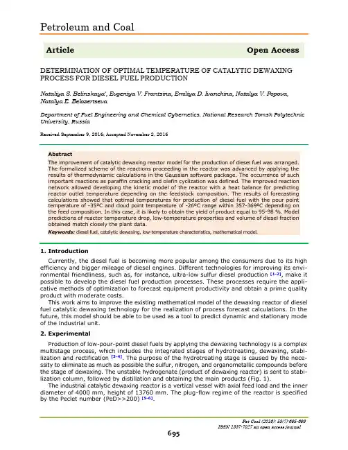
Petroleum and CoalArticle Open Access DETERMINATION OF OPTIMAL TEMPERATURE OF CATALYTIC DEWAXING PROCESS FOR DIESEL FUEL PRODUCTIONNataliya S. Belinskaya*, Evgeniya V. Frantsina, Emiliya D. Ivanchina, Natalya V. Popova, Natalya E. BelozertsevaDepartment of Fuel Engineering and Chemical Cybernetics, National Research Tomsk Polytechnic University, RussiaReceived September 9, 2016; Accepted November 2, 2016AbstractThe improvement of catalytic dewaxing reactor model for the production of diesel fuel was arranged.The formalized scheme of the reactions proceeding in the reactor was advanced by applying the results of thermodynamic calculations in the Gaussian software package. The occurrence of such important reactions as paraffin cracking and olefin cyclization was defined. The improved reaction network allowed developing the kinetic model of the reactor with a heat balance for predicting reactor outlet temperature depending on the feedstock composition. The results of forecasting calculations showed that optimal temperatures for production of diesel fuel with the pour point temperature of -35ºC and cloud point temperature of -26ºC range within 357-369ºC depending on the feed composition. In this case, it is likely to obtain the yield of product equal to 95-98 %. Model predictions of reactor temperature drop, low-temperature properties and volume of diesel fraction obtained match closely the plant data.Keywords: diesel fuel, catalytic dewaxing, low-temperature characteristics, mathematical model.1. IntroductionCurrently, the diesel fuel is becoming more popular among the consumers due to its high efficiency and bigger mileage of diesel engines. Different technologies for improving its envi-ronmental friendliness, such as, for instance, ultra-low sulfur diesel production [1-2], make it possible to develop the diesel fuel production processes. These processes require the appli-cative methods of optimization to forecast equipment productivity and obtain a prime quality product with moderate costs.This work aims to improve the existing mathematical model of the dewaxing reactor of diesel fuel catalytic dewaxing technology for the realization of process forecast calculations. In the future, this model should be able to be used as a tool to predict dynamic and stationary mode of the industrial unit.2. ExperimentalProduction of low-pour-point diesel fuels by applying the dewaxing technology is a complex multistage process, which includes the integrated stages of hydrotreating, dewaxing, stabi-lization and rectification [3-4]. The purpose of the hydrotreating stage is caused by the nece-ssity to eliminate as much as possible the sulfur, nitrogen, and organometallic compounds before the stage of dewaxing. The unstable hydrogenate (product of dewaxing reactor) is sent to stabi-lization column, followed by distillation and obtaining the main products (Fig. 1).The industrial catalytic dewaxing reactor is a vertical vessel with axial feed load and the inner diameter of 4000 mm, height of 13760 mm. The plug-flow regime of the reactor is specified by the Peclet number (PeD>>200) [5-6].Fig. 1. Industrial diesel fuels catalytic dewaxing unitThe method of mathematical modeling, which is widely applied for the study of petroleum and gas treatment processes [7-15], is used in this research. The composition of the feedstock entering the reactor is not permanent due to the various ratios of light and heavy fractions at the unit (Tab. 1). Reactor model should be relevant to the feed hydrocarbon composition in order to properly forecast the reactor operation.Table 1. Hydrocarbon composition of the reactor feedstock27.02.2015 27.0 23.1 16.6 33.318.04.2015 28.2 20.0 17.3 34.623.12.2015 26.8 24.7 16.1 32.320.05.2015 26.7 26.3 15.7 31.305.04.2014 26.8 27.4 15.3 30.611.12.2012 26.5 28.7 14.9 29.826.10.2015 26.3 29.3 14.8 29.6According to the previous studies and developed model [3-4], the formalized reaction scheme involved the main reactions of unbranched long-chain paraffin (C10-C27) hydro-cracking, C5-C9 paraffin dehydrogenation, isomerization of olefins to iso-paraffins followed by cyclization to naphthenes. Also, the reactions of coke formation from aromatics were pre-sented. The improved reaction network (Fig. 2) has advantages over the former scheme which include: integration of long- and short-chain unbranched paraffin into the individual group, the process of cracking of unbranched paraffin into the light gasses (C1-C4), and cyclization of olefins directly into naphthenes.Fig. 2. Formalized scheme of catalytic dewaxing reactionsThe reconsidered reaction network was developed through the thermodynamic parameters with the use of Gaussian software package (Tab. 2). The advanced scheme both gives moreextended knowledge about the processes occurring in the reactor and simplifies its kinetic model [16-17].Table 2. Thermodynamic parameters of the main reactionsСn Н2n +2 Сn Н2n +H 2 133.38 148.7636.98 Olefin cyclization Сn Н2n (naphthene) Сn Н2n (olefin) 30.31 95.13-31.33Before the development of reactor kinetic model and determination of parameters, it had been admitted that the reactor is quasi-homogeneous. In compliance with accepted allowance, the reactions rates of catalytic dewaxing process were represented according to the law of mass action.The system of first-order equations of a kinetic model for each hydrocarbon group is given in Tab. 3. The concentrations of responding compounds are given as C 1-C 10, the rates of reactions accord to the reactions constants in Fig. 2.Table 3. Kinetic model of catalytic dewaxing reactorNormal paraffins1116dC W W W d τ-=-+- Iso-paraffins222dC W W d τ-=+ Naphthenes33344dC W W W W d τ--=+-+ Aromatic compounds4445dC W W W d τ-=-- Olefins5112233dC W W W W W W d τ---=--+-+ Coke65dC W d τ= Hydrocarbon gas76dC W d τ= Hydrogen 8112244533dC W W W W W W W d τ---=--++⋅-⋅+To predict the temperature drop along the reactor at different residence time, and to compute the temperature inside the catalyst bed the reactor heat balance was developed on the basis of the kinetic model. The temperature along the reactor was calculated via the following formula: Cp W Q d dT Cp r c r c ⋅⋅=⋅⋅∑ρτρ)( (1)The forecasting of the reactor for diesel fuel production, including the accurate computation of products yield, pour-point temperature, cloud point temperature and cold filter plugging point temperature, requires the optimization due to the fact that the feedstock compositionand operating parameters (flow rates, temperature, pressure) influence on the performance of the unit.3. Results and discussionThe results of process forecast in case of various unbranched paraffin content are presented below in Tab. 4 and Tab. 5. Also, the optimal temperature for feed flow rate increasing from 300 to 340 m3/h was determined.Table 4. Temperature regimes of the reactor with the unbranched paraffins content 14%wt.300 356 95.3 -25 -34 357 95.2 -26 -35 359 94.9 -27 -36320 358 95.6 -25 -34 361 95.2 -27 -36 363 94.9 -27 -36340 361 95.7 -25 -34 362 95.5 -26 -35 363 95.4 -27 -36*Product includes diesel fractions and stable naphtha.Table 5. Temperature regimes of the reactor with the unbranched content 20%wt.300 356 97.9 -25 -34 359 97.7 -26 -35 363 97.5 -27 -36320 361 97.9 -25 -34 364 97.8 -26 -35 368 97.6 -27 -36340 364 98.0 -25 -34 369 97.9 -26 -35 371 97.8 -27 -36Thus, in the case of unbranched paraffin content equal to 14 wt.%, under the increase in feed flow rate from 300 to 340 m3/h the optimal temperature for the process rises from 357 to 362ºC correspondingly. It should be noticed, that at the optimal values of temperature the pour point and cloud point temperatures achieve the values of -35ºC and -26ºC respectively.In the case of unbranched paraffin content equal to 20 wt.%, under the increase in feed flow rate from 300 to 340 m3/h, the optimal temperature for the process rises from 359 to 369ºC correspondingly. The values of pour point and cloud point temperatures achieve the values of -35 and -26ºC respectively.Also, applying the reactor mathematical model and heat balance, it was revealed that the temperature drop along the reactor varies from 10 to 12ºC which corresponds to the project unit data.4. ConclusionsIn this study on the improvement of mathematical reactor model of the catalytic dewaxing process the new approach to the reactions occurring during the process was performed. The recon-sidered reaction scheme implies the processes of long- and short-branched paraffin cracking and cyclization of olefins.Based on the advanced reaction network proceeding in dewaxing reactor, the mathematical model of the catalytic dewaxing reactor was improved and developed. It involves kinetic model and further heat balance calculation; according to later the temperature drop in the reactor, equal to 10-12ºC, was computed and corresponds to project unit data.The forecasting of the reactor with the implementation of updated model was performed, depending on the various hydrocarbon composition of the feedstock entered the unit. The revealed trends allowed establishing the optimal temperatures inside the reactor for efficient apparatus performance, which values range within the interval of 357-362ºC (unbranched paraffin content in the feedstock is 14 %) and 359-369ºC (unbranched paraffin content in the feedstock is 20 %) for changing feed flow rate from 300 to 340 m3/h.At this point, it is likely to produce the diesel fuel with pour-point temperature of -35ºC and cloud point temperature of -26ºC, in quantity of 95.3-95.4 % and 97.8-97.9 %, which is requi-red at industrial dewaxing units. There is no point in a further increase of the temperature as this likely to result in catalyst deactivation and decreasing selectivity of the process with a higher yield of poor gasses.SymbolsPeD diffusion Peclet number;ΔH av the average value of change in enthalpy, kJ/mole;ΔS av the average value of change in entropy, kJ/mole∙K;ΔG av the average value of change in Gibbs free energy, kJ/mole;Q c.r.the amount of the heat liberated or absorbed during the chemical reaction, J/mole; W c.r.chemical reaction rate, s-1;C p flow heat capacity, J/Mole∙K;ρ flow density, kg/m3.References[1] Antony S, Abdulazeem M, Mohan SR. Catal. Today. 2010, 153 (1-2): 1-68.[2] Seung-Woo L, Son-Ki I. Fuel. 2014, 134: 237-243.[3] Belinskaya N, Ivanchina E, Ivashkina E, Frantsina E and Silko G. IOP Conf. Ser.: EarthEnviron. Sci. 2014; 21, 012030.[4] Belinskaya NS. Pet. Coal. 2016; 58(1): 126-134.[5] Hayes RE, Mmbaga JP. Introduction to Chemical Reactor Analysis Second Edition, CRCPress, Taylor & Francis Group, 2013; 528 p.[6] Ranade VV. Computational flow modeling for chemical reactor engineering: Academic Press,2002, p. 42-43.[7] Zagoruiko AN, Belyi AS, Smolikov MD, Noskov AS. Catal.Today. 2014; 220-222: 168-177.[8] Vorobev A, Zikanov O, Mohanty P. J. Therm. Spray Technol. 2008; 17 (5-6): 956-965.[9] Dolganova IO, Ivashkina EN, Ivanchina ED, Vasyuchka K. Pet. Coal. 2016, 52(2): 135-142.[10] Chuzlov VA, Molotov KV. Pet. Coal. 2016; 58(1): 47-55.[11] Nguyen TS, Tayakout-Fayolle M, Ropars M, Geantet C. Chem. Eng. Sci. 2013; 94: 214-223.[12] Kirgina M, Sviridova E, Sakhnevich B, Chekantsev N, Ivanchina E. IOP Conf. Ser.: Mater.Sci. Eng. 2015; 93(1): 012014[13] Khlebnikova E, Dolganova I, Ivashkina E, Koshkin S. MATEC Web of Conferences. 6thInternational Conference on Chemistry and Chemical Process, ICCCP 2016 49, 2016; Article number 1001[14] Nazarova GY, Burumbaeva GR, Shafran T A, Svarovskii AY. Pet. Coal. 2016; 58 (1): 76-82.[15] Nazarova G, Ivashkina E, Ivanchina E, Kiseleva S, Stebeneva V. IOP Conference Series:Earth and Environmental Science, 2015, 27 (1): 1-7.[16] Erdal A, Ayse DC, Hasan S, Yaman A, Ummuhan C, Gamze I, Murat E. Comput. Chem. Eng.2015; 82: 44-54.[17] Afanasiev IP, Lebedev BL, Talalaev SU, Ishmurzin AV. Petr. Ref. and Petrochem. 2014; 4:27-29.。
SAPO-34分子筛粒径的控制方法刘志玲;张伟;张媛;张菊【摘要】SAPO-34分子筛具有独特的骨架结构,应用于甲醇制低碳烯烃反应时速率较快且不易堵塞.小晶粒SAPO-34分子筛可有效缓解产物聚合结焦,提高催化剂寿命,但通过简单的合成方法得到粒径小于100 nm的SAPO-34纳米颗粒非常困难.综述影响SAPO-34分子筛粒径的因素,通过选择合适的材料,老化和结晶条件,达到有效控制SAPO-34分子筛粒径的目的.以拟薄水铝石为铝源,液态硅为硅源,采用在水热体系中溶解度较高的四乙基氢氧化铵为模板剂,通过适当延长陈化时间和缩短晶化时间,较容易得到粒径较小的SAPO-34分子筛.【期刊名称】《工业催化》【年(卷),期】2016(024)006【总页数】5页(P14-18)【关键词】催化剂工程;SAPO-34分子筛;粒径;控制方法【作者】刘志玲;张伟;张媛;张菊【作者单位】陕西延长石油(集团)有限责任公司,陕西西安710075;陕西延长石油(集团)有限责任公司,陕西西安710075;陕西延长石油(集团)有限责任公司,陕西西安710075;陕西延长石油(集团)有限责任公司,陕西西安710075【正文语种】中文【中图分类】TQ426.6;TQ424.25综述与展望CLC number:TQ426.6;TQ424.25 Document code: A Article ID: 1008-1143(2016)06-0014-05沸石分子筛材料的应用大多需要精确控制晶型和粒径[1-3],其催化、吸附或依赖于扩散的其他反应均与分子筛颗粒粒径和晶型相关,晶体形貌会显著影响性能和应用[4-6]。
如TS-1型钛硅分子筛对酚类羟基化反应有较好的催化作用,但粒径大于10 μm时催化活性较差[7]。
产物烯烃在孔道中积炭结焦是甲醇制低碳烯烃评价反应中的首要问题。
而SAPO-34分子筛的粒径减小后,可以缩短催化剂内孔道长度,利于低碳烯烃产物的扩散,有效缓解其聚合结焦,延长催化剂寿命。
MTO烯烃分离概述MTO(Methanol-to-Olefins)是一种将甲醇转化为烯烃的技术,通过催化剂的作用,将甲醇在高温下进行裂解,生成一系列烯烃产品。
烯烃是一类重要的化工原料,在石化、塑料、橡胶等领域有广泛的应用。
MTO烯烃分离是指将MTO反应产生的混合气体中的烯烃分离出来,以便进一步进行加工和利用。
MTO烯烃分离的原理MTO烯烃分离的原理主要基于烯烃与其他成分的物理性质差异。
烯烃具有较低的沸点和较高的相对分子质量,因此可以通过调节温度和压力来实现对烯烃的分离。
常用的分离方法包括冷凝、吸附、蒸馏等。
冷凝分离冷凝分离是将混合气体通过降温使其中的烯烃冷凝成液体,然后通过液体和气体的分离来获得纯净的烯烃产品。
冷凝分离的关键是选择合适的冷凝剂和控制温度。
常用的冷凝剂有水、乙二醇等。
冷凝分离的优点是操作简单、成本低,但对于含有低沸点的烯烃来说,冷凝分离效果不理想。
吸附分离吸附分离是利用吸附剂对混合气体中的烯烃进行吸附,通过控制吸附剂的选择和温度,使吸附剂上的烯烃得以解吸,从而实现烯烃的分离。
吸附分离的关键是选择合适的吸附剂和控制吸附-解吸的条件。
常用的吸附剂有沸石、活性炭等。
吸附分离的优点是分离效果好、适用于各种烯烃,但操作复杂、成本较高。
蒸馏分离蒸馏分离是将混合气体通过蒸馏塔进行分馏,根据烯烃和其他成分的沸点差异,将烯烃从混合气体中分离出来。
蒸馏分离的关键是选择合适的塔型和控制温度、压力。
蒸馏分离的优点是操作简单、适用于各种烯烃,但设备投资大、能耗较高。
MTO烯烃分离的工艺流程MTO烯烃分离的工艺流程通常包括冷凝分离、吸附分离和蒸馏分离等步骤。
冷凝分离1.将MTO反应产生的混合气体经过冷凝器进行冷却,使其中的烯烃冷凝成液体。
2.冷凝液经过分离器,将液体烯烃和气体分离。
3.分离得到的液体烯烃可以直接作为产品或进一步进行后续处理。
吸附分离1.将MTO反应产生的混合气体经过预处理器,去除其中的杂质。
2.混合气体进入吸附塔,通过控制温度和压力,使吸附剂上的烯烃得以吸附。
甲醇制烯烃工艺流程设计与催化剂评价一、引言甲醇制烯烃是一种重要的化学工艺,可以通过催化剂的作用将甲醇转化为烯烃类化合物,具有广泛的应用前景。
本文将就甲醇制烯烃的工艺流程设计以及催化剂的评价进行探讨。
二、甲醇制烯烃工艺流程设计1. 原料准备甲醇制烯烃的原料主要是甲醇。
甲醇的质量对最终产品的烯烃生成率和选择性有着重要的影响。
因此,在工艺设计中需要注意原料甲醇的纯度和含杂质的控制。
2. 反应器选择甲醇制烯烃可以采用等温或非等温反应器进行反应。
等温反应器具有温度控制稳定的优点,但热量平衡较难控制;非等温反应器则可以更好地控制热量平衡,但温度梯度较大,对催化剂的选择和设计有一定要求。
3. 催化剂设计催化剂是甲醇制烯烃工艺中至关重要的组成部分,它直接影响到反应的效果和产物选择性。
良好的催化剂应具备高的活性、良好的稳定性和选择性。
目前常用的甲醇制烯烃催化剂主要包括氧化锆、硅铝酸盐、锌钙杂多酸盐等。
4. 反应条件控制甲醇制烯烃的反应条件包括温度、压力和空速等。
在工艺设计中需要合理选择这些反应条件,以达到最佳的催化效果和产物选择性。
此外,反应过程中还需要考虑催化剂的寿命和再生等问题。
三、催化剂评价1. 活性评价活性是评价催化剂性能的重要指标之一。
通过测定催化剂在甲醇制烯烃反应中的产物转化率和选择性,可以评价催化剂的活性。
活性高的催化剂能够提高反应速率和产物收率。
2. 稳定性评价稳定性是评价催化剂性能的关键指标之一。
催化剂的稳定性主要指催化剂在长时间运行过程中的活性保持情况。
通过长周期运行实验和催化剂再生实验等手段,可以评价催化剂的稳定性。
3. 选择性评价选择性是评价催化剂性能的重要指标之一。
通过测定催化剂在甲醇制烯烃反应中不同产品的选择性,可以评价催化剂对目标产物的选择性。
选择性高的催化剂可以提高目标产物的收率和纯度。
四、结论甲醇制烯烃工艺流程设计和催化剂评价对于提高甲醇转化效率、调节产物分布和提高产品质量具有重要意义。
KineticModelingoftheMethanoltoOlefinsProcess.2.ExperimentalResults,ModelDiscrimination,andParameterEstimation
Tae-YunPark†andGilbertF.Froment*,‡LaboratoriumvoorPetrochemischeTechniek,UniversiteitGent,Krijgslaan281,B-9000Gent,Belgium
ThemethanoltoolefinprocessonZSM-5wasstudiedinanintegraltubularreactoratatmosphericpressureandoveratemperaturerangeof360-480°C.Eightkineticmodelsbasedupontheelementarystepsoftheconversionofmethanoloverdimethyletherintoolefinsweretested.Theycontainedmorethan30parameters.Themodelparametersweretransformedtoincludethephysicochemicalconstraintsintheparameterestimationitself,insteadofaccountingfortheseaposteriori.Theestimationwasperformedbythegeneticalgorithm,followedbytheLevenberg-Marquardtroutine,butincombinationwithsequentialquadraticprogrammingtoaccountfortheconstraints.Thefinallyretainedmodelcorrespondstoamechanismthatproceedsoveroxoniummethylideformedfromamethoxyioninteractingwithabasicsiteofthecatalyst.Theylidesubsequentlyreactswithdimethyloxoniumionstogenerateinparalleltheprimaryproductsethyleneandpropylene.Throughstepsofcarbeniumionchemistry,thelatterleadtohigherolefinsbutalso,toalesserextent,toparaffinsandaromatics.
IntroductionInthefirstpartofthiswork,thechemicalpathwaysleadingfrommethanoltoolefinsweredetailedintheirelementarystepsandeightrivalkineticmodelsweredevelopedbasedonthestepsleadingtotheformationoftheprimaryproducts:methane,ethylene,andpro-pyleneoutofmethanolanddimethylether(DME).Higherolefins,paraffins,andaromaticsareformedbyaverylargenumberofelementarystepsofcarbeniumionchemistry.Thekineticsofthesestepswerewrittenintermsofsingleeventssoastolimitthenumberofindependentparameters.Inthissecondpart,themodeldiscriminationandparameterestimationisdealtwith,startingfromexperimentaldataobtainedwithaZSM-5catalyst.
CatalystSynthesisandCharacteristicsZSM-5wassynthesizedasdescribedbyJacobsandMartens.1Reagentsweresiliconoxide(Aerosil,De-
gussa),NaAl2O2H2O(BHDChemicals),sodiumhydrox-
ide(Bakeranalyzedreagent),tetrapoly(ammoniumbromide)(TPABr;Fluka),andconcentratedsulfuricacid(Baker).Thespecificsilicon/aluminumratiowasob-tainedbyadjustingthealuminumcontentinthesynthesismixture(silicon/aluminum)200).Thecrys-tallineproductwasdriedat80°Candcalcinedinstaticairat550°Cfor12h.NaHZSM-5wasacidifiedbyionexchangewithNH4NO3(1.0N)for3hundertotal
reflux.ThezeolitewasidentifiedashighlycrystallineZSM-5byX-raydiffractionandbyscanningelectron
microscopy.Theparticlesizewaslessthan10µm.Thesurfaceareawasontheorderof400m2/g.Thecatalyst
powderwaspelletizedbypressingitintowafersat375kg/cm2.Itwasthencrushedandscreenedto0.5-1.0
mm.
ExperimentalSetupandProcedureTheexperimentalsetupisshowninFigure1.Duringreactionthereactorisimmersedinamoltensaltbath,butfortheconditioningofthecatalyst,itisliftedbyanoilsystemintoaninfrared-heatedfurnace.Thiscom-binedunithasbeendescribedindetailbyLoxetal.2Thereactortubeitselfhasalengthof0.27mandaninternaldiameterof0.0214m.Fortheexperimentsattemperaturesabove450°C,atitaniumreactorwasusedtoavoidmethanoldecomposition.Thecatalystbedwasdilutedwithinertoxidebeads(5vol.ofbeadsinert/1vol.ofcatalyst).Thecatalystwaspretreatedbyheatingitat120°C/hto550°Cinanitrogenflow(30mL/min).Achievingsteadystateafterachangeinoperatingconditionstooksomethinglikeanhour.Catalystde-activationwasslowandnotnoticedbeforeatleast5hofoperation.Thecatalystwascarefullyregeneratedinairat550°Ctoavoidexcessivehotspots.Theinitialactivitywascompletelyrecovered,evenaftersome50regenerations.Thereactoreffluentwasanalyzedon-linebymeansofaCarleCGC500.TheC4+hydrocarbonswere
separatedonacapillarycolumnRSL-160withalengthof30mandidentifiedbymeansofaflameionizationdetector.Lighthydrocarbons,water,andtheinternalstandard,nitrogen,wereseparatedbyaseriesofpackedcolumnsanddetectedbyathermalconductivitydetector(TCD).Hydrogenwasquantitativelytransferredfromthecarriergas,helium,intoanitrogenflowanddetectedbyaseparateTCD.Peakprocessingwascarriedoutbyaprocessandapersonalcomputer.Formoredetailedanalysisoftheisomers,aliquidsampleoftheC6+
hydrocarbonswasanalyzedbyGC-MS.Theuseofan
*Towhomcorrespondenceshouldbeaddressed.†Presentaddress:CatalyticaEnergySystems,Inc.,430
FergusonDrive,MountainView,CA94043-5272.Tel:+1-650-940-6217.Fax:+1-650-618-1454.E-mail:taeyun@mail.com.‡Presentaddress:DepartmentofChemicalEngineering,
TexasA&MUniversity,CollegeStation,TX77843-3122.Tel:+1-979-845-3361.Fax:+1-979-845-6446.E-mail:g.froment@ChE.tamu.edu.
4187Ind.Eng.Chem.Res.2001,40,4187-419610.1021/ie000854sCCC:$20.00©2001AmericanChemicalSocietyPublishedonWeb06/16/2001