Homogeneous NoC-based FPGA: The foundation for virtual FPGA Jie Yang, Like YAN, Lihan Ju, Yuan WEN, Shaobin ZHANG, Tianzhou CHEN
Zhejiang University-Intel Technology Center
College of Computer Science, Zhejiang University
Hangzhou, Zhejiang, 310027, P.R.China
yanmie@https://www.doczj.com/doc/b317408910.html,
Abstract—Reconfigurable computing based on FPGAs (Field Programmable Gate Arrays) has been a promising solution to improve the performance with high flexibility. However, the physical capacity limitation of FPGAs prevents its wide adoption in real world. In this paper, a homogeneous NoC-based FPGA architecture is proposed, in which reconfigurable and I/O resources are interconnected via NoC so that reconfigurable modules can be placed anywhere once enough space available. Meanwhile, a virtual FPGA is proposed with which over large circuit can be implemented on a limited capacity FPGA. The experiment verified that our approach can provide more flexible reconfiguration, and combing NOC on FPGA, the resource utilization increased within 44.7%-53.5% because of the fragment in CRs benefit from such kind of dynamic partial configuration.
Keywords-network on chip; field programmable gates array; reconfiguration
I.I NTRODUCTION
With the rapid advance in semiconductor technology, more and more transistors are integrated onto a single silica substrate consistently. It provides a new way to meet the principle of Moore’s Law [1]. Because the number of transistors on a single chip increases very fast, a new challenge is emerging: how to utilize these transistors with high efficiency. CMP (Chip MultiProcessor) [17] [18] is proposed, in which multi-cores are integrated onto a single chip and provide better performance with lower power consumption.
Multicore processors have been the mainstream architecture to fully use the increasing transistors to achieve high performance. However, the performance can not be improved with the increase of the number of on-chip cores. The parallelism degrees of the applications are limited. At the same time, the functions of the on-chip cores are fixed. And the flexibility is not enough for the emerging fruitful application.
Reconfigurable processor is another approach, which can fully use the transistors. It fabricates reconfigurable logics using the transistors besides general purpose cores. These reconfigurable logics can be dynamically reconfigured as application-specific accelerators or cores at run-time. Reconfiguration makes such processors have high flexibility and performance compared to general processor cores for specific applications. However, reconfigurable logic has a serious constraint on physical capacity, which prevents its wide adoption.
FPGA is the popular reconfigurable logic in recent years for its partial reconfiguration, which is called Partial Runtime Reconfiguration (PRTR) [19]. The swapping of different configuration in/out FPGA is also proposed as an important approach to improve the performance [3] [4]. Though such concept is like the virtual memory, it is not popular as virtual memory for it is much more difficult to implement virtual FPGAs. The circuits on current reconfigurable devices are location-dependent, which is different from the location-independent data in main memory. The different units of FPGAs need to communicate with the others. Thus the time-consuming re-routing will be the bottleneck for the reconfiguration at run-time.
NoC (Network on Chip) is proposed to connect the on-chip resources. The NoC topologies can be designed according to the different requirements. FPGA can also be connected by network. Thus NoC-based FPGA is also a possible architecture providing such support, which is proposed in [9]. But the work in [9] focused on the design of NoC and the routing algorithm named Weighted Ordered Toggle (WOT). On NoC-based FPGA, the configurable logic is divided into different regions, which are called configurable regions (CR). These CRs are placed in a network on chip and they could communicate with each other through the network. Thus the re-routing is not required any longer. But in this work, FPGA and its virtualization were not considered.
In order to eliminate circuit location dependency, the CRs should be identical. And at the same time, I/O dependency should be eliminated by NoC as well. As a result, a new homogeneous NoC-based FPGA architecture with homogenous CRs is proposed in this paper. In our architecture, CRs and I/O blocks are all interconnected through NoC so that reconfigurable module is location independent and can be placed anywhere once enough space available. Meanwhile, a virtual FPGA similar to virtual memory is proposed based on this architecture.
The rest of the paper is organized as follows. Section 2 describes the related works. Section 3 proposes the homogeneous NoC-based FPGA architecture and the design methodology. Section 4 first presents the virtual FPGA concept and then depicts paging based partitioning method
2010 10th IEEE International Conference on Computer and Information Technology (CIT 2010)
which is suitable to the architecture. Section 5 presents the verification prototype system, the experimental results and analysis. And at last Section 6 gives a conclusion and presents the future work.
II.R ELATED W ORKS
There are several kinds of programmable hardware including Programmable Logic Device (PLD), Complex Programmable Logic Device (CPLD) and Field Programmable Gates Array (FPGA). And FPGA is the most popular programmable hardware devices that can be used to implement just any hardware design. Though FPGA configurations do not occupy all the reconfigurable logics or just only a part of a configuration on FPGA requires modification [2]. Thus partial reconfiguration technology is developed to meet such requirements. Partial reconfigurable FPGA can be partially reconfigured while the undisturbed portions can continue execution. PRTR allows the overlapped execution with reconfiguration and can reduce the FPGA context transferring time and the reconfiguration latency.
PRTR makes large circuit be able to be accommodated in an FPGA of less resource than required via exploring the time and spatial locality of circuit. Parts of circuit configuration could be swapped in and out of the actual FPGA as the run-time situations need, instead of loading whole configuration at initial time. The concept of virtual FPGAs similar to “virtual memory” is first described by W. Fornaciari and V. Piuri in [3] [4] in 1998, and many related works have been done in recent years. However, it’s not as popular as virtual memory, because it is much more difficult to implement virtual FPGAs. On existing reconfigurable devices, circuits are location dependent, not like location independent data on memory. Parts of the circuits need to communicate with others. So, the inter-circuits connection must be routed. Unfortunately, routing is rather time consuming, which needs seconds to minutes, even several hours. So it’s unacceptable to do that at run-time.
The basic ideas of virtual FPGAs referred to virtual memory are presented, such as dynamic loading, partitioning, overlaying, segmentation, and pagination. A virtual FPGA paging method suitable for multitasking is proposed by T. Taher and T. El-Ghazawi [13] to exploit processing locality, both spatial and temporal. Association rule mining is used to group the hardware functions into hardware configuration blocks (pages) of fixed size. In addition, they also proposed a segmentation method as a more general virtual-memory-like technique for virtual FPGA [14], in which the configuration blocks (segmentations) have variable sizes to avoid the page size limitation in general paging method of virtual memory. Though previous work proposed virtual FPGA and partitioning method such as paging and segmentation, they were not feasible on current FPGAs without architecture support for run-time relocating because of the location dependency of circuit configuration on FPGA.
Besides, some related work has also been done on FPGA while without mentioning the virtual FPGA concept. G. Seth Copen et al designed PipeRench [5] to overcome the disadvantages of using FPGA as reconfigurable computing fabrics through the hardware virtualization. M. H. Darrin and D. Michael proposed Flowpaths [6] through using low-capacity FPGA to execute large circuit. This approach allowed one FPGA executing while another low-capacity FPGA was being dynamically reconfigured. When the first FPGA completed the task and the second FPGA could take over the execution. K. Compton et al proposed hardware-based solutions for relocation and defragmentation for FPGA reconfiguration [7]. Their work provided support to fully use the reconfigurable recourses with little overhead of a negligible area increase. They also designed software algorithms for controlling this hardware. And a new software tool was designed by G. G. Manuel et al [15] in order to handle the problems from the consecutive reconfiguration of the same logic space and online rearrangement of the logic space. This tool could help to solve fragmentation problems transparently to the applications in execution. M. Mateusz et al [8] proposed a reconfigurable computing architecture named Erlangen Slot Machine (ESM) which could overcome many architectural constraints of existing platforms. ESM could allow the users to partially reconfigure hardware modules, which were arranged in “slots”. ESM presented a new slot-oriented hardware architecture and proposed a set of novel inter-module communication paradigms as the support.
Existing work has contributed to hardware virtualization on reconfigurable computing systems. But most of them focused on the reconfiguration and have not proposed an FPGA architecture supported virtualization. For example, ESM removed circuit configuration location dependency by attaching some off-chip interconnect fabric. However, it is not scalable on the CR increase. And as mentioned above, the time-consuming routing is still a problem.
Generally, there are two ways to eliminate the requirements of re-route at run-time: always placing circuit at fixed location or routing for all possible locations for all reconfigurable circuits at off-line routing time. Obviously, the first way is really not flexible and only gains less benefit from run-time reconfiguration. And the second way wastes a lot of time and space in location finding, and not a good way neither. Another possible way is to eliminate the location dependency of the circuits with the architectural support of reconfigurable logic devices.
NoC provides a promising diagram for reconfigurable computing. FPGA devices can also be connected through on-chip network. [9] has proposed NoC-based FPGA as a possible architecture to provide such support. This work focused on the design of NoC and it presented a routing algorithm named Weighted Ordered Toggle (WOT) for its network. The configurable logic is divided into regions, which are called Configurable Regions (CR) in NoC based FPGA. CRs are taken as the nodes of a network on chip. Thus CRs can communicate with each other through this network and re-routing is not required any longer.
In this paper, we propose a homogeneous NoC-based virtual FPGA. The main differences of the our architecture with the work in [9] are: 1) the regions in [9] is heterogeneous including variable size of CRs and fixed function regions, while ours is homogeneous that all CRs are
identical; 2) the NoC in [9] is not adaptive while ours are. Besides, R. Gindin et al focused on the topology design of NoC and the routing algorithm not the FPGA virtualization on the architecture. Our work will focus on FPGA virtualization.
III.H OMOGENEOUS N O C-B ASED FPGA A RCHITECTURE A.Design Principles
To implement a real virtual FPGA similar to virtual memory, architecture supports are required, including run-time partial re-configurability, removing circuit location dependency and I/O independency. The run-time partial re-configurability means parts of configurable logic can be configured when the others are still executing. It makes parts
of circuit can be configured and removed at run time, so it is feasible to swap parts of circuit in and out of physical FPGA which is one of important feature of virtual FPGAs. By removing the circuit location dependency on physical FPGA,
a circuit configuration can be loaded on any position of physical FPGA once enough space available. By removing the I/O dependency, I/O modules of the circuits can be placed as other modules without the consideration of the pin
of I/O positions.
As a result, we sum up three design principles for our NoC-based FPGA architecture:
1. Run-time partial reconfiguration. Run-time reconfiguration is the foundation to reuse the reconfigurable logic when the circuit configured on this logic is not needed any more. And the partial reconfiguration is more suitable for virtual FPGA. Different small areas of physical FPGA can be reconfigured independently without requiring the entire device being reprogrammed. So, small parts of the circuits can be re-used and the configurations can be swapped in and out of the actual FPGA as the executions require instead of the reconfiguration of the entire circuits. Run-time partial reconfiguration allows more circuits to be mapped into physical FPGA, which provides potential for an overall improvement in performance.
2. Homogeneous CRs. Although a heterogeneous reconfigurable structure provides improved performance and flexibility in computation, it also brings great difference to configurable logics which will aggravate the location dependency of the circuits. A circuit configuration can work only at the location where it was mapped and routed at implementing time. To remove the location dependency, the CRs should be the same through out the system. Therefore a circuit configuration can be placed at any place because the CRs are identical regardless where it is mapped at implementing time.
3. Adaptive inter-CRs and I/O blocks connection. Because the circuit configuration may be placed on different positions, and a re-routing is required after relocation. So a fixed routing schema does not work well anymore. But routing is a time-consuming task, the heavy time overhead makes it not feasible to do at run-time. An adaptive inter- CRs and I/O blocks connection fabric is a better way to solve this problem. With adaptive inter-connection, the frequent re-routing can be avoided by adaptive routing through the communication between CRs and I/O blocks.
B.Homogeneous NoC-Based FPGA Architecture
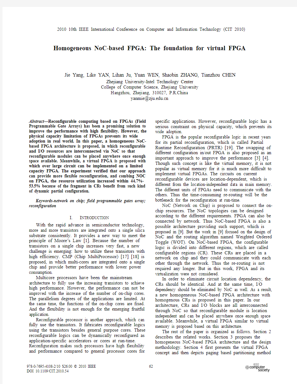
This section presents the proposed homogeneous NoC-based FPGA providing architecture support for virtual FPGA. The diagram of our architecture is shown in Fig. 1, which consists of three components: (1) Configurable Regions (CR) as reconfigurable logic, (2) I/O blocks as external I/O resources and (3) Network-on-chip (NoC) as internal interconnection structure.
Figure 1. Schematic of NoC-based FPGA architecture.
Configurable Regions (CR) are the reconfigurable logics resembling current dynamical reconfigurable FPGA [11], which consists of a number of Look Up Tables (LUT), flip-flops and internal interconnect structure. It’s designed for module based system design methodology and a homogeneous CRs array is proposed in which CRs are all the same. The granularity of CR is large enough to accommodate most single modules. And the modules placed on CRs make up of the full system further. It’s also called hierarchical design methodology. Besides, the internal interconnection structure is similar to traditional FPGA too. While there are short wires and longer wires through out full CRs, but no wires through out full chip for simplicity.
I/O blocks are the I/O resources connected to external I/O pins directly. Through these blocks, on-chip system could be loosely coupled with off-chip computing systems or tightly coupled with on-chip resources with fixed functions.
Network-on-chip (NoC) is the interconnection fabric connecting CRs, and I/O blocks. In this architecture, CLICHé is chose as the NOC topology. Detailed communication implemented by NOC using CLICHé can be found in [10]. CR and I/O block are attached to a router on NoC via a Network Interface (NI). NoC in proposed architecture is an adaptively routing network, on which the routing path is decided on a per hop basis involving dynamic arbitration mechanisms. So the routing path is not determined when a module is placed on any CR, and the
communications between CRs and CR with I/O block can be dynamically determined. It results in more complex node implementations but offers benefits like dynamic load balancing [12]. But we do not detail the design of NoC in the paper. The work on NoC can be found in [20] [21].
IV.FPGA V IRTUALIZATION
In this section, the concept of virtual FPGA will be described firstly. Then, how to implement virtualization on the proposed NoC-based architecture is presented, which is paged virtual FPGA. At last operating supports for virtual FPGA are presented.
In virtual FPGA, the basic idea is borrowed from the similar ideas adopted in operating system to support the virtual memory, namely, dynamic loading, overlaying, partitioning, segmentation and pagination. PRTR can be used to implement dynamic loading; parts of circuit configuration can be loaded and configured on selected CRs at run-time when the other CRs are executing normally without being interrupted. Overlaying is also easy to be implemented by using PRTR. The difference is that when a recently least used part of the circuits is swapped out, the states of the circuits should be stored instead of the configuration. Because the configuration will not be changed but the states of the circuits will at run-time. When swapping in a part of the circuits which was previously swapped out, the states of the circuits must be reloaded in addition to the configuration.
Partitioning is one of the basic ideas of virtual FPGA. It divides circuit and configurable logic into basic units that can be swapped in and out as the smallest size. Generally speaking, there are two kinds of partitioning methods: paging and segmentation. Paging is a method which divides configurable logic into blocks of fixed size, and segmentation divides configurable logic into blocks of variable sizes. Paging will cause internal fragments within pages while segmentation causes external fragments between segments. In this paper, paging based virtual FPGA is presented. In addition, sharing of the input and output resources is another problem should be considered.
Given the FPGA architecture proposed in Section 2, paging is easy to implement on the organization. On this architecture, reconfigurable logic is designed as an array of identical fixed size regions, called CR. Intuitively a CR is a natural page. As shown in Fig. 2 (a), each CR is assigned with a page number.
Operating system is also required to be modified to support virtual FPGA, including run-time reconfiguration management and virtual FPGA page table management. A run-time reconfiguration management module should be added. It will be responsible for loading configurations to CRs and making the decision of swapping configurations in to and out of CRs. And a virtual FPGA page table is maintained by operating system to record the utilization of CRs. An example of the structure of virtual FPGA page table is shown in Fig. 3. The table has the same number of entries as the number of actual CRs. As shown in Fig. 3, each entry of the table has six items: a Validation Bit (V.), a Busy Bit (Busy), Page Number (Page No.), Task ID, Module ID and Time Stamp in Fig. respectively. Validation Bit indicates whether the corresponding CR is used. Busy Bit indicates whether the corresponding function on CR is executing. Page Number is the number of the corresponding CR. Task ID and Module ID indicate which task and which module the CR is occupied by respectively. And at last, Time Stamp records the time it is called last time.
Figure 2. Paging based partitioning.
Page No.Task ID Module ID
1
Figure 3. Structure of virtual FPGA page table.
Once receiving a request for a hardware function from an application, operating system checks whether the corresponding module is already configured on the physical CR. When the module does exist and is not busy, it starts to execute. If the module does not exist or it is busy, a fault occurs. In such cases, the application is handed up when the module is busy, or operating system loads the requested module again. When dynamically loading a module is requested, operating system checks whether there are enough free CRs available. If no free CRs are available, one or more lest recently used modules are selected and swapped out by using LRU algorithm. Fig. 2 (b) shows an example, in which P5 is assumed as lest recently used one. In this example, when free CRs are requested, P6, P7, P8, P9 are allocated first. Then when more CR is requested, P5 is freed by swapped out and reconfigured.
V.E XPERIMENTS AND R ESULTS
An emulation prototype system is constructed to verify the proposed architecture. The system is composed of a personal computer, equipped with two Xilinx ML555 development boards via PCI-E. Each ML555 board equipped with a XC5VLX50T FPGA including 7,200 slices, and each slice contains four LUTs and four flip-flops [16]. Each FPGA is viewed as a CR cluster in the proposed architecture, and a software simulation of NoC is implemented running on PC to connect two FPGAs. The granularity of CR is
important and difficult to determine. Although, there is 7,200 slices on each FPGA in our platform, we take 60 Virtex 5 (V5) slices as a CR in our experiments.
Given the prototype system organization, the following phases should be added or modified compared to traditional module based design flow of traditional FPGA: (1) module size adjustment and (2) implementation of each module into a single CR. In module size adjustment phase, large modules are divided into smaller ones which can fit into a single CR, and small modules are merged to a larger one which can occupy an entire CR to improve the resource utilization rate. In implementation phase, modules can be mapped to any CRs according to homogeneous CR array. And each module is assigned a unique identifier used like a network address. Routing phase is not needed because the communication is adaptively routed at run-time.
Figure 4. Implementation of 3-DES on virtual FPGA.
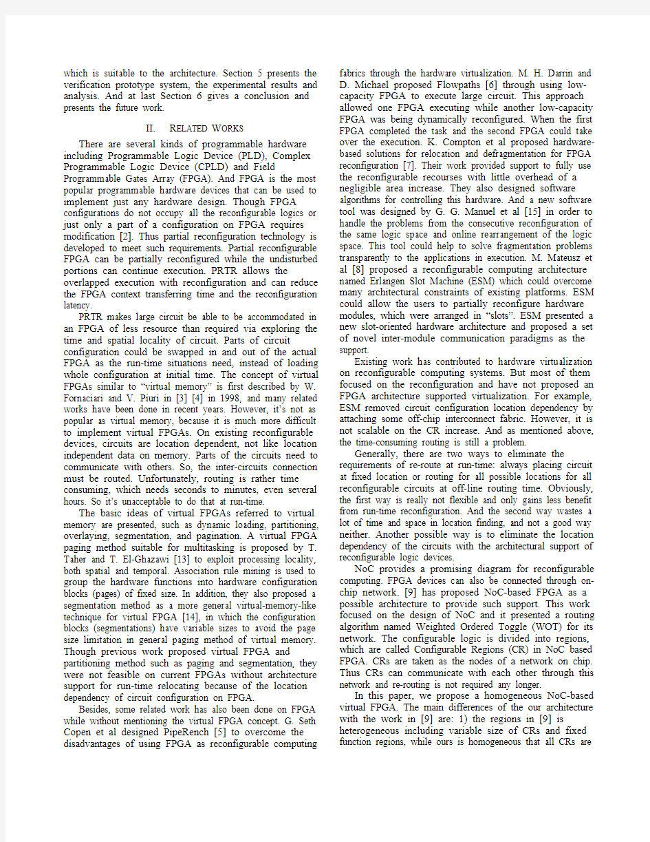
Figure 5. LUTs utilization in each module. The 3-DES crypto algorithm can be implemented on triple DES function modules or by time multiplexing single DES function modules. As shown in Fig. 4, the 3-DES crypto algorithm can not accommodate in two CRs of this granularity. Fortunately, it can be implemented with 4 modules of this granularity on virtual FPGA. M0 contains DES Top module and SBox module, M1 contains Keyschedule-1 module, M2 contains Keyschedule-2 module and M3 contains Blocktop module. The four modules are limited in two CRs when executing. The LUTs based resources utilization of each module is shown in Fig. 5, which is 62.9% in M0, 62.1% in M1 same to M2 and 33.3% in M3. The resources utilization on 3 different platforms is
shown in Table 1. DES implemented on NoC-based FPGA
takes 4 CRs with 240 Slices totally and uses 190 slices and
529 LUTS. DES on Virtex 5 FPGA takes 186 slices in total and used 465 LUTs. And 3-DES on Virtex 5 FPGA takes 750 slices in total and used 1700 LUTs.
The utilization comparison on LUT basis of three implementations is shown in Fig. 6. The result shows that DES implemented on the proposed homogeneous NoC-based FPGA takes 190 slices totally and the utilization rate on LUTs basis is 55.1%, allowing for the benefit of dynamic configuration, the utilization of LUT is 110.2%, and that on Virtex 5 is 62.5%. The LUTs utilization rate of 3-DES on Virtex 5 is 56.7%. Comparing the three results, the utilization of LUT of DES on NOC-based FPGA increases by 47.7% referring to DES on v5, and 53.5% referring to 3-DES on v5.
TABLE I.
3-DES IMPLEMENTATION ON 3 DIFFERENT P LATFORMS
Item
Used Slices
Used LUTs
Used CRs(actual)
DES on NoC-based
FPGA 190 529 4(2)
DES on v5 186 465 N/A 3-DES on v5
750
1,700
N/A
based FPGA
utilization rate on LUTs
Figure 6. The utilization comparision on LUT basis.
The experiment verifies the NoC-based architecture and the design methodology. And the results show that a system implemented according to virtual FPGA with modules equal
to or smaller than the size of CR takes more reconfigurable
resources than on a single configurable region of large
enough capacity, which is 29% refers to DES because of the division of modules. As Fig. 5 suggests, the utilization of each CR can be enhanced by choosing a better granularity of CR, which, in our experiment, the average utilization of CR is only 55.1%. Further improvement should be taken out to develop a better way to determine the granularity for applications. Less internal fragment will make a better performance. Considering the common configuration speed in FPGA, improving it will result in a better performance. Also, the communication cost between modules via NoC should be evaluated and optimized further. VI. C ONCLUSION AND F UTURE W ORK To fully use the increasing transistors on one die, a new
homogeneous NoC-based FPGA architecture is proposed in
this paper. In this architecture, reconfigurable resource and
I/O resource are all interconnected via NoC so that reconfigurable modules are location independent and can be placed anywhere in the network once enough space available. Meanwhile, virtual FPGA is proposed based on the FPGA architecture in a way similar to virtual memory used in operating system. With the virtual FPGA, any circuit can be implemented on a limited capacity FPGA by run-time reconfiguration and swapping in/out modules to explore their time and spatial locality.
A prototype system is constructed to verify the architecture and the virtual FPGA based on our architecture. The experiment verifies that the NoC-based architecture and the design methodology are feasible. And the results show that a system requiring more physical capacity can be implemented with virtual FPGA.
There is lots of work to do in the future. Further improvement should be taken out to reduce the configuration speed, especially the configuration transferring speed. And the communication cost between modules via NoC should be evaluated and optimized in the future. Besides, the architecture should be enhanced to support better partitioning method like segmentation and increase the reconfigurable logic utilization.
A CKNOWLEDGMENT
This work was supported by Supported by the State Key Laboratory of High-end Server & Storage Technology(No. 2009HSSA10) and Research Foundation of Education Bureau of Zhejiang Province under Grant No. Y200909683.
R EFERENCES
[1]G. Moore, “Cramming more components onto integrated circuits”,
Electron. Mag., vol. 38, No. 8, Apr. 1965.
[2]K. Compton and S. Hauck, “Reconfigurable computing: a survey of
systems and software”, ACM Computing Surveys, vol. 34, pp. 171-
210, Jun. 2002, doi: 10.1145/508352.508353.
[3]W. Fornaciari and V. Piuri, “Virtual FPGAs: Some Steps Behind the
Physical Barriers”, Proc. Parallel and Distributed Processing (IPPS/SPDP 98), LNCS, vol 1388, 1998, pp. 7-12, doi: 10.1007/3-
540-64359-1_665.
[4]W. Fornaciari and V. Piuri, “General methodologies to virtualize
FPGAs in Hw/Sw systems”, Proc. 1998 Midwest Symposium on Circuits and Systems, 1998, pp. 90-93.
[5]G. Seth Copen, S. Herman, B. Mihai, C. Srihari, M. Matt, and R. R.
Taylor, “PipeRench: A Reconfigurable Architecture and Compiler”, Computer, vol. 33, no. 4, Apr. 2000, pp. 70-77, doi:
10.1109/2.839324.
[6]M. H. Darrin and D. Michael, “Executing large algorithms on low-
capacity FPGAs using flowpath partitioning and run-time reconfiguration”, Microprocessors and Microsystems, vol. 31, no. 5, pp. 302-312, Nov. 2007, doi: 10.1016/j.micpro.2006.10.001. [7]K. Compton, L. Zhiyuan, J. Cooley, S. Knol and S. Hauck,
“Configuration relocation and defragmentation for run-time reconfigurable computing”, IEEE Transactions on Very Large Scale
Integration (VLSI), vol. 10, no. 3, pp. 209-220, Jun. 2002, doi:
10.1109/TVLSI.2002.1043324.
[8]M. Mateusz, J, T. rgen, A. Ali, and B. Christophe, “The Erlangen Slot
Machine: A Dynamically Reconfigurable FPGA-based Computer”,
Journal of VLSI Signal Processing, vol. 47, no. 1, Kluwer Academic
Publishers, Apr. 2007, pp. 15-31, doi: 10.1007/s11265-006-0017-6. [9]R. Gindin, I. Cidon, and I. Keidar, “NoC-Based FPGA: Architecture
and Routing”, Proc. the First international Symposium on Networks-
on-Chip (NOCS 07), May. 2007, pp. 253-264, doi:
10.1109/NOCS.2007.31.
[10]Shashi Kumar1, Axel Jantsch, Juha-Pekka Soininen, Martti Forsell,
Mikael Millberg, Johny ?erg, Kari Tiensyrj?, and Ahmed Hemani3,
“A network on chip architecture and design methodology”, Proceedings of the IEEE Computer Society Annual Symposium on
VLSI (ISVLSI.02), 25 Apr 2002-26 Apr 2002, pp. 105 – 112, doi:
10.1109/ISVLSI.2002.1016885.
[11]S. Brown and J. Rose, “FPGA and CPLD architectures: a tutorial”,
Design & Test of Computers, IEEE, vol. 13, pp. 42-57, 1996.
[12] B. Tobias and M. Shankar, “A survey of research and practices of
Network-on-chip”, ACM Computing Surveys, vol. 38, no. 1, Jun.
2006, doi: 10.1145/1132952.1132953.
[13]T. Taher and T. El-Ghazawi, “Exploiting processing locality through
paging configurations in multitasked reconfigurable systems”, Proc.
20th International Conference on IEEE Parallel and Distributed Processing Symposium (IPDPS 06), Jun. 2006, doi:
10.1109/IPDPS.2006.1639459.
[14]M. Taher, M. Taher, and T. El-Ghazawi, “A Segmentation Model for
Partial Run-Time Reconfiguration”, Proc. International Conference
on Field Programmable Logic and Applications (FPL 06), 2006, pp.
1-4, doi: 10.1109/FPL.2006.311305.
[15]G. G. Manuel, R. A. Gustavo, L. S. Miguel, and M. F. Jose, “Run-
Time Management of Logic Resources on Reconfigurable Systems”,
Proc. the conference on Design, Automation and Test in Europe
(DATE 03), vol. 1, Dec. 2003, pp. 974-979.
[16]Xilinx Inc., “Virtex-5 Family Overview LX, LXT, and SXT
Platforms”, 2007.
[17]N. Eisley, L. Peh and L. Shang, “Leveraging on-chip networks for
data cache migration in chip multiprocessors”, Proc. the 17th international Conference on Parallel Architectures and Compilation
Techniques (PACT 08), Oct. 2008, pp. 197-207, doi:
10.1145/1454115.1454144.
[18]M. Kandemir, F. Li, M.J. Irwin and S.W. Son, “A novel migration-
based NUCA design for chip multiprocessors”, Proc. the 2008 ACM/IEEE Conference on Supercomputing (SC 08), Nov. 2008,
IEEE Press, pp. 1-12.
[19]K. Compton and S. Hauck, “Reconfigurable Computing: A Survey of
Systems and Software”, ACM Computing Surveys, vol. 34, no. 2, pp.
171-210. June 2002.
[20] D. Kim, K. Kim, J. Kim, S. Lee and H. Yoo, “Solutions for Real Chip
Implementation Issues of NoC and Their Application to Memory-
Centric NoC”, Proc. the First international Symposium on Networks-
on-Chip (NOCS 07), May 2007, pp. 30-39.
[21]R. Gindin, I. Cidon and I. Keidar, “NoC-Based FPGA: Architecture
and Routing”, Proc. the First international Symposium on Networks-
on-Chip (NOCS 07), May 2007, pp. 253-264.
基于FPGA的嵌入式技术 “嵌入式系统是一个面向应用、技术密集、资金密集、高度分散、不可垄断的产业,应用在通信、航空航天、消费类电子产品等各种领域中。”随着经济的发展,各领域对嵌入式产品的应用需求呈现多样化,嵌入式系统设计技术和芯片技术也不断革新。传统设计ASIC的成本很低,但设计周期长、上市时间晚、风险较大。基于FPGA的嵌入式系统设计可以缩短设计周期,加快上市时间,抢占市场先机。 1、概述 现场可编程门阵列FPGA(Field-Programmable Gate Array)是由复杂可编程逻辑器件CPLD(Complex-Programmable Logical Device)发展而来。其功能强大,设计灵活。设计性能能够与ASIC媲美。而且,性能价格比也可以与ASIC抗衡。因此,FPGA在嵌入式系统设计领域越来越重要。 FPGA的基本结构由以下几个部分:CLB(Configurable Logic Blocks)、IOB (Input/Output Blocks)和PI(Programmable Interconnection)。随着工艺的进步和应用需求,一般在FPGA中还包含以下可选结构:Memory、数字时钟管理单元、Select I/O、乘法器和加法器、硬IP核和微处理器等。随着FPGA性能提高和设计人员能力提高,FPGA将进一步扩大可编程芯片领地,使专用芯片更高端和超复杂。[1] 2、可编程片上系统(SOPC) 可编程片上系统(SOPC)是一种特殊的嵌入式系统。片上是指由单个芯片完成整个系统的主要逻辑功能;可编程使其具有灵活的设计方式,可以裁剪、扩充、升级。并且,SOPC结合了SOC和FPGA各自的优点,具备软硬件在系统可编程的功能。 SOPC至少包含一个嵌入式处理器内核,具有小容量片内高速RAM,一部分IP Core(简称IP),大量的片上可编程逻辑,处理器调试接口和FPGA编程接口等。SOPC设计技术涵盖了嵌入式系统设计技术的全部内容。包含以处理器和实时多任务操作系统为中心的软件设计技术、以PCB和信号完整性分析为基础的电路设计技术及软硬件协同设计技术。[2] 3、IP资源复用理念与IP Core设计 IP资源复用是指在集成电路设计中,通过继承、共享或购买所需的知识产权内核,利用EDA工具进行设计、综合和验证,加速流片设计过程,降低开发风险。IP核复用技术已逐渐成为现代ASIC设计的重要手段,不仅应用于专用集成电路设计,也广泛使用于基于FPGA的嵌入式系统设计领域。设计师倾向于使用IP内核保持和提高产量。
3.键盘的应用,第一排。 #include
case 0x7e:num=4; break; } } while(temp!=0xf0) { temp=P3; temp=temp&0xf0; } } dula=1; P0=table[num-1]; dula=0; } } void delay(uint z) //延时函数 { uint x,y; for(x=z;x>0;x--) for(y=110;y>0;y--); }
基于FPGA的软核处理器在嵌入式中的运用 随着一些ASIC 应用开发日益受到成本的困扰,OEM日渐转向FPGA 来构建自己的系统。这些系统中绝大多数需要一个处理器为了给设计者提供一个为FPGA 优化的灵活的嵌入式处理器方案,满足16位和32位嵌入式处理器市场的需求,Altera公司公司推出Nios II 系列32位RSIC嵌入式处理器。这是Altera的第二代软核嵌入式处理器,性能超过200DMIPS,在Altera FPGA 中实现仅需35美分。因为Nios II处理器是软核,因此开发者能够从无限的系统配置组合中选择满足性能和成本目标的方案,而不必为系统级设计考虑采用ASIC。 与此同时赛灵思公司(Xilinx,Inc.)宣布推出Virtex?-5 FXT 器件。这些FPGA 器件在业界率先集成了嵌入式PowerPC?440处理器模块、高速RocketIO?GTX收发器和专用XtremeDSP?处理能力。作为65nm Virtex-5系列的第四款平台, Virtex-5 FXT提供了极高的性能,还可帮助设计人员降低系统成本、缩小板尺寸并减少元件数量。在赛灵思公司以及业界领导厂商提供的逻辑、嵌入式和DSP开发工具以及IP内核的支持下,Virtex-5 FXT FPGA为有线和无线通信、音频/视频广播设备、军事、航空航天、工业系统以及其它众多应用提供了一个终极系统集成平台。 从FPGA两大主要生产公司的设计方向上我们可以看出,未来的嵌入式发展将向基于软核处理器的FPGA发展,也就是常称之为的SoPC(可编程片上系统Sysein on a Programmable Chip)设计思想。基于FPGA 的SoPC 具有设计灵活、可裁减、可配置、可扩充、可升级的特点,并具备软硬件在系统可编程的功能。我们借助强大得EDA 工具,在设计嵌入式系统时,不仅可以实现软件的可裁减性,同样可以实现硬件的可裁减性,并且可以自主定义处理器的引脚,方便PCB板布线,同样方便更改设计。 Altera 的Nios 处理器和Stratix FPGA 是其Maestro 平台的核心,它具有的核心功能提供了前所未有数据为中心的功能。能够用于任何需要32位嵌入式处理器的应用。据介绍,Nios II 系列包括三种软CPU 核,一个是最大系统性能,一个是为最少逻辑使用量优化的,还有一个是二者之间的平衡。所有核都是100% 代码兼容,让设计者根据系统需求变化改变C P U ,而不会影响现有的软件投入。Nios II系列是建立在前一代成功的基础之上,以部分的资源提供高得多的性能。 另外,Nios II处理器具有健全的软件开发套件,包括编译器、集成开发环境(IDE ),JTAG 调试器,实时操作系统(RTOS)和TCP/IP 协议栈。Nios II嵌入式处理器结合Altera的低成本Cyclone 系列和高性能StratixII 系列FPGA 和HardCopy 结构化ASIC系列,在价格、性能和功能上具有很高的灵活性。Lytle先生认为,Nios II系列增加了Altera 在嵌入式处理器市场上的机会。当第一代Nios 处理器为Altera 开辟了新的应用和市场之门时,Nios II嵌入式处理器系列有望增加公司在16位和32位嵌入式处理器市场上的机会。从使用Altera 低成本Cyclone FPGA 系列的探鱼器和引擎测试仪到使用高性能Stratix系列的视频处理和高级通信系统,Altera的软核嵌入式处理器已经成为新应用中使用可编程逻辑的推动力。 在单片器件上集成重要处理性能和SERDES元件,可为那些需要节约板级空间和成本、同时又需要满足高性能要求的设计人员提供巨大的价值。例如,在无线应用中,Virtex-5
9.3.1 矩阵键盘的工作原理和扫描确认方式 来源:《AVR单片机嵌入式系统原理与应用实践》M16华东师范大学电子系马潮 当键盘中按键数量较多时,为了减少对I/O 口的占用,通常将按键排列成矩阵形式,也称为行列键盘,这是一种常见的连接方式。矩阵式键盘接口见图9-7 所示,它由行线和列线组成,按键位于行、列的交叉点上。当键被按下时,其交点的行线和列线接通,相应的行线或列线上的电平发生变化,MCU 通过检测行或列线上的电平变化可以确定哪个按键被按下。 图9-7 为一个 4 x 3 的行列结构,可以构成12 个键的键盘。如果使用 4 x 4 的行列结构,就能组成一个16 键的键盘。很明显,在按键数量多的场合,矩阵键盘与独立式按键键盘相比可以节省很多的I/O 口线。 矩阵键盘不仅在连接上比单独式按键复杂,它的按键识别方法也比单独式按键复杂。在矩阵键盘的软件接口程序中,常使用的按键识别方法有行扫描法和线反转法。这两种方法的基本思路是采用循环查循的方法,反复查询按键的状态,因此会大量占用MCU 的时间,所以较好的方式也是采用状态机的方法来设计,尽量减少键盘查询过程对MCU 的占用时间。 下面以图9-7 为例,介绍采用行扫描法对矩阵键盘进行判别的思路。图9-7 中,PD0、PD1、PD2 为3 根列线,作为键盘的输入口(工作于输入方式)。PD3、PD4、PD5、PD6 为4根行线,工作于输出方式,由MCU(扫描)控制其输出的电平值。行扫描法也称为逐行扫描查询法,其按键识别的过程如下。 √将全部行线PD3-PD6 置低电平输出,然后读PD0-PD2 三根输入列线中有无低电平出现。只要有低电平出现,则说明有键按下(实际编程时,还要考虑按键的消抖)。如读到的都是高电平,则表示无键按下。 √在确认有键按下后,需要进入确定具体哪一个键闭合的过程。其思路是:依
#include
长沙学院 《单片机原理及应用》 课程设计说明书 题目液晶显示4*4矩阵键盘按键号 程序设计 系(部) 电子与通信工程系 专业(班级) 电气1班 姓名龙程 学号2011024109 指导教师刘辉、谢明华、王新辉、马凌 云 起止日期2014.5.19—2014.5.30
长沙学院课程设计鉴定表
《单片机技术及应用》课程设计任务书系(部):电子与电气工程系专业:11级电子一班指导教师:谢明华、刘辉
目录 前言 (5) 一、课程设计目的 (6) 二、设计内容及原理 (6) 2.1 单片机控制系统原理 (6) 2.2阵键盘识别显示系统概述 (6) 2.3键盘电路 (7) 2.4 12864显示器 (8) 2.5整体电路图 (9) 2.6仿真结果 (9) 三、实验心得与体会 (10) 四、实验程序 (10) 参考文献 (18)
前言 单片机,全称单片微型计算机(英语:Single-Chip Microcomputer),又称微控制器 应(不用外接硬件)和节约成本。它的最大优点是体积小,可放在仪表内部,但存储量小,输入输出接口简单,功能较低。由于其发展非常迅速,旧的单片机的定义已不能满足,所以在很多应用场合被称为范围更广的微控制器;从上世纪80年代,由当时的4位、8位单片机,发展到现在的32位300M的高速单片机。现代人类生活中所用的几乎每件有电子器件的产品中都会集成有单片机。手机、电话、计算器、家用电器、电子玩具、掌上电脑以及鼠标等电子产品中都含有单片机。汽车上一般配备40多片单片机,复杂的工业控制系统上甚至可能有数百片单片机在同时工作!单片机的数量不仅远超过PC机和其他计算机的总和,甚至比人类的数量还要多。 是以电流刺激液晶分子产生点、线、面配合背部灯管构成画面。由一定数量的彩色或黑白像素组成,放置于光源或者反射面前方。液晶显示器功耗低,因此倍受工程师青睐,适用于使用电池的电子设备。英国科学家在上世纪制造了第一块液晶显示器即LCD。而第一台可操作的LCD基于动态散射模式(Dynamic Scattering Mode,DSM),是RCA公司乔治·海尔曼带领的小组开发的。 LED点阵屏通过LED(发光二极管)组成,以灯珠亮灭来显示文字、图片、动画、视频等,是各部分组件都模块化的显示器件,通常由显示模块、控制系统及电源系统组成。LED点阵显示屏制作简单,安装方便,被广泛应用于各种公共场合,如汽车报站器、广告屏以及公告牌等。 交叉处不直接连通,而是通过一个按键加以连接。这样,一个端口(如P1口)就可以构成4*4=16个按键, 键盘是合理的。
1 4×4矩阵式键盘识别显示系统概述 矩阵式键盘模式以N个端口连接控制N*N个按键,实时在LED数码管上显示按键信息。显示按键信息,既降低了成本,又提高了精确度,省下了很多的I/O 端口为他用,相反,独立式按键虽编程简单,但占用I/O口资源较多,不适合在按键较多的场合应用。并且在实际应用中经常要用到输入数字、字母、符号等操作功能,如电子密码锁、电话机键盘、计算器按键等,至少都需要12到16个按键,在这种情况下如果用独立式按键的话,显然太浪费I/O端口资源,为了解决这一问题,我们使用矩阵式键盘。 矩阵式键盘又称行列键盘,它是用N条I/O线作为行线,N条I/O线作为列线组成的键盘。在行线和列线的每个交叉点上设置一个按键。这样键盘上按键的个数就为N×N个。这种行列式键盘结构能有效地提高单片机系统中I/O口的利用率。 最常见的键盘布局如图1.1所示。一般由16个按键组成,在单片机中正好可以用一个P口实现16个按键功能,这也是在单片机系统中最常用的形式,本设计就采用这个键盘模式。 图1.1 键盘布局
2系统主要硬件电路设计 2.1单片机控制系统原理 图2.1 单片机控制系统原理框图 2.2单片机主机系统电路 AT89C52单片机是51系列单片机的一个成员,是52单片机的简化版。内部自带2K字节可编程FLASH存储器的低电压、高性能COMS八位微处理器,与Intel MCS-52系列单片机的指令和输出管脚相兼容。由于将多功能八位CPU和闪速存储器结合在单个芯片中,因此,AT89C52构成的单片机系统是具有结构最简单、造价最低廉、效率最高的微控制系统,省去了外部的RAM、ROM和接口器件,减少了硬件开销,节省了成本,提高了系统的性价比。 图2.2 单片机主机系统图
目录 1 NiosⅡ CPU的体系结构3 NiosⅡ处理器的结构 (3) NiosⅡ处理器的基本组成 (3) Debug模块 (3) NiosⅡ开发环境简介 (3) 2 IP核4 SDRAM控制器 (4) 3 基于SOPC的温湿度监测系统设计5 系统总体设计方案 (5) SOPC硬件系统设计 (6) SOPC软件系统设计 (9) NiosⅡ软件系统设计 (9) NiosⅡ IDE C/C++Build属性配置 (13) 软件系统的设计流程 (15) 4 实验结果与分析15结论18
SOPC是可编程片上系统,即一种特殊的嵌入式系统。首先它是片上系统(SOC),由单个芯片完成整个系统的主要逻辑功能;其次,它是可编程系统,具有灵活的设计方式,可裁减、可扩充、可升级,并具备软硬件在系统可编程的功能。SOPC是基于FPGA解决方案的SOC,与ASIC的SOC解决方案相比,SOPC系统及其开发技术具有更多的特色。构成SOPC的途径有基于FPGA嵌入IP硬核的系统、基于FPGA嵌入IP软核的系统和基于HardCopy 技术的SOPC系统三种方式。本文介绍基于FPGA的嵌入IP软核的SOPC系统实现方法,设计了一种基于SOPC的温湿度监测系统。通过Quartus II 软件里的SOPC builder把Nios II Processor、Avalon总线、UART、SDRAM_controller、Flash Memory、Avalon三态桥等多个IP核集成生成系统所需的SOPC。传感器扩展板采用Mega8作为主控芯片,用于数据的采集、显示以及和PC的通信。同时配有由SPI总线控制的数码管,可以显示传感器的测量结果,以及与PC通信过程中的具体情况。对外采用波特率为115200的串口进行通信,用户可通过串口向该模块发出各种查询命令以查询传感器的状态。本次设计使用NiosII IDE编写应用程序,发送相应指令,获取温度和湿度的值,同时显示在Console窗口。 关键词: SOPC技术;FPGA开发板;IP核;温湿度监测;NiosⅡ处理器;Mega8芯片
矩阵控制键盘操作说明 键盘概述 控制器是智能电视监控系统中的控制键盘,也是个监控系统中人机对话的主要设备。可作为主控键盘,也可作为分控键盘使用。对整个监控系统中的每个单机进行控制。 键盘功能 1.中文/英文液晶屏显示 2.比例操纵杆(二维、三维可选)可全方位控制云台,三维比例操纵杆可控制摄像机的变倍 3.摄像机可控制光圈开光、聚集远近、变倍大小 4.室外云台的防护罩可除尘和除霜 5.控制矩阵的切换、序切、群组切换、菜单操作等 6.控制高速球的各种功能,如预置点参数、巡视组、看守卫设置、菜单操作等 7.对报警设备进行布/撤防及报警联动控制 8.控制各种协议的云台、解码器、辅助开头设置、自动扫描、 自动面扫及角度设定 9.在菜单中设置各项功能 10.键盘锁定可避免各种误操作,安全性高 11.内置蜂鸣器桌面上直接听到声音,可判断操作是否有效 技术参数 1.控制模式主控、分控 2.可接入分控数16个 3.可接入报警模块数239个 4.最大报警器地址1024个 5.最大可控制摄像机数量1024个 6.最大可控制监视器数量 64个 7.最大可控制解码器数量 1024个 8.电源 AC/DC9V(最低500mA的电源) 9.功率 5W 10.通讯协议Matri、PEL-D、PEL-P、VinPD 11.通讯波特率1200 Bit/S,2400 Bit/S,4800 Bit/S ,9600Bit/S, Start bit1,Data bit8,Stop bit1
接线盒的脚定义 控制线连接图 键盘按键说明 lris Focus Far 聚焦远 Focus Near 聚焦近 Zoom Tele 变倍大 Zoom Wide 变倍小 DVR 设备操作 DVR 功能键 Shift 用户登入 Login 退出键 Exit 报警记录查询 List 进入键盘主菜单 MENU 启动功能 F1/ON 关闭功能 F2/OFF 液晶显示区
《基于fpga的嵌入式系统设计》复习题 1、名词概念解释: (1)ASIC,FPGA,SOC,SOPC,NIOS II,I/O ,IP ; (2)VHDL,verilog HDL,HDL,EDA ; (3)功能仿真,后仿真,设计综合,设计验证; (4)嵌入式系统的定义: 以应用为中心、以计算机技术为基础、软硬件可裁剪、适应应用系统对功能、 可靠性、成本、体积、功耗等严格要求的专用计算机系统。 (5)嵌入式系统的组成: 嵌入式系统主要由嵌入式处理器、外围设备、嵌入式操作系统及应用软件等组 成,它是集软硬件于一体的可独立工作的“器件”。其中:嵌入式处理器是嵌入 式系统的核心部件,具有小型化、高效率、高可靠性、高集成度等特点。外围 设备是嵌入式系统中用于完成存储、通信、调试、显示等辅助功能的部件。 2、填空题 (1)NiosII处理器有三种运行模式:___________ ,___________ ,_____________ 。(2)CycloneII FPGA支持串行配置器件的isp编程,该特性是通过_____________利用JTAG接口实现的。 (3)在SOPC Builder中,复位地址的偏移量是________,异常地址的偏移量是________。(4)在NiosII的多处理器系统中,最常用的共享资源是____________。 (5)根据Flash是否支持处理器的直接读操作,NiosII处理的bootloader分成两种模式:________________bootloader、________________ bootloader。 (6)用uC/OS-II操作系统实现以太网与轻量IP功能的时候,以太网的中断号至少是____________。 (7)Altera公司的FPGA常用的配置方式: JTAG方式、___________、___________。(8)CycloneII FPGA上面集成的Block RAM为M4K,一个M4K的大小是________。(9)使用QuartusII进行FPGA设计的开发流程是:设计输入、__________、___________、仿真、_________ 。 (10)NiosII IDE为软件开发提供了4个主要功能:工程管理器、编辑器和编译器、调试器、____________ 。 (11)SOPC组件On-chip Memory可以用作RAM外,还可以设置成___________,甚至可以设置成双口存取。 (12)CycloneII EP2C35器件包含4个PLL,每个PLL均有_________个输出。其中第_________个输出的驱动能力最强。
矩阵键盘操作说明 一、系统复位 1按数字键0后,按MON键 2输入99后,按NEXT键 二、键盘视频选择 首先是监视器选择然后是摄像机选择 1、按键盘上的CLEAR键,清除键盘数字输入ENTER区中的数字显示 2、输入所选择的监视器号,该数字在键盘数字输入ENTER区中显示 3、按MON键,该监视器号在键盘监视器MONITOR区中显示 4、同时系统主机将返回该监视器对应的图像号,在键盘的摄像机CAMERA区中显示。 5、输入选择的摄像机号,该数字在键盘数字输入ENTER区中显示 6、按CAM键 7、系统主机将返回该图像号,在键盘的摄像机CAMERA区中显示则选择的图像再选择的 监视器上显示 三、图像区域切换 在指定的监视器上运行一个指定区域的图像切换,该功能可以在任何一个监视上浏览切换所有的图像操作步骤如下: 1、按键盘上CLERA键,清除数字输入ENTER区中的数字显示 2、输入所选择的监视器号,该数字在键盘数字输入ENTER区中显示 3、按MON键,该监视器号在键盘监视器MONITOR区中显示 4、输入区域切换中的开始图像号 5、按ON键,确认开始区域的开始图像 6、输入区域切换中的结束图像号 7按OFF键确定区域切换的结束图像 完成后则该监视器开始区域切换依次按照设定的图像号进行切换如要添加一个图像到切换序列中则: 1和设置区域切换的步骤一样重复1-3步,选择一个监视器,该监视必须已存在一个切换队列 2、输入所希望添加的摄像机图像好,该摄像机图像号必须在系统的最大允许摄像机图像号的范围内 3、按组合键ENTER-ON,ENTER键必须在前面,确定添加的图像。 如要在切换队列中删除一个图像: 1、和设置区域切换的步骤一样重复1-3步,选择一个监视器,该监视必须已存在一个切换队列 2输入所希望添加的摄像机图像好,该摄像机图像号必须在这个序列切换范围内。 3、按组合键ENTER-OFF,ENTER必须在前面,确认删除图像。 四、报警设置 单布防 针对需要布防的防区一个一个的布防,防区布防后,根据监视器与防区触点权限表,自动将该防区分配到与之对应的监视器上。一旦报警,则与之相关的报警监视器就可以对这个报警防区进行响应。具体操作如下1、输入防区号 2、按组合键ARM-ON,ARM键必须先按,对该报警防区进行确认。 全布防。撤防即按ARM-OFF键 1、输入数字键0
二、实验原始数据记录 1.实验现象 当设计文件加载到目标器件后,将数字信号源模块的时钟选择为1KHZ,按下矩阵键盘的某一个键,则在数码管上显示对应的这个键标识的键值,当再按下第二个键的时候前一个键的键值在数码管上左移一位。按下“*”键则在数码管是显示“E”键值。按下“#”键在数码管上显示“F”键值。 2.实验图片记录 湖南科技大学 物理与电子科学学院专业实验报告 实验课程:FPGA 实验原理 实验项目:矩阵键盘显示电路的设计专业:物理与电子科学学院班级:电子信息科学与技术3班姓名:马竞怡学 号: 1308020328 实验日期:年月日
实验报告 一、实验目的内容及步骤 1.实验目的 1)了解普通4×4键盘扫描的原理。2)进一步加深七段码管显示过程的理解。3)了解对输入/输出端口的定义方法。 2..4×4矩阵键盘电路原理图 信号名称 对应FPGA 管脚名 说明 KEY-C0AC18 钜阵键盘的第1列选择KEY-C1AC17钜阵键盘的第2列选择KEY-C2AD17钜阵键盘的第3列选择KEY-C3AC16钜阵键盘的第4列选择KEY-R0AD16钜阵键盘的第1行选择KEY-R1AC15钜阵键盘的第2行选择KEY-R2AD15钜阵键盘的第3行选择KEY-R3 AC14 钜阵键盘的第4行选择 3..实验步骤 1)打开QUARTUSII 软件,新建一个工程。 2)建完工程之后,再新建一个VHDL File,打开VHDL 编辑器对话框。 3)按照实验原理和自己的想法,在VHDL 编辑窗口编写VHDL 程序,用户可参照光 盘中提供的示例程序。 4)编写完VHDL 程序后,保存起来。方法同实验一。 5)对自己编写的VHDL 程序进行编译并仿真,对程序的错误进行修改。 6)编译仿真无误后,依照4X4矩阵键、数码管与FPGA 的管脚连接表(表或参照附 录进行管脚分配。表10-2是示例程序的管脚分配表。分配完成后,再进行全编译一次,以使管脚分配生效。 7)用下载电缆通过JTAG 口将对应的sof 文件加载到FPGA 中。观察实验结果是否 与自己的编程思想一致。 实验预习报告 一、实验原理及公式 通常在一个键盘中使用了一个瞬时接触开关,并且用如图10-1所示的简单电路,微处理器可以容易地检测到闭合。当开关打开时,通过处理器的I/O 口的一个上拉电阻提供逻辑1;当开关闭合时,处理器的/IO 口的输入将被拉低得到逻辑0。可遗憾的是,开关并不完善,因为当它们被按下或者被释放时,并不能够产生一个明确的1或者0。尽管触点可能看起来稳定而且很快地闭合,但与微处理器快速的运行速度相比,这种动作是比较慢的。当触点闭合时,其弹起就像一个球。弹起效果将产生如图10-2所示的好几个脉冲。弹起的持续时间通常将维持在5ms ~30ms 之间。如果需要多个键,则可以将每个开关连接到微处理器上它自己的输入端口。然而,当开关的数目增加时,这种方法将很快使用完所有的输入端口。 键盘扫描的实现过程如下:对于4×4键盘,通常连接为4行、4列,因此要识别按键,只需要知道是哪一行和哪一列即可,为了完成这一识别过程,我们的思想是,首先固定输出4行为高电平,然后输出4列为低电平,在读入输出的4行的值,通常高电平会被低电平拉低,如果读入的4行均为高电平,那么肯定没有按键按下,否则,如果读入的4行有一位为低电平,那么对应的该行肯定有一个按键按下,这样便可以获取到按键的行值。同理,获取列值也是如此,先输出4列为高电平,然后在输出4行为低电平,再读入列值,如果其中有哪一位为低电平,那么肯定对应的那一列有按键按下。 获取到行值和列值以后,组合成一个8位的数据,根据实现不同的编码在对每个按键进行匹配,找到键值后在7段码管显示。 (矩阵键盘) 成绩:教师:
1 NiosⅡ CPU的体系结构3 1.1 NiosⅡ处理器的结构 (3) 1.2 NiosⅡ处理器的基本组成 (3) 1.3 Debug模块 (3) 1.4 NiosⅡ开发环境简介 (3) 2 IP核4 2.1 SDRAM控制器 (4) 2.2FLASH (5) 3 基于SOPC的温湿度监测系统设计5 3.1 系统总体设计方案 (5) 3.2 SOPC硬件系统设计 (6) 3.3 SOPC软件系统设计 (9) 3.3.1 NiosⅡ软件系统设计 (9) 3.3.2 NiosⅡIDE C/C++Build属性配置 (13) 3.3.3 软件系统的设计流程 (15) 4 实验结果与分析15结论18
SOPC是可编程片上系统,即一种特殊的嵌入式系统。首先它是片上系统(SOC),由单个芯片完成整个系统的主要逻辑功能;其次,它是可编程系统,具有灵活的设计方式,可裁减、可扩充、可升级,并具备软硬件在系统可编程的功能。SOPC是基于FPGA解决方案的SOC,与ASIC的SOC解决方案相比,SOPC系统及其开发技术具有更多的特色。构成SOPC的途径有基于FPGA嵌入IP硬核的系统、基于FPGA嵌入IP软核的系统和基于HardCopy 技术的SOPC系统三种方式。本文介绍基于FPGA的嵌入IP软核的SOPC系统实现方法,设计了一种基于SOPC的温湿度监测系统。通过Quartus II 软件里的SOPC builder把Nios II Processor、Avalon总线、UART、SDRAM_controller、Flash Memory、Avalon三态桥等多个IP核集成生成系统所需的SOPC。传感器扩展板采用Mega8作为主控芯片,用于数据的采集、显示以及和PC的通信。同时配有由SPI总线控制的数码管,可以显示传感器的测量结果,以及与PC通信过程中的具体情况。对外采用波特率为115200的串口进行通信,用户可通过串口向该模块发出各种查询命令以查询传感器的状态。本次设计使用NiosII IDE编写应用程序,发送相应指令,获取温度和湿度的值,同时显示在Console窗口。 关键词: SOPC技术;FPGA开发板;IP核;温湿度监测;NiosⅡ处理器;Mega8芯片
矩阵键盘与数码管显示 摘要 矩阵式键盘乃是目前使用较为广泛的一种键盘模式,该系统以N个端口连接控制N*N个按键,即时在LED数码管上。单片机控制的据这是键盘显示系统,该系统可以对不同的按键进行实时显示,其核心是单片机和键盘矩阵电路部分,主要对按键与显示电路的关系、矩阵式技术及设备系统的硬件、软件等各个部分进行实现。4*4矩阵式键盘采用89C51单片机为核心,主要由矩阵式键盘电路、译码电路、显示电路等组成,软件选用C语言编程,单片机将检测到的按键信号转换成数字量,显示于数码管显示器,系统灵活性强,易于操作,可靠性能好。单片机简介及主系统电路 单片机是一种集成电路芯片,是采用超大规模集成电路技术把具有数据处理能力的中央处理器CPU随机存储器RAM、只读存储器ROM、多种I/O口和中断系统、定时器/计时器等功能(可能还包括显示驱动电路、脉宽调制电路、模拟多路转换器、A/D转换444器等电路)集成到一块硅片上构成的一个小而完善的微型计算机系统,在工业控制领域的广泛应用。从上世纪80年代,由当时的4位、8位单片机,发展到现在的32位300M的高速单片机。单片机在工业控制领域广泛应用,它由芯片内仅有CPU的专用处理器发展而来。最早的设计理念是通过将大量外围设备和CPU集成在一个芯片中,使计算机系统更小,更容易集成进复杂的而对体积要求严格的控制设备当中,本次课程设计我们采用的是AT89C51型号的单片机。 AT89C51单片机是51系列单片机的一个成员,是8051单片机的简化版。内部自带2K字节可编程FLASH存储器的低电压、高性能COMS八位微处理器,与Intel MCS-51系列单片机的指令和输出管脚相兼容。由于将多功能八位CPU和闪速存储器结合在单个芯片中,因此,AT89C2051构成的单片机系统是具有结构最简单、造价最低廉、效率最高的微控制系统,省去了外部的RAM、ROM和接口器件,减少了硬件开销,提高了系统的性价比。其最小系统电路图如下:
基于FPGA的嵌入式Linux软硬件设计 摘要:实现了一种全集成可变带宽中频宽带低通滤波器,讨论分析了跨导放大器-电容(OTA—C)连续时间型滤波器的结构、设计和具体实现,使用外部可编程电路对所设计滤波器带宽进行控制,并利用ADS软件进行电路设计和仿真验证。仿真结果表明,该滤波器带宽的可调范围为1~26 MHz,阻带抑制率大于35 dB,带内波纹小于0.5 dB,采用1.8 V电源,TSMC 0.18μm CMOS工艺库仿真,功耗小于21 mW,频响曲线接近理想状态。关键词:Butte FPGA是通过逻辑组合电路来实现各种功能的器件。由于FPGA内部集成了大量的逻辑资源和可配置的I/O引脚,加上独特的并行处理架构,可以轻松实现同时对多个外部设备的配置和管理,以及内外各种接口数据的传输。现在开发厂商又在FPGA 内部加入了大量的DSP和Block RAM资源,非常适合图像处理、数字信号处理等运算密集的应用,因此在这些领域取得了广泛的应用。但是由于FPGA 程序编写的灵活性和功能的多样性,使得它在一个复杂工程中对各个程序的使用调度、统筹管理上有很大的局限性,这样就必须引入操作系统进行统一的管理。Linux 系统则因为其良好的可裁减、可配置等特点在嵌入式领域应用广泛。 Linux操作系统提供了许多系统级的应用,例如网络协议的实现、进程调度、内存管理等,同时Linux 是一个成熟的开源操作系统,有丰富的应用资源,利用这些资源和强大的系统功能,用户可以快速地开发基于嵌入式环境复杂系统。因此,结合FPGA和Linux双方优势,可以很好地满足嵌入式系统设计需求,量体裁衣,去除冗余。本文给出了一种基于Xilinx FPGA的嵌入式Linux操作系统解决方案。 基于FPGA的嵌入式系统的硬件设计 本设计是基于Xilinx XC4VFX40系列 FPGA,它内部集成了两个PowerPC405处理器, 4个10/100/1000M以太网MAC模块,运行频率300MHz时,具有420D-MIPS性能,能解决高速网络数据传输问题,并且能解决通过网络加载操作系统和交叉编译等问题。它内部有448个可配置I/O口,2592kb BlockRAM,能实现对各种外部设备的并行控制以及较多数据的存储与处理。加载一个操作系统,一般需要几十兆的内存空间,FPGA内部自带的RAM空间是远远不够的,本设计在板上扩展了两片MICRON公司的256Mb DDR内存,作为上电时操作系统的加载和运行空间。现在主流的嵌入式操作系统,都需要搭建交叉编译环境,把在主机上编写好的可执行文件下载到目标板上,这就需要实现网络数据的传输。由于XC4VFX40 自带了以太网MAC模块,只需要在外面添加个PHY芯片和带隔离器的RJ45接口就能实现这个功能。本设计由于对网络数据实时性要求很高,因此采用Marvell公司的千兆以太网PHY芯片88E1111-RCJ。它能根据自身配置和主机设计,实现10/100/1000M自适应传输,并且Linux本身对这个芯片提供了驱动支持,实现无缝链接。操作系统加载到DDR 中能快速有效的运行,但是掉电就会丢失,因此必须加入FLASH芯片,把系统文件存储到外部FLASH中。加电时,FPGA把操作系统文件从FLASH读入到 DDR中运行。FPGA设计当然会
ME300B单片机学习开发系统应用之三 ---4×4矩阵键盘的工作原理与编程 本文介绍如何在ME300B型51/AVR单片机学习开发系统上使用数码管显示4×4矩阵键盘的键值。 一、硬件工作原理的简单介绍 该实验使用ME300B上的8位数码管显示电路和4×4矩阵键盘电路。现将这二部分的电路工作原理进行简单的介绍: 1、4×4矩阵键盘的工作原理 矩阵键盘又称为行列式键盘,它是用4条I/O线作为行线,4条I/O线作为列线组成的键盘。在行线和列线的每一个交叉点上,设置一个按键。这样键盘中按键的个数是4×4个。这种行列式键盘结构能够有效地提高单片机系统中I/O口的利用率。 K2 P15K3 P16 2、数码管动态扫描显示电路
所以,在调整显示的时间间隔时,即要考虑到显示时数码管的亮度,又要数码管显示时不产生闪烁现象。 在ME300B单片机开发系统中使用数码管来显示信息时,要将JP2的2、3端短接。见图3 二、演示程序的编程方法 1、4×4矩阵键盘的编程方法: 1.1、先读取键盘的状态,得到按键的特征编码。 先从P1口的高四位输出低电平,低四位输出高电平,从P1口的低四位读取键盘状态。再从P1口的低四位输出低电平,高四位输出高电平,从P1口的高四位读取键盘状态。将两次读取结果组合起来就可以得到当前按键的特征编码。使用上述方法我们得到16个键的特征编码。 举例说明如何得到按键的特征编码: 假设“1”键被按下,找其按键的特征编码。 从P1口的高四位输出低电平,即P1.4-P1.7为输出口。低四位输出高电平,即P1.0-P1.3为输入口。读P1口的低四位状态为“1101”,其值为“0DH”。 再从P1口的高四位输出高电平,即P1.4-P1.7为输入口。低四位输出低电平,即P10-P13为输出口,读P1口的高四位状态为“1110”,其值为“E0H”。 将两次读出的P0口状态值进行逻辑或运算就得到其按键的特征编码为“EDH”。 用同样的方法可以得到其它15个按键的特征编码。
一、任务说明 本次的任务是利用51单片机设计一个4*4矩阵键盘输入系统,用16个发光二级管对应16个不同的按键。每按下一个按键对应的发光二极管就亮。 矩阵式键盘又称行列键盘,它是用N条I/O线作为行线,N条I/O线作为列线组成的键盘。在行线和列线的每个交叉点上设置一个按键。这样键盘上按键的个数就为N*N个。这种行列式键盘结构能有效地提高单片机系统中I/O口的利用率。 最常见的键盘布局如图1所示。一般由16个按键组成,在单片机中正好可以用一个P口实现16个按键功能,这也是在单片机系统中最常用的形式,本设计就采用这个键盘模式。 图1 键盘布局 利用单片机的并行口P1连接4×4矩阵键盘,并以单片机的P1.0-P1.3各管脚作输入线,以单片机的P1.4-P1.7各管脚作输出线;利用P2、P3口控制灯1-灯16,。用Proteus绘制其电路原理图(附录一)。此任务用到了AT89C51芯片,还用到了晶体振荡器、按钮开关、发光二级管以及一些电阻。 这次任务中采用C语言编写程序,在编译过程中设置成自动产生HEX文件,将此文件导入AT89C51中,即可实现相应的功能。 二、原理图绘制说明 电路原理图的设计与绘制是整个电路设计的基础,设计一个电路原理图的工作包括:设置电路图图纸的大小,规划电路图的总体布局,在图纸上放置元器件并对元器件进行调整,进行布线和整体布局,最后保存并打印输出等几个步骤。 安装完Proteus后,运行ISIS 7 Professional,在原理图编辑窗口绘制电路图,在该界面下还有预览窗口和元件列表区,在左侧的工具箱中还有模型选择工具栏,方向工具栏及仿真按钮等工具。其具体的使用步骤如下: 1.运行该软件后,新建一个设计文件,设置图纸大小。选择界面如图2所示。
基于fpga的嵌入式系统设计——复习题
————————————————————————————————作者: ————————————————————————————————日期:
《基于fpga的嵌入式系统设计》复习题 1、名词概念解释: (1)ASIC,FPGA,SOC,SOPC,NIOS II,I/O ,IP ; (2)VHDL,verilog HDL,HDL,EDA ; (3)功能仿真,后仿真,设计综合,设计验证; (4)嵌入式系统的定义: 以应用为中心、以计算机技术为基础、软硬件可裁剪、适应应用系 统对功能、可靠性、成本、体积、功耗等严格要求的专用计算机系 统。 (5)嵌入式系统的组成: 嵌入式系统主要由嵌入式处理器、外围设备、嵌入式操作系统及应 用软件等组成,它是集软硬件于一体的可独立工作的“器件”。其中: 嵌入式处理器是嵌入式系统的核心部件,具有小型化、高效率、高 可靠性、高集成度等特点。外围设备是嵌入式系统中用于完成存储、 通信、调试、显示等辅助功能的部件。 2、填空题 (1)NiosII处理器有三种运行模式: ___________ ,___________ ,_____________。 (2)CycloneII FPGA支持串行配置器件的isp编程,该特性是通过_____________利用JTAG接口实现的。 (3)在SOPCBuilder中,复位地址的偏移量是________,异常地址的偏移量是________。 (4)在NiosII的多处理器系统中,最常用的共享资源是____________。 (5)根据Flash是否支持处理器的直接读操作,NiosII处理的bootloader分成两种模式:________________bootloader、________________ bootloader。(6)用uC/OS-II操作系统实现以太网与轻量IP功能的时候,以太网的中断号至少是____________。 (7)Altera公司的FPGA常用的配置方式: JTAG方式、___________、___________。 (8)CycloneII FPGA上面集成的Block RAM为M4K,一个M4K的大小是________。 (9)使用QuartusII进行FPGA设计的开发流程是:设计输入、__________、___________、仿真、_________ 。