RS-F1600,1300泥浆泵说明书(英文)
- 格式:doc
- 大小:2.35 MB
- 文档页数:45
F-1600海洋泥浆泵培训讲义目录一、三缸泵的结构特点二、工作原理三、泥浆泵的使用原则四、新泵的安装五、启动前的准备工作六、泵的启动七、泵在运转中的监视八、泥浆泵的维护九、可能发生的故障和排除方法十、封存注意事项一、三缸泵的结构特点1、动力端底座机架小齿轮轴总成曲轴总成十字头总成2、液力端液缸吸入阀、排出阀缸套、活塞、活塞杆(柱塞、盘根及缸套)吸入管、吸入空气包排出管、排出滤网总成排出空气包安全阀缸盖、阀盖喷淋泵总成二、工作原理1、曲柄连杆机构,把旋转运动转换为十字头及活塞的往复运动。
活塞的运动速度呈正弦规律变化。
也就是说活塞的运动存在加速度。
2、吸入过程、排出过程。
正转——在排出冲程中下导板受力的转向。
反转——在排出冲程中上导板受力的转向。
3、三缸泵的基本参数功率 hp (kW)泵压 psi (MPa)排量 GPM(l/s)冲程 in (mm)额定冲数 rpm (r/min)最大缸套孔径 in (mm)4、三缸泵的吸入问题合适的吸入管径尽量减短吸入管线长度适当降低冲数加装吸入空气增加泥浆罐内的液位高度加装灌注泵6、排出空气包的作用减少泥浆泵排量的波动,使排出压力趋于平稳。
7、排出安全阀的作用对于某一型号的泥浆泵,每一级缸套规格下的额定压力是由厂商确定的,大孔径缸套时的额定压力低,小孔径缸套时的额定压力高。
当泵的工作压力超过额定工作压力时,安全阀应剪断安全销并放喷,使泵的液力端及时卸荷。
三、泥浆泵的使用原则1、建议在80%的工作压力下运转,严禁超负荷运转。
载荷系数KP 寿命系数KL0.80 2.100.90 1.421.00 1.001.10 0.731.20 0.542、尽量使用大活塞、低泵速(在没有灌注泵的条件下)。
3、合理的吸入管汇,良好的吸入性能。
4、注意搞好预防性维护保养。
四、新泵的安装1、泥浆泵应安装在水平或略向液力端倾斜的底座上。
2、泵的安装位置应尽量降低,泥浆池的位置应尽量提高。
F-1300/1600机泵组六十八使用维护手册BC136211-00SM宝鸡石油机械有限责任公司前言F-1300/1600机泵组六十八是适用于石油天然气勘探开发钻井作业的泥浆循环设备,是钻机或修井机的重要组成部分。
F-1300/1600机泵组六十八的设计符合石油天然气行业标准和有关的API规范。
本使用维护手册对产品的安装、使用、维护与保养给出了相应指南。
本使用维护手册的使用对象是对钻井设备(或其他设备)具备一定知识、熟悉的操作人员和技工,因此本使用维护手册并非预期涵盖了可能遇到的每一种情况。
部分设备操作和维护资料取自各制造厂商的手册。
如果该制造商颁布了新使用维护手册,或者有矛盾,除非另有规定,该制造厂商的资料优先于本手册给出的资料。
本公司保留在任何时候废止(或更改)产品型号、设计的权利,而无须通知,也不负任何责任和义务。
“安装、使用产品前,请仔细阅读本使用维护手册!”第1章概述F-1300/1600机泵组六十八,具有结构紧凑、使用可靠、维修方便等特点。
适用于石油天然气勘探开发等钻井作业,是钻井泥浆循环系统的核心设备。
1.1 型式该泵组采用直流电动机带动泥浆泵,传动原理为电动机+带泵轴皮带轮+联组窄V带+F-1300/1600泥浆泵。
1.2 主要技术参数1.2.1 F-1300/1600钻井泵额定功率 969 kW/1193 kW冲程 305 mm额定冲次 120 r/min泵组最高设计冲次 120 r/min齿轮速比 4.206:1最大排出压力 34.5 MPa最大排量(Φ180缸套活塞) 46.5 l/S吸入口12″法兰排出口 5 - 1/8″法兰1.2.2 直流电动机型号YZ08/YZ08A额定功率 800 kW额定转速 970 r/min1.2.3 皮带传动带泵皮带1×5ZV25J-76202×4ZV25J-7620带泵皮带轮直径Φ535/Φ10251.2.4 泵组最高设计冲次设计冲次 120冲/分1.2.5 机泵组外形尺寸及重量外形尺寸(长×宽×高) 8700mm×3314mm×3100mm重量 43573kg第2章结构特征及工作原理该泵组主要由F-1300/1600泵、直流电动机、联组窄V皮带轮组,底座等部件组成。
F1300DB MUD PUMP PACKAGE泥浆泵组操作手册Instruction manual高原石油装备有限责任公司HIGHLAND PETROLEUM EQUIPMENT CO.LTDContents1. General (1)综述2. Technical Parameters (1)技术参数3. Structure Description (1)结构描述4. Installation and Adjustment (1)安装及调节4.1 Installation of Transmission Device (2)传动装置的安装4.2 Coplanar Inspection of Belt Pulley (2)皮带轮的同平面检验4.3 Adjustment of V-belt Tension (2)V带拉紧装置的调节4.4 Tighten of Joint Bolts (3)连接螺栓的紧固4.5 Installing Charging Pump System (3)安装灌注泵系统5. Installation of other accessories (3)其他附件的安装6. About YZ08/ YZ08A DC Motor (3)YZ08/ YZ08A直流电机1.General综述F1300DB mud pump unitization can be used in oil and gas exploration and development site. It is ideal equipment for mud circulation of heavy-duty drilling rig.F1300DB泥浆泵组用于石油天然气勘探开采。
是大型钻机泥浆循环的理想设备。
The F1300DB mud pump unitization has features with simple construction, reliable performance, convenient maintenance, compact volume and easy transportation.F1300DB泥浆泵组操作简单、性能稳定、维护方便、结构紧凑,易于运输。
![3NB-1300F[1].1600F使用说明书C资料](https://uimg.taocdn.com/10ba26220740be1e650e9ade.webp)
![3NB-1300F[1].1600F使用说明书C](https://uimg.taocdn.com/dc2032e9f90f76c660371a0a.webp)
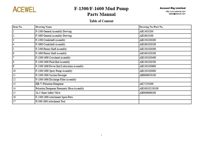
Table of ContentItem No. Drawing Name Drawing No./Part No.1 F-1300 General Assembly Drawing AH130102002 F-1600 General Assembly Drawing AH16010200Assembly AH1301020200 Crankshaft3 F-1300CrankshaftAssembly AH16010201004 F-16005 F-1300 Pinion Shaft Assembly AH13010203006 F-1600 Pinion Shaft Assembly AH1601020200Assembly AH1301020400 Crosshead7 F-1300/1600Assembly AH1301020500EndFluid8 F-1300/16009 F-1300/1600 Power End Lubrication Assembly AH130102060010 F-1300/1600PumpAssembly AH1301020800 SprayDesurger AH0000050100 Suction11 F-1300/1600AssemblyFilterDischarge12 F-1300/160013 KB-75 Pulsation Dampener AK7535020014 Pulsation Dampener Pneumatic Hose Assembly AH10010213010015 JA-3 Shear Safety Valve AH000006020016 F-1300/1600 Attachment Spare PartsToolAttachment17 F1300/1600F-1300/1600 Mud PumpItem No.Qty.Products Name Old Drawing No.New Drawing No.F-1300F-16001 1 FrameAssembly AH36002-01.00 AH1301020100 AH13010201002 1 CrankshaftAssembly AH36002-02.00 (F-1300)AH37002-01.00 (F-1600)AH1301020200 AH16010201003 1 PinionShaftAssembly AH36002-03.00 (F-1300)AH37002-02.00 (F-1600)AH1301020300 AH16010202004 3 CrossheadAssembly AH36002-04.00 AH1301020400 AH1301020400 5 1 FluidEndAssembly AH36002-05.00 AH1301020500 AH13010205006 1 Power end lubrication assembly AH36002-06A.00 AH1301020600 AH13010206007 1 BaseSeat AH36002-07.00 AH1301020700 AH1301020700 8 1 SprayPumpAssembly AH36002-08.00 AH1301020800 AH13010208009 2 BS Name Plate AH13010209 (F-1300)AH37002-03B (F-1600)AH13010209 AH1601020310 1 AttachmentTools AH36002-10.00 AH1301021000 AH130102100011 1 Attachment Spare Parts AH36002-11.00 AH1301021100 AH130102110012 1 DischargeFilterAssembly AH34004-18.00 AH1001021100 AH1001021100 13 2 SealingWasher AH33001-09 AH10010109 AH10010109 14 1 BreatherCap T515-1001.00 T515-1001.00 T515-1001.0015 1 Crane AH36001-10.00 AH1301011000 AH130101100016 1 Crane AH36001-11A.00 AH1301011100 AH130101110017 1 CoverPlate AH36001-12.00 AH1301011200 AH130101120018 1 Gasket AH36001-13 AH13010113 AH1301011319 2 IndicationBoard AH33001-17B(F-1300)AH10010113 AH10010210Item No.Qty.Products Name Old Drawing No.New Drawing No.F-1300F-1600AH33001-17A (F-1600)20 2 Oil Level Indicator AH33001-18.00 AH1001011400 AH100101140022 2 Clean Out Cover (III) AH33001-22.00 AH1001011500 AH100101150023 2 Gasket AH36001-19 AH10010116 AH1001011624 2 CrossheadDoor AH36001-15A (F-1300)AH37001-04 (F-1600)AH13010114 AH1601010425 2 Gasket AH36001-16 AH13010115 AH1301011526 1 Transitionjoint T512-1002 T512-1002 T512-100227 1 ElbowPipe AH33001-30 AH10010212 AH10010212 28 3 RingGasketR44 T58-5002 T508-5002 T508-500229 1 Flange T58-1002 T508-1002 T508-100230 1 KB-75 Pulsation Dampener AH33010-00 AK75350200 AK7535020031 1 JA-3ShearReliefV alve AH33007-00 AH0000060200 AH0000060200 32 2 AdapterNPT3 T510-1002 T510-1002 T510-100233 1 CoverPlateAssembly AH36001-21B.00 AH1301011800 AH1301011800 34 2 QuarterBendNPT3 T511-1002 T511-1002 T511-100235 14 Bolt1/2-13UNCX1 T50-1001 T500-1001 T500-100136 8 Bolt1/2-13UNCX11/2 T50-1017 T500-1017 T500-101737 28 Bolt5/8-11UNCX15/8 T50-1010 T500-1010 T500-101038 16 Bolt1-8UNCX31/4 T50-1013 T500-1013 T500-101339 16 Nut1-8UNC-2B T51-1003 T501-1003 T501-100340 4 Bolt5/8-11UNCX13/4 T50-1008 T500-1008 T500-100841 4 Nut5/8-11UNC-2B T51-1002 T501-1002 T501-1002Item No.Qty.Products Name Old Drawing No.New Drawing No.F-1300F-160042 6 Sign With The Nail 3X10 (GB827) GB827-86 420999050603001000 42099905060300100043 16 SpringWasher27(GB93)GB93-76 42050301127160000042050301127160000044 22 Washer12(GB848)GB848-85 42050103612020000042050103612020000045 28 Washer16(GB848)GB848-76 42050103616020000042050103616020000046 4 SpringWasher16(GB93)GB93-76 42050301016160000042050301016160000047 8 Cross Recess Head Screw M4X16 (GB818) GB818-85 420101050704001606 42010105070400160648 1 Rubber Strip 40X10X5800 14060106100000000014060106100000000014060106100000000049 1 Double Scale Pressure Gauge 60MPa,8700psi 380207192602511514 380207192602511514 38020719260251151450 10 ml Thread Lock Solid Anaerobic Glue 243 170506010100243000 17050601010024300051 As per requirements Adjusting Shim AH36001-23 AH13010119 AH1301011952 8 Flat Gasket 27 (GB95)GB95-85 420501060270100000 4205010602701000002423262122R1R221#13467512#21089Fluid End11#313142824191828272026161517F-1300/1600 Crankshaft AssemblyItem No. Qty. Product Name Old Drawing No. New Drawing No.F-1300 F-16001 2 Main Bearing End Cover AH36001-02.01C.00 AH130101020100 AH1301010201002 1 Main Bearing Set (Right) AH36002-02.01 (F-1300)AH37002-01.01 (F-1600)AH1301020201 AH16010201013 2 SealingWasher AH36001-02.03 AH1301010203 AH13010102034 2 Inner Locking Ring AH36001-02.04 AH1301010204AH13010102045 3 OuterRaceRetainer AH36001-02.05 (F-1300)AH37001-01.03 (F-1600)AH130101020500 AH1601010102006 3 ConnectionRod AH36002-02.02 (F-1300)AH37002-01.02 (F-1600)AH1301020202 AH16010201027 1 LocatingRing(I) AH36002-02.03 AH1301020203 AH13010202038 1 HollowCrankShaft9 1 LocatingRing(II)10 1 BigGearRing AH36002-02.04A.00 AH130102020400 AH130102020400 1112 Piston Nut 1 1/2-8UN AH36002-02.05 AH1301020205 AH130102020512 12 Bolt 1 1/2-8UNX5 1/2 AH36001-02.10D.00 (F-1300)AH37001-01.05D.00 (F-1600)AH130101021000 AH16010101040013 2 Spacer AH36001-02.12 AH1301010211 AH130101021114 1 Main Bearing Set (left) AH36002-02.06 (F-1300)AH37002-01.03 (F-1600)AH1301020206 AH160102010315 2 RetainerRing AH36001-02.14 (F-1300)AH37001-01.07 (F-1600)AH1301010213 AH160101010616 72 Bolt5/8-11UNCX11/2 T50-1018K T500-1018K T500-1018K 17 2 Retainer AH36001-02.15 AH1301010214 AH1301010214Item No. Qty. Product Name Old Drawing No. New Drawing No.F-1300 F-160018 28 Bolt5/8-11UNCX13/4 T50-1008 T500-1008 T500-100819 4 MainBearingBolt AH36001-02.16C AH1301010215 AH130101021520 As per requirements Shim Set AH36001-02.17 AH130101021600 AH13010102160021 2 Bolt5/8-11UNCX4 T50-3004K T500-3004K T500-3004K22 3 EccentricBearing AH36001-02.19.00 (F-1300)AH37001-01.08.00 (F-1600)AH1301010217 AH160101010723 2 MainBearing AH36001-02.20.00 (F-1300)AH37001-01.09.00 (F-1600)AH1301010218 AH160101010824 28 Washer16(GB848) GB848-85 420501036160200000420501036160200000 25 2 Bolt5/8-11UNCX43/4 T50-3006K T500-3006K T500-3006K26 40m LockWireΦ1.5 (GB343) GB343-82 040101010150600000 04010101015060000027 3m LockWireΦ3 (GB343) GB343-82 040101010300600000 04010101030060000028 90ml Loctite243 Loctite 243170506010100243000 170506010100243000R1 1 Big Gear Ring (Piece Together) AH36001-02.10B.00 (F-1300)AH37001-01.05B.00 (F-1600)AH130101021900 AH160101010900R2 12 Bolt11/2-8UNX7 T50-2033 T500-2033 T500-2033F-1300 Pinion Shaft AssemblyItem No.Qty Products Name Old Drawing No.New Drawing No.F-1300F-16002″×2″×11 3/8″ AH36002-03.01 AH1301020301 AH1301020301 1 1 KeyAH1301020302 AH1601020201(F-1300)2 1 PinionShaft AH36002-03.02AH37002-02.01 (F-1600)WearRing AH36001-03.03 AH1301010303 AH1301010303 Seal3 2 OilCover AH36002-03.03B AH1301020303 AH13010203034 2 End5 2 Gasket AH36001-03.05 AH1301010305 AH13010103056 2 Gasket AH36001-03.06 AH1301010306 AH1301010306Sleeve AH36001-03.07B AH1301010307 AH13010103077 2 Bearing8 2 RaceRetainer AH36002-03.05B AH1301020305 AH1301020305Washer AH36001-03.12B AH1301010309 AH13010103099 2 Seal10 2 Oil Gathering Box AH36001-03.13B.00 AH130101031000 AH1301010310003/8 T50-1019 T500-1019 T500-10191/2-13UNCX1Bolt11 247/8-9UNCX2 T50-1027 T500-1027 T500-102712 16 Bolt13 2 Oil Seal 9.125”X10.375”X0.625” AH36001-03.08A AH1301010311 AH1301010311AH36001-03.09 AH1301010312 AH1301010312(N.W.)4G32844H14 2 Bearing(GB93)GB93-87 420503011221600000 420503011221600000 15 16 Washer22(GB93)GB93-87 420503011141600000 4205030111416000001416 24 Washer17 1 Flange AH36001-03.11 AH1301010313 AH13010103133/4 T50-2003 T500-2003 T500-200318 3 Bolt5/8-11UNCX1Washer GB93-87 420503011161600000 420503011161600000 19 3 Spring11F1300/1600 Cross Head AssemblyItem No.Qty.Products Name Old Drawing No.New Drawing No.1 1 Crosshead AH36002-04.01 AH13010204012 1 UpperSlide AH36001-04.02 AH1301010402Unit AH36001-04.03A.00 AH1001010417003 8 Gasket4 2 Adjusting Pad AH36001-04.04AH1301010403AH1301010404 5 1 Packing Box AH36001-04.05AH1301010405 6 1 Oil Seal Ring AH36001-04.21φ190×3.55 (GB3452.1) GB3452.1-82 5303010119000355077 1 O-ring5”X6.25”X0.625” AH36001-04.08A AH13010104068 2 Two-lipSealSpring AH36001-04.13 AH13010104079 1 Locking10 1 SplashGuard AH36001-04.10 AH1301010408Rod AH36001-04.11 AH130101040911 1 ExtensionPin AH36002-04.03 AH130102040312 1 Crosshead13 1 O-ringφ125×7(GB3452.1)GB3452.1-82 5303010112500700071/2 T50-3010 T500-301014 8 Bolt3/4-10UNCX2Gasket AH36001-04.15 AH130101041115 1 Sealing16 1 O-ringφ160×7(GB3452.1)GB3452.1-82 530301011600070007Slide AH36001-04.17 AH130101041217 1 LowerGuide AH36002-04.04 AH130102040418 1 CrossheadPin19 1 Cross Head Bearing AH36001-04.19 AH1301010414AH1001010405NPT3/8″×2 AH33001-04.07Joint20 2 Pipe1/4 T50-2018K T500-2018K21 2 Bolt1-8UNCX212Item No.Qty.Products Name Old Drawing No.New Drawing No.1/2 T50-2019K T500-2019K1-8UNCX222 6 BoltPlate AH36002-04.02 AH130102040223 8 Locking24 4 Bolt3/8-16UNCX1 T50-1021 T500-10211-8UNCX21/2 T50-3013K T500-3013K25 8 Screw(GB93) GB93-87 42050301110160000010Washer26 4 Spring27 As per requirements Zinc-coated Wire φ1.6 (GB4240) 040104030160000800 040104030160000800243 243 170506010100243000 30 Loctite1314F-1300/1600 Fluid End AssemblyItem No.Qty.Products Name Old Drawing No.Drawing No.Assembly AH36002-05.01.00 AH130102050100CylinderHydraulic1 3Flange AH36001-05.02 AH1301010502Head2 3CylinderHead AH36001-05.03 AH1301010503 Cylinder3 3Assembly AH36001-05A.04.00 AH130101050400 Board4 3Plug(Lower) AH36001-05A.05.00 AH130101050500GuidesRod5 3V alvePlug AH36001-05A.06.00 AH130101050600 Head6 3CylinderPlate AH36001-05A.07 AH1301010507 Positioning7 3SealingHeadRing AH36001-05.08 AH1301010508 Cylinder8 3Manifold AH36001-05.09 AH1301010509 Discharge9 1Spring AH33001-05.16A AH0000010110 6 V alveφ95×5.3 (GB3452.1)GB3452.1-82 53030101095005300711 3 O-ringThrough-hole AH36001-05.12A.00 AH0000020300API7Assembly12 6 V alve13 3 V alve Cover Sealing Ring AH36001-05.13 AH130101051014 3 V alveCover AH36002-05.02 AH1301020502Seal AH36001-05.15 AH130101051215 6 CylinderLinerPlate AH36002-05.03 AH130102050316 3 WearingFlange AH36001-05.17 AH130101051417 3 CylinderLinerLinerGland AH36001-05.18.00 AH130101051500 18 3 CylinderRod AH36002-05.05 AH130102050419 3 PistonNPT3/8 AH36002-05.04.00 AH130102050500 20 3 Adapterφ200×7 (GB3452.1)GB3452.1-82 53030101200007000721 3 O-ring22 3 Cylinder Liner Lock Ring AH36001-05.22 AH13010105181523 3 Bi-MetalLiner AH130102051200CylinderAssembly AH36002-05.06.00 AH13010205060024 3 Clamp26 3 ElbowNPT3/8-M22X1.5 AH36002-05.08 AH1301020507Cover AH36001-05.27 AH130101052027 3 CylinderEndPiston AH36002-05.09.00 AH13010205080028 3 British7/8-9UNCX2 T50-1027 T500-102729 18BoltNPT1/2-M22X1.5 AH36002-05.10 AH130102050930 3 AdapterConnectorNPT1-NPT1/2 AH36002-05.11 AH1301020510Connector31 3 Right-angleManifold AH36002-05.12A.00 AH13010205110032 1 SuctionAH130101052300 33 4 Gasket Unit AH36001-05.33A.00BackupRing AH36001-05.39 AH100101052734 3035 3 V alve Rod Guide (Upper) AH33001-05.12 AH1001010510Bolt11/2 T50-7002 T500-70021/2-8UNX10ArmedDouble36 161/2-8UN T51-2001 T501-20011Nut37 4438 3 Dam-board AH33001-05.14 AH10010105123/8-16UNCX3/4 AH35003-05.04 AH050102050939 12Bot(GB3452.1)GB3452.1-82 53030101041203550741.2X3.5540 3 O-ring11/2-8UN T51-3003.0 T501-303.0Nut41 3 PistonΦ185X7 (GB3452.1)GB3452.1-82 53030101185007000742 3 O-ringT505-100643 1 Inhalation of The Blocking Plate T55-1006Φ345X7(GB3452.1)GB3452.1-82 53030101345007000744 3 O-ringFlange(I)AH33001-05.39 AH100101052545 2 Suction(II)AH33009-05.03 AH1001020509Flange46 1 Suction1647 361-8UNC T51-1003 T501-1003Nut1/2 T50-1023 T500-10231-8UNCX3Bolt48 24φ1.6×1830 (GB4240) 040104030160001900 040104030160001900WireSteel49 1 Stainless(JB1887)JB1887-77 140507011301008530C-13X1W-850Hose50 3 WithholdTypeAssembly51 2 Screwed Plug NPT 1 1/2 T56-1007 T506-100752 12 Double Armed Bolt 1 1/2-8UNX22 1/4 AH36002-05.01.00A AH1301020513243 243 170506010100243000glueT ai53 Le1-8UNCX41/4 T50-1024 T500-102454 12Bolt55 3 Hose Clip 3 (Q/ZB251)Q/ZB251-77 06140103075000000056 2 Discharge Blocking Plate T55-1008T505-1008 Chamber AH33001-05.35A.00 AH000005010057 SuctionAir1729(乐泰609)313621543445511:3H44504135434042383755398193210403639H331541828463729524931098282710182810864811472751125312411514368839343472338301641722202552202121192021232418F-1300/1600 Power End Lubrication AssemblyItem No.Qty.Products Name Old Drawing No.Drawing No.1 1 Square Key 3/16×3/16×1 T516-2001 T516-2001Assembly AH34007-06.01.00 AH080102060100GearOil2 1Pump3/8 T511-3002 T511-30021/4×NPT3 2NPT90°ElbowA12(GB5650) GB5650-85 520902540320120100Hollow4 2Bolt5 8 Socket Head Cap Screw 5/16-18UNCX1 5/8 T50-3003 T500-30036 2 Pipe Joint A16 (JB/ZQ4410) JB/ZQ4410-86 520901010350040040A8(JB/ZQ4410) JB/ZQ4410-86 520901010350050050JointPipe7 31/4×NPT1/4 T511-3001 T511-3001NPTElbow8 1490°Φ8×305 (GB1527) 051102010080010002 051102010080010002PipeCopper9 110 17 Pipe Joint A8 (JB/ZQ4408) JB/ZQ4408-86 520901010330050050Assembly(II)AH33001-06.40 AH1001010611Connector11 1(JB/ZQ4408) JB/ZQ4408-86 520901010330040040A16Joint12 2 PipePipeΦ16×686 (GB1527) 051102010160015002 05110201016001500213 1 CopperΦ16×331 (GB1527) 051102010160015002 05110201016001500214 1 CopperPipe15 2 Three Pipe Clamp AH34007-06.02.00 AH080102060200Joint AH36001-06A.10 AH1001010608Pipe16 2 45°PipeΦ10×838 (GB1527) 051102010100010002 05110201010001000217 1 CopperΦ12×305 (GB1527) 051102010120010002 051102010120010002Pipe18 1 CopperAH050102060400 Φ8 AH35003-06.04.0019 13ClampPipeΦ8×762 (GB1527) 051102010080010002 05110201008001000220 3 CopperPipePipeΦ8×508 (GB1527) 051102010080010002 05110201008001000221 2 CopperΦ8×229 (GB1527) 051102010080010002 051102010080010002Pipe22 2 Copper19Item No.Qty.Products Name Old Drawing No.Drawing No.NPT1/4” T56-1002 T506-1002Plug23 5 PipePipeΦ8×915 (GB1527)051102010080010002 05110201008001000224 1 CopperPipeΦ8×1194 (GB1527)051102010080010002 05110201008001000225 1 CopperPipeΦ8×10¹⁶ (GB1527)051102010080010002 05110201008001000226 1 Copper(I)AH33001-06A.11 AH100101060727 1 ConnectorAssembly28 2 Pipe Joint A10 (JB/ZQ4408) JB/ZQ4408-86 520901010330010010(I)AH35003-06.01.00 AH050102060100Clamp29 4 Pipe(GB5651) GB5651-85 520902551280120100A1230 2 Gasket1/4-20UNCX3/4 T50-1007 T500-100731 4 BoltNipple AH36001-06.10 AH130101060132 2 FlowΦ12×610 (GB1527) 051102010012010002 051102010012010002Pipe33 2 CopperΦ8×813 (GB1527) 051102010080010002 05110201008001000234 2 CopperPipe(GB5628.1) GB5628.1-85 520901010050050050A835 2 PipeJointAH050102060200 Φ8 AH35003-06.02.00Card36 3 DualΦ10×195 (GB1527)051102010010010002 05110201001001000237 1 CopperPipeΦ8×1956 (GB1527)051102010080010002 051102010080010002Pipe38 1 CopperPipeΦ8×2311 (GB1527)051102010080010002 05110201008001000239 1 CopperPipeΦ8×1600 (GB1527)051102010080010002 05110201008001000240 1 CopperΦ8×1245 (GB1527)051102010080010002 051102010080010002Pipe41 1 CopperNPT1/4-NPT1/4 T512-3001 T512-300142 1 PipeJointUnit AH33001-06.06A.00 AH10010106040044 1 Gasket45 1 Stand AH36002-06.01C AH13010206020046 1 Pipe Joint A10 (GB5628.1) GB5628.1-85 52090101005001001020Item No.Qty.Products Name Old Drawing No.Drawing No.(GB93) GB93-76 4205030110816000008Washer47 8 Spring(YYFJ-L120) YYFJ-L20 512604900000032002 48 1 OverflowV alve(GB93) GB93-87 4205030110816000008Washer49 4 Spring50 1 2S Gear Oil Pump 51260101003100000051 1 Double Scale Pressure Gauge M14x1.5 (Y-60Z) Y-60Z 38020205116000602152 4 Pipe Joint A12 (JB/ZQ4408) JB/ZQ4408-86 520901010330020020Assembly AH36001-06A.33.00 AH10010106100053 1 OilFilterRubber 609(680) 170506010100609000 54 CylindricalFixingBlock AH36001-06C.01 AH100101061355 2 LocatedF-1300/1600 Spray Pump AssemblyItem No. Qty .Products NameOld Drawing No.Drawing No.1 1 Shield AH36002-08.01.00AAH130102080100AH1301020803002 1 Belt PulleyAH36001-08B.02 AH13010108023 1 Support Assembly AH333009-08.02.00 AH1001020802004 1 Short Circuit Z1″-G1″ AH36001-08.02 AH10010108045 1 Adapter Connector Z1″ AH36001-08B.04 AH10010108056 1 Adapter Connector G1″-M33×2 AH36001-08.03 AH1001010806 71Adapter Connector ZG2-1/2″ AH33001-08A.07 AH10010108078 1 Short CircuitZG2 1/2″-Z2 1/2AH36001-08C.04AH10010108089 1 Flexible Pipe Φ22×Φ37 140501010220100000 140501010220100000 10 2 Pipe Joint Φ22×Φ37 AH33001-08.18.00 AH10010108090011 3 90° Elbow Z1” AH33001-08.16 AH1001010810 12 2 Junction Plate AH33009-08.03AH100102080313 1 Water TankAH36001-08C.01.00 AH13010108040014 1 Tank Cover AH36001-08C.02.00 AH100101081300 15 1 Adapter Connector NPT2 1/2″ T513-1004 T513-1004 16 2 GasketAH36001-08B.09AH100101081417 2 Flange Z1″ AH36001-08B.10 AH1001010815 18 2 Fastening Screw M8×25(GB73) GB73-85 420103028308002500 19 2 Bead Apex A-3708(GB1171) 140301012037080000 140301012037080000 20 2 Pipe Clamp NO:3061401010380000000 06140101038000000021 1 Flexible Pipe Φ38×Φ53 140501010380305300 140501010380305300Item No.Qty.Products Name Old Drawing No.Drawing No.22 1 90° Elbow ZG2 1/2″52020705040065000223 4 Bolt 5/8-11UNCX1 1/8 T50-1029 T500-102916(GB93) GB93-87 42050301116160000024 4 SpringWasher(GB96) GB95-85 4205010461601000001625 4 FlatWasher5/8 T50-1004 T500-100426 4 Bolt1/2-13UNCX127 12 Spring Washer 14 (GB93) GB93-87 42050301114160000028 4 Flat(GB96) GB96-85 42050104614010000014Washer1/2-13UNCX21/4 T50-1005 T500-100529 8 Bolt1/2-13UNC T51-1001 T501-100130 8 Nut31 1 Centrifugal Spray Pump AH36001-08B.11.00 AH10010108160032 1 Stainless Steel Internal Thread Ball Valve G1" 441305011104164025 44130501110416402533 1 Support AH36002-08.02.00 AH1301020802001 2F-1300/1600 Suction Desurger AssemblyItem No.Qty.Products Name Old Drawing No.Drawing No.Assembly AH33001-05.35A.00 AH0000050100ChamberAirSuctionCapsule AH33001-05.35A.02 AH00000501011 12 1Cover AH33001-05.35B.03 AH0000050102 End812115647715101413916213R2R1F-1300/1600 Discharge Filter AssemblyItem No.Qty.Products Name Old Drawing No.Drawing No.Shell AH34004-18.01 AH10010211011 1AH100101190200 The Filter Assembly AH36001-19.01.002 1165x7 GB3452.1-82 530301011650070007O-ring3 14 8 Double Armed Bolt 1 1/2-12UNF/1 1/2-8UNCX5 1/4T50-6007 T500-600711/2-8UN-2B T51-2001 T501-2001Nut5 8KB-75 Pulsation Dampener AssemblyItem No.Qty.Products Name Old Drawing No.Drawing No.Drawing AK75350200GeneralRing T508-5001 T58-50011 1 Backing2 1 BottomBlug AK75350101 AH33002-02Bag AK7535010200 AH33002-03.003 1 AirAssembly AK7535020100 AH33010-01.004 1 Shell5 1 Cover AK75350202 AH33010-02AT511-2001 1/4″ T511-20016 1 3Way1/4″ AK75350106AH33002-07Connector7 1 AdapterCoverAssembly AK7535020300 AH33010-03.00Gauge8 1 PressureV alve AK7535010001 PJC1-L8Release9 1 Air10 1 Double Scale Pressure Gauge 0-25MPa NPT1/4 380202052250006020 Y60V alves AK7535010002 JZR3-L8Stop11 1 AngleRing T514-1001 T514-100112 1 BackupR1 12 Double Armed Bolt 1 1/2X4 3/4 T500-6002 T50-60021/2-8UN T501-2001 T51-20011R2 12 NutR3 8 Double Armed Bolt 1 1/4X4 1/4 T500-6003 T50-60031/4-8UN T500-2002 T50-2002R4 8 Nut1Pulsation Dampener Pneumatic Hose AssemblyItem No.Qty.Products Name Old Drawing No.Drawing No.Pulsation Dampener Pneumatic Hose Assembly AH33001-31.10.00A AH100102130100G5/8″ AH33001-31.10.01AAH100102120101 Nut1 1AH100102120102Joint AH33001-31.10.02A2 1Seal3 1 C type Connector Hose M14×1.5 JB1887-77 520901050030080084AH100101210703Connector AH33001-31.10.034 1AdapterAH100101210704Gaskets AH33001-31.10.045 1AH100101210705Plug AH33001-31.10.056 1Pipe13122115192014A - AJA-3 Shear Relief ValveITEM NO.QTY.PRODUCTS NAME OLD DRA WING NO.DRA WING NO.Shear Safety V alve AH33007-00 AH0000060200Connector AH33003-01 AH00000601011 1AdapterFlange AH33003-02 AH0000060102Bead2 1PistonAssembly AH33003-03.00 AH0000060103003 1Body AH33003-04 AH0000060104V alve4 1PistonRod AH33003-05 AH00000601055 1Pad AH33003-06 AH0000060106Crash6 1Pin AH33003-07 AH0000060107Cylindrical7 1ElasticSpring AH33003-08 AH00000601088 1LockingSafetyV alve AH33003-09 AH00000601099 1Plate AH33003-10 AH0000060110Shear10 1Pin AH33003-11A AH000006011111 1ShearNameplate AH33003-12B AH0000060201Warning12 1Roll AH33003-13 AH000006011313 1PinRing AH33003-14 AH0000060114Baffle14 2CableSteelNameplate AH33003-15A AH000006020215 1Cotter4×26 GB91-86 420703020504002600 16 1M4 GB41-86 420402080040200000 Nut17 2M4×16 GB67-85 420101021104001600 18 2Screw3/8-16UNCX41/4 T50-1016 T500-1016Bolt19 1Nut3/8-16UNC T51-1005 T501-100520 1M3×8 GB67-86 420101020703000800 21 4ScrewF-1300/1600 Attachment Spare PartsItem No.Qty.Products Name Old Drawing No.Drawing No.Parts AH36002-11.00 AH1301021100SpareAttachment9.125”x10.375x0.625”AH36001-03.08A AH1301010311SealOil1 2φ190X3.55 (GB3452.1)GB3452.1-82 530301011900035000O-ring2 3O-ringφ160X7 (GB3452.1)GB3452.1-82 5303010116000700073 35”x6.25”x0.625”AH36001-04.08A AH1301010406SealDouble-lip4 6O-ringφ95X5.3 (GB3452.1)GB3452.1-82 5303010109500530075 3AH1301010510 V alve Cover Seal AH36001-05.136 3Seal AH36001-05.15 AH1301010512Liner7 6CylinderAH13010105088 3Cylinder Head Seal Ring AH36001-05.08φ200X7 (GB3452.1)GB3452.1-82 5303010120000700079 3O-ringφ41.2X3.55 (GB3452.1)GB3452.1-82 53030101041203550710 3 O-ringO-ringφ185X7 (GB3452.1)GB3452.1-82 53030101185007000711 3φ345X7 (GB3452.1)GB3452.1-82 53030101345007000712 3 O-ring61/2L T54-01.32 T504-132.0013 3 RubberAH00000203010314 6 Rubber V alve AH36001-05.12A.0315 3 Backing Ring R44 T58-5002 T508-500216 1 Backing Ring R39 T58-5001 T508-5001Pad AH33003-06 AH000006010617 1 CrashAssembly AH33003-03.00 AH00000601030018 1 Piston19 1 Gasbag AH33002-03.00 AK7535010200Pin AH33003-11A AH0000060111Shear20 10Washer AH33001-09 AH1001010921 2 SealItem No.Qty.Products Name Old Drawing No.Drawing No.Seal AH36001-04.21 AH1301010405 22 3 Oilφ125X7 (GB3452.1)GB3452.1-82 53030101125007000723 3 O-ringAH0000050101 24 1 Capsule AH33001-05.35A.02F1300/1600 Attachment ToolItem No.Qty.Products Name Old Drawing No.Drawing No.AH1301021000 Tools Attachment AH36002-10.00LiftingTool AH36002-10.01.00 AH130102100100LinerCylinder1 1HeadRod AH36001-17.02A AH100101210100Cylinder2 13/8” AH36001-17.04 AH10010121082Sleeve3 12“ AH36001-17.05 AH1001012109Sleeve4 15/8” AH36001-17.06 AH13010116023Sleeve5 11/2” AH36001-17.08 AH13010116031Sleeve6 1Union AH36001-17.09 AH13010116047 1Reducer8 1 Extension Bar 19 5/8” AH36001-17.10 AH13010116059 1Bar8” AH36001-17.11 AH1001012110ExtensionConnector1” AH36001-17.12 AH100101211110 1 Adapter24” AH36001-17.13 AH1001012112BarReinforcing11 1SH1/2 JB560-64 390101010100500000Hoist12 1 HandChainPump70Mpa PSH-Ⅱ512605040000117000Hydraulic13 1 Manual14 1 Air Bag Is Inflated Hose Assembly AH33001-31.10.00A AH100102130100AH13010116060015 1 Hydraulic Pull V alve AH36001-17.15.00B16 1 Packing Guide Sleeve AH36001-17.24 AH1301011607TaperSleeve AH36001-17.17 AH130101160817 1 TransitionAH130101160918 1 Pressure Sleeve AH36001-17.18AH130101161000 19 1 Long Sleeve AH36001-17.20.00Extractor AH36001-17.22.00 AH130101161200Board20 1 PlugItem No.Qty.Products Name Old Drawing No.Drawing No.Screw AH36001-17.25 AH1301011613 21 1 ShortSeat AH37005-08.01.03 AH1301011614 22 1 Hanging。
1. Enclosed Impeller Even wear components.Balanced hydraulic design for extended and even wear life of all components.28% High Chrome 650+ Brinell hardness, impeller, wear plate and casing. Back pull out design.2. Slurry Mechanical SealDual Seals of Silicon Carbide vs. Silicon Carbide running without the need for flush water.The motor is further protected by a labyrinth seal and a seal relief port.3. Premium Efficiency MotorInverter duty, air filled, copper wound/formed motor. Class H insulation.Extended run dry capabilities, minimizes the cost of operation.4. Replaceable FlangesFlanges are made from mild steel to prevent cracking the high chrome fittings.Horsepower................................................................................................15 – 1500 HP 15 – 150 HP ( SBLH Series )Discharge Size............................................................................................3” – 20”3” to 8” ( SBLH Series )Performance RangeCapacity................................................................................100 – 20,000 US GPM 100 – 4,500 US GPM ( SBLH Series )Head ......................................................................................50’ – 350’ TH10’ – 160’ TH ( SBLH Series )Solids Handling..........................................................................................1” to 5” Particle Size1.375” to2.50” Particle Size (SBLH Series)Motor NomenclatureType, Speed, HZ ..................................................................TENV Air Filled / 890-1180 / 60 HZ 350 to 1780 RPM / 50 HZ Voltage, Phase......................................................................480 V. / 3 Phase / 1.2 Service Factor 240 / 575 / 2400 / 4160 Volt Insulation ..............................................................................Class H Cable Length........................................................................33’ Standard Cable Length as RequiredMaximum Run Time in Air...................................................................... 1 Year Maximum Water Temperature................................................................180°F. +Water Jacket to Handle Hotter Temperatures Operation Mode ........................................................................................Manual or SnoreVariable Speed Drive / Float Controls Materials of ConstructionCasing....................................................................................28% High Chrome 650+ Brinell Hardness 15/3 White Iron Impeller..................................................................................28% High Chrome 650+ Brinell Hardness 15/3 White Iron Wear Plate............................................................................28% High Chrome 650+ Brinell Hardness 15/3 White IronShaft ......................................................................................416 Stainless SteelMotor Housing......................................................................Cast Iron 3/8” Minimum Thickness Fasteners ..............................................................................316 Stainless Steel Impeller Type..............................................................................................EnclosedSemi-Open - Recessed ( SBLH Series )Mechanical SealUpper Seat............................................................................Silicon Carbide Upper Rotator ......................................................................Silicon Carbide Lower Rotator......................................................................Silicon Carbide Lower Seat............................................................................Silicon Carbide Elastomers............................................................................Viton Labyrinth Seal......................................................................Cast Steel316 Stainless Steel / BronzeBearings......................................................................................................Permanently Lubricated DoubleAngular Contact 100,000 Hour B-10 LifeAccessories ................................................................................................Discharge Hose / Variable Speed Drives / Urethane Coating / Elbows in Steel or High Chrome / Control Panels / Moisture and Thermal Protection / Float Controls / Rafts.FEATURESAPPLICATIONS1.Bottom Ash2.Tailings Ponds3.Sand / Gravel / Taconite4.Clean Out Sumps5.Coke Pits6.Dredging7.Coal Pile Runoff 8.Slag Pits / Mill Scale 9.Boiler Blow Down 10.Lime Slurry 11.Red Mud Recovery12.Thickener Drain13.Precipitation Thickener 14.API SludgeSPECIFICATIONSHEAVY DUTY HIGH CHROME SLURRY PUMPThe heaviest duty submersible pump in the industry.Built to handle the most severe slurryapplications where others fail.SPECIFICATIONSSTANDARDOPTIONSFactory–4432VentureAvenue•Duluth,MN55811•218.722.9904•Fax218.722.2826••email:***************©GPM,INC.2002SUBMERSIBLE SBEW SERIES。
f1600泥浆泵织衬衫(638/639类)和化纤制裤子(647/648类)重新设置数量限制,欧盟也紧随其后,对我两个类别的纺织品设限。
持续的中美以及与欧盟关于纺织品贸易的摩擦都将使我国纺织服装业的出口蒙受损失。
随着《纺织品出口临时管理办法》的发布,我国已妥善解决了与欧盟的纺织品贸易争端,将对25年月日开始征收出口关税的48项纺织品中的74种纺织品提高出口关税税率,该《管理办法》是否适用于美国设限产品,还视磋商情形而定。
但据商务部官方说明,由于美方一再对我国单方面设限,且给予的额度较小,致使目前设限产品数量已所剩不多,棉制针织衬衫、棉制裤子等敏感紧俏类别中国海关统计的清关率已近%。
铁路运输业保持平稳增长 5月份以来,尽管受运力紧张、线路施工、水害断道等因素的影响,铁路运输业依然继续保持了平稳增长的态势,客货运输主要指标再创历史同期最高纪录。
5月份,铁路货物发送量完成9434.3万吨,同比增长6.5%,增速比去年同期高出.7个百分点。
其中,煤炭、粮食、化肥和农药运量分别完成8952.万吨、96.3万吨、64.4万吨,同比分别增长7.3%、3.8%和27.4%。
铁路客运在"五一"黄金周的拉动下,完成旅客发送量9294.7万人,同比增长5.%。
在当前铁路运输快速增长与铁路运力紧张的矛盾日益突出的形势下,我国铁路建设已迎来了新一轮的建设高潮。
为保障铁路建设所需资金来源,加快铁路投融资体制改革迫在眉睫。
目前,我国铁路投融资体制改革提出了"政府主导,多元化投资,市场化运作"的总体思路,即政府投资为主导,充分发挥各方投资铁路的积极性,形成多元化投资格局,并按照法律法规和市场规则,组建规范的合资铁路,负责建设和经营管理。
按照该指导思路,我国铁路投融资体制改革将主要集中在以下三个方面:一是加大中央政府与地方政府合作建设铁路的力度,改变单纯由中央【f1600泥浆泵】产品:【f1600泥浆泵】产品简介:NL系列泥浆泵系单级单吸立式离心泵,主要部件有蜗壳、叶轮、泵座、泵壳、支撑筒、电机座、电动机等组成。
BOMCO F-1300/1600钻井泵操作手册AH13010100CZAH16010100CZ2005年12月前言感谢您购买和使用宝鸡石油机械有限责任公司生产的F系列钻井泵。
F-1300与 F-1600两种规格的钻井泵外形尺寸、机架和液力端相同,只是动力端的轴承和齿轮副不同。
为方便用户,本操作手册同时介绍这两种泵。
F-1300/1600钻井泵操作手册是提供给用户的一套完整资料。
书中提供了准确而简明的数据及操作要领,供钻井泵的操作人员、现场维修人员和技术服务人员查阅。
由于篇幅限制,不可能面面俱到。
但只要严格执行F-1300/1600钻井泵操作手册提供的操作规范,相信可以保证钻井泵有效的工作时间,延长设备的使用寿命。
所有规范和数据都是根据工程设计编制的,应在各项维护和修理作业时严格遵守。
有关F系列泵配套厂家生产的设备,在使用和维修时则以制造厂家的资料为准。
本操作手册如有不完善之处,恳请用户提出宝贵意见和建议。
1 安全准则以下列出了与F-1300/1600钻井泵绞车密切相关的一般安全预防措施。
这些安全预防措施与一些特殊的过程毫不相关并且在操作手册以后的章节中不再出现。
在操作该设备的过程中,操作者必须掌握和运用这些推荐的预防措施。
具体的特殊的预防措施都包含在说明书的警示中。
1.1 合格的人员只有被授权的合格人员才能操作该设备。
1.2 防护设备操作人员都必须穿戴防护服、防护帽、防护鞋及其它的防护设备等。
在钻井作业中,如遇有毒有害气体逸出,操作人员在作业时还必须配戴防毒设备。
1.3 安全习惯安装、操作、拆卸和维护该设备时,好的全面的安全习惯必须随时遵守。
该设备的拥有者/操作者的职责就是建立好的安全习惯、人员的培训和安全习惯的强制遵守。
1.4 设备的操作操作者只有通读该设备的操作手册并且完全熟悉所有操作控制、功能后才可进行操作。
1.5 未被授权人员当操作、维护或运行该设备时,未被授权的人员应当远离。
1.6 可见度当可见度不高时,不允许操作该设备。
目录前言 (2)第一章安装、使用、保养 (3)RS-F1600/1300钻井泵外形图 (4)1 技术规范及性能参数 (5)2 结构特点 (7)3 新泵的安装 (8)4 泵的起动及操作 (11)5 润滑 (13)6 喷淋泵装置 (14)7 保养 (15)8贮藏 (17)9日常维护保养一览表 (18)第二章维护手册 (20)1动力端的维护 (21)2 动力端零件的装配 (22)3液力端维护 (29)4液力端零件的装配 (30)5可能发生的故障和排除方法 (35)第三章零件目录 (36)1 零件目录图纸清单 (37)2 随机工具 (53)3 随机备用件 (55)前言本说明书为了帮助用户对钻井泵有所了解和给钻井泵的操作者和修理工提供指导,就RS-F1300/1600钻井泵的技术规范、结构特点、安装、使用、维护和拆卸等方面分别作较详细的介绍,正确使用本说明书将有助于保证泵的正常运行,但由于篇幅的局限,不可能把每一个一般性的技术问题都一一说明得十分清楚。
安全警示为了防止人身伤害,所有的维修及检查都应在停泵后再进行。
应将泵的发动机上的停机开关关上、安全手柄处于正确的位置再对泵进行检修。
应使用正确的方法对泵进行维修、调节、检查等操作。
在泵运行过程中,所有的安全装置如安全阀、管汇等,必须调整好并处于良好的工作状态。
第一章安装、使用、保养安装、使用、保养1 技术规范及性能参数1.1 技术规范1.2 性能参数(取机械效率η=90%,充满系数α=100%,容积效率100%)2 结构特点2.1动力端泵机架为钢板焊接结构,传动轴和曲轴轴承座系铸钢件,粗加工后与机壳组焊,在曲轴轴承座处采用筋板加强结构,焊后退火以消除内应力,钢性好强度高。
2.1.1曲轴为合金钢铸件。
曲轴上分别装有大齿圈、连杆、轴承等。
大齿圈齿形为整体人字齿,大齿圈内孔与曲轴为过盈配合,并用螺栓、防松螺母紧固。
连杆大端通过单列短圆柱滚子轴承分别安装在曲轴的三个偏心拐上,小端通过双列长圆柱滚子轴承安装在十字头销上。
F1300DB MUD PUMP PACKAGE泥浆泵组操作手册Instruction manual高原石油装备有限责任公司HIGHLAND PETROLEUM EQUIPMENT CO.LTDContents1. General (1)综述2. Technical Parameters (1)技术参数3. Structure Description (1)结构描述4. Installation and Adjustment (1)安装及调节4.1 Installation of Transmission Device (2)传动装置的安装4.2 Coplanar Inspection of Belt Pulley (2)皮带轮的同平面检验4.3 Adjustment of V-belt Tension (2)V带拉紧装置的调节4.4 Tighten of Joint Bolts (3)连接螺栓的紧固4.5 Installing Charging Pump System (3)安装灌注泵系统5. Installation of other accessories (3)其他附件的安装6. About YZ08/ YZ08A DC Motor (3)YZ08/ YZ08A直流电机1.General综述F1300DB mud pump unitization can be used in oil and gas exploration and development site. It is ideal equipment for mud circulation of heavy-duty drilling rig.F1300DB泥浆泵组用于石油天然气勘探开采。
是大型钻机泥浆循环的理想设备。
The F1300DB mud pump unitization has features with simple construction, reliable performance, convenient maintenance, compact volume and easy transportation.F1300DB泥浆泵组操作简单、性能稳定、维护方便、结构紧凑,易于运输。
F-1300/1600机泵组五十九使用维护手册BC136205-00SM012006年07月目录第一章概述 (1)1特点 (1)2型式与基本参数 (1)第二章结构特征 (2)第三章油路总成 (2)1润滑方式 (2)2润滑油(链条箱) (2)3油路总成 (3)第四章润滑系统的维护 (3)第五章设备的安装与调整 (4)第六章其它设备的维修保养 (4)第七章F-1300/1600泵一年备件及易损件推荐清单 (4)第八章F-1300/1600机泵组五十九零件目录 (4)图一:F-1300/1600机泵组五十九(BC136205-00) (6)图二:传动装置(BC136205-0100) (9)图三:油路总成(BC136205-0300) (11)图四:压力表座及安全阀接管(BC000024-0300) (14)第一章概述1 特点F-1300/1600机泵组五十九,可用于石油天然气勘探开发钻井现场。
它是大型钻机泥浆循环的理想设备。
本泵组具有结构简单、使用可靠、维修方便、占地面积小、搬迁成本低等特点。
2 型式与基本参数2.1 型式:后置式单台交流变频电机驱动、链条传动。
2.2 F-1300/1600泥浆泵的基本参数;额定功率: 969kW(1300HP)/1193kW(1600HP)冲程: 305mm额定冲数: 120r/min齿轮速比: 4.206吸入口: 12″排出口: 5″缸径、排量与压力注机械效率90%容积效率100%2.3 YP2 423 L6-6H交流变频电机额定功率1200kW额定转速1000r/min2.4 链条传动链条型号24S-7×176链轮齿数 29/572.5 外形尺寸及重量外形尺寸:见附图重量: 35535kg第二章结构特征单台YP2 423L6-6H交流变频电机置于F-1300/1600泵后部的公共大底座上作为动力,通过球笼万向轴、链条传动驱动钻井泵。
链条箱采用密闭型式,电动润滑油泵强制润滑,并配套了电动喷淋泵。
F1300/1600钻井泵使用说明书AH36001-SMAH37001-SM2003年12月前言F-1300/1600钻井泵使用说明书是提供给用户的一套完整资料。
编写这些资料的目的是为了给予用户准确而简明的数据及操作要领,而这是进行调试及维修所必须的。
本说明书供给为全面熟悉钻井泵的操作者、现场维修人员和技术服务人员使用。
它不打算也不可能在这有限的篇幅内将每个可能遇到的情况都提到,但用户往往可以从中获得良好而满意的机械操作方法和安全可靠运行的预防措施。
F-1300钻井泵和F-1600钻井泵的外形尺寸、机架和液力端相同,只是动力端的轴承和齿轮副不同。
为方便用户,本说明书同时介紹这两种泵。
所有规范和数据都是根据工程设计编制的,应在各项使用维护修理作业时严格遵守。
本说明书如有不完善之处,恳请用户提出宝贵意见和建议,以便再版时补充及修订。
目录1新泵的使用 (1)1.1 技术规范及性能参数 (1)1.2 新泵的安装 (3)1.3 对吸入系统的要求 (7)1.4 动力端的准备工作 (7)1.5 喷淋泵总成 (9)1.6 液力端零件的装配 (12)1.7 空气包总成 (17)1.8 剪销安全阀 (19)2润滑 (19)3维护 (25)4维护检查点 (40)5可能发生的故障和排除方法 (45)6封存注意事项 (46)7订货说明 (46)8F-1300/1600钻井泵零件目录 (47)F-1300和F-1600钻井泵是在钻井过程中以高压向井底输送高粘度、大比重和含砂量较高的钻井液,用以冷却钻头、冲刷井底、破碎岩石,从井底返回时携带出岩屑,是石油钻井作业最重要的工艺设备之一。
本钻井泵的设计制造符合API Spec 7K 《钻井及修井设备规范》的要求。
液力端所有的易损件(阀体、阀座、缸套等)均可与符合API标准制造的相同规格的零件互换。
1 新泵的使用1.1 技术规范及性能参数1.1.1 技术规范1.1.2 性能参数F-1300/1600钻井泵的性能参数见表Ι。
F-1300/1600钻井泵维护手册AH13010100WHAH16010100WH2006年6月前言感谢您购买和使用宝鸡石油机械有限责任公司生产的F系列钻井泵。
F-1300与 F-1600两种规格的钻井泵外形尺寸、机架和液力端相同,只是动力端的轴承和齿轮副不同。
为方便用户,本维护手册同时介绍这两种泵。
F-1300/1600钻井泵维护手册是提供给用户的一套完整资料。
书中提供了准确而简明的数据,供钻井泵的操作人员、现场维修人员和技术服务人员查阅。
由于篇幅限制,不可能面面俱到。
但只要严格执行F-1300/1600钻井泵维护手册提供的操作规范,相信可以保证钻井泵有效的工作时间,延长设备的使用寿命。
所有规范和数据都是根据工程设计编制的,应在各项维护和修理作业时严格遵守。
有关F系列泵配套厂家生产的设备,在使用和维修时则以制造厂家的资料为准。
本维护手册如有不完善之处,恳请用户提出宝贵意见和建议。
目录前言 (I)1 日常维护 (1)1.1润滑系统的维护 (1)1.2动力端的维护 (2)1.3滚动轴承的维护 (3)1.4液力端的维护 (4)1.5维护检查点 (4)1.6日常维护保养点 (6)1.7在维护保养中尚须注意的其它事项 (9)1.8易损件、常用备件清单 (9)1.9随机备用件清单 (10)1.10随机工具清单 (11)2 可能发生的故障和排除方法 (12)3 补焊和修理 (13)3.1焊接规程 (13)3.2阀盖孔的修理 (14)3.3气囊的更换 (14)3.4液缸的补焊 (15)4 拆卸与更换 (18)4.1十字头体的拆卸和更换 (18)4.2阀座的拆卸和更换 (19)4.3活塞和缸套的拆卸和更换 (19)5 封存注意事项 (20)1 日常维护正确和及时地对钻井泵进行维护保养,是保证钻井泵正常工作,延长使用寿命的必要措施。
对于任何一台泵的使用,都应重视这一环节。
1.1 润滑系统的维护对运动的机械零件进行充分的润滑是延长泵的寿命的一条重要因素,精心保养润滑系统是设备操作者义不容辞的责任,润滑的好坏将决定着泵得到的无故障服役寿命的长短。
F-1300/1600机泵组六十八使用维护手册BC136211-00SM宝鸡石油机械有限责任公司前言F-1300/1600机泵组六十八是适用于石油天然气勘探开发钻井作业的泥浆循环设备,是钻机或修井机的重要组成部分。
F-1300/1600机泵组六十八的设计符合石油天然气行业标准和有关的API规范。
本使用维护手册对产品的安装、使用、维护与保养给出了相应指南。
本使用维护手册的使用对象是对钻井设备(或其他设备)具备一定知识、熟悉的操作人员和技工,因此本使用维护手册并非预期涵盖了可能遇到的每一种情况。
部分设备操作和维护资料取自各制造厂商的手册。
如果该制造商颁布了新使用维护手册,或者有矛盾,除非另有规定,该制造厂商的资料优先于本手册给出的资料。
本公司保留在任何时候废止(或更改)产品型号、设计的权利,而无须通知,也不负任何责任和义务。
“安装、使用产品前,请仔细阅读本使用维护手册!”目 录第1章概述 (1)第2章结构特征及工作原理 (2)第3章安装调试 (2)第4章维护保养 (3)第5章 包装及运输 (3)第6章 其他 (4)第7章 产品外形图及明细表 (4)第1章概述F-1300/1600机泵组六十八,具有结构紧凑、使用可靠、维修方便等特点。
适用于石油天然气勘探开发等钻井作业,是钻井泥浆循环系统的核心设备。
1.1 型式该泵组采用直流电动机带动泥浆泵,传动原理为电动机+带泵轴皮带轮+联组窄V带+F-1300/1600泥浆泵。
1.2 主要技术参数1.2.1 F-1300/1600钻井泵额定功率 969 kW/1193 kW冲程 305 mm额定冲次 120 r/min泵组最高设计冲次 120 r/min齿轮速比 4.206:1最大排出压力 34.5 MPa最大排量(Φ180缸套活塞) 46.5 l/S吸入口12″法兰排出口 5 - 1/8″法兰1.2.2 直流电动机型号YZ08/YZ08A额定功率 800 kW额定转速 970 r/min1.2.3 皮带传动带泵皮带1×5ZV25J-76202×4ZV25J-7620带泵皮带轮直径Φ535/Φ10251.2.4 泵组最高设计冲次设计冲次 120冲/分1.2.5 机泵组外形尺寸及重量外形尺寸(长×宽×高) 8700mm×3314mm×3100mm重量 43573kg第2章结构特征及工作原理该泵组主要由F-1300/1600泵、直流电动机、联组窄V皮带轮组,底座等部件组成。
F1300/1600钻井泵使 用 说 明 书AH13010100-SMAH16010100-SM2005年6月前 言F-1300/1600钻井泵使用说明书是提供给用户的一套完整资料。
编写这些资料的目的是为了给予用户准确而简明的数据及操作要领,而这是进行调试及维修所必须的。
本说明书供给为全面熟悉钻井泵的操作者、现场维修人员和技术服务人员使用。
它不打算也不可能在这有限的篇幅内将每个可能遇到的情况都提到,但用户往往可以从中获得良好而满意的机械操作方法和安全可靠运行的预防措施。
F-1300钻井泵和F-1600钻井泵的外形尺寸、机架和液力端相同,只是动力端的轴承和齿轮副不同。
为方便用户,本说明书同时介紹这两种泵。
所有规范和数据都是根据工程设计编制的,应在各项使用维护修理作业时严格遵守。
本说明书如有不完善之处,恳请用户提出宝贵意见和建议,以便再版时补充及修订。
目录1新泵的使用 (1)1.1 技术规范及性能参数 (1)1.2 新泵的安装 (3)1.3 对吸入系统的要求 (7)1.4 动力端的准备工作 (7)1.5 喷淋泵总成 (9)1.6 液力端零件的装配 (12)1.7 空气包总成 (17)1.8 剪销安全阀 (19)2润滑 (19)3维护 (25)4维护检查点 (40)5可能发生的故障和排除方法 (45)6封存注意事项 (46)7订货说明 (46)8F-1300/1600钻井泵零件目录 (47)F-1300和F-1600钻井泵是在钻井过程中以高压向井底输送高粘度、大比重和含砂量较高的钻井液,用以冷却钻头、冲刷井底、破碎岩石,从井底返回时携带出岩屑,是石油钻井作业最重要的工艺设备之一。
本钻井泵的设计制造符合API Spec 7K 《钻井及修井设备规范》的要求。
液力端所有的易损件(阀体、阀座、缸套等)均可与符合API标准制造的相同规格的零件互换。
1 新泵的使用1.1 技术规范及性能参数1.1.1 技术规范型号 F-1300 F-1600型式 三缸单作用活塞泵最大缸径 mm 180 180额定功率 kW 960 1180额定冲数spm 120 120冲程长度mm 305 305齿轮速比 4.206 4.206阀 腔 API 7#API 7#重 量 kg 24572 249711.1.2 性能参数F-1300/1600钻井泵的性能参数见表Ι。
RS-F1600/1300 MUD PUMP OPERATION & MAINTENANCEMANUALRONGSHENG MACHINERY MANUFACTURE LTD. OF HUABEIOILFIELD, HEBEI, CHINA2.Structure Character (4)3. Mountation of new pump (5)4. Start and operation of the pump (7)5. Lubrication (9)6. Spray pump device (10)7. Maintenance (10)8. Storage (11)9 Daily maintenance (12)CHAPTER II MAINTENANCE MANUAL (14)1. Power end (15)1.1 Maintenance of power end (15)Assembly of power end (15)2.1Roller bearings (15)2.2 Pinion shaft assembly (16)2.3 Crank shaft assembly (17)2.4 Mountation of crosshead guider (18)2.5 Mountation of crosshead (18)2.6 Checking crosshead alignment (19)1.8 Mountation of crosshead extension rods and extension rod stuffing box seals (20)2. Fluid end (21)2.1 Maintenance of fluid end (21)2.3 Assembly of fluid end (21)CHAPTER III PARTS LIST FOR RS-F1600/1300 MUD PUMP (25)1. Drawing list for parts (26)2. Tools with mud pump (43)3. Accessory with mud pump (44)operation and maintenance. It is not intended, nor would it be possible in such limited space, to cover every possible condition, which may be encountered.In this manual, the direction of front, back, left and right is the view from power end to fluid end.Mechanical Efficiencyη=90%,Fill factorα=100%,Volume Efficiency:100%2.Structure Character2.1 Power End2.1.1 FrameFrame is weld structure and transmission shaft & bearing seat of crankshaft are cast steel. After rough machined, it is welded with the shell. Bearing seat of crankshaft is strengthened with ribs. Anneal treatment is adopted to release weld stress to improve rigidity and strength.2.1.2 CrankshaftCrankshaft is cast alloy steel. Large gear rim, pitmen and bearings are mounted on the crankshaft. Gear type of large gear rim is integrated herringbone. Inner hole of large gear rim and crank are interference match, and are fastened with bolts & lock nuts. Large ends of pitmen are mounted on the three eccentric axils of crankshaft through single-raw short cylindrical roller bearings. While small ends are mounted on the crosshead pins through double raw long cylindrical roller bearings. Crankshaft is supported by two double raw annular ball bearings.2.1.1Pinion shaftPinion shaft is forge alloy steel. There is a herringbone gear, which is middle hardness.In order to easy to repair, single raw long cylindrical roller bearing is adopted, which is no baffle. The two ends of pinion shaft extend to outside of the shell and pulley can be mounted on each end of it.2.1.2CrossheadCrosshead is spherical graphite cast iron and has good wear resistance performance to realize longer usage life. Top and bottom guide plate are adopted in mud pump, and concentricity can be adjusted through bottom plate plus spacer. Connection between crosshead and central pull rod is flanged which is pin matched hole. This rigid connection can ensure concentricity between central rod and crosshead. The central rod is connected with piston rod through hub and this light hub can ensure reliable connection between them.2.2Fluid Endflange2.2.2 Valve Assy.API 7# valve is used both for F-1600 & F-1300 mud pump. Suction valve and discharge valve can also be exchanged.2.2.2LinerLiner can be processed with double metal layer which inner layer is wear resistance cast iron with hardness HRC60~65, also has good corrosion resistance performance and finish。
2.2.3Piston and piston rodPiston and piston rod is sealed through cylinder surface and rubber ring. Lock nuts are used to prevent piston loosen and seal.2.2.5 Spray SystemSpray system includes spray pump, cool down water tank and spray pipe. It is used to cool and wash liner and piston to improve their usage life.Spray pump is centrifuge pump and can be driven through belt which pulley is mounted on the extend end of the inlet shaft or electrical motor directly. Water is adopted to cool and lubricate it.Spray pipe is mounted on the hub which connects middle pull rod and piston rod, and can move reciprocally together with piston. Cool fluid can always spray the contact surface between piston and cylinder because nozzle is very near piston. Stationary spray pipe can also be adopted and has long usage life.2.2.6Lubrication SystemPressure lubrication combining splash lubrication is adopted for power end. Pressure oil pumped by gear oil pump in the oil tank is transmitted to crosshead, middle pull rod, crosshead guide and bearings through lubrication pipe line. Working condition of gear oil pump can be watched from pressure gauge in the back of the shell.2.2.7Suction SystemSuction system is used for preventing air block due to low air pressure of pump inlet. Suction system is composed by base, butterfly valve and manifold. Suction pump on the suction manifold can be driven by electrical motor or by belt on the inlet shaft of mud pump to reduce power consumption.3. Mountation of new pump3.1 Mountation of pumpIn order to save time and power, before mounting this pump, you should give the correct program for locating the drilling pump, spray pump, suction pipe and discharge pipe line, including there direction.The box type construction of the power frame has high resistance to bending but relatively less resistance against twist. Therefore, the support under the pump must be level and adequate to support the weight and operating forces exerted by the pump. You should place the pump on thebeing moved by the force exerted with the v-belt.3.1.1 Mountation of the driveThe drive between the mud pumps and the power source, whether V-belts or multiwidth chains, should be mounted with the greatest care to assure maximum operating life with minimum of unexpected or undesirable shutdowns due to drive failures.The sheave can be mounted on the left or right side according to the requirement. Therefore, we can mount the sheave used for driving spray pump on the other side of the driving shaft.When mounting the drive sheave, make sure all grease of rust preventative is removed from the shaft and the bore of the drive. Remove all burrs or rough spots from the shaft end, key, and keyway. Fit key to the keyways in the shaft and then mounting key into shaft keyway.Coat drive pinion shaft end with light oil or anti-seize compound and mounting the drive sheave hub, then tighten the hub bolts, The tightening torque for RS-F1600/1300 pump is in table I. When mounting the hub, the tightening force on the bolts is multiplied many times by the wedging action of the tapered surface. This action compresses the hub for a snug fit on the shaft. If the tighten bolts force is too large, the bursting pressure is created in the hub of the mounted pulley and this pressure may cause the pulley to crack. The hub bolts should always be tightened alternately and progressively.Chart INotice:1N=0.1kg3.1.2 Check before mountation1)Check sheave groove condition.Before mounting the v-belts sheave, check sheave grooves for wear. Worm or rounded grooves will destroy v-belts rapidly. The side walls must be straight. Sheave grooves must be free of dirt, rust or other extrusions, which could damage the v-belts.2)Check sheave alignment.The final alignment of the v-belt sheaves should be checked after the v-belts have been mounted and adjusted to their operating tension. If the sides of the sheaves are of equal distance from the centerline of the groove, check alignment by stretching two strings (fish line or piano wire preferred) along one side of the two sheaves, one above and one below the centerline, and moving one of the sheaves until the strings touch four points on the side of the sheave rims. This will determine that the centerline of the drives is parallel and the faces of the sheaves are square.3)Adjust v-belt for proper pre-tension.Adjust the belt tension by moving the sheaves apart until all of the sag has just been eliminated from the tight side of the belt and some of the belts on the slack side. Then increase theoptimum suction manifold pressure is 0.14~0.21Mpa (20~30psi) for maximum volumetric efficiency and expendable parts service life. This head pressure is best supplied by a 5×6 centrifugal pump with 40h.p 1150 rpm electric motor. This type of drive requires a device to automatically start and stop the centrifugal pump motor simultaneously with the triplex pump. On DC electric powered rigs, a signal can usually be supplied from the DC control panel to energize a magnetic starter. The mud pump clutch air line will provide a set of contacts for energizing the magnetic starter when clutch is engaged.The charging pump can also be belt driven from the triplex pinion shaft charging type of drive is not as efficient at slow speeds with viscous fluids. Under some conditions, the F-series pumps may be operated without a charging pump. Provided the fluid level in mud pits is higher than the top of the liners, fluid being pumped is low viscosity and suction line must be short, straight and of at least the same diameter as suction manifold inlet.The suction lines should be piped with valve arrangements so the charging pump can be by-passed. So, operation can be continued in event of charging pump failure or for maintenance. Operation without a charging pump can be improved by replacing the suction valve springs with a weaker spring.The ID of suction lines could not smaller than the Id of connection lines. The lines need to be cleaned before assembled. There are not allowed any gas leakage among the suction lines, so fewer valves and elbows are better, the valves to be used have to be the same as butterfly valve. The flow-limiting valve does not allowed to be used, it will decrease the efficient of the pump.Suction bladders are a very effective aid for complete filling of the liners and dampening pulsations in the suction line which results in a smoother flow in the discharge line.Caution: Do not pipe the return line from the shear relief valve back into the suction system as a relief valve operation will cause a sudden pressure rise in the system vastly greater than the system rated pressure, resulting in damaging manifold, suction sladder and centrifugal pump.The discharge bladder needs to be charged in advance. The charging pressure can be no more than 2/3 of the discharging pressure, and the max. pressure is no more than 4.5Mpa。