Shape reconstruction incorporating multiple non-linear geometric constraints
- 格式:pdf
- 大小:329.19 KB
- 文档页数:36

隐式曲面重建方法研究文章通过研究逆向工程中的关键技术三维散乱点云曲面重建技术,对现有的隐式曲面重建方法进行了总结分析,比较各方法的优缺点,以便在实际应用中能根据不同的需求进行相应的选择,也为曲面重建技术的进一步研究提供了方向。
标签:逆向工程;散乱点云;隐式曲面重建逆向工程(Reverse Engineering,RE)[1],主要是对已有实物的原型或模型进行三维扫描以获取点云数据,然后对点云数据进行曲面重建,在曲面重建结果的基础上进行分析和修改,重建出新产品的模型,最后通过先进的制造技术对其新产品进行生产制造。
逆向工程具有快速研发新产品的特性,其技术已在众多领域得到应用,如机械制造、现实虚拟仿真、3D游戏、3D打印、人体器官仿真等。
在逆向工程中,根据三维扫描设备获取的点云数据信息重建出三维物体模型表面的技术,称之为三维曲面重建技术,见图1。
图1 点云模型曲面重建近年来,隐式曲面因其具备易于实现交、差、并等集合操作,能表示拓扑结构复杂的几何形体,对轻微的噪声不敏感等特点,使得隐式曲面造型技术受到了越来越多专家学者的重视和关注,并提出了一系列有效的隐式曲面重建算法。
1 RBF方法Carr[2]等人将RBF函数插值方法应用于点云数据的曲面重建中,该类算法以散乱数据点作为径向基函数插值中心,计算权值构造插值函数逼近模型曲面的表达函数。
其优点是不需要知道任何散乱数据点之间的拓扑结构信息,重构得到的曲面光顺,曲面细节特征明显,具备良好的孔洞修复能力。
但是由于求解径向基函数权重的方程组随输入点数目的增多而不断扩张,当点云数据的数目增多时,运算量将迅速增大,这样使得由大规模点云数据构成的隐式曲面在赋值计算时非常耗时,极大限制了算法的应用范围。
2 MPU方法在隐式曲面重建算法中,多层次单元划分(Multi-level Partition of Unity Implicits,MPU)曲面重构算法颇受国内外学者的关注。

基于时空注意力的空间关联三维形貌重建盖彦辛;闫涛;张江峰;郭小英;陈斌【期刊名称】《计算机应用》【年(卷),期】2024(44)5【摘要】聚焦形貌恢复通过对场景深度和散焦模糊之间的潜在关系进行建模实现三维形貌重建。
但现有的三维形貌重建网络无法有效利用图像序列的时序关联进行表征学习,因此,提出一种基于多景深图像序列空间关联特征的深度网络框架——三维空间相关水平分析模型(3D SCHAM)进行三维形貌重建。
该模型不仅可以精确捕获单帧图像中聚焦区域到离焦区域的边缘特征,而且可有效利用不同图像帧之间的空间依赖性特征。
首先,通过构建深度、宽度和感受野复合扩展的网络构造三维形貌重建的时域连续模型,进而确定单点深度结果;其次,引入基于空间关联的注意力模块,充分学习帧与帧间的“邻接性”与“距离性”空间依赖关系;另外,利用残差反转瓶颈进行重采样,以保持跨尺度的语义丰富性。
在DDFF 12-Scene真实场景数据集上的实验结果显示,相较于DfFintheWild模型,3D SCHAM在深度值准确度度量的3个阈值1.25,1.25^(2),1.25^(3)上的精确度分别提升了15.34%、3.62%、0.86%,验证了该模型在真实场景的鲁棒性。
【总页数】9页(P1570-1578)【作者】盖彦辛;闫涛;张江峰;郭小英;陈斌【作者单位】山西大学计算机与信息技术学院;山西大学大数据科学与产业研究院;山西大学自动化与软件学院;哈尔滨工业大学重庆研究院;哈尔滨工业大学(深圳)国际人工智能研究院【正文语种】中文【中图分类】TP391.41【相关文献】1.基于时空关联块匹配的动态变形表面三维重建2.基于多站点、多时间注意力机制的电磁强度时空关联分析与可视化3.通道与空间注意力结合的室内场景三维重建4.全局时空特征耦合的多景深三维形貌重建5.基于变分立体匹配算法的GMAW熔池形貌三维重建因版权原因,仅展示原文概要,查看原文内容请购买。
第42卷第22期 范劲松等:传统陶瓷艺术作品的三维数字化重建及应用的研究与实践 13模型,并开发了相关的虚拟现实应用。
随着科技的不断发展,这些数字内容将在未来有着越来越广阔的应用。
参考文献:[1] 王晓红, 任展翔, 杨礼彬. 基于感兴趣区域的彩色三维物体快速喷绘方法[J]. 包装工程, 2021, 42(7): 257- 263.WANG Xiao-hong, REN Zhan-xiang, YANG Li-bin.Research on the Fast Printing Method of Color Three- Dimensional Objects Based on the Region of Interest[J].Packaging Engineering, 2021, 42(7): 257-263.[2] INZERILLO L, PAOLA F D, ALOGNA Y. High QualityTexture Mapping Process Aimed at the Optimization of 3D Structured Light Models[J]. ISPRS-International Ar-chives of the Photogrammetry, Remote Sensing and Sp-atial Information Sciences, 2019, 2(9): 389-396.[3] MAGNANI M, GUTTORM A, Magnani N. Three-dime-nsional, Community-based Heritage Management of In-digenous Museum Collections: Archaeological Ethnog-raphy, Revitalization and Repatriation at the Sámi Mu-seum Siida[J]. Journal of Cultural Heritage, 2018(1): 162-169.[4] Jo Y H, Hong S, Jo S Y, et al. Noncontact Restoration ofMissing Parts of Stone Buddha Statue Based on Three- dimensional Virtual Modeling and Assembly Simulation [J]. Heritage Science, 2020, 8(1): 103.[5] MANAJITPRASERT S, TRIPATHI N K, ARUNPLODS. Three-Dimensional (3D) Modeling of Cultural Heri-tage Site Using UAV Imagery: a Case Study of the Pa-godas in Wat Maha That, Thailand[J]. Applied Sciences, 2019, 9(18): 3640.[6] 余生吉, 吴健, 王春雪, 等. 敦煌莫高窟第45窟彩塑高保真三维重建方法研究[J]. 文物保护与考古科学, 2021, 33(3): 10-18.YU Sheng-ji, WU Jian, WANG Chun-xue, et al. Resea-rch on the High Fidelity 3 D Reconstruction Method for Painted Sculptures in Cave No.45 of Mogao Grottoes in Dunhuang[J]. Sciences of Conservation and Archaeol-ogy, 2021, 33(3): 10-18.[7] 刘孟涵. 中国传统工艺集萃——石湾陶卷[M]. 北京:中国科学技术出版社, 2017(1): 2-14.LIU Meng-han. Collection of Chinese Traditional Crafts- Shiwan Pottery Rolls[M]. Beijing: China Science and Technology Press, 2017(1): 2-14.[8] 刘立恒, 赵夫群, 汤慧, 等. 几何特征保持的文物点云去噪算法[J]. 数据采集与处理, 2020, 35(2): 373- 380.LIU Li-heng, ZHAO Fu-qun, TANG Hui, et al. A De-noising Method for Point Cloud of Cultural Relics with Geometric Feature Preservation[J]. Journal of Data Ac-quisition & Processing, 2020, 35(2): 373-380.[9] 龙玺, 钟约先, 李仁举, 等. 结构光三维扫描测量的三维拼接技术[J]. 清华大学学报(自然科学版), 2002, 42(4): 477-480.LONG Xi, ZHONG Yue-xian, LI Ren-ju, et al. 3-D Surface Integration in Structured Light 3-D Scanning[J].Journal of Tsinghua University (Science and Technol-ogy), 2002, 42(4): 477-480.[10] 谢杰良. 结构光扫描三维全自动重建方法研究[D].武汉: 武汉大学, 2018.XIE Jie-liang. Research on Fully Automatic Three-dim-ensional Reconstruction of Structured Light Scanning[D]. Wuhan: Wuhan University, 2018.[11] 张俊齐. 基于照片建模技术的彩色三维扫描仪改良设计及其应用研究[D]. 青岛: 青岛理工大学, 2018.ZHANG Jun-qi. Improved Design and Application of Color 3D Scanner Based on Photo Modeling Technol-ogy[D]. Qingdao: Qingdao University of Technology, 2018.[12] GOMES L, BELLON O, SILVA L. 3D ReconstructionMethods for Digital Preservation of Cultural Heritage: a Survey[J]. Pattern Recognition Letters, 2014, 50(1): 3-14.[13] 高爽. 基于结构光的小型物体三维重建技术[D]. 成都: 电子科技大学, 2019.GAO S. 3D Reconstruction of Small Object Based on the Structured Light[D]. Chengdu: University of Elec-tronic Science and Technology of China, 2019.[14] YANG L, YAN Q G, XIAO C X. Shape-controllable Ge-ometry Completion for Point Cloud Models[J]. The Vis-ual Computer, 2017, 33(3): 385-398.[15] TABIB R A, JADHAV Y V, TEGGINKERI S, et al.Learning-Based Hole Detection in 3D Point Cloud To-wards Hole Filling[J]. Procedia Computer Science, 2020, 171: 475-482.[16] KAZHDAN M, MING C, RUSINKIEWICZ S, et al.Poisson Surface Reconstruction with Envelope Constr-aints[J]. Computer Graphics Forum, 2020, 39(5): 173- 182.[17] SU T, WANG W, LIU H, et al. An Adaptive and Rapid3D Delaunay Triangulation for Randomly Distributed Point Cloud Data[J]. The Visual Computer, 2020(20): 1-25.[18] 吴发辉, 张玲, 余文森. 基于图形学算法的纹理映射技术的研究与实现[J]. 现代电子技术, 2018, 41(24): 71-74.WU Fa-hui, ZHANG Ling, YU Wen-sen. Research and Implementation of Texture Mapping Technology Based on Graphics Algorithm[J]. Modern Electronics Techni-que, 2018, 41(24): 71-74.[19] NALLIG L, ESMEIDE L, SANCHEZ T. A Linear Pro-gramming Approach for 3D Point Cloud Simplifica-tion[J]. IAENG Internaitonal Journal of Computer Sci-ence, 2017, 44(1): 60-67.[20] VELJKO M, ZIVANA J, ZORAN M. Feature SensitiveThree-Dimensional Point Cloud Simplification Using Support Vector Regression[J]. Tehnicki Vjesnik, 2019, 26(4): 985-994.. All Rights Reserved.。

Research and Design of the 3D Reconstruction System Based on Binocular Stereo VisionMajor: civil engineeringSchool of civil engineeringChongqing UniversityNovember, 2017Opening report1.The topic of this research:How to make artificial intelligence (automobile, robot) aware of our world is a complex problem. The 3D reconstruction based on stereo vision provides us a direction. Stereoscopic vision of three dimensional reconstruction means the way to restore the geometry of 3D visible surfaces from two or more two-dimensional images in computer vision. Stereo vision is a simple, reliable, flexible and widely used method to simulate human eyes' processing of scenery. In the computer stereo vision system, two images of the same scene can be obtained from different angles by using a camera. Then, the 3D shape of the scene is reconstructed by computer, and the spatial position information of the object is recovered.2.The purpose of this researchThe purpose of this research is to make computer have the ability of 3d environmental information, using digital camera as image sensor, using image processing, visual computing and other technologies for non-contact 3d measurement, using computer program to obtain 3d information of objects, and 3d model reconstruction, which will not only enable the machine to perceive the geometric information of objects in a three-dimensional environment, including its shape, position, posture, motion, etc., and can describe, store, identify and understand them.3. The research significance of the thesisHuman beings acquire information from the external environment, mainly through the eyes. There is a saying called "seeing is believing", is to illustrate the importance of the information obtained by human eyes. According to scientists statistics, most of the human perception of the world, about 60% from the visual, auditory information accounted for 20%, the other, such as taste, tactile information and so on add up to 20%. And human beings get visual information from the outside world, and use the brain to judge, processing is a very complex process. In the real world, any three-dimensional object has a very complex structure and color information, this information through the retina in order to convert the two-dimensional image information, the information transmitted in the brain pathways of photoreceptor cells, the brain for the final 3D reconstruction and color and position determination. The human brain is an extremely complex and developed processing system that can quickly process this information so that humans can quickly identify objects in the external environment.The purpose of computer vision system is to recognize the 3D world through the projection of the 3D scene on the camera plane. With the rapid development of computer hardware and software facilities and technology, computer vision theoryhas also been rapid developed.Allowing computers to recognize objects as fast as humans has been a relentless pursuit of human beings and decades of dreams. It is the main work of computer vision to use the computer to replace the human visual information in the environment of the outside world.4.Research methods (or experiment)To conduct this research, we will try to figure out some questions first.1.The argumentation of the subject, that is, the purpose of the subject and thebackground of project.2.The innovation point of the subject research. For example, is it new to most of us?Or is it possible that this idea will be widely used after most of us know about it?After solving these problems, the main research methods of this topic are as follows:(1)Document analysis(2)Combination of empirical analysis and logical analysisThe methods used in this study are:Monocular vision,Binocularvision,Trinocular vision5. Anticipated results3D reconstruction based on stereo matching and camera calibration, using SFM (Structure from Motion) algorithm to restore external camera parameters, and then calculate the 3D coordinates of discrete space points, triangulation and texture after Delaunay, finally through the OpenGL programming display 3D model.6. Details of the experimentOur research decides to adopt SFM which belongs to monocular vision method.SFM (Structure from motion) is a method to use numerical method to recover camera parameters and 3D information through detecting matching feature points in multiple images which is not calibrated. SFM requires very low image, and can be reconstructed by video or even random sequence of images. At the same time, the image sequence can be used to realize the camera self-calibration in the process of reconstruction, which eliminates the steps of camera calibration in advance. And because of the progress of feature point extraction and matching technology, the robustness of the SFM is also very strong. Another advantage of the SFM is that it can reconstruct large scale scenes, and the number of input images can reach millions. It is very suitable for 3D reconstruction of natural terrain and urban landscape. It is flexible and convenient to use. It is suitable for all kinds of complicated occasions with less cost. So it is the most widely used method.7.References[1]HORN B.Shape from shading: a method for obtaining the shape of a smooth opaque object from one view[D].Cambridge: [s.n.],1970.[2]BELHUMEUR P,KRIEGMAN D,YUILLE A.The bas-relief ambiguity [J].International Journal of Computer Vision,1999,35 ( 1 ) :33-44.[3]BAKSHI S,YANG Y.Shape from shading for non-lambertian surfaces [C]/ /Proc of International Conference on Image Processing.1994:130-134.[4]PENNA M.A shape from shading analysis for a single perspective image ofa polyhedro[J].IEEE Trans on Pattern Analysis and Machine Intelligence,1989,11( 6) : 545-554.[5]VOGEL O,BREUB M,WEICKERT J.Perspective shape from shading with non-lambertian reflectance[C]/ /Proc of DAGM Symposium on Pattern Recognition.Berlin: Springer,2008: 517-526.[6]ECKER A,JEPSON A D.Polynomial shape from shading[C]/ /Proc of IEEE Computer Society Conference on Computer Vision and Pattern Recognition.2010.[7]WOODHAM R J.Photometric method for determining surface orientation from multiple images[J].Optical Engineering,1980,19 ( 1)139-144.[8]NOAKES L,KOZERA R.Nonlinearities and noise reduction in 3- source photometric stereo[J].Journal of Mathematical Imaging and Vision,2003,18( 2) : 119-127.[9]HOROVITZ I,KIRYATI N.Depth from gradient fields and control points: bias correction in photometric stereo[J].Image and Vision Computing,2004,22( 9) : 681-694.[10]TANG L K,TANG C K,WANG T T.Dense photometric stereo using tensorial belief propagation[C]/ /Proc of IEEE Computer Society Conference on Computer Vision and Pattern Recognition.San Diego:[s.n.],2005: 132-139.。

一种准线性光束平差方法刘侍刚;彭亚丽;韩崇昭【摘要】为了解决光束平差运行速度慢、复杂度高的缺点,提出了一种准线性光束平差方法(QBA),该方法利用深度因子等于投影矩阵的第3行与射影空间点相乘的特性,采用重投影点和已知图像点的代数距离建立目标函数,交替地将投影矩阵和射影空间点两个量中的一个保持不变,线性地求取另一个量,最后完成射影重建.实验结果表明,QBA方法具有较快的收敛速度,同时和传统的Leyenberg-Marquat方法及Mahamud方法比较,QBA方法运行时间约是L-M方法的1/8,是Mahamud方法的1/3.【期刊名称】《西安交通大学学报》【年(卷),期】2010(044)012【总页数】4页(P1-4)【关键词】光束平差;线性迭代;代数距离【作者】刘侍刚;彭亚丽;韩崇昭【作者单位】西安交通大学电子与信息工程学院,710049,西安;陕西师范大学计算机科学学院,710062,西安;西安交通大学电子与信息工程学院,710049,西安【正文语种】中文【中图分类】TP391.41;P232从图像序列中重建出三维场景结构是计算机视觉的主要目标之一[1-2].目前,它仍然是计算机视觉领域中的研究热点之一[3-4].如果没有任何先验知识,从图像测量中只能得到射影重建[5-6].现在所提出的射影重建算法大部分都是基于多线性约束[7-8].利用多线性约束关系进行射影重建的缺点是它并没有把所有的图像统一地看待,而是倚重某几幅图像,因此一旦获得了初始的射影重建,就要进一步求精,这一步叫做光束平差(bund le ad justment)[9].它是一种在计算机视觉领域有广泛应用的优化算法,其目的是以全局最优化来进一步求得所需要的精确解.在理想情况下,光束平差就是求已知图像点与重投影点之间的几何距离的最小值,可以采用Guass-New ton、Levenberg-M arquat(L-M)等求解非线性优化方法来求解[9-11],但这些求解方法计算量比较大,很难满足实时性的要求.有些文献将求解几何距离修改为求解代数距离,再利用奇异值分解(SVD)得到一个初始的射影重建,然后利用迭代的方法进一步求精,但这种方法需要对图像点数据矩阵的行和列进行归一化处理以避免全零解的出现,而这一步的出现,会导致算法不稳定.Mahamud等人对深度因子求导[12],令其等于0,再交替地求解投影矩阵和射影空间点.该方法最大的优点是能够线性迭代地求取在代数距离最小意义下的最优射影重建,而且可以保证算法的收敛,但该方法并没有考虑到深度因子实际上就是由投影矩阵的第3行行向量与射影空间点相乘而得到的,因此会影响该算法的收敛速度.本文针对上述缺点,提出了一种准线性光束平差方法(QBA),利用深度因子等于投影矩阵的第3行与射影空间点相乘的特性,采用重投影点和已知图像点的代数距离建立目标函数,线性迭代地求取投影矩阵和射影空间点,最后完成射影重建.1 基于代数距离的目标函数假定摄像机模型为经典的针孔模型,即成像过程可以用下列方程表示式中:λ为深度因子为3维空间点的齐次坐标为对应的图像平面点的齐次坐标;P为相机的投影矩阵,是一个3×4的矩阵.设有n个三维空间点,m幅图像,对于第i幅图像上的第j个图像平面点,由式(1)可得由式(2)可得基于代数距离的余差函数为式(3)可以利用线性的方法进行求解,但它是病态的.从式(3)可以看出,λi,j=0,Pi=0,Xj=0将是它的最优解,但是这种解并不是我们所期望的,因此应该增加一些附加的约束条件.2 准线性光束平差方法2.1 线性求解射影空间点首先,让投影矩阵Pi保持不变,线性地求解射影空间点Xj,使代数距离E最小.为了表示方便,令式中:pi,k表示投影矩阵Pi的第k列.由式(2)可得从式(9)可以看出,若不对Xj增加附加约束,将会出现全零解,这是本文不希望的.同时,若 Xj是它的一个解,则(α为常数)也是它的一个解,因此它有无穷多个解.为了求解方便,需要增加一个约束,通常可以令中的最后一个元素为1,或者增加一个约束条件进行SVD分解可得到射影空间点Xj,由此可对式(7)进行求解.2.2 线性求解投影矩阵现在让射影空间点 Xj保持不变,线性地求解投影矩阵Pi,使代数距离E最小.同样,为了表示方便,将投影矩阵Pi写成一个列向量,即同样,从式(15)可以看出,若不对qi增加附加约束,将会出现全零解.因此,本文增加一个约束条件|qi|=1.对Bi进行SVD分解可得到投影矩阵 Pi,由此可对式(15)进行求解.3 QBA方法本文提出的QBA方法步骤描述如下:(1)利用已知的初始射影重建},求到初始代数距离==,并令k=1及ε为任意小的一个正数;(2)令投影矩阵保持不变,利用式(9)求解每个射影空间点;(3)利用式(3)求重投影点到已知图像点的代数距离E(k)1,并判断时停止;否则,进行步骤(4);(4)令射影空间点保持不变,利用式(15)求解每个投影矩阵(5)利用式(3)求重投影点到已知图像点的代数距离并判断ε时停止;否则,k=k+1并转至第(2)步.收敛性分析:当投影矩阵保持不变时,是式(3)的极小值点,因此有.同样,当射影空间点保持不变时是式(3)的极小值点,因此也有.由以上分析可知,本文的方法能够保证收敛.4 实验为了检验本文提出的QBA方法的收敛性,用Matlab模拟产生8幅大小为640×480像素的图像,并在图像中分别加入均值为0、方差分别为1和2的高斯噪声,利用这些模拟图像点用文献[13]的方法完成初步的射影重建之后,分别用Levenberg-Marquat(L-M)非线性优化方法[9]、Mahamud方法[12]及本文提出的QBA方法进行光束平差,实验结果如图1所示.从图1可以看出,QBA方法具有良好的收敛性,在3~4步就可以达到收敛,而L-M方法和Mahamud方法都要5~6步才能够达到收敛.从图中还可以看出,QBA方法和Mahamud方法具有相同的收敛精度,而L-M方法的收敛精度要略高于本文方法和Mahamud方法,这是因为L-M方法求的是几何距离的最小值,而最后却用代数距离来衡量,通常情况下,几何距离的最小值点并不和代数距离的最小值重合.图1 代数距离随迭代次数变化情况同时,为了比较本文提出的QBA方法和L-M方法及Mahamud方法的运行速度,本文首先模拟产生8幅图像,每幅图像点由20个变化到400个.然后,固定每幅图像点数为100个,图像数由2幅变化到16幅.在所有的实验中,图像像素中都加入均值为0、方差为1的高斯噪声,当连续2个代数距离(对于L-M方法为几何距离)之差小于10-6时,就认为算法已经达到收敛.在每种情况下,实验重复100次,然后取其平均值,实验结果如图2和图3所示.图2 运行时间随空间点数变化图图3 运行时间随空间点数变化图从图2和图3中可以看,QBA方法运行时间约是L-M 方法的1/8,约是Mahamud 方法的1/3.由于L-M方法是采用非线性解法,因此它的运行速度最慢,而在Mahamud方法中,它并没有考虑深度因子实际上就是由投影矩阵和射影空间点相乘所组成,因此它的运行速度也较慢.5 结束语本文提出了一种准线性光束平差方法——QBA,利用重投影点和已知图像点的代数距离建立目标函数,通过线性迭代求取代数距离的极小值.由于本文方法考虑到深度因子实际上就是由投影矩阵的第3行行向量与射影空间点相乘而得到的,所以具有较快的运行速度,实验结果也表明了本文QBA方法具有收敛性好及运行速度快等优点.参考文献:【相关文献】[1]WANG Guanghui,WU J Q M.The quasi-perspective model:geometric properties and 3D reconstruction[J].Pattern Recognition,2010,43(5):1932-1942.[2]彭亚丽,刘芳,刘侍刚.一维子空间的三维重建方法[J].西安交通大学学报,2009,43(12):31-35.PENG Yali,LIU Fang,LIU Shigang.3D reconstruction method with 1D subspace[J].Journal of Xi′an Jiaotong University,2009,43(12):31-35.[3]彭亚丽,刘芳,焦李成,等.基于秩4约束的遮挡点恢复方法[J].机器人,2008,30(2):138-141.PENG Yali,LIU Fang,JIAO Licheng,et al.A method for occlusion recovery based on rank4[J].Robot,2008,30(2):138-141.[4]刘侍刚,彭亚丽,韩崇昭,等.3维子空间约束的遮挡点恢复方法[J].西安交通大学学报,2009,43(4):10-13.LIU Shigang,PENG Yali,HAN Chongzhao,et al.An occlusion recovery method based on 3D subspace[J].Journal of Xi′an Jiaoton g University,2009,43(4):10-13. [5]刘侍刚,彭亚丽,韩崇昭,等.基于秩1的射影重建方法[J].电子学报,2009,37(1):225-228.LIU Shigang,PENG Yali,HAN Chongzhao,et al.Projective reconstruction based on rank 1 matrix[J].Acta Elecronica Sinica,2009,37(1):225-228.[6]彭亚丽,刘侍刚,刘芳.基于秩1约束的三维重建方法[J].信号处理,2010,26(1):28-31.PENG Yali,LIU Shigang,LIU Fang.A 3D reconstruction method based on rank 1[J].Signal Processing,2010,26(1):28-31.[7]PENG Yali,LIU Shigang,LIU Fang.Projective reconstruction with occlusions[J].Opto-Electronics Review,2010,18(2):14-18.[8]刘侍刚,吴成柯,李良福,等.基于1维子空间线性迭代射影重建[J].电子学报,2007,35(4):692-696.LIU Shigang,WU Chengke,LI Liangfu,et al.An iterative method based on 1D subspace for projective structure and motion[J].Acta Elecronica Sinica,2007,35(4):692-696.[9]TRIGGS B,MCLAUCHLAN P,HARTLEY R I,et al.Bundle adjustment:a modernsynthesis[C]∥Proceedings of International Workshop on VisionAlgorithms.Berlin,Germany:Springer Verlag,2005:298-372[10]BARTOLI A.A unified framework for quasi-linear bundle adjustment[C]∥Proceeding of 16th International Conference on Pattern Recognition.Los Alamitos,CA,USA:IEEE Computer Society,2002:560-563.[11]MICHOT J,BARTOLI A,GASPARD F,et al.Algebraic line search for bundleadjustment[C]∥Proceedings of the Ninth British Machine Vision.Berlin,Germany:Springer Verlag,2009:1-8.[12]MAHAMUD S,HEBERT M,OMORI Y,et al.Provably-convergent iterative methods for projective structure from motion[C]∥IEEE Conference on Computer Vision and Pattern Recognition.Los Alamitos,CA,USA:IEEE Computer Society,2001:1018-1025.[13]MARQUES M,COSTEIRA J.Estimating 3D shape from degenerate sequences withmissing data[J].Computer Vision and Image Understanding,2009,113(2):261-272.[14]JULIA C,SAPPA A.An iterative multiresolution scheme for SFM with missing data:single and multiple object scenes[J].Image and Vision Computing,2010,28(1):164-176.。

Geometric ModelingGeometric modeling is a crucial aspect of computer graphics and design, playing a significant role in various fields such as engineering, architecture, animation, and gaming. It involves the creation and manipulation of geometric shapes and structures in a digital environment, allowing for the visualization and representation of complex objects and scenes. However, despite its importance, geometric modeling presents several challenges and limitations that need to be addressed in order to improve its efficiency and effectiveness. One of the primary issues in geometric modeling is the complexity of representing real-world objects and environments in a digital format. The process of converting physical objects into digital models involves capturing and processing a vast amount of data, which can be time-consuming and resource-intensive. This is particularly challenging when dealing with intricate and irregular shapes, as it requires advanced techniques such as surface reconstruction and mesh generation to accurately capture the details of the object. As a result, geometric modeling often requires a balance between precision and efficiency, as the level of detail in the model directly impacts its computational cost and performance. Another challenge in geometric modeling is the need for seamless integration with other design and simulation tools. In many applications, geometric models are used as a basis for further analysis and manipulation, such as finite element analysis in engineering or physics-based simulations in animation. Therefore, it is essential for geometric modeling software to be compatible with other software and data formats, allowing for the transfer and utilization of geometric models across different platforms. This interoperability is crucial for streamlining the design and production process, as it enables seamless collaboration and data exchange between different teams and disciplines. Furthermore, geometric modeling also faces challenges related to the representation and manipulation of geometric data. Traditional modeling techniques, such as boundary representation (B-rep) and constructive solid geometry (CSG), have limitations in representing complex and organic shapes, often leading to issues such as geometric inaccuracies and topological errors. To address this, advanced modeling techniques such as non-uniform rational B-splines (NURBS) and subdivision surfaces have been developed toprovide more flexible and accurate representations of geometric shapes. However, these techniques also come with their own set of challenges, such as increased computational complexity and difficulty in controlling the shape of the model. In addition to technical challenges, geometric modeling also raises ethical and societal considerations, particularly in the context of digital representation and manipulation. As the boundary between physical and digital reality becomes increasingly blurred, issues such as intellectual property rights, privacy, and authenticity of digital models have become more prominent. For example, the unauthorized use and reproduction of digital models can lead to copyright infringement and legal disputes, highlighting the need for robust mechanisms to protect the intellectual property of digital content creators. Similarly, the rise of deepfakes and digital forgeries has raised concerns about the potential misuse of geometric modeling technology for malicious purposes, such as misinformation and identity theft. It is crucial for the industry to address these ethical concerns and develop standards and regulations to ensure the responsible use of geometric modeling technology. Despite these challenges, the field of geometric modeling continues to evolve and advance, driven by the growing demand forrealistic and interactive digital experiences. Recent developments in machine learning and artificial intelligence have shown promise in addressing some of the technical limitations of geometric modeling, such as automated feature recognition and shape optimization. Furthermore, the increasing availability of powerful hardware and software tools has enabled more efficient and accessible geometric modeling workflows, empowering designers and artists to create intricate and immersive digital content. With ongoing research and innovation, it is likely that many of the current challenges in geometric modeling will be overcome, leading to more sophisticated and versatile tools for digital design and visualization. In conclusion, geometric modeling is a critical component of modern digital design and visualization, enabling the creation and manipulation of complex geometric shapes and structures. However, the field faces several challenges related to the representation, integration, and ethical implications of geometric models. By addressing these challenges through technological innovation and ethical considerations, the industry can continue to push the boundaries of what ispossible in digital design and create more immersive and impactful experiences for users.。

Shape from X从X恢复形状:x可以是,shading(单幅图像明暗)、stereo vision(立体视觉法)、photometric stereo(光度立体法)、texture(纹理)、motion(运动)、contour(轮廓)、shadow(阴影)。
从明暗恢复形状( shape f rom shading , 简称SFS):是计算机视觉中三维形状恢复问题的关键技术之一,其任务是利用单幅图象中物体表面的明暗变化来恢复其表面各点的相对高度或表面法方向等参数值,为进一步对物体进行三维重构奠定基础。
由单幅图像灰度明暗变化恢复三维形状的过程可以看作成像过程的逆过程。
对实际图像而言,其表面点图像亮度受到了许多因素,如光源、物体表面材料性质和形状,以及摄像机(或观察者)位置和参数等的影响。
由单幅图像灰度明暗变化恢复三维形状是在一定的约束条件下从平滑变化的灰度图像恢复出表面法向信息,即根据物体表面反射模型建立物体表面三维形状与采集的图像灰度之间关系的反射图方程,以及由先验知识所建立的对物体表面形状参数的约束条件,对这些关系求解可得到物体表面三维形状。
传统SFS方法均进行了如下假设:( 1)光源为无限远处点光源;( 2)反射模型为朗伯体表面反射模型( Lambertian);( 3)成象几何关系为正交投影。
立体视觉法(shape from Stereo vision)可以分为双目和多目立体视觉两种类型。
简要说明双目立体视觉的原理。
与人类双目视觉的感知过程类似,双目立体视觉从两个不同视点观察同一物体可以得到不同视角下的图像,通过分析不同图像中同一像点的不同视差来获取物体表面的三维空间信息。
立体视觉系统可以分为图像采集、摄像机标定、特征提取、立体匹配、深度恢复及三维表面插值等部分组成。
目前有MTI人工智能实验室、Yale 机器视觉机器人实验室、哈尔滨工业大学、中科院自动化所、西安交通大学、Sony 公司、Intel公司等国内外多家研究机构都在从事立体视觉方面的研究。
Expression Flow for 3D-Aware Face Component TransferFei Yang 1Jue Wang 2Eli Shechtman 2Lubomir Bourdev 2Dimitri Metaxas 11Rutgers University2AdobeSystems(a)(b)(d)(e)(c)Figure 1:Example of applying the proposed expression flow for face component transfer.(a)and (b)are input images,and the user wants to replace the closed mouth in (a)with the open mouth in (b).(c).Expression flow generated by our system,which warps the entire face in (a)to accommodate the new mouth shape.Top:horizontal flow field,bottom:vertical flow filed.(d)Final composite generated by our system.(e).Composite generated using 2D alignment and blending.Note the unnaturally short distance between the mouth and the chin.AbstractWe address the problem of correcting an undesirable expression on a face photo by transferring local facial components,such as a smil-ing mouth,from another face photo of the same person which has the desired expression.Direct copying and blending using exist-ing compositing tools results in semantically unnatural composites,since expression is a global effect and the local component in one expression is often incompatible with the shape and other compo-nents of the face in another expression.To solve this problem we present Expression Flow,a 2D flow field which can warp the target face globally in a natural way,so that the warped face is compatible with the new facial component to be copied over.To do this,start-ing with the two input face photos,we jointly construct a pair of 3D face shapes with the same identity but different expressions.The expression flow is computed by projecting the difference between the two 3D shapes back to 2D.It describes how to warp the target face photo to match the expression of the reference er studies suggest that our system is able to generate face composites with much higher fidelity than existing methods.CR Categories:I.4.9[IMAGE PROCESSING AND COM-PUTER VISION]:Applications Keywords:facial expression,face modeling,facial flow,image warpLinks:DLPDFW EB1IntroductionEveryone who has the experience of taking photographs of family members and friends knows how hard it is to capture the perfect moment.For one,the camera may not be at the right setting at the right time.Furthermore,there is always a delay between the time one sees a perfect smile in the viewfinder and the time that the image is actually captured,especially for low-end cell phone cameras which have slow response.For these reasons,face images captured by amateur photographers often contain various imperfec-tions.Generally speaking,there are two types of imperfections.The first type is photometric flaws due to improper camera settings,thus the face may appear to be too dark,grainy,or blurry.The second type,which is often more noticeable and severe,is the bad expression of the subject,such as closed eyes,half-open mouth,etc.With recent advances in image editing,photometric imperfections can be largely improved using modern post-processing tools.For instance,the personal photo enhancement system [Joshi et al.2010]provides a set of adjustment tools to correct global attributes of the face such as color,exposure,and pared with pho-tometric imperfections,expression artifacts are much harder to cor-rect.Given a non-smiling face photo,one could simply find a smil-ing photo of the same person from his/her personal album,and use it to replace the whole face using existing methods [Bitouk et al.2008].Unfortunately,this global swap also replaces other parts of the face which the user may want to keep.Local component trans-fer among face images is thus sometimes more preferable.However,local component transfer between face images with dif-ferent expressions is a very challenging task.It is well known in the facial expression literature [Faigin 1991]that expressions of emo-tion engage both signal-intensive areas of the face:the eye region,and the mouth region.For an expression of emotion to appear gen-uine,both areas need to show a visible and coordinated pattern of activity.This is particularly true of the sincere smile,which in its broad form alters almost all of the facial topography from the lower eyelid downwards to the bottom margin of the face.While general image compositing tools [Agarwala et al.2004]allow the user to crop a face region and seamlessly blend it into another face,they are incapable of improving the compatibility of the copiedcom-ponent and the target face,as the example shown in Figure1.To replace the closed mouth in Figure1a with an open one in Fig-ure1b,a straightforward solution is to crop the mouth region,apply additional alignment adjustments,and seamlessly blend it into the target face.However,the resulting composite is semantically very unnatural(Figure1e).This is because,when the mouth opens,the shape of the whole lower-half of the face deforms accordingly.To our best knowledge there are no existing tools that automatically handle these deformations for creating realistic facial composites. We address this problem by presenting Expression Flow,a2Dflow field applied on the target image to deform the face in such a way that it becomes compatible with the facial component to be copied over.To compute the expressionflow wefirst reconstruct a3D face shape for each image using a dataset of other people’s face shapes. Unlike traditional3Dfitting which tries to minimize thefitting er-ror on each image,we jointly reconstruct a pair of3D shapes,which have the same identity,but with different expressions that match our input image pair.This is formulated as an optimization problem with the objective to minimize thefitting errors with a person iden-tity constraint.A3Dflow is then computed from the pair of aligned 3D shapes,and projected to2D to form the2D expressionflow.The shapes are also used to warp the3D pose of the new component be-fore blending in.Due to the identity constraint,the expressionflow reflects changes mainly due to differences of expression,and can deform the face in a natural way,as shown in Figure1d.Our expressionflow is a hybrid of3D and2D methods.On the one hand,we rely on rough3D shapes to compute the expression differ-ence between faces with different poses.Since typical expression flows contain much lower level of detail(frequencies)than typical appearance details,we found that our rough3D reconstruction is adequate for the purpose of expression transfer.On the other hand, we rely on2D methods to warp face images and transfer local de-tails between them.Our system thus has a greaterflexibility and a wider application range than previous3D and2D expression trans-fer methods(see Section2).Based on the proposed expressionflow we develop an efficient face compositing tool.To evaluate the effectiveness and generality of the proposed system,we conducted a comprehensive user study.The results suggest that the face composites created by our system have much higherfidelity than those generated by previous methods.2Related WorkOur work is related to previous research on face editing,facial ex-pression mapping,face alignment,3D shapefitting and image com-positing.Face Image Editing.Face image enhancement has been the sub-ject of extensive work.Earlier approaches use generic face images as training data for applications such as super-resolution[Liu et al. 2007]and attractiveness enhancement by global face warping[Ley-vand et al.2008].Recently Joshi et al.[2010]proposed a system to adjust global attributes such as tone,sharpness and lighting of a face image using personal priors.Blanz et al.[2004]fit a mor-phable3D model to a face image,and then render a new face using the same pose and illumination to replace it.The face swapping system[Bitouk et al.2008]achieves a similar goal by construct-ing and using a large face image library.A real-time system for retrieving and replacing a face photo based on expression and pose similarity was shown in[Shlizerman et al.2010].All these systems target global face editing.However replacing an entire head or face is often not desired for personal photo editing,global warping does not handle large topology and appearance changes,and generat-ing realistic textured head models and compositing them into exist-ing photos remains a challenging problem.Our method combines global warping and local compositing of face parts for an effective by-example expression editing.Expression Mapping.There is also a large body of work on transferring expressions between images,which falls into two cate-gories:3D methods and2D approaches.3D approaches,such as the expression synthesis system proposed by Pighin et al.[1998]and the face reanimating system proposed by Blanz et al.[2003],try to create photorealistic textured3D facial models from photographs or video.Once these models are constructed,they can be used for expression interpolation.However,creating fully textured3D mod-els is not trivial.In order to achieve photorealism the system has to model all facial components accurately such as the eyes,teeth,ears and hair,which is computationally expensive and unstable.These systems thus can only work with high resolution face images shot in controlled indoor environments,and unlike our system,are not robust enough to be used on day-to-day personal face photos.2D expression mapping methods[Williams1990]extract facial fea-tures from two images with different expressions,compute the fea-ture difference vectors and use them to guide image warping.Liu et al.[2001]propose an expression ratio image which captures both the geometric changes and the expression details such as wrinkles. However,due to the lack of3D information,these methods cannot deal with faces from different view points.Most importantly,these methods alone cannot synthesize features that are not in the original image,such as opening a mouth.Facial Feature Localization.Various techniques have been pro-posed for facial feature localization on images as well as in video[Decarlo and Metaxas2000].Most of them combine local feature detectors with global geometric constraints.The widely-used Active Shape Model[Cootes et al.1995]learns statistical dis-tributions of feature points,thus allowing shapes to vary only in ways seen in a training set.Active Appearance Models[Cootes et al.2001]explore image intensity distributions for constraining the face shape.Pictorial structure methods[Felzenszwalb and Hut-tenlocher2005]localize features by maximizing the posterior prob-ability for both appearance and shape.Recent work in thisfield also includes component-based discriminative search[Liang et al. 2008],and a subspace-constrained mean shift method[Saragih et al.2009].3D Shape Fitting.Recovering the3D face shape from a single im-age is a key component in many3D-based face processing systems. Blanz and Vetter[1999]optimize the parameters of a3D morphable model by gradient descent in order to render an image that is as close as possible to the input image.Romdhani and Vetter[2003] extend the inverse compositional image alignment algorithm to3D morphable models.Shape-from-shading approaches are also ap-plied to3D face reconstruction[Dovgard and Basri2004;Shlizer-man and Basri2011].Kemelmacher-Shlizerman et al.[2010]show how tofind similarities in expression under different poses,and use a3D-aware warping of facial features to compensate for pose dif-ferences.Image Compositing.General image compositing tools such as the photomontage system[Agarwala et al.2004]and the instant cloning system[Farbman et al.2009]allow image regions from multiple sources to be seamlessly blended together,either by Pois-son blending[P´e rez et al.2003]or using barycentric coordinates. Sunkavalli et al.[2010]propose a harmonization technique which allows more natural composites to be created.Joint 3D FittingFigure 2:The flow chart of our system.3Our System3.1System OverviewFigure 2shows the flow chart of the proposed system.Given a target face image which the user wants to improve,and a reference image which contains the desired feature to be copied over,our sys-tem first uses computer vision techniques to automatically extract facial feature points on both images.Based on the extracted feature points,we then jointly reconstruct 3D face shapes for both images using a 3D face expression dataset.Our 3D fitting algorithm makes sure that the two shapes have the same identity,thus the main dif-ference between them is due to changes in expression.We then compute a 3D flow by subtracting the two shapes and project it to 2D to create the expression flow.The expression flow is used to warp the target face.We also use the 3D shapes to align in 3D the reference face to the target face.The user then specifies the re-gion of the facial feature to be transferred,which is then seamlessly blended into the target image to create the final composite.3.2Single Image FittingWe first describe how to fit a 3D face shape to a single face image.Given the input image,the facial landmarks are first localized us-ing Active Shape Model (ASM)[Cootes et al.1995],a robust facial feature localization method.Following Milborrow and Nicolls’s approach [2008],we localize 68feature points,as shown in Fig-ure 2.We represent the 3D geometry of a face with a shape vector s =(x 1,y 1,z 1,···,x n ,y n ,z n )T that contains X,Y,Z coordinates of its n vertices.Following Blanz and Vetter’s work [1999],we de-fine a morphable face model using Principal Component Analysis (PCA)on the training dataset.Denote the eigenvectors as v i ,eigen-values as λi ,and the mean shape as ¯s ,a new shape can be generated from the PCA model as:s new =¯s +βi v i =¯s +V ·β.(1)The 3D fitting is performed by varying the coefficients βin order tominimize the error between the projections of the pre-defined land-marks on the 3D face geometry,and the 2D feature points detected by ASM.We apply a weak perspective projection model,and define the fitting energy for the k th landmark as:E k =12||R ·(¯s (k )+V (k )·β)−X (k )||2,(2)where R is the 2by 3projection matrix,V (k )is the sub-matrix of V consisting of the three rows that corresponding to X,Y,Z coordinates of the k th landmark.X (k )=(x (k ),y (k ))T is X,Y coordinates of the k th landmark detected from the face image.Assuming a Gaussian distribution of the training data,the probabil-ity for coefficients βis given by:p (β)∼exp [−12(βi /λi )2].(3)Let Λ=diag (λ21,λ22,···,λ2L ).We define the energy of coeffi-cients as:E coef =12·βT Λ−1β.(4)The total energy function to be minimized is thus the combination of the two terms:E =w k E k +c ·E coef ,(5)where c is a parameter controlling the tradeoff between the fittingaccuracy and the shape fidelity,which is set to 5×10⁶in our sys-tem.w k is the weight for the k th landmark.In our system we set w k =0.5for landmarks of eyebrows,since our training shapes are textureless and these landmarks are hard to be labeled accurately.We empirically set w k =2for contour points,w k =3for mouth points,and w k =1for all other points.To minimize E ,we set ∇βE =0,which leads to:β=P −1Q,(6)whereP = w k (R V (k ))T R V (k )+c Λ−1,(7)Q=w k (R V (k ))T (X (k )−R ¯s (k )).(8)The above closed-form solution assumes that we know V (k ),the 3D vertices corresponding to the k -th landmark.For landmarks located inside the face region we can simply hard-code the corre-sponding 3D vertex.However,landmarks along the face contour do not have a single corresponding vertex;they must be matched with 3D vertices along the face silhouette.We therefore employ a two-stage optimization approach to find the optimal β.In the first stage we find the correspondences between vertices and landmarks by projecting the vertices onto the image plane,finding their convexFigure3:Fitting a3D shape to the target image in Figure2using our two-stage optimization algorithm.Left:How the shape de-forms.Green lines are ASM features lines,the pink line is the pro-jected face contour from face geometry.The short red lines show the contour landmarks projected onto the face contour.Right:fitted face shape after3iterations.hull and assigning each landmark to the closest point on the convex hull,as shown on Figure3(left).In the second stage we deform the face shape by minimizing the energy in Equation5.We repeat the two stages until the shape converges.Figure3(right)shows the result after three iterations.We can see that the proposed approach minimizes thefitting error.The algorithm is formally described in Algorithm1.Algorithm1Single Image FittingInput:facial landmarks X(1),···,(K)and the shape PCA model. Output:shape s that bestfits the landmarks.1:Setβ=0.2:repeat3:Set s=¯s+Vβ.4:Find projection matrix R from s and X(1),···,(K)by using the least squares method.5:Project all vertices of s onto the image plane:s =P(R,s). 6:Find the convex hull of s as H(s ).7:For contour landmarks X i,find correspondence using H(s ).8:Solveβin Equation6.9:untilβconverges.3.3Expression ModelsTo train the PCA model we use the face expression dataset pro-posed by Vlasic et al.[2005].This dataset contains16subjects, each performing5visemes in5different expressions.This dataset is pre-aligned so that the shapes have vertex-to-vertex correspon-dence.Building a single PCA model using all training shapes is problem-atic,since the training shapes vary in both identity and expression.A single PCA might not be expressive enough to capture both types of variations(underfitting),and also does not allow to distinguish between the two.We thus build a PCA model for each expression separately.We could also use more sophisticated nonlinear meth-ods(e.g.manifold[Wang et al.2004]).However,since that face shapes do not vary dramatically,we have found that this approxi-mation gives desired results.For a given image,we select the PCA model that gives the min-imum reconstruction error using thefitting algorithm described above.The target and reference face therefore may fall into dif-ferent expression models.We denote the PCA model for the target image as(V t,Λt,¯s t),and its training shapes as S t=(s t1,...,s t M). Similarly,we denote the model and its training shapes for the ref-erence image as(V r,Λr,¯s r,S r).The new shapes to be recon-structed from the images are denoted as s t and s r.3.4Joint FittingUsing the constructed expression models and the single imagefit-ting approach proposed above,a natural idea is tofit each input image individually,and then try to generate the expressionflow by subtracting the two shapes.However,we found that this approach does not work well.The reason is that each3D shape is a linear combination of all face shapes in the training dataset,which con-tains faces from multiple human subjects.Byfitting the3D shape individually to each image,we essentially generate3D shapes that have different virtual identities.The difference between the two shapes is then mainly due to identity difference,not expression dif-ference.To solve this problem,our approach is to jointlyfit3D shapes to input images so that they have the same identity.To add such a constraint,we re-formulate s t as a linear combination of the orig-inal training shape vectors s t i,parameterized with new coefficients γt i(i=1,...,M)as:s t=¯s t+V tβt=¯s t+S tγt.(9) Similarly,we re-formulate s r as:s r=¯s r+V rβr=¯s r+S rγr.(10) The coefficientsγt andγr describe the face shape of a new person under a certain expression as a linear combination of the shapes of the training subjects under the same expression.They essentially define the virtual identities of the two3D shapes as a linear combi-nation of training subjects.Since s t i and s r i correspond to the same human subject,by enforcingγt=γr=γ,we guarantee that s t and s r have the same identity.We thus replaceγt andγr with a singleγ.From Equation9we haveβt=(V t)T S t·γ.Substitutingβwith γin Equation4,the coefficient energy for s t becomes:E t coef=12·γT((V t)T S t)T(Λt)−1((V t)T S t)γ.(11)Replacing t with r we have the formulation for the coefficient en-ergy E r coef for s r.To jointlyfit s t and s r,we minimize the total energy:E total=w k(E t k+E r k)+c·(E t coef+E r coef).(12) The optimalγthat minimizes this total energy is:γ=(P t+P r)−1(Q t+Q r),(13) where P t and P r have the same formulation as:P=w k(R S(k))T R V(k)+c(V T S)TΛ−1V T S.(14)Substituting R,S,V,Λwith R t,S t,V t,Λt and R r,S r,V r,Λr gives us P t and P r,respectively.Similarly,Q t and Q r are defined as:Q=w k(R S(k))T(X(k)−R¯s(k)),(15)and substituting R,S ,X,¯s with R t ,S t ,X t ,¯s t and R r ,S r ,X r ,¯s r gives us the formulation for Q t and Q r .The joint fitting algorithm is formally described as follows:Algorithm 2Joint FittingInput :facial landmarks of two images,and all PCA models.Output :shapes s t and s r that jointly fit the landmarks on both images.1:Apply Algorithm 1to each image to determine their expression models V t and V r ,as in Section 3.3.2:Set γ=0.3:repeat4:Set s t =¯s t +S t γand s r =¯s r +S r γ.5:For each image,apply step 4-7in Algorithm 1.6:Solve the common γin Equation 13.7:until γconverges.3.5Computing 2D FlowWe first align the two 3D shapes to remove the pose difference.Since the reconstructed 3D shapes have explicit vertex-to-vertex correspondences,we can compute a 3D difference flow between the two aligned 3D shapes and and project it onto the image plane to create the 2D expression flow.The flow is further smoothed to remove noise.An example of the final expression flow is shown in Figure 4.Figure 4a shows the horizontal flow,where red color means positive movement in X direction (to the right),and blue means negative movement (to the left).This figure essentially de-scribes how the mouth gets wider when the person smiles.Fig-ure 4b shows the vertical flow,where red color means positive movement along Y axis (moving down),and blue means negative movement (moving up).It illustrates that when the person smiles,her jaw gets lower,and the cheeks arelifted.Figure 4:2D expression flow computed from the example shown in Figure 2.(a)Horizontal flow field.(b)Vertical flow field.As shown in Figure 2,by applying the expression flow to the target face,we can warp the target face to have a compatible shape for a larger smile.Similarly,based on the 3D alignment of the two shapes,we can compute a 3D rotation for the reference model,and project it to the image plane to form a 2D alignment flow field,which we call the alignment flow .Using the alignment flow,the reference face can be warped to have the same pose as the target face (see Figure2).(a)(b)(e)(f)Figure 5:Automatic crop region generation.(a)Target image.(b)Warped target.(c).Reference image.(d)Warped reference.(e)The user clicks on the mouth region (marked as blue)to specify the region to be replaced.Our system automatically generates the crop region shown as yellow.(f)Final composite after Poisson blending.3.62D CompositingAfter the two input face images are warped to the desired expression and pose,our system provides a set of editing tools to assist the user to generate a high quality composite.As shown in Figure 5,our system employs an interactive feature selection tool,which allows the user to single click a facial feature to generate a crop region that is optimal for blending.This is done by employing a graph cuts image segmentation tool similar to the one proposed in the digital photomontage system [Agarwala et al.2004].Specifically,the data term in our graph cuts formulation encourages high gradient regions around the user selected pixels to be included in the crop region.For a pixel p ,the likelihood for it being included in the crop region is defined as:C (p )=αexp(−D s (p )σd )+(1−α) 1−exp(− ∇S (p )σs),(16)where D s (p )is the spatial distance from p to the nearest pixel se-lected by the user, ∇S (p ) is the gradient magnitude at p ,and σd ,σs and αare parameters controlling the shape and weight of each term.L (p )is the label of p .The data penalty in the graph cuts for-mulation is then defined as C d (p,L (p ))=1−C (p )if L (p )=1(inside the crop region),and C d (p,L (p ))=C (p )if L (p )=0(outside the crop region).We choose to use the “match gradient”formulation in the photomontage system for setting the neighborhood penalty C i (p,q,L (p ),L (q ))as:∇S L (p )(p )−∇S L (q )(p ) + ∇S L (p )(q )−∇S L (q )(q ) ,(17)which can lead to fewer blending artifacts.The total energy func-tion which is the sum of the data and neighborhood penalty is then minimized by graph cuts optimization [Boykov et al.2001].Once the crop region is computed,we apply additional harmoniza-tion steps to make the cropped region more compatible with the target image.The most noticeable artifact we found is that after ap-plying the alignment flow to warp the reference image,it becomes blurry.Blending a blurry region into a sharp image can be very no-ticeable.To alleviate this problem we first apply the wavelet-based detail enhancement filter proposed in [Fattal 2009]to sharpen the crop region,then blend it into the target image using the Poisson blending method [P´e rez et al.2003].4User AssistanceThe computer vision components of our system cannot work per-fectly well in all cases.For difficult examples,our system requires(c)(b)(a)(d)(e)(f)Figure 6:User assistance modes.(a)Reference image with auto-matically extracted landmarks.Errors are highlighted by blue ar-rows.(b)Landmark locations after manual correction.(c)Target image.(d)Automatically computed crop region (yellow)with user correction (red)to add smile folds.(e)Composite without smile folds.(f)Composite with smile folds.5731150485844150544315058533915094421415056464815061573215065493615045634215075601515022382525Figure 7:User study results on comparing the original images,our results and 2D results.Vertical axis is the number of times that a specific category is voted for by the users.a small amount of user assistance in order to generate high quality results.The main steps that require user intervention are 2D align-ment using ASM and crop region specification.Our ASM implementation sometimes cannot generate accurate 2D alignment results for side-view faces with large rotation angles.This is a known hard computer vision problem.An example is shown in Figure 6a,where some of the automatically computed landmarks are not accurate,especially for the mouth and the left eye ing these landmarks for 3D fitting is then erroneous.In our system we allow the user to manually correct the bad ones,so that accurate 3D fitting can be achieved,as shown in Figure 6b.The crop region generation tool described in Section 3.6allows the user to quickly specify a selection mask.However,this method sometimes cannot capture the subtle semantic expression details that the user wants to transfer.Such an example is shown in Fig-ure 6d,where the automatically generated crop region misses the unique smile folds of the subject.The user can manually add the smile folds into the crop region,which leads to a more natural com-posite shown in Figure 6f.5Results and Evaluations5.1User StudyTo quantitatively and objectively evaluate our system,we con-ducted a user study using Amazon Mechanical Turk (AMT).Our evaluation dataset contains 14examples,each including four im-ages:two originals,the result generated by our system and the re-sult generated by a 2D method.The 2D method first applies Lucas-Kanade image registration [Lucas and Kanade 1981]between the two faces using only pixels inside the face region,using the de-tected fiducial points for initialization,and then uses the rest of our system to create the final composite.This is similar to the state-of-the-art local facial component transfer approaches such as the photomontage system [Agarwala et al.2004]and the face replace-ment feature in Photoshop Elements.These examples span across different age groups from small children to elders,as well as dif-ferent ethnic groups,and include both men and women.For each user and each example,two images out of three (original,our result and 2D result)were randomly chosen to be shown side-by-side,and the user was asked to select the one that appears more natural.Each combination was evaluated by 50different users,so each re-sult was compared against the originals and the other result both for 50times.On average the users spent 15seconds to evaluate each pair.Figure 7shows the user study results.As we can see,the original images were typically rated as most natural.This is not a surprise as humans are very sensitive to the slightest imperfection on faces,and we do not expect our results to be more realistic than natural face images.Surprisingly however,in example 6,7and 13,our results were actually rated higher than the originals.We believe this is because our results in these examples achieved almost the same level of fidelity as the originals,and the users were essentially rating which face has a more pleasant expression when they did not see noticeable artifacts (see example 7in Figure 8).As the data shows,our method was consistently favored by the users against the 2D results by a significant margin,with the exception of example 10,which is an eye-replacement example (last column in Figure 8).This suggests that sometimes the 2D method is sufficient for eye replacement when the two faces have roughly the same pose,since the upper-half of the face is more rigid and opening or closing the eyes may not involve any significant global change to the face.The expression flow is insignificant in this case.Some examples used in the user study are shown in Figure 1,5,6and 8.All other examples are included in the supplementary mate-rial.We consider example 9to be a failure case and will address it in Section 5.6.To further evaluate the effectiveness of the proposed expression flow,we conducted another user study where we only compare our results against those generated by disabling expression flow on the target image.Since 3D alignment is still applied,these results are more natural than the 2D results.We chose 6examples on which our method were rated significantly better than 2D method,and conducted a second round side-by-side comparison on AMT.Each pair was evaluated by 100users.The results are shown in Figure 9.This study clearly suggests that the users consistently favored re-sults with expression flow being applied.5.2Comparison with General Face ModellerThere are existing general face modellers that can construct a 3D face model from an input image.One may wonder if they can be applied to build 3D models for computing the expression flow,in-stead of using the 3D fitting method proposed in Section 3.4.To。
计算机视觉、机器学习相关领域论文和源代码大集合--持续更新……zouxy09@/zouxy09注:下面有project网站的大部分都有paper和相应的code。
Code一般是C/C++或者Matlab代码。
最近一次更新:2013-3-17一、特征提取Feature Extraction:·SIFT [1] [Demo program][SIFT Library] [VLFeat]·PCA-SIFT [2] [Project]·Affine-SIFT [3] [Project]·SURF [4] [OpenSURF] [Matlab Wrapper]·Affine Covariant Features [5] [Oxford project]·MSER [6] [Oxford project] [VLFeat]·Geometric Blur [7] [Code]·Local Self-Similarity Descriptor [8] [Oxford implementation]·Global and Efficient Self-Similarity [9] [Code]·Histogram of Oriented Graidents [10] [INRIA Object Localization Toolkit] [OLT toolkit for Windows]·GIST [11] [Project]·Shape Context [12] [Project]·Color Descriptor [13] [Project]·Pyramids of Histograms of Oriented Gradients [Code]·Space-Time Interest Points (STIP) [14][Project] [Code]·Boundary Preserving Dense Local Regions [15][Project]·Weighted Histogram[Code]·Histogram-based Interest Points Detectors[Paper][Code]·An OpenCV - C++ implementation of Local Self Similarity Descriptors [Project]·Fast Sparse Representation with Prototypes[Project]·Corner Detection [Project]·AGAST Corner Detector: faster than FAST and even FAST-ER[Project]· Real-time Facial Feature Detection using Conditional Regression Forests[Project]· Global and Efficient Self-Similarity for Object Classification and Detection[code]·WαSH: Weighted α-Shapes for Local Feature Detection[Project]· HOG[Project]· Online Selection of Discriminative Tracking Features[Project]二、图像分割Image Segmentation:·Normalized Cut [1] [Matlab code]·Gerg Mori’ Superpixel code [2] [Matlab code]·Efficient Graph-based Image Segmentation [3] [C++ code] [Matlab wrapper]·Mean-Shift Image Segmentation [4] [EDISON C++ code] [Matlab wrapper]·OWT-UCM Hierarchical Segmentation [5] [Resources]·Turbepixels [6] [Matlab code 32bit] [Matlab code 64bit] [Updated code]·Quick-Shift [7] [VLFeat]·SLIC Superpixels [8] [Project]·Segmentation by Minimum Code Length [9] [Project]·Biased Normalized Cut [10] [Project]·Segmentation Tree [11-12] [Project]·Entropy Rate Superpixel Segmentation [13] [Code]·Fast Approximate Energy Minimization via Graph Cuts[Paper][Code]·Efficient Planar Graph Cuts with Applications in Computer Vision[Paper][Code]·Isoperimetric Graph Partitioning for Image Segmentation[Paper][Code]·Random Walks for Image Segmentation[Paper][Code]·Blossom V: A new implementation of a minimum cost perfect matching algorithm[Code]·An Experimental Comparison of Min-Cut/Max-Flow Algorithms for Energy Minimization in Computer Vision[Paper][Code]·Geodesic Star Convexity for Interactive Image Segmentation[Project]·Contour Detection and Image Segmentation Resources[Project][Code]·Biased Normalized Cuts[Project]·Max-flow/min-cut[Project]·Chan-Vese Segmentation using Level Set[Project]· A Toolbox of Level Set Methods[Project]·Re-initialization Free Level Set Evolution via Reaction Diffusion[Project]·Improved C-V active contour model[Paper][Code]· A Variational Multiphase Level Set Approach to Simultaneous Segmentation and BiasCorrection[Paper][Code]· Level Set Method Research by Chunming Li[Project]· ClassCut for Unsupervised Class Segmentation[cod e]· SEEDS: Superpixels Extracted via Energy-Driven Sampling[Project][other]三、目标检测Object Detection:· A simple object detector with boosting [Project]·INRIA Object Detection and Localization Toolkit [1] [Project]·Discriminatively Trained Deformable Part Models [2] [Project]·Cascade Object Detection with Deformable Part Models [3] [Project]·Poselet [4] [Project]·Implicit Shape Model [5] [Project]·Viola and Jones’s Face Detection [6] [Project]·Bayesian Modelling of Dyanmic Scenes for Object Detection[Paper][Code]·Hand detection using multiple proposals[Project]·Color Constancy, Intrinsic Images, and Shape Estimation[Paper][Code]·Discriminatively trained deformable part models[Project]·Gradient Response Maps for Real-Time Detection of Texture-Less Objects: LineMOD [Project]·Image Processing On Line[Project]·Robust Optical Flow Estimation[Project]·Where's Waldo: Matching People in Images of Crowds[Project]· Scalable Multi-class Object Detection[Project]· Class-Specific Hough Forests for Object Detection[Project]· Deformed Lattice Detection In Real-World Images[Project]· Discriminatively trained deformable part models[Project]四、显著性检测Saliency Detection:·Itti, Koch, and Niebur’ saliency detection [1] [Matlab code]·Frequency-tuned salient region detection [2] [Project]·Saliency detection using maximum symmetric surround [3] [Project]·Attention via Information Maximization [4] [Matlab code]·Context-aware saliency detection [5] [Matlab code]·Graph-based visual saliency [6] [Matlab code]·Saliency detection: A spectral residual approach. [7] [Matlab code]·Segmenting salient objects from images and videos. [8] [Matlab code]·Saliency Using Natural statistics. [9] [Matlab code]·Discriminant Saliency for Visual Recognition from Cluttered Scenes. [10] [Code]·Learning to Predict Where Humans Look [11] [Project]·Global Contrast based Salient Region Detection [12] [Project]·Bayesian Saliency via Low and Mid Level Cues[Project]·Top-Down Visual Saliency via Joint CRF and Dictionary Learning[Paper][Code]· Saliency Detection: A Spectral Residual Approach[Code]五、图像分类、聚类Image Classification, Clustering·Pyramid Match [1] [Project]·Spatial Pyramid Matching [2] [Code]·Locality-constrained Linear Coding [3] [Project] [Matlab code]·Sparse Coding [4] [Project] [Matlab code]·Texture Classification [5] [Project]·Multiple Kernels for Image Classification [6] [Project]·Feature Combination [7] [Project]·SuperParsing [Code]·Large Scale Correlation Clustering Optimization[Matlab code]·Detecting and Sketching the Common[Project]·Self-Tuning Spectral Clustering[Project][Code]·User Assisted Separation of Reflections from a Single Image Using a Sparsity Prior[Paper][Code]·Filters for Texture Classification[Project]·Multiple Kernel Learning for Image Classification[Project]· SLIC Superpixels[Project]六、抠图Image Matting· A Closed Form Solution to Natural Image Matting [Code]·Spectral Matting [Project]·Learning-based Matting [Code]七、目标跟踪Object Tracking:· A Forest of Sensors - Tracking Adaptive Background Mixture Models [Project]·Object Tracking via Partial Least Squares Analysis[Paper][Code]·Robust Object Tracking with Online Multiple Instance Learning[Paper][Code]·Online Visual Tracking with Histograms and Articulating Blocks[Project]·Incremental Learning for Robust Visual Tracking[Project]·Real-time Compressive Tracking[Project]·Robust Object Tracking via Sparsity-based Collaborative Model[Project]·Visual Tracking via Adaptive Structural Local Sparse Appearance Model[Project]·Online Discriminative Object Tracking with Local Sparse Representation[Paper][Code]·Superpixel Tracking[Project]·Learning Hierarchical Image Representation with Sparsity, Saliency and Locality[Paper][Code]·Online Multiple Support Instance Tracking [Paper][Code]·Visual Tracking with Online Multiple Instance Learning[Project]·Object detection and recognition[Project]·Compressive Sensing Resources[Project]·Robust Real-Time Visual Tracking using Pixel-Wise Posteriors[Project]·Tracking-Learning-Detection[Project][OpenTLD/C++ Code]· the HandVu:vision-based hand gesture interface[Project]· Learning Probabilistic Non-Linear Latent Variable Models for Tracking Complex Activities[Project]八、Kinect:·Kinect toolbox[Project]·OpenNI[Project]·zouxy09 CSDN Blog[Resource]· FingerTracker 手指跟踪[code]九、3D相关:·3D Reconstruction of a Moving Object[Paper] [Code]·Shape From Shading Using Linear Approximation[Code]·Combining Shape from Shading and Stereo Depth Maps[Project][Code]·Shape from Shading: A Survey[Paper][Code]· A Spatio-Temporal Descriptor based on 3D Gradients (HOG3D)[Project][Code]·Multi-camera Scene Reconstruction via Graph Cuts[Paper][Code]· A Fast Marching Formulation of Perspective Shape from Shading under FrontalIllumination[Paper][Code]·Reconstruction:3D Shape, Illumination, Shading, Reflectance, Texture[Project]·Monocular Tracking of 3D Human Motion with a Coordinated Mixture of Factor Analyzers[Code]·Learning 3-D Scene Structure from a Single Still Image[Project]十、机器学习算法:·Matlab class for computing Approximate Nearest Nieghbor (ANN) [Matlab class providing interface to ANN library]·Random Sampling[code]·Probabilistic Latent Semantic Analysis (pLSA)[Code]·FASTANN and FASTCLUSTER for approximate k-means (AKM)[Project]·Fast Intersection / Additive Kernel SVMs[Project]·SVM[Code]·Ensemble learning[Project]·Deep Learning[Net]· Deep Learning Methods for Vision[Project]·Neural Network for Recognition of Handwritten Digits[Project]·Training a deep autoencoder or a classifier on MNIST digits[Project]· THE MNIST DATABASE of handwritten digits[Project]· Ersatz:deep neural networks in the cloud[Project]· Deep Learning [Project]· sparseLM : Sparse Levenberg-Marquardt nonlinear least squares in C/C++[Project]· Weka 3: Data Mining Software in Java[Project]· Invited talk "A Tutorial on Deep Learning" by Dr. Kai Yu (余凯)[Video]· CNN - Convolutional neural network class[Matlab Tool]· Yann LeCun's Publications[Wedsite]· LeNet-5, convolutional neural networks[Project]· Training a deep autoencoder or a classifier on MNIST digits[Project]· Deep Learning 大牛Geoffrey E. Hinton's HomePage[Website]· Multiple Instance Logistic Discriminant-based Metric Learning (MildML) and Logistic Discriminant-based Metric Learning (LDML)[Code]· Sparse coding simulation software[Project]· Visual Recognition and Machine Learning Summer School[Software]十一、目标、行为识别Object, Action Recognition:·Action Recognition by Dense Trajectories[Project][Code]·Action Recognition Using a Distributed Representation of Pose and Appearance[Project]·Recognition Using Regions[Paper][Code]·2D Articulated Human Pose Estimation[Project]·Fast Human Pose Estimation Using Appearance and Motion via Multi-Dimensional Boosting Regression[Paper][Code]·Estimating Human Pose from Occluded Images[Paper][Code]·Quasi-dense wide baseline matching[Project]· ChaLearn Gesture Challenge: Principal motion: PCA-based reconstruction of motion histograms[Project]· Real Time Head Pose Estimation with Random Regression Forests[Project]· 2D Action Recognition Serves 3D Human Pose Estimation[Project]· A Hough Transform-Based Voting Framework for Action Recognition[Project]·Motion Interchange Patterns for Action Recognition in Unconstrained Videos[Project]·2D articulated human pose estimation software[Project]·Learning and detecting shape models [code]·Progressive Search Space Reduction for Human Pose Estimation[Project]·Learning Non-Rigid 3D Shape from 2D Motion[Project]十二、图像处理:· Distance Transforms of Sampled Functions[Project]· The Computer Vision Homepage[Project]· Efficient appearance distances between windows[code]· Image Exploration algorithm[code]· Motion Magnification 运动放大[Project]· Bilateral Filtering for Gray and Color Images 双边滤波器[Project]· A Fast Approximation of the Bilateral Filter using a Signal Processing Approach [Project]十三、一些实用工具:·EGT: a Toolbox for Multiple View Geometry and Visual Servoing[Project] [Code]· a development kit of matlab mex functions for OpenCV library[Project]·Fast Artificial Neural Network Library[Project]十四、人手及指尖检测与识别:· finger-detection-and-gesture-recognition [Code]· Hand and Finger Detection using JavaCV[Project]· Hand and fingers detection[Code]十五、场景解释:· Nonparametric Scene Parsing via Label Transfer [Project]十六、光流Optical flow:· High accuracy optical flow using a theory for warping [Project]· Dense Trajectories Video Description [Project]·SIFT Flow: Dense Correspondence across Scenes and its Applications[Project]·KLT: An Implementation of the Kanade-Lucas-Tomasi Feature Tracker [Project]·Tracking Cars Using Optical Flow[Project]·Secrets of optical flow estimation and their principles[Project]·implmentation of the Black and Anandan dense optical flow method[Project]·Optical Flow Computation[Project]·Beyond Pixels: Exploring New Representations and Applications for Motion Analysis[Project] · A Database and Evaluation Methodology for Optical Flow[Project]·optical flow relative[Project]·Robust Optical Flow Estimation [Project]·optical flow[Project]十七、图像检索Image Retrieval:· Semi-Supervised Distance Metric Learning for Collaborative Image Retrieval [Paper][code]十八、马尔科夫随机场Markov Random Fields:·Markov Random Fields for Super-Resolution [Project]· A Comparative Study of Energy Minimization Methods for Markov Random Fields with Smoothness-Based Priors [Project]十九、运动检测Motion detection:· Moving Object Extraction, Using Models or Analysis of Regions [Project]·Background Subtraction: Experiments and Improvements for ViBe [Project]· A Self-Organizing Approach to Background Subtraction for Visual Surveillance Applications [Project] ·: A new change detection benchmark dataset[Project]·ViBe - a powerful technique for background detection and subtraction in video sequences[Project] ·Background Subtraction Program[Project]·Motion Detection Algorithms[Project]·Stuttgart Artificial Background Subtraction Dataset[Project]·Object Detection, Motion Estimation, and Tracking[Project]。
第33卷第11期电子与信息学报Vol.33No.11 2011年11月 Journal of Electronics & Information Technology Nov. 2011多视角下结合形状和运动信息的三维人体姿态估计沈建锋*杨文明廖庆敏(清华大学电子工程系北京 100084)摘 要:该文以多视角同步视频为输入,提出综合利用形状和运动信息的3维人体姿态估计方法。
该方法将人体分为头、躯干和四肢等3部分,每部分利用运动信息来预测当前的状态,并以形状信息作为检测器来确定姿态。
这种在姿态估计中使用互补信息的方式极大地解决了漂移和收敛到局部极小的问题,也使系统能自动初始化和失败后重初始化。
同时,多视角数据的使用也解决了自遮挡问题和运动歧义性。
在包含多种运动类型的序列上的测试结果说明了该方法的有效性,对比实验结果也优于Condensation算法和退火粒子滤波。
关键词:人体姿态估计;体素数据;形状特征;运动信息中图分类号:TP391.4 文献标识码:A 文章编号:1009-5896(2011)11-2658-07 DOI: 10.3724/SP.J.1146.2011.00208Multiview 3D Human Pose Estimationwith Shape and Motion InformationShen Jian-feng Yang Wen-ming Liao Qing-min(Department of Electronic Engineering, Tsinghua University, Beijing 100084, China)Abstract: This paper presents a method for 3D human pose estimation using shape and motion information from multiple synchronized video streams. It separates the whole human body into head, torso and limbs. The state of each part in current frame is predicted by motion information, and the shape information is used as detector for the pose. The use of complementary cues in the system alleviates the twin problem of drift and convergence to local minima, and it also makes the system automatically initialize and recover from failures. Meantime, the use of multiple data also allows us to deal with the problems due to self-occlusion and kinematic singularity. The experimental results on sequences with different kinds of motion illustrate the effectiveness of the approach, and the performance is better than the Condensation algorithm and annealing particle filter.Key words: Human pose estimation; Voxel data; Shape feature; Motion information1 引言基于视频的人体姿态估计在许多领域具有相当广泛的应用前景:首先,人体姿态估计可用于监控,此类应用是用抽取的姿态去自动监控和理解人的行为;另一类应用是控制,它是指用获取的运动提供控制功能。
ShapeReconstructionIncorporatingMultipleNon-linearGeometricConstraints
NaoufelWerghi,RobertFisher,AnthonyAshbrookandCraigRobertsonDivisionofInformatics,UniversityofEdinburgh5ForrestHill,EdinburghEH12QL,UKEmail:{naoufelw,rbf,anthonya,craigr}@dai.ed.ac.uk
Abstract.Thispaperdealswiththereconstructionof3Dgeometricshapesbasedonobservednoisy3Dmeasurementsandmultiplecouplednon-linearshapeconstraints.Hereashapecouldbeacompleteobject,aportionofanobject,apartofabuildingetc.Thepapersuggestsageneralincrementalframeworkwherebyconstraintscanbeaddedandintegratedinthemodelreconstructionprocess,resultinginanoptimaltrade-offbetweenminimizationoftheshapefittingerrorandtheconstrainttolerances.Afterdefiningsetsofmainconstraintsforobjectscontainingplanarandquadricsurfaces,thepapershowsthatourschemeiswellbehavedandtheapproachisvalidthroughapplicationondifferentrealparts.Thisworkisthefirsttogivesuchalargeframeworkfortheintegrationofnumericalgeometricrelationshipsinobjectmodellingfromrangedata.Thetechniqueisexpectedtohaveagreatimpactinreverseengineeringapplicationsandmanufacturedobjectmodellingwherethemajorityofpartsaredesignedwithintendedfeaturerelationships.
Keywords:Reverseengineering,geometricconstraints,constrainedshapereconstruction,shapeoptimization
Abbreviations:CAD–ComputerAided-design;3D–Three-Dimensional;LS–Leastsquares
TableofContents1Introduction22Relatedwork43Thegeometricconstraints64Optimizationofshapesatisfyingtheconstraints85Implementation146Asimpleexample147Experiments178Conclusion31
c2000KluwerAcademicPublishers.PrintedintheNetherlands.revisedpaper.tex;6/04/2000;15:35;p.123D scanning CAD model
Design with CAD
Optical measurementOptimization
Rapid prototyping12
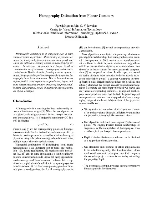
34Figure1.Theproduction-perfectioncycleofapart
1.IntroductionTheframeworkofthisworkisreverseengineering.Inpartsmanufacturing,reverseengineeringistypicallyconcernedwithmeasuringanexistingobjectsothatasurfaceorsolidmodelcanbededucedinordertotakeadvantageofCAD/CAMtechnologies.Itisalsooftennecessarytoproduceacopyofapartwhennooriginaldrawingsordocumentationareavailable.Inothercaseswemaywanttore-engineeranexistingpart,whenanalysisandmodificationsarerequiredtoconstructanewimprovedproduct.Eventhoughitispossibletoturntoacomputer-aideddesigntofashionanewpart,itisonlyaftertherealmodelismadeandevaluatedthatwecanseeiftheobjectfitstherealworld.Forthisreasondesignersrelyonreal3Dobjects(realscalewood,claymodels)asstartingpoint.Suchaprocedureisparticularlyimportanttoareasinvolvingaestheticdesigne.g.theautomobileindustryorgenerationofcustomfitstohumansurfacessuchashelmets,spacesuitsorprostheses.Forthesereasonsreverseengineeringisafundamentalstepofthenow-standardproduction-perfectioncycleofpart(Figure.1).ThisprocessstartswiththeCADstage.Next(step2),therapidprototypingstageconvertstheCADdataintoarealprototype.Rapidprototypingisatechniqueallowingthedirectproductionofprototypesbyacomputer-controlledprocess.Often,theshapeoftheproducedobjectundergoessomeimprovementcarriedoutbyhandtoadaptittoitsrealenvironment(step3).Thehand-improvedmodelis
revisedpaper.tex;6/04/2000;15:35;p.233D scanning CAD modelDesign with CAD
Optical measurementOptimization
Rapid prototyping
New constraints12
34Figure2.Manyhand-workedoptimization(step3)couldbereplacedbyestablishingnewconstraintsontheshapeandincorporatingtheminthemodeldesignprocess.
backagainintothedigitalworldofCADthrough3Dopticalmeasurementtechniques(step4),forinstancea3Dlaserscanner.Inthisprocessthenotionofconstraintsisnormallyinvolvedinstep1wheregeometricrelationshipsbetweenobjectfeaturestogetherwith3Dmeasurementdatacontributeintheproductionoftheoptimalobjectmodelshape.Thefirstmotivationbehindincorporatinggeometricconstraintsisthatmodelsneededbyindustryaregenerallydesignedwithintendedgeometricrelationshipsbetweentheobjectfeaturessothisaspectshouldbeexploitedratherthanignored.Theconsiderationoftheserelationshipsisactuallyneces-sarybecausesomeattributesoftheobjectwouldhavenosenseiftheobjectmodellingschemedidnottakeintoaccounttheseconstraints.Forexample,takethecasewhenwewanttoestimatethedistancebetweentwoparallelplanes:iftheplanefittingresultsgavetwoplaneswhicharenotparallel,thenthedistancemeasuredbetweenthemwouldhavenosignificance.Fur-thermoreexploitingtheavailableknownrelationshipswouldbeusefulforreducingtheeffectsofregistrationerrorsandmis-calibration,thusimprovingtheaccuracyoftheestimatedpartfeatures’parametersandconsequentlythequalityofthemodelling.Thesecondmotivationisthatoncethepartisproduced(step2)manyimprovementsarecarriedmanually(step3)tooptimizethepartandmakeitfitwiththerealworld(e.gfitwithanotherpart,adjusttheparttofitaparticu-