Preparation of monodispersed PNIPAm-silica composites and characterization
- 格式:pdf
- 大小:2.03 MB
- 文档页数:8
Standard Operating Procedure for Preparation of Aspergillus fumigatus Test Strains for Inhalational Pulmonary AspergillosisAnimal Studies1.PurposeThis Standard Operating Procedure (SOP) will provide information necessary for the uniform completion of Aspergillus fumigatus inoculumpreparations for use in infecting laboratory animals with experimentalpulmonary aspergillosis.2.ScopeThis SOP will provide sufficient information to allow preparation of a sufficient volume of concentrated Aspergillus fumigatus conidia (around 109to 1010 CFU/ml) for use in either the Madison or Acrylic inhalation chambers..3.Definitions.“Inoculum preparation” will mean to create a precise, quantified concentration of viable Aspergillus fumigatus conidia in a diluent suitable forsuspending and stabilizing the same.4.ResponsibilitiesThis SOP shall be utilized by employees of Research assistant status or higher without additional training. Research technicians may perform thiswork upon receipt of training.5.Equipment•Method A. (preferred)o Sterile phosphate buffered saline supplemented with 0.2% v/v Tween 80o RC5B High Speed Centrifuge (Sorvall)o Sorvall SS-34 rotoro Sterile Oakridge tubeso50 ml sterile polypropylene centrifuge tubes with flat top rim seal capso Parafilmo Sabouraud dextrose agar plateso Hemacytometer•Method B. (alternative)o Sterile normal saline supplement with 0.2% Tween 80o Beckman Model TJ-6 Table-top Centrifuge or equivalento Sterile disposable plastic inoculation loops (Fisher)o Potato dextrose agar plateso Parafilmo50 ml sterile polypropylene centrifuge tubes with flat top rim seal capso 5 ml sterile snap top polycarbonate tubeso Glass wool (2 x 2 piece) inserted into a 30 ml sterile glass syringe and sterilized as a unit ( 2)o Hemacytometero Amphyl (Revco) [Acceptable equivalent: Vesphene (Steris) or Decon (Decon Labs)]6.Procedure•Preparation of inoculumo Method A. (preferred)All manipulations should be performed at room temperature in a laminar flow hood or biological safety cabinet, with disposablehospital pads lining the work area unless otherwise indicated.Ten days before the planned day of infection inoculate 10 Sabouraud dextrose plates for each planned run (or acceptableequivalent medium) with 10 µl of test strain (i.e. Aspergillusfumigatus 293) conidial stock suspension pipetted to the center ofthe plate. Spread the inoculum all over the surface of the plate witha sterile loop. Seal inoculated SAB plates with parafilm, invertand grow at 37o C until the day of infection.Note: Seven days prior to the planned day of infection, inoculate an additional 5 Sabouraud dextrose plates with the test strain toensure contaminant-free plates of the test strain are available forharvesting conidia in the event the first 10 are contaminated orthere are problems with the growth of the strain.On the day of infection harvest conidia with PBS + 0.2% Tween80 (PBST) (or acceptable equivalent) by pipetting and aspiratingmultiple times across the surface of the plate. Use multiple washesof 8ml PBST per plate, repeatedly washing the culture surface untilconidia become suspended and the liquid is dark green. This takestime (approximately 8-10 min.) as the conidia tend to float on theplate. Avoid touching the culture with the pipette as this increasesthe yield of hyphal fragments. Use a total of 80 ml PBST toharvest from four well-conidiated plates.Collect the PBST plus conidia in two high speed Oakridge centrifuge tubes, and concentrate by high speed centrifugation (weuse 15,000 rpm [r avg 17,000 X g] for 10 minutes, at 4°C no brakein a Sorvall SS-34 rotor)After the spin, decant the supernatant from both tubes into a sterile 100ml flask, leaving approximately 5ml volume in one tube.Reserve the supernatant for re-spinning in case insufficientnumbers of conidia were isolated. Re-suspend the pellet in the 5mlvolume by vortexing.Pipet out the suspended conidia and add it to the second centrifuge tube containing only the conidial pellet and no supernatant. Rinsethe first tube with 5ml of the reserved supernatant, add to thesecond tube (total volume 10ml) and resuspend the second pellet.Vortex vigorously but do not sonicate. Count a 1:1000 or 1:10,000dilution in PBST with a hemacytometer for a target inoculum of 1-2 x 10⁹ conidia/ml.Confirm inoculum viability by serially diluting an aliquot of the inoculum in PBST. Prepare, three serial 1:100 dilutions of thestock, followed by plating 0.05 ml on Sabouraud dextrose agar intriplicate. This should yield approximately 50 colonies per platefor a target inoculum of 1-2 x 10⁹ conidia/ml. Incubate platessealed with parafilm at 37o C overnight and count the colonies thenext day.Conidial stock should be stored at 4°C until use.o Method B. (alternative):All manipulations should be performed at room temperature in a laminar flow hood or biological safety cabinet, with disposablehospital pads lining the work area unless otherwise indicated.Ten days before the planned day of infection inoculate 40 potato dextrose agar plates (PDA) per planned run with 10 µl of test strain(i.e. Aspergillus fumigatus 293) conidial stock suspension pipettedto the center of the plate. Seal inoculated PDA plates withparafilm, invert, and grow at 37o C until the day of infection.Note: Seven days prior to the planned day of infection, inoculate an additional 10 PDA plates with the test strain to ensurecontaminant-free plates of the test strain are available forharvesting conidia in the event the first 40 are contaminated orthere are problems with the growth of the strain.On the day of infection harvest conidia with sterile saline + 0.2% Tween 80 (NaCl-T) by pipetting 10 µl to the surface of a well-conidiated plate. Scrape the entire plate with a sterile disposableplastic loop ensuring that you only scrape the surface and not diginto the agar or scrape too vigorously as to spill buffer outside ofthe plate and reduce hyphal contamination.Aspirate the 10ml of NaCl-T + conidia from the plate and decant into a 50 ml conical tube. Add an additional 10 ml of NaCl-T ofwash to the surface of the plate and combine the washes in thesame conical tube.Repeat as necessary for the number of plates at hand. A total of 20-25 plates will normally be needed to yield 109 - 1010 CFU/ml perone run of either the Madison or the acrylic chamber.Collect and concentrate conidia in 50 ml conical tubes by centrifugation (in Beckman Model TJ-6 Table-top Centrifuge witha Beckman TH-4 swing bucket rotor) at 2500 rpm [r avg 1092 X g]for 10 minutes at room temperature.Discard supernatant into a large beaker (containing amphyl disinfectant) taking care not to disrupt pellet (the pellet will not bevery compact). Leave about 3 ml of supernatant in one tube andvortex to re-suspend pellet. Repeat with the second tube andcombine the re-suspended conidia with the contents of the initialtube. Wash tube 2 with 3ml of NaCl-T and add this to tube 1 anddiscard tube 2. Repeat with subsequent tubes until tube 1 reaches avolume of 40ml and start with a new tube. Repeat until thenumber of tubes are less than ½ the number of what you started.(You may also use a large sterile flask to collect all the conidia andwashes in one container at this time only).Place the autoclaved glass wool/syringe unit in a 50 ml conical tube. Pour the entire conidial solution through until the tube isfilled (approximately 40ml). Replace tube with a new one andrepeat. (This is done to filter out any hyphal fragments that may bepresent). If necessary, replace the glass wool/glass syringe unitwith another if the flow through begins to slow or is blocked.Concentrate conidia by centrifugation at conditions previously described and combine all pellets into one tube for one lastcentrifugation.Re-suspend the pellet in 30 ml of NaCl-T. Vortex vigorously.Make1:10,000 and 1:100,000 dilutions of the conidial stock in NaCl-T.Count the dilutions on a hemacytometer to determine CFU/mlAdjust the concentration of the stock with NaCl-T to yield 109 - 1010 CFU/ml, based on the needs of the specific inhalationalchamber being used. See preparation notes, below.Conidial stock should be stored at 4°C until use. [Conidial stock may be used up to 24 hours after it was initially prepared.However, conidia should be recounted prior to infection to re-confirm concentration.]Confirm inoculum numbers by plating 100µl the following dilutions: 106, 107 and 108 for an acrylic chamber run OR 107, 108and 109 for a Madison Chamber run on PDA plates overnight at37°C.•Preparation of final inoculum for particular chambers:o Acrylic chamber:Prepare a final inoculum consisting of at least 13 ml of 1 x 10⁹ conidia per ml in PBST (sterile saline + Tween 80). Note that eachrun will require 12 ml for infection for a single 1 hour run of thechamber.o Madison chamber:Prepare a final inoculum consisting of 20 ml of 1 x 10¹⁰ conidia per ml in PBST (sterile saline + Tween 80). Note that each runwill require approximately 12-15 ml for infection for a single 1hour run of the chamber7. AttachmentsN/A8. DeliverablesFor the purposes of this SOP, two similar deliverables are possible. First, for the Acrylic chamber, is the preparation of a final inoculum consisting of at least 13 ml of 1 x 10⁹ Aspergillus fumigatus conidia per ml in PBST or sterile saline + Tween 80. Each run will require 12 ml for infection for a single 1 hour run of the acrylic chamberThe second choice, specific to the Madison chamber will be a final inoculum consisting of 20 ml of 1 x 10¹⁰ conidia per ml in PBST or sterile saline + Tween 80. Each run will require approximately 12-15 ml for infection for a single 1 hour run of the Madison chamber9. ReferencesSheppard DC, Rieg G, Chiang LY, Filler SG, Edwards JE Jr, Ibrahim AS. Novel inhalational murine model of invasive pulmonary aspergillosis. Antimicrob Agents Chemother. 2004 May;48(5):1908-11.10. HistoryVersion 1.00.11. Examples of DeliverablesN/AD-7 Inoculate 2nd set of plates D0 Day of infection HarvestD+1 Overnight inoculum checkD -10Inoculate1st setof plates Strain Preparation Timeline(D = day)D-7 Inoculate 2nd set of plates D0 Day of infection Harvestconidida D+1 Overnight inoculumcheckD -10Inoculate 1st setof plates Strain Preparation Timeline(D = day)。
Magnetic nanobeads decorated by thermo-responsive PNIPAM shell as medical platforms for the efficient delivery of doxorubicin to tumour cells †Smriti R.Deka,‡a Alessandra Quarta,‡ab Riccardo Di Corato,b Andreas Riedinger,a Roberto Cingolani a and Teresa Pellegrino *abReceived 6th August 2010,Accepted 22nd September 2010DOI:10.1039/c0nr00570cMedical nanoplatforms based on clusters of superparamagnetic nanoparticles decorated witha PNIPAM thermo-responsive shell have been synthesized and used as drug carriers for doxorubicin (DOXO),a common chemotherapeutic agent.The nanosystem here developed has a total diameter below 200nm and exploits the temperature responsive behaviour of the PNIPAM polymeric shell for the controlled loading and release of DOXO.The system has been tested in vitro on tumour cells and it clearly demonstrates the effectiveness of drug polymer encapsulation and time-dependent cell death induced by the doxorubicin parative cellular studies of the DOXO loaded nanoplatform in the presence or absence of an external magnet (0.3T)showed the synergic effect of accumulation and enhanced toxicity of the system,when magnetically guided,resulting in the enhanced efficacy of the system.IntroductionIn the last decades,remarkable progress has been accomplished in the development of new polymer based functional materials,showing stimuli-responsive behavior.1–4These ‘‘smart’’polymers have found applications in different fields,including the phar-maceutical area.5,6In this field,the design of ‘‘intelligent’’drug delivery systems requires the preparation of carriers suitable for hosting,protecting,transporting the embedded drug and for controlling its release to the target site,under the action of a defined physical stimulus,such as the cellular pH,the local temperature,or the tumor reducing environment.On the other hand,the manipulation and the delivery of the nanocontainer and whatever it is associated to it,towards a selected area (a tumor or a damaged tissue)could be certainly enhanced and facilitated if superparamagnetic nanoparticles are included within the carrier systems.7The system becomes magnetically active upon the application of an external magnet as it will accumulate to the site where the magnet is applied,while it will be re-dispersed in solution upon the removal of the magnet.Additionally,magnetic nanoparticles,exposed to appropriate radio frequencies,could generate heat that can be exploited for hyperthermia treatment to kill tumor cells in cancer therapy or provide the external stimulus,the local heat,necessary to open the nanocontainer and release the drug.8–10It is then understandable while active research efforts are devoted to the combination of magnetic nanoparticles with stimuli-responsive polymers.Recently,we have reported on the exploitation of acidic pH-responsive nanogel as cargo for the controlled loading and release of pH-mediated iron oxide nanoparticles (IONPs)and at the same time of short oligonu-cleotides (which could be the therapeutic agents in some gene-therapy).11Different groups have been working on the growth of thermo-responsive polymers on the surface of IONPs.7,12–17Poly-(N -isopropylacrylamide),PNIPAM for instance is a linear polymer that experiences a conformational change from a random coil to a collapsed state at a critical temperature,also known as lower critical solution temperature (LCST),which is equal to 32 C.18,19In the case of the PNIPAM-shell on IONPs,it has been shown that the polymer transition from a coil to a shrinked state at the IONP surface promotes the inter-particle aggregation and consequently the aggregates reply faster to the magnet and can be easily separated.This behavior has been exploited to trigger the separation of individual magnetic nanoparticles from the solution phase,which is still difficult to be achieved.20,21Indeed,nanocrystals of iron oxide with dimension of the order of 10nm have a low magnetization per particle,and thus it is difficult to separate them from the solution or to control their movement in blood by using moderate magnetic fields.This limits their use in separation and drug delivery.Increasing the nanocrystal size increases the saturation magnetization,but also induces the superparamagnetic–ferromagnetic transition (at a domain size of ca.30nm for Fe 3O 4),so that nanocrystals are no longer dispersible in solution.22,23The PNIPAM shell on top of IONPs proposed here proved to trigger in a controlled manner the nanoparticles aggregation,thus maintaining the colloidal stability of superparamagnetic nanoparticles when the tempera-ture is kept below 32 C.20,24The above mentioned superparamagnetic nanoparticles coated with PNIPAM have been also exploited for the drugaIstituto Italiano di Tecnologia,via Morego 30,16163Genova,Italy.E-mail:teresa.pellegrino@unisalento.it;Fax:+390832298230;Tel:+390832298214bNational Nanotechnology Laboratory of CNR-NANO,via per Arnesano km 5,73100Lecce,Italy†Electronic supplementary information (ESI)available:A table summarizing the DOXO loading parameters,DLS of some steps of the reaction and additional TEM characterization images of the DOXO loaded nanobeads,and additional TEM characterization of cells treated with the nanobeads.See DOI:10.1039/c0nr00570c ‡These authors have contributed equally to this work.PAPER /nanoscale |NanoscaleP u b l i s h e d o n 16 N o v e m b e r 2010. D o w n l o a d e d o n 19/04/2014 11:57:59.View Article Online / Journal Homepage / Table of Contents for this issueencapsulation,25however,the temperature-mediated inter-particle aggregation might represent a problem for their exploi-tation as in vivo drug delivery carriers.Recently,secondary structures of magnetic nanocrystals obtained by controlled clustering of magnetic nanocrystals have been proposed as a valuable alternative to individual IONPs with potential as drug carriers.The clustering of magnetic nano-particles offers the advantage to increase the total magnetization of the system while retaining the superparamagnetic feature of the individual magnetic nanoparticles:the magnetic clusters can be easily dispersed in solution when the magnet is removed.However,their use as magnetic carriers for drug delivery requires a precise control of the size in order to obtain stable colloidal nanoclusters,(from now on referred to as nanobeads (NBs))which are at the same time small enough to avoid RES (reticu-loendothelial system)sequestration.26In this frame,we have recently reported a procedure to cluster,in a controlled manner,surfactant coated magnetic nanoparticles by enwrapping several iron oxide nanoparticles within a polymer shell of poly(maleic anhydride-alt -1-octadecene).27The proce-dure allows to precisely tune the size,the shape and the number of IONPs per bead and to modulate the magnetic response of the resulting nanobeads (NBs).In the present work,to engineer appropriate magnetically guided carriers we have first decorated the nanobead surface with an additional layer of a thermo-responsive polymer based on PNIPAM,then we have exploited this shell for the temperature-controlled loading and release of doxorubicin,a chemotherapeutic agent.The system was tested on tumour cells and these studies allow us to elucidate the main features of our magnetic temperature-responsive nanocarriers.In this work we demonstrate that the concept of magnetic cluster-like beads embedded in a PNIPAM shell has a great potential in the drug delivery of chemotherapeutics to tumour cells.Results and discussionPreparation of PNIPAM–NBs and their characterization The procedure for the synthesis of PNIPAM–NBs is illustrated in Scheme 1.By using a protocol recently reported by us,27we first prepared clusters of iron oxide nanoparticles,the so calledstarting NBs,by enwrapping multiple iron oxide nanoparticles (6nm in diameter)within an amphiphilic polymer named poly(maleic anhydride-alt -1-octadecene)(PC18).In order to grow the PNIPAM shell,the anhydride groups of the polymer at the bead surface could be further processed.For this purpose we first linked short priming ligands,the 2-aminoethylmethacrylate molecules (AEM)to the nanobead surface,the primary amino group of the AEM forms an amide bond with the anhydride group of the polymer.This step allows the introduction of C–C double bonds at the nanobead surface,which are the moieties that in the next step initiate the NIPAM copolymerization at the bead surface.More in detail,the addition of base (TEA)first deprotonated the AEM,which was subsequently added to the NBs in aceto-nitrile (ACN)under nitrogen atmosphere.After 24hours,the modified NBs were precipitated by addition of petroleum ether,and re-dispersed in acetone.The polymerization of NIPAM on the surface of NBs was carried out in water–acetone mixture.To the AEM–NBs in acetone,the radical initiator (AIBN in acetone)was first added,followed by addition of deionized water and NIPAM monomers and the mixture stirred for 6hours at 70 C under nitrogen atmosphere.At the end of the reaction the PNIPAM coated beads were at first magnetically separated and the excess of the NIPAM monomers was removed by few additional precipitation steps which allowed us to completely purify the PNIPAM–NBs from the NIPAM monomers left in the supernatant.As shown in Fig.1,while the starting NBs have an average diameter (determined by TEM)of 65Æ15nm,the final PNI-PAM–NBs have a corresponding diameter of 135Æ22nm,and the PNIPAM–NBs samples (as well as the starting NBs)are well dispersed on the TEM grid giving a clear indication of the growth of the PNIPAM shell around each individual starting bead.The change in size due to the polymer growth is also confirmed by the change in hydrodynamic diameter of the PNIPAM–NBs (286nm)with respect to the diameter of the starting NBs (146nm)in PBS as measured by DLS (Fig.S2†).(It is also worth to know that even for the intermediate product,the AEM-modified NBs,the TEM picture does not show any aggregation (data not shown)and the DLS diameter in acetone was of 189nm.)Scheme 1To grow the PNIPAM shell on magnetic nanobeads (NBs)starting from polymer coated NBs which expose at their surface anhydride groups,a two-step approach has been applied.In order to introduce C ]C double bonds groups at the NB surface,the NBs are first primed with 2-aminomethylmethacrylate and in a second step the NIPAM monomers are copolymerized by radical reaction at the bead surface.The structures are just cartoons which underline the functional groups at surface and do not correspond to the real molecular structures.P u b l i s h e d o n 16 N o v e m b e r 2010. D o w n l o a d e d o n 19/04/2014 11:57:59.The thermo-responsive properties of the nanobeads before and after the PNIPAM coating provide evidences of the modification of the bead surface.Fig.2displays the hydrodynamic diameter of the nanobeads when the temperature was increased from 20to 55 C (the heating curve)and vice versa when it was decreased from 55to 20 C (the cooling curve)for the starting NBs (Fig.2b)and for the PNIPAM–NBs in water (Fig.2a),respectively.The selected range of temperature allowed us to study the hydrodynamic size of the NBs above and below the LCST of the PNIPAM,which is,as reported for the linear PNIPAM polymer,around 32 C.As shown in Fig.2a,for the PNIPAM–NBs we found a well-defined volume change observed at a temperature around 32 C.The DLS diameter of the PNIPAM–NBs changes substantially from 286nm at 20 C to 250nm at 55 C,due to the transition from the random coil to the collapse state of the PNIPAM chains when the temperature was increased above32 C.The reversibility of the transition was also observed,as indeed the heating and the cooling curves were found to be basically equal.In the case of starting NBs in water,the hydro-dynamic diameter was almost constant at a diameter around 146nm over the temperature range from 21to 43 C and no transition occurs at 32 C (Fig.2b)while only a small variation of the DLS size of few nanometres was observed at temperature of 45 C,which might be due to a slight contraction of the polymer PC18of which the nanobeads are made occurring at this temperature.The same behavior was observed for the starting NBs in ACN,the solvent in which the nanobeads are prepared (in this case the mean diameter was averaged around 125nm,data not shown).The temperature responsive results observed on our PNI-PAM–NBs are in accordance with the findings of other groups that have grown the PNIPAM on other types of meso–micro templates (like silica beads or polymer beads).28–31It is important to point out that on meso-scale objects (100–200nm),like our PNIPAM–NBs,the polymer contraction involves a change of the volume at individual PNIPAM–NB and it does not involve inter-particle agglomeration.This behavior is obviously different from that of individual PNIPAM-coated IONPs in which the thermo-responsive behavior drives the inter-particle aggregation,leading to micrometre aggregates.The thermo-response behavior of our PNIPAM–NBs is definitely more advantageous when the system is designed for drug delivery as in vivo aggregation should always be avoided.The encapsulation of NBs within the PNIPAM shell has been additionally confirmed by the FT-IR fingerprint spectra obtained when comparing the starting NBs,the AEM–NBs and the PNIPAM–NBs respectively (Fig.3).In the IR spectrum oftheFig.1TEM characterization of the starting NBs (a and b)and corresponding PNIPAM–NBs (c and d)at low field and at high magnification.The statistical TEM-diameter measured (f)for the PNIPAM–NBs corresponds to 135Æ22nm and (e)for the starting NBs corresponds to 65Æ15nm.The statistics have been done on an average of 150beadsmeasured.Fig.2Temperature dependence of hydrodynamic diameter for (a)PNIPAM–NBs (blue diamonds:temperature increased from 20to 55C and violet squares:temperature decreased from 55to 20 C)and (b)starting NBs (black triangles:temperature increased from 20to 55 C and red diamonds:temperature decreased from 55to 20 C).P u b l i s h e d o n 16 N o v e m b e r 2010. D o w n l o a d e d o n 19/04/2014 11:57:59.starting NBs,the peaks at 1780cm À1and 1755cm À1could be assigned to the C ]O stretching (asymmetric and symmetric)of the carbonyl groups of the anhydride.After modification with AEM,the carbonyl peak of the carboxylate (per each AEM reacted towards to an anhydride group one carboxylate is produced)was slightly shifted to 1723cm À1.In addition,due to the formation of amide group,a small peak at 1645cm À1,likely due to the stretching of amide I carbonyl group (C ]O/N–H)and another at 1564cm À1,due to formation of amide II (N–H bend/C–H stretch)were observed.After NIPAM polymerization at the bead surface the peaks at 1645and 1564cm À1were shifted at 1652and 1544cm À1still due to the carbonyl of the amide groups of PNIPAM.Also,the signal of the amide carbonyl peak at 1652cm À1after PNIPAM polymerization was much stronger than the AEM-modified NBs,since the ratio of amide groups per bead increased.On the contrary,the peak at 1723cm À1of the carbonyl of the carboxylate was much weaker as it is screened by the PNIPAM polymer shell.Taken all together,the TEM data,the curves DLS diameter versus temperature and the FT-IR spectra provide clear evidence for the surface modification and the PNIPAM polymerization on the surface of the NBs.Loading of doxorubicin within PNIPAM–NBs and corresponding release experimentsThe thermo-responsive change in volume of the polymer shell can be exploited for both the loading and the release of drug molecules.At temperature of 20 C the PNIPAM–NBs have a larger DLS diameter as the PMIPAM shell is present in a random coil.We exploit the enhanced permeability of the PNIPAM shell at 20 C to load the doxorubicin (DOXO):the amount of DOXO loaded inside the PNIPAM–NBs has been determined by the difference between a solution of DOXO at initial concentration and that of DOXO left in solution after having magnetically separated the PNIPAM–NBs as sketched in Fig.4A and B (more details are available in the experimental parts).Thanks to the cumulative effect of several super-paramagnetic nanoparticles clustered per beads,the DOXO-loaded PNIPAM–NBs were easily accumulated to the magnet within 1hour,making the separation protocol much easier andfaster without the need of filtering or column purification protocols.In most of the loading experiments starting from a PNIPAM–NBs solution at Fe 50m g mL À1concentration,a DOXO solution of 67m g mL À1was added and in these conditions we could load within the PNIPAM shell a DOXO amount equal to 50.5Æ3.5m g mL À1(calculated on the average of 7independent experiments),which corresponds to a loading efficiency of about 75%(actually the highest loading efficiency we could reach).The release profiles have been recorded by using these loading conditions.However,by tuning the initial amount of PNIPAM–NBs and DOXO mixed together,we could vary the loading efficiency.For instance,we kept constant the initial amount of Fe at 12.5m g mL À1and by adding an initial amount of DOXO of respectively 10,16.8,or 100m g mL À1we could load within the PNIPAM–NBs respectively 6.5,12.5or 24m g mL À1,which correspond to a loading efficiency respectively of 65,74,and 25%.(Those sample have been tested later on the tumor cells,however,see Table S1†for the summary of the DOXO loading results obtained.)The loading of DOXO within the PNIPAM shell is also accompanied by an increase in the DLS diameters of the nanobeads from 286nm for the PNIPAM–NBs to 310nm for the DOXO-loaded PNIPAM–NBs,while no aggregations were shown on TEM image (Fig.S3†).The release profile of DOXO from the PNIPAM–NBs was studied at 37 C in a PBS buffer solution at pH 7.4as for all the subsequent cell studies the cell cultures were kept at this temperature.At temperature above the LCST,the PNIPAM shell becomes hydrophobic and leads to the collapse of the polymer layer and consequently allows the water soluble DOXO to diffuse out quickly from the polymer shell.We observed that after 6hours almost 45%of the loaded DOXO was released,which reached 50%release after 24hours and reached a percentage of DOXO release of 80%at least 72hours after keeping the system at 37 C.The maximum DOXO release percentage reached was around 85%after 110hours at 37 C.On the other hand,when keeping the DOXO-loaded PNIPAM–NBs sample at 4 C for about 72hours,only 4%of the DOXO encapsulated was released in solution.At 4 C,after 12and 24hours the amount of DOXO released wasnegligible.Fig.3(a)IR-spectra of starting NBs,AEM-modified NBs and PNIPAM–NBs.(b)Detailed IR-spectra of the region of interest for the PNIPAM growth for the AEM-modified beads and PNIPAM–NBs.P u b l i s h e d o n 16 N o v e m b e r 2010. D o w n l o a d e d o n 19/04/2014 11:57:59.Drug release experiments from DOXO-loaded PNIPAM–NBs on tumor cell lineageTo assess the drug delivery potential of the DOXO-loaded PNIPAM–NBs and the anticancer activity of the released DOXO,in vitro cytotoxicity assays were performed.Tumor KB cells were incubated with the DOXO-loaded carriers at different time courses (24,48and 72h)and at different concentrations of Fe/DOXO administered (1.25/1.25,2.5/2.5and 5/5m g mL À1)(Fig.5).The experiments were carried out both without (Fig.5a)and with (Fig.5b)the application of a small magnet (0.3T)placed beneath the cell plates and the toxicity behavior was measured by a cell viability MTT assay for respectively,starting NBs,empty PNIPAM–NBs and DOXO-loaded PNIPAM–NBs and was compared to that of free DOXO administered directly to the cell media.In the absence of a magnet (Fig.5a)it is evident that for the different time points tested and for most of the concentrations of the NBs employed,both the starting NBs and the PNIPAM–NBs showed cell mortality below 20%,which provides an indication for the low toxicity profile of the carriers themselves (actually in those cases,the cells after showing an acute toxicity at 24h,had the time to recover after 48and 72h).Those findings are in accordance with the data reported by Vihola et al.on bare PNIPAM polymer molecules tested on two different cell lines;a negligible toxicity of the PNIPAM polymer itself has been shown in their study.32More significant is the comparison of the toxicity observed at 24hours between the DOXO-loaded PNIPAM–NBs and that of free DOXO administered to the cells for the three concentrations tested.The encapsulation of the DOXO within the PNIPAM shell retards the toxic effect of DOXO on the cells as observed from the comparison of cell viability at the time point of 24hours(for instance for Fe/DOXO 1.25/1.25it corresponds to a cell survival of respectively 50%for the DOXO-loaded PNIPAM–NBs against the 25%of the free DOXO,and the trend is the same also for the other Fe/DOXO ratios).On the contrary,the long term toxicity,measured at the time points of 48and 72hours,for the DOXO-loaded PNIPAM–NBs tend to reach a cell viability value that is comparable with that of free DOXO,confirming the continuous time release of DOXO from the PNIPAM shell on longer time scale.It should be noticed that the DOXO release profile on the system itself,reported in Fig.4,well accounts for the trend observed on the cells,since the curve almost reached the release saturation when the sample was kept at 37 C for a period longer than 3days,while after 24h only 50%of DOXO was released.Importantly,the presence of a static magnet placed beneath the Petri dish should trigger the intracellular uptake of the beads due to the magnetic attraction of the magnetic NBs towards the magnet,thus favoring the amount of beads in contact with the cell membrane and consequently up-taken by the cells.27Indeed,this trend is confirmed by the experimental data (Fig.5b);the presence of the magnet induces an appreciable increase of the cytotoxicity compared to the corresponding samples incubated without magnet for all the Fe/DOXO concentrations tested.For instance,the viability of cells doped with DOXO-loaded PNI-PAM beads at Fe/DOXO concentration equal to 1.25m g mL À1after 24h is 40%when the incubation occurred with the magnet,while it corresponds to 50%without the magnet.One should be aware that in those experiments,it is not possible to discriminate the toxicity due to the DOXO release from extracellular nano-beads (even the DOXO released from non-internalized carriers in the cell medium could cross the cell membrane and entertheFig.4(A)Chemical structure of Doxorubicin and cartoon sketching the loading of DOXO:after mixing the PNIPAM–NBs with DOXO at 20 C for 12hours,the DOXO-loaded PNIPAM–NBs are magnetically separated from the free DOXO left in solution.(B)The amount of DOXO loaded is measured by the difference in PL between a solution of DOXO at the same concentration of that mixed with the PNIPAM–NBs and the DOXO left in solution after having magnetically removed the beads.Fluorescence spectra of free DOXO (olive)and DOXO left (pink)in solution after loading experiment.(C)DOXO release kinetics in PBS at 37 C for the DOXO loaded PNIPAM beads.P u b l i s h e d o n 16 N o v e m b e r 2010. D o w n l o a d e d o n 19/04/2014 11:57:59.nuclei,as well).Such effect,however,should occur in the same manner in both samples with and without the magnet (to discriminate such effect a different thermo-responsive polymer with a shrinking temperature over 37 C is required).The magnetic contribution to the cytotoxicity enhancement is more pronounced for short incubation times (at 24h),while after longer time,at 48and 72h,the DOXO release effect prevails more than the accumulation effect (an amount of DOXO enough to kill the tumor cells has been released even without the appli-cation of the magnet).To test the effect on the cell mortality when different amounts of DOXO have been encapsulated within the beads,KB cells were administered with PNIPAM–NBs (Fe 1.25m g mL À1,this nanobead concentration corresponds to the most negligible toxicity of the system itself)loaded with different amounts of DOXO,respectively 0.65,1.25and 2.5m g mL À1.(Fig.6).As expected,lower DOXO concentration corresponds to higher viability at 24h,although after 72h more than 80%cells were found dead.On the other hand,when the cells were incubated with 2.5m g mL À1DOXO,after 24h around 50%of cytotoxicity was recorded.These data also imply that a very low amount of drug (less than 1m g mL À1)is needed to exert a high cytotoxic effect,on a longer time scale of 72h.All these features could make this carrier system a powerful tool for in vivo chemotherapy against cancer,where it is fundamental that the drug is active not immediately,after the intra body injection,but only after thetumor site has been reached.33,34Also,lower drug amount needs to be administered to get complete tumor regression while minimizing the risk to develop chemoresistance.35–37Although it is not straightforward to compare our results with those obtained by other groups (as indeed different groups have used different ways to estimate the amount of iron oxide based nanostructures administered to the cells in their studies,25,38)it is remarkable to mention that in our experiments wedeliverFig.5In vitro cytotoxicity assay of PNIPAM–NBs loaded with DOXO performed (a)without and (b)with the application of an external magnet.KB cells were incubated for 24,48and 72h at 37 C with the loaded systems at different amounts of beads (1.25,2.5and 5m g mL À1of Fe)and DOXO (1.25,2.5and 5m g mL À1).The cytotoxicity of the starting beads,of the empty PNIPAM–NBs and of the free DOXO has been also tested and compared to that of DOXO-loadedPNIPAM–NBs.Fig.6Comparative cell viability assay of KB cells incubated with DOXO-loaded PNIPAM–NBs by keeping constant the amount of NBs (1.25m g mL À1Fe)and increasing the amount of DOXO loaded within the PNIPAM shell (respectively,0.65,1.25and 2.5m g mL À1).The cytotox-icity of the empty PNIPAM beads is also reported.For each sample the toxicity has been measured after an incubation time of respectively 24,48and 72hours,at 37 C.P u b l i s h e d o n 16 N o v e m b e r 2010. D o w n l o a d e d o n 19/04/2014 11:57:59.a DOXO concentration in the same range used by other groups,38–41however,by employing an amount of nanostructures (measured in terms of iron),lower with respect to that of other groups 41,42(to give an example the highest amount of iron of 5m g mL À1used in this work corresponds to an amount of iron oxide nanoparticles of 6nm in diameter of about 20nM).In order to correlate the toxicity data with the up-taking of the nanobeads,the intracellular amount of PNIPAM–NBs and starting NBs in terms of intracellular Fe amount was measured by means of elemental analysis (Fig.7and Table S2,ESI†).It is clear that either with or without the magnet the PNIPAM–NBs were internalized by the KB cells more efficiently than the starting NBs (Fig.7).Since the surface of both samples lacks any cellular addressing ligand or recognition molecule that could promote the interaction with the cell membrane and the inter-nalization,this behavior can be attributed to the different surface charge and structure displayed by the two samples:according to the z -potential measurements,PNIPAM–NBs are less negatively charged compared to the starting beads (À10mV and À40mV,respectively,in PBS)and indeed the reduced repulsion at the negative cell membranes facilitates the uptaking.43In the case of the PNIPAM–NBs some of the carboxyl moieties present at the starting NB surface are used in the reaction with the AEM priming molecules for the PNIPAM growth and thus do not contribute to the final negative surface charge of the carriers.Additionally,as also mentioned by others when PNIPAM–gold nanostructures have been studied,44the up-taking might be driven by the hydrophobic interactions between the cell membrane and the PNIPAM polymer.At 37 C,i.e.over the LCST,the PNIPAM polymer is in the collapsed and hydro-phobic conformation;indeed the interaction with the phospho-lipid part of the membrane could preferentially occur,thus enhancing the PNIPAM–NBs up-taking with respect to the starting NBs.In addition the higher cytotoxicity of the PNIPAM–NBs with respect to the starting NBs,is confirmed by the observation that the presence of the magnet considerably increases the internali-zation of the PNIPAM–NBs:after 72hours the intracellular Fe amount found was 2.5m g mL À1,equivalent to the amount ofPNIPAM–NBs externally administered to the cells.We conclude that the less negative surface provided by the PNIPAM shell to the beads,together with the magnetic manipulation of the inner core of the PNIPAM–NB system account for the efficient up-taking of the system developed in this work:after 72hours nearly 100%of the PNIPAM–NBs administered to the cells was taken up by the cells,when the magnet was placed beneath the cell dish (Fig.7).In Fig.7one should also notice that in general for all the samples the up-taking increases with time.This trend,however,is not maintained for the starting NBs after 72hours in the presence of the magnet.This behavior might be attributed to the reduced stability of the starting NBs that tend to aggregate and stick to the cell plate due to the magnetic attraction resulting in a lower number of beads present in solution.The cellular internalization of both starting NBs and PNIPAM–NBs was also visually monitored by TEM charac-terization of cells incubated with both starting NBs and PNI-PAM–NBs samples.Fig.8shows the intracellular localization of the starting beads after 24h incubation.Early and late endo-somes (Fig.8b)were present in the same cell:the early endo-somes were quite large,displayed an irregular shape and contained a considerable amount of beads.On the other hand,late endosome and endolysosomal compartments were evident even after 48h (Fig.S5†):single iron oxide nanoparticles were held inside the lysosomes suggesting that the pH conditions of the lysosomes could degrade the polymer layer.However,further studies on longer time scale need to be carried out in order to explain these findings.Even PNIPAM–NBs were phagocyted and retained into the endosomal compartments after 24h (Fig.9a).Fig.9b shows the last stage of the membrane invagination during the formation of an early endosome.Even from the structural morphology of the beads uptaken within the cells it is possible to recognize the PNIPAM–NBs as indeed in this case the polymer layer is much thicker with respect to the starting NBs.Also in this case,from a qualitative point of view,after 48h the cells were enriched with PNIPAM vesicles (Fig.S6†)and after 3days the cells appeared overflowing (Fig.S6†).Those TEM images,tough qualitatively,confirm the above reported trend of preferential up-taking by the cells of the PNIPAM–NBs with respect to the starting NBs (Fig.S6†).KB cells once incubated with DOXO-loaded PNIPAM–NBs (2.5/2.5m g mL À1Fe/DOXO concentration)were imaged at different time delays of 2,7and 15h incubation (Fig.10a–c).TheFig.7Intracellular amount of Fe content (m g mL À1)for cells treated with starting beads and PNIPAM coated beads at an extracellular concentration of 2.5m g mL À1.100000KB cells were incubated for 24,48and 72hours at 37 C with and without the application of an external magnet.After the incubation time the cells were digested and the Fe content was determined by elementalanalysis.Fig.8TEM images of KB cells incubated with the starting NBs (a)after 24h at 37 C.(b)Higher magnification of a portion of the same image showing an endosome containing a considerable amount of nanobeads,many nanostructures having an inner dark core corresponding to IONPs and a lighter polymer shell are well distinguishable within the endosome.P u b l i s h e d o n 16 N o v e m b e r 2010. D o w n l o a d e d o n 19/04/2014 11:57:59.。
专利名称:Process of preparation of peptides and n-carbamoyl protected peptides发明人:BOMMARIUS, ANDREAS,DRAUZ,KARLHEINZ,EICHHORN, UWE, DR.,JAKUBKE,HANS-DIETER, PROF.DR.,KOTTENHAHN,MATTHIAS申请号:EP01102668.9申请日:19960626公开号:EP1170301A1公开日:20020109专利内容由知识产权出版社提供摘要:Prepn. of peptides of formula NH2-CHR1-CONH-CHR2-COR3 (I) comprises treating an N-carbamoyl peptide of formula R4NHCO-NH-CHR1-CONH-CHR2-COR3 (III) with a carbamoylase, opt. in the presence of solvent; or by removing the carbamoyl protecting gp. chemically, opt. in the presence of solvent and/or acid. In the formulae, R1 and R2 = H; 1-6C alkyl (opt. interrupted or substd. by the heteroatoms N,O or S, where the heteroatoms are opt. substd. by H, 1-4C alkyl or benzyl or are opt. linked to carbon by double bonds); phenyl or benzyl (both opt. substd. by halo or OH); or heteroaralkyl (such as 3-indolylmethyl or 2-, 3- or 4-pyridylmethyl); R3 = 1-4C alkoxy, NH2, OH, NR1R2, benzoyloxy (opt. substd. by 1 of more of halo, NO2, NH2, 1-4C alkyl, or 1-4C alkoxy) or one or more units of type NH-CHR2-COR3; and R4 = H, 1-4C alkyl, phenyl (opt. substd. by 1 or more of halo, 1-4C alkyl, 1-4C alkoxy, NO2, CN, CF3, 1-6C alkoxycarbonyl, COOH or NR1R2), aralkyl (such as benzyl) (opt. substd. by halo, 1-4C alkyl or 1-4C alkoxy), naphthyl or heteroaralkyl (such as (sic) 2-, 3- or 4-thienyl or -pyridyl or 2-quinolyl).申请人:DEGUSSA-HUELS AKTIENGESELLSCHAFT 地址:60287 Frankfurt am Main DE国籍:DE更多信息请下载全文后查看。
收稿:2006年3月,收修改稿:2006年5月 3吉林省科技发展计划项目(N o.20173008)资助33通讯联系人 e 2mail :chuying @模板法合成核壳功能材料3张艳萍 褚 莹33(东北师范大学化学学院 长春130024)摘 要 模板法制备核壳功能材料是材料科学研究领域的一大热点,引起了广泛的关注。
本文结合本课题组在有机2无机核壳复合纳米粒子(空心球)领域的研究,较系统地评述了目前国内外利用模板法制备核壳粒子的研究进展,并概述了核壳纳米粒子(空心球)的发展前景和应用领域。
关键词 核壳材料 模板 空心球 纳米粒子中图分类号:O641;T B383 文献标识码:A 文章编号:10052281X (2007)0120035207The F abrication of Core 2Shell Functional Materials with Templates MethodZhang Yanping Chu Ying33(Faculty of Chemistry ,Northeast Normal University ,Changchun 130024,China )Abstract Fabrication of core 2shell functional materials is a hot research topic in materials science and attracts much attention in recent years.Based on our research w ork in organic 2inorganic core 2shell com plex nanoparticles (hollow spheres ),the development of fabrication of core 2shell particles with tem plate methods is reviewed.The development foreground and the application area of core 2shell nanoparticles are discussed.K ey w ords core 2shell materials ;tem plates ;hollow spheres ;nanoparticles1 引言核壳(core 2shell )材料一般由中心的核和包覆在外部的壳组成[1]。
Preparation of nano-magnesium phosphate gel andapplication in 3D bioprintingGood afternoon everyone! My name is Chen You, come from school of materials science and engeneering. Here, I will show you my end of term thesis contents.The title of my thesis is “Preparation of nano-magnesium phosphate gel for application in 3D bioprinting”. As we all know, 3D priting is an emerging research field and biopriting is also becoming increasingly important in the tissue engineering. So,what is the bioprinting. There are two pictures showed the process of bioprinting. It will be the possible method to replace traditional tissue engineering for manufacturing human tissue and organ in the future. But lacking of printable biomaterial has become the most obstacle in the development of 3D bioprinting. So we need to design a new biomaterial with good properties of injection, formability and biocompatibility. There- fore the main contents of my thesis is to introduce the preparation of nano-magnesium phosphate.This is the outline of my thesis. It contains three main parts. First is the present research situation about 3D bioprinting; Second is the preparation, characterization of nano-magnesium phospate(NMP). Third is the conclusions.My topic sentence is that the nano-manesium phosphate biomaterial has good properties of injection, formability and biocompatibility that can be used in 3D bioprinting. And there are six references.They are closely related to my thsis. I got them from some Web sites. At last, I show you many Web sites that can be used to search for academic literature. In my view, number 2 bai du scholar combine with number 4 google scholar is very useful method. We can obtain the most papers that we want to download.That’s all, thanks for your attention.。
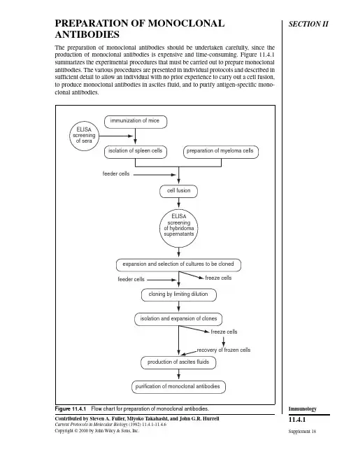
SECTION II PREPARATION OF MONOCLONAL ANTIBODIESThe preparation of monoclonal antibodies should be undertaken carefully, since the production of monoclonal antibodies is expensive and time-consuming. Figure 11.4.1summarizes the experimental procedures that must be carried out to prepare monoclonal antibodies. The various procedures are presented in individual protocols and described in sufficient detail to allow an individual with no prior experience to carry out a cell fusion,to produce monoclonal antibodies in ascites fluid, and to purify antigen-specific mono-clonal antibodies.isolation of spleen cells preparation of myeloma cellsfeeder cellscell fusionELISA screeningof hybridomasupernatantsexpansion and selection of cultures to be clonedfeeder cells freeze cellscloning by limiting dilutionisolation and expansion of clonesfreeze cellsrecovery of frozen cellsproduction of ascites fluidspurification of monoclonal antibodiesELISAscreeningof seraimmunization of miceFigure 11.4.1 Flow chart for preparation of monoclonal antibodies.Supplement 18Contributed by Steven A. Fuller, Miyoko Takahashi, and John G.R. HurrellCurrent Protocols in Molecular Biology (1992) 11.4.1-11.4.6Copyright © 2000 by John Wiley & Sons, Inc.11.4.1ImmunologyUNIT 11.4Immunization of Mice Antigen is prepared for injection either by emulsifying an antigen solution with Freunds adjuvant or by homogenizing a polyacrylamide gel slice containing the protein antigen.Mice are immunized at 2- to 3-week intervals. Test bleeds are collected 7 days after each booster immunization to monitor serum antibody levels. Mice are chosen for hybridoma fusions when a sufficient antibody titer is reached.BASICPROTOCOLPRODUCTION OF IMMUNE SPLEEN CELLS: IMMUNIZATION WITH SOLUBLE ANTIGEN Materials Phosphate-buffered saline (PBS; APPENDIX 2)Antigen Complete Freunds adjuvant Any strain mice, 6 to 8 weeks old Incomplete Freunds adjuvant 22-G needles 3-ml syringes with locking hubs (Luer-Lok, Becton Dickinson)Double-ended locking hub connector (Luer-Lok, Becton Dickinson)Sterile sharp scissors Sterile razor blades or scalpel blades Wooden applicator sticks 200-µl pipettor Additional reagents and equipment for ELISA (UNITS 11.2 & 11.3) and western blotting (optional; UNIT 10.8)1. Prepare an emulsion (200 to 400 µl/mouse) of equal volumes PBS containing 25 to 100 µg antigen and complete Freunds adjuvant. Using a 22-G needle, inject mice intraperitoneally. For each antigen, 3 to 5 mice are plete Freunds adjuvant contains mycobacteria—incomplete Freunds does not.An emulsion is most readily prepared by linking two locking syringes, one loaded with antigen and the other loaded with adjuvant, using a double-ended locking connector (see Fig. 11.4.2). Press syringe barrels back and forth, transferring contents from one syringe to the other , for 5 to 10 min until a stable emulsion is produced. For best antibody production, inject antigen in as small an emulsion volume as practicable.A stable emulsion is an oil-in-water emulsion which will not disperse when dropped into water . This is a useful check for the emulsification endpoint. Further , at the endpoint the emulsion will thicken noticeably.Mice may be restrained for immunization in the following manner: Place mouse on grilled cage top. Lift mouse by the tail (generally, when mice are lifted by the tail they will grab the bars of the cage top with their front feet, thus stabilizing themselves for restraint).Immobilize the mouse’s head by pinching together the skin at the base of the skull between thumb and forefinger . Turn hand over so that mouse is lying with its back against the palm.Wrap fourth finger around tail and stretch mouse over arched palm for intraperitoneal injection.CAUTION: Handle Freunds adjuvant carefully, since self-injection can cause a positive TB test and lead to a granulomatous reaction.2. Boost mice 3 weeks later by intraperitoneally injecting an emulsion (200 to 400 µl)of equal volumes PBS containing 10 to 50 µg antigen and incomplete Freunds adjuvant. The emulsion is prepared and injected as in step 1.Supplement 18Current Protocols in Molecular Biology11.4.2Immunization of Mice3-ml glass syringesdouble-endedLuer-Lok connectoror 3-way stopcockantigen and adjuvantFigure 11.4.2 Double-syringe device for preparation of antigen-adjuvant emulsions.3. Bleed mice 7 days after second immunization by cutting off 0.5 cm of the tail withsterile sharp scissors or a razor blade. Collect 100 to 200 µl blood into a 1.5-mlmicrocentrifuge tube. After clot formation, rim the clot with a wooden applicatorstick to dislodge the clot from the surface of the tube, but do not break up the clot.After clot retraction, transfer the serum into another microcentrifuge tube with a200-µl pipettor. If test bleeds are collected more than three times, it will be necessaryto cut the tail vein to obtain further samples rather than cutting off additional lengthsof the tail itself. This is done by nicking one of the lateral tail veins with a razor blade.The collection of blood may be facilitated by using a heat lamp to warm the mouse for 30sec to 1 min prior to cutting of the tail. Additionally, if blood flow from the cut tail is slow,the tail may be “milked” from base to the cut tip with thumb and forefinger.4. Determine the antibody titer in the serum by ELISA (UNITS 11.2 & 11.3). If desired,further characterize the antibody specificity by western blotting (UNIT 10.8).Antibody titer is operationally defined as that dilution of serum that results in 0.2absorbance units above background in the ELISA procedure.5. If the antibody titer is considered too low (≥1⁄1000) for cell fusion, mice can be boostedevery 2 weeks until an adequate response is achieved. Bleed the mice and test theserum with an ELISA.6. When the antibody titer is sufficient (>1⁄1000), boost mice by injecting 10 to 50 µgantigen in PBS intraperitoneally (200 to 400 µl), or intravenously (50 to 100 µl) viathe tail veins, 3 days before fusion but >2 weeks after previous immunization.In general, the higher the serum antibody titer, the more antigen-specific antibody-produc-ing hybridomas are obtained per fusion.If an antibody against a nonimmunodominant epitope is desired, the cell fusion may bedone at an earlier or later time, since the percentage of antibody-producing cells in thespleen directed at these less immunogenic regions of the antigen may vary with time in anunpredictable fashion.7. Perform cell fusion (UNIT 11.7) 3 days after the immunization (step 6).Immunology11.4.3 Current Protocols in Molecular Biology Supplement 18ALTERNATEPROTOCOLIMMUNIZATION WITH COMPLEX ANTIGENS (MEMBRANES, WHOLE CELLS, AND MICROORGANISMS)1. Prime the mice and boost intraperitoneally with adjuvant (i.e., complete Freunds for priming and incomplete Freunds for booster immunizations) as described for soluble antigen (see basic protocol, steps 1 and 2) or suspend antigen in PBS and inject. Use 1 to 2 × 10⁷ cells for mammalian species or 108 to 109 bacterial or yeast cells.2. Bleed the mice and determine the antibody titer of the serum as described for soluble antigen (see basic protocol, steps 3 to 6).3. Perform cell fusion (UNIT 11.7) 3 days after final immunization.ALTERNATEPROTOCOLIMMUNIZATION WITH ANTIGEN ISOLATED BY ELECTROPHORESIS In some instances the antigen under investigation can be purified most conveniently by gel electrophoresis (UNIT 10.2). Mice can be immunized with protein antigens still contained in a polyacrylamide gel slice, as described in this protocol.Additional Materials 0.1 M KCl, cold Tissue grinder Additional reagents and equipment for denaturing (SDS) discontinuous gel electrophoresis (UNIT 10.2)1. Apply a protein mixture containing 10 to 50 µg of the desired protein antigen to an appropriate denaturing (SDS) discontinuous gel electrophoresis system (e.g., the Laemmli gel system) and complete the electrophoresis as described in UNIT 10.2.2. Soak gel 5 to 15 min in cold 0.1 M KCl. Protein bands will appear as white precipitates against a clear gel background.3. Cut out the appropriate bands from the gel with a razor blade or scalpel blade.4. Prepare gel suspension by homogenizing the gel slice in a minimum volume of PBS using a tissue grinder. Minimum volume is defined by adding successive 100-µl volumes of PBS until the homogenized gel is liquid.Alternatively, the gel may be air dried for 1 to 2 hr , smashed with a glass rod, and suspended in a minimum volume of PBS.5. Immunize each mouse with 200 to 400 µl gel suspension containing 10 to 50 µg antigen via an intraperitoneal injection.Amount of antigen is estimated from prior observation of the proportion of desired protein antigen to other antigens in the sample as determined by the relative intensity of stained bands on the polyacrylamide gel (see UNIT 10.6 for staining procedures).6. Boost mice after 3 weeks with 200 to 400 µl gel suspension containing 10 to 25 µg antigen.7. Bleed the mice and determine the antibody titer of the serum as described for soluble antigen (see basic protocol).Mice immunized repeatedly with polyacrylamide tend to form adhesions that can make aseptic removal of the spleen difficult.8. Perform cell fusion (UNIT 11.7) 3 days after final immunization.Supplement 18Current Protocols in Molecular Biology11.4.4Immunization of MiceCOMMENTARYBackground InformationThe stimulation of an effective humoral im-mune response in mice is critical to the produc-tion of monoclonal antibodies directed at aparticular antigen. The variety and quality ofthe monoclonal antibodies prepared is gener-ally directly proportional to the serum antibodytiter in the particular mouse used for cell fusion.Any means of antigen preparation, antigen de-livery, or immunization schedule that increasesantibody titer in the serum of the immunizedmouse will potentiate the isolation of hybrido-mas secreting monoclonal antibodies of inter-est. We have described two methods of antigenpreparation: (1) antigen emulsified in Freundsadjuvants (probably the most common tech-nique used) and (2) antigen isolated in apolyacrylamide gel slice and homogenized.Other preparation methods (e.g., adsorption ofantigen to supports such as aluminum hydrox-ide or aluminum phosphate, polystyrene beads,or nitrocellulose paper, and alternate sites ofinjection such as footpads) are discussed in thekey references.Critical ParametersIt is desirable to use antigen of the highestavailable purity for immunizations, particu-larly for primary immunizations. Contami-nants may be more immunogenic than the an-tigen of interest and as such may result in a lowspecificity antibody. Mice given primary im-munizations of highly pure antigen may beboosted with less pure material (containing aslittle as one-third specific antigen in a complexprotein mixture).TroubleshootingPoor success in raising an adequate antibodytiter to an antigen of interest can be attributedto several factors. Improperly prepared emul-sion when using Freunds adjuvant (i.e., theaqueous and oil phases separate upon standing)is ineffective in stimulation of an immune re-sponse. Contaminants in an antigen preparationmay be more immunogenic, necessitating amore homogeneous preparation of the desiredantigen. Other parameters that can be varied inan effort to produce a higher antibody titer andincreased specificity include presentation ofantigen (Freunds adjuvant emulsion versuspolyacrylamide gel slice), site of immunization (intraperitoneal versus footpad or tail vein),antigen dose, and frequency of immunization.Alternate immunization protocols are pre-sented in the key references below.Anticipated Results Isolation of high-quality monoclonal anti-bodies correlates with high-serum antibody tit-ers. A serum ELISA titer of 1⁄1000 is the mini-mum level before attempting a cell fusion.Titers for most antigens (particularly from ani-mals injected with highly purified antigen) will range from 1⁄1000 to 1⁄100,000 after 3 to 4 immu-nizations. Occasional serum samples will titer at greater than 106. The proportion of mono-clonal antibodies of IgG class rather than IgM class generally increases proportionally to the duration of the immunization schedule, al-though this can vary dramatically among dif-ferent antigens. [In general, IgG class antibod-ies are more suitable for immunoassays, west-ern blotting (UNIT 10.8), immunoaffinity chromatography (UNIT 10.11), and immunopre-cipitation (UNIT 10.16)].Time Considerations A primary immunization followed by two booster immunizations and test bleeds will oc-cupy 6 weeks. For many antigens, however, an adequate antibody response in the mice is achieved only after several months and multiple immunizations.Key References Hurrell, J.G.R., ed. 1982. Monoclonal Hybridoma Antibodies: Techniques and Applications. CRC Press, Boca Raton, ngone, J.J. and V an Vunakis, H., eds. 1986. Im-munological techniques, Part I: Hybridoma tech-nology and monoclonal antibodies. Methods En-zymol. 121:1-947.Contributed by Steven A. Fuller and Miyoko Takahashi ADI Diagnostics Rexdale, Ontario John G.R. Hurrell Boehringer Mannheim Diagnostics Indianapolis, Indiana Current Protocols in Molecular Biology Supplement 1811.4.5ImmunologyUNIT 11.5Preparation of Myeloma Cells BASICPROTOCOLMyeloma cells are cultured with 8-azaguanine to ensure their sensitivity to the HA T selection medium (see UNIT 11.6) used after cell fusion (UNIT 11.7). One week prior to cell fusion, myeloma cells are grown in medium without 8-azaguanine. Cell culture conditions are adjusted such that the Sp2/0 cells are in the log phase of growth and exhibit high viability at the time of collection for fusion (UNIT 11.7).Materials Sp2/0 murine myeloma cell line (A TCC #CRL 1581)Complete culture medium 20 µg/ml 8-azaguanine Tissue culture flasks, 25 cm 2 or 75 cm 28% CO 2-in-air gas mixture Humidified 37°C, 8% CO 2 incubator Inverted microscope 1. Recover frozen cells from liquid N 2 storage, as described in UNIT 11.9.2. Grow Sp2/0 cells overnight in complete medium in tissue culture flasks at 37°C in a CO 2 incubator in 8% CO 2-in-air atmosphere with 98% relative humidity.3. Determine that the cells are growing by examining the cell cultures in the flasks with an inverted microscope and return culture flask to CO 2 incubator for continuation of cell growth.4. To ensure that the Sp2/0 cells remain aminopterin sensitive for the selection process following fusion, supplement the complete culture medium with 8-azaguanine at 20µg/ml during maintenance. One week prior to fusion, culture cells in medium without 8-azaguanine.A seeding cell density of 2.5 to 5 × 10⁴ cells/ml works well with Sp2/0 cells.Sp2/0 cells will grow to a maximum density of 6 to 9 × 10⁵ cells/ml, with a doubling time of 10 to 15 hr . When this density is reached, there is a rapid decline in cell viability. The Sp2/0 cultures are split every 2 to 3 days either by discarding an appropriate volume from the old flask and replacing with fresh medium or by transferring an appropriate volume of cells to a new flask and adding fresh medium. A 1-in-10 or 1-in-20 split is recommended.5. A total of 1 × 10⁷ Sp2/0 cells (i.e., 1:10 ratio to immune spleen cells) is used for fusion. Cell viability at the time of collection should be greater than 95%. To ensure that cells are collected in log phase of growth, adjust the cell density to 2 × 10⁵cells/ml the day before the fusion by adding fresh medium. Determine cell viability using the trypan blue exclusion method (see support protocol, below) on cells suspended in serum-free medium or PBS.SUPPORTPROTOCOLCELL VIABILITY TEST BY TRYPAN BLUE EXCLUSION This procedure is used to determine the number of viable cells present in the cell culture.A non-viable cell will have a blue cytoplasm; a viable cell will have a clear cytoplasm.Additional Materials Phosphate-buffered saline (PBS; APPENDIX 2) or serum-free complete culture medium 0.4% trypan blue solution Contributed by Steven A. Fuller, Miyoko Takahashi, and John G.R. Hurrell Current Protocols in Molecular Biology (1988) 11.5.1-11.5.3Copyright © 2000 by John Wiley & Sons, Inc.Supplement 1811.5.1Preparationof Myeloma CellsBinocular microscopeHemacytometer1. Centrifuge 1 ml cell suspension at 100 × g for 5 min.2. Resuspend the cell pellet in 1 ml PBS or serum-free complete culture medium.Serum proteins stain with trypan blue and can produce misleading results. Determinations must be made in serum-free solution.3. Mix 1 part of trypan blue solution and 1 part cell suspension (1⁄2 dilution).4. Using a binocular microscope, count the unstained (viable) and stained (dead) cells separately in a hemacytometer. Each of the four corner squares (composed them-selves of 16 smaller squares) have 1 mm sides and are 0.1 mm deep (0.1 mm 3). Count all cells within each of the four corner squares, including those that lie on the bottom and left-hand perimeters, but not those that lie on the top and right-hand perimeters.Count any clumps of cells as one cell. Calculate the mean number of cells per 0.1-mm 3volume. Multiply by 104 to obtain the number of cells/ml (i.e., cells/cm 3). Apply dilution factor for trypan blue (2×) to obtain the number of cells per milliliter of culture.5. Calculate the percentage of viable cells as follows:Viable cells (%) = Number of viable cellsTotal number of cells (dead and viable ) × 100REAGENTS AND SOLUTIONSComplete culture mediumDulbecco modified Eagle medium (DMEM), high-glucose formula (4.5 g glucose/liter; GIBCO/BRL #430-2100) supplemented to the indicated concentrations with the following additives:2.8 g/liter sodium bicarbonate (33.3 mM)4.8 g/liter HEPES (20 mM)10% fetal calf serum (v/v)10 ml/liter L -glutamine (2 mM)10 ml/liter sodium pyruvate (1 mM)10 ml/liter penicillin (50 IU/ml) and streptomycin (50 µg/ml)The last four additives are available as 100× solutions from GIBCO/BRL and other major suppliers of cell culture media. Penicillin and streptomycin are combined in one solution.Samples of fetal calf serum lots should be tested for ability to support efficient cell growth and cloning before a large purchase because there is much variability between lots of a given supplier. The fetal calf serum must be mycoplasma free. If low volume usage of fetal calf serum precludes testing of serum lots, purchase of mycoplasma-free, virus-free, low endotoxin sera from suppliers such as GIBCO/BRL, Flow Laboratories, or Sigma will generally provide satisfactory results. Horse or bovine serum is not an adequate substitute!Current Protocols in Molecular Biology Supplement 111.5.2ImmunologyCOMMENTARY Background Information The Sp2/0 cell line was chosen as the fusion partner for immune spleen cells because of its good rate of growth, the efficiency with which hybridomas are obtained after fusion, and, most importantly, because it does not synthesize or secrete any immunoglobulin heavy or light chains itself. The Sp2/0 myeloma cell line was developed by Schulman et al. (1978). Other commonly used cell lines are P3X63-Ag8.653(Kearney et al., 1979), which does not secrete immunoglobulins, and NS-1 (Kohler and Mil-stein, 1976), which produces only κ light chains.Critical Parameters Optimal growth of myeloma cells is density dependent. Cultures should be split at regular intervals to maintain >95% viability. Do not culture Sp2/0 cells longer than 1 month to avoid genetic drift and development of antibiotic-re-sistant contaminants. Maintain several aliquots of Sp2/0 cells in liquid nitrogen storage.Anticipated Results Proper care yields a healthy log phase myeloma cell culture able to sustain good pro-duction of hybridomas upon fusion.Time Considerations Depending on culture conditions, 105 cells can be expanded to the 107 cells required for fusion in 4 to 6 days.Literature Cited Kearney, J.F., Radbruch, A., Liesegang, B., and Ra-jewsky, K. 1979. A new mouse myeloma cell line that has lost immunoglobulin expression but per-mits the construction of antibody-secreting hy-brid cell lines. J. Immunol. 123:1548-1550.Kohler, G. and Milstein, C. 1976. Fusion between immunoglobulin-secreting and nonsecreting myeloma cell lines. Eur . J. Immunol. 6:511-519.Schulman, M., Wilde, C.D., and Kohler, G. 1978. A better cell line for making hybridomas secreting specific antibodies. Nature 276:269-270.Contributed by Steven A. Fuller, Miyoko Takahashi, and John G.R. Hurrell Allelix Inc.Mississauga, Ontario Supplement 1Current Protocols in Molecular Biology 11.5.3Preparationof Myeloma CellsUNIT 11.6Preparation of Mouse Feeder Cells for Fusion and CloningBASIC PROTOCOL Chilled sucrose solution is injected intraperitoneally into mice. When withdrawn, the solution contains feeder cells (macrophages and other cells) that are placed in the wells of microtiter plates 1 day prior to seeding of hybridomas from cell fusion (UNIT 11.7) or cloning (UNIT 11.8) procedures.Materials0.34 M sucrose solution, sterile and chilledMice (any strain)70% ethanolHA T medium, chilledSterile phosphate-buffered saline (PBS; APPENDIX 2)10-ml syringe, sterile18-G needle, sterile50-ml conical centrifuge tube, sterileDissecting boardForceps, sterileScissors, sterile96-well microtiter plates8% CO 2-in-air gas mixtureHumidified CO 2 incubatorAdditional reagents and equipment for estimating cell viability by trypan blue exclusion (support protocol, UNIT 11.5)1. Just prior to sacrificing a mouse, fill a 10-ml syringe with 8 ml chilled sucrose solution and attach 18-G needle.To avoid macrophages adhering to plastic surfaces, it is important to use chilled solutions to optimize cell harvest.2. Chill the 50-ml conical centrifuge tube in ice.3. Kill mouse by cervical dislocation.This is accomplished by firmly holding a thick pencil or similar rod-shaped object to the neck of the mouse just behind the skull and quickly and firmly pulling the tail.4. Immerse the mouse in a 100-ml beaker containing 70% ethanol.5. Lay out mouse on dissecting board.6. Snip skin at diaphragm level and pull skin back, exposing the lower part of the rib cage and abdomen.With forceps pull skin from underlying tissue at the diaphragm level and snip with a scissors. With forceps or sterile gloved hands, pull skin back at both sides of the incision to expose the lower part of the rib cage and abdomen.Care must be taken not to tear or cut the peritoneal membrane.7. Insert the needle into the peritoneal cavity at the base of the sternum and rest the tip of the needle over the liver. Inject sucrose solution. Gently squeeze the abdomen two or three times.8. Harvest the peritoneal feeder cells by withdrawing as much solution as possible into the syringe.Care must be taken not to puncture the digestive organs, which may lead to fecal contamination of the feeder cells.Supplement 1Contributed by Steven A. Fuller, Miyoko Takahashi, and John G.R. Hurrell Current Protocols in Molecular Biology (1988) 11.6.1-11.6.3Copyright © 2000 by John Wiley & Sons, Inc.11.6.1ImmunologyEnough peritoneal feeder cells can usually be isolated from one mouse to seed ∼100 to 300wells. However , some mice do not yield effective feeder cells. Depending on the total number of wells that must be seeded with mouse feeder cells, an appropriate number of mice must be killed. Peritoneal exudate feeder cells can be prepared up to 3 days prior to use.9. Transfer the feeder cell–containing sucrose solution into the 50-ml centrifuge tube.10. In a sterile fume hood, add 20 ml chilled HA T medium.11. Centrifuge at 100 × g for 5 min at room temperature.12. Resuspend the pellet in 1 ml chilled HA T medium and perform cell viability test by trypan blue exclusion as described in the support protocol, UNIT 11.5.13. Suspend the cell pellet in chilled HA T medium at 1 × 10⁵ cells/ml.14. Add 100 µl cell suspension to each of the 60 inner wells of the 96-well plates. The peripheral 36 wells are filled with sterile PBS.Plates having 24 wells may be used. If this is the case, add 1 ml cell suspension/well.15. Incubate plates overnight at 37°C in a CO 2 incubator in 8% CO 2-in-air with 98%relative humidity.REAGENTS AND SOLUTIONS The following solutions are sterilized by filtration through a 0.22-µm membrane. A suitable sterilization system is a disposable filter unit (e.g., Nalgene #120-0020). Glass-distilled water should be used for all preparations.0.34 M sucrose solution 58.2 g sucrose H 2O to 500 ml Filter sterilize and store at 4°C in 100-ml aliquots HAT (hypoxanthine/aminopterin/thymidine) medium Complete culture medium (see reagents and solutions, UNIT 11.5) supplemented to the indicated concentrations with the following additives: 20% (v/v) fetal calf serum 0.1 mM nonessential amino acids 100 µM hypoxanthine 0.4 µM aminopterin 16 µM thymidine These additives may be purchased in concentrated and sterile solutions from the major suppliers of cell culture media and reagents. Concentrated solutions of hypoxanthine and thymidine (HT) and aminopterin may also be prepared in the laboratory (see following recipes).100× HT solution Weigh 340.3 mg hypoxanthine and 96.9 mg thymidine; add water to 250 ml. Heat to 70°C to dissolve. Filter sterilize and store in 20-ml aliquots at −20°C. Thaw at 70°C for 10 to 15 min.1000× aminopterin solution Weigh 17.6 mg aminopterin. Add 60 ml water and dissolve by adding 0.1 M NaOH dropwise. Titrate with HCl to pH ∼8.5. Adjust volume to 100 ml and filter sterilize.Make 100× working solution by diluting stock in complete culture medium. Store in 5-ml aliquots at −20°C.Aminopterin precipitates at low pH and is light sensitive.Supplement 1Current Protocols in Molecular Biology 11.6.2Preparation of Mouse Feeder Cells for Fusion and CloningCOMMENTARYBackground InformationTo maximize the yield of hybrids from thefusion and cloning procedures, feeder cells arerequired to be cocultured with the hybrids,while hybrid cell density is low. Mouse perito-neal cells, most of which are macrophages,have been found to be convenient and effectivefeeder cells which are a source of solublegrowth factors for hybridoma cells.Critical ParametersFeeder cells such as peritoneal cells providebest support of hybridoma growth when used1 to 3 days after harvest. Use of chilledsolutions is necessary for optimum cell harvest,to prevent macrophages adhering to plastic sur-faces.Anticipated Results From 1 to 3 × 10⁶ peritoneal feeder cells are harvested from one mouse. The number of feeder cells will be enough to seed 100 to 300wells.Time Considerations Peritoneal feeder cells from one mouse can be processed in 1 hr or less.Contributed by Steven A. Fuller, Miyoko Takahashi, and John G.R. Hurrell Allelix Inc.Mississauga, Ontario Current Protocols in Molecular Biology Supplement 111.6.3ImmunologyUNIT 11.7Fusion of Myeloma Cells with Immune Spleen Cells BASICPROTOCOLFreshly harvested spleen cells and myeloma cells are copelleted by centrifugation and fused by addition of polyethylene glycol solution to the pellet. Cells are centrifuged again and the PEG solution diluted by slow addition of medium. Fused cells are centrifuged,resuspended in selection medium, and aliquoted into 96-well microtiter plates. Hybrido-mas are grown to 10 to 50% confluence and then assayed for production of antigen-spe-cific antibody.Materials Any strain immunized mouse (UNIT 11.3)Sp2/0 murine myeloma cells in active log phase (Am. Type Culture Collection #CRL 1581; UNIT 11.5)Diethyl ether 70% ethanol Dulbecco modified Eagle medium (DMEM) with supplements Sterile polyethylene glycol (PEG) solution HA T medium (UNIT 11.6)HT medium Phosphate-buffered saline (PBS; APPENDIX 2)15- and 50-ml centrifuge tubes Glass desiccator or metal can with lid Dissecting board 10.5-cm scissors (Irex #IR-105), sterile 10.5-cm forceps (Irex #IR-1393), sterile 60- and 100-mm petri dishes Stainless-steel strainer (Cellector; GIBCO #1985-8500), sterile 3-cc glass syringes with 26-G needle 5-ml serological pipets 37° C water bath Stopwatch 8% CO 2-in-air gas mixture Humidified CO 2 incubator Polyvinyl or polystyrene 96-well microtiter plates Inverted microscope Additional reagents and equipment for estimating cell viability by trypan blue exclusion (UNIT 11.5) and for detection of antibodies (UNIT 11.4)Preparation of myeloma and spleen cells 1. Just prior to sacrificing the mouse, transfer 1 × 10⁷ Sp2/0 murine myeloma cells (prepared as described in UNIT 11.5) to a 50-ml centrifuge tube. Check the percentage of viable cells using the trypan blue exclusion method (support protocol, UNIT 11.5).2. Sacrifice the mouse by anesthetizing with diethyl ether in a closed container (e.g., a glass desiccator or a metal can with a lid).At this point, a blood sample may be collected from the mouse by severing the blood vessels of one forelimb. Collect the blood with a Pasteur pipet and place the blood in a microcen-trifuge tube.3. Immerse the mouse in a beaker containing 70% ethanol and lay out on a dissecting board.Contributed by Steven A. Fuller, Miyoko Takahashi, and John G.R. Hurrell Current Protocols in Molecular Biology (1988) 11.7.1-11.7.4Copyright © 2000 by John Wiley & Sons, Inc.Supplement 111.7.1Fusion of Myeloma Cells with Immune Spleen Cells。
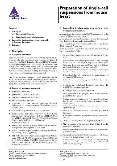
Contents1. Description1.1 Background information1.2 Reagent and instrument requirements2. Protocol for the dissociation of mouse heart withCollagenase II treatment3. References1. Description1.1 Background informationSingle-cell suspensions are a prerequisite for many experiments, for example to achieve the highest possible purity and recovery during cell separations with MACS® Technology. The gentleMACS™ Dissociator provides optimized programs to attain single-cell suspensions from various tissues, for example, mouse heart. In combination with C Tubes, the gentleMACS Dissociator allows the automated tissue dissociation in a closed system, enabling sterile sample handling. A single tube or two tubes can be processed in parallel.This protocol has been developed to obtain endothelial cells and Sca-1+cells from mouse heart using the gentleMACS Programs m_heart_01 and m_heart_02. Subsets of Sca-1+cells have been designated as progenitor/stem cells in mouse heart.¹,²1.2 Reagent and instrument requirements●gentleMACS Dissociator● gentleMACS C Tubes (# 130-093-237)●MACSmix™ Tube Rotator (# 130-090-753)●Cell strainer (70 µm mesh size)●(Optional) ART®1000 REACH™ pipet tips (MolecularBioProducts, Inc.) for removal of dissociated material from the closed C Tubes.● Red Blood Cell Lysis Solution (10×) (# 130-094-183)●Hanks’ Balanced Salt Solution with Ca²+and Mg²+(HBSS):1.26 mM CaCl₂, 0.49 mM MgCl₂•6H₂O, 0.41 mM MgSO₄•7H₂O,5.3 mM KCl, 0.44 mM KH₂PO₄, 4.17 mM NaHCO₃, 137.93 mMNaCl, 0.34 mM Na₂HPO₄, 5.55 mM Dextrose.Keep buffer cold (2−8 °C).●Collagenase II solution: Prepare a solution with 10,000 U/mLCollagenase II (Worthington, CLS-2) in HBSS.●DNase I solution: Prepare a solution containing 30,000 U/mLDNase I (e.g. DNase I, AppliChem).●PEB buffer: Prepare a solution containing phosphate-bufferedsaline (PBS), pH 7.2, 0.5% bovine serum albumin (BSA), and2 mM EDTA by diluting MACS BSA Stock Solution (# 130-091-376) 1:20 with autoMACS™ Rinsing Solution (# 130-091-222).Keep buffer cold (2−8 °C). 2. Protocol for the dissociation of mouse heart withCollagenase II treatment▲ For details on the use of the gentleMACS Dissociator, refer to the gentleMACS Dissociator user manual.▲ For cell culture experiments subsequent to tissue dissociation, all steps should be performed under sterile conditions.▲The weight of one mouse heart amounts to 80–115 mg (female BALB/c mouse, 6–7 weeks old).▲ One mouse heart or up to four mouse hearts (maximal 400 mg) can be processed per C Tube.1. Cut mouse heart transversely in two halfs and rinse with coldHBSS.2. Transfer mouse heart into the gentleMACS C Tube containing4.7 mL of HBSS. Add 300 µL Collagenase II solution (finalCollagenase II concentration: 600 U/mL) and 10 µL DNase I solution (final DNase I concentration: 60 U/mL).▲Note: This protocol has been optimized for the use of Collagenase II (Worthington, CLS-2). The use of other enzymes or enzyme concentrations is not recommended. 3. Tightly close C Tube and attach it upside down onto the sleeve ofthe gentleMACS Dissociator.▲Note: It has to be ensured that the sample material is located in the area of the rotor/stator.4. Switch on the gentleMACS Dissociator and choose thegentleMACS Program m_heart_01.5. Run the gentleMACS Program m_heart_01.6. After termination of the program, detach C Tube from thegentleMACS Dissociator.7. Incubate sample for 30 minutes at 37 °C using the MACSmixTube Rotator, or turn tube every 5 minutes to resuspend settled tissue fragments.▲Note:Operate MACSmix Tube Rotator on permanent run at a speed of approximately 12 rpm.8. Attach C Tube upside down onto the sleeve of the gentleMACSDissociator.▲Note:It has to be ensured that the sample material is located in the area of the rotor/stator.9. Choose and run the gentleMACS Program m_heart_02.10. After termination of the program, detach C Tube from thegentleMACS Dissociator.11. Perform a short centrifugation step to collect the sample materialat the tube bottom.12. Resuspend sample and apply the cell suspension to a cell strainer(70 µm mesh size) placed on a 50 mL tube.▲Note:Dissociated tissue can be removed from the closed C Tube by pipetting through the septum-sealed opening in the center of the cap of the C Tube. Use ART 1000 REACH 1000 μL pipette tips. Preparation of single-cell suspensions from mouse heart140-002-725.02Miltenyi Biotec GmbHFriedrich-Ebert-Straße 68, 51429 Bergisch Gladbach, Germany Phone +49 2204 8306-0, Fax +49 2204 85197macs@miltenyibiotec.de Miltenyi Biotec Inc.2303 Lindbergh Street, Auburn, CA 95602, USAPhone 800 FOR MACS, +1 530 888 8871, Fax +1 530 888 8925 macs@page 1/213. Wash the cell strainer with 5 mL of HBSS.14. Discard cell strainer and centrifuge cell suspension at 300×g for10 minutes. Aspirate supernatant completely.15. Resuspend cell pellet in 1 mL PEB buffer and add 10 mL 1× RedBlood Cell Lysis Solution.▲Note:For preparation of 1× Red Blood Cell Lysis Solution, refer to the data sheet of Red Blood Cell Lysis Solution (10×) (# 130-094-183).16. Incubate for maximal 2minutes at room temperature.17. Centrifuge at 300×g for 10 minutes. Aspirate supernatantcompletely.18. Resuspend cells in 1 mL PEB buffer and add to a final volume of10 mL.19. Centrifuge at 300×g for 10 minutes. Aspirate supernatantcompletely.20. Resuspend cells with PEB buffer to the required volume forfurther applications.3. References1. Oh, H. et al.(2003) Cardiac progenitor cells from adult myocardium: Homing,differentiation, and fusion after infarction. Proc. Natl. Acad. Sci. USA 100: 12313–12318.2. Pfister, O. et al. (2005) CD31– but Not CD31+ Cardiac Side Population Cells ExhibitFunctional Cardiomyogenic Differentiation. Circ. Res. 97: 52–61.All gentleMACS Protocols are available at . WarrantyThe products sold hereunder are warranted only to be free from defects in workmanship and material at the time of delivery to the customer. Miltenyi Biotec GmbH makes no warranty or representation, either expressed or implied, with respect to the fitness of a product for a particular purpose. There are no warranties, expressed or implied, which extend beyond the technical specifications of the products. Miltenyi Biotec GmbH’s liability is limited to either replacement of the products or refund of the purchase price. Miltenyi Biotec GmbH is not liable for any property damage, personal injury or economic loss caused by the product.MACS is a registered trademark and autoMACS, gentleMACS, and MACSmix are trademarks of Miltenyi Biotec GmbH.ART is a registered trademark and REACH is a trademark of Molecular BioProducts, Inc..Copyright © 2010 Miltenyi Biotec GmbH. All rights reserved.140-002-725.02Unless otherwise specifically indicated, Miltenyi Biotecproducts and services are for research use only and not fordiagnostic or therapeutic use.page 2/2。

专利名称:Preparation of polyphenylene ethers, and an apparatus for this purpose发明人:Hermann Brandt,Hermann Fischer,Hermann Dreher,Eduard Heil,JuergenHambrecht,Herbert Naarmann,AdolfEchte,Hermann Gausepohl,PeterSiebel,Johann Swoboda,GerdSchwoebel,Albert Nikles申请号:US06/797884申请日:19851114公开号:US04696996A公开日:19870929专利内容由知识产权出版社提供摘要:Polyphenylene ethers are prepared from monohydric phenols, which possess alkyl substituents in the two ortho-positions and, if desired, in the meta-position, but not in the para-position, by an oxidative coupling reaction with oxygen at from 15° to 50° C. and under from 1 to 10 bar in the presence of a catalyst complex, of a solvent and, if required, of an activator, by a method in which the conversion of the phenols is carried out in two more reaction zones, in which some or all of the solvent, the catalyst complex and the phenols and, where relevant, the activator is initially taken and is circulated by means of a conveying unit, and about 60-100% of the stoichiometric amount of oxygen required for the oxidative coupling is introduced into the first reaction zone and from 0 to about 40% of the said stoichiometric amount is introduced into the second reaction zone.申请人:BASF AKTIENGESELLSCHAFT 代理机构:Keil & Weinkauf更多信息请下载全文后查看。

专利名称:PREPARATION OF 5-MONOARYL-3-ASTRIAZINONES SUBSTITUTED AT THE 2-POSITION发明人:GUY PITET,HENRI COUSSE,ANTOINESTENGER,MICHEL BRILEY,PHILIPPE CHOPIN 申请号:AU6759587申请日:19870115公开号:AU597327B2公开日:19900531专利内容由知识产权出版社提供摘要:The present invention concerns new 5-monoaryl as.-triazin-3-ones substituted in 2-position, a method of preparing them, and their use as medicaments. The compounds according to the present invention have general formula (I) (I) in which: the bond represented by a dashed line indicates the presence of an optional double bond; A represents a direct N-C bond, a straight or branched C1 to C5 alkylene, possibly substituted one or more times by -COOR' or by Ar; R represents -H, -OH, +TR R' represents -H, -OH, straight or branched C1 to C7 alkyl, -NH2; Ar represents an aromatic ring having 5 or 6 members possibly containing a heteroatom such as O, N, S and possibly substituted one or more times by a radical selected from among -OH, C1 to C4 alkyl, C1 and C4 alkoxy, halogen, -CF3, acetonyloxy, and gamma -butyrolactone; as well as their pharmaceutically acceptable salts.申请人:PIERRE FABRE MEDICAMENT更多信息请下载全文后查看。
Preparation of monodispersed PNIPAm/silica composites and characterization of their thermal behaviorsYong-Geun Lee,Chang-Yong Park,Kyung-Ho Song,Sung-Soo Kim,Seong-Geun Oh*Department of Chemical Engineering,Hanyang University,17Haengdang-dong,Seongdong-gu,Seoul133-791,Republic of Korea1.IntroductionThe creation of new hybrid materials has focused on thepreparation of significant organic–inorganic materials[1,2],because they exhibit good mechanical properties and biocompati-bility simultaneously.The functional hybrid materials have founddiverse applications in diagnostic,coating,and catalyst because oftheir novel and excellent properties such as mechanical,chemical,electrical,rheological,magnetic and catalytic,by varying theircomposition,dimension,and structure of the materials[3–8].Notably,silica[9–11]is a useful material as a substrate ofhybrid materials which can be controlled easily depending on thevarious synthetic factors such as temperature,pH,and concentra-tion of reactants.Also,silica materials offer many advantages to thehybrid materials.When the hybrid materials were made using asilica sources,they show a better mechanical strength withimproved chemical and thermal stability together.Moreover,theydo not swell in most solvents,which prevent the degradation ofentrapped bimolecular components.To modify the hybrid materials which can be applied for DDS(Drug Delivery System),many strategies have been tried to releasethe encapsulated drug sources effectively.However,the drivingforces for release of the encapsulated species are limited to osmoticpressure,rupture of outer shell and diffusion.These limitationshighlight the need for fabrication of hybrid particles with newproperties,which can respond to the changes of temperature,pH,electricfield or light intensity.In recent years,poly(N-isopropylacrylamide)(PNIPAm)is oneof the most commonly studied stimuli-responsive polymers.Generally,poly(N-isopropylacrylamide)-based microspheres andmicelles have been synthesized via emulsion polymerization[12],inverse suspension polymerization[13],and self-assembly ofpoly(ethylene oxide)-b-(N,N-dimethylacrylamide-s-N-acryloxy-succinimide)-b NIPAm block polymers[14].In particular,thispolymer has both lower critical solution temperature(LCST)andupper critical solution temperature(UCST)interestingly.The linearpolymer of PNIPAm provides a nonionic water soluble propertywith a lower critical solution temperature(LCST)of$328C[15].Itswells below318C and shrinks above328C in aqueous solution,which means that PNIPAm releases most of its water content above328C.Due to their well-known temperature-responsive propertywith a LCST of around328C,PNIPAm can be easily applied in thearea of bio-medical science.The silica/polymer hybrid/composite particles with variousinteresting morphologies,such as silica core/organic shell[16],organic core/silica shell[17],raspberry-like[18],snowman-like[19],daisy-shaped and multipod-like[20],and raisin bun-like[21]have been afforded by different techniques.In this study,we report a facile and successful synthesis ofPNIPAm/silica core–shell hybrid spheres for thefirst time.Firsttype of hybrid materials is a PNIPAm polymer grafted silica hybridparticles(silica is a core material and PNIPAm polymer is a shellmaterial).In our previous work,VTMS silica spheres as a substratewere prepared using a remodeled sol–gel reaction[22].BecauseJournal of Industrial and Engineering Chemistry18(2012)744–751A R T I C L E I N F OArticle history:Received15June2011Accepted23July2011Available online12November2011Keywords:Hybrid materialsSilicaPNIPAmVinyl trimethoxysilanePhase transition temperatureA B S T R A C TTwo types of thermosensitive poly(N-isopropylacrylamide)(PNIPAm)-silica organic/inorganic hybridparticles were successfully prepared in aqueous solution through a facile synthetic process.Silanecoupler of vinyl organic groups connects the PNIPAm to silica.First,hybrid spheres were prepared bygrafting PNIPAm polymers to VTMS(vinyl trimethoxysilane)silica spheres.The thickness of polymershell on the silica surfaces could be easily controlled by varying the concentrations of NIPAm monomer.Second,another type of hybrid particle was fabricated by encapsulating PNIPAm polymer with silicamaterials.The PNIPAm polymers were completely encapsulated by silica shell.The morphologies andshell thickness were characterized through SEM and TEM.The variations of phase transition temperatureof PNIPAm were measured using DSC.ß2011The Korean Society of Industrial and Engineering Chemistry.Published by Elsevier B.V.All rightsreserved.*Corresponding author.Tel.:+82222200485;fax:+82222944568.E-mail address:seongoh@hanyang.ac.kr(S.-G.Oh).Contents lists available at SciVerse ScienceDirectJournal of Industrial and Engineering Chemistryj ou r n al h o m e p a g e:w w w.e l se v i e r.co m/l oc a t e/j i e c1226-086X/$–see front matterß2011The Korean Society of Industrial and Engineering Chemistry.Published by Elsevier B.V.All rights reserved.doi:10.1016/j.jiec.2011.11.117the VTMS silica particles have a large amount of vinyl groups on the surfaces,PNIPAm polymer can be effectively attached to the silica substrate through the copolymerization.Also,shell thickness could be controlled by changing the concentration of polymer.Second type is a silica coated PNIPAm hybrid nano particles (PNIPAm polymer is a core material and silica is a shell material).Using an as-prepared NIPAm–VTMS oligomer,PNIPAm polymer can be easily entrapped into the silica spheres.The characteristics of hybrid silica particles were investigated by SEM,TEM,TGA,FT-IR,DSC and NMR measurements.2.Experimental2.1.MaterialsVinyl trimethoxysilane as a silica source,N,N-methylenebi-sacrylamide (MBA)as a crosslinker of polymerization,and potassium peroxydisulfate (KPS)as an initiator of polymerization were purchased from Sigma–Aldrich Chemical Company.Ammo-nium hydroxide (NH 4OH,25%)as a catalyst for the formation of silica was given from Wako Pure Chemical Industries.N-isopropylacrylamide (NIPAM)as a monomer of PNIPAm was obtained from Acros Organics.Acetone,ethanol,and methanol were purchased from Duksan Pure Chemical Company.All chemicals were used as received without further purification.Water was obtained from Milli-Q water purification system (Millipore).2.2.Preparation of vinyl-functionalized silica (VTMS silica)particlesThe 10g of VTMS was added into 100g of water with stirring until the oil (VTMS)droplets have completely disappeared and a transparent solution was obtained.NH 4OH (0.1mL)was added to the mixture solution,and then the reaction was progressed during 12h at room temperature.After completion of the reaction,the resulting precipitates (VTMS silica)were centrifuged and washed several times using alcohol.2.3.Preparation of PNIPAm coated hybrid silica particlesPolymer/inorganic hybrid silica particles were synthesized by radical copolymerization of VTMS silica with NIPAm monomers.The 0.015g of KPS was added into the 10g of water,and then the 1.35g of ethanol solution including 0.15g of VTMS silica particles was added into the KPS solution.Next,this solution was added into the 10g of water solution containing 0.05g of MBA and NIPAm monomer with stirring.With increasing the concentration of NIPAm monomer to 0.15g,0.3g,0.45g,and 0.6g,formation of particles was examined.The solution heated at 708C for 12h and the PNIPAm coated hybrid silica particle can be obtained.The particles were centrifuged at 3000rpm for 15min and washed several times with methanol to remove the remainders.The powders were dried in a vacuum oven at room temperature for 24h.2.4.Preparation of hybrid silica particles encapsulating PNIPAm polymerThe 0.4g of NIPAm monomer,0.03g of MBA,and 0.5mL of VTMS were added into the 20g of water with vigorous stirring.After 30min of mixing,the 10g of water solution including 0.01g of KPS was added into the NIPAm solution.Next,the solution was heated to 808C to synthesize the PNIPAm core particle.After 12h of reaction,the 0.25g of VTMS and 0.3mL of NH 4OH were added to prepare the shell structure comprised of silica materials.The reaction was carried out for 12h at room temperature.The resulting precipitate was centrifuged and washed several times with ethanol.2.5.CharacterizationsField emission scanning electron microscopy (FE-SEM,JEOL Co.Model JSA 840A and JSM-6700)was used to observetheFig.1.SEM images of silica spheres prepared using VTMS organosilane at differentmagnifications.Fig.2.Schematic representation of the formation of PNIPAm polymer/silica hybrid particles.Y.-G.Lee et al./Journal of Industrial and Engineering Chemistry 18(2012)744–751745morphology of the particles.Before the FE-SEM investigation,samples were coated with platinum by sputtering for 3min.The transmission electron microscopy (TEM)pictures were taken through JEOL JEM-2000EXII microscope operating at 200kV.The samples of TEM are obtained by dispersing a small dropping of the suspension with lower concentration onto a copper grid pre-coated with amorphous carbon.And then,the TEM grid was dried in drying oven at 408C for 1day.For TGA measurements,samples were tested with a TGA7(PerkinElmer)Thermogravimetric Analyzer.All tests were performed under atmospheric pressure.The heating rate was 28C min À1from 25to 7008C.The LSCT of poly-(NIPAM)grafted hollow silica particles were characterized by Differential Scanning Calorimetry (DSC2010,TA instrument)between 10and 508C at the rate of 28C min À1under nitrogen atmosphere.3.Results and discussion3.1.Preparation of PNIPAm polymer grafted silica hybrid particlesSEM images (Fig.1)show the VTMS silica particles prepared by the simple one-step reaction in aqueous solution.VTMS silica is composed of many vinyl groups and showed uniform spherical shape with average diameter of about 1m ing a VTMS silica particles as a substrate,it was possible to prepare the highly monodispersed PNIPAm/silica particles consisting of core–shell hybrid structure (Fig.2).The thickness of PNIPAm polymer on the surface of silica particles at different weight ratios (NV,NIPAm monomer/VTMS silica)are shown in Fig.3.In the case of VTMS silica particles,they have a large amount of vinyl organic groups on their surfaces.So,after polymerization of NIPAm monomer,PNIPAm polymer canbeFig.3.Typical TEM images of hybrid PNIPAm/silica particles with varied PNIPAm shell thickness at different weight ratios (NV,NIPAm monomer/VTMS silica):(A)NV =1,(B)NV =2,(C)NV =3,and (D)NV =4.Fig. 4.Relationship between the thickness of PNIPAm polymer and the concentration of NIPAm monomer.Y.-G.Lee et al./Journal of Industrial and Engineering Chemistry 18(2012)744–751746easily attached to the silica surface.The inset TEM picture confirms that the particles are spherical shape.When the NV is 1,the thickness of PNIPAm is small and approximately 6nm.In contrast to the TEM images shown in Fig.3A,Fig.3B–D shows the core–shell structure clearly.When the amount of NV increases to 2,a thicker shell of PNIPAm is formed about 10.5nm on the silica surfaces.Interestingly,with the further increase of NV to 3and 4,the thickness of polymer increases to approximately 13.7nm and 17.9nm and the core–shell structure become more regular and distinguishable.As a result,it can be found that thethickness of PNIPAm polymer increases with the increases of an amount of NIPAm monomer.Also,low NIPAm concentration cannot lead to the successful formation of PNIPAm/silica hybrid particles.Fig.4summarizes the relationship between the thickness of polymer shells and various concentrations of NIPAm monomer.The amount of PNIPAm polymer grafted onto the silica surfaces was investigated by TGA curves as shown in Fig.5.An overall weight loss of $5%was attributed to the evaporation of physisorbed and chemisorbed water.The majorthermalFig.6.FT-IR spectra provide evidence of the PNIPAm/silica hybrid particles.(A)VTMS silica particles and (B)PNIPAm/silica hybridparticles.Fig.7.DSC thermograms of samples:(A)NV =1,(B)NV =2,(C)NV =3,and (D)NV =4.Fig.5.TGA curve of samples:(A)VTMS particles,(B)NV =1,(C)NV =2,(D)NV =3,and (E)NV =4.The initial weight loss is due to the evaporation of residual water,while the two-step weight loss is due to the degradation of PNIPAm.When the NV is 4,the highest weight loss was revealed.Y.-G.Lee et al./Journal of Industrial and Engineering Chemistry 18(2012)744–751747degradation of material is appeared at 300–5008C,which supports that the most polymers were removed.There is a minor weight loss between 500and 7008C,which can be attributed to the release of gases formed during the decomposition process.Especially,the weight loss rates of the hybrid particles were increased as the values of NV increased.When the NV values are 1and 2,weight loss of polymer was revealed around 18%and 25%,respectively.Moreover,when the NV is 3,overall polymer weight lose is showed as about 40%.The highest concentration of NIPAm monomer (NV is 4)led to noticeable weight loss to 60%due to the large amount of polymer degradation grafted onto the silica surface.SiO 2could not be decomposed in the experimental temperature range.It is clear from the TGA data that the amount of NIPAm monomer leads to the growth of the shell thickness on the particle surface.To identify the presence of molecular structure of as-synthe-sized VTMS silica spheres,FT-IR measurement was conducted [23].Fig.6A shows the FT-IR spectra of VTMS-silica bare particle.The asymmetric stretching vibrations of the siloxane (Si–O–Si)appear between 1200and 1000cm À1,and the symmetric stretching vibrations of the siloxane (Si–O–Si)appear at 800cm À1in the spectra of all the samples.The band at 3700–3200cm À1,which is attributed to the stretching vibration of Si–OH in silanol group,is also the typical band of silica,and the broad peaks at $3350and 1620cm À1indicated that silica contains the large amounts of adsorbed water in atmospheric moisture.Obvious peak at 1600cm À1is due to the presence of C 55C group in VTMS.However,in contrast to the IR data of VTMS silica particles,PNIPAmgraftedFig.8.The scheme for the formation of hybrid silica particles encapsulating PNIPAmpolymer.Fig.9.SEM (A)and TEM (B)images of hybrid spheres fabricated by NIPAm–VTMSprecursor.Fig.10.TEM image of hollow silica shell after removal of PNIPAm core.Y.-G.Lee et al./Journal of Industrial and Engineering Chemistry 18(2012)744–751748silica reveals the different peaks.In the spectrum of PNIPAm grafted hybrid silica particles(Fig.6B),a new absorption band of C55O at1700cmÀ1is observed.These results confirm that PNIPAm are grafted onto the surface of VTMS silica particles.DSC was used to study physical properties of the hybrid materials as shown in Fig.7.An endothermic point could be seen owing to the phase transition of PNIPAm,and the maximum endothermic peaks of the sample around348C are defined as the phase transition temperature(LCST)[24].When the NV values were1and2,the endothermic peaks were not clearly detected due to the small amount of PNIPAm in hybrid particles.In contrast to the LCST of pure PNIPAm(328C),the LCST of PNIPAm grafted silica particles was increased to33.5and348C when NV values were3 and4.In the current results,it is confirmed that the surfaces of silica particles are successfully grafted by PNIPAm polymer.3.2.Preparation of hybrid silica particles encapsulating PNIPAm polymerTo prepare the hybrid particles,first of all,it is important to synthesize precursor.NIPAm–VTMS complex monomers were synthesized by the reaction of NIPAm with VTMS in the presence of KPS and MBA as shown in Fig.8.The reaction took place between a vinyl group of NIPAm and VTMS as a co-polymerization.Fig.9shows the typical SEM and TEM images of the hybrid spheres prepared with PNIPAm as a core material and silica as a shell material at408C.The diameters of the hybrid spheres are shown in Fig.9A and B to a range of250nm mean diameter.To confirm the core–shell structure of hybrid materials,the particles were calcined at6008C for5h.Through the calcination step,PNIPAm polymer of the hybrid particle can be effectively decomposed and eventually removed.However,inorganic materi-als are not affected by the high temperature and the silica materials are remained as the hollow structure.Their TEM images show the lighter center portion and the darker edge,which further confirms their hollow structure(Fig.10).It can be clearly seen from the images that the silica shells are symmetric and uniform with a thickness range of20nm.Moreover,when the amount of NIPAm–VTMS precursor was doubled,the obtained hybrid particles exhibited a spherical structure with diameter of about400nm observed by scanning electron microscopy(SEM)and transmission electron microscopy (TEM)(Fig.11).The size distribution of hybrid particles increases with increasing concentration of NIPAm–VTMS precursor from 1wt%(Fig.9)to2wt%(Fig.11).Generally,the concentration of NIPAm–VTMS precursor influences the concentration of nuclei particles in the reaction system.After the addition of ammonia hydroxide,primary hybrid particles are prepared through the nucleation step.Then,poly-condensation of primaryparticles Fig.11.SEM(A)and TEM(B)images of hybrid particles encapsulating PNIPAmpolymer.Fig.12.TEM images of the hollow shape after calcination process.Y.-G.Lee et al./Journal of Industrial and Engineering Chemistry18(2012)744–751749resulted in the larger secondary particles of sub-micron sizes.This process continues until precursors or nuclei particles are fully consumed or until the reaction system is stable.Eventually,at this condition,the high concentration of NIPAm–VTMS precursor leads to the extension of growth step and the longer growth process that causes the increase of particle size [25].As a result,the experiment indicates that the morphology and size of the hybrid spheres are dependent upon the concentration of the NIPAm–VTMS precursor.Similar to the PNIPAm silica hybrid materials,which was made using a NIPAm–VTMS precursor (Fig.10),the hollow structure of particles was also identified when the addition of precursor concentration was increased as shown in Fig.12.After calcination process at 6008C for 6h with particles,all solid hybrid spheres were converted into well-defined hollow shape.The shell thickness was estimated from images to be approximately 30nm.The simultaneous TGA traces for hybrid particles synthesized by the polymerization of NIPAm with VTMS are shown in Fig.13.The first area is a below 3008C with a minimum at 1008C that can be attributed to the combined loss of water and residual organics from the preparation.This area occurs concurrently with a TG weight loss of 5%.The second area,a very sharp decrease ranging from 300to 4508C,may be due to the degradation of the PNIPAm polymer and corresponds to the weight loss of about 30%.FT-IR spectroscopy was used to characterize the structure of samples (Figs.9and 11)that are shown in Fig.14.Bands located at each peaks are associated with the silica materials and PNIPAm polymer,which are similar to Fig.6.From the IR data,it is assumed that PNIPAm encapsulated hybrid silica spheres are synthesized well.4.ConclusionsIn summary,two types of PNIPAm/silica hybrid particles were prepared in aqueous solution.In the first type of hybrid materials,which are consisted of silica core with PNIPAm shell structure,it was discovered that well-defined polymer chain were grown from the VTMS particles surfaces to yield individual particles composed of a silica core and a well-defined,densely grafted outer PNIPAm layer.Interestingly,in our study,the thickness of PNIPAm polymer on the silica surface could be controlled by changing the concentration of NIPAm monomers in solution.In the second type of hybrid nano colloids,which are prepared by NIPAm–VTMS monomer,it was found that PNIPAm polymer encapsulated silica hybrid particles exhibit the core/shell structure.Most of the colloidal composites were comprised of approximately spherical particles with relatively narrow size distributions.These results suggest that the strategy of using a polymer with silica spheres could be led to new nanodevices for unique thermal sensitive controlled release and circulation properties in different solution environments.AcknowledgementThis work was supported by Basic Science Research Program through the National Research Foundation of Korea (NRF)grant funded from the Ministry of Education,Science and Technology (MEST)of Korea for the Center for Next Generation Dye-sensitized Solar Cells (No.2010-0001842).References[1]Y.D.Zhang,S.H.Lee,M.Yoonessi,K.W.Liang,C.U.Pittman,Polymer 47(2006)2984.[2]B.Strachotova,A.Strachota,M.Uchman,M.Slouf,J.Brus,J.Plestil,Polymer 48(2007)1471.[3]F.Caruso,M.Spasova,A.Susha,M.Giersig,R.A.Caruso,Chem.Mater.13(2001)109.[4]M.S.Fleming,T.K.Mandal,D.R.Walt,Chem.Mater.13(2001)2210.[5]J.Zhu,A.B.Morgan,melas,C.A.Wilkie,Chem.Mater.13(2001)3774.[6]J.Zhou,S.W.Zhang,X.G.Qiao,X.Q.Li,L.M.Wu,J.Polym.Sci.A 44(2006)3202.[7]L.Qi,J.P.Chapel,J.C.Castaing,J.Fresnais,J.F.Berret,Langmuir 23(2007)11996.[8]Y.Q.Hu,H.P.Wu,K.E.Gonsalves,L.Merhari,Microelectron.Eng.56(2001)289.[9]H.E.Bergna,Surf.Sci.Ser.(2006)131.[10]R.K.Iler,The Chemistry of Silica,Wiley,New York,1979.[11]W.Sto¨ber,A.Fink,E.Bohn,J.Colloid Interface Sci.26(1968)62.Fig.13.TGA curve of the hybrid spheres.(A)Weight ratio of NIPAm/VTMS is 1and (B)weight ratio of NIPAm/VTMS is2.Fig.14.FT-IR spectra of samples:(A)weight ratio of NIPAm/VTMS is 1and (B)weight ratio of NIPAm/VTMS is 2.Y.-G.Lee et al./Journal of Industrial and Engineering Chemistry 18(2012)744–751750[12]H.Ge,T.Ding,C.Ma,G.Zhang,J.Phys.Chem.B110(2006)20635.[13]Y.Fang,C.L.Bai,Y.Zhang,mun.7(2004)804.[14]Y.Li,B.S.Lokitz,C.L.McCormick,Macromolecules39(2006)81.[15]I.Lynch,K.A.Dawson,J.Phys.Chem.B108(2004)10893.[16]K.Zhang,H.T.Chen,X.Chen,Z.M.Chen,Z.C.Cui,B.Yang,Macromol.Mater.Eng.288(2003)380.[17]I.Tissot,C.Novat,F.Lefebvre,E.Bourgeat-Lami,Macromolecules34(2001)5737.[18]S.Reculusa,C.Poncet-Legrand,S.Ravaine,C.Minogotaud,E.Duguet,E.Bourgeat-Lami,Chem.Mater.14(2002)2354.[19]A.Derro,S.Reculusa,E.Bourgeat-Lami,E.Duguet,S.Ravaine,Colloids Surf.A284(2006)78.[20]S.Barthlet,C.Mingotaud,E.Bourgeat-Lami,E.Duguet,R.Ravaine,Nano Lett.4(2004)1677.[21]C.Barthlet,A.J.Hickey,D.B.Carins,S.P.Armes,Adv.Mater.11(1999)408.[22]Y.G.Lee,J.H.Park,C.Oh,S.G.Oh,Y.C.Kim,Langmuir23(2007)10875.[23]B.Smith,Infrared Spectral Interpretation:A Systematic Approach,CRC Press,Florida,1999.[24]K.Kubota,S.Fujishige,I.Ando,J.Phys.Chem.94(1990)5154.[25]C.J.Brinker,G.W.Scherer,Sol–Gel Science,Academic Press,San Diego,1990.Y.-G.Lee et al./Journal of Industrial and Engineering Chemistry18(2012)744–751751。