ARINC-818 测试的航电应用
- 格式:pdf
- 大小:408.55 KB
- 文档页数:6
2021,57(11)机载软件是安装在航空设备中作为核心控制作用的计算机软件,是一种典型的嵌入式软件。
随着嵌入式技术在航空航天领域的广泛应用,软件所实现的功能比例也越来越高,航电系统80%的功能都依赖于机载软件实现,机载软件已经成为机载设备系统的核心[1],而因软件故障引起的事故时有发生。
2018年印尼狮航因为飞机搭载的自动防失速系统做出错误判断导致空难。
机载软件具有安全攸关(safety-critical )的特性,因此所有机载设备软件以及飞机交联的软件系统进行安全认证才能投入使用[2]。
航空领域广泛采用的是美国航空无线电委员会(Radio Technical Commission for Aeronautics ,RTCA )提出的航空适航认证标准DO-178C [3]及其增补标准。
基于适航认证标准的软件验证能最大程度上发现面向适航标准的机载软件测试验证工具综述刘友林1,2,郑巍1,2,谭莉娟1,2,樊鑫1,2,杨丰玉1,21.南昌航空大学软件学院,南昌3300632.南昌航空大学软件测评中心,南昌330063摘要:机载软件的测试与验证是保障机载软件正确性和可靠性的重要方法。
软件的测试与验证离不开工具的支持,使用工具能够提高效率、降低成本,对机载软件的测试验证工具研究是对其进行充分测试验证的保障。
对机载软件及适航标准进行了简介;按照系列适航标准,从DO-178C 、基于模型的开发与验证(DO-331)和形式化方法(DO-333)三个维度对工具的功能、特性及应用进行了详细介绍,并对其发展现状进行小结;总结机载嵌入式软件测试验证及其工具研发中存在的问题,并对其发展趋势进行了分析。
关键词:机载软件测试验证工具;适航标准;DO-178C ;基于模型;形式化方法文献标志码:A中图分类号:V247.1;TP311.5doi :10.3778/j.issn.1002-8331.2101-0280Summary of Airborne Software Testing and Verification Tools for Airworthiness StandardsLIU Youlin 1,2,ZHENG Wei 1,2,TAN Lijuan 1,2,FAN Xin 1,2,YANG Fengyu 1,21.School of Software,Nanchang Hangkong University,Nanchang 330063,China2.Software Testing and Evaluation Center,Nanchang Hangkong University,Nanchang 330063,ChinaAbstract :The testing and verification of airborne software is an important method to ensure the correctness and reliability of airborne software.Software testing and verification are inseparable from the support of tools.The use of tools can improve efficiency and reduce costs.Research on testing and verification tools for airborne software is a guarantee for adequate testing and verification.Firstly,it introduces the airborne software and airworthiness standards.Secondly,in accordance with the series of airworthiness standards,the functions,characteristics,and characteristics of the tools are analyzed from the perspectives of DO-178C,model-based development and verification (DO-331),formal methods (DO-333).The application is introduced in detail,and its development status is summarized.Finally,the problems in the testing and verification of airborne embedded software and the development of tools are summarized and the trends are analyzed.Key words :airborne software testing and verification tools;airworthiness standards;DO-178C;model-based;formal methods⦾热点与综述⦾基金项目:国家自然科学基金(61867004);江西省教育厅自然科学基金(GJJ180523)。
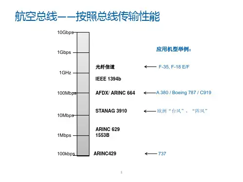
arinc717总线定义ARINC 717总线是一种用于航空电子系统中的数字数据总线。
它由美国航空电子工业协会(ARINC)制定,旨在提供高速、可靠和安全的数据通信。
ARINC 717总线广泛应用于飞机上的数据传输和信息交换。
ARINC 717总线采用差分信号传输数据,具有高抗干扰能力。
它的传输速率可达到每秒100Kbps,能够满足航空电子系统中的高速数据传输需求。
此外,ARINC 717总线还具有可靠性高、实时性强的特点,能够确保数据的准确和及时传输。
ARINC 717总线的主要应用是在数据采集和数据转换系统中。
它可以连接各种航空电子设备,如飞行管理计算机、导航系统、显示系统等,实现它们之间的数据交换和共享。
通过ARINC 717总线,飞机上的各个系统可以实时地传输信息,并进行相应的控制和调度。
ARINC 717总线还具有灵活性和可扩展性。
它可以支持多个节点的连接,通过总线控制器进行数据的发送和接收。
此外,ARINC 717总线还支持多个优先级的数据传输,可以根据不同的应用需求进行灵活配置。
ARINC 717总线的通信协议是基于硬件的,包括电气特性和物理层接口。
它采用差分信号进行数据传输,具有较好的抗干扰能力。
在物理层接口上,ARINC 717总线采用了BNC型连接器,方便了设备之间的连接和拆卸。
在ARINC 717总线系统中,总线控制器起着重要的作用。
总线控制器负责控制数据的发送和接收,以及数据的优先级和时序的管理。
总线控制器还可以对数据进行校验和纠错,确保数据的可靠性和完整性。
总的来说,ARINC 717总线是一种在航空电子系统中广泛应用的数字数据总线。
它具有高速、可靠和安全的特点,能够满足航空电子系统中的数据传输需求。
通过ARINC 717总线,飞机上的各个系统可以实时地传输信息,并进行相应的控制和调度。
它的灵活性和可扩展性使得它在航空电子领域具有很大的应用潜力。
航空电子系统的自动化测试应用摘要:自动化测试技术为航空电子系统的验证提供了支持,在测试工作实施之前,需要根据实际情况统筹考虑各自动化测试技术的优缺点,选择合适的测试方法;同时,趋于集成度高、结构复杂的综合模块化航空电子系统对自动化测试手段提出了更高的要求,促进自动化测试技术的进一步发展。
关键词:航空电子系统;自动化测试;应用1自动化测试的概念和意义随着技术的发展,航空电子设备越来越趋向于小型化、集成化,航空电子系统由各子系统相对独立的联合式系统发展为集成度高、结构复杂的综合模块化航空电子系统,系统测试日益复杂。
传统的手工测试难以满足日益复杂的航空电子系统验证需求,传统的手工测试中大量枯燥的重复操作增加试验人员的误操作几率和试验周期。
自动化测试指的是用机器执行代替人为驱动的测试行为。
它在预定条件(包括正常条件和异常条件)下运行系统或软件,评估运行效果。
自动化测试的意义在于:①优化成本:降低劳动量,降低测试成本;②可靠:提高测试的全面性,提高测试精确度;③快速:加快测试速度,缩短测试周期;④规范化:提供规范化的测试流程;⑤可重用:提高测试的重用性。
2自动化测试应用及方法概述航空电子系统中的自动化技术主要应用在接口测试自动化和仿真控制与仿真模型调参。
其中,接口测试自动化包括面向ICD的自动化测试和激励响应式的测试;仿真控制与仿真模型调参包括仿真启停控制、仿真模型状态切换和仿真模型参数调整。
常见的自动化测试方法有记录回放(Recordandplayback)、线性脚本(Linearscripting)、模块化脚本(Modularscripting)、数据驱动测试(Data-driventesting)、关键字驱动测试(Keyword-driventesting)等。
3自动化测试技术的应用现状以采用基于关键字驱动测试方式的柔性测试系统为例,在研制阶段作为调试工具,辅助研发人员进行系统的调试、半实物仿真测试和功能逻辑验证;测试阶段作为测试工具或验收工具,辅助测试人员进行系统的出厂测试或验收测试;集成阶段作为集成验证平台,辅助系统工程师进行多设备的集成、功能确认和故障定位;维护阶段作为检测验证工具,辅助维护人员进行故障定位、问题确认和复现。
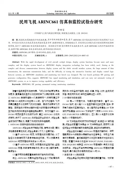
飞机航电系统测试方法设计研究随着我国民机事业的蓬勃发展,民机的产量日新月异的提升,因此在生产现场,迫切需要一种能够实现综合航电全系统,全功能,全方位检测的测试方法,本文着重就实现民机航电系统综合测试设备设计研究进行阐述。
标签:民机;航电;测试1 航电测试设备功能简介航电系统综合测试设备能够验证飞机航电系统内部各子系统之间,系统与有关交联设备之间接口关系的正确性,检查显示控制逻辑的正确性,并能仿真系统所需的各种总线信号、离散量及模拟量信号,实现航电系统的装机前试验以及系统故障的排查。
2 航电测试设备总体实现思路各个分系统产品通过专业测试电缆引至对应得系统交联箱,交联箱内部放有馈线端子排将各种所需要的引至另一系统的信号引出至机箱后面对应的连接器上,该连接器又通过交联电缆与另一系统的交联箱连接,而且系统输出的ARINC429数据也通过馈线端子排引出至开关切换箱,按照此设计思路,就可以将至少12个子系统的所有信号交联起来,交联箱的设计依据是航电系统的机上连接图,将需要监控的至少150路ARINC429数据分成20组,每次可以监控至少20路ARINC429数据,这20路信号由监控计算机的软件界面进行选择,而需要仿真的信号由仿真计算机控制通过仿真箱送入各个子系统,仿真具备手动和自动两种工作方式,自动模式由仿真机自动产生固定高度和连续变化的高度来模拟飞行状态,手动模式能够根据手动输入的高度进行模拟,硬件和软件都采用模块化设计。
在设计时留有一定量的余量便于维护和升级。
现在以下几个方面进行阐述。
(1)系统供电:各个子系统、部件所需的供电电源通过监控机柜上的电源监控箱提供,断路器箱面板上安装各个部件的断路器为联试成品进行过载保护。
(2)监控与仿真的实现方法:能够仿真部分部品输出的ARINC429数据,以满足在部分部品缺少时的航电系统联试需求,需仿真的电流电压信号通过工控机内部的NI-PCI-6704模拟量输出板卡提供,转速信号的仿真通过安捷伦33522A 提供,离散量、矩型短波以及电阻信号通过专用板卡安装于信号交联机柜内,通过仿真工控机的485总线程控通道复用开关和选通开关,将仿真信号送往联试的航电系統进行仿真数据的配置。
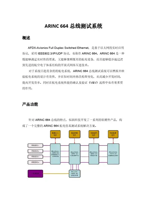
ARINC 664总线测试系统概述AFDX-Avionics Full Duplex Switched Ethernet,是基于以太网的实时应用协议,采用IEEE802.3/IP/UDP协议,也称作ARINC 664。
ARINC 664是一种既能够满足实时性的要求,又能够兼顾既有的航电设备,而且能够稳步地过渡到先进的航空电子体系结构的开放式网络互连技术。
对于系统日趋复杂的的航电系统,ARINC 664总线测试系统可以模拟并检验航电系统的设计有效性,并在短时间内修改构型变化,从而减少开发时间,提高开发效率。
同时在航电系统性能的确认及验证(V&V)流程中也有着重要的作用。
产品功能针对ARINC 664总线的特点,恒润科技开发了一系列的软硬件产品,构成了一个完整的ARINC 664航电仿真测试系统解决方案。
• 产品特征:♦统采用1000M以太网进行控制,系统构建的灵活性大;♦系统内的不同设备可以相互组合以构成更加完备的测试与仿真应用;♦全部采用1U上架结构类型,满足机柜内高密度布置的需要;♦充分考虑测试与仿真的需要,多种设备具有对数据的采集与监控功能;♦具备外部触发和IRIG-B码时统功能,满足全网同步的需要。
产品优势及介绍ARINC 664总线测试系列产品是在充分理解ARINC664协议的基础之上,采用先进的可编程逻辑技术和独特的算法来实现。
产品无论是在协议覆盖率还是在设备性能指标上都在国内处于领先水平,拥有完全的自主知识产权。
产品已经应用于实际的项目,经过了市场的检验,产品的技术成熟度和稳定性有可靠的保障。
• HiwaySwitch-ARINC 664仿真测试交换机单机可提供8/16/24个ARINC664接口。
• 性能指标:♦多级流水线工作的交换引擎,内部交换带宽4Gb/s;♦真正实时交换,绝对交换延迟小于1us;♦支持交换机的MAC和IP地址设置;♦支持4096个虚拟链接配置,子虚拟链接数量不限;♦通过虚拟链接(VL)和带宽分配间隔(BAG)实现流量控制;♦过滤:►字节完整性检查;►CRC32校验字检查;►源/目的MAC地址检查;►帧长度检查;►目的地址有效性检查;♦触发与时统信息:►针对接收到的数据帧提供1us分辨率的相对时戳信息;►内置IRIG-B解码器,提供绝对时统信息;►通过外触发实现本地计时器清零;♦用户感兴趣数据通过1000M以太网实时上传;♦交换机的错误统计信息通过1000M以太网实时上传;♦支持用户感兴趣虚拟链接数据(Virtual Link)的上传与采集分析;♦支持2种配置信息加载模式:配置模式和编程模式;• HiwayInject-ARINC 664总线故障注入与监听设备单机可同时提供12个ARINC 664通路的故障注入与数据监听功能。
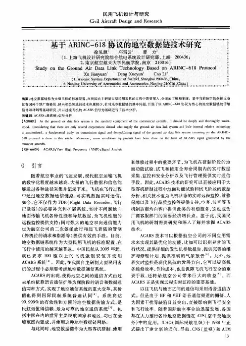
飞机维修中电子测试技术的应用甘长明摘要:飞机的使用寿命和正常起飞等方面在很大程度上受到日常检修和维修工作的影响。
本文,主要是分析和研究了飞机维修过程中电子测试技术的实际应用。
关键词:电子测试技术;飞机维修;自动测试设备引言:在我国航空技术水平不断发展的过程中,民航飞行运行的安全性成为了大家重视的话题之一,为了保证飞机的飞行安全,就要不断提升飞机各项系统的状态监控能力及性能检测水平,还要提升对各种飞机故障的诊断水平。
而电子测试技术在对飞机维修工作中均能实现这些要求,为民航飞机安全飞行与运营提供了重要的保障。
电子测试技术与微电子技术与传感器等技术相结合,在实际应用的过程中,主要体现在“预防为主”的维修原则基础上,本文将对电子检测技术在民航发动机维修中的实践运用进行分析。
一、电子测试技术飞机的发明与诞生为人类社会的文明进步起到了有效的推动作用,大幅度的提升了交通工具的运用效率,并在战争时期起到了极为重要的作用。
但是由于飞机自身行驶的特殊性,一旦发生飞行故障,将会对飞机所承载人员的生命安全造成毁灭性的打击。
而当今时代背景下,民航飞机成为了人们经常使用的交通工具,因此,对民航飞机的日常检修与保养工作受到了广泛的关注。
作为飞机设备中主要的构成模块,电子设备对飞机的安全运行起到了重要的影响作用,电子检测技术主要是针对飞机主机的电子系统模块,对故障进行检修的一种先进技术方式。
在电子测试技术的应用下能够快速的检测出飞机主机电子系统中出现的故障,并针对具体的故障快速进行维修二、飞机常规维护检测项目为了能够保障飞机设备飞行运营的安全性,本着对乘客生命安全负责的理念,通常情况下,在民航飞机飞行运输的过程中,会进行三次常规性的维修检修工作。
一般情况下会在飞行前、过站及飞行后进行。
除此之外,民航飞机还会接受定期的维护检修,并根据飞机的飞行状况,具有针对性对重要零部件进行维护检修。
在飞机维护检修的过程中,每当飞机飞满500 小时,就会接受发动机的定期检查。
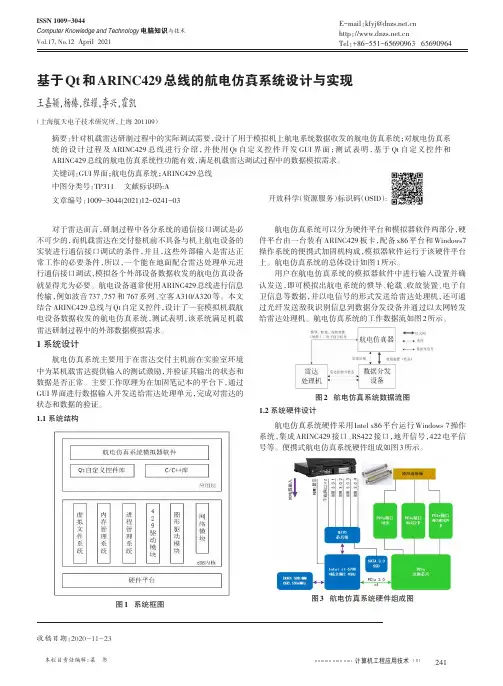
计算机工程应用技术本栏目责任编辑:梁书基于Qt 和ARINC429总线的航电仿真系统设计与实现王嘉颖,杨榛,程耀,李兴,霍凯(上海航天电子技术研究所,上海201109)摘要:针对机载雷达研制过程中的实际调试需要,设计了用于模拟机上航电系统数据收发的航电仿真系统;对航电仿真系统的设计过程及ARINC429总线进行介绍,并使用Qt 自定义控件开发GUI 界面;测试表明,基于Qt 自定义控件和ARINC429总线的航电仿真系统性功能有效,满足机载雷达调试过程中的数据模拟需求。
关键词:GUI 界面;航电仿真系统;ARINC429总线中图分类号:TP311文献标识码:A文章编号:1009-3044(2021)12-0241-03开放科学(资源服务)标识码(OSID ):对于雷达而言,研制过程中各分系统的通信接口调试是必不可少的,而机载雷达在交付整机前不具备与机上航电设备的实装进行通信接口调试的条件,并且,这些外部输入是雷达正常工作的必要条件,所以,一个能在地面配合雷达处理单元进行通信接口调试,模拟各个外部设备数据收发的航电仿真设备就显得尤为必要。
航电设备通常使用ARINC429总线进行信息传输,例如波音737、757和767系列、空客A310/A320等。
本文结合ARINC429总线与Qt 自定义控件,设计了一套模拟机载航电设备数据收发的航电仿真系统,测试表明,该系统满足机载雷达研制过程中的外部数据模拟需求。
1系统设计航电仿真系统主要用于在雷达交付主机前在实验室环境中为某机载雷达提供输入的测试激励,并验证其输出的状态和数据是否正常。
主要工作原理为在加固笔记本的平台下,通过GUI 界面进行数据输入并发送给雷达处理单元,完成对雷达的状态和数据的验证。
1.1系统结构图1系统框图航电仿真系统可以分为硬件平台和模拟器软件两部分,硬件平台由一台装有ARINC429板卡,配备x86平台和Windows7操作系统的便携式加固机构成,模拟器软件运行于该硬件平台上。
CJ818飞机无线电通信、导航、监视综合系统
安乐;田甜;董勤鹏;崔德刚
【期刊名称】《民用飞机设计与研究》
【年(卷),期】2009(0)S1
【摘要】国外最新民航客机如B787和A380的航电系统设计多采用模块化和综
合化的思想。
民航飞机的无线电通信、导航、监视(CNS)系统可实现飞机与外界信息交流的功能,例如语音通信、卫星导航和配合空中交通管制等。
我国大飞机项目
启动后,在与民航飞机相关的各个领域内实现技术突破、建立拥有我国自主知识产
权的产品线成为一项重要的工作内容。
介绍一种用于CJ818飞机上的无线电通信、导航、监视综合传感系统,该系统具备模块化、综合化的特点,可提高系统的可靠性
和降低生命周期成本,符合民航飞机安全性、经济性的要求。
【总页数】3页(P131-133)
【关键词】综合航电;CNS;CJ818
【作者】安乐;田甜;董勤鹏;崔德刚
【作者单位】上海飞机设计研究所;北京航空航天大学大型飞机高级人才培训班【正文语种】中文
【中图分类】V243
【相关文献】
1.基于星基的r民用航空无线电通信、导航、监视系统发展现状 [J], 王洪全;刘天华;崔凯;罗斌;欧阳承曦
2.民用航空无线电通信、导航、监视系统发展现状 [J], 张鑫燕
3.民用航空无线电通信、导航、监视系统发展现状研究 [J], 高健;陈明锐
4.通航飞机通信导航监视系统数字建模浅析 [J], 王晋誉
5.面向切面思想的无线电通信导航监视系统设计与分析 [J], 雷国志
因版权原因,仅展示原文概要,查看原文内容请购买。
ARINC-818 TESTING FOR AVIONICS APPLICATIONSKen BissonAIM-USA34 Country RdE Hampstead, NH 03826(603) 378-0957bisson@Abstract - The ARINC-818 Specification is an industry standard that defines a digital video interface link and protocol that is used for high-speed digital video display data communications. This Specification enables data generation units and display devices working in Aerospace applications to utilizea common link and protocols that supports high-bandwidth data specifically for digital video applications. Aerospace applications currently utilize many different video formats. Video formats differ in their Frame Rates, resolution, pixel density, and interlacing techniques. The ARINC-818 Specification defines how all these video formats are built and mapped to the industry standard Fibre Channel. This paper provides an overview of the ARINC-818 link and protocols being used for Avionics. The paper also discusses the practical testing of an ARINC-818 network, and the testing challenges associated with this high-speed/high data rate application.INTRODUCTIONAvionics applications are increasingly using more and more displayed video data. The high-bandwidth video data, that comes in large amounts, must be integrated into the avionics communications network. To date most avionics applications rely on proprietary hardware to merge the video display and data that are routed over separate networks. There are commercial standards for the avionics data communications, like ARINC-429 and ARINC-664, but these are simply not fast enough for video data.A commercial standard called ARINC-818 has been defined for high-bandwidth video data in commercial aircraft applications. The ARINC-818 Specification is based on the Fibre Channel standard (FC). Fibre Channel combines the ability of moving large amounts of high-bandwidth data like computer busses, with the routing and protocol capabilities found in networks. In addition, Fibre Channel includes redundancy and deterministic behavior that is required for Avionics applications.The Fibre Channel standard defines the physical protocol (how to route the data) separately from the application protocol (how the data is organized). The standard identifies layers that are used for moving data. These layers define the physical connections, data encoding, and routing needed to pass data between devices. In addition, Fibre Channel defines an FC-AV (Audio/Visual) Upper Layer protocol which maps audio and video data onto a Fibre Channel network. The ARINC-818 Specification refines the FC-AV with specific definition of the amount and types of digital video data for the most common standard video interface types.ARINC-818 has been adopted by Boeing on its 787 commercial aircraft program, and Airbus on its A400M program.ARINC-818 OVERVIEWThere are three reasons why ARINC-818 is a great fit for avionics applications:o Simple to implemento Fast and scalableo Separates physical protocol from application protocolARINC-818 defines an application protocol working on a Fibre Channel closed network topology. In order to understand ARINC-818, onemust also understand Fibre Channel. Likewise, when performing testing of ARINC-818 applications, it is essential to understand and be able to perform Fibre Channel testing as well.Fibre Channel separates functional areas into layers. There are five (5) layers illustrated in Figure 1.FC-AV is the Upper Layer protocol defined in layer 4. ARINC-818 further refines the FC-AV definition.Simple to ImplementThe primary elements of the ARINC-818 topology are End Systems, which are networked together in a point-to-point connection. The End-Systems will either be a data source, or a Receiver (Display Unit). Fibre Channel Data Switches can be used for routing if multiple connections are required. But even with a switch for routing, all links are treated as point-to-point connections.The physical interface for a Fibre Channel port is simplex, unidirectional, serial connections. One line for transmit, another for receive. These are lightweight, and easy and maintain. There are no large multi-pin cable bundles and connectors. Either optical or standard copper cabling can be used. The choice of media type is dependent upon distance, power requirements, and weight. The physical media options, with no degradation of performance is a real benefit to the Avionics design engineer.For testing, the test equipment must be able to simulate End Systems. This means having the flexibility to also accommodate the various Fibre Channel physical interfaces. In addition, the test equipment must be able to insert itself in-line between the End Systems. There are many different splitters and taps available for copper and optical media to do this without affecting signals.Fast and ScalableFibre Channel is extremely fast. Currently, 1, 2, and 4 Gbps speeds are all in use today. The Fibre Channel roadmap calls for an increase in speed to 16 Gbps in the next few years. Since each end system has access to the full bandwidth, Fibre Channel links can easily support a multitude of high-bandwidth display applications.Avionics applications can choose from a wide variety of display characteristics to meet their needs. ARINC-818 defines the data network to meet these display requirements today, and it includes the provisions for future upgrades. Figure 2 shows the relationship between the various display resolutions and data bandwidth [1].Figure 2 – Video Display ResolutionsSeparates physical protocol from application protocolThe Fibre Channel standard defines the protocol (how to route the data) separately from the ARINC-818 application protocol (how the display data is organized). Each has its own unique characteristics. The ARINC-818 Specification only defines the Upper Layer Protocol that is mapped onto Fibre Channel. In fact, it would be possible to route multiple types of protocols (for example ARINC-818 and IP) simultaneously over the same Fibre Channel network.Fibre ChannelAs stated previously, in order to understand ARINC-818, one must also understand Fibre Channel. Fibre Channel, like a network architecture, transmits blocks of user information called packets . Before sending the data over the physical link, additional Fibre Channel specificFC-0 Physical: Cabling, connectorsFC-1 Transmission Protocol: Encoding, word transmission, error detectionFC-2 Protocol: Frame layout, flow control, class of service FC-3 Common Services: Frame layout, flow control, class of serviceFC-4 Mapping of Protocols: Application protocol mapping to Fibre ChannelFigure 1 – Fibre Channel Layerscontrol information is added to the packet. The combination of the control information and the data is called a frame. For Fibre Channel a frame has 24 bytes of control information (header) and anywhere from 0 to 2112 bytes of payload (pure data containing the user information). If a packet of user information is too large to send in one frame, then multiple frames must be grouped together and this forms a sequence.Besides frames of data, Fibre Channel also identifies other types of data to be sent over the link. This type of data is called ordered sets. Ordered sets are Fibre Channel’s mechanism to perform control and signaling functions over the simplex transmission link. There are three (3) types of Ordered Sets:o Frame delimiters – identify start/end of frameso Signals – indicate events or actionso Primitive Sequences – indicate states transmitted until something changes Preceding any frame of data, is a Start Of Frame (SOF) delimiter. Likewise, every frame is followed by an end of frame delimiter (EOF). Lastly, there must be a minimum of 6 ordered sets (most likely fill words) between the transmissions of frames. The most common fill word is an IDLE. Figure 3 shows the FibreARINC-818ARINC-818 maps the display video data format onto the payload of the Fibre Channel frames. In order to understand the mapping protocol, one must understand a little about digital video frames. A digital frame is a 2 dimensional image made up multiple rows of individual pixel data that display horizontally in a visible display. Digital display formats vary by the amount of rows, the number of rows, and the amount of bits per pixel. For example, an SVGA PC display is 1280 rows x 800 pixels in a row. The bits per pixel usually identifies the color resolution. So, the amount of data needed to generate a single 1280x800 frames with 16-bits per pixel color is 1.6 Mbytes. Digital Displays are also generally scanned vertically; which means that data starts from the top and progressively scans to the bottom. Frames delivered to the Digital Display have to be ordered in the same fashion. In addition to the data, there are timing elements that must be met. Digital Display must be synch’ed vertically and horizontally. There must be an identifiable, consistent timing pattern associated with the display of each consecutive row (horizontal sync) and also every time the display data reaches the bottom of the display it starts again at the top. For example, a common vertical sync is a 30Hz display. By adding the amount of data contained in a single display, and combining the requirement of updating this amount of data at 30 Hz, it is clear to see why a high-bandwidth, low latency network is required.In the ARINC-818 Specification, each digital display frame is called a container. The container is made up of a header and objects. Objects are the data elements of the container. There are four (4) types of objects:o Object 0: Ancilliary Datao Object 1: Audio Datao Object 2: Video Data (Progressive Scan)o Object 3: Video Data (For Interlaced Displays)Since the container is larger than what a single Fibre Channel frame can hold, the container is transferred as multiple data objects. In addition, most single digital display lines will also exceed the payload of a single Fibre Channel frame, so multiple data objects may be used to transmit one digital display line. Figure 4 shows how a single container and its objects are defined.Each object is embedded in the data payload of a Fibre Channel frame. Object 0 contains the container header information. The container header is 22 bytes of data that describes the container and summarizes the objects that will follow. For example, information included in the header is a definition of the frame rate, frame type, number of objects that are used in the container. The header also includes the CRC value of the previous container. Figure 5 illustrates the container mapping to the Fibre Channel frames [2].TESTING ARINC-818Testing is a critical element for the process of integrating any avionics system. It is important to completely understand the behavior of each individual component and the whole system during normal operations, as well as behaviors and reactions to system faults. Testing is required to understand the movement of data over the ARINC-818 network as well as understanding the data that is being passed. Testing will occur in two phases:o Testing individual End Systemso Testing End Systems in the ARINC-818NetworkIndividual End System TestingAvionics Digital Display Systems are delivered tothe airframe manufacturer from many suppliers. Each Display specializes in a particular functionfor the aircraft (i.e. Navigation, Collision Avoidance Radar, Health Maintenance). Individual testing is required for the Display Systems and data generator End Systems. Therefore, an ARINC-818 Test System must be able to simulate the data source and/or simulate the Digital Display. Testing associated with ARINC-818 End Systems include:o Do the Source data End System portstransmit correct containers at appropriate sync intervals?o How many transmit errors are producedover a long time period?o Does the Display receive and processobjects correctly?o How does the Display System react toreceiving incorrect Objects, frames with protocol errors, CRC errors, or frames with bad data in them?Network System TestsIndividual End Systems are eventually integrated into an avionics ARINC-818 network. Effective testing is required during integration to insure that the End System operates efficiently. This type of testing requires that the test equipment is placed in-line between the data source, and the Digital Display. Network frame flow testing reveals flaws in the system design and implementation. Testing associated with checking the ARINC-818 network frame flow include:o Monitoring each End System for frameerrors associated with frame movement over the network.o Checking the deterministic flow ofcontainers from the End System source. o Checking the redundancy of the network(if implemented). o Checking the ARINC-818 networkreaction and tolerance of errors.CHOOSING AN ARINC-818 TESTSYSTEMThere are commercially available Fibre Channel Protocol Analyzers and Digital Frame Grabber interfaces that can perform various degrees of ARINC-818 testing. Fibre Channel protocol Analyzers are effective for testing Fibre Channel protocol errors only. They are not capable of monitoring Objects within the Fibre Channel data payload of the frame in real-time. Likewise,Digital Frame Grabbers can display at various formats, but cannot decipher Fibre Channel protocol or network timing errors.An ARINC-818 test system requires the use of interfaces specifically designed for FibreVideo FrameContainerFigure 5 – Container maps to Fibre Channel framesChannel and Digital Display applications. This system will perform all of the necessary protocol analysis, and have the capability of examining the Fibre Channel Link information and Object frame data in the payload in real-time. I have found that there are currently only two (2) commercial manufacturers of these products available.The Test System will perform 3 different types of tests. These are:1. Traffic Generation2. Traffic Monitoring3. Digital Display OperationTraffic GenerationTraffic Generation is the ability to produce Digital Display containers from a single port, or redundant ports. The Containers will be sent using a Fibre Channel network to a Digital Display End System. It is important to test multiple types of container frames, and the ability to generate payload (display) data. The setup of the Virtual Link for simulation will include the following actions:o Constructing Object 0 Headero Constructing Object 1, 2, or 3 Datao Implementing the Network connection (single or redundant)o Sending objects with precise timingThe traffic generator needs to implement a robust scheduler capable of sequencing objects. The intermessage gaps between Objects needs to be programmable to a minimum of one (1) transmission word, 4 bytes, over the Fibre Channel network. This enables manipulating the digital display vertical and horizontal sync parameters and determining tolerances at various display rates.For example, consider a Digital Display that runs at 1024 rows by 768 pixels per row, 24-bits per pixel. The Display operates at a 30Hz update rate, and it is a progressive scan device (every line is updated sequentially). ARINC-818 maps this display’s Object 2s onto 1536 Fibre Channel frames. Figure 6 illustrates the precise time sequence in order to maintain vertical and horizontal sync.Fill words are used (most notably IDLES) to fill in the gaps between Fibre Channel frame transmissions. The amount of IDLE fill words between the End of Frame (EOF) and the start of the next frame (SOF), is used to govern the vertical and horizontal sync characteristics of the frame. The data generation simulator must have the ability to adjust the number of IDLE fill words. The most flexible ARINC-818 traffic generation testers will be most capable of manipulating data at the Fibre Channel word level. In order to support multiple types of digital displays, the test equipment must have the ability to control the fill words used for timing.Error injection associated with traffic generation is important to see how the Display End System will behave to various error conditions. The types of error injection include:o Fibre Channel Frame level errors (CRC, wrong byte alignment, size)o Incorrect Container CRCso Incorrect sequencing of frames andObjectsFigure 6 – 1024x768, 30 Hz, 24-bitA last important feature of the Traffic Generator is the ability to operate at “non-standard” Fibre Channel rates. As described previously, ARINC-818 uses a standard Fibre Channel rate (i.e. 1Gbps, 2Gbps…) and maps its objects to it. Fibre Channel Fill words (IDLES) are used to adjust the timing to the specific display. There are Digital Displays made that expect digital data input at fixed rates, not corresponding to standard to Fibre Channel. It is important for the Traffic Generator to be able to adjust its baud rate to these non-standard rates. These types of displays do not adhere to the ARINC-818 Specification, but they are common, commercially available products.In-line Traffic MonitoringTraffic Monitoring is the ability to look at and capture all frames of data traversing the network. The ability to monitor traffic in chronological order, including IDLES is important for monitoring anomalies. A complete analysis of the network can be accomplished by looking at the traffic over time. This information will yield how efficiently containers travel over the network. It is equally important for measuring an End Systems’adherence to ARINC-818 timing specifications for the particular Digital Display type.For Monitoring tests, the test system needs to have a programmable capture mode. This provides the ability to begin capturing data based on an event. The event can be an error condition,a specific Start of Frame, or even a portion of digital data embedded within the payload. Programmable capture enables trapping infrequent errors so that network behavior that prompts these errors can be analyzed and repaired.The Monitor operational tests need to have the capability of storing data for long captures over time. ARINC-818 applications generate a lot of data, so the capability of filtering some of the data in hardware before archiving is needed. Atest system that can store gigabytes of data ontoa disk file for later review is vital. Archived disk files can be analyzed in detail, post operation. Receive OperationsThe Receive operational testing consists of receiving digital display frames from a Fibre Channel port just like an End System. These tests can be conducted by simulating the Display End System, or by “shadowing” the actual receiving Digital Display End System. Shadowing simply means connecting to the same physical port connection as the Receiver End System using a network splitter or tap, and acquiring the incoming frames simultaneously with the Receiver End System. For Receive testing, only the digital data frames are received. This is different from the Monitoring tests described previously where every frame and Fibre Channel fill word is captured. The intent of the Receive Operations testing is to gather and display the container information. Each incoming container is checked for CRC errors and statistics are kept of these errors conditions.The Receive operations tests can examine the ARINC-818 protocol by displaying the data visually. The test system must mimic the actual display, or be programmable to mimic the display attributes (i.e. VGA, XGA, DVI…) The ability of the test system to look at the data contained within the payload to verify its integrity is the important test function.CONCLUSIONARINC-818 is a new Specification forimplementing a Digital Display network in Avionicsapplications. The ARINC-818 Specification isbased on a Fibre Channel network architecture.Fibre Channel defines the topology andimplementation of the network. ARINC-818defines the protocol that defines the digital displayinformation and its mapping to Fibre Channel.These standards specifically address movinghigh-bandwidth, low latency data, reliability andwith determinism. These are key requirements forAvionics communications.ARINC-818 Test Systems need to verify andmonitor the behavior of the ARINC-818 networkwhich requires doing more than just examining thedigital display. Tests include traffic generation,chronological monitoring, and simulating EndSystems receiving ARINC-818 containers. Thesetests require Fibre Channel testing, as well as justchecking the integrity of the digital display data. Itis most important to look at timing within thenetwork. The efficiency of the data traversing theARINC-818 network is more important than thesimple measurement of protocol faults that occurover time.References[1] Avionics Digital Video Bus, High Data Rate– Draft 3of project Paper 818, Airlines ElectronicEngineering Committee, June 24, 2006, page 4.[2] Avionics Digital Video Bus, High Data Rate– Draft 3of project Paper 818, Airlines ElectronicEngineering Committee, June 24, 2006, page 9.[3] Avionics Digital Video Bus, High Data Rate– Draft 3of project Paper 818, Airlines ElectronicEngineering Committee, June 24, 2006.[4] ANSI INCITS 230-1994 (R1999), InformationTechnology - Fibre Channel - Physical andSignaling Interface (FC-P H) (formerly ANSIX3.230-1994 (R1999)) (includes supplements)[5] ANSI INCITS 356-2002, Information technology -Fibre Channel - Audio Video (FC-AV)[6] Kembel, Robert W., “Fibre Channel AComprehensive Introduction”,Northwest LearningAssociates, 2002.[7] Information Technology – Fibre Channel – AudioVideo (FC-AV), T11/Project 1305-D/1.3, NCITS,May 1, 2000.[8] Kelley, Timothy, “ARINC 818 Becomes the NewProtocol Standard for High-Performance VideoSystems”, Great River Technology, COTS Journal,December 2006, /home/article.php?id=100602&pg=1.[9] Fibre Channel Speed Chart, Fibre Channel IndustryAssociation,/OVERVIEW/Roadmap.html.。