ANatural-Gas-FiredThermoelectricPowerGenerationSystem
- 格式:pdf
- 大小:371.48 KB
- 文档页数:5
第五届“学府杯”翻译竞赛原文(英译汉)Smart Energy Solutions: Increase RenewablesA variety of energy sources can be used to generate electricity, including coal, natural gas, nuclear power, and renewable resources like wind, water, plants, and the sun. Our energy choices have direct implications for our health, our environment, and our climate —and right now we are dangerously dependent on coal and other fossil fuels for most of our electricity needs.Coal is abundant and more equally distributed throughout the world than oil and gas. Global recoverable reserves are the largest of all fossil fuels, and most countries have at least some. Moreover, existing and prospective big energy consumers like the US, China and India are self-sufficient in coal and will be for the foreseeable future. Coal has been exploited on a large scale for two centuries, so both the product and the available resources are well known; no substantial new deposits are expected to be discovered. Extrapolating the demand forecast forward, the world will consume 20% of its current reserves by 2030 and 40% by 2050. Hence, if current trends are maintained, coal would still last several hundred years. However, coal is the worst offender, a dirty energy source that produces less than half our electricity but more than 80 percent of all power plant carbon emissions, along with significant and harmful levels of pollutants that degrade our environment and adversely impact our health.There’s a better, cleaner way to meet our energy needs. Renewable energy resources like wind and solar power generate electricity with little or no pollution and global warming emissions. To move the world toward a cleaner, healthier energy future, we need smart policy decisions focused on two primary goals: Increase renewable energy and decrease the use of coal.Support for renewable energy is growing worldwide and at the beginning of 2014, the governments of 144 countries have set renewable energy targets, almost a ten-fold increase since 2005 when only 15 countries had policies in place. Emerging and developing economies are leading the way, with 95 of them having renewable energy policy plans, according to the Renewable 2014 Global Status Report.The world generated 22.1 percent of its electricity from renewable sources in 2013, even though governments in the EU and US reduced their support. Renewable energy provides 6.5 million jobs worldwide, the report said.China, the US, Brazil, Canada, and Germany are the top renewable power countries in 2013, with Spain, Italy, and India making huge strides, according to the report. Denmark leads per capita power generation, and Uruguay, Mauritius, and Costa Rica were among the top investment locations.The most significant growth is in power generation, as global capacity jumped 8percent to more than 1,560 gigawatts (GW) in the last year. Hydropower rose by 4 percent to 1,000 GW, and overall renewables grew 17 percent to more than 560 GW.Over 140 countries have adopted new renewable energy targets, including the United States, which has pledged to increase renewable energy capacity 50 percent by 2020. President Obama has promised to slash America’s dependence on coal, and to switch power plants towards cleaner energy.However, it will be difficult for America to switch off coal consumption, as many states depend on it for their economic livelihood. Many lobbying groups are protesting the new clean energy act, saying it unfairly deprives local industries. Even though coal is a proven dirty energy source consumption has reached a 44-year high. Alternative and clean energy is no longer just a hip trend among environmentalists, but a real energy solution that provides power to homes and offices. The market has matured and become an attractive option for energy security. From the currently available technologies, solar photovoltaics, followed by wind power, concentrated solar power and geothermal, have the highest potentials in the power sector. The use of ocean energy might be significantly higher, but with the current state of development, the technical and economical potential remains unclear.Germany is pushing its economy towards renewables, and produces half of its electricity from solar power, The Local reports. In Denmark wind power meets 33 percent of electricity demand, in Spain 20.9 percent, and in Italy solar power meets 7.8 percent of electricity needs. Many cities across the globe have a goal to transition to 100% renewable energy.Over the last 5 years, solar power has on average expanded 55 percent per year, according to the report. Clean energy is becoming cheaper and more popular with consumers, and investors are snapping up the opportunity. Elon Musk, the entrepreneur who invested early in PayPal and the Tesla electric car, has put money into solar power, and Google is weighing a move into the renewables sector.Current levels of renewables development represent only a tiny fraction of what could be developed. Many regions of the world are rich in renewable resources. Spain and Portugal sit on a bed of geothermal energy, but currently use none of it. Scientists from the Renewable Energy Journal estimate Spain has the potential to produce up to 700 GW, which is five times the current electricity power generation of Spain.第五届“学府杯”翻译竞赛原文(汉译英)“圈子”没那么重要“刚才明明还在说笑,怎么我一走过来就闭嘴了,难道是在说我什么吗?”“看着同事们谈笑风生,我也想融入进去,可就是插不上嘴……”刚从学校踏入社会的职场年轻人,面对陌生的职场环境,往往会出现一段时期的“社交空窗”,总感觉自己被排除在圈子之外,融入不了主流群体之中,这也是年轻人最容易感到苦闷的事情。
热点13 核能的利用东北地区首个!辽宁红沿河核电站核能供暖项目正式供热2022年11月1日,辽宁红沿河核电站核能供暖示范项目正式投运供热,该项目是东北地区首个核能供暖项目,共惠及周边红沿河镇近两万居民。
红沿河核电站核能供暖示范项目以大连市瓦房店红沿河镇为试点,规划供热面积24.24万平米,最大供热负荷为12.77MW,利用红沿河核电站汽轮机抽汽作为热源,替代红沿河镇原有的12个燃煤锅炉房,实现红沿河镇清洁供暖。
项目新建一次管网近10公里,二次管网5.7公里,新建换热站4座。
据测算,该项目投产后每年将减少标煤消耗5726吨,减排二氧化碳1.41万吨、烟尘209余吨、二氧化硫60余吨、氮氧化物85余吨、灰渣2621吨,环保效益显著,将有效改善供暖区域大气环境,助力东北地区天更蓝。
红沿河核电站位于辽宁大连瓦房店市,是东北地区首座核电站和东北最大电力能源投资项目。
一期工程4台机组采用中国广核集团(简称中广核)具有自主知识产权的CPR1000核电技术,于2016年9月全部投产商运。
二期工程2台机组采用中广核全面升级的ACPR1000核电技术,2022年6月,红沿河核电站一、二期工程6台机组全面建成投产,成为国内在运装机容量最大的核电站。
红沿河核电站年度发电量可达480亿千瓦时,约占辽宁省全社会用电量的20%,能有效缓解东北地区阶段性电力短缺、稳定区域电力供应。
与同等规模燃煤电厂相比,等效于每年减少标煤消耗约1452万吨,减排二氧化碳约3993万吨,相当于种植10.8万公顷森林。
在安全稳定提供清洁电力的同时,红沿河核电主动创新、不断拓宽核能应用边界,积极研究推进周边社区核能供暖项目。
红沿河核电站核能供暖示范项目是东北地区清洁取暖的一项民生工程、民心工程。
红沿河核电将继续深入学习贯彻党的二十大精神,践行习近平生态文明思想,牢固树立“绿水青山就是金山银山”理念,深入打好蓝天保卫战,充分发挥清洁能源优势,保障核安全万无一失,为实现“双碳”目标、推进美丽中国建设作出更大贡献。
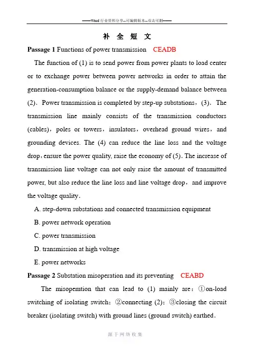
补全短文Passage 1 Functions of power transmission CEADBThe function of (1) is to send power from power plants to load center or to exchange power between power networks in order to attain the generation-consumption balance or the supply-demand balance between (2).Power transmission is completed by step-up substations,(3).The transmission line mainly consists of the transmission conductors (cables),poles or towers,insulators,overhead ground wires,and grounding devices. The (4) can reduce the line loss and the voltage drop,ensure the power quality, raise the economy of (5).The increase of transmission line voltage can not only raise the amount of transmitted power, but also reduce the line loss and line voltage drop,and improve the voltage quality.A. step-down substations and connected transmission equipmentB. power network operationC. power transmissionD. transmission at high voltageE. power networksPassage 2 Substation misoperation and its preventing CEABD The misopemtion that can lead to (1) mainly are:①on-load switching of isolating switch;②connecting (2);③closing the circuit breaker (isolating switch) with ground lines (ground switch) earthed.The“five preventings”for (3) includes:①preventing the wrong opening or closing of circuit breaker;②preventing the on load opening and closing of isolating switch;③preventing (4);④preventing the closing of circuit breaker with grounding wireconnected;⑤preventing(5).A. preventing the misoperation in substationB. the closing of grounding switch with power onC. accidents in the electrical operation of the substationD. the persons from illegal entering the lived bayE. the grounding wire (closing the grounding switch) with power on Passage 3A brief introduction on the development of supercritical boilers and their main advantages BDEACIn (1) such as U.S.A,Japan and European countries,the supercritical boiler has been developed since the 60s of last century.It has been proved by data and experience,the supercritical unit has (2).As for its reliability, because the steam-water flow passages in supercritical boiler is same as that in the (3),there isn’t anything special. But as far as hydraulic characteristic,a symbol of reliability, is concerned,in a supercritical boiler, under supercritical condition,medium is of single phase which has a (4). So that the problem caused by uneven distribution of steam phase and water phase can be avoided.It is admitted that, if (5),both supercritical and subcritical units can get anexcellent reliability index.A. good homogenization of distributionB. some advanced countriesC. whole process management is strengthenedD. great advantages oil economy and environmental protectionE. subcritical once-through boilerPassage 4 Steam generation and use BEADCSteam is one of man’s dependable servants More and more in the background,steam is doing more and more work for man. In (1) steam may be seen only at the teakettle, but the electricity used may be generated by burning coal or gas and producing steam to turn the generator rotors in the power plant Even if (2) by nuclear fission,the generation of electricity is still accomplished by (3).In the U.S.A. the demand for electricity doubles every ten years. For the most part water resources suitable for power generation are already in service, except for emergency standby and peak-load units; approximately 90% of (4) utilizes steam. The (5) is expanding in most countries of the world except for the countries where available water power resources are greater than power needs.A. first generating steamB. an electrically heated homeC. use of steam for electric power generationD. the new generating capacity being installedE. the fuel is uranium and the heat is suppliedPassage 5 Circuit breaker BDAECCircuit breakers are automatically operated high voltage (or high current) switches. Circuit breakers are required (1) by switching circuits on,by carrying load and by switching circuits off under manual or automatic supervision. Their duty is as follows:In closed position the circuit breaker must be a good conductor for the normal load current. In open position the gap across the contacts shall have foil insulation level. At opening operating the circuit breaker must be able (2) to many thousands of amperes,and independently of the characteristics from purely inductive to fully capacitive. At closing operation the circuit breaker must close fast and be safe also against full short circuit conditions. They must,therefore,be effective instantaneously when are called upon (3) without movement. As the circuit breaker is the last link in the chain of protective equipment, the circuit breaker reliability is (4) of the total electric power system so the importance (5) cannot be over emphasized.A· to perform any switching operation after long periodsB. to control electrical power networksC. of the circuit breakerD. to switch the current which can be from a few amperesE. of the highest importance for high reliabilityPassage 6 The ratio of distance to height of pumped-storage power plant BDACEFor pumped-storage power plant, generally the ratio of distance to height (l), Distance-height ratio (2) to the drop between upper and low reservoir that is L/H. The head of simple pumped-storage power plant consists of two parts,they are natural topographic elevation difference and elevation difference formed by dam. Of course, the head derived from topographic elevation difference ( 3 ),so in selecting plant site,the condition that not only a height difference is available but also no very high dam of upper reservoir is necessary should be considered. Smaller L/H value indicates a shorter water transportation line,then the engineering construction cost can be saved. But in many circumstances, topographic condition ( 4 ),so we can’t say the smallest L/H value ( 5 ). In newly constructed three large capacity pumped-storage power plants in our country, the L/H value respectively are:7.12 in Guangzhou. 4.12 in Shisanling,2.40 in Tian huangpingA. is most economicB. is used to evaluate topographic condition of power plantC. is not desirableD. is the ratio of horizontal distance between upper and low reservoirE. is the bestPassage 7 Fuel cells BAECDFuel cells are devices that when a fuel such as hydrogen or hydrogen-rich compounds and oxygen are supplied to materials arranged like the anode and cathode of a conventional battery, combine to convert chemical energy directly into electrical energy. Unlike conventional batteries. where the conversion of chemical to electrical energy requires only the closing of a circuit between the cathode and anode to produce and electrical current,(1). These cells require the fuel and oxygen that will produce the chemical reactions that produce an electrical 0utout.Fuel cells have been made that will supply power in the megawatt range,and (2).Such cells are not yet widely used on power systems,but(3)to supply fuel cell power to isolated loads As the voltage output of a cell is in the order of l to 2.5V, (4) and power output in ranges that are normally required. Inverters are used to (5) when and AC output is desired.A . further development is under wayB. there is no storage capacity in a fuel cellC. many cells are operated in series to obtain voltagesD. supply alternating current from fuel cellsE. as they are being developed there have been some applications Passage 8 Substations pace into the Digital Age CAEBDSubstations constitute the main part of power transmission and distribution in a power grid. The substations (1), with the responsibility for the electric power transmission and distribution in the grid. Over more than a decade of development, (2). In the rebuilding and constructing of power grid in rural and urban areas,automation technology is not only used in low-voltage substations to realize unattended operation,but also in the 220kV and above extra-voltage substations,thus greatly enhancing the level of modernization of power grid construction, strengthening the power transmission and distribution and the possibility of power grid dispatching and reducing the total cost of substation construction, (3). However, the development of technology is never-ending,and the increasing maturation of technology like intelligent switches,photoelectric current and voltage transformers,online condition monitoring of primary equipments, (4), as well as the development and application of high-speed network in real-time system,is bound to have a profound impact upon the existing substation automation technology, and (5) is about to emerge.A. substation automation technology has reached a certain levelB. simulation training technology for substation operationC. composed of a large number of primary and secondary equipmentsD. a full-digital automation systemE. all of which has become an indisputable factPassage 9 Overcoming the Problem of Waste CADEBMany large cities are anything but beautiful Streets are littered with trash. In this trash, however, (1) .If people want to solve the problem of waste, (2).They must work out ways of making use of good things which are just thrown away as waste.When a car gets too old,it may not rimany more. But if the metal that the car was made of is still good,(3). When a bottle is empty, it goes out in the trash. But bottle glass can be ground into sand and used to pave streets. Besides, garbage from food can be changed into fertilizer. But first you have to pick out all the glass and metal.Furthermore, garbage can also be a good source for making building blocks, which are then covered with concrete. Now, (4) . Some day, people will watch films in a great cinema which has been built out of garbage Future buildings,roads,and cities may be made from garbage. But so far, (5).A. there is no time to be lostB. building beautiful cities out of garbage is only a dreamC. there is still something that can be usefulD. it can be put to use againE. more and more machines are designed for this purpose Passage 10 Hibernation EBDACThe weather in winter. Call be very cold. Some animals sleep during the winter, for it's difficult for them to find food then. (1) . For example,their sleep can last from autumn to spring. (2).Animals need food in winter to keep them warm and alive If they move about more,they need eat more. (3). Their heart beats slowly. And they breathe slowly. They find a safe place to sleep. (4).In warm winter some animals like bears may wake up. If they see thick snow oil the ground, they will get back to their sleep. (5).A. So they don’t need to worry about bad weather and other dangerous animalsB. We call this kind of sleep in wintertime “hibernation’’C. As it gets warmer and warmer in spring,the sleeping animals begin to wake up and look around for foodD. Hibernating animals don’t need to eat much because they don’t moveE. They can sleep for a long timePassage 11 Satellites BDACEThe body that is neatest to the Earth is the moon. (1). This satellite is called natural satellite. Man—made spacecraft which circle the Earth are called artificial satellites. Natural as well as artificial satellites circle the planets in a definite path or orbit(轨道). (2).All the bodies in space like the moon,the planets and the stars alsoexert an attractive force on objects. (3). The moon’s gravitational force is only one.sixth that of the Earth’s. The Earth’s gravitational force of pull keeps ns and everything else on Earth from floating away to space.(4). There are many artificial satellites orbiting around the Earth. Some artificial satellites have been sent up to orbit the moon and even the planet Mars. (5).A. The bigger and heavier a body is, the greater is its force of gravityB. It circles the Earth and is therefore know as a satellite of the EarthC. To get out into space we have to overcome the Earth’s gravitational pullD. A satellite stays in orbit because the planet gravitational force keeps pulling it into a circleE. Artificial satellite can be used for various purposesPassage 12 Secondary equipment in power system BDEACThe secondary equipments in power system are (1), measuring,regulating,controlling primary equipments, the equipments that supply information,working condition for the operator or maintenance persons, and (2). The electric circuit connected with the secondary winding of CT or PT is called secondary circuit. The secondary equipment and secondary circuit belong to secondary system.The voltage and (3) are:110V , 220V DC operating voltages, 100V rated voltage of the potential transformer secondary winding and (4).The related parameter values of secondary system after weak electrification are:24V 48V 60V DC operating voltages, (5), 0.5A rated current of CT secondary side.A. 5A rated current of the current transformer secondary windingB. the equipments that provide protecting,monitoringC. 50V rated voltage of PT secondary sideD. the equipments that send the command signalsE. current values in secondary systemPassage 13 Switching overvoltage EABCDA sudden change in the configuration of transmission network caused(1) or by the appearance of a fault can cause a rapid surge known as switching overvoltage, which propagates throughout the network. It is these switching overvoltages which in general (2), Limitating these overvoltages is of extremely importance, because they have an important effect on both (3).These switching overvoltages can occur (4). If non-restriking circuit breakers is not used, it is at the instant of closing, and above all,re-closing of a line which has held a residual charge, that the strongest overvoltages will appear. This switching overvoltage is usually limited(5).A. determine the insulation requirements of transmission linesB. the cost of transmission and 1ine failure rateC. at both opening and closing of circuit breakersD. by means of circuit breaker closing resistor in 500kV systemE. by the operation of a circuit breakerPassage 14 Transmission line and distribution line ADBCEThe high voltage power line through which power is (1) is called power transmission line. The voltage classes of 35kV and above are generally used. High voltage distribution line is (2) to distribution transformers. Low voltage distribution line is the line that transmits power from distribution transformer to the users. The normal voltage of power distribution line is 380V.The special sections of (3) refer to the sections with large spanning, serious pollution, (4).The overhead line section whose span is 1000 m and longer or the height of the pole or tower is l00m and higher is called(5).A. transmitted from power plant’s step-up substation to step-down substationB. the overhead transmission lineC. lightning frequently happening and heavy rainingD. the power line that transmits the power from step-down substationE. 1arge spanning line sectionPassage 15 Transformer insulation CEABDThe insulation of a transformer can be categorized into internalinsulation and external insulation. (1). The external insulation is the insulation between the upper part of bushings and the ground and the insulation among the bushings. The internal insulation of transformer can be further subdivided into main insulation and longitudinal insulation (2). The longitudinal insulation refers the insulation between different parts of the same winding,such as insulation between different sections,layers and turns of the same winding.(3), insulating pressboard, cable paper, corrugated paper, etc. The oil in transformer has two functions, one is insulation, and the other is cooling (4) by the factors such as temperature is called insulation aging.(5), for every 6o C temperature rise the insulation life time of the paper used in transformer will decrease by half.A. The main insulation materials inside transformer are transformer oilB. The degradation of insulating properties of insulation materials under long period of influenceC. The internal insulation refers to the insulation of various parts inside the oil tankD.If the winding temperature is within the scope of 80~140 o CE. The main insulation refers to the insulation between windings and grounding parts and the insulation between windingsPassage 16 The electricity market BDAECThe aim of introducing market mechanism is to bring various parties more economic benefit through equitable competition,thereby promote economic development.Like other markets, it needs (1) where the sellers and buyers (suppliers) can trade electricity, and needs (2) where the suppliers can sell electricity to final customers. As in other markets,the participants need (3). Competition is introduced into generation and retail supplied to customers. Customers are free (4). If a customer chooses to buy electricity in the retail market, he should be able to choose electricity supply from one of several competing retailers. If a customer decides to purchase directly from the wholesale market, he will need (5). Power generation is disaggregated into separate companies to ensure adequate competition.A. to agree on the price and quantity to be tradedB. a wholesale marketC. to register as a market customerD. a retail marketE. to choose electricity suppliersPassage 17 Electric power CBDAEElectric power is a most convenient,clean,safe,and useful form of energy which supplies the major portion of energy needs of a modem society At the present time (1) is newsworthy. Electric power is so vitalto the lives of people that (2) causes inconvenience, loss of production, and danger to many individuals who are in operation (such as cardiac operation) in hospital. A prolonged blackout, which is inevitable when a growing load is combined with no generation additions, could lead to (3). With the developing of industry and improving in living standard, the electric power demand is growing continuously and (4) is much greater than that of all other forms of energy. Now (5) has been one of the indications of modernization of a country.A. its growth rateB. its unavailabilityC. the lack of electricity (a blackout)D. social disorder, and even national tragedyE. high electric power consumption per capitaPassage 18 Copyright piracy BDAECThere are numerous examples of what has become known as copyright piracy. The American chemical giant Du Pont, for example, recently introduced into one Asian country its famous Londax herbicide, which kills weeds in rice fields. The company invested millions of dollars in (1) of this product and ploughed another US $25 million into opening a local production plant. Less than one year later, however, very cheap bottles of Londax were openly on sale. The only difference between (2) -0ther than the price-was that the fake was called Rondexand came in a blue rather than a green bottle. However, as it was so much cheaper than the original, it effectively destroyed Du Pont’s investment. It also made the company less willing to invest in R&D of (3). The“recipe”for Londax should have been treated as (4) of Du Pont. Other companies making illegal use of it are stealing just as surely as if they stole Du Pont’s machines or any other (5) of the inventing company.A. new chemicalsB. the research and developmentC. physical propertyD. the fake and real itemsE. the intellectual propertyPassage 19 Electrical energy DEBACElectrical energy is the presence and flow of an electric charge. The energy portion of electricity is found in a variety of phenomena such as (1), electromagnetic fields and lightning. Humans have found the ability to harness these phenomena and store the (2) for later use. The concept of (3) is defined using a variety of different terminologies such as charge,current and potential.Electrical energy is the result of the interaction of subatomic particles with electromagnetic force. Within an atom, electrons and protons create a charge. This charge Can be transferred between bodies using directcontact with a conductive material like a wire.The current refers to the movement of the charge. With direct current, this occurs when the electricity is stored in a battery and travels in one direction out of the battery. (4) occurs when the current changes direction repeatedly within an electrical system. The alternating current form is usually used to power larger objects such as residences and buildings.(5) is essential to the range and power of electric energy. When an electric charge exists within an object, a force is exerted from its electrical field. This accelerates the object in a direction either towards or away from the charge, depending on the electromagnetic polarization. Generally, positively-charged electricity pushes the object away, while negatively-charged electricity pulls the object towards the field.A. Alternating currentB. electrical energyC. Electrical potentialD. static electricityE. electrical chargePassage 20 Solar energy ADBCEMany people think of alternative solar energy as a new technology, but humans have been using this process to heat homes and baths for thousands of years. Alternative solar energy refers to energy from thesun that can be captured and used just like energy created by fossil fuels. The great benefit of solar energy is that its source, the sun,is not diminished by use of the energy, therefore making this type of power system(1).There are several different methods of collecting and using alternative solar energy. One of (2), usually seen as solar panels. Solar panels can be a very good means of collecting solar energy, but do have some drawbacks. While panels have the advantage of quickly turning absorbed solar radiation into usable energy, they are extremely (3). This means that much of the potential power of absorbed light is lost in the transfer processThermal solar energy is primarily used to create heat, such as for homes, baths, and swimming pools, In a thermal system, (4), which then passes through a pipe system where it mixes with water, generating steam. Steam is then passed through a turbine system, which turns it into usable energy. Despite sounding like a more complex process than photovoltaic systems use, thermal alternative solar energy is often far more (5) and is able to retain and use more of the collected energy directly for heating.A. sustainableB. inefficientC. the collected energy is used to heat a fluidD. the best known is photovoltaic cellsE. efficientPassage 21 Electrical energy conservation CDEABElectrical energy conservation refers to the process of reducing energy used through various means. Many of these methods for (1);naming down the thermostat, naming off the lights when leaving the room, or switching off power strips when not in use are all examples of this. Homes, businesses or power companies (2), such as wind or solar energy, are also examples of electrical energy conservation. Many traditional electrical power plants are coal-fired, which contributes greenhouse gases to the atmosphere, (3);this is just one reason that energy conservation is important.For many people, electrical energy conservation begins at home. Not only is this good for the environment, but it can also significantly reduce the amount of a monthly electric bill. Some of the simplest steps to energy conservation include switching traditional light bulbs to compact fluorescent(CFL)bulbs, or (4). Making sure appliances are efficient, and that windows and doors are well sealed against the outdoors, are other examples of energy conservation. People (5) should also look for power strips that can be switched off.A. turning the thermostat up in the summer and down in the winterB. looking for other opportunities for electrical energy conservation inthe homeC. reducing energy consumption can be undertaken at homeD. making use of alternative clean energy sourcesE. contributing to climate changePassage 1 CDBEANowadays, scientists are working hard to make deserts into useful land again. They make efforts to bring water to the desert( C ). Unluckily, more and more land is becoming deserts. This is because people are doing bad things to the earth.Some places don’t become deserts( D )Some green plants are growing there. ( B ). Plants keep the land away from becoming too dry in the sunshine( E ). When a little bit rain falls, the plants can hold the water. Without plants and grass,the land will become drier and drier and is more likely to become a desert. ( A )A. There is still a long way to go for scientists to turn the desert into good land.B. They are very important to dry placesC. so that people can live and grow food thereD. even though these places don’t have much rainE. Besides, they won’t let the wind blow the dirt away.Passage 2 CBEADTemperature, pressure, specific volume, enthalpy and entropy arethe most commonly used ( C ) in the thermodynamics.Heat expansion refers to the phenomenon that most of the substances will increase in size with ( B ) in the absence of ( E ).There are three basic types of( A ), namely, conduction, convection and radiation.The first law of thermodynamics goes like this: the heat input to a thermodynamic system is equal to the sum of the increase in( D )of the system and the work done to the outside.A. heat transferB.the rise in temperatureC.parameters of the mediumD.internal energyE.external forcesPassage 1 EABCD( E ) Here are three important rules( A )Reduce. ( B ) Big cities always consume a lot of water in daily life. To save water, people in some families may first use the same water to wash clothes and then to flush the toilet.Reuse. ( C )For example, you can pass on the clothes you do not use or those too small for you to your younger sisters or brothers.Recycle. Bottles, cans and paper can be recycled. In this way, we can save a lot of money and resources. For example, used coke cans canbe sent to a factory to be smashed flat and melted. ( D )A. Their key words all begin with the 1etter “R”.B. If you want to reduce waste. you must use things wisely.C. You must always think of reusing things before throwing them out.D. The metal stuff can be made into new coke cans.E. It’s important to protect our environment.Passage 2 BCADEAccording to the mode of energy conversion, power plants can be classified into fossil-fired, hydraulic, ( B ), geothermal, tide power plants, and so on.A power plant transforms primary energy source into electric power and ( C ).A co-generation plant is the power plant that not only generates electricity but also ( A ).Normally, in selecting the site of a new power plant, following factors should be fully considered: Power net plan fur medium and long term; ( D ); Transportation condition; Water sources; Local natural condition and environmental protection.According to the common stipulation for a newly scheduled power plant, the total capacity in a ( E ) is in the range of 1200MW to 3 600MW, the number of units should not exceed six and the ranks ofcapacity should not exceed two.A. supplies steam to the userB. nuclear, wind, solarC. supplies power to usersD. Fuel supply and ash disposalE. newly scheduled power plantPassage 1 BDACEThe most important pumps in a power plant are feed-water pumps and condensate pumps, etc.The role of feed-water pump in a power plant is that ( B ) from de-aerator water storage tank to boiler. To meet the demand of parameter design of thermodynamic system and to simplify the system, a part of the feed water is extracted from an intermediate stage of the pump for temperature reduction of superheated steam.Following methods are used popularly for the speed regulation of feed-water pump: ( D );Hydraulic coupling speed regulation and speed regulation by a small turbine.The principle of disposition for boiler feed-water pumps: three sets of feed-water pumps are equipped, ( A ), another one for standby. Generally, two steam-driven pumps and one motor-driven pump are provided, also, ( C ).Role of a condensate pump in a power plant: it pressurizes the。
ANatural-Gas-FiredThermoelectricPowerGenerationSystemK.QIU1,2andA.C.S.HAYDEN11.—CANMETEnergyTechnologyCentre-Ottawa,NaturalResourcesCanada,1HaanelDrive,Ottawa,ON,CanadaK1A1M1.2.—e-mail:kqiu@nrcan.gc.ca
Thispaperpresentsacombustion-driventhermoelectricpowergenerationsystemthatusesPbSnTe-basedthermoelectricmodules.Themoduleswereintegratedintoagas-firedfurnacewithaspecialburnerdesign.Thether-moelectricintegratedsystemcouldbeappliedforself-poweredappliancesormicro-cogeneration.Amathematicalmodelfortheintegratedenergysystemwasestablishedthatconsideredirreversibilitiesinthethermal-to-electricenergyconversionprocess.Theelectricpoweroutputandelectricalefficiencyofthesystemweresimulatedusingtheestablishedmodel.Aprototypesystemwasdevelopedanditsperformancewasinvestigatedatvariousoperatingconditions.Applicabilityofthermoelectricdevicestoself-poweredheatingsystemswasdemonstrated.Thethermoelectricintegratedcombustionsystemcouldprovidetheconsumerwithheatingsystemreliabilityandareductioninelectricpowerconsumption.Theintegratedsystemcouldalsoofferotheradvantagesincludingsimplicity,lownoise,cleanoperation,andlowmaintenance.
Keywords:Thermoelectricpowergeneration,heatsource,combustion,modeling
INTRODUCTIONThermoelectricpowergenerationisapromisingmethodfordirectthermal-to-electricenergycon-version.Thermoelectricgeneratorshavenomovingparts,andarecompact,quiet,highlyreliable,andenvironmentallyfriendly.Thermoelectricdevicescanbeintegratedintocombustionequipmentandappliedtoself-poweredheatingappliances,auxil-iarypowerunitsfordelocalizedenergyproductionandmicro-cogeneration.1–5Inthesesystems,fuel-
firedheatingequipmentincorporatesapowergen-eratortoconvertaportionofheattoelectricitywhichdrivestheelectricalcomponents.Excesspowercanbeusedtochargebatteriesorbefedintothehouseholdgrid.Withthisconcept,thevalueprovidedtotheconsumerwouldbeacombinationofheatingsystemreliabilityandareductioninelectricpowerconsumption.Thethermalefficiencyofthesystemswouldbethesamewithorwithoutthermoelectricgenera-tion.Infact,electricityisgeneratedatessentially
100%efficiencyincombustion-heatedthermoelec-tricsystemssincetheheatdissipatedfromthepowergenerationunitisusedforspaceandwaterheating.Inthepresentstudy,wedeveloped,constructed,andtestedathermoelectricintegratedcombustionsystem,withfocusonsystemmodeling,systemdevelopment,integration,andoptimization.Amathematicalmodelforthecombustion-drivenpowersystemwasestablished.Theinfluenceofvariousparametersonpoweroutputandefficiencywasexamined.
MODELINGModelDescriptionThegas-firedthermoelectricenergygenerationsystemisillustratedinFig.1.TheburnerconsumesnaturalgasatarateofQfuel.TheelectricpowerPTE
isgeneratedbythetwothermoelectricmodules.The
electricalefficiencyofthesystemisdefinedas:
g¼PTEQfuel¼QhlþQhuQfuelPTE
QhlþQhu
¼gbgTE;(1)(ReceivedJuly31,2008;acceptedDecember23,2008;
publishedonlineJanuary21,2009)
www.zhulong.comwheregbistheefficiencyofthecombustionheatsource,QhlandQhu,respectively,aretheheat
inputstotheloweranduppermodules,andgTEis
thethermalefficiencyofthethermoelectricdevices.Ifitisassumedthattheburnersurfaceandcombustionproductshavethesametemperature,Th,andtheoverallheattransfercoefficientinclud-
ingconvectionandradiationisKhl,thentheheattransferfromtheheatsourcetothelowermodulemaybecalculatedfromthefollowingexpression:
Qhl¼KhlðThÀT1lÞ;(2)
whereT1listhehot-sidetemperatureofthelower
module.Equation2mayalsobeexpressedas:
Qhl¼gcQfuelþQairÀKflAEðThÀT0Þ;(3)
wheregcisthecombustionefficiency,Qairisthe
heattransferredtothecombustionairintherecu-perator,Kflistheheatfluxfromtheburnerexhaust
outlet,AEistheareaoftheburnerexhaustoutlet,
andT0istheambienttemperature.Equation3can
bewrittenas:
Qhl¼KflAEðTsÀThÞ;(4)
withTsbeingthetemperatureoftheheatsourceat
Qhl=0.Tsisgivenby
Ts¼gcQfuelþQairKflAEþT0:(5)
Heattransferfromthefluegasestotheuppermodulemaybecalculatedfromthefollowingexpression:
Qhu¼KhuðTuÀT1uÞ;(6)
whereKhuistheheattransfercoefficient,Tuisthe
fluegastemperature,andT1uisthehot-sidetem-
peratureoftheuppermodule.Equation6mayalsobewrittenas:
Qhu¼KfuAEðThÀTuÞ;(7)
withKfubeingtheheatlossfluxfromtheexhaust
fluegasesoutlet.Theequationsgoverningtheheatinputandheatrejectionratesforthetwomodulesareobtainedbyconsideringtheenergysupplyorremovaltoover-comethePeltiereffect,theheatconduction,andtheJouleheating6:
Qhl¼anIlT1lþKnðT1lÀT2lÞÀI
2
l
Rn
2;(8)
Qhu¼anIuT1uþKnðT1uÀT2uÞÀI
2
u
Rn
2;(9)
Qcl¼anIlT2lþKnðT1lÀT2lÞþI
2
l
Rn
2;(10)
Qcu¼anIuT2uþKnðT1uÀT2uÞþI
2
u
Rn
2;(11)
whereKnisthethermalconductanceofthether-
moelectricdeviceconsistingofncouples,anisthe