第2章F281xDSP控制器总体结构
- 格式:pdf
- 大小:1.91 MB
- 文档页数:62
TI公司三大系列DSP芯片内部结构之比较班级:SJ1126 姓名:张晖学号:201120195012摘要:随着数字信号处理技术和集成电路技术的发展,以及数字系统的显著优越性,导致了DSP芯片的产生和迅速发展,DSP技术的地位凸显出来。
在世界上众多的DSP厂商中,德州仪器公司的DSP始终占据着较大的市场份额(45% ~60%),本文概略的介绍目前得到广泛应用的TI三大DSP处理器系列,TMS320C2000、TMS320C5000和TMS320C6000。
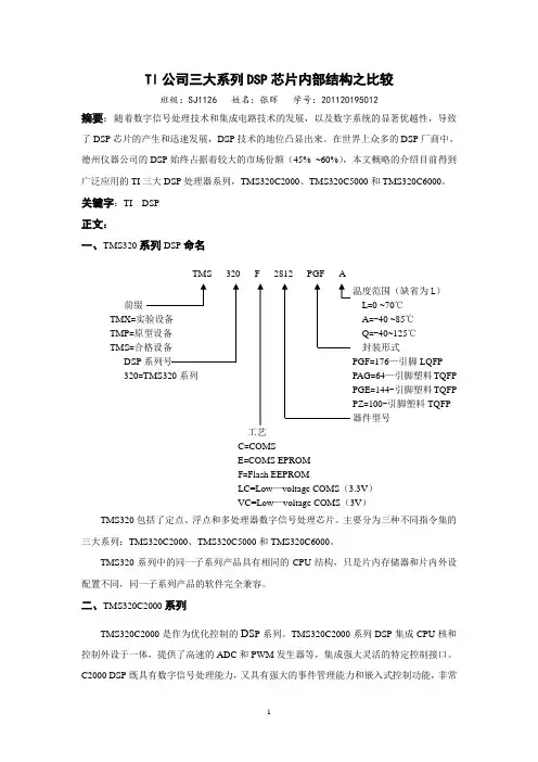
关键字:TI DSP正文:一、TMS320系列DSP命名TMS 320 F 2812 PGF A温度范围(缺省为L)前缀L=0 ~70℃TMX=A=-40 ~85℃TMP=Q=-40~125℃TMS=封装形式DSP PGF=176—引脚LQFP320=TMS320系列PAG=64—引脚塑料TQFPPGE=144-引脚塑料TQFPPZ=100-引脚塑料TQFP器件型号工艺C=COMSE=COMS EPROMF=Flash EEPROMLC=Low—voltage COMS(3.3V)VC=Low—voltage COMS(3V)TMS320包括了定点、浮点和多处理器数字信号处理芯片。
主要分为三种不同指令集的三大系列:TMS320C2000、TMS320C5000和TMS320C6000。
TMS320系列中的同一子系列产品具有相同的CPU结构,只是片内存储器和片内外设配置不同,同一子系列产品的软件完全兼容。
二、TMS320C2000系列TMS320C2000是作为优化控制的DS P系列。
TMS320C2000系列DSP集成CPU核和控制外设于一体,提供了高速的ADC和PWM发生器等,集成强大灵活的特定控制接口。
C2000 DSP既具有数字信号处理能力,又具有强大的事件管理能力和嵌入式控制功能,非常实用于工业、汽车、医疗和消费类市场中数字电机控制、数字电源和高级感应技术。
第三章DSP芯片系统实验实验3.1 :数据存取实验一.实验目的1.了解TMS320F2812A的内部存储器空间的分配及指令寻址方式。
2.了解ICETEK-F2812-A评估板扩展存储器空间寻址方法,及其应用。
3.了解ICETEK-F2812-EDU实验箱扩展存储器空间寻址方法,及其应用。
4.学习用Code Composer Studio修改、填充DSP内存单元的方法。
5.学习操作TMS32028xx内存空间的指令。
二.实验设备计算机,ICETEK-F2812-A-EDU实验箱(或ICETEK仿真器+ICETEK-F2812-A评估板+相关连线及电源)。
三.实验内容在外部SARAM的0x80000~0x8000f单元置数0~0xf,将该单元块存储的数据复制到0x80100~0x8010f处,最后通过“Memory”查看窗口观察各存储区中的数据。
四.实验原理TMS32028xx DSP内部存储器资源介绍:TMS32028xx系列DSP基于增强的哈佛结构,可以通过三组并行总线访问多个存储空间。
它们分别是:程序地址总线(PAB)、数据读地址总线(DRAB)和数据写地址总线(DW AB)。
由于总线工作是独立的,所以可以同时访问程序和数据空间。
TMS32028xx系列DSP的地址映象请参考第一章1.2.4节ICETEK-F2812-A评估板的存储空间定义及寄存器映射说明中的介绍。
五.实验步骤1.实验准备连接实验设备。
参见第一章1.3.1节中的“硬件连接方法”。
连接仿真器USB口接线,打开实验箱电源开关,接通评估板电源(关闭实验箱上的扩展模块和信号源电源开关)。
2.设置Code Composer Studio 2.21在硬件仿真(Emulator)方式下运行。
参见第一章1.4.2节中的“设置CCS工作在硬件仿真环境”。
3.启动Code Composer Studio 2.21选择菜单Debug→Reset CPU。
D S P -F 2812-S P I -F I F O 调试总结2010-5-231、调试运行期间,不可间断,哪怕是用刷新一下寄存器的值也不可以。
因为,SP I的运行是以时钟为基准的,即便是很短暂的延时或是外界干扰,也可能导致数据不正确。
而你如果刷新一下寄存器,在实时调试期间,无论程序运行在何处,都会有很短暂的延时,对D S P 来说,不能忽略!2、如果想查看通信传输的结果是否正确,只需运行一段时间,停止,查看事先设置好的暂存数据的数组即可。
3、下面的例程调试时,是将从机烧写到另一块D S P 的F L A S H 里面,主机采用实时调试方式。
4、把从机程序写到f l a s h时要注意:一定要在R A M区初始化F L A S H ,只有这样,其代码的运行速度才可以达到一个相对来说比较高的水平。
5、像这种反复进出中断的程序,在时序上的确让人很头疼,在中断里有时即便有很短暂的延时,也会出现错误,或者是刚开始运行正常,可过不了多久,传输数据就会出现差错。
6、主机的程序如下,从机的几乎是一样的,只是把主从设置为改了即可。
#i n c l u d e " D S P 281x _D e v i c e . h "#i n c l u d e " D S P 281x _E x a m p l e s . h "#d e f i n e G p i o S e l e c t ( E A L L O W ; \G p i o M u x R e g s . G P F M U X . a l l = 0x 000F ; \ E D I Si n t e r r u p t v o i d S p i T x I s r (v o i d ;i n t e r r u p t v o i d S p i R x I s r (v o i d ;v o i d I n i t S p i F I F O (v o i d ;v o i d E r r o r ( ;u n s i g n e d i n t i = 0, r d a t a [8], s d a t a [8];v o i d m a i n (v o i d{I n i t S y s C t r l ( ; //初始化系统时钟G p i o S e l e c t ( ; //初始化G P I O ,配置本例程需要G P I O 端口 D I N T ; //关C P U 级总中断I E R = 0x 0; //关P I E 级所有中断I F R = 0x 0;I n i t P i e C t r l ( ; //初始化P I E 控制寄存器I n i t P i e V e c t T a b l e ( ; //将P I E 中断向量表重新映射到特定位置,使能P I E 级中断E A L L O W ;P i e V e c t T a b l e . S P I R X I N T A = &S p i R x I s r ; //指定中断服务子程序的入口地址P i e V e c t T a b l e . S P I T X I N T A = &S p i T x I s r ;E D I S ;P i e C t r l R e g s . P I E I E R 6. b i t . I N T x 1 = 1; //使能P I E 级的S P I R X I N T 中断P i e C t r l R e g s . P I E I E R 6. b i t . I N T x 2 = 1;I E R |= M _I N T 6; //使能第六组P I E 级中断E I N T ; //开放C P U 级中断E R T M ; //使能实时调试中断P i e C t r l R e g s . P I E A C K . a l l = P I E A C K _G R O U P 6; //允许接受该组的中断请求I n i t S p i F I F O ( ; //初始化S P I , 配置成所需模式D E L A Y _U S (1 ;f o r (; ; ; //等待中断}v o i d I n i t S p i F I F O (v o i d{S p i a R e g s . S P I C C R . a l l = 0x 000F ; //S P I配置寄存器,复位、禁止自测模式、下降沿发送数据、字符长度为16 S p i a R e g s . S P I C T L . a l l = 0x 000E ; //S P I操作寄存器,为主机模式、yo u 延时、主机、允许发送S p i a R e g s . S P I B R R = 124; //S P I波特率寄存器,300K H zS p i a R e g s . S P I F F T X . a l l = 0x c 028; //复位、使能F I F O模式、使能T X 匹配中断、8级中断匹配 S p i a R e g s . S P I F F R X . a l l = 0x 0028; //复位、使能R X 匹配中断、8级响应中断S p i a R e g s . S P I F F C T . a l l = 0x 0; //无延时S p i a R e g s . S P I F F R X . b i t . R X F I F O R E S E T = 1; //退出复位 S p i a R e g s . S P I F F T X . b i t . T X F I F O = 1;S p i a R e g s . S P I C C R . b i t . S P I S W R E S E T = 1;}i n t e r r u p t v o i d S p i T x I s r (v o i d{f o r (i =0; i <8; i ++{s d a t a [i ] = i +1; //初始化发送数据S p i a R e g s . S P I T X B U F = s d a t a [i ];}S p i a R e g s . S P I F F T X . b i t . T X F F I N T C L R = 1; //清除发送中断,已可以响应其他中断P i e C t r l R e g s . P I E A C K . a l l = P I E A C K _G R O U P 6; //允许响应该组其他的中断}i n t e r r u p t v o i d S p i R x I s r (v o i d{注丗发送级别最好设为0否则可能出现意向不到的问题f o r (i =0; i <8; i ++{r d a t a [i ] = S p i a R e g s . S P I R X B U F ;i f (r d a t a [i ] == 0 i = 0; //舍去伪数据,实验时发现刚开始收的数据都是0,在此姑且这么认为i f (r d a t a [i ] ! = s d a t a [i ] E r r o r ( ; //收发数据不相等,报错,停止}S p i a R e g s . S P I F F R X . b i t . R X F F I N T C L R = 1; //清除接受中断 P i e C t r l R e g s . P I E A C K . a l l = P I E A C K _G R O U P 6;}v o i d E r r o r (v o i d{a s m (" E S T O P 0" ; //错误,则调试终止f o r (; ; ;}。
编号南京航空航天大学毕业论文题目基于MCBSP的多通道高精度D/A转换实现学生姓名吴田学号050810218学院机电学院专业机械工程及自动化班级0509102指导教师薛重德副教授二〇一三年六月南京航空航天大学本科毕业设计(论文)诚信承诺书本人郑重声明:所呈交的毕业设计(论文)(题目:)是本人在导师的指导下独立进行研究所取得的成果。
尽本人所知,除了毕业设计(论文)中特别加以标注引用的内容外,本毕业设计(论文)不包含任何其他个人或集体已经发表或撰写的成果作品。
作者签名:年月日(学号):基于McBSP的多通道高精度D/A转换实现摘要数字信号处理器(DSP)是针对数字信号处理需要而设计的一种可编程的单片机,有两大特色:强大数据处理能力和高运行速度。
DSP获得了越来越广泛的应用,学习DSP 有重要的现实意义。
本文主要是利用TMS320F2812 DSP的McBSP(多通道缓冲串行口)接口设计多通道高精度的D/A转换电路,并编程实现。
F2812是TI公司最新推出的DSP芯片,属于TMS320C2000系列。
F2812核心支持全新CCS环境的C 编译器,提供C 语言中直接嵌入汇编语言的程开发界面,可在C 语言的环境中搭配汇编语言来撰写程序。
利用自主设计的32位TMS320F2812 DSP 开发板开展工作,F2812 DSP本身不带D/A转换器,其中要使用MCBSP实现SPI协议,编写通过McBSP接口对D/A转换器进行操控程序,通过DSP采集信号发送给DAC,启动DAC实现DA转换,所使用的DAC为DAC8568,它有8个DAC通道,从而实现多路D/A同步或异步高精度转换。
关键词:SPI,MCBSP,DAC8568,多通道,高精度,D/A转换Based on McBSP multi-channel high-precision D / A converter to achieveAbstractDigital signal processor (DSP) for digital signal processing requires the design of a programmable microcontroller, there are two features: powerful data processing capability and high speed. DSP gained more and more widely, learning DSP has important practical significance.In this paper, the use of TMS320F2812 DSP McBSP (multichannel buffered serial port) interface design high-precision multi-channel D / A converter circuit and programming.F2812 is TI's latest DSP chip, belonging TMS320C2000 series. F2812 core supports the new CCS C compiler environment, provides a C language embedded directly in assembly language interface, process development, in an environment with C language to write assembly language program.The use of self-designed 32 TMS320F2812 DSP development board to work, F2812 DSP itself, without D / A converters, which use MCBSP to implement the SPI protocol, prepared through McBSP interface for D / A converter control procedures, through the DSP signal acquisition send to a DAC, DAC started to achieve DA conversion, as used in DAC DAC8568, which has eight DAC channels, enabling multi-channel D / A conversion precision synchronous or asynchronous.Key Words:SPI; MCBSP; dac ;Multi-channel;High-precision D / A converter目录摘要 (i)Abstract .............................................................................................................................................................. i i 目录 ................................................................................................................................................................... i ii 第一章引言 ................................................................................................................................................... - 1 -1.1论文研究背景 .................................................................................................................................... - 1 -1.2 主要方法及意义 ............................................................................................................................... - 1 -1.3主要工作 ............................................................................................................................................ - 1 -第二章 TMS320F2812 DSP控制板的简单介绍 .......................................................................................... - 3 -2.1 数字信号处理与DSP器件 ............................................................................................................... - 3 -2.2 TMS320F2812性能概述 .................................................................................................................... - 4 -第三章MCBSP ................................................................................................................................................ - 6 -3.1 McBSP简介 ........................................................................................................................................ - 6 -3.2 TMS320F281212的MCBSP ................................................................................................................. - 6 -3.3 用MCBSP实现SPI协议 ................................................................................................................... - 8 -3.31 SPI协议 ...................................................................................................................................... - 8 -3.32 SPI协议实现方法 ...................................................................................................................... - 8 -3.33 MCBSP实现SPI协议 ................................................................................................................. - 9 -3.34 MCBSP作为SPI的相关配置 .................................................................................................... - 10 -3.4 MCBSP串口寄存器 .......................................................................................................................... - 11 -3.41串口控制寄存器1的详细说明(SPCR1) .............................................................................. - 11 -3.42 串口控制寄存器2的详细说明(SPCR2 ) ........................................................................... - 12 -3.5串口的接收控制 .............................................................................................................................. - 13 -3.51接收控制寄存器1(RCR1)说明 ............................................................................................. - 13 -3.52接收控制寄存器2(RCR2)说明 ............................................................................................. - 13 -3.6串口的发送控制 .............................................................................................................................. - 13 -3.61发送控制寄存器1(XCR1)说明 ............................................................................................. - 13 -3.62发送控制寄存器2(XCR2)说明 ............................................................................................. - 14 -3.7采样率发生器及采样率发生控制器寄存器 .................................................................................. - 14 -3.71采样率发生器 ............................................................................................................................ - 14 -3.72采样率发生器控制寄存器(SRGR1/2) .................................................................................. - 15 -第四章DAC8568 .......................................................................................................................................... - 16 -4.1 dac8568的简单介绍 ...................................................................................................................... - 16 -4.2 DAC8568 DA转换原理 .................................................................................................................... - 20 -4.3串行接口 .......................................................................................................................................... - 21 -4.4输入移位寄存器 .............................................................................................................................. - 22 -第五章设计及编程 ................................................................................................................................... - 23 -5.1 CCS的简单介绍 .............................................................................................................................. - 23 -5.2建立一个完整的CCS工程 .............................................................................................................. - 24 -5.3接口电路的设计 .............................................................................................................................. - 25 -5.4软件实现 .......................................................................................................................................... - 26 -第六章总结和展望 ................................................................................................................................... - 27 -参考文献 ..................................................................................................................................................... - 28 -致谢 ............................................................................................................................................................. - 29 -附录 ............................................................................................................................................................. - 30 -第一章引言1.1论文研究背景数字信号处理(Digital Signal Processing,简称DSP)是一门涉及许多学科而又广泛应用于许多领域的新兴学科。
![TI C2000系列DSP Flash烧写解决方案 (Rev[1]. A)](https://uimg.taocdn.com/0ff2c881e53a580216fcfef5.webp)

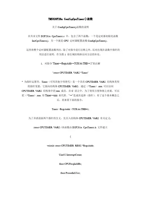
TMS320F28x ConfigCpuTimer()函数关于ConfigCpuTimer()函数的说明在共享文件DSP281x_CpuTimers.c 中,包含了两个函数:一个是定时器初始化函数InitCpuTimers(),另一个就是CPU 定时器配置函数ConfigCpuTimer()。
这里将整个定时器配置函数列出,除了对指令进行注释之外,还对出现在函数中指针的用法进行说明,作为第1 章位域结构体访问方法的补充。
1.对指令“Timer→RegsAddr→TCR.bit.TRB = 1”的注解"struct CPUTIMER_V ARS *Timer"* 为指针运算符,Timer(可用其他字母替代)是一个具有CPUTIMER_V ARS 结构体类型的指针变量,它指向结构体CPUTIMER_V ARS。
通过(*Timer).xxx 可以访问CPUTIMER_V ARS 结构体中的xxx 成员。
在C 语言中,为了使用方便和使之直观,可以把(*Timer).xxx 用Timer→xxx 来代替。
“→”是成员选择(指针)。
有了这个基本概念之后,再来看下面的指令:Timer->RegsAddr->TCR.bit.TRB=1;为了弄清前面两个指针的含义,先引入结构体CPUTIMER_V ARS 有关定义:struct CPUTIMER_V ARS //该函数由DSP281x_CpuTimers.h 文件建立{volatile struct CPUTIMER_REGS *RegsAddr;Uint32 InterruptCount;float CPUFreqInMHz;float PeriodInUSec;};这个结构体列出了CPU 定时器所支持的变量,其第一个成员是一个包含CPU 定时器所有专用寄存器的结构体(CPUTIMER_REGS),RegsAddr 是一个具有CPUTIMER_REGS 结构体类型的指针变量,其他3 个成员与定时器寄存器有联系,但不属于定时器专用寄存器。
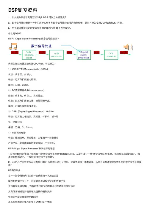
DSP复习资料1、什么是数字信号处理器(DSP)?DSP 可以分为哪两类?a、数字信号处理器是⼀种专门⽤于实现各种数字信号处理算法的微处理器,通常可分为专⽤DSP和通⽤DSP两类。
b、⽤于实现某些特定数字信号处理功能的DSP 属于专⽤DSP。
什么是DSP?DSP:Digtal Signal Processing 数字信号处理技术典型的微处理器系统根据CPU特点,可以分为:1)通⽤单⽚机(Micro-controller) 8/16bit优点:成本低、体积⼩。
缺点:运算与扩展能⼒较弱。
编程:汇编、C语⾔。
2)PC及其兼容机(Micro-processor)缺点:成本⾼、体积⼤、实时性差。
优点:运算与扩展能⼒强,软件资源丰富。
编程:汇编及多种⾼级语⾔。
3)DSP(Digital Signal Processor)16/32bit特点:运算能⼒相当强、实时性、体积⼩、成本较低、功耗较低编程:汇编、C、C++。
4)专⽤微处理器特点:使⽤简单,灵活性差,主要⽤于⼀些批量⽣产的产品。
如家⽤电器的智能控制、⼯业控制。
DSP: Digtal Signal Processor 数字信号处理器TI公司从80代初推出了全球第⼀款“数字信号处理器”TMS320C010,从此引发了⼀场“数字信号处理”⾰命。
我们现在所说的DSP,如果没有特殊说明,⼀般均指“数字信号处理器”。
2、DSP 芯⽚的主要特点有哪些?DSP 从结构上进⾏了优化,使其更适合于哪类运算,从⽽可以⾼速实现多种不同的数字信号处理算法?DSP的特点:在⼀个指令周期内可完成⼀次乘法和⼀次加法运算程序和数据空间分开,可以同时访问指令空间和数据空间⽚内具有快速RAM,通常可通过独⽴的数据总线在两块中同时访问具有低开销或⽆开销循环及跳转的硬件⽀持快速的中断处理和硬件I/O⽀持具有在单周期内操作的多个硬件地址产⽣器可以并⾏执⾏多个操作⽀持流⽔线操作,使取指令、译码、取操作数和执⾏指令等可以重叠执⾏。
DSP总结之(1)第一部分:TMS320F2812简介♦DSP(Digital Signal Processor)数字信号处理器,主要研究如何将理论上的数据处理技术应用于DSP中。
♦DSP采用哈佛结构,通过独立的数据总线在程序空间和数据空间同时访问。
♦在一个指令周期内(150MHz,6.67ns)可以完成一次乘法和一次加法运算。
♦TMS320F2812是TI(Texas Instruments)公司推出的32位定点DSP芯片,属于C2000系列。
向下是2407,向上是28335。
TMS表合格产品,320表TI DSP系列,F表Flash EEROM (内核电压1.8/1.9V,I/O口电压3.3V),PGF表176脚LQFP封装,A表40℃-85℃。
♦DSP开发所需准备的工具:CCS3.3+仿真器XDS100+目标板F2812+具体外围电路♦F2812片内外设(DSP内部集成的外部设备)6个:EV A EVB ADC SCIA SCIB SPI CAN McBSP♦常用地:脚86,常用3.3V:脚81♦用ADC时,脚175和176相连♦常用到F14作为I/O口输出,作指示使用♦JTAG(Joint Test Action Group ,联合测试行动小组) 是一种国际标准测试协议,主要用于芯片内部测试及对系统进行仿真、调试,如今大多数比较复杂的器件都支持JTAG 协议,如ARM 、DSP 、FPGA 器件等。
♦工程文件放在MyProjects文件夹中肯定好使,放在其他地方(桌面除外)亦可。
♦.h文件定义了DSP内部寄存器的数据结构、中断服务程序等内容软件开发时编写的代码都是写在.c中.cmd文件规定了把哪些代码放到哪个区域,管存储空间分配♦.h中宏定义、变量、函数声明.c所有变量和函数的定义♦DSP281x_Device.h中有一段代码已经包含了其他的头文件(具体多少个在其中看,2个未加DSP281x_Device.h)。
目录1.DSP学习步骤 (2)2.搞明白几个问题 (2)S6 创建新工程 (3)A.教程一 (3)B.教程二 (7)C.仿真环境构建 (13)4.TMS320F28x寄存器配置总结 (15)基本开局初始化 (15)1.时钟与系统控制 (16)2.中断控制PIE (21)3.GPIO (24)4.ADC (27)5.增强型脉宽调制器ePWM (29)6.HRPWM (32)7.SCI (36)8.SPI (40)9.CAN (42)10.CMD文件 (49)5.TMS320F28035 DEMO板实验 (51)1.GPIO 实验 (51)2.定时器中断实验 (52)3.PWM占空比调节 (53)4.ADC实验 (54)5.SPI实验 (56)6.SCI实验 (58)6.经验&教训 (63)读前须知:本人在此之前完全没接触过DSP,这是我学习过程中所做的笔记,直到最后能做些各个模块的一些简单配置实现简单的功能。
希望能给新手一些帮助,与君共勉!1.DSP学习步骤1.大体上看一遍书,把大体的知识了解一下。
在学习DSP之前,我觉得应该需要去明白DSP能干什么,所以你一定要看看DATASHEET,看看DSP的外设和资源,看看你能做啥.2.就是看例子了,例子是关键,例子里有你学的所有的东西,不建议大家直接拿例程来做试验,因为那样你MCU的结构没有把握,你把例程跑得再好,那也不是你的东西,一定要自己写,例程只能作为参照,一定要一个字母一个字母地去写程序.看例程,在自己编写自己需要功能的代码时要看看已有的例程,看看例程里的各种寄存器是怎么配置的,配置时又是怎么实现的,根据看懂的编写自己想要的,然后跑跑自己的程序看和已有的例程有什么异同,是不是自己想要的。
当然,调试环节是最难的一个环节,这个过程中会出现很多意想不到的问题,只能慢慢摸索慢慢前进了。
3.这次你再拿出一本书来看,这次是有针对性的看,比如你做的spi的,你就直接看spi那张,一边看例子一边看书,这样你就可以把一些重要的寄存器给记住了.4.把存储器映射结构搞清楚----说的具体点就是dsp内到底有那些存储器5.(ram,rom,flash,etc),这些存储器到底是如何分配的,这个可以参考相关的.cmd文件的写法,它定义了存储器映射和输入输出段的位置6.编译器的堆栈操作,就是中断或是子程序调用时,系统自己的堆栈操作。
TMS320x28xx,28xxx DSP Peripheral Reference GuideLiterature Number:SPRU566IJune2003–Revised May20092SPRU566I–June2003–Revised May2009Submit Documentation Feedback1Abbreviations (5)2Peripherals Available Per Device (7)3Peripheral Descriptions (10)3.1System Control and Interrupts (10)3.2External Interface(XINTF) (11)3.3Enhanced Controller Area Network(eCAN) (11)3.4Event Manager(EV) (12)3.5Analog Modules (12)3.6Multichannel Buffered Serial Port(McBSP) (13)3.7Serial Communications Interface(SCI) (13)3.8Serial Peripheral Interface(SPI) (14)3.9Boot ROM (14)3.10Inter-Integrated Circuit(I2C)Module (14)3.11Enhanced Quadrature Encoder Pulse(eQEP)Module (15)3.12Enhanced Capture(eCAP)Module (15)3.13Enhanced Pulse Width Modulator(ePWM)Module (16)3.14High-Resolution Pulse Width Modulator(HRPWM)Module (17)3.15Direct Memory Access(DMA) (18)3.16Local Interconnect Network(LIN) (18)3.17Control Law Accelerator(CLA) (18)Appendix A Revision History (19)A.1Changes Made in This Revision (19)SPRU566I–June2003–Revised May2009Table of Contents3 Submit Documentation FeedbackList of Tables1Abbreviation Matrix (5)2TMS320x281x Peripheral Selection Guide (7)3TMS320x280x,TMS320x2801x Peripheral Selection Guide (7)4TMS320x2804x Peripheral Selection Guide (8)5TMS320F2833x,TMS320F2823x Peripheral Selection Guide (8)6TMS320x2834x Peripheral Selection Guide (9)7TMS320F2802x Peripheral Selection Guide (9)8TMS320F2803x Peripheral Selection Guide (9)9External Interface(XINTF)Module Types (11)10Enhanced Controller Area Network(eCAN)Module Types (11)11Event Manager(EV)Module Types (12)12Analog Digital Controller(ADC)Module Types (12)13Comparator Module Types (13)14Multichannel Buffered Serial Port(McBSP)Module Types (13)15Serial Communications Interface(SCI)Module Type (13)16Serial Peripheral Interface(SPI)Module Type Description (14)17Inter-Integrated Circuit(I2C)Module Type Description (15)18Enhanced Quadrature Encoder Pulse(eQEP)Module Type Description (15)19Enhanced Capture(eCAP)Module Types (16)20Enhanced Pulse Width Modulator(ePWM)Module Types (17)21High-Resolution Pulse Width Modulator(HRPWM)Module Types (17)22Direct Memory Access(DMA)Module Types (18)23Local Interconnect Network(LIN)Module Types (18)24Control Law Accelerator(CLA)Module Types (18)List of Tables4SPRU566I–June2003–Revised May2009Submit Documentation Feedback1AbbreviationsReference GuideSPRU566I–June 2003–Revised May 2009This overview guide describes all the peripherals available for TMS320x28xx and TMS320x28xxx devices.Section 2shows the peripherals used by each device.Section 3provides descriptions of the peripherals.the peripheral guide by clicking on number,which is linked to the portable document format (pdf)file.Throughout this document and other peripheral guides,the following abbreviations are used for a series of 28x microcontrollers:•TMS320x28xx refers to TMS320x281x and TMS320x280x devices•TMS320x28xxx refers to TMS320x2801x,TMS320x2804x,TMS320x2833x,TMS320x2834x,TMS320x2802x,and TMS320x2803x devices.Specific device abbreviations are listed in Table 1.Table 1.Abbreviation MatrixDevice AbbreviationGroup Family Device (1)UsedAbbreviationTMS320x281xTMS320F2810,TMS320C2810,SM320F2810-EP (2)2810281xTMS320F2811,TMS320C2811,TMS320R2811,SM320F2811-EP (2)2811TMS320F2812,TMS320C2812,TMS320R2812,SM320F2812-EP (2)2812TMS320x280xTMS320F2801,TMS320C28012801280xTMS320F2802,TMS320C28022802TMS320F28062806TMS320F2808,SM320F2808-EP (2)2808TMS320F28092809TMS320x2801x TMS320F28015280152801x TMS320F2801628016TMS320x2804x TMS320F28044280442804x TMS320F2833xTMS320F28335283352833xTMS320F2833428334TMS320F2833228332TMS320F2823xTMS320F28235282352823xTMS320F2823428234TMS320F2823228232(1)Where F precedes the device abbreviation,it stands for Flash memory;C stands for RAM.(2)Military device that may be abbreviated differently elsewhere;the abbreviations shown are relevant to this document and peripheral selection itary devices in this document all begin with a prefix of SM.SPRU566I–June 2003–Revised May 200928x DSP Peripherals 5Submit Documentation FeedbackAbbreviations Table1.Abbreviation Matrix(continued)Device Abbreviation Group Family Device(1)Used Abbreviation TMS320x2834x TMS320C28346283462834xTMS320C2834528345TMS320C2834428344TMS320C2834328343TMS320C2834228342TMS320C2834128342TMS320x2802x TMS320F28020280202802xTMS320F2802128021TMS320F2802228022TMS320F2802328023TMS320F2802628026TMS320F2802728027TMS320x2803x TMS320F28035280352803xTMS320F2803428034TMS320F2803328033TMS320F2803228032 28x DSP Peripherals6SPRU566I–June2003–Revised May2009Submit Documentation Feedback Peripherals Available Per Device 2Peripherals Available Per DeviceTable2through Table7show the peripherals that are available for each of the28xx,28xxx devices.Theto the document that can be downloaded.Table2.TMS320x281x Peripheral Selection Guide(1)TMS320x281x External Interface(XINTF)0XTMS320x281x Enhanced Controller Area Network(eCAN)0X XTMS320x281x Event Manager(EV)0X XTMS320x281x Analog-to-Digital Converter(ADC)0X XTMS320x281x Multichannel Buffered Serial Port(McBSP)0X XTMS320x281x Serial Communications Interface(SCI)0X XTMS320x281x Serial Peripheral Interface(SPI)0X X(1)A type change represents a major functional feature difference in a peripheral module.Within a peripheral type,there may beminor differences between devices which do not affect the basic functionality of the module.These device-specific differencesare listed in Section3and in the peripheral reference guides.Table3.TMS320x280x,TMS320x2801x Peripheral Selection Guide Peripheral Lit.No.Type(1)280128016280152802,2806,2808,2809 TMS320x280x,2801x,2804x System Control and Interrupts-X X XTMS320x280x,2801x DSP Enhanced Controller Area Network(eCAN)0X XUser's GuideTMS320x280x,2801x,2804x Analog-to-Digital Converter(ADC)1X X XTMS320x280x,2801x,2804x Serial Communications Interface(SCI)0X X XTMS320x280x,2801x,2804x Serial Peripheral Interface(SPI)0X X XTMS320x280x,2801x,2804x Boot ROM-X X XTMS320x280x,2801x,2804x Enhanced Quadrature Encoder Pulse0X(eQEP)TMS320x280x,2801x,2804x Enhanced Pulse Width Modulator0X X XModule(ePWM)TMS320x280x,2801x,2804x Enhanced Capture(eCAP)Module0X X XTMS320x280x,2801x,2804x Inter-Integrated Circuit(I2C)0X X XTMS320x280x,2801x,2804x High-Resolution Pulse-Width Modulator0X X X(HRPWM)(1)A type change represents a major functional feature difference in a peripheral module.Within a peripheral type,there may beminor differences between devices which do not affect the basic functionality of the module.These device-specific differencesare listed in Section3and in the peripheral reference guides.SPRU566I–June2003–Revised May200928x DSP Peripherals7 Submit Documentation FeedbackPeripherals Available Per Device Table4.TMS320x2804x Peripheral Selection Guide(1)TMS320x280x,2801x,2804x Analog-to-Digital Converter(ADC)1XTMS320x280x,2801x,2804x Serial Communications Interface(SCI)0XTMS320x280x,2801x,2804x Serial Peripheral Interface(SPI)0XTMS320x280x,2801x,2804x Boot ROM-XTMS320x280x,2801x,2804x Enhanced Pulse Width Modulator Module(ePWM)0XTMS320x280x,2801x,2804x Inter-Integrated Circuit(I2C)0Xminor differences between devices which do not affect the basic functionality of the module.These device-specific differencesare listed in Section3and in the peripheral reference guides.Table5.TMS320F2833x,TMS320F2823x Peripheral Selection Guide Peripheral Lit.No.Type(1)28335,28334,28332,28235,28234,28232 TMS320F2833x,2823x System Control and Interrupts-XTMS320F2833x,2823x External Interface(XINTF)1XTMS320F2833x,2823x Enhanced Controller Area Network(eCAN)0XTMS320F2833x,2823x Analog-to-Digital Converter(ADC)2XTMS320F2833x,2823x Multichannel Buffered Serial Port(McBSP)1XTMS320F2833x,2823x Serial Communications Interface(SCI)0XTMS320F2833x,2823x Serial Peripheral Interface(SPI)0XTMS320F2833x,2823x Boot ROM-XTMS320F2833x,2823x Enhanced Quadrature Encoder Pulse(eQEP)0XTMS320F2833x,2823x Enhanced Pulse Width Modulator Module(ePWM)0XTMS320F2833x,2823x Enhanced Capture(eCAP)Module0XTMS320F2833x,2823x Inter-Integrated Circuit(I2C)0XTMS320F2833x,2823x High-Resolution Pulse-Width Modulator(HRPWM)0Xminor differences between devices which do not affect the basic functionality of the module.These device-specific differencesare listed in Section3and in the peripheral reference guides.28x DSP Peripherals8SPRU566I–June2003–Revised May2009Submit Documentation Feedback Peripherals Available Per DeviceTable6.TMS320x2834x Peripheral Selection GuidePERIPHERAL GUIDE Lit.No.TYPE(1)28346,28345,28344,28343,TMS320x2834x Delfino External Interface(XINTF)1XTMS320x2834x Delfino Enhanced Controller Area Network(eCAN)0XTMS320x2834x Delfino Multichannel Buffered Serial Port(McBSP)1XTMS320x2834x Delfino Serial Communications Interface(SCI)0XTMS320x2834x Delfino Serial Peripheral Interface(SPI)0XTMS320x2834x Delfino Boot ROM-XTMS320x2834x Delfino Enhanced Quadrature Encoder Pulse(eQEP)0XTMS320x2834x Delfino Enhanced Pulse Width Modulator Module(ePWM)0XTMS320x2834x Delfino Enhanced Capture(eCAP)Module0XTMS320x2834x Delfino Inter-Integrated Circuit(I2C)0XTMS320x2834x Delfino High-Resolution Pulse-Width Modulator(HRPWM)0Xminor differences between devices that do not affect the basic functionality of the module.These device-specific differences are listed in Section3and in the peripheral reference guides.Table7.TMS320F2802x Peripheral Selection GuidePeripheral Lit.No.Type(1)28027,28021,28026,2802028023,28022 TMS320x2802x Piccolo System Control and Interrupts-X XTMS320x2802x,2803x Piccolo Analog-to-Digital Converter(ADC)and Comparator3/0(2)X XTMS320x2802x,2803x Piccolo Serial Communications Interface(SCI)0X XTMS320x2802x,2803x Piccolo Serial Peripheral Interface(SPI)1X XTMS320x2802x Piccolo Boot ROM-X XTMS320x2802x,2803x Piccolo Enhanced Pulse Width Modulator Module(ePWM)1X XTMS320x2802x,2803x Piccolo Enhanced Capture Module(eCAP)0X XTMS320x2802x,2803x Piccolo Inter-Integrated Circuit(I2C)0X Xminor differences between devices that do not affect the basic functionality of the module.These device-specific differences are listed in Section3and in the peripheral reference guides.(2)The is Type3and the comparator module is Type0.See Section3.5for more details.Table8.TMS320F2803x Peripheral Selection GuidePeripheral Lit.No.Type(1)28035,28034,2803328032 TMS320x2803x Piccolo System Control and Interrupts-x xTMS320x2803x Piccolo Enhanced Controller Area Network(eCAN)0x xTMS320x2802x,2803x Piccolo Analog-to-Digital Converter(ADC)and Comparator3/0(2)x xTMS320x2802x,2803x Piccolo Serial Communications Interface(SCI)0x xTMS320x2802x,2803x Serial Peripheral Interface(SPI)1x xTMS320x2803x Piccolo Boot ROM-x x(1)A type change represents a major functional feature difference in a peripheral module.Within a peripheral type,there may beminor differences between devices that do not affect the basic functionality of the module.These device-specific differences are listed in the peripheral reference guides.(2)The ADC module is Type3and the comparator module is Type0.SPRU566I–June2003–Revised May200928x DSP Peripherals9 Submit Documentation Feedback3Peripheral Descriptions3.1System Control and InterruptsPeripheral Descriptions Table 8.TMS320F2803x Peripheral Selection Guide (continued)PeripheralLit.No.Type (1)28035,28034,TMS320x2802x,2803x Piccolo Enhanced Capture Module (eCAP)0x x TMS320x2802x,2803x Piccolo Inter-Integrated Circuit (I2C)0x x TMS320x2802x,2803x High-Resolution Pulse-Width Modulator (HRPWM)1x xTMS320x2803x Piccolo Control Law Accelerator (CLA)0x Brief descriptions of the peripherals are included in the following sections.The device-specific guides are:•TMS320x281x System Control and Interrupts Reference Guide •TMS320x280x,2801x,and 2804x System Control and Interrupts Reference Guide •TMS320x2833x System Control and Interrupts Reference Guide •TMS320x2834x Delfino System Control and Interrupts Reference Guide •TMS320x2802x Piccolo System Control and Interrupts Reference Guide •TMS320x2803x Piccolo System Control and Interrupts Reference Guide These guides include information on the following modules:•Memory,including Flash and OTP configuration •Code security module (CSM)Security is defined with respect to the access of the on-chip program memory and prevents unauthorized copying of proprietary code.The code security module (CSM)blocks access to several on-chip program memory blocks.•Clocking and Low-Power ModesThe clocks to each individual peripheral can be enabled/disabled so as to reduce power consumption when a peripheral is not in use.Additionally,the system clock to the serial ports and the event managers,CAP and QEP blocks can be scaled relative to the CPU clock.This enables the timing of peripherals to be decoupled from increasing CPU clock speeds.•32-bit CPU-TimersCPU-Timers 0,1,and 2are identical 32-bit timers with presettable periods and with 16-bit clock prescaling.The timers have a 32-bit count down register,which generates an interrupt when the counter reaches zero.The counter is decremented at the CPU clock speed divided by the prescale value setting.When the counter reaches zero,it is automatically reloaded with a 32-bit period value.CPU-Timers 1and 2are reserved for Real-Time OS (RTOS)applications.CPU-Timer 2is connected to INT14of the CPU.CPU-Timer 1can be connected to INT13of the CPU.CPU-Timer 0is for general use and is connected to the PIE block.•Watchdog TimerThe 28x devices support a watchdog timer.The user software must regularly reset the watchdog counter within a certain time frame;otherwise,the watchdog generates a reset to the processor.The watchdog can be disabled if necessary.•General-purpose inputs/outputs (GPIO)Most of the peripheral signals are multiplexed with general-purpose I/O (GPIO)signals.This enables you to use a pin as GPIO if the peripheral signal or function is not used.On reset,all GPIO pins are configured as inputs.You can then individually program each pin for GPIO mode or peripheral signal mode.For specific inputs,you can also select the number of input qualification cycles to filter unwanted noise glitches.1028x DSP PeripheralsSPRU566I–June 2003–Revised May 2009Submit Documentation Feedback3.2External Interface (XINTF)3.3Enhanced Controller Area Network (eCAN) Peripheral Descriptions•Peripheral framesThe 28x devices contain three peripheral register spaces.Some registers within these frames can be protected from CPU writes by the EALLOW protection mechanism.•Peripheral interrupt expansion (PIE)The PIE block multiplexes numerous interrupt sources into a smaller set of interrupt inputs.The interrupts are grouped into blocks of eight and each group is fed into one of 12CPU interrupt lines (INT1to INT12).Each of the 96interrupts is supported by its own vector stored in a dedicated RAM block that can be overwritten by the user.The vector is automatically fetched by the CPU on servicing the interrupt.It takes nine CPU clock cycles to fetch the vector and save critical CPU registers.Therefore,the CPU can respond quickly to interrupt events.Prioritization of interrupts is controlled in hardware and software.Each individual interrupt can be enabled/disabled within the PIE block.•External InterruptsThe XINTF guides are:•TMS320x281x External Interface (XINTF)Reference Guide•TMS320F2833x,2823xExternal Interface (XINTF)Reference Guide •TMS320x2834x Delfino External Interface (XINTF)Reference Guide The external interface (XINTF)is an asynchronous bus that is used to interface to external devices and memory.Table 9lists the differences between XINTF types,including device-specific differences within each type.Table 9.External Interface (XINTF)Module TypesType DescriptionDevices Covered Device-Specific Options0External Interface with x16Data Bus2810,2811,2812-1External Interface with x16or x32Data Bus 28335,28334,28332,28235,28234,-28232,28346,28345,28344,28343,28342,28341This is the enhanced version of the CAN peripheral.It supports 32mailboxes,time stamping of messages,and is CAN 2.0B-compliant.The eCAN guides are:•TMS320x281x DSP Enhanced Controller Area Network (eCAN)Reference Guide •TMS320x280x,2801x DSP Enhanced Controller Area Network (eCAN)Reference Guide •TMS320x2833x/2823x DSP Enhanced Controller Area Network (eCAN)Reference Guide •TMS320x2834x Delfino Enhanced Controller Area Network (eCAN)Reference Guide •TMS320x2803x Piccolo Enhanced Controller Area Network (eCAN)Reference Guide Table 10lists the differences between eCAN types,including device-specific differences within each type.Table 10.Enhanced Controller Area Network (eCAN)Module TypesModule DescriptionDevices CoveredDevice-Specific OptionsType 0Original eCAN Module Type2810,2811,2812,2801,2802,2806,2808,2809,CAN module clock =SYSCLK 2801628335,28334,28332,28235,28234,28232,CAN module clock =SYSCLK/228035,28034,28033,2803228346,28345,28344,28343,28342,28341CAN module clock =SYSCLK/4SPRU566I–June 2003–Revised May 200928x DSP Peripherals 11Submit Documentation Feedback3.4Event Manager (EV)3.5Analog Modules3.5.1Analog-to-Digital Converter (ADC)3.5.2Comparator Module (COMP)Peripheral Descriptions The event manager module includes general-purpose timers,full-compare/pulse-width modulation (PWM)units,capture inputs (CAP)and quadrature-encoder pulse (QEP)circuits.Two such event managers are provided,which enable two three-phase motors to be driven or four two-phase motors.The event managers on the F281x are compatible to the event managers on the 240x devices (with some minor enhancements).The EV guide is:•TMS320x281x Event Manager Reference GuideTable11lists the differences between EV types,including device-specific differences within each type.Table 11.Event Manager (EV)Module TypesType DescriptionDevices Covered Device-Specific Options 0Original EV Module Type2810,2811,2812-The analog-to-digital converter (ADC)module and comparator module descriptions are in this section.The device-specific ADC guides are:•TMS320x281x Analog-to-Digital Converter (ADC)Reference Guide •TMS320x280x 2801x,2804x Analog-to-Digital Converter (ADC)Module Reference Guide •TMS320x2833x,2823x Analog-to-Digital Controller (ADC)Module Reference Guide •2803x Piccolo Analog-to-Digital Converter (ADC)and Comparator Reference Guide The ADC block is a 12-bit converter,single ended,16-channels.It contains two sample-and-hold units for simultaneous sampling.Table 12lists the differences between ADC types,including device-specific differences within each type.Table 12.Analog Digital Controller (ADC)Module TypesType DescriptionDevices Covered Device-SpecificOptions0Original ADC Module Type2810,2811,2812–1Added Offset Trim and Reference Select registers 2801,2802,2806,2808,2809,28015,–28016,280442Added Internal/External Trim registers(OTP trim)28335,28334,28332,28235,28234,–282323Different control register interface,converts from 028027,28026,28023,28022,28021,–to 3.3V fixed scale range,supports ratiometric 28020,28035,28034,28033,28032VREFHI/VREFLO referencesThe device-specific comparator guides are:•2803x Piccolo Analog-to-Digital Converter (ADC)and Comparator Reference Guide The comparator module includes a 10-bit reference and can be routed to directly control ePWM outputs.Table 13lists the differences between comparator types,including device-specific differences within each 28x DSP Peripherals12SPRU566I–June 2003–Revised May 2009Submit Documentation Feedback3.6Multichannel Buffered Serial Port (McBSP)3.7Serial Communications Interface (SCI) Peripheral DescriptionsTable parator Module TypesType DescriptionDevices CoveredDevice-Specific OptionsOriginal Comparator Module Type28027,28026,28023,28022,28021,28020,–28035,28034,28033,28032The device-specific McBSP guides are:•TMS320x281x Multichannel Buffered Serial Port (McBSP)Reference Guide•TMS320x2833xMultichannel Buffered Serial Port (McBSP)Reference Guide •TMS320x2834x Delfino Multichannel Buffered Serial Port (McBSP)Reference Guide The McBSP is used to connect to E1/T1lines,phone-quality codecs for modem applications orhigh-quality stereo-quality Audio DAC devices.The McBSP receive and transmit registers are supported by a 16-level FIFO.This significantly reduces the overhead for servicing this peripheral.Table 14lists the differences between ADC types,including device-specific differences within each type.Table 14.Multichannel Buffered Serial Port (McBSP)Module TypesType DescriptionDevices Covered Device-SpecificOptions0Original McBSP Module Type2810,2811,2812-1Removed FIFO to allow interconnect with DMA module.28335,28334,28332,28235,-Removed FIFO-related registers (MFFTX,MFFRX,MFFCT,28234,28232,28346,28345,MFFST)28344,28343,28342,28341The SCI is a two-wire asynchronous serial port,commonly known as UART.The SCI supports a receive and transmit FIFO for reducing servicing overhead.The SCI guides are:•TMS320x281x Serial Communications Interface (SCI)Reference Guide •TMS320x280x,2801x,28044Serial Communications Interface (SCI)Reference Guide •TMS320x2833x,2823x Serial Communications Interface (SCI)Reference Guide •TMS320x2834x Delfino Serial Communications Interface (SCI)Reference Guide •TMS320x2802x,2803x Piccolo Serial Communications Interface (SCI)Reference Guide Table 15lists the differences between SCI types,including device-specific differences within each type.Table 15.Serial Communications Interface (SCI)Module TypeType DescriptionDevices CoveredDevice-Specific OptionsOriginal SCI Module Type2810,2811,2812,2801,2802,2806,2808,2809,16-level FIFO28015,28016,28044,28335,28334,28332,28235,28234,28232,28346,28345,28344,28343,28342,28341128027,28026,28023,28022,28021,28020,4-level FIFO28035,28034,28033,28032SPRU566I–June 2003–Revised May 200928x DSP Peripherals 13Submit Documentation Feedback3.8Serial Peripheral Interface (SPI)3.9Boot ROM3.10Inter-Integrated Circuit (I2C)ModulePeripheral Descriptions The SPI is a high-speed,synchronous serial I/O port that allows a serial bit stream of programmed length (one to sixteen bits)to be shifted into and out of the device at a programmable bit-transfer rate.Normally,the SPI is used for communications between the DSP controller and external peripherals or anotherprocessor.Typical applications include external I/O or peripheral expansion through devices such as shift registers,display drivers,and ADCs.Multi-device communications are supported by the master/slave operation of the SPI.The port supports a receive and transmit FIFO for reducing servicing overhead.The SPI guide is:•TMS320x281x Serial Peripheral Interface (SPI)Reference Guide•TMS320x280,2801x,2804xSerial PeripheralInterface(SPI)ReferenceGuide •TMS320x2833x,2823x Serial Peripheral Interface (SPI)Reference Guide •TMS320x2834x Delfino Serial Peripheral Interface (SPI)Reference Guide •TMS320x2802x,2803x Piccolo Serial Peripheral Interface (SPI)Reference Guide Table 16lists the differences between SPI types,including device-specific differences within each type.Table 16.Serial Peripheral Interface (SPI)Module Type DescriptionType DescriptionDevices CoveredDevice-Specific OptionsOriginal SPI Module Type2810,2811,2812,2801,2802,2806,2808,–2809,28015,28016,28044,28335,28334,28332,28235,28234,28232,28346,28345,28344,28343,28342,283411Added support for 3-wire28027,28026,28025,28024,28023,28022No STEINV bitbidirectional mode and reduced to 28035,28034,28033,28032Added STEINV bit (inverts 4-level FIFOSPISTE signal to support digital audio receive mode with 2SPIs)The device-specific Boot ROM guides are:•TMS320x281x Boot ROM Reference Guide •TMS320x280x,2801x,2804x DSP Boot ROM Reference Guide •TMS320x2833x,2823x Boot ROM Reference Guide •TMS320x2834x Delfino Boot ROM Reference Guide •TMS320x2802x Piccolo Boot ROM Reference Guide •TMS320x2803x Piccolo Boot ROM Reference Guide The boot ROM is factory-programmable with boot-loading software.Boot-mode signals (general-purpose I/Os)are used to tell the bootloader software which mode to use.The Boot ROM also contains standard math tables such as SIN/COS for use in IQ math related algorithms.The I2C guides include:•TMS320x280x,2801x,2804x Inter-Integrated Circuit (I2C)Module Reference Guide •TMS320x2833x,x2823x Inter-Integrated Circuit (I2C)Module Reference Guide •TMS320x2834x Delfino Inter-Integrated Circuit (I2C)Module Reference Guide •TMS320x2802x,2803x Piccolo Inter-Integrated Circuit (I2C)Module Reference Guide This guide describes the features and operation of the inter-integrated circuit (I2C)module.The I2C module provides an interface between one of these DSPs and devices compliant with PhilipsSemiconductors Inter-IC bus (I2C-bus)specification version 2.1and connected by way of an I2C-bus.External components attached to this 2-wire serial bus can transmit/receive 1-to 8-bit data to/from the DSP through the I2C module.This guide assumes the reader is familiar with the I2C-bus specification.1428x DSP PeripheralsSPRU566I–June 2003–Revised May 2009Submit Documentation Feedback3.11Enhanced Quadrature Encoder Pulse (eQEP)Module3.12Enhanced Capture (eCAP)Module Peripheral DescriptionsTable17liststhe differencesbetween I2Ctypes,includingdevice-specific differences within each type.Table 17.Inter-Integrated Circuit (I2C)Module Type DescriptionType DescriptionDevices CoveredDevice-Specific OptionsOriginal I2C Module Type2801,2802,2806,2808,2809,28015,28016,28044,16-level FIFO28335,28334,28332,28235,28234,28232,28346,28345,28344,28343,28342,2834128027,28026,28023,28022,28021,28020,28035,4-level FIFO28034,28033,28032The eQEP module guides include:•2801x,2804x Enhanced Quadrature Encoder Pule (eQEP)Module Reference Guide •2823x Enhanced Quadrature Encoder Pulse (eQEP)Module Reference Guide •Delfino Enhanced Quadrature Encoder Pulse (eQEP)Module Reference Guide •Piccolo Enhanced Quadrature Encoder Pulse (eQEP)Module Reference GuideThe enhanced quadrature encoder pulse (eQEP)module is used for direct interface with a linear or rotary incremental encoder to get position,direction,and speed information from a rotating machine for use in a high-performance motion and position-control system.Table 18lists the differences between eQEP types,including device-specific differences within each type.Table 18.Enhanced Quadrature Encoder Pulse (eQEP)Module Type DescriptionType DescriptionDevices CoveredDevice-Specific OptionsOriginal eQEP Module Type2801,2802,2806,2808,2809,28044,28335,-28334,28332,28235,28234,28232,28346,28345,28344,28343,28342,28341,28035,28034,28033,28032The eCAP guides are:•TMS320x280x,2801x,2804x Enhanced Capture (eCAP)Module Reference Guide •TMS320x2833x,2823x Enhanced Capture (eCAP)Module Reference Guide •TMS320x2834x Delfino Enhanced Capture (eCAP)Module Reference Guide •TMS320x2802x,2803x Piccolo Enhanced Capture (eCAP)Module Reference Guide The enhanced Capture (eCAP)Module is essential in systems where accurate timing of external events is important.Uses for eCAP include:•Speed measurements of rotating machinery (e.g.,toothed sprockets sensed via Hall sensors)•Elapsed time measurements between position sensor triggers •Period and duty cycle measurements of pulse train signals•Decoding current or voltage amplitude derived from duty cycle encoded current/voltage sensors Table 19lists the differences between eCAP types,including device-specific differences within each type.SPRU566I–June 2003–Revised May 200928x DSP Peripherals 15Submit Documentation Feedback。
基于TMS320F2812 flash搬移到RAM里运行实现去年在论坛上了“28335 学习系列__FLASH 搬移到RAM 运行实现方法”之后,很多网友提问有没有F2812 FLASH 搬移到RAM 运行实现方法。
其实,TI 28系列DSP目前用的很广泛的,关于FLASH搬移到RAM里运行文章也很多,但还有很多人不清楚如何实现,说明这些资料当中很多讲解的不够透彻,或者讲了很多,但没有告诉大家如何去做,如何去实现搬移。
很多附件里面的程序,大部分是没法运行的程序。
另外,对于初学DSP的人来说,搬移也是很令人费神的,往往调试半天一天的,程序就是不搬,然后就灰心丧气,然后就觉得DSP让人头疼。
其实,DSP作为一个工具,它不像我们学的很多专业理论知识。
有时候我们不能正常使用DSP,问题往往在于一些很细节的地方,或者是操作失误等等。
在写了一个“F28335 学习系列__FLASH 搬移到RAM 运行实现方法”,之后网友也收到了很多网友的回复。
回复中网友提出了很多问题,我将其归为3大类:第一:关于FLASH搬移到RAM运行的方法比较问题;第二:如何判断程序已经从FLASH搬移到RAM中;第三:如何实现F2812 FLASH搬移到RAM里运行;对于第一问题,实现FLASH搬移到RAM主要有两种方法,一种是部分搬移,另一种是全部搬移。
部分搬移即将程序代码中部分函数放到RAM中运行,使用这种搬移方法,主要是考虑到程序代码比较多,而DSP RAM空间有限,当全部搬移运行时,可能会产生数据空间调用冲突问题,反而降低了程序执行效率。
全部搬移即将程序中代码段,初始化段,常量段,变量定义段等等全部搬移到RAM中运行。
二者主要区别在于,前者在mian函数里面操作,通过MEMRYCOPY函数,在CMD中增加“ramfuncs”段,只要程序中放在“ramfuncs”里面便可实现搬移。
后者在CMD里实现搬移配臵,将“.cinit ,.const,.econst,.pinit ,.switch,.text”全部配臵成搬移。
一、填空题第一章1.数字信号处理特点大量的实时计算(FIR、IIR、FFT),数据具有高度重复(乘积和操作在滤波、卷积和FFT中等常见)。
2.信号处理的作用信号改善、信号检测、估计等。
3.信号处理的方法信号波形分析/变换、滤波、现代谱估计/分析、自适应滤波等。
4.信息系统包括采集、传输、处理等。
5.数字信号处理常用算法有FIR滤波、IIR滤波、离散傅里叶变换、卷积等。
6.处理器速度的提高得益于器件水平、处理器结构、并行技术等。
7.DSP结构特点包括哈弗结构、流水线技术、硬件乘法器、多处理单元、特殊的DSP指令。
8.DSP芯片按用途分为通用型DSP 、专用型DSP 。
9.DSP芯片按数据格式分为浮点型、定点型。
第二章1.C28x芯片具有C27x目标-兼容模式、C28x 模式、C2xLP源-兼容模式。
2.C28x芯片模式选择由ST1 中的OBJMODE 和AMODE 位组合来选定模式。
3.CPU内核由CPU 、仿真逻辑、接口组成。
4.CPU主要特性是、、、、。
5.CPU信号包括存储器接口信号、时钟和控制信号、复位和中断信号仿真信号。
6.TMS320F2812组成特点是32位、定点、改进哈佛结构、循环的寻址方式。
7.存储器接口有 3 组地址总线。
8.存储器接口有 3 组数据总线。
9.存储器接口地址总线有PAB 、DRAB 、DWAB 。
9.存储器接口数据总线有PRDB 、DRDB 、DWDB 。
10.CPU中断控制寄存器有IFR 、IER 、DBGIER 。
11.ACC累加器是32 位的,可表示为ACC 、AH 、AL 。
12.被乘数寄存器是32 位的,可表示为XT 、T 、TL 。
13.乘数结果寄存器是32 位的,可表示为P 、PH 、PL 。
14.数据页指针寄存器16 位的,有65536页,每页有64 存储单元。
数据存储空间容量是4M字。
15.堆栈指针复位后SP指向地址是0x000400h 。
第三章1.DSP芯片内部包含存储器类型有、、、、。
第2章 TMS320F281x DSP控制器总体结构 本章主要内容:Ø DSP引脚及其功能(Pins and Their Function of the DSP)Ø DSP的片内硬件资源(DSP On-chip Hardware Resources)Ø 存储器扩展外部接口XINTF(External Interface for Memory Extension)Ø DSP片内Flash和OTP存储器(DSP On-Chip Flash and OTP Memory)Ø 代码安全模块CSM(Code Security Module)Ø 时钟与低功耗模式(Clock and Low Power Modes)Ø 看门狗定时器(Watchdog Timer, WDT)Ø 32位CPU定时器(32-bit CPU Timers)Ø 通用输入/输出GPIO(General Purpose Input/Output)Ø 片内外设寄存器(On-chip Peripheral Registers)Ø 外设中断扩展PIE(Peripheral Interrupt Extension)2.1 DSP引脚及其功能图2-1为TMS320F2812的176引脚PGF LQFP(Low-Profile Quad Flatpack)封装图。
图2-2为TMS320F2810的128引脚PBK LQFP封装图。
还有一种为179引脚GHH球形网格阵列(Ball Grid Array, BGA)封装。
图2-1 TMS320F2812 的176引脚PGF LQFP封装图图2-2 TMS320F2810 的128引脚PBK LQFP封装图这些引脚按功能分类如下:(1) XINTF (External Interface)信号: 地址(19位)/数据(16位)/及存储器控制信号引脚。
(2) JTAG仿真测试及其他(振荡器、复位)引脚。
(3) A/D转换器引脚。
(4) 电源引脚。
(5) GPIOA、GPIOD或事件管理器A(EVA)引脚。
(6) GPIOB 、GPIOD或事件管理器B(EVB)引脚。
(7) 通信模块(SPI/SCI/CAN/McBSP)或GPIOF、GPIOG引脚。
(8) 外部中断或GPIOE引脚。
(9) 通用数字I/O GPIOF或XF输出引脚。
表2-1为F281x DSP引脚定义与功能介绍。
所有数字输入引脚都是TTL兼容的, 所有输出都是3.3 V CMOS电平, 不能承受5V电平输入。
内部采用100μA(20μA)上拉或下拉电流。
表2.1 F2812和F2810的引脚列表引脚序号引脚名称179引脚GHH 176引脚PGF128引脚PBKI/O/Z PU/PD 功能描述(1) XINTF信号(限于F2812)XA[18] D7 158 —O/Z —XA[17] B7 156 —O/Z —XA[16] A8 152 —O/Z —XA[15] B9 148 —O/Z —XA[14] A10 144 —O/Z —XA[13] E10 141 —O/Z —XA[12] C11 138 —O/Z —XA[11] A14 132 —O/Z —XA[10] C12 130 —O/Z —XA[9] D14 125 —O/Z —XA[8] E12 121 —O/Z —XA[7] F12 118 —O/Z —XA[6] G14 111 —O/Z —XA[5] H13 108 —O/Z —XA[4] J12 103 —O/Z —XA[3] M11 85 —O/Z —XA[2] N10 80 —O/Z —XA[1] M2 43 —O/Z —XA[0] G5 18 —O/Z —19位XINTF地址总线XD[15] A9 147 —I/O/Z PUXD[14] B11 139 —I/O/Z PUXD[13] J10 97 —I/O/Z PUXD[12] L14 96 —I/O/Z PUXD[11] N9 74 —I/O/Z PUXD[10] L9 73 —I/O/Z PUXD[9] M8 68 —I/O/Z PUXD[8] P7 65 —I/O/Z PUXD[7] L5 54 —I/O/Z PUXD[6] L3 39 —I/O/Z PUXD[5] J5 36 —I/O/Z PUXD[4] K3 33 —I/O/Z PUXD[3] J3 30 —I/O/Z PUXD[2] H5 27 —I/O/Z PUXD[1] H3 24 —I/O/Z PUXD[0] G3 21 —I/O/Z PU16位XINTF数据总线续引脚序号引脚名称179引脚GHH 176引脚PGF128引脚PBKI/O/Z PU/PD 功能描述XINTF信号(限于F2812)续引脚序号引脚名称179引脚GHH 176引脚PGF128引脚PBKI/O/Z PU/PD 功能描述XINTF信号(限于F2812)(2) JTAG以及其他信号X1/XCLKIN K9 77 58 I 晶体振荡器输入。
该引脚也可以用来提供外部时钟。
C28x可以使用外部时钟源,该时钟源通过X1/XCLKIN引脚提供适当等级的电压。
注:引脚上的电压是1.8V(或1.9V)的内核数字信号电压,而不是3.3V 的I/O端口电压。
可以使用钳位二极管来保证时钟信号在逻辑高时不超过1.8V(或1.9V),或直接使用1.8V的振荡器X2 M9 76 57 O 晶体振荡器输出。
也可以与X1/XCLKIN引脚一起接外部无源晶振。
续引脚序号引脚名称179引脚GHH 176引脚PGF128引脚PBKI/O/Z PU/PD 功能描述续引脚序号I/O/Z PU/PD 功能描述引脚名称179引脚GHH 176引脚PGF 128引脚PBKADCINA7 B5 167 119 I —ADCINA6 D5 168 120 I —ADCINA5 E5 169 121 I —ADCINA4 A4 170 122 I —8通道模拟输入ADCINA3 B4 171 123 I —ADCINA2 C4 172 124 I —ADCINA1 D4 173 125 I —ADCINA0 A3 174 126 I —ADCINB7 F5 9 9 I —ADCINB6 D1 8 8 I —ADCINB5 D2 7 7 I —ADCINB4 D3 6 6 I —8通道模拟信号输入ADCINB3 C1 5 5 I —ADCINB2 B1 4 4 I —ADCINB1 C3 3 3 I —ADCINB0 C2 2 2 I —续引脚序号引脚名称179引脚GHH 176引脚PGF128引脚PBKI/O/Z PU/PD 功能描述模数转换输入信号ADCREFP E2 11 11 O —模数转换参考电压源输出,2.0V。
要求与模拟地之间有一个10µF旁路电容ADCREFM E4 10 10 O —模数转换参考电压源输出,1.0V。
要求与模拟地之间有一个10µF旁路电容ADCRESEXT F2 16 16 O —模数转换外部电流偏置电阻(24.9kO)ADCBGREFIN E6 164 116 I —预留的测试引脚。
必须悬空AVSSREFBG E3 12 12 I —模数转换模拟地AVDDREFBG E1 13 13 I —模数转换模拟电源(3.3V) ADCLO B3 175 127 I —模拟输入的公共低端V SSA1F3 15 15 I —模数转换模拟地V SSA2C5 165 117 I —模数转换模拟地V DDA1F4 14 14 I —模数转换模拟3.3V供电电源V DDA2A5 166 118 I —模数转换模拟3.3V供电电源V SS1C6 163 115 I —模数转换数字地V DD1A6 162 114 I —模数转换数字1.8V供电电源V DDAIO B2 1 1 I — 3.3V模数I/O电源V SSAIO A2 176 128 I —模数I/O地(4) 电源信号V DD H1 23 20 ——V DD L1 37 29 ——V DD P5 56 42 ——V DD P9 75 56 ——V DD P12 —63 ——V DD K12 100 74 ——V DD G12 112 82 ——V DD C14 128 94 ——V DD B10 143 102 ——V DD C8 154 110 ——V SS G4 19 17 ——1.8V或1.9V内核电源V SS K1 32 26 ——V SS L2 38 30 ——V SS P4 52 39 ——V SS K6 58 ———内核以及数字I/O地续引脚序号引脚名称179引脚GHH 176引脚PGF128引脚PBKI/O/Z PU/PD 功能描述电源信号V SS P8 70 53 ——V SS M10 78 59 ——V SS L11 86 62 ——V SS K13 99 73 ——V SS J14 105 ———V SS G13 113 ———V SS E14 120 88 ——V SS B14 129 95 ——V SS D10 142 ———V SS C10 —103 ——V SS B8 153 109 ——内核以及数字I/O地V DDIO J4 31 25 ——V DDIO L7 64 49 ——V DDIO L10 81 ———V DDIO N14 ————V DDIO G11 114 83 ——V DDIO E9 145 104 ——3.3V I/O数字电源V DD3VFL N8 69 52 —— 3.3V Flash内核电源引脚序号GPIO 外设模块信号179引脚GHH 176引脚PGF128引脚PBKI/O/Z PU/PD 引脚说明GPIOA/EVA信号GPIOA0 PWM1(O) M12 92 68 I/O/Z PU GPIO/PWM1输出GPIOA1 PWM2(O) M14 93 69 I/O/Z PU GPIO/PWM2输出GPIOA2 PWM3(O) L12 94 70 I/O/Z PU GPIO/PWM3输出GPIOA3 PWM4(O) L13 95 71 I/O/Z PU GPIO/PWM4输出GPIOA4 PWM5(O) K11 98 72 I/O/Z PU GPIO/PWM5输出GPIOA5 PWM6(O) K14 101 75 I/O/Z PU GPIO/PWM6输出GPIOA6 T1PWM_T1CMP(I) J11 102 76 I/O/Z PU GPIO/定时器1输出GPIOA7 T2PWM_T2CMP(I) J13 104 77 I/O/Z PU GPIO/定时器2输出GPIOA8 CAP1_QEP1(I)H10 106 78 I/O/Z PU GPIO/捕获1输入GPIOA9 CAP2_QEP2(I)H11 107 79 I/O/Z PU GPIO/捕获2输入GPIOA10 CAP3_QEPI13(I) H12 109 80 I/O/Z PU GPIO/捕获3输入续引脚序号GPIO 外设模块信号179引脚GHH 176引脚PGF128引脚PBKI/O/Z PU/PD 引脚说明续引脚序号GPIO外设模块信号179引脚 GHH 176引脚PGF 128引脚 PBKI/O/ZPU/PD引脚说明GPIOF/SPI 信号 GPIOF0 SPISIMOA(O) M1 40 31 I/O/Z — GPIO/SPI 从输入、主输出 GPIOF1 SPISOMIA(I) N1 41 32 I/O/Z — GPIO/SPI 从输出、主输入 GPIOF2 SPICLKA(I/O) K2 34 27 I/O/Z — GPIO/SPI 时钟GPIOF3 SPISTEA(I/O) K4 35 28 I/O/Z — GPIO/SPI 从发送使能 GPIOF/SCI-A 信号GPIOF4 SCITXDA(O) C7 155 111 I/O/Z PU GPIO/SCI 异步串行接口发送数据GPIOF5 SCIRXDA(I) A7 157112I/O/ZPU GPIO/SCI 异步串行接口接收数据GPIOF/CAN 接口信号 GPIOF6 CANTXA(O) N12 87 64 I/O/Z PU GPIO/eCAN 发送数据 GPIOF7 CANRXA(I) N13 89 65 I/O/ZPU GPIO/eCAN 接收数据 GPIOF/McBSP 信号 GPIOF8 MCLKXA(I/O) J1 28 23 I/O/Z PU GPIO/发送时钟 GPIOF9 MCLKRA(I/O) H2 25 21 I/O/Z PU GPIO/接收时钟GPIOF10 MFSXA(I/O) H4 26 22 I/O/Z PU GPIO/发送同步帧 GPIOF11 MFSRA(I/O) J2 29 24 I/O/Z PU GPIO/接收同步帧 GPIOF12 MDXA(O) G1 22 19 I/O/Z — GPIO/发送串行数据 GPIOF13MDRA(I)G220 18 I/O/Z PUGPIO/接收串行数据GPIOG4 SCITXDB(O) P14 90 66 I/O/Z PUGPIO/SCI 异步串行口发送数据 GPIOG5 SCIRXDB(I) M1391 67 I/O/ZPUGPIO/SCI 异步串行口接收数据注:I —输入;O —输出;Z —高阻态;PU —引脚内部有上拉(Pull up)功能;PD(Pull down) —引脚内部有下拉功能。