F701 使用说明书
- 格式:docx
- 大小:1.95 MB
- 文档页数:96
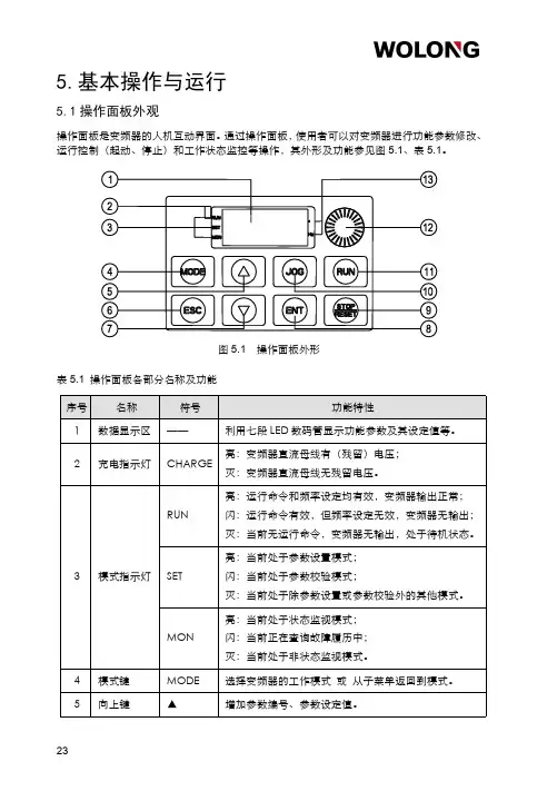
5.基本操作与运行5.1操作面板外观操作面板是变频器的人机互动界面。
通过操作面板,使用者可以对变频器进行功能参数修改、运行控制(起动、停止)和工作状态监控等操作,其外形及功能参见图5.1、表5.1。
图5.1操作面板外形表5.1操作面板各部分名称及功能序号名称符号功能特性1数据显示区——利用七段LED数码管显示功能参数及其设定值等。
2充电指示灯CHARGE 亮:变频器直流母线有(残留)电压;灭:变频器直流母线无残留电压。
3模式指示灯RUN亮:运行命令和频率设定均有效,变频器输出正常;闪:运行命令有效,但频率设定无效,变频器无输出;灭:当前无运行命令,变频器无输出,处于待机状态。
SET亮:当前处于参数设置模式;闪:当前处于参数校验模式;灭:当前处于除参数设置或参数校验外的其他模式。
MON亮:当前处于状态监视模式;闪:当前正在查询故障履历中;灭:当前处于非状态监视模式。
4模式键MODE选择变频器的工作模式或从子菜单返回到模式。
5向上键▲增加参数编号、参数设定值。
表5.1(完)操作面板各部分名称及功能序号名称符号功能特性6退出键ESC 退出当前状态,返回到上一级状态。
7向下键▼减小参数编号、参数设定值。
8确认键ENT 进入模式、查看参数或确认设定值。
9停止/复位键STOP 停止变频器输出,检出故障时变为故障复位键。
10点动复用键JOG 默认为快捷菜单3,设置详见参数f700.11运行键RUN 开启变频器输出。
12调速旋钮——调节转速。
13单位指示灯%当前显示数据为百分比。
Hz当前显示数据的单位为Hz。
5.2面板的基本操作5.2.1运行模式选择变频器共有四种运行模式:上电默认模式、参数设置模式、状态监视模式和参数校验模式。
通过MODE 键可以在四种模式之间任意切换,如图5.2所示。
(上电默认模式)(参数设置模式)(状态监视模式)(参数校验模式)0.0-f 0-u 000-uf -MODEMODEMODEMODE <1>:当f618=1时,才会显示参数校验模式。

e-mail:**************DFG70 SERIESDigital Force Gauge with MemoryServicing North America:USA:One Omega Drive, Box 4047ISO 9001 CertifiedStamford, CT 06907-0047TEL: (203) 359-1660FAX: (203) 359-7700e-mail:**************Canada:976 BergarLaval (Quebec) H7L 5A1TEL: (514) 856-6928FAX: (514) 856-6886e-mail:****************For immediate technical or application assistance:USA and Canada:Sales Service: 1-800-826-6342 / 1-800-TC-OMEGA ®Customer Service: 1-800-622-2378 / 1-800-622-BEST ®Engineering Service: 1-800-872-9436 / 1-800-USA-WHEN ®TELEX: 996404 EASYLINK: 62968934 CABLE: OMEGA Mexico:TEL: (001) 800-826-6342FAX: (001) 203-359-7807En Espan ˜ol: (001) 203-359-7803e-mail:*******************************.mxServicing Europe:Benelux:Postbus 8034, 1180 LA Amstelveen, The Netherlands TEL: +31 (0)20 6418405FAX: +31 (0)20 6434643Toll Free in Benelux: 0800 0993344e-mail:************Czech Republic:Rudé armády 1868, 733 01 Karviná 8TEL: +420 (0)69 6311899FAX: +420 (0)69 6311114Toll Free in Czech Republic: 0800-1-66342e-mail:***************France:9, rue Denis Papin, 78190 Trappes TEL: +33 (0)130 621 400FAX: +33 (0)130 699 120Toll Free in France: 0800-4-06342e-mail:****************Germany/Austria:Daimlerstrasse 26, D-75392 Deckenpfronn, GermanyTEL: +49 (0)7056 3017FAX: +49 (0)7056 8540Toll Free in Germany: 0800 TC-OMEGA SMe-mail:*****************United Kingdom:One Omega Drive, River Bend Technology Centre ISO 9002 CertifiedNorthbank, Irlam, Manchester M44 5EX, EnglandTEL: +44 (0)161 777 6611FAX: +44 (0)161 777 6622Toll Free in England: 0800 488 488e-mail:**************.ukOMEGAnet SMOn-Line Service Internet e-mail http://***************************It is the policy of OMEGA to comply with all worldwide safety and EMC/EMI regulations thatapply. OMEGA is constantly pursuing certification of its products to the European New Approach Directives. OMEGA will add the CE mark to every appropriate device upon certification.The information contained in this document is believed to be correct but OMEGA Engineering, Inc. accepts no liability for any errors it contains, and reserves the right to alter specifications without notice.WARNING: These products are not designed for use in, and should not be used for, patient connected applications.INTRODUCTIONThe DFG70 is a highly sophisticated,laboratory grade digital force gauges which offer programmable high/low setpoints for go/no go testing.Store up to 256 values into memory,which can be displayed or transmitted using digimatic or serial output e the real mode to display load transients,or the peak mode to capture the peak force achieved during a test.Select measuring units between Pounds (ounces),Kilograms (grams) and Newtons.GENERAL OPERATION1Press .After a beep,the capacity of the gauge is displayed and the gauge will automatically enter into the measuring mode.Press and hold for at least four (4) seconds each time you wish to select between pounds (ounces),kilograms (grams) and Newtons.2HAND TIGHTEN (no tool!) selected attachment to the measuring shaft.3When the gauge is turned on,it will go directly to its real time measuring mode.Press to mea-sure peak forces.“Peak icon”on the display indicates peak measuring mode,whereas the peak read-ing will not change until a higher value is measured.To delete the last peak reading,press.To endpeak reading mode and go to real time measuring mode,press again.real time mode display peak mode display4If necessary,press to tare the weight of the attachment and shaft orientation.Pressingwill also clear the peak reading.5Make sure to apply tension and compression (-) forces to thegauge in line with the measuring shaft.DO NOT attempt to mea-sure forces perpendicular to the measuring shaft - damage to loadcell and/or shaft may result.PRECAUTIONS1.REGARDLESS of whether the unit is ON or OFF,DO NOT exceed the capacity of the gauge.At 110% of the rated capacity,the gauge beeps to warn.NEVER exceed 200% of the rated capacity,or the load cell will be damaged.2When mounting DFG70,use M4 mounting screws with a maximum insertion depth of 5 mm into the gauge.3Measure in line tension and compression forces only.DO NOT attempt to measure forces perpen-dicular to the measuring shaft - damage to load cell and/or shaft may result.4Hand tighten attachments only.DO NOT use tools.5Make sure this gauge and all peripherals are powered down before attaching any cables.6DO NOT disassemble the gauge.Disassembly voids warranty.LED’sWhen high-low set pointsare set, LED indicatesbelow (-NG), within (OK),or above set point value(+NG).PEAK iconWhen continuouslydisplayed, peak hold func-tion is activated. Whenflashing, indicates peakTENSION iconDisplayed for tensilemeasurements.BATTERY iconFlashes when the Ni-Cadcells need to be charged.+PEAKselects value of digit. When programming set points inmemory mode, deletes theFULL DUPLEXCOMMUNICATIONS PORT FORCE UNITSDisplays selected measur-ing units.POWERPress and release forON/OFF. When pressed and released in conjunction with the ZERO key, all values stored in memory will be deleted.MODEAllows operator to scroll through measuring mode, programming set points mode and peak memory mode.STORE/ZEROTares weight of attach-ment. Clears Peak reading. When pressed while turn-ing on gauge, deletes all readings stored in memory. In Peak memory mode, enters each value into stored memory.-PEAKRecalls -Peak value in peak mode. Also, used for shift-ing digits when program-ming set points. In peak memory mode, displays memory space left available or when connected down-loads digimatic data.MEMORY MODE1Press until “PEAK icon”flashes on the display.2Apply tension (-) or compression (+) forces,the display will hold the peak force mea-surement (peak reading will not change until a higher value is measured).3To store this value into memory,press .The value will be stored by a confirming beep and display will automatically reset to zero and is ready for the next measurement.4Repeat this sequence for each measurement to be stored up to 256 data.Note:to redo the last stored data,press .5To review the data stored in memory,press .Each stored data will be displayed,starting with the first value stored,each timeis pressed.When all stored data have been displayed,“END”will be appear on the display.To continue storing or recalling data again,press .Note:When is pressed after is pressed,the gauge will display remaining memory space.6To download data stored in memory,choose between the following methods:RS-232:Connect the gauge to the device receiving data by using CB-202 or CB-203 ethe R [CR] uppercase ASCII command to transmit data.(See page 8).7To delete all data stored in memory,press and release while holding.Two beeps will con-firm the memory reset.PROGRAMMING SETPOINTS MODE1Press until all numeric digits flash.2As High or Low points will be recognized automatically by gauge CPU,either High or Low may be set first.To set the 1st point (High or Low),press to select desired digit.Press to select the value of each selected digit.Scroll through each digit until the value desired has been defined.Once the 1st setpoint is selected,press so that all digits will be flashing.Then press in order to set 2nd point (High or Low).While all numbers are continuously flashing,press and repeat the above sequence to select the 2nd sepoint.Again all numbers will be flashing after the 2nd setpoint is set.While setting 1st and 2nd setpoints,tension (-) or compression (+) can be selected by pressing .3After 2nd setpoints are set and all numbers are flashing,press to review and scroll High or Low setpoint values.4Press twice and return to measuring mode.With High and Low setpoints set,whether on real time measuring mode or peak measuring mode,three LED’s above the display will light:-NG (Yellow LED) :for below Low setpoint OK (Green LED) :for between setpoints +NG (Red LED) :for above high setpoint(1) Beyond 256 data,“Full”will appear.(2)Stored data will be lost if battery voltage dropslower than normal.RS232 INTERFACE FUNCTIONS1RS-232C bi-directional interface functionsAll gauge functions can be duplicated from a remote location by utilizing RS-232C interface.All commands must be sent in upper-case ASCII character format followed by a carriage return (CR).RECHARGING NI-CAD BATTERY1To maximize the life of the battery,power will automatically shut off after 10 minutes of non-use.This automatic shut off feature can be bypassed and the gauge may be used continuously when the AC adapter/charger is used.2“BATT”icon will flash when gauge needs to be recharged.To maximize battery life,do not recharge until “BATT”icon flashes.With proper recharging,the battery can be recharged 500 times.3Push to turn off power.Then use the providedadapter/charger and plug into the correct AC output.It takes 8hours to charge fully.DO NOT recharge for more than 12hours.4When the gauge is turned off,make sure the AC adapter/charg-er is disconnected.COMMUNICATIONS PORTThe communications port is divided into three separate data formats.Pins one,two and five are assigned to the full duplex,RS-232C serial interface.Pins three and six represent the ±2VDC analog output and pins four,seven and eight provide cold-contact switching circuits to remotely hold and clear the display.PORT PIN DEFINITIONS 1 RS-232C Ground2 RS-232C Signal Output3 Analog Output ±2VDC4 External Switch Display Freeze5 RS-232C Receive Signal6 Analog Ground7 External Switch Zero/clear 8 External Switch CommonShowing DFG70modelShowing DFG70 modelSignal level:RS-232C Data bits:8 bits Stop bits: 1 bit Parity bits:NoBaud Rate:2400 bps* For example:to set 1000 (compression) as high: F1000[CR]to set 0500 (tension) as low: S-0500[CR]COMMAND FUNCTIONRESPONSEB [CR]Delete last data stored in memory R [CR] executed E [CR] errorC [CR]High/Low setpoint comparisonR [CR] OK U [CR] +NG L [CR] -NG E [CR] errorF±____[CR]*Select high setpoint R [CR] executed S±____[CR]*Select low setpointE [CR] errorH [CR]Recall +peak (compression)[value] [unit] P [CR] executed E [CR] errorU [CR] Recall -peak (tension)[value] [unit] P [CR] executed E [CR] errorI [CR] Clear Memory R [CR] executed E [CR] errorR [CR]Recall all memory data[value] [unit] M [CR][value] [unit] M [CR]R [CR] executed E [CR] errorW [CR]store data in memory R [CR] executed E [CR] errorD [CR]transmit display data[value][unit][mode][CR] executed E [CR] errorK [CR]select “Kg” units N [CR]select “N” units L [CR]select “lb” unitsO [CR]select “oz” units (only oz model)R [CR] executed P [CR]select peak mode E [CR] errorT [CR]select real time mode Z [CR]tare display Q [CR]turn off power2±2 VDC Analog SignalConnect the CB-101 analog cable to the full duplex port and the device receiving the data.3External Switch Display FreezeBy connecting (use contact closure and DO NOT apply voltage across) #4 and #8 of the communications port,the gauge instan-taneously captures the critical reading and holds the display from remote locations.[mode] = T: Real time, P: Peak [units] = K: Kg, N: Newtons, L: Pounds, O: Ounces5External Switch Display ClearBy connecting (use contact closure and DO NOT apply voltage across) #7 and #8 of the communications port,display may be cleared from remote locations.CAPACITY MODEL Pounds Grams Newtons OuncesKilograms DFG70-0.58.818 oz (0.001 oz)250.0 g (0.1 g) 2.450 N (0.001 N)DFG70-117.63 oz (0.01 oz)500.0 g (0.1 g)4.900 N (0.001 N)DFG70-4 4.410 lb (0.001 lb) 2.000 kg (0.001 kg)19.60 N (0.01 N)DFG70-1111.02 lb (0.01 lb)5.000 kg (0.001 kg)49.00 N (0.01 N)DFG70-4444.10 lb (0.01 lb)20.00 kg (0.01 kg)196.0 (0.1 N)DFG70-110110.2 lb (0.1 lb)50.00 kg (0.01 kg)490.0 N (0.1 N)DFG70-220220.4 lb (0.1 lb)100.0 kg (0.1 kg)979.0 N (0.1 N)Accuracy± 0.1% ± 1 LSD Display Update 20 updates/secondSelectable Units Displays values in grams/kilograms, ounces/pounds or newtonsOverload Capacity 200% full scalePowerFour internal AA Ni-Cad cells, eight hour capacity when fully charged with AC adapterLow Battery Indicator Display flashes BATT when battery is low CPU8-bit CMOSA/D Converter 16-bit Delta Sigma SystemMemoryNonvolatile, recall up to 256 measurements Peak Memory Recalls peak tension and compressionSetpoints Programmable high/low setpoints with color coded indicator.Dimensions9.6 x 2.9 x 1.2 in (245 x 73 x 30.5 mm)Ambient Temperature 32° to 100°F; 0 to 40°C Weight18 ounces Shipping Weight 4 poundsOutput PortsRS232C:Full duplex, 2400 baud, 8 data bits, no parity bit, 1stop bitAnalog:±2VDC full scaleIncluded AccessoriesAC adapter/charger; eight attachments: (3 hooks, flat tip, chisel tip, notched tip, conical tip, extension shaft) and hard-plastic carrying caseSPECIFICATIONSDFG70 RANGES (Resolution)DIMENSIONSDirect all warranty and repair requests/inquiries to the OMEGA Customer Service Department. BEFORE RETURNING ANY PRODUCT(S) TO OMEGA, PURCHAS ER MUS T OBTAIN AN AUTHORIZED RETURN (AR) NUMBER FROM OMEGA’S CUS TOMER S ERVICE DEPARTMENT (IN ORDER TO AVOID PROCESSING DELAYS). The assigned AR number should then be marked on the outside of the return package and on any correspondence.The purchaser is responsible for shipping charges, freight, insurance and proper packaging to prevent breakage in transit.FOR WARRANTY RETURNS, please have the following information available BEFORE contacting OMEGA:1.P.O. number under which the product wasPURCHASED,2.Model and serial number of the product underwarranty, and3.Repair instructions and/or specific problemsrelative to the product.FOR NON-WARRANTY REPAIRS,consult OMEGA for current repair charges. Have the following information available BEFORE contacting OMEGA: 1. P.O. number to cover the COSTof the repair,2.Model and serial number of product, and3.Repair instructions and/or specific problemsrelative to the product.OMEGA’s policy is to make running changes, not model changes, whenever an improvement is possible. This affords our customers the latest in technology and engineering.OMEGA is a registered trademark of OMEGA ENGINEERING, INC.© Copyright 1996 OMEGA ENGINEERING, INC. All rights reserved. This document may not be copied, photocopied, reproduced, translated, or reduced to any electronic medium or machine-readable form, in whole or in part, without prior written consent of OMEGA ENGINEERING, INC.Where Do I Find Everything I Need for Process Measurement and Control?OMEGA…Of Course!TEMPERATUREⅪߜThermocouple, RTD & Thermistor Probes, Connectors, Panels & AssembliesⅪߜWire: Thermocouple, RTD & ThermistorⅪߜCalibrators & Ice Point ReferencesⅪߜRecorders, Controllers & Process MonitorsⅪߜInfrared PyrometersPRESSURE, STRAIN AND FORCEⅪߜTransducers & Strain GaugesⅪߜLoad Cells & Pressure GaugesⅪߜDisplacement TransducersⅪߜInstrumentation & AccessoriesFLOW/LEVELⅪߜRotameters, Gas Mass Flowmeters & Flow ComputersⅪߜAir Velocity IndicatorsⅪߜTurbine/Paddlewheel SystemsⅪߜTotalizers & Batch ControllerspH/CONDUCTIVITYⅪߜpH Electrodes, Testers & AccessoriesⅪߜBenchtop/Laboratory MetersⅪߜControllers, Calibrators, Simulators & PumpsⅪߜIndustrial pH & Conductivity EquipmentDATA ACQUISITIONⅪߜData Acquisition & Engineering SoftwareⅪߜCommunications-Based Acquisition SystemsⅪߜPlug-in Cards for Apple, IBM & CompatiblesⅪߜDatalogging SystemsⅪߜRecorders, Printers & PlottersHEATERSⅪߜHeating CableⅪߜCartridge & Strip HeatersⅪߜImmersion & Band HeatersⅪߜFlexible HeatersⅪߜLaboratory HeatersENVIRONMENTALMONITORING AND CONTROLⅪߜMetering & Control InstrumentationⅪߜRefractometersⅪߜPumps & TubingⅪߜAir, Soil & Water MonitorsⅪߜIndustrial Water & Wastewater TreatmentⅪߜpH, Conductivity & Dissolved Oxygen InstrumentsM3514/1099。
前言承蒙您此次购买XK3201(F701P/PD)称重显示控制器,请接受我们真诚的谢意。
为了使您能够正确地使用该仪器,充分发挥XK3201(F701P/PD)的良好性能,希望您能在使用仪器之前,务必阅读本使用说明书。
【注意】※不得擅自转载本说明书的部分或全部内容。
※将来对本书进行修改时,不再另行通知。
※本说明书在编写中,虽然力求完善无误,但是难免有疑点,错误和遗漏之处。
当您发现时敬请告知,谢谢各位的大力协作。
目录一、性能介绍及主要技术指标 (4)二、使用之前 (5)三、安全注意事项 (6)四、仪表安装 (7)五、仪表外形图 (8)六、各部分的名称和功能(正面) (10)1. 重量显示区 (10)2. 菜单显示器 (10)3. 按键说明 (11)4.校秤操作 (11)5.显示器显示状态 (12)6.设置时输出检测提示 (13)7.仪表显示状态含义 (13)七、各部分名称和功能(后面) (14)1.传感器输入口 (14)2.模拟输出口(选配件) (16)3.AC220V电源输入插座 (16)4.通讯口串口插座编号 (16)5.输入信号 (16)6.输出信号(低电平输出有效) (17)八、设置方法 (20)九、参数说明 (22)☆参数设置的操作方法 (26)1.配方设定功能的设置 (26)2.产量累计的查看及清除 (29)3.仪表自检功能3栏目 (30)4.基本时间设置功能4栏目 (31)5.校秤参数设置及调校操作功能5栏目 (35)6.测量模式功能6栏目 (37)7.运行模式功能7栏目 (40)8.通讯模式功能8栏目 (43)9.附加模式功能9栏目 (45)十、XK3210P01配料控制器通讯协议 (48)一、性能介绍及主要技术指标★仪表采用嵌入安装方式小型尺寸,铝合金型材外壳,外形美观大方、体积小巧、结构牢固、散热性能好、抗干扰性能强等优点。
★高操作性能人机界面丰富,采用组合键输入方式,操作方便可靠。
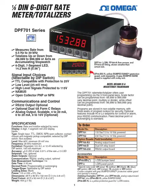
11⁄8 DIN, FP7001A flow sensor, andTM protective U M easures Rate from 0.5 Hz to 30 kHz U T otalizes Up or Down from -99,999 to 999,999 or Acts as Accumulating Stopwatch U 6-Digit, 7-Segment LED, 14.2 mm H (0.56")Signal Input Choices(Selectable by DIP Switch)U TTL Compatible with Protection to 25V U Low Level (25 mV rms)U High Level Signals Protected to 115V U NAMURU Open Collector PNP or NPNCommunications and ControlU RS232 Output OptionalU Optional Dual 5A Form C RelaysU A nalog Output, Scalable, 4 to 20 mA, 0 to 20 mA, 0 to 10V (Optional)The DPF701 ratemeter/totalizer offers userprogramming via the 5 front-panel keys. Scale factor can be programmed from -99,999 to 999,999(any decimal point, multiply or divide), while offset can be programmed from -99,999 to 999,999 (any decimal point).Programs are stored in non-volatile memory, with three levels of program lockout for security. Optional features include Hi or Lo setpoints for control or alarm, plus RS232 communication. Fixed decimal point or autoranging is standard.SPECIFICATIONSFunctions: Rate and totalize selected by menu Display: 6-digit, 7-segment red LED display InputsType: Single input. TTL, CMOS, NPN open collector, contact closure and magnetic pickup compatible; selected by DIP switch. Non-isolated.Level: Max 60V; minimum 25 mV rms Frequency: 30 kHz maximumExcitation:Regulated, 5.0, 8.2, or 12.4V selected by DIP switch, 100 mA maximumAccuracy: ±0.5 LSD of total; 0.01% of the rate ±1.5 LSD Setpoints: Two, optional Alarm Outputs: OptionalCommunication: RS232, analog output, optional Rate Measurement Technique: 1/x Gate Time: 0.30 secDecimal Point: Programmable or autoranging Trigger Slope: Selectable by DIP switch Leading Zeros: BlankPower: 115 or 230 ±15% VacDimensions: 48 H x 96 W x 152 mm D (1.9 x 3.8 x 6")Panel Cutout: 45 H x 92 mm D (1.8 x 3.6")Weight: 454 g (1 lb)GR (green), RD (red), OR (orange), VL (purple) or WH (white).Comes complete with gray BUMPER BAND TM protective rubber guard and operator’s manual.Ordering Examples: DPF701, plus DPF700-A3, analog output board. DPF702, plus DP40-BB-YL ,yellow BUMPER BAND .DP40-BB-YL is a yellow protective guard for 1⁄8 DIN meters.1⁄8 DIN 6-DIGIT RATE METER/TOTALIZERSBEZEL DESIGN IS A REGISTERED TRADEMARKDPF701 Series。
741B/743B过程仪表认证校准仪用户手册本中文手册为 F741B/F743B 的使用说明,对 F701/F702/F741/F743 也基本适用,但有些功能仅限 F741B/F743B。
如有使用中的问题请和 Fluke 公司办事处联系。
本中文手册译自英文原版,其目的是为用户正确地和方便地使用仪器提供帮助。
所以,本手册仅供此目的参考使用,一切以英文原版为准,当英文手册有所更动时将不通知已有此手册的用户。
过程仪表认证校准仪一、引言Fluke 741B 和 743B 过程仪表认证校准仪(以下简称校准仪)是由电池供电,测量和输出电参数和物理参数的一种手持便携式仪器(见表 1)。
该仪器可使你对过程仪表进行故障诊断,校准,鉴定以及文件档案记录。
详见本手册后面的技术指标。
741B 和 743B 校准仪所提供的测量输出功能列于表 1。
表 1 测量和信号输出功能一览表除表 1 所列的功能外,741B/743B 校准仪还具有下列特性:·一般特性:在测量方式中,当输入信号不稳定时,模拟显示可容易读出测量值,并告之当前输入信号不稳定。
显示信息可用英语、法语、德语、意大利语和西班牙语五种语言表达。
热电偶输入/输出插孔与内部等温体相连并带有自动参考节温度补偿,或者,可手动插入外部参考温度。
存储校验结果以备以后检查。
·测量模式的特性稳定读数(对最后的几个读数进行平滑)以工程单位,刻度百分比平方律输入和用户定义单位显示测量参数。
捕捉并显示测量的最大最小值。
图 1 标准设备三、安全信息本校准仪是按照 IEC1010-1 和CAN/CSA C22.2 No1010.1-92 标准进行设计和工作的,请参照本手册或快速参考指南使用本仪器,否则的话,本仪器所提供的保护措施将受到限制。
WARNING(小心)的符号表明会对用户造成危险的环境和操作。
CAUTION(警告)的符号表明会损坏校准仪或被测试的设备。
本仪器所使用的符号如图 2 所及说明。
HSF600系列高性能变频器使用说明书成都森沃电气有限责任公司序言感谢您选用成都森沃电气有限责任公司生产的HSF600系列高性能变频器!在安装、操作、维护、检查变频器之前,请认真阅读本使用说明书,充分发挥变频器功能,确保使用者安全。
本使用说明书简要介绍了HSF600系列变频器的性能、安装接线、参数设定及操作使用的有关事项。
在使用(安装、运行、维护、检查等)前,请务必认真阅读。
另外,请在理解产品的安全注意事项后再使用该产品。
本使用说明书的示图,是为了方便说明,可能与产品会略有不同,由于产品升级,也有可能略有不同,请以实物为准。
请注意将本使用说明书交到最终用户手中,并妥善保存,以使日后检修、维护时使用。
随着产品的不断改善,本手册如有变更,恕不另行通知。
如有疑问,请及时与本公司或本公司代理商取得联系,我们将竭诚为您服务。
目录1.开箱检查注意事项 (1)2.安全注意事项 (2)2.1 安全标识 (2)2.2 安全事项 (2)3.产品信息 (5)3.1 型号说明 (5)3.2 系列规格 (5)3.3基本性能及配置 (7)3.4结构及外形安装尺寸 (9)3.5保养与维护 (13)3.6保修 (15)3.7报废 (15)4.安装与接线 (16)4.1机械安装 (16)4.2电气接线 (18)5.基本操作与运行 (26)5.1操作面板外观 (26)5.2面板的基本操作 (27)5.3通电 (30)5.4运行 (31)6.功能参数 (38)6.1 参数简表 (38)6.2基本参数组 (65)6.3电机及其保护参数组 (71)I6.4电机控制参数组 (73)6.5输入输出端子参数组 (78)6.6故障保护参数组 (99)6.7电机启停参数组 (107)6.8键盘面板参数组 (114)6.9附加功能参数组 (118)6.10通信功能参数组 (123)6.11过程PID参数组 (127)6.12监视功能参数组 (131)7.故障诊断与对策 (134)7.1 故障代码、原因与对策 (134)7.2 提示和报警代码说明 (137)7.3 故障发生后变频器的再起动 (138)附录A:串行通信 (139)A1.RS485总线 (139)A2.Modbus协议 (140)附录B:制动单元/电阻选型 (150)II1.开箱检查注意事项在开箱时,请仔细确认:(1)箱内含有您订购的机器、产品合格证、产品说明书及保修单;(2)机器侧面铭牌上的产品型号是否与您的订购要求一致;(3)产品在运输过程中是否有破损现象;(4)若发现有某种遗漏、损坏或其他问题,请速与本公司或代理商联系解决。
吨包装秤系统操作、维护说明书目录一.吨包装系统 (1)1.概述 (1)2.主要参数与技术参数 (1)3.系统组成 (2)4.系统工作原理 (2)5.安装 (3)6.调试 (3)7.使用方法 (4)二.设备一般故障及排除方法 (5)三.注意事项 (6)一.吨包装系统I.概述吨包装(大包装)系统是专为粉料、粒料、片料生产的一体化产品,它由进料机构、夹袋机构、称重机构、挂袋机构、吹气机构、皮带输送机、电气控制部分、机架等组成。
整个系统具有良好的可靠性及长期稳定性,智能化程度高操作方便,维护工作量小等特点。
II. 主要参数与技术参数1.吨包装的技术参数精度等级:0.2额度称量:500kg-1000kg/包包装能力:10—20袋/小时给料方式:自由给料或螺旋给料2.称重仪表的性能指标型号:F701称重误差检测:称重超差报警非线性:0.01%FS零点漂移:0.2uV/℃最小输入灵敏度:0.5uV/每个分度最小指示分辨率:1/10000输入控制信号:干接点或无接点的晶体管信号输出控制信号:晶体管开路集电极输出其它:自动零点校准,故障自诊断,直接输出打印信号III.系统组成1.称量部分由进料机构、夹袋机构、挂袋机构、电子台称等部分组成。
2.皮带输送机部分由输送机架、辊子输送机及减速机等组成。
3.控制部分由高精度称重仪表F701、三菱系列可变程控制器、电磁阀及执行元器件如气缸、接触器等组成。
4.辅助部分主要有机架等部分组成IV:系统工作原理将包装秤、皮带输送机等设备移至工作区,并安装调试。
将空包装袋置于秤台上,人工将袋子挂在四个挂钩上,袋口套在下料口上,然后触碰夹袋开关,夹袋机构动作将包装袋夹紧,接着打开吹气电磁阀,气体将包装袋撑开,延时数秒钟后将电磁阀关闭。
按下秤启动按钮后仪表首先进行置零操作,然后排气电磁阀打开,进料机构料门开启,加料开始,称重传感器将实际重量换成电信号,称重控制仪表将模拟量电信号转换成数字量电信号并与设定值自动进行比较,通过PLC可变程控制器和各执行元件进行粗加料,细加料自动落差补偿等动作,最后完成定量罐装过程。

CJD自动定量包装机电控使用说明书无锡力马化工机械有限公司一、概述:电子秤包装机,其核心部分为电子秤控制系统。
本说明书主要对电子称重灌包部分作技术说明。
电气控制系统采用称重控制器和可编程序控制器(以下简称PC机)作核心部件。
它们都是采用微机处理器的智能化仪表。
称重控制器对称重信号采集和处理;PC机可对整个动作过程进行协调和控制。
该电控系统具有零位自动修正、自动去皮、空中量补偿、计量自动累加等功能,不仅计时速度快,而且计量精确度高。
很适合于工厂、仓库、码头、矿山的颗粒状和粉状物料的称重和灌包。
由于采用了先进的智能化仪表,整个控制系统结构紧凑、体积小、重量轻、线路简单、寿命长、工作可靠、操作及维护十分方便。
二、工作环境条件:1、海拔高度:不超过200米。
2、工作温度:0~40℃。
3、相对温度:10~85%,不凝露。
+10%+2%4、电源电压:220V ,50HZ 。
-15%-2%5、冲击:X、Y、Z方向<10g3次。
6、振动:<3mmp-p,<15HZ。
7、空气介质:无爆炸危险,无腐蚀及无可燃气体。
8、接地电阻:<4Ω(单独接地)。
三、系统组成及工作原理:1、组成:控制系统由电控柜、操作箱、气控箱、荷重传感器、套袋开关等组成。
电控柜内部装有PC机、变压器、整流器等电器,箱门上装有称重控制器,各种按钮、开关和指示灯等。
2、工作原理:1、称量过程:按秤启动按钮,打开A、B秤操作开关。
人工发出操作信号后(或者产生放料完毕信号),若此时秤桶是空的,传感器使称重控制器产生一个空秤信号。
PC机接到这一信号后,向称重控制器发出启动命令,称重器发出粗、细加信号,使粗、细加料电磁阀动作,形成粗加料过程。
当物料加入秤桶内,传感器产生的信号达到称重器设置的粗加设定点SP2时,粗进电磁阀关断,进料转为细加料过程。
随着物料不断加入秤桶,传感器产生的信号达到称重器设置的细加设定点SP3,细进电磁阀关断,细加料过程结束。
细加料结束后,通过一定延时,空中物料落入秤桶,便发出称完信号。
厂商声明胜利高公司向最初购买该仪表的购买者承诺:自购买之日起一年内在正常使用情况下给予保修,并免费更换材料(不包括保险丝、测试表笔)。
本公司不承担在不正常的条件下操作使用万用表而造成的对仪表和人员造成的损害。
要获得本公司的服务,请与本公司最近的仪器服务中心联系或将产品连同有关产生问题的说明、邮资一起寄到最近的仪器服务中心。
本公司不承担在邮递当中的损害,本公司将免费维修或更换出错的产品或退还您所购买产品的费用。
然而,如果本公司检测出这些错误是由于误用、更换、事故或不正常的条件下使用或操作而引起的,您将要为维修而付维修费,维修好的产品将退回给您。
运回产品维修或校准仪表应该经过统一包装“快递”到本公司。
仪表应该被装在出厂纸板箱里以便运输。
如果没有可用的纸箱,使用大小合适的牢固的容器进行包装,如果使用替代品,仪表应该用纸预先包装,并且用类似的减震材料围在周围。
对最初购买者有关在运输中的损坏声明仪表运送到购买者处,购买者应立即全面检查仪表,盒子里的所有材料应该对照附带的包装单进行核对检查。
如果仪表以任何方式损坏,应及时通知运送者。
如要修理由于运输而损坏的仪表,请与最近的胜利仪器服务中心联系。
由于运输损坏与运输公司的赔偿协商应由顾客来完成。
使用本手册注意事项●本用户手册内容如有改变,恕不另行通知。
●本用户手册的内容被认为是正确的,若用户发现有错误、遗漏等,请与生产厂家联系。
●本公司不承担由于用户错误操作所引起的事故和危害。
●本用户手册所述的功能不作为将本产品用作特殊用途的理由。
24/2目录1、概述 (4)2、开箱检查 (5)3、安全注意事项 (6)4、安全符号说明 (7)5、仪表面板及按键功能说明 (8)6、按键开关………………………………………………………………………………………9-107、显示屏幕………………………………………………………………………………………11-128、特性 (13)9、直流电压(DCV) (14)10、交流电压(ACV) (15)11、直流电流(DCA) (16)12、交流电流(ACA) (17)13、电阻 (18)14、二极管及通断测试 (19)15、电容(C) (20)16、频率(Hz)及仪表保养………………………………………………………………………21-2324/3一.概述VICTOR70F一种智能型、性能稳定、高可靠性、3 3/4数字多用表,仪表采用33mm字高LCD 显示器,读数清晰,显示直观,操作方便,可用来测量直流电压、交流电压、直流电流、交流电流、电阻、电容、频率、二极管及通断测试;同时还有单位符号显示、数据保持(HOLD)、最大最小値测量(MAX/MIN),相对值测量(REL),数据存储(SAVE),数据读取(MEM),时间显示(year/month/day/hour/minute/second),自动/手动量程转换(AUTO/RANGE)、自动断电及报警功能(15分钟)、采用面板校准技术。

F701C简易说明-继续完善(总11页)--本页仅作为文档封面,使用时请直接删除即可----内页可以根据需求调整合适字体及大小--HYTEC ELECTRONIC包装秤F701C仪表操作/设定简易手册目录1.概述................................................................. 错误!未定义书签。
2.面板介绍............................................................. 错误!未定义书签。
3.参数设定............................................................. 错误!未定义书签。
秤的标定.......................................................... 错误!未定义书签。
零点校正.......................................................... 错误!未定义书签。
量程校正.......................................................... 错误!未定义书签。
工作方式设定...................................................... 错误!未定义书签。
目标值设定........................................................ 错误!未定义书签。
慢加值设定........................................................ 错误!未定义书签。
中速加料值设定.................................................... 错误!未定义书签。
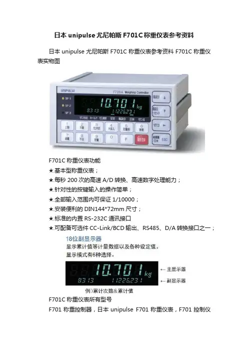
日本unipulse尤尼帕斯F701C称重仪表参考资料日本unipulse尤尼帕斯F701C称重仪表参考资料F701C称重仪表实物图F701C称重仪表功能★.基本型称重仪表;★.每秒200次的高速A/D转换、高速数字处理能力;★.针对性的按键输入的操作简单;★.全部输入范围内可保证1/10000;★.安装便利的DIN144*72mm尺寸;★.标准的内置RS-232C通讯接口★.可配备可选件CC-Link/BCD输出、RS485、D/A转换接口之一;F701C称重仪表所有型号F701称重控制器,日本unipulse F701称重仪表,F701控制仪表F701C称重控制器,日本unipulse F701C称重仪表,F701C控制仪表F8O5A BC称重控制器,日本unipulse F8O5A称重仪表,配料秤专用F8O5A FB称重控制器,日本unipulse F8O5A称重仪表,包装秤专用F701C称重仪表外观尺寸F701C称重仪表技术参数F701F701CDC10V±5%输出电流不超过120mA 激励电压DC10V±5%,输出电流120mA以内,长线补偿设计(最多可并联4个350Ω传感器)2mV/V 零点调整粗调:约0.5mV/V、1mV/V输入选择,能够零点调整『仪表背面的开关』非线性0.01%/FS以内0.01%/FS以内零点漂移0.2μV/℃以内0.2μV/℃以内量程漂移15ppm/℃以内15ppm/℃以内A/D转换器100次/秒200次/秒最小输入分度0.5μV/count0.4μV/countF701C称重仪表性能F701F701C交流110V~240V(+10%-15%)电源电压交流85V~110V、102V~132V、170V~220V、187V~242V(订货时指定)消耗功率1515使用温度-10℃~+40℃-10℃~+40℃使用湿度85%RH以下(无凝霜)85%RH以下(无凝霜)外形尺寸192(W)×96(H)×160(D)mm(不含凸起部分)144(W)×72(H)×160(D)mm138(W)×68(H)mm 安装尺寸186(W)×92(H)mm,※安装板的厚度在1.6mm以上重量约2.2kg约1.0kg。
FR700V SERIES FUEL TRANSFER PUMPSInstallation and Operation ManualTable of ContentsThank You! (2)Warranty Policy (2)About This Manual (3)Safety Information (3)Installation (3)Anti-Siphon Device (5)Electrical Wiring (6)Wiring Procedure (6)Operating Instructions (7)Safety Testing Approvals (7)Padloocking (7)Fluid Compatibility (7)Technical Information / Specifications (7)Accessories (8)Troubleshooting (8)Replacement Parts Information (10)FR700V / FR701V / FR710V / FR711V Parts List (10)700VE Model Information ....................................................................................12Thank You!Thank you for your loyalty to the Fill-Rite® brand of fuel transfer pumps. Your safety is important, so please read and thoroughly understand the procedures set forth in this manual. In addition, please save these instructions for future reference and record the model, serial number, and purchase date of your fuel transfer pump. Protect yourself as well as those around you by observing all safety instructions and adhering to all danger, warning, and caution symbols. Please register your Fill-Rite® product via /product_registration. IMPORTANT RETURN POLICYPlease do not return this product to the store. For all warranty and product questions, please contact Fill-Rite Technical Support at 1 (800) 720-5192 or via********************************(M-F,8AM–5PMET).Limited Warranty PolicyFill-Rite Fort Wayne warrants the goods manufactured shall be free from defects of materials and workmanship. Specific warranty details for individual products can be found at .About This ManualFrom initial concept and design through its final production, your Fill-Rite pump is built to give you years of trouble-free use. To insure it provides that service, it is critical that you read this entire manual prior to attempting to install or operate your new pump . Become familiar with the terms and diagrams, and pay close attention to the highlighted areas with the following labels:At Fill-Rite, your satisfaction with our products is paramount to us. If you have questions or need assistance with your product, please contact us at 1 (800) 720-5192 or via email at *************************(M-F,8AM–5PMET).Safety InformationInstallationThe Fill-Rite FR700V Series pump is designed to offer several different mounting configurations. It can be mounted on a skid tank using the tank adapter supplied with the pump (see attached diagrams) or mounted on a concrete island using an optional pedestal adapter (available through your Fill-Rite distributor). Regardless of mounting style, all tanks must be properly vented.The FR700V Series pump has a built-in check valve with pressure relief to reduce unsafe excess pressure from thermal expansion of the fluid. It also features an integral bypass valve to help minimize wear when the pump is operating with the nozzle closed.NOTICETypical Skid Tank InstallationMaterials • 1-1/4" pipe cut to a length that will terminate at least 3" from the bottom of thetank when installed into the tank adapter with the tank adapter installed into thetank flange (see SKID TANK INSTALLATION diagram).• Threaded pipe joint sealant appropriate for application.Installation Procedure1. Thread the 1-1/4" pipe into the tank adapter. Seal threads liquid tight withappropriate thread sealant.2. Screw the tank adapter into the tank flange; seal threads liquid tight withappropriate thread sealant.3. Mount the pump on the adapter; seal threads liquid tight with appropriatethread sealant.4. Fill-Rite recommends installation of an Anti-Siphon Device.Typical “Pedestal / Island” Installation Materials• 1-1/4" threaded suction pipe, cut to extend 32-1/2" above the island.• FRPA125 Pedestal Kit (includes Pedestal Pipe, Base, & Coupler).• Threaded pipe joint sealant appropriate for application.Installation Procedure 1. Remove the coupler from the pedestal pipe by loosening the set screws.2. Slip the pedestal pipe/pump base assembly over the 1-1/4" suction pipe.3. Loosen the screws in the pedestal base to allow the pedestal pipe to slide downexposing the end of the suction pipe.4. Screw the coupler onto the suction pipe; seal threads liquid tight withappropriate thread sealant.5. Slide the pedestal pipe into the coupler and tighten the set screws.6. Tighten the screws in the pedestal base.7. Mount the pump on the coupler seal threads liquid tight with appropriate thread sealant.Bung Adapter / Suction Pipe Assembly and InstallationFR700V Series pumps feature a 2" Bung Adapter with integral connection for ananti-siphon device. When installing the suction pipe into the bung adapter, the suctionpipe must be inserted into the bung adapter correctly for proper operation. The suctionpipe threads into the tank adapter, and must be cut to a length that positions it at least 3" from the bottom of the tank.1. Measure and cut suction pipe to fit as described above.2. Examine the bung adapter to determine top and bottom for proper insertion ofthe suction pipe. The bung adapter is labeled to help: the end marked “PUMPSIDE” is the top of the bung adapter. Note that the internal threads for thesuction pipe are at the TOP of the opening.3. Wrap the threads of the suction pipe with the appropriate sealant for the fluidbeing pumped. Insert the suction pipe (with the threaded side up) into thebottom of the bung adapter until the threads engage.4. Tighten the suction tube into the bung adapter to create an air / fluid tight seal.5. Apply an anti-seize thread compound to the external threads on the bottom ofthe bung adapter. Install the assembled bung adapter and suction pipe into thebung opening on the tank. Tighten to a fluid / air tight seal.6. Install pump onto bung adapter using appropriate fluid sealant, and tighten to a fluid / air tight seal.Anti-Siphon DeviceYour FR700V Series pump comes from the factory ready to install an anti-siphon tubeback to the tank. An anti-siphon device (a.k.a. vacuum breaker) is important because it will break a liquid siphon if there is an open nozzle or a leaking hose below the fluid levelin the tank when the pump is turned off. Fill-Rite recommends anti-siphon kit # KIT700ASbe installed from the pump outlet back to the vapor space in the tank.This illustration shows where to install the tube so that it terminates in the vapor space atthe top of the tank. The tube must terminate in the vapor space; if it terminates below thefluid level in the tank, it will not prevent siphoning. It is very important there are no liquid traps in the tubing; it must have a continuous slope from the pump down to the tank, andcan be connected into any opening in the top of the tank if the tank adapter is not used.Use reducer bushings as required for proper fit and seal.The 1/4" NPT opening in the side of the tank adapter terminates in the vapor space of thetank. Make liquid tight connections using the appropriate sealant from the adapter to theanti-siphon outlet using a minimum of 1/4" metal tubing that is compatible with whateverliquid is being pumped. If the anti-siphon tank adapter is being used and the 1/4" NPTopening is not used for the tubing, leave the factory installed plug in place.Fill-Rite offers Anti-Siphon kit # KIT700AS (available through your Fill-Rite distributor).This kit contains the necessary fittings and tubing to complete the installation as picturedin this section. NOTE: This kit ONLY works for tank top installations.If not using the KIT700AS, you will need the KIT700AVB. This will allow you to connect a line either back to the tank, or to the bung adapter.TOP1 1/4" SUCTION PIPEWiring ProcedureNote that the ground wire MUST be connected.3. Tuck the wires back into the junction box, verify proper placement of gasket, align cover with junction box holes and reinstall screws. Torque each screw to 90 ± 9 e the Voltage Selector Switch on the end of the pump to select the input voltage for the pump. NOTE: The pump comes from the factory pre-set to 115V AC position.Electric WiringNOTICEOperating Instructions1. Reset Meter to “0” (if applicable).2. Remove dispensing nozzle from nozzle boot.3. Move the switch lever to the “ON” position to power the pump.4. Insert the dispensing nozzle into the container to be filled.5. Operate the nozzle to dispense fluid; release nozzle when the desired amount offluid has been dispensed.6. Move switch lever to the “OFF” position to stop the pump.7. Remove the dispensing nozzle from the container and store it in the nozzle boot.PadlockingYour Fill-Rite pump nozzle can be padlocked for added security. With the pump turned off, and the nozzle in the stored position, a padlock can be inserted through the nozzle rest and nozzle handle opening. This configuration prevents the nozzle from being removed from the nozzle cover.Technical Information / SpecificationsDesign Features:• Inlet: Bung : 2" male NPT; Suction pipe- 1¼" female NPTfor FR705VE / 705VEL / 715VE Bung: 2" male BSPT;Suction pipe- 1" female BSPP.• Outlet: 3/4" NPT (model FR700V / 701V) / 1" NPT (model FR710V / 711V)for FR705VE / 705VEL / 715VE Outlet.• Cast iron pump housing: iron (composite) rotor, and carbon (composite) vanes.• Model FR700V / 701V furnished with UL listed 3/4" x 12' hose and manual nozzle.• Model FR711V furnished with one UL listed 1" x 18' hose and automatic nozzle.• Security: Pump equipped for padlocking.• Thermal overload protection.• Heavy duty switch.• 30 minute duty cycle.• Explosion proof motor UL listed with sealed bearings that requireno maintenance.• Integral check valve with pressure relief on outlet side prevents pressure build up and improves vertical lift.• Easy access strainer.• Automatic bypass valve.• 2" threaded base for tank openings.• Constant Amp Draw (service factor of 1.0):- 115VAC 60Hz – 5.5 amps- 230VAC 60Hz – 2.4 amps Overall Dimensions:Model FR700V / 710V: 14.15" wide X 11.825" high x 11.5" deep.Model FR701V: 14.15" wide X 16.6" high x 11.675" deep.Model FR711V: 15.25" wide x 16.1" high x 14.1" deep.Shipping Weight:FR700V: 54 lbs. / FR701V: 61 lbs. / FR710V: 54 lbs. / FR711V: 61 lbs. Accessories:• See page 8 for a complete list of available accessories.Performance:• 25 psi (1.72 bar) maximum pressure @ pump outlet.• Up to 20 gallons (75 liters) per minute.• Fluid pump with maximum viscosity: #2 diesel fuel.• Maximum pump operating temperature (ambient): 150 degrees F (66 degrees C).• Minimum pump operating temperature (ambient): minus 13 degrees F (minus 25 degrees C) (note that for operation at lower temperatures, we recommend the“Arctic Nozzle” and “Arctic Hose” in the accessories section on page 8).• Maximum suction lift: 10' (3 m) for gasoline; 18' (5.5 m) for #2 diesel fuel(the lift in feet is equal to the vertical distance from the surface of the fluid in the tank to the inlet of the pump, LESS friction losses through the vertical and horizontal runs of pipe, all elbows, and other fittings. System should be set up to require a minimum amount of suction lift).Safety Testing ApprovalsThe Fill-Rite line of pumps have been safety tested forcompliance to the standards set forth by UL Laboratories.TroubleshootingThe following Troubleshooting guide is provided to offer basic diagnostic assistance in the event you encounter abnormal service from your Fill-Rite product.If you have questions regarding installing, operating, or servicing your product, please feel free to contact our Technical Support at 1 (800) 720-5192 or via email at*************************(M-F,8AM–5PMET).AccessoriesA wide variety of accessories are available to help you maximize the performance of your FR700V Series pump. Listed below are the applicable available accessories for your specific product.Please contact your authorized Fill-Rite distributor to purchase the accessories you need.Troubleshooting (Continued)Bold text indicates repairs that are not serviceable by the owner; please refer to our Warranty Policy on page 2 for further instructions.* Repairs marked with an asterisk (*) will require Repair Kit #700KTF2689.. This kit includes a replacement rotor and new vanes, as well as a number of other important seals and components to complete the repair. Details of this kit are on page 10.Replacement Parts InformationFor repairs or routine maintenance, Fill-Rite offers the parts you need. The following parts diagram and list covers all applicable parts for your Fill-Rite product. These parts can be obtained through any authorized Fill-Rite dealer. Be sure to use only genuine Fill-Rite replacement parts for your service and maintenance needs. For a list of authorized dealers,please visit .KIT700CV - Check valve assemblyKIT700SG - Screen and gasket kit 11FR700V / FR701V / FR710V / FR711V Parts ListMaterials of ConstructionMaterials of construction of the external surface of the unit are: painted steel; painted cast iron; painted aluminum; zinc plated steel.Materials of construction of the wetted parts are: cast iron; steel; zinc plated steel; 300 series stainless steel; carbon; fluorocarbon; buna; 400 series stainless steel; aluminum; phenolic; thermoplastic polyester; polybutylene terephthalate and copper.Repair and MaintenanceContact the place of purchase for warranty repair and maintenanceSpecific Conditions of Use1. Consult the manufacturer if dimensional information on the flameproof joints is necessary.2. ISO Class 8.8, M6 hex-head screws (Yield Stress 640 MPa) shall be used to replace the FR700V Series terminal cover fasteners.3. ISO Class 10.9, M8 hex-head screws (Yield Stress 940 MPa) shall be used to replace the FR700V Series motor tie-rod fasteners.4. An electrically conductive hose and nozzle must be used with flammable liquids. To minimize static electricity buildup, always keep the nozzle in contact with the container being filled during the fueling process.InstallationPump must be installed in compliance with EN 60079-14 or IEC 60079-14, as applicable.Certificates for Compliance of Safety have been obtained for the following agencies for products sold outside the US and Canada. Please refer to the tag on your particular product for its particular compliance data.Fill-Rite Company 8825 Aviation Drive Fort Wayne, Indiana 46809 USAP (800) 634-2695 (+01) 260-747-7524 F (800) 866-4681 | | The following standards were used to show compliance in the European Union:EN IEC 60079-0:2018, Ed 7 “Explosive atmospheres – Part 0: Equipment –General requirements”EN 60079-1:2014, Ed 7 “Explosive atmospheres – Part 1: Equipment protection by flameproof enclosures “d””EN ISO 80079-36:2016, Ed 1 “Explosive atmospheres – Part 36: Non-electrical equipment for explosive atmospheres – Basic method and requirements”EN ISO 80079-37:2016, Ed 1 “Explosive atmospheres – Part 37: Non-electrical equipment for explosive atmospheres – Non electrical type of protection constructional safety “c”, control of ignition source “b”, liquid immersion “k”” Directive 2014/34/EU – Equipment and protective systems intended for use in potentially explosive atmospheres.Directive 2011/65/EU – Restrictions of the use of certain hazardous substances in electrical and electronic equipment.The following standards were used to show compliance for IECEx certification:IEC 60079-0:2017, Ed 7 IEC 60079-1:2014, Ed 7II 2 G Ex db h IIA T4 Gb FM19AT E X0019X IECEx FMG19.0013XEx db IIA T4 Gb2809。
M-51⁄8 DPF701, el sensor de caudal FP7001A para U M ide el caudal de 0,5 Hz a 30 kHzU T otaliza hacia arriba o hacia abajo desde -99.999 hasta 999.999 o actúa como cronómetro de aceleraciónU L ED de 7 segmentos y 6 dígitos de 14,2 mm H (0,56")Opciones de entrada de señal ( s c onmutador DIP)U Compatible con TTL con protección a 25 V U Nivel inferior (25 mV rms) U S eñales de nivel superior protegidas a 115V U NAMUR U Colector abierto PNP o NPN Comunicaciones y control U Salida RS232 opcional U Relés C con forma 5A doble opcional U S alida analógica, escalable, de 4 a 20 mA, de 0 a 20 mA, de 0 a 10V (opcional)El medidor de caudal/totalizador DPF701 permite que el usuario realice la programación mediante 5 teclas del panel frontal. El factor de escala puede programarse de -99.999 a 999.999 (cualquier punto decimal, multiplicar o dividir), mientras que el calibrado puede programarse de -99.999 a 999.999 (cualquier punto decimal).Los programas se almacenan en una memoria no volátil, con tres niveles de bloqueo de programa paraseguridad. Las características opcionales incluyen puntos de referencia superior o inferior para control o alarma, más comunicación RS232. El punto decimal fijo o automático es estándar.ESPECIFICACIONES Funciones: Mide el caudal y totaliza según selección de menúPantalla: LED rojo de 7 segmentos y 6 dígitos Entradas Tipo: Entrada simple. Colector abierto TTL, CMOS, NPN, compatible con cierre de contactos y captación magnética; seleccionado mediante conmutador DIP . No aislada.Nivel: Máx. 60V; mín. 25 mV rms Frecuencia: 30 kHz máx Excitación: Regulada , 5,0, 8,2 o 12,5V seleccionada mediante conmutador DIP , 100 mA máx.Precisión: ±0,5 LSD del total; 0,01% del caudal ±1,5 LSD Puntos de referencia: Dos, opcional Salidas de alarma: Opcional Comunicación: RS232, salida analógica, opcional Técnica de medición del caudal: 1/x Intervalo de sincronización: 0,30 seg.Punto decimal: Programable o automático Pendiente desencadenante: Seleccionable mediante conmutador DIP Ceros no significativos: En blanco Potencia: 115 o 230 ±15% Vca Dimensiones: 48 de alto x 96 de ancho x 152 mm de profundidad (1,9 x 3,8 x 6")Corte del panel: 45 de alto x 92 mm de profundidad (1,8 x 3,6")Peso: 454 g (1 libra)BL (azul), GR (verde), RD (rojo), OR (anaranjado), VL (violeta) o WH (blanco). Completo de serie con BANDA PROTECTORA de caucho y manual del operador.Ejemplos de pedidos: DPF701, más DPF700-A, placa de salida analógica DPF702, más DP40-BB-YL, BANDA PROTECTORA amarilla.DP40-BB-YL es una banda protectora amarilla para los medidores de 1⁄8 DIN.Medidor de caudal de 1⁄8 diN y 6 d ígitos/totalizadores Bezel desigN es uNa Marca registrada Serie DPF701。
前言承蒙您此次购买XK3201(F701P)称重显示控制器,请接受我们真诚的谢意。
为了使您能够正确地使用该仪器,充分发挥XK3201(F701P)的良好性能,希望您能在使用仪器之前,务必阅读本使用说明书。
[注意]※不得擅自转载本说明书的部分或全部内容。
※将来对本书进行修改时,不再另行通知。
※本说明书在编写中,虽然力求完善无误,但是难免有疑点,错误和遗漏之处。
当您发现时敬请告知,谢谢各位的大力协作。
一.主要特点.由于采用了公认的优秀前置放大器(美国产)作为称重传感器的输入放大器,使本指示器具有超群的零点稳定性能和增益稳定性能。
.具有100/秒的高速A/D转换处理,对于瞬间的重量变化也能迅速反应,从而大大提高了计量指示器的性能。
.在全部输入范围内,都可保证1/10,000的显示精度。
.根据不同的使用目的,可以任选调节滤波器的强弱,来控制由于机械系统的振动而产生的影响,从而提高并保证高速,准确地计量。
.采用了数字间隔(Digital Span)方式,简化了初始校准的操作过程。
.采用目的性优先键的输入方式,即使是初次使用本公司的显示器也可以很容易地进行设定值等的输入操作。
.由于采用了双路LED,使各种指示值、设定值及状态显示值都能清楚易见。
.校准值等计量仪器的最重要数据都存储在EEPROM中。
.显示器所有设定可恢复出厂参数(校秤值不恢复)。
.显示器内部具有监视CPU、A/D转换、I/O输入输出口及显示芯片运作的自检功能,使之具有防止误操作的功能,从而提高了本系统的可靠性。
.备有RS-232C/RS-485,D/A转换器输入等选择接口。
二.安全注意事项使用本仪器时,请遵守以下注意事项。
◆仪器接地为了防止电击事故以及静电干扰而引起的故障。
请务必将本仪器的背面接线柱的E 端直接与大地连接(接地)。
并且一定要和电力设备的接地分隔开。
◆禁止在危险的场所使用请不要在有可燃性气体或可燃性蒸气的场所使用本仪器。
有关在这种场所使用的事宜,请与本公司商谈。