007 004
IXYS reserves the right to change limits, test conditions and dimensions.
Symbol Conditions Characteristic Values
typ.
max.I R
V R = V RRM T VJ = 25°C
V R = 0.8·V RRM T VJ = 25°C V R = 0.8·V RRM T VJ = 25°C 50253μA μA mA V F I F = 6 A T VJ = 50°C
T VJ = 25°C
.5 .7V V V T0r T For power-loss calculations only T VJ = T VJM
. 223.2V m W R thJC R thCH R thJA 0.5
2
60
K/W K/W K/W t rr I F = A; -di/dt = 50 A/μs; V R = 30 V; T VJ = 25°C 3550ns I RM
V R = 350 V; I F = 2 A; -di F /dt = 00 A/μs L < 0.05 μH; T VJ = 00°C
4
4.4
A
I FAVM rating includes reverse blocking losses at T VJM . V R = 0.8·V RRM , duty cycle d = 0.5Data according to IEC 60747
I FAV = 14 A V RRM = 600 V t rr = 35 n s
Fast Recovery
Epitaxial Diode (FRED)
Features
? International standard package JEDEC TO-220 AC
? Planar passivated chips ? Very short recovery time
? Extremely low switching losses ? Low I RM -values
? Soft recovery behaviour ? Epoxy meets UL 94V-0Applications
? Antiparallel diode for high frequency switching devices ? Anti saturation diode ? Snubber diode
? Free wheeling diode in converters and motor control circuits
? Rectifiers in switch mode power supplies (SMPS)
? Inductive heating and melting
? Uninterruptible power supplies (UPS)? Ultrasonic cleaners and welders Advantages
? High reliability circuit operation ? Low voltage peaks for reduced protection circuits ? Low noise switching ? Low losses
? Operating at lower temperature or space saving by reduced cooling
Symbol Conditions
Maximum Ratings
I FRMS I FAVM I FRM T VJ = T VJM
T C = 00°C; rectangular, d = 0.5
t p < 0 μs; rep. rating, pulse width limited by T VJM 25 4 50A A A I FSM
T VJ = 45°C; t = 0 ms (50 Hz), sine
t = 8.3 ms (60 Hz), sine
00 0A T VJ = 50°C; t = 0 ms (50 Hz), sine t = 8.3 ms (60 Hz), sine
8595A I 2t
T VJ = 45°C; t = 0 ms (50 Hz), sine
t = 8.3 ms (60 Hz), sine
5050A 2s T VJ = 50°C; t = 0 ms (50 Hz), sine t = 8.3 ms (60 Hz), sine
3637
A 2s T VJ
T VJM T stg -40...+ 50
50-40...+ 50
°C °C °C P tot T C = 25°C 62W M d mounting torque 0.4...0.6
Nm Weight typical 2
g
A C
TO-220 A C
A = Anode, C = Cathode
C
C A
V RSM V V RRM V Type
640
600
DSEI 12-06A
007 004
IXYS reserves the right to change limits, test conditions and dimensions.
100
3000200400
0.0
0.1
0.2
0.3
0.40.5
0.001
0.01
0.1110
0.0
0.5
1.0
1.5
2.0
2.5
040
80120160
0.2
0.40.60.81.0
1.21.4K f
T VJ [°C]
-di F /dt [A/μs]
t [s]
100
200300400
04
812
1620
0200
400
600
800
1000
V F R
[V ]
di F /dt
[A/μs]
1003000200400
5
15
25
10
20
1
101001000
0.00.5
1.0
1.5
01
23
10
20
30
40
50
I R M [A ]
Q r [μC ]
I F [A ]
V F [V]
-di F /dt [A/μs]
t r r [n s ]
t fr [μs]
Z t h J C [k /W ]
-di F /dt [A/μs]
Q r
I RM
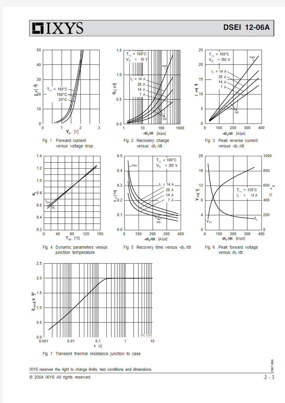
Fig. Forward current versus voltage drop
Fig. 2 Recovery charge
versus -di F /dt
Fig. 3 Peak reverse current versus -di F /dt
Fig. 4 Dynamic parameters versus junction temperature
Fig. 5 Recovery time versus -di F /dt
Fig. 7 T ransient thermal resistance junction to case
Fig. 6 Peak forward voltage
versus di F /dt
007 004
IXYS reserves the right to change limits, test conditions and dimensions.
Dimensions TO-220 AC