丹佛斯压缩机手册
- 格式:pdf
- 大小:398.58 KB
- 文档页数:4

丹佛斯VLT2800变频器操作说明丹佛斯VLT2800变频器操作说明1、引言本文档提供了丹佛斯VLT2800变频器的详细操作说明。
变频器是一种能够控制电机转速的设备,广泛应用于工业控制系统中。
本文档将介绍变频器的特性、安装步骤、参数设置、故障排除等内容。
2、变频器概述2.1 变频器的作用变频器是一种能够通过调整输入电源频率来控制电机转速的设备。
它可以帮助用户实现电机的精准调速,提高生产效率。
2.2 VLT2800变频器的特性丹佛斯VLT2800变频器是一款高性能的变频控制器,具有以下特点:- 宽电压输入范围,适应于不同的电源标准;- 多种通讯接口,方便与工控系统集成;- 支持多种电机控制方式,包括向量控制和矢量控制;- 内置多种保护功能,能够保证电机和设备的安全运行。
3、安装步骤3.1 变频器安装前的准备工作在安装变频器之前,需要进行以下准备工作:- 确保电源系统能够满足变频器的额定电压和电功率要求;- 根据操作手册的要求,选择适当的安装位置;- 确保安装环境符合变频器的工作要求,包括温度、湿度、通风等。
3.2 变频器的安装步骤根据操作手册的指引,按照以下步骤安装变频器:1、安装变频器的壳体,确保安装牢固;2、连接变频器的电源线和电机线,注意接线的正确性;3、进行接地连接,确保设备的安全运行;4、安装外部配件,如风扇、滤波器等。
4、参数设置4.1 基本参数设置根据实际需求,可以通过变频器的参数设置功能来调整一些基本参数,包括输入电压范围、输出频率范围、过载保护等。
4.2 高级参数设置除了基本参数外,还可以通过高级参数设置来优化变频器的性能。
例如,调整矢量控制的参数,使得电机的转速控制更加精准。
5、故障排除在使用过程中,可能会遇到一些故障情况,如电流过高、过载、短路等。
本章将介绍一些常见故障的排查方法,并提供解决方案。
附件:- VLT2800变频器操作手册(附件1)- VLT2800变频器安装图纸(附件2)法律名词及注释:- 变频器:Variable Frequency Drive,是一种能够通过调整输入电源频率来控制电机转速的设备。

丹佛斯压缩机的命名规则
丹佛斯压缩机的命名规则是基于该品牌的产品命名体系,旨在区分不同型号和规格的压缩机。
丹佛斯是一家全球知名的压缩机制造商,其产品使用一套独特的命名规则,便于用户准确地选择和识别所需的压缩机。
首先,丹佛斯压缩机的命名包括一系列字母和数字,每个字母和数字都代表特定的信息。
其中,产品型号的第一个字母标识了产品系列。
例如,字母"H"可能代表家用压缩机,而字母"C"可能代表商用压缩机。
接下来的几个字母和数字表示产品的特定规格和性能。
例如,一些字母可能代表压缩机的制冷剂类型,如"R"代表制冷剂R-134a。
数字可能代表压缩机的制冷能力、电压要求或其他规格。
此外,丹佛斯还使用一些特定的词汇来描述压缩机的特殊功能或应用领域。
例如,"Scroll"表示螺杆式压缩机,"Danfoss Turbocor"表示涡旋式压缩机。
丹佛斯的命名规则旨在为用户提供便利,通过字母和数字的组合快速识别和理解压缩机的性能和规格。
这有助于用户选择最适合其需求的产品,并确保正确安装和运行压缩机。
总而言之,丹佛斯压缩机的命名规则是基于字母、数字和特定词汇的组合,旨在区分不同型号和规格的压缩机。
这些命名规则使用户能够快速准确地选择和使用丹佛斯压缩机。

MAKING MODERN LIVING POSSIBLE特点y y介质:淡水和中性盐水(按客户要求的海水类型)yy y制冷剂:HCFC y和不可燃y HFC yy y无需电源——自力式yy y在冷凝压力上升时打开yy 1.4 – 300 立方米/小时的完整流量范围yy y低流量型的WVFX – 0,63 立方米/小时y(按客户要求)yy y对灰尘不敏感yy WVFX 10 – 40 直接驱动水阀yy WVS 32 – 100 强制伺服操作水阀y y y根据客户需求,阀门可配有毛细管技术手册水阀WVFX 和 WVS 型WVFX y和y WVS型水阀用于调节带有水冷冷凝器的制冷装置中的水流量。
这些水阀可调整冷凝压力,并且在制冷装置的整个工作过程中维持其恒定。
当制冷装置停止运行时,冷却水供水自动关闭。
除了标准型号以外,可提供用于海水冷却的冷凝器和压缩机使用的采用不锈钢阀体,可用于腐蚀性液体的WVFX 15、WVFX 20 和y WVFX 25型水阀。
参数表 水阀,WVFX 和 WVS 型技术参数1) k v值为水在通过阀的压差等于 1 bar时的流量,单位为[立方米/小时],密度ρ = 1000 千克/立方米。
2)完全打开阀则需要比使用压力范围为 3.5-16 bar的WVFX阀压力高y33%y的压力,3) WVFX 15、WVFX 20 和y WVFX 25型水阀可提供不锈钢阀体。
WVFX 10 – 40 为直接驱动调节阀yWVS 32 – 100 为伺服操作调节阀介质温度范围yWVFX 10 – 25: -25 – 130 °C yWVFX y32 – 40: -25 – 90 °C yWVS:y y-25 – 90 °C y如果一个WVS型调节器需要 1 - 10 bar y的开启压力差时,y必须更换阀的伺服弹簧。
见“订货”部分。
开启压力差yWVFX 10 – 25:yy最大 10 bar y WVFX 32 – 40:yy最大 10 bar y WVS 32 – 40:yy最小 0.5 bar:y y最大 4 bar y WVS 50 – 100:yy最小 0.3 bar;y y最大 4 bar y低于最大负荷的 20% 时,WVSy实际上将作为一个开关调节器。
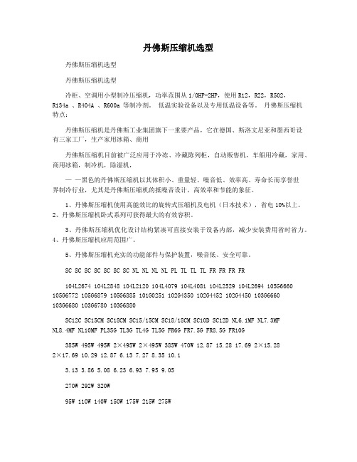
丹佛斯压缩机选型丹佛斯压缩机选型丹佛斯压缩机选型冷柜、空调用小型制冷压缩机,功率范围从1/0HP-2HP,使用R12,R22,R502,R134a 、R404A 、R600a 等制冷剂。
低温实验设备以及专用低温设备等。
丹佛斯压缩机特点:丹佛斯压缩机是丹佛斯工业集团旗下一重要产品,它在德国、斯洛文尼亚和墨西哥设有三家工厂,生产家用冰箱、商用丹佛斯压缩机目前被广泛应用于冷冻、冷藏陈列柜,自动贩售机,车船用冷藏,家用、商用冰箱,制冷机,除湿机,——黑色的丹佛斯压缩机以其体积小、重量轻、噪音低、效率高、寿命长而享誉世界制冷行业,尤其是丹佛斯压缩机的抵噪音设计,高效率和节能的象征。
1、丹佛斯压缩机使用高能效比的旋转式压缩机及电机(日本技术),省电10%以上。
2、丹佛斯压缩机卧式系列可获得最大的有效容积。
3、丹佛斯压缩机优化设计结构紧凑可直接安装于设备内部,减少安装费用省时省力。
4、丹佛斯压缩机应用范围广。
5、丹佛斯压缩机充实的功能部件与保护装置,噪音低、安全可靠。
SC SC SC SC SC SC SC NL NL NL NL PL TL TL TL FR FR FR FR104L2674 104L2848 104L2120 104L4079 104L4081 104L2529 104L2694 105G6660105G6772 105G6879 105G6885 101G0251 102G4350 102G4452 102G4450 103G6660103G6680 103G6780 103G6880SC12C SC15CM SC18CM SC15/15CM SC18/18CM SC10D SC12D NL6.1MF NL7.3MFNL8.4MF NL10MF PL35G TL3G TL4G TL5G FR6G FR7.5G FR8.5G FR10G385W 495W 495W 2×495W 2×495W 385W 470W 12.87 15.28 17.69 2×15.282×17.69 10.29 12.87 6.13 7.27 8.35 10.13.13 3.86 5.08 6.23 6.93 7.95 9.05270W 292W 320W95W 110W 140W 150W 175W 215W 275WFR SC SC SC SC SC TL FR FR FR NL SC SC SC SC SC SC SC SC SC SC SC SC SC SC FR SC SC 102U2071 103U2670 103U2790 103U2890 105F3710 104L2523 104L2623104L2697 104L2853 104L2854 104L2897 104L2123 104L2197 104L2195 104L2322104L2506 104L2606 104L2869 104L2139 103U2680 104L2525 104L2625 TL4CL FR6CLFR7.5CL FR8.5CL NL7CLX SC10CL SC12CL SC12CLX.2 SC15CL SC15CLX SC15CLX.2 SC18CL SC18LX.2 SC18LX.2 SC21CL SC10MLX SC12MLX SC15MLX SC18MLX FR6DL SC10DL SC12DL215W 235W 275W 235W 315W 385W590W 470W275W 385W 495W 103G6980 104G8000 104G8240 104G8520 104G8820 104G8140 FR11G SC10G SC12G SC15G SC18G SC21G 275W 250W 315W 385W 495W 550W 11.15 10.29 12.87 15.28 17.69 20.956.23 6.937.95 7.27 10.29 12.8720.95 10.29 12.87 15.28 17.68 6.23 10.29 12.87。

丹佛斯车载压缩机驱动器接线定义一、开场白嘿,朋友们!你有没有想过,我们日常乘坐的汽车中,有一个看似不起眼但却至关重要的部件——丹佛斯车载压缩机驱动器?这其中涉及到一个关键的概念,那就是接线定义。
就好比我们家里的电器需要正确接线才能正常工作一样,丹佛斯车载压缩机驱动器的接线也是有严格规定的。
那到底这接线定义是怎么一回事呢?今天咱们就来好好聊聊。
二、什么是丹佛斯车载压缩机驱动器接线定义?简单来说呀,丹佛斯车载压缩机驱动器接线定义就是规定了这个驱动器各个接线端口与外部线路连接的方式和规则。
比如说,咱们开车的时候,空调系统要正常运行,压缩机就得稳定工作,而这就依赖于驱动器的正确接线。
常见的一个误区就是,有人觉得接线随便接接就行。
其实不是这样的哦!在汽车的电气系统中,要确保每个部件都能协同工作,接线必须精准无误。
所以呢,只有按照规定的接线定义进行连接,丹佛斯车载压缩机驱动器才能正常发挥作用,保障汽车空调系统的稳定运行。
三、关键点解析3.1 核心特征或要素首先呢,接线端口的标识是一个重要的要素。
不同的端口有着特定的功能,比如电源输入端口、信号控制端口等等。
就像我们的手机充电接口,插错了可就充不了电。
丹佛斯车载压缩机驱动器的接线端口也一样,如果接错了,可能会导致驱动器无法正常启动,甚至损坏设备。
其次就是接线的类型和规格啦。
这可不是随便选的,要根据电流、电压等参数来确定。
就像我们建房子选钢材,得选能承受相应压力的规格,接线也是如此。
比如,某些高功率的线路就需要粗一些的导线,以保证电流的稳定传输。
最后就是接线的顺序和方法。
这就需要严格按照厂家的说明来操作。
比如说在连接多个线路时,先接哪根后接哪根都有讲究。
就像组装家具,步骤错了可能就装不起来。
只有按照正确的顺序和方法接线,才能确保丹佛斯车载压缩机驱动器正常工作。
3.2 容易混淆的概念丹佛斯车载压缩机驱动器接线定义很容易和普通电气接线混淆。
普通电气接线可能相对简单,要求没那么严格。

参数表ECL 舒适210及远程控制单元ECA30/311VD.KT.W1.02 © Danfoss 04/2010DEN-SMT/DK描述ECL210舒适系列ECL210舒适控制器:ECL210舒适控制器是一款属于ECL 家族中的电子气候补偿式温度控制器。
ECL 系列是应用于区域供热、中央空调的制热和制冷系统中的专用控制器。
ECL210最多可对3个回路进行控制,通过使用应用程序卡实现不同应用的选择。
它专为舒适温度,优化能源消耗而设计,通过ECL 应用程序卡(插入-运行)实现安装方便和用户友好的操作方式。
通过气候补偿,分时供热,对供水温度进行调节;通过一次网回水温度、流量和热量限制对供水温度进行优化,这些使节能变得更加容易。
控制器具备例如数据记录和报警等附加功能。
ECL 舒适210操作简单,可使用拨轮(多功能旋钮)或远程控制单元(RCU )。
拨轮和具有图形和文字菜单的显示界面可对用户进行引导。
ECL 舒适210控制器有可控硅输出对电动阀进行控制,继电器输出对循环泵/转换阀进行控制,或作为报警输出。
输入端最多可连接6个Pt1000温度传感器。
此外,2 个可配置输入可以被选择为Pt1000温度传感器,模拟输入(0—10 V)或数字量输入。
控制器可实现墙体或导轨安装。
ECL210B (无显示及操作拨轮)可安装于控制柜内,操作可通过安装于面板上的ECA30/31实现。
ECL210舒适控制器是一款独立控制器,但是可通过ECL 485总线与RCU 或ECL210/310进行通讯。
远程控制单元(RCU ):ECA30/31可对室内温度进行控制,通过4芯双绞线与ECL 控制器进行连接(由ECL485总线供电)。
ECA30/31有一个内置的室内温度传感器。
但可外接一个室内温度传感器,此时,内置的传感器失效。
ECA31还具有一个湿度传感器,在相关的应用程序中可被使用。
同一个ECL485总线中可最多连接2个RCU ;一个RCU 可最多连接10个ECL 控制器(主/从系统)。
VLT® AQUA 变频器操作说明目录目录1. 如何阅读这些操作说明3版权声明、责任限制和修订权利3认证3符号32. 安全性5一般警告5开始维修工作之前6特殊条件6避免意外启动7变频器安全停止(可选)7IT 主电源73. 简介9类型代码字符串104. 机械安装13开始之前13如何安装145. 电气安装23如何连接23主电源接线概述26如何连接电动机 - 前言31电动机接线概述32如何测试电动机和旋转方向。
376. 如何操作变频器45操作方式45如何操作图形化 LCP (GLCP)45如何操作数字式 LCP (NLCP)50提示与技巧557. 如何为变频器编程57如何设置57参数选项79默认设置790-** 操作/显示801-** 负载/电动机812-** 制动823-** 参考值/加减速834-** 极限/警告845-** 数字输入/输出856-** 模拟输入/输出868-** 通讯和选件879-** Profibus 8810-** CAN 现场总线8913-** 智能逻辑9014-** 特殊功能9115-** 变频器信息9216-** 数据读数9418-** 数据读数 29620-** FC 闭环9721-** 扩展闭环9822-** 应用功能9923-** 定时操作10125-** 多泵控制器10226-** 模拟输入/输出选件 MCB 10910329-** 水应用功能10431-** 旁路选件1058. 疑难解答107警告/报警列表1099. 规范113一般规范113特殊条件127索引132目录VLT ® AQUA 变频器操作说明1.1.1.1.版权声明、责任限制和修订权利本出版物含有 Danfoss 专有的信息。
. 用户接受和使用本手册,即表示用户同意仅将本文所含信息用于操作 Danfoss 设备,或者用于操作其他供应商提供的用于通过串行通讯线路同 Danfoss 设备通讯的设备。
加顿丹佛空压机说明书VB2000
1、压缩机在装入空调之前,应放在室内保管,不要风吹雨淋。
保管时的温度应控制在-10℃~+65℃范围内。
2、搬运时,请不要将压缩机横放或倒放。
这样做会使运动部件的润滑性能降低,以致压缩机起动时损坏泵体部件。
3、请注意,压缩机上的冲击负荷应控制在60G以下,此外压缩机的附件(储液器、箍带以及线盒盖)应避免受到冲击。
4、在设计时应保证空调到压缩机的配线有足够的长度以及保证压缩机有足够的摆设空间(自由度)。
5、压缩机的接线盒中有可能侵入水滴、垃圾以及灰尘时请注意进行适当的防湿以及防尘处理。
6、压缩机一般要在高温状态下运转,因此请使用不会在压缩机使用温度下发生劣化的电线。
7、请防止压缩机接触有吸湿性的材料以及接触腐蚀性气体与有机物,因为在上述情况下压缩机的外壳会受到腐蚀。
DKRCI.PS.RP0.D2.02 | 520H7653 | 1© Danfoss | DCS (ADAP-KOOL®) |2015-03Advantages• The evaporator is charged optimally – even when there are great variations of load and suction pressure.• Energy savings – the adaptive regulation of the refrigerant injection ensures optimum utilisation of the evaporator and hence a high suction pressure.• Exact temperature control – the combination of adaptive evaporator and temperaturecontrol ensures great temperature accuracy for the media.• The superheating is regulated to the lowest possible value at the same time as the media temperature is controlled by the thermostat function.The controller and valve can be used where there are requirements to accurate control of superheat and temperature in connection with refrigeration.E.g.:• Cold store (air coolers)• Processing plant (water chillers)•A/C plantUser Guide | Superheat controller, EKC 315A© Danfoss | DCS (ADAP-KOOL®) | 2015-03DKRCI.PS.RP0.D2.02 | 520H7653 | 2IntroductionFunctions• Regulation of superheat • Temperature control • MOP function• ON/OFF input for start/stop of regulation• Input signal that can displace the superheat reference or the temperature reference• Alarm if the set alarm limits are exceeded • Relay output for solenoid valve • PID regulation• Output signal following the temperature showing in the display SystemThe superheat in the evaporator is controlled by one pressure transmitter P and one temperature sensor S2.The valve can be one of the following types:• ICM• AKV (AKVA)ICM is an electronically, directly run engine valve, controlled by an ICAD type actuator. It is used with a solenoid valve in the liquid line.TQ valveThe controller can also control a TQ type valve. This valve has been discontinued from the product range, but the settings are still described in this manual.AKV is a pulsating valve.Where the AKV valve is used it also functions as solenoid valve.Temperature control is performed based on a signal from tem-perature sensor S3 which is placed in the air current before the evaporator. Temperature control is in the shape of an ON/OFFthermostat that shuts off the liquid flow in the liquid line.User Guide | Superheat controller, EKC 315A© Danfoss | DCS (ADAP-KOOL®) | 2015-03DKRCI.PS.RP0.D2.02 | 520H7653| 3OperationSuperheat functionYou may choose between two kinds of superheat, either:• Adaptive superheat or • Load-defined superheatMOPThe MOP function limits the valve’s opening degree as long as the evaporating pressure is higher than the set MOP value.Override functionVia the analog input a displacement can be made of the tempera-ture reference or of the superheat reference. The signal can either be a 0-20 mA signal or a 4-20 mA signal. The reference can be displaced in positive or negative direction.External start/stop of regulationThe controller can be started and stopped externally via a contact function connected to input terminals 1 and 2. Regulation is stopped when the connection is interrupted. The function must be used when the compressor is stopped. The controller then closes the solenoid valve so that the evaporator is not charged with refrigerant.RelaysThe relay for the solenoid valve will operate when refrigeration is required. The relay for the alarm function works in such a way that the contact is cut-in in alarm situations and when the controller is de-energised.Modulating/pulsating expansion valveIn 1:1 systems (one evaporator, one compressor and one condens-er) with small refrigerant charge ICM is recommended.In a system with an AKV valve the capacity can be distributed by up to three valves if slave modules are mounted. The controller will displace the opening time of the AKV valves, so that they will not pulsate at the same time.Used as slave module is a controller of the type EKC 347.Analog outputThe controller is provided with an analog current output which can be set to either 0-20 mA or 4-20 mA. The signal will either fol-low the superheat, opening degree of the valve or the air tem-perature.When an ICM valve is in use, the signal is used for control of the valve via the ICAD actuator.PC operationThe controller can be provided with data communication so that it can be connected to other products in the range of ADAP-KOOL® refrigeration controls. In this way operation, monitoring and data collection can be performed from one PC – either on the spot or ina service company.User Guide | Superheat controller, EKC 315ASurvey of functions© Danfoss | DCS (ADAP-KOOL®) | 2015-03DKRCI.PS.RP0.D2.02 | 520H7653 | 4User Guide | Superheat controller, EKC 315A © Danfoss | DCS (ADAP-KOOL®) | 2015-03DKRCI.PS.RP0.D2.02 | 520H7653| 5User Guide | Superheat controller, EKC 315A © Danfoss | DCS (ADAP-KOOL®) | 2015-03DKRCI.PS.RP0.D2.02 | 520H7653 | 6User Guide | Superheat controller, EKC 315A© Danfoss | DCS (ADAP-KOOL®) | 2015-03DKRCI.PS.RP0.D2.02 | 520H7653| 7User Guide | Superheat controller, EKC 315A© Danfoss | DCS (ADAP-KOOL®) | 2015-03DKRCI.PS.RP0.D2.02 | 520H7653 | 8There are LED’s on the front panel which will light up when the belonging relay is activated.The upper LED will indicate the valve’s opening degree. A short pulse indicates a small liquid flow and a long pulse a heavy liquid flow. The other LED will indicate when the controller calls for refrigeration.The three lowermost LED’s will flash, if there is an error in the regu-lation.In this situation you can upload the error code on the display and cancel the alarm by giving the uppermost button a brief push.DisplayThe values will be shown with three digits, and with a setting you OperationMenu surveyThe buttonsWhen you want to change a setting, the two buttons will give you a higher or lower value depending on the button you are push-ing. But before you change the value, you must have access to the menu. You obtain this by pushing the upper button for a couple of seconds - you will then enter the column with parameter codes. Find the parameter code you want to change and push the two buttons simultaneously. When you have changed the value, save the new value by once more pushing the two buttons simultane-ously. Gives access to the menu (or cutout an alarm) Gives access to changesSaves a changeExamples of operationsSet set-point1. Push the two buttons simultaneously2. Push one of the buttons and select the new value3. Push both buttons again to conclude the settingSet one of the other menus1. Push the upper button until a parameter is shown2. Push one of the buttons and find the parameter you want to change3. Push both buttons simultaneously until the parameter value is shown4. Push one of the buttons and select the new value5. Push both buttons again to conclude the settingSW =1.4xFunctionPara-meterMin.Max.FactorysettingNormal displayShows the actual superheat/ valve's opening degree/ temperature Define view in o17-KTemperature, superheating, or the temp. reference is displayed if the bottom button is pressed briefly.Define view in o17-%ReferenceSet the required set point --60°C 50°C 10Differentialr010.1 K 20 K 2.0Units (0=°C+bar /1=°F+psig)r05010External contribution to the reference r06-50 K50 K0Correction of signal from S2r09-50.0 K 50.0 K 0.0Correction of signal from S3r10-50.0 K 50.0 K 0.0Start / stop of refrigeration r12OFF On 0Define thermostat function(0= no thermostat function, 1=On/off thermostat)r141AlarmUpper deviation (above the temperature setting)A01 3.0 K 20 K 5.0Lower deviation (below the temperature setting)A02 1 K10 K3.0Alarm’s time delay A030 min.90 min.30Regulating parameters P: Amplification factor Kp n040.520 3.0I: Integration time Tn0530 s 600 s 120D: Differentiation time Td (0 = off)n060 s 90 s 0Max. value of superheat reference n09 2 K 50 K 6Min. value of superheat reference n10 1 K 12 K 4MOP (max = off)n110.0 bar 60 bar 60Period time (only when AKV/A valve is used)n13 3 s 10 s 6Stability factor for superheat control.Changes should only be made by trained staff n180105Damping of amplification around reference value Changes should only be made by trained staff n190.2 1.00.3Amplification factor for superheatChanges should only be made by trained staff n200.010.00.4Definition of superheat control 1=MSS, 2=LOADAPn21121Value of min. superheat reference for loads under 10%n221152Standby temperature when valve closed (TQ valve only)Changes should only be made by trained staff n260 K20 KStandby temperature when valve open (TQ valve only)Changes should only be made by trained staff n27-15 K 70 K 20Max. opening degreeChanges should only be made by trained staff n320100100Min. opening degreeChanges should only be made by trained staff n33100Miscellaneous Controller’s addresso03*0119-ON/OFF switch (service-pin message)o04*---Define valve and output signal:0: Off1: TQ. AO: 0-20 mA 2: TQ. AO: 4-20 mA 3: AKV, AO: 0-20 m 4: AKV, AO: 4-20 mA5: AKV, AO: EKC 347-SLAVE 6: ICM, AO: 0-20 mA / ICM OD%7: ICM, AO: 4-20 mA / ICM OD%o09070User Guide | Superheat controller, EKC 315A© Danfoss | DCS (ADAP-KOOL®) | 2015-03DKRCI.PS.RP0.D2.02 | 520H7653| 9Factory settingIf you need to return to the factory-set values, it can be done in this way:- Cut out the supply voltage to the controller- Keep both buttons depressed at the same time as you recon n ect the supply voltageThe controller can give the following messages:E1Error message Fault in controllerE11Valve’s actuator temperature outside its range E15Cut-out S2 sensor E16Shortcircuited S2 sensor E17Cut-out S3 sensor E18Shortcircuited S3 sensorE19The input signal on terminals 18-19 is outside the range.E20The input signal on terminals 14-15 is outside the range (P0 signal)A1Alarm messageHigh-temperature alarm A2Low-temperature alarm A11No refrigerant has been selectedDefine input signal on the analog input AIA:0: no signal,1: Temperature setpoint. 0-20 mA 2: Temperature setpoint. 4-20 mA3: Displacement of superheat reference. 0-20 mA 4: Displacement of superheat reference. 4-20 mA o104Set supply voltage frequency o1250 Hz60 HzSelect display for ”normal picture”(Display the item indicated in parenthesis by briefly pressing the bottom button) 1: Superheat (Temperature)2: Valve’s opening degree (Superheat)3: Air temperature (Temperature reference)o17131Manual control of outputs:OFF: no manual control1: Relay for solenoid valve: select ON 2: AKV/A output: select ON3: Alarm relay activated (cut out)o18off3OffWorking range for pressure transmitter – min. valueo20-1 bar 60 bar -1.0Working range for pressure transmitter – max. valueo21-1 bar60 bar 12(Setting for the function o09, only AKV and TQ)Set the temperature value or opening degree where the output signal must be minimum (0 or 4 mA)o27-70°C 160°C -35(Setting for the function o09, only AKV and TQ)Set the temperature value or opening degree where the output signal must be maximum (20 mA)o28-70°C 160°C 15Refrigerant setting1=R12. 2=R22. 3=R134a. 4=R502. 5=R717. 6=R13. 7=R13b1. 8=R23. 9=R500. 10=R503. 11=R114.12=R142b. 13=User defined. 14=R32. 15=R227. 16=R401A.17=R507. 18=R402A. 19=R404A. 20=R407C. 21=R407A. 22=R407B. 23=R410A. 24=R170. 25=R290. 26=R600. 27=R600a. 28=R744. 29=R1270. 30=R417A. 31=R422A. 32=R413A. 33=R422D. 34=R427A. 35=R438Ao300350ServiceTQ valve's actuator temperatureu04°C Reference of the valve's actuator temperature u05°C Analog input AIA (18-19)u06mA Analog output AO (2-5)u08mA Read status of input DI u10on/off Thermostat cut-in time u18min.Temperature at S2 sensor u20°C Superheatu21K Superheat referenceu22K Read AKV valve’s opening degree u24%Read evaporating pressure u25bar Read evaporating temperature u26°C Temperature at S3 sensor u27°C Temperature referenceu28°C Read signal at pressure transmitter input u29mA*) This setting will only be possible if a data communication module has been installed in the controller.User Guide | Superheat controller, EKC 315A© Danfoss | DCS (ADAP-KOOL®) | 2015-03DKRCI.PS.RP0.D2.02 | 520H7653 | 10Installation considerationsAccidental damage, poor installation, or site conditions, can give rise to malfunctions of the control system, and ultimately lead to a plant breakdown.Every possible safeguard is incorporated into our products to prevent this. However, a wrong installation, for example, could still present problems. Electronic controls are no substitute for normal, good engineering practice.Danfoss wil not be responsible for any goods, or plant compo-nents, damaged as a result of the above defects. It is the installer's responsibility to check the installation thoroughly, and to fit the necessary safety devices.Particular attention is drawn to the need for a “force closing” signal to controllers in the event of compressor stoppage, and to the requirement for suction line accumulators.Your local Danfoss agent will be pleased to assist with further advice, etc.Appendix 1Interaction between internal and external start/stop functions and active functions.Appendix 2Cable length for the TQ actuatorThe actuator must be supplied with 24 V a.c. ± 10%.To avoid excessive voltage loss in the cable to the actuator, use a thicker cable for large distances.Wire cross sectionCable lengthInternal Start/stop Off Off On On External Start/stop (DI)Off On Off On Refrigeration (DO2)Off OnTQ actuatorStandbytemperatureRegulatingExpansion valve relay Off On Temperature monitoring No Yes Sensor monitoring Yes Yes ICM Closed RegulatingThe two types of regulation for superheat are, as follows:Adaptive superheatRegulation is here based on the evaporator’s load by means of MSS search (MSS = lowest permissible superheat).(The superheat reference is lowered to the exact point where instability sets in).The superheat is limited by the settings for min.and max.super-heat.Load-defined superheatThe reference follows a defined curve.This curve is defined by three values: the closing value, the min. value and the max. value. These three values must be selected in such a way that the curve is situated between the MSS curve and the curve for average temperature difference ∆Tm (temperature difference between media temperature and evaporating temperature.Setting example = 4, 6 and 10 K).Start of controllerWhen the electric wires have been connected to the controller, the following points have to be attended to before the regulation starts:1. Switch off the external ON/OFF switch that starts and stops the regulation.2. Follow the menu survey on page 8, and set the various para-meters to the required values.3. Switch on the external switch, and regulation will start.If the superheating fluctuatesWhen the refrigerating system has been made to work steadily, the controller’s factory-set control parameters should in most cases provide a stable and relatively fast regulating system.If the system however fluctuates this may be due to the fact that too low superheat parameters have been selected:If adaptive superheat has been selected:Adjust: n09, n10 and n18.If load-defined superheat has been selected:Adjust: n09, n10 and n22.Alternatively it may be due to the fact that the set regulation parameters are not optimal.If the time of oscillation is longer than the integration time:(Tp> Tn, (Tnis, say, 240 seconds))1. Increase Tnto 1.2 times Tp2. Wait until the system is in balance again3. If there is still oscillation, reduce Kpby, say, 20%4. Wait until the system is in balance5. If it continues to oscillate, repeat 3 and 4If the time of oscillation is shorter than the integration time:(Tp< Tn, (Tnis, say, 240 seconds))1. Reduce Kpby, say, 20% of the scale reading2. Wait until the system is in balance3. If it continues to oscillate, repeat 1 and 2.4. Follow the actual room temperature or superheat on the display.(On terminals 2 and 5 a current signal can be transmitted which represents the display view. Connect a data collection unit, if applicable, so that the temperature performance can be followed).If the superheat has excessive underswing during start-upIf you regulate with valve type ICM or AKV:Adjust n22 a little bit up and/or n04 a little bit down.If you regulate with valve type TQ:Adjust n26 a littlle bit downList of literatureInstructions RI8GT (extract from this manual).Here you can see how controllers are mounted and programmed.Installation guide for extended operation RC8ACHere you can see how a data communication connection to ADAP-KOOL® Refrigeration control systems can be estab-lished.Danfoss can accept no responsibility for possible errors in catalogues, brochures and other printed material. Danfoss reserves the right to alter its products without notice. This also applies to products already on order provided that such alternations can be made without subsequential changes being necessary in specifications already agreed.All trademarks in this material are property of the respecitve companies. Danfoss and Danfoss logotype are trademarks of Danfoss A/S. All rights reserved.。