Enriques Surfaces and other Non-Pfaffian Subcanonical Subschemes of Codimension 3
- 格式:pdf
- 大小:346.49 KB
- 文档页数:24

非均相fenton催化新材料英文回答:Non-homogeneous Fenton catalytic materials have gained significant attention in recent years due to their excellent performance in various applications. These materials are characterized by their non-uniform distribution of active sites, which allows for enhanced catalytic activity and selectivity. One example of such a material is a heterogeneous Fenton catalyst composed of iron-based nanoparticles supported on a porous substrate.The unique structure of non-homogeneous Fenton catalytic materials provides several advantages over traditional homogeneous Fenton catalysts. Firstly, the non-uniform distribution of active sites ensures efficient utilization of the catalyst, leading to improved catalytic performance. This is because the active sites are more accessible to the reactants, promoting faster reaction rates. Secondly, the heterogeneous nature of thesematerials allows for easy separation and recovery of the catalyst from the reaction mixture, making them more sustainable and economically viable.In addition to their enhanced catalytic activity and selectivity, non-homogeneous Fenton catalytic materials also exhibit excellent stability and recyclability. This is particularly important for industrial applications where the catalyst needs to withstand harsh reaction conditions and be used repeatedly. The non-uniform distribution of active sites prevents catalyst deactivation and facilitates the regeneration of the active sites, ensuring long-term stability and recyclability.Furthermore, non-homogeneous Fenton catalytic materials can be tailored to specific applications by adjusting the composition, morphology, and surface properties of the catalyst. For example, the size and shape of the nanoparticles can be controlled to optimize the catalytic activity and selectivity. Additionally, the surface of the catalyst can be modified to enhance its stability and resistance to deactivation. These design parameters allowfor the development of highly efficient and selective catalysts for various reactions.中文回答:非均相Fenton催化新材料近年来受到了广泛关注,因为它们在各种应用中表现出优异的性能。

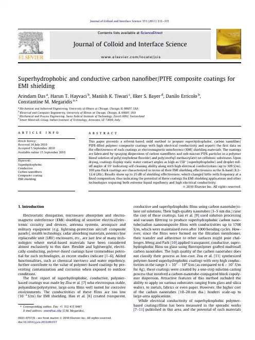
Superhydrophobic and conductive carbon nanofiber/PTFE composite coatings for EMI shieldingArindam Das a ,Harun T.Hayvaci b ,Manish K.Tiwari c ,Ilker S.Bayer d ,Danilo Erricolo b ,Constantine M.Megaridis a ,⇑aMechanical and Industrial Engineering,University of Illinois at Chicago,Chicago,IL 60607,USA bElectrical and Computer Engineering,University of Illinois at Chicago,Chicago,IL 60607,USA cMechanical and Process Engineering,Swiss Federal Institute of Technology,Zurich 8092,Switzerland dSmart Materials Group,Italian Institute of Technology,Arnesano,LE 73010,Italya r t i c l e i n f o Article history:Received 14July 2010Accepted 5September 2010Available online 15September 2010Keywords:Superhydrophobic ConductiveCarbon nanofibers Composite coating EMI shieldinga b s t r a c tThis paper presents a solvent-based,mild method to prepare superhydrophobic,carbon nanofiber/PTFE-filled polymer composite coatings with high electrical conductivity and reports the first data on the effectiveness of such coatings as electromagnetic interference (EMI)shielding materials.The coatings are fabricated by spraying dispersions of carbon nanofibers and sub-micron PTFE particles in a polymer blend solution of poly(vinyledene fluoride)and poly(methyl methacrylate)on cellulosic substrates.Upon drying,coatings display static water contact angles as high as 158°(superhydrophobic)and droplet roll-off angles of 10°indicating self-cleaning ability along with high electrical conductivities (up to 309S/m).100l m-thick coatings are characterized in terms of their EMI shielding effectiveness in the X-band (8.2–12.4GHz).Results show up to 25dB of shielding effectiveness,which changed little with frequency at a fixed composition,thus indicating the potential of these coatings for EMI shielding applications and other technologies requiring both extreme liquid repellency and high electrical conductivity.Ó2010Elsevier Inc.All rights reserved.1.IntroductionElectrostatic dissipation,microwave absorption and electro-magnetic interference (EMI)shielding of sensitive electrical/elec-tronic circuitry and devices,antenna systems,aerospace and military equipment (e.g.lightning-protection aircraft composite panels),stealth technology,radar absorbing materials,avionics line replaceable unit (LRU)enclosures,etc.,are just few of many tech-nologies where metal-based materials have been considered almost exclusively to this date.Flexible and lightweight,electri-cally-conducting,polymer-based coatings have tremendous poten-tial for such technologies,as recent studies indicate [1–6].Added functionalities,such as chemical inertness and water repellency,further contribute to the value of polymer-based coatings by pre-venting contamination and corrosion when exposed to outdoor conditions.The first report of superhydrophobic,conductive,polymer-based coatings was made by Zhu et al.[7]who electrospun stable,polyaniline/polystyrene,large-area films well suited for corrosive environments.The conductivities of these films are too low (10À2S/m)for EMI shielding.Han et al.[8]created transparent ,conductive and superhydrophobic films using carbon nanotube/si-lane sol solutions.Their high-quality nanotubes (3–5nm dia.)raise the cost of these coatings.Luo et al.[9]used solution processing and vacuum filtering to produce superhydrophobic carbon nano-tube/nafion nanocomposite films with conductivities up to 1700S/m,which were maintained even after 1000bending cycles.How-ever,since the films were formed on the filtration membranes,their transfer and adherence to other surfaces might pose chal-lenges.Meng and Park [10]applied transparent,conductive,super-hydrophobic films on glass using fluoropolymer grafted multiwall carbon nanotubes.The high quality of the carbon nanotubes does not classify their process as low-cost.Zou et al.[11]synthesized polymer-based superhydrophobic coatings with very high conduc-tivities in the range 3Â103À104S/m (as compared to 6Â107S/m for Ag);these coatings were created by a one-step solution casting process that involved a carbon-nanotube-conjugated block copoly-mer dispersion.Attractive features of this method included the ability to apply on various substrates ranging from glass and silica wafers,to metals,fabrics or even paper.However,the higher cost of the carbon nanotubes (10–20nm dia.)hinders scale-up to large-area applications.While electrical conductivity of superhydrophobic polymer-based coatings/films has been measured in the sporadic works [7–11]published in this area,and the potential of such materials0021-9797/$-see front matter Ó2010Elsevier Inc.All rights reserved.doi:10.1016/j.jcis.2010.09.017Corresponding author.Fax:+13124130447.E-mail address:cmm@ (C.M.Megaridis).has been mentioned[8,11]in conjunction with EMI shielding,no study exists on EMI shielding properties of super-repellent,poly-mer-basedfilms.Since the EMI shielding effectiveness of a material depends not only on its conductivity but also its permeability[4], EMI shielding does not correlate directly with conductivity.Fur-thermore,EMI shielding effectiveness varies with frequency[12], thus requiring EMI measurements to be performed over a fre-quency range or the entire spectrum,when necessary.In response to the need for defining the EMI shielding effectiveness of novel superhydrophobic and conductive,polymer-basedfilms,the pres-ent study examines water repellent,composite coatings comprising of carbon nanofiber/PTFEfillers dispersed in a hydrophobic poly-mer matrix and applied by spray.The work utilizes only solu-tion-processable,commercially available,raw materials,and is therefore inherently low-cost.Water droplet sessile contact angle, roll-off angle and electrical conductivity measurements are performed on coatings applied on glass microscope slides.EMI shielding measurements are performed over the range8.2–12.4GHz(X-band)on identical coatings applied on cellulosic paper substrates,which in their uncoated state,have typical thickness of $100l m.The underlying hypothesis is that coatings deposited on either glass or paper have similar properties and structure when applied under identical conditions.2.ExperimentalA solution blend of poly(vinylidenefluoride)(PVDF)and acrylic poly(methyl methacrylate)(PMMA)forms the composite polymer matrix,which has a good degree of hydrophobicity and interfacial adhesion properties.PVDF with its environmental durability, hydrophobicity and electroactivity,combined with its chemical inertness,is an ideal choice for the hydrophobic component in the binder polymer,while adhesion and particle dispersion is im-parted by the acrylic PMMA.PMMA on its own generally forms brittle coatings with much lower mechanicalflexibility and stress bearing capacity[13].Sub-micron PTFE particles are used as hydro-phobicfillers to tune the coating microstructure and reduce sur-face energy[14],whereas the electrical conductivity is manipulated using heat-treated,vapor-grown carbon nanofibers (CNFs)[15,16].To prepare the composite coatings,60/40wt.%solution blends of PVDF(530kDa;Sigma–Aldrich,USA)in Dimethylformamide (DMF)and PMMA(996kDa;Sigma–Aldrich,USA)in acetone were mixedfiFs(averagefiber dia.100nm,PR24XT-HHT Pyrog-raf III;Applied Sciences Inc.,USA)and sub-micron PTFE particles (average dia.260±54.2nm;Sigma–Aldrich,USA)in dispersions were added asfillers to create sprayable solutions which,after application on glass and cellulosic substrates,were heat-dried at 90°C for1.5h to remove any residual solvent.The CNFs are free of CVD carbon with highly graphitized structure developed by high temperature treatment,resulting in higher electrical and thermal conductivity compared to as-grownfibers[17].The composite films were superhydrophobic and had electrical conductivities spanning over six orders of magnitude for the following weight composition range:Polymer matrix/PTFE/CNF1/5.76/0.068-1.1.A more detailed description of the suspension preparation and coat-ing application is provided in Supplemental material section.The dried coating thickness was measured using an optical microscope calibrated for depth measurement(top vs.bottom of the coating).At least three different thickness measurements at different locations were performed on each sample to assess point-to-point thickness uncertainty.Typical coating thickness was near100l m.The electrical conductivity of the coatings ap-plied on glass slides was measured using a Keithley6517electrom-eter/ammeter and the two-probe method.The coating areas slated for contact with the measuring probes were coated with a conduc-tive silver paint to ensure good electrical contact.A Lab-view based program was used to generate I–V curves and extract the electrical resistance of the coatings,which was then used to determine con-ductivity using the measured values of the coating thickness,width and length.Electrical conductivity of the coatings rose with CNF loading.Water droplet contact and roll-off angle measurements were performed using an in house goniometer-type optical setup described previously[14].3.Results and discussionFig.1shows the results of wettability tests and conductivity measurements for composite coatings with different CNF loadings expressed in terms of CNF/polymer weight ratio.As shown in Fig.1a,static water contact angles for all CNF loadings remained above150°.At the maximum CNF loading of1.1,contact angle reached a value of158°.It is worth noting that the corresponding contact angle for CNF-free coating was158°(see Fig.S1),which indicates that super-repellency is not contingent on the presence of CNFs.As Fig.1b indicates,water droplet roll-off angles for all CNF loadings remained close or below10°,confirming the self-cleaning water repellent nature of these coatings.Self-cleaning is promoted by low roll-off angles when the water droplet carries impurities off the tilted surface.As expected,Fig.1a shows an increase in conductivity of the composite coatings with rising content of conductive CNFs.It can be seen that the electrical percolation threshold for the coatings falls within the0.068–0.138CNF loading range,which corresponds to CNF content of1–2wt.%.This range is well below the theoretical values calculated for spherical particlefillers[18].The reason for this difference is the high aspect ratio of CNFs[19].Thisfigure also delineates the required electrical conductivities for three different applications of conductive coatings using two horizontal lines[20]. EMI shielding requires the highest conductivity(top)band.Various electronic products require protection of their internal circuitry and magnetic memory based components(microchips or ICs)from interference of outside electromagneticfields.Materials with high-er values of conductivity can block incoming EM waves more effec-tively.On the other hand,for electrostatic dissipation(lowest band in Fig.1a),lower conductivities suffice to reduce charge accumula-tion on insulator surfaces to avoid damage through electrostatic discharge.As far as electrostatic painting is concerned,this is a pro-cess in which materials of moderate to high conductivity(middle band in Fig.1a)are deposited on substrates by electrostatic attrac-tion.Corrosion resistant and conductive lightweight polymer coat-ings in the automobile industry offer one such example.The conductivity values achieved by these coatings are above the elec-trostatic dissipation range and can reach into the EMI shielding range;metals can be painted using this process.It is clear from Fig.1a that CNF loading can be used as a tuning parameter to vary conductivity of the coatings by more thanfive orders of magnitude without compromising superhydrophobicity.A maximum conductivity value of309S/m was obtained for coat-ings with CNF loadings around1.This underscores the potential of such coatings for numerous applications,and especially EMI shielding.Fig.2shows scanning electron micrographs of the surface mor-phology of the composite coatings for the two extreme CNF load-ings studied(a–b0.068,c–d1.1).In both cases,good dispersion of PTFE particles and CNF was achieved within the polymer blend matrix.As mentioned earlier,more than15-fold increase in CNF loading did not alter the degree of superhydrophobicity of the coatings(see Fig.1a),although their surface morphology was al-tered from predominantly PTFE clustered spheres with some CNF312 A.Das et al./Journal of Colloid and Interface Science353(2011)311–315strands to a mix of PTFE spheres and nanofibers(compare Fig.2b and d).No phase separation or segregation of the particles is ob-served even for the highest CNF loading.Moreover,micro to nano-scale surface features are preserved in both cases.The main factor responsible for the good dispersion of PTFE and CNF,as well as the preservation of the rough surface features responsible for water repellency is the existence of the PVDF/PMMA polymer blend ma-trix.Individually,PVDF is a low-interfacial-energy inert polymer, hence particle dispersion within PVDF is rather e of pristine PMMA polymer,on the other hand,can result in coat-ings with brittle andflaky structure and morphology[21]although PMMA is compatible with thefiller particles due to its high inter-facial energy.To this end,the60/40PVDF/PMMA blend was found to be optimal for maintaining a good degree offiller dispersion and high hydrophobicity.The EMI shielding effectiveness of the coatings was measured through S parameter measurements in a two-port configuration [22](see Fig.S2)using an HP8719D vector network analyzer (VNA)with operating range50–13.5GHz.An in house assembly consisting of two opposing WR-90waveguides coupled together to fully encase one coated sample at a time was used to evaluate the EMI shielding performance of the coatings(Fig.S3).The capa-bility of a thin planar barrier(coating in the present case)to shield from electromagnetic waves is measured in terms of its signal attenuation,defined[23]as10logP iP t¼20log E iE t½dB ;ð1Þwhere P i is the incident power on one side of the barrier and P t is the power transmitted through the barrier to the other side.The power ratio may also be expressed in terms of the ratio of the magnitudes of the incident electricfield E i and transmitted electricfield E t by assuming that thefields are plane waves.Moreover,this same ratio can be expressed in terms of the ratio of voltages associated with the ports of an appropriate network,and thus be determined through S parameter measurements[24].In general,systems that carry electromagnetic waves may be given a simpler description by treating them as networks and focusing only on the exchange of electromagnetic energy at their ports.According to Eq.(1),whichconductivity and sessile water contact angle for various(PVDF+PMMA)/PTFE/CNF composite coatings as a function of CNF loading weight ratio.In all cases the PTFE/polymer weight ratio was5.76.The conductivity regimes suitable for different applications droplet roll-off angle on coatings with different CNF loadings.micrographs of(PVDF+PMMA)/PTFE/CNF coatings for the two extreme CNF loadings considered in this study(a,bmagnification)correspond to50l m;the ones in the right(high magnification)to2l m.(reflection)and S21(transmission),for coatings with different CNF loading in the8.2–12.4GHz frequency range(X-band), setup shown in Fig.S3.to1.1.An important outcome of the measurements drawn in Fig.3 is that both transmission and reflection parameters S11and S21re-main fairlyflat in the frequency range8.2–12.4GHz.This indicates that the present coatings are equally effective in shielding over this entire frequency range.4.ConclusionWe describe fabrication and characterization of superhydropho-bic,carbon nanofiber/PTFE-filled polymer composite coatings with high electrical conductivity.The polymer matrix was a PVDF/PMMA blend,which,even in the absence of particlefillers displayed a good degree of hydrophobicity,interfacial adhesion andflexibility.The electrical conductivity of the coatings was tuned by varying CNF loading,and reached up to309S/m without sacrificing self-clean-ing water repellent ability.We report thefirst measurements on EMI shielding effectiveness of superhydrophobic,conductive poly-mer-based coatings over the X-band(8.2–12.4GHz).Shielding val-ues as high as$25dB(with a corresponding transmission power of only$0.5%)were obtained for coating thickness under$100l m. Forfixed coating composition,the shielding level remained rela-tivelyflat over the entire frequency range considered herein.Our results indicate the potential of the present coatings not only for EMI shielding applications,but also for other technologies requiring extreme liquid repellency and high electrical conductivity simulta-neously.The synthesis method is attractive because it allows addi-tional functionalities,as required by specific applications,without sacrificing superhydrophobicity.AcknowledgmentsThe SEM characterization of the coatings was performed at the Imaging Technology Facility of UIUC.The EMI shielding measure-ments were performed at the Senior Design Lab of the Department of Electrical and Computer Engineering at UIC.Appendix A.Supplementary materialSupplementary data associated with this article can be found,in the online version,at doi:10.1016/j.jcis.2010.09.017.References[1]H.H.Kuhn,A.D.Child,W.C.Kimbrell,Towards Synth.Met.71(1995)2139.[2]P.Chandrasekhar,K.Naishadham,Synth.Met.105(1999)115.[3]D.D.L.Chung,Carbon39(2001)279.[4]Y.L.Yang,M.C.Gupta,K.L.Dudley,wrence,Nano Lett.5(2005)2134.[5]Y.Yang,M.C.Gupta,K.L.Dudley,Nanotechnology18(2007)345701.[6]S.Geetha,K.K.S.Kumar,C.R.K.Rao,M.Vijayan,D.C.Trivedi,J.Appl.Polym.Sci.112(2009)2073.[7]Y.Zhu,J.Zhang,Y.Zheng,Z.Huang,L.Feng,L.Jiang,Adv.Funct.Mater.16(2006)568.[8]J.T.Han,S.Y.Kim,J.S.Woo,G.W.Lee,Adv.Mater.20(2008)3724.[9]C.Luo,X.Zuo,L.Wang,E.Wang,S.Song,J.Wang,J.Wang,C.Fan,Y.Cao,Nanoletters8(2008)4454.[10]L.Y.Meng,S.J.Park,J.Colloid Interface Sci.342(2009)559.[11]J.Zou,H.Chen,A.Chunder,Y.Yu,Q.Huo,L.Zhai,Adv.Mater.20(2008)3337.[12]D.C.Trivedi,in:H.S.Nalwa(Ed.),Handbook of Organic Conductive Moleculesand Polymers,vol.2,Wiley,New York,1997,p.505.[13]Z.W.Wicks Jr.,F.N.Jones,S.P.Pappas,D.A.Wicks,Organic Coatings Science andTechnology,John Wiley&Sons,Hoboken,2007.[14]M.K.Tiwari,I.S.Bayer,G.M.Jursich,T.M.Schutzius,C.Megaridis,ACS Appl.Matr.Int.2(2010).[15]E.Hammel,X.Tang,M.Trampert,T.Schmitt,K.Mauthner,A.Eder,P.Potschke,Carbon42(2004)1153.[16]M.H.Al-Saleh,U.Sundararaj,Carbon47(2009)2.[17]S.Yang,K.Lozano,A.Lomeli,H.D.Foltz,R.Jones,Composites:Part A36(2005)691.[18]D.Stauffer,A.Aharony,Introduction to Percolation Theory,Taylor&Francis,Washington,DC,1992.[19]J.K.W.Sandler,J.E.Kirk,I.A.Kinloch,M.S.P.Shaffer,A.H.Windle,Polymer44(2003)5893.[20]R.Ramasubramaniam,J.Chen,H.Y.Liu,Appl.Phys.Lett.83(2003)2928.[21]I.S.Bayer,M.K.Tiwari,C.M.Megaridis,Appl.Phys.Lett.93(2008)173902.[22]Y.K.Hong,C.Y.Lee,C.K.Jeong,J.H.Sim,K.Kim,J.Joo,M.S.Kim,J.Y.Lee,S.H.Jeong,S.W.Byun,Curr.Appl.Phys.1(2001)439.[23]C.R.Paul,Introduction to Electromagnetic Compatibility,Hoboken,Wiley-Interscience,2006.[24]D.M.Pozar,Microwave Engineering,Hoboken,John Wiley&Sons,1998.A.Das et al./Journal of Colloid and Interface Science353(2011)311–315315。

专利名称:Residual Disinfectant Composition发明人:Amy L. Vanden Heuvel,Douglas R.Hoffman,Jeremy D. Paulsen,RebeccaVongsa,Paige N. Anunson,Lisa M. Kroll,CoreyT. Cunnington,David W. Koenig申请号:US15744091申请日:20150727公开号:US20180199567A1公开日:20180719专利内容由知识产权出版社提供摘要:A disinfectant composition that is capable of inactivating non-enveloped viruses as well as other microorganisms, such as gram negative and gram positive bacteria, fungi, parasites, enveloped viruses, etc., is provided. Through selective control over the nature of the acid(s) employed and the overall pH level, the present inventors have discovered that the composition can achieve rapid antiviral efficacy, particularly against non-enveloped viruses. Once applied to a surface (e.g., hard surface), the disinfectant composition forms a film that remains capable of providing residual antiviral activity. Notably, the present inventors have discovered that the use of a vinylpyrrolidone copolymer in combination with a polyquaternary ammonium polymer and cationic surfactant can have a synergistic effect on the stability of the film such that it can also achieve long-term, residual antiviral activity.申请人:Kimberly-Clark Worldwide, Inc.地址:Neenah WI US国籍:US更多信息请下载全文后查看。

elsevier目录[隐藏]【爱思唯尔公司】【爱思唯尔公司部门介绍】【爱思唯尔公司发展里程碑】【Elsev ier数据库】爱思唯尔企业标志[编辑本段]【爱思唯尔公司】Our mission:Elsevi er is an integral p artn er with th e scien tifi c,techni cal and h ealth co mmuni ties,delivering superior inf ormation produ cts and servi ces that foster co mmuni cation,build insigh ts,and enabl e indi vidual and collecti ve advan cemen t in sci enti fic research and health car e.Elsevi er.Building insigh ts.Br eaking bound aries.爱思唯尔致力于为全球三千多万科学家、研究人员、学生、医学以及信息处理的专业人士提供一流的信息产品和革新性的工具。
我们很荣幸能在全球科技和医学学术团体中扮演一个不可或缺的角色并为这些领域的发展尽绵薄之力,帮助科研人员和专业人士提高生产力和效率,同时不断投入并努力创新来更好地满足全球学术社区的需要。
Els ev ier公司沿用了Elzev ir 书屋的名字,并将Elzev ir 改为更为现代的书写方式Els ev ier。
数百年沧桑,Elsev ier 已从一家小小的致力于传播经典学术的荷兰书店发展为一个向全球科技和医学学术群体提供超过20,000本的刊物和图书的国际化多媒体出版集团。
公司标志:爱思唯尔公司的标志为一个长者手执缠绕于一棵大树的藤条。
其中长者象征广大的科技工作者,大树象征已经获得的科学知识,而藤条则象征科学知识与科技工作者之间的联系。

FREUND’S ADJUVANT, COMPLETE AND INCOMPLETEProduct Number F 5881 AND F 5506 Storage Temperature 2-8 °CProduct DescriptionAppearanceF 5881 Clear amber liquid containing particulate matter (dried cells)F 5506 Clear amber liquidFreund’s Adjuvant is one of the most commonly used adjuvants in research. It is used as a water-in-oil emulsion. It is prepared from non-metabolizable oils (paraffin oil and mannide monooleate). If it also contains killed Mycobacterium tuberculosis it is known as Complete Freund’s Adjuvant. Without the bacteria it is Incomplete Freund’s Adjuvant. First developed by Jules Freund in the 1940’s, Freund’s Adjuvant is designed to provide continuous release of antigens necessary for stimulating a strong, persistent immune response1,2,3 The main disadvantage of Freund’s Adjuvant is that it can cause granulomas, inflammation at the inoculation site and lesions. The mycobacteria in Complete Freund’s attracts macrophages and other cells to the injection site which enhances the immune response. For this reason, the Complete Freund’s Adjuvant is used for the initial injections. To minimize side-effects, Incomplete Freund’s Adjuvant is used for the boosts.For comparisons of different adjuvant systems, see references 4 and 5.ReagentsEach ml of F 5881 contains 1 mg of heat-killed and dried Mycobacterium tuberculosis (strain H37Ra, ATCC 25177), 0.85 ml paraffin oil and 0.15 ml of mannide monooleate.Each ml of F 5506 contains 0.85 ml of paraffin oil and 0.15 ml of mannide monooleate.Precautions and DisclaimerPlease consult the Material Safety Data Sheet for handling recommendations before working with this material.Storage/StabilityStore in a cooler at 2-8 °C. Do not Freeze.Procedure1. If using Complete Freund’s Adjuvant, vortex orshake to resuspend the Mycobacterium.2. Mix antigens (preferably in saline) with an equalvolume of the adjuvant to form an emulsion. Inorder to do this, vigorous and prolonged mixing isneeded. There are at least three methods whichcan be used to accomplish this:For small volumes the emulsion can be made in atube. Pipet the adjuvant in the tube first. Then,while vortexing, add an equal volume of the antigen solution. Vortex vigorously until a thick emulsionforms.For intermediate volumes, use two syringesconnected through a luer fitting. Ideally, a 3-wayvalve should be used. Take the desired amount ofantigen solution into a glass syringe. The volumeshould not fill more than half the syringe. Take anequal volume of the adjuvant into another glasssyringe. Remove all air and connect the syringesthrough the luer fitting to the 3-way valve. Adjustthe 3-way valve such that the connection is openbetween the two syringes. Carefully depress theplunger from the antigen solution first, pushing the antigen into the oil of the adjuvant. Alternately push the plungers, mixing the adjuvant and the antigensolution into an emulsion. Continue until theplungers are difficult to push.For large volumes, use a tissue homogenizer tomake the emulsion. Add the adjuvant to thehomogenizer first. Run the homogenizer for a short time to coat the inside with the adjuvant. Add anequal volume of the antigen solution and run until athick emulsion forms.3. The resulting emulsion should be very thick and adrop of it should not disperse if tested by placing on the surface of a saline solution.4. Transfer the emulsion to a syringe (or remove onesyringe from the luer fitting if using the two-syringe method). Remove all the air. Add an appropriatelysized needle. The samples are now ready forinjection.References1. Freund, J. and McDermott, K., Proc. Soc. Exp. Biol.Med., 49, 548-553 (1942)2. Freund, J., Ann. Rev. Microbiol., 1, 291 (1947)3. Freund, J., Adv. Tuberc. Res., 7, 130 (1956)4. Bennett, B. et al., J. Immuno. Meth., 153, 31-40(1992)5. Deeb, B.J. et al., J. Immuno. Meth., 152, 105-113(1992)6. Harlow, E. and Lane, D., Antibodies A LaboratoryManual, (Cold Spring Harbor Laboratory, 1988)alc 8/4/98Sigma brand products are sold through Sigma-Aldrich, Inc.Sigma-Aldrich, Inc. warrants that its products conform to the information contained in this and other Sigma-Aldrich publications. Purchaser must determine the suitability of the product(s) for their particular use. Additional terms and conditions may apply. Please see reverse side ofthe invoice or packing slip.。
CHAPTER1Introduction to Surface Plasmon ResonanceANNA J.TUDOS a AND RICHARD B.M.SCHASFOORT ba Shell Global Solutions International BV,P.O.Box380001030BN Amsterdam,The Netherlands;b Biochip Group,MESA+Institute for Nanotechnology,Biomedical Technology Institute(BMTI),Faculty of Science and Engineering,University of Twente,P.O.Box217,7500AE Enschede,The Netherlands1.1What is Surface Plasmon Resonance?Since itsfirst observation by Wood in1902[1,2],the physical phenomenon of surface plasmon resonance(SPR)has found its way into practical applications in sensitive detectors,capable of detecting sub-monomolecular coverage.What is surface plasmon resonance?Wood observed a pattern of‘‘anomalous’’dark and light bands in the reflected light,when he shone polarized light on a mirror with a diffraction grating on its surface.Physical interpretation of the phenomenon was initiated by Lord Rayleigh[3],and further refined by Fano[4],but a complete explanation of the phenomenon was not possible until1968,when Otto[5]and in the same year Kretschmann and Raether[6]reported the excitation of surface plasmons.Application of SPR-based sensors to biomolecular interaction mon-itoring wasfirst demonstrated in1983by Liedberg et al.[7].A historical overview of the use of the phenomenon for biosensor applications is given in Section1.3of this chapter.To understand the excitation of surface plasmons,let us start with a simple experiment.1.1.1A Simple ExperimentConsider the experimental set-up depicted in Figure1.1.When polarized light is shone through a prism on a sensor chip with a thin metalfilm on top,the light will be reflected by the metalfilm acting as a mirror.On changing the angle of incidence,and monitoring the intensity of the reflected light,the intensity of the1reflected light passes through a minimum (Figure 1.1,line A).At this angle of incidence,the light will excite surface plasmons,inducing surface plasmon resonance,causing a dip in the intensity of the reflected light.Photons of p-polarized light can interact with the free electrons of the metal layer,inducing a wave-like oscillation of the free electrons and thereby reducing the reflected light intensity.The angle at which the maximum loss of the reflected light intensity occurs is called resonance angle or SPR angle.The SPR angle is dependent on the optical characteristics of the system,e.g.on the refractive indices of the media at both sides of the metal,usually gold.While the refractive index at the prism side is not changing,the refractive index in the immediate vicinity of the metal surface will change when accumulated mass (e.g.proteins)adsorb on it.Hence the surface plasmon resonance conditions are changing and the shift of the SPR angle is suited to provide information on the kinetics of e.g.protein adsorption on the surface.1.1.2From Dip to Real-time MeasurementSurface plasmon resonance is an excellent method to monitor changes of the refractive index in the near vicinity of the metal surface.When the refractive index changes,the angle at which the intensity minimum is observed will shift as indicated in Figure 1.2,where (A)depicts the original plot of reflected light intensity vs.incident angle and (B)indicates the plot after the change in refractive index.Surface plasmon resonance is not only suited to measure the difference between these two states,but can also monitor the change in time,if one follows in time the shift of the resonance angle at which the dip is observed.A Angle (ϕ)BIntensity of reflected light(%) ϕFigure 1.1Schematic experimental set-up of surface plasmon resonance excitation.Asensor chip with a gold coating is placed on a hemisphere (or prism).Polarized light shines from the light source (star)on the sensor chip.Reflected light intensity is measured in the detector (disk).At a certainangle of incidence (j ),excitation of surface plasmons occurs,resulting in adip in the intensity of the reflected light (A).A change in refractive index atthe surface of the gold film will cause an angle shift from A to B.2Chapter 1Figure 1.2depicts the shift of the dip in time,a so-called sensorgram.If this change is due to a biomolecular interaction,the kinetics of the interaction can be studied in real time.SPR sensors investigate only a very limited vicinity or fixed volume at the metal surface.The penetration depth of the electromagnetic field (so-called evanescent field)at which a signal is observed typically does not exceed a few hundred nanometers,decaying exponentially with the distance from the metal layer at the sensor surface.The penetration depth of the evanescent field is a function of the wavelength of the incident light,as explained in Chapter 2.SPR sensors lack intrinsic selectivity:all refractive index changes in the evanes-cent field will be reflected in a change of the signal.These changes can be due to refractive index difference of the medium,e.g.a change in the buffer composition or concentration;also,adsorption of material on the sensor surface can cause refractive index changes.The amount of adsorbed species can be determined after injection of the original baseline buffer,as shown in Figure 1.2.To permit selective detection at an SPR sensor,its surface needs to be modified with ligands suited for selective capturing of the target compounds but which are not prone to adsorbing any other components present in the sample or buffer media.1.2How to Construct an SPR Assay?Now we have a basic understanding of the surface plasmon resonance signal and how to measure it in time.We know that the sensor surface needs to be modified to allow selective capturing and thus selective measurement of a target compound.AngleABTime (s)Figure 1.2A sensorgram:the angle at which the dip is observed vs.time.First,nochange occurs at the sensor and a baseline is measured with the dip at SPRangle (A).After injection of the sample (arrow)biomolecules will adsorb onthe surface resulting in a change in refractive index and a shift of the SPRangle to position B.The adsorption–desorption process can be followed inreal time and the amount of adsorbed species can be determined.3Introduction to Surface Plasmon ResonanceIn the following,we are going to learn more about an SPR measurement.First,the steps of an SPR assay will be discussed from immobilization through analysis to regeneration in a measurement cycle.Next,we get acquainted with a typical calibration curve,followed by examples of assay formats.Finally,a short outlook is provided on the basics of the instrumentation.1.2.1The Steps of an AssayIn the simplest case of an SPR measurement,a target component or analyte is captured by the capturing element or so-called ligand(Figure1.3).The ligand is permanently immobilized on the sensor surface previous to the measurement. Various sensor surfaces with immobilized ligands are commercially available, and many more can be custom-made,as explained in Chapters6and7.In the simplest case,the event of capturing the analyte by the ligand gives rise to a measurable signal,this is called direct detection.Figure1.4shows the sensor signal step-by-step in the measurement cycle with direct detection. Each measurement starts with conditioning the sensor surface with a suitable buffer solution(1).It is of vital relevance to have a reliable baseline before the capturing event starts.At this point,the sensor surface contains the active ligands,ready to capture the target analytes.On injecting the solution containingFlow of samplewith analyteBound ligand Y Figure1.3Schematic representation of direct detection:the analyte is captured by the ligands(Y)immobilized on the sensor surface.Accumulation of theanalyte results in a refractive index change in the evanescentfield shiftingthe SPR angle.Here the ligand is immobilized in a hydrogel.4Chapter1the analytes (2),they are captured on the surface.Also other components of the sample might adhere to the sensor surface;without a suitable selection of the ligand,this adherence will be non-specific,and thus easy to break.At this step,adsorption kinetics of the analyte molecule can be determined in a real-time measurement.Next,buffer is injected on to the sensor and the non-specifically bound components are flushed off(3).As indicated in the figure,the accumulated mass can be obtained from the SPR response (D R ).Also in this step,dissociation of the analyte starts,enabling the kinetics of the dissociation process to be studied.Finally,a regeneration solution is injected,which breaks the specific binding between analyte and ligand (4).If properly anchored to the sensor surface,the ligands remain on the sensor,whereas the target analytes are quantitatively removed.It is vital in order to perform multiple tests with the same sensor chip to use a regeneration solution which leaves the activity of the ligands intact,as the analysis cycle is required to take place repeatedly for hundreds,sometimes even thousands of times.Again,buffer is injected to condition the surface for the next analysis cycle.If the regeneration is incomplete,remaining accumulated mass causes the baseline level to be increased.Often SPR measurements are carried out to determine the kinetics of a binding process.For realistic results it is vital to prevent immobilization from Step:SPR-dipshift2. association 1. baseline3. dissociation4. regeneration 1. baseline Figure 1.4Sensorgram showing the steps of an analysis cycle:1,buffer is in contactwith the sensor (baseline step);2,continuous injection of sample solution(association step);3,injection of buffer (dissociation step);D R indicatesthe measured response due to the bound target compound;4,removal ofbound species from the surface during injection of regeneration solution(regeneration step)followed by a new analysis cycle.A bulk refractiveindex shift can be observed at t 1.See also page 222.5Introduction to Surface Plasmon Resonancechanging the ligand in a way that would influence its strength or affinity towards the target component.In addition,kinetic experiments can provide information on the thermodynamics,e.g.on the binding energy of processes.A description of the kinetic theory can be found in Chapter 4and examples of kinetic studies in Chapter 5.1.2.2Calibration CurveApart from kinetic and thermodynamic studies,SPR measurements can also be used for the determination of the concentration of the analyte in a sample (quantitative analysis).In this case,first different concentrations of the analyte are applied in separate analysis cycles.The sensorgrams measured at different concentrations give an overlay plot similar to that depicted in Figure 1.5,with the plateaus of the association step increasing at increasing analyte concentration [8].A calibration curve can be constructed by plotting the response (D R )after a certain time interval (t 1)versus concentration.When analyzing samples with an unknown concentration of the analyte,usually multiple dilutions are made,for example 10,100and 1000times,or for more accurate determinations serial dilutions by a factor of 2.If the concentrationRStep: 1. baseline 2. association 3. dissociation 4. regeneration 1. baseline Figure 1.5Typical overlay plot of sensorgrams from serial diluted analyte concen-trations.Just after injection at t 0a sample specific binding of the analyteoccurs and mass transport to the surface is rate limiting and linearlydependent on the concentration.From the slopes of a positive control(dR/dt),the concentration of an unknown sample can be determined.During the association phase the number of unbound ligand moleculesdecreases and dissociation takes place.The off-rate constant or dissocia-tion constant (k d )can be determined after injecting dissociation buffer att 1.See for more details chapter 4and 5of this book.6Chapter 1of the analyte in the sample is very high,the undiluted sample will yield results on the upper plateau range of the calibration curve.The diluted solutions,however, might yield points along the lower,concentration-dependent sections of the calibration curve and the concentration of the analyte can be determined.As mentioned above,SPR sensing means detection of refractive index changes at the sensor surface,which in practice translates to the amount of mass deposited at the sensor surface.Direct detection is only possible if the capturing event of the analyte brings about measurable refractive index changes.This is easier to achieve if the molecular weight of the analyte is high (i.e.around1000Da or higher).However,for small molecules to produce a measurable refractive index change,large numbers would be required,making the analysis intrinsically less sensitive.If the analyte is a small molecule (MW o1000Da),often direct detection is not viable.Detection of small molecules can be carried out using a different strategy. Most often,small molecules are detected in a sandwich,competition or inhi-bition assay format.In all assay formats,not only the lower detectable concentration is limited,but also the physical number of immobilized elements on the sensor surface,which provides a maximum limiting value.Discussion of the different assay formats can be found in Chapter7and other methods for concentration determination are described in Chapters4and5.1.2.3Determination of Kinetic ParametersThe most prominent benefit of direct detection using SPR biosensor technology is the determination of kinetics of(bio)molecular interactions.Reaction rate and equilibrium constants of interactions can be determined,e.g.the interac-tion A+B-AB can be followed in real time with SPR technology,where A is the analyte and B is the ligand immobilized on the sensor surface.Table1.1contains the most relevant kinetic parameters,the association and dissociation constants,for the simplest case A+B-AB.The association constant is the reaction rate of complex(AB)formation,giving the number of complexes formed per time at unit concentration of A and B.As soon as the complex AB is formed,its dissociation can commence.The dissociation rate constant describing this process expresses the number of AB complexes Table1.1Definitions of the most relevant kinetic parameters:the association and dissociation constants.Association rate constant,k a Dissociation rate constant,k d Definition A+B-AB AB-A+BDescription Reaction rate of ABformation:number of ABcomplexes formed perunit time at unitconcentration of A and B Dissociation rate of AB:number of AB complexesdissociating per unit timeUnits l molÀ1sÀ1sÀ1Typical range103–10710À1À5Â10À67Introduction to Surface Plasmon Resonancedissociating per unit time.Note that the unit dimensions for the association and dissociation rates are different and can vary with the stoichiometry of the complex.The typical range of the association and dissociation constant shows large variations and is dependent on,among other things,the temperature.When association of A and B starts,no product is yet present at the sensing surface.At this point,the rate of the association reaction is highest and that of the dissociation reaction is lowest.As the process progresses,more and more of the AB complex is produced,enhancing the rate of dissociation.Due to decreasing A and B concentration,the rate of association might decrease.Equilibrium is reached when the rates of the association and dissociation reactions are equal;the definitions and unit dimensions are given in Table 1.2.As can be seen,the equilibrium association and dissociation constants,which represent the affinity of an interaction,have a reciprocal relationship with each other.The effect of parameters such as temperature is described in later chapters.The rate constants (Table 1.1)and equilibrium constants (Table 1.2)of (bio)molecular interactions provide information on the strength of association and the tendency of dissociation.Various aspects of kinetics,models and calculation of affinity constants are described in Chapters 4,5and 9.1.2.4Basics of InstrumentationStudying biomolecular interactions using SPR does not require a detailed understanding of the physical phenomena.It is sufficient to know that SPR-based instruments use an optical method to measure the refractive index near a sensor surface (within B 200nm to the surface).SPR instruments comprise three essential units integrated in one system:optical unit,liquid handling unit and the sensor surface.The features of the sensor chip have a vital influence on the quality of the interaction measurement.The sensor chip forms a physical barrier between the optical unit (dry section)and the flow cell (wet section).SPR instrumentation can be configured in various ways to measure the shift of the SPR-dip.In general,three different optical systems (Chapter 2)are used to excite surface plasmons:systems with prisms,gratings and optical waveguides.Most widespread are instruments with a prism coupler,also called ‘‘Kretschmann configuration’’[9].In this configuration,which is shown in Figure 1.1,a prism couples p-polarized light into the sensor coated with a thin metal film.The light is Table 1.2Definition of the equilibrium association and dissociation constants.Equilibrium associationconstant,K A Equilibrium dissociation constant,K DDefinition [AB]/[A][B]¼k a /k d [A][B]/[AB]¼k d /k a Description Affinity to association:high K A ,high affinity to associate Stability of AB:high K D ,low stability of ABUnit l mol À1mol l À1Typical range 105–101210À5–10À128Chapter 1reflected on to a detector,measuring its intensity,using a photodiode or a camera.In instruments with a grating coupler [10],light is reflected at the lower refractive index substrate.In practice,this means that light travels through the liquid before photons generate surface plasmon waves as in ellipsometric instruments [11].Besides the grating couplers,some instruments apply optical waveguide couplers[12]or measure the SPR wavelength shift as a result of the biomolecular interaction process (see Chapter 2and ref.[13]).All configurations share the same intrinsic phenomenon:the direct,label-free and real-time measurement of refractive index changes at the sensor surface.SPR sensors offer the capability of measuring low levels of chemical and biological compounds near the sensor surface.Sensing of a biomolecular binding event occurs when biomolecules accumulate at the sensor surface and change the refractive index by replacing the background electrolyte.Protein molecules have a higher refractive index than water molecules (D n E 10À1).The sensitivity of most SPR instruments is in the range D n E 10À5or 1pg mm À2of proteinous material.Often in real-time biosensing absolute values are not a prerequisite,only the change is monitored as a result of biospecific interaction at the sensor surface.A detailed description of commer-cial instruments is given in Chapter 3.1.3History of SPR BiosensorsThe term biosensor was introduced around 1975,relating to exploiting trans-ducer principles for the direct detection of biomolecules at surfaces.Currently the most prominent example of a biosensor is the glucose sensor,reporting glucose concentration as an electronic signal,e.g.based on a selective,enzymatic process.Some argued that all small devices capable of reporting parameters of the human body were biosensors (e.g.ion-sensitive field-effect transistors (ISFETs)measur-ing pH).But then,a thermometer recording fever should also be called biosensor.According to the present definition,in biosensors the recognition element (ligand)of the sensor or the analyte should originate from a biological source.Biosensors are analytical devices comprised of a biological element (tissue,microorganism,organelle,cell receptor,enzyme,antibody)and a physicochemi-cal transducer.Specific interaction between the target analyte and the biological material produces a physico-chemical change detected by the transducer.The transducer then yields an analog electronic signal proportional to the amount (concentration)of a specific analyte or group of analytes.1.3.1Early History of SPR BiosensorsApplication of SPR-based sensors to biomolecular interaction monitoring was first demonstrated in 1983by Lundstrom’s pursuit towards physical 9Introduction to Surface Plasmon Resonance10Chapter1 methods for label-free,real-time detection of biomolecules[7].The intrinsic properties of the molecules,e.g.mass,refractive index and/or charge distri-bution[14],were probed using ellipsometry,refractometry,surface plasmon resonance,photothermic detection methods and others.At the National Defense Research Laboratory of Sweden,protein–protein interactions were monitored in real time,label-free,using ellipsometry.Most importantly,the refractive index change at a light-reflecting surface was the operating trans-ducer mechanism.Although successful in the detection of refractive index change due to the binding of biomolecules on optical transducer surfaces,a disadvantage of the ellipsometer is that light passes through the bulk of the sample solution,hence light-absorbing or particle-containing samples cannot easily be measured.Among other research laboratories in the same period,the University of Twente(The Netherlands)was active in the search forfinding new transduction principles for measuring immunochemical reactions atfield effect transistor devices(ImmunoFET)[15]and at surfaces with an optical read-out(immuno-chemical optical biosensor,IMOB).Optical transducer principles[16]including ellipsometry,surface plasmon resonance and interferometric principles(Mach Zehnder)showed promise for direct transduction of the biomolecular binding event.Successful measurements of immunochemical reactions using SPR were carried out as early as in the mid-1980s[17].Pharmacia Biosensor AB chose SPR as their platform technology for direct sensing of biomolecular interactions.The Kretschmann configuration offered advantages in freedom of design of the liquid handling ing from the higher refractive index medium(the prism),light does not pass through the liquid,but is reflected at the sensor surface covered with a thin metal layer. Gold was chosen as the best inert metalfilm required for surface plasmon resonance,although from a physical point of view silver provides a better SPR effect(see Chapter2).Studies on the surface chemistry led to modification of the gold with a self-assembling layer of long-chain thiols to which a hydrogel could be attached. Carboxylated dextran was immobilized at the surface,which provides a subst-rate for efficient covalent immobilization of biomolecules,in addition to a favorable environment for most biomolecular interactions.The thickness of the dextran hydrogel of100nm is perfectly compatible with the ca.200nm evanescentfield(see Figure1.3).The reliable production of these high-quality sensor chips was unequivocally the basis for the successful launch of SPR instruments.Techniques were developed to etch silica to form a casting mold for the manufacture of microfluidicflow channels.Also,development proceeded on optogels for use between the prism in the optical unit of the instrument and the sensor chip.The optogel ensures optical contact with the prism,allowing simple replacement of the sensor chip.These efforts in research and development relied on the combination of three unrelatedfields:optics,microfluidics and surface chemistry,and resulted in the successful development of the instrumental concept of biomolecular interaction analysis(BIA).1.3.2History of SPR Biosensors After 1990In 1990,Pharmacia Biosensor AB launched the first commercial SPR product,the Biacore instrument [18].The instrument was the most advanced,sensitive,accurate,reliable,reproducible direct biosensor technique and SPR became (and still is)the ‘‘golden standard’’of transducer principles for measuring real-time biomolecular interactions.Since the early 1990s,producers have been struggling to meet the standards set by Biacore.Fisons Instruments 1[19]made serious attempts to compete with Biacore’s technology;their cuvette-based IAsys instrument uses evanescent field-based technology,essentially not SPR,for the study of biomolecular interactions.The Biacore 2000instrument was introduced in 1994with improved detec-tion and a different flow system so that the sample could interact at four spots on the sensor.Data of the reference spot could be used for signal correction.With the introduction of Biacore 2000it also became possible to monitor directly interactions of small molecule analytes reacting with immobilized protein ligands [20].In 1995,the cuvette based SPR system of IBIS Technologies was launched.The instrument was compatible with the Biacore sensor chip.In 1997,the IBIS II,a two-channel cuvette-based SPR instrument with autosampler operation,was introduced [21].Following the merger with the sensor chip coating company Ssens BV in 1999,the development of an SPR imaging instrument was initiated at IBIS Technologies.In 2007,the development of the IBIS-iSPR instrument,with the scanning angle principle,resulted in the required reliability and accuracy for microarray imaging of multiple biomolecular interactions (4500).The potency of the instrument is demonstrated in Chapter 7.Biacore X,a two-spot instrument introduced in 1996,was followed by the Biacore 3000in 1998.The latter was later extended with recovery tools to improve interfacing with mass spectrometry [22].Biacore Q was introduced for the food analysis market in 2000(Chapter 11).Positioned for small molecule analysis and drug discovery,the introduction of the Biacore S51marked a technology shift in terms of detection,flow cell design and sample capacity:the area of the detected spot was reduced from 1to 0.01mm 2and the number of spots was increased from four to six.In 2004,a high-end instrument was introduced with four channels each with five sensor spots (Biacore A100).Combining the flow cell of the Biacore S51instrument and the performance of the four-channel Biacore 3000,this instrument has 20in-line sensors to monitor biomolecular interactions in the flow cells.The technology is not suitable,however,to image the surface.In Chapter 3,other Biacore instruments (T100and X100)are described.In order to measure up to 400interactions simulta-neously,in 2005Biacore acquired the grating coupler SPR system of HTS Biosystems,co-developed with Applied Biosystems (8500Affinity Analyzer),which was capable of imaging the sensor surface.After restyling,this product (named Flexchip)was launched in 2006[10].1Later Affinity Sensors.11Introduction to Surface Plasmon Resonance12Chapter1 Although it is impossible to describe accurately the history of the develop-ments of the25companies producing SPR(related)instruments(see Chapter3), it is justified to treat the history along the Biacore product line.During the years following the introduction of thefirst SPR instrument,detection sensi-tivity has improved by roughly20-fold.The range of affinity and kinetic data that can be determined has been extended at least100-fold as a consequence of the increased sensitivity and due to improvements in data analysis.The amount of independent sensor surfaces grew from four channels in1990(Biacore)to at least500in the new IBIS SPR imaging instrument.The carboxymethylated dextran surface introduced in1990[23],still thefirst choice for many applica-tions,has been complemented with a range of other surfaces.Systems for dedicated applications have been introduced by various manufacturers as complements to all-purpose research instrumentation[24].A good gauge of the success of biosensor technology is that more than1000publications each year include data collected from commercial biosensors.In the paper entitled ‘‘Survey of the2005commercial optical biosensor literature’’,Rich and Myszka [25]gave an outstanding overview of the SPR literature,including practical lessons in performing and interpreting biomolecular interaction analysis ex-periments.The majority of the publications(985)in2005employed Biacore technology(87%),indicating the relevance of Biacore’s technology in the market.Affinity Sensors was the runner-up company with40publications (B4%),Eco Chemie/Windsor Scientific(distributor)totaled18publications. which was essentially from the same technology provider(originally IBIS Technologies),Texas Instruments scored17publications in2005and60 publications(B6%)were attributed to13other companies.With the introduction of a number of new SPR instruments(Chapter3)and a series of novel sensor surfaces and chemistries,the impact of SPR biosensors on molecular interaction studies will continue to grow.With improved exper-imental design,including SPR imaging instruments and advanced data analysis methods,high-quality data for the determination of kinetic parameters of biomolecular interaction phenomena can be obtained.These data promise additional insights into the mechanisms of molecular binding events,which will be important for function–regulatory protein interaction studies in order to unravel the exciting processes in living species.1.4How to Read This BookAlthough most chapters can be read as stand-alone literature on different aspects of SPR technology,this handbook aims to provide the reader with a total coverage of the basics of the technique and applications and the most relevant developments at the time of reviewing.The book starts with a description of the physics of surface plasmons and SPR in its original form and some novel applications,for example,nanoparticle SPR.The description of SPR instrumentation and a survey of currently available commercial products from25companies follows in Chapter3.An introduction on how to obtain kinetic information from SPR measurements can be found in。

Conventional optical components rely on gradual phase shifts accumulated during light propagation to shape light beams. New degrees of freedom are attained by introducing abrupt phase changes over the scale of the wavelength. A two-dimensional array of optical resonators with spatially varying phase response and sub-wavelength separation can imprint such phase discontinuities on propagating light as it traverses the interface between two media. Anomalous reflection and refraction phenomena are observed in this regime in optically thin arrays of metallic antennas on silicon with a linear phase variation along the interface, in excellent agreement with generalized laws derived from Fermat’s principle. Phase discontinuities provide great flexibility in the design of light beams as illustrated by the generation of optical vortices using planar designer metallic interfaces. The shaping of the wavefront of light by optical components such as lenses and prisms, as well as diffractive elements like gratings and holograms, relies on gradual phase changes accumulated along the optical path. This approach is generalized in transformation optics (1, 2) which utilizesmetamaterials to bend light in unusual ways, achieving suchphenomena as negative refraction, subwavelength-focusing,and cloaking (3, 4) and even to explore unusual geometries ofspace-time in the early universe (5). A new degree of freedomof controlling wavefronts can be attained by introducingabrupt phase shifts over the scale of the wavelength along theoptical path, with the propagation of light governed byFermat’s principle. The latter states that the trajectory takenbetween two points A and B by a ray of light is that of leastoptical path, ()B A n r dr ∫r , where ()n r r is the local index of refraction, and readily gives the laws of reflection and refraction between two media. In its most general form,Fermat’s principle can be stated as the principle of stationaryphase (6–8); that is, the derivative of the phase()B A d r ϕ∫r accumulated along the actual light path will be zero with respect to infinitesimal variations of the path. We show that an abrupt phase delay ()s r Φr over the scale of the wavelength can be introduced in the optical path by suitably engineering the interface between two media; ()s r Φr depends on the coordinate s r r along the interface. Then the total phase shift ()B s A r k dr Φ+⋅∫r r r will be stationary for the actual path that light takes; k r is the wavevector of the propagating light. This provides a generalization of the laws of reflection and refraction, which is applicable to a wide range of subwavelength structured interfaces between two media throughout the optical spectrum. Generalized laws of reflection and refraction. The introduction of an abrupt phase delay, denoted as phase discontinuity, at the interface between two media allows us to revisit the laws of reflection and refraction by applying Fermat’s principle. Consider an incident plane wave at an angle θi . Assuming that the two rays are infinitesimally close to the actual light path (Fig. 1), then the phase difference between them is zero ()()()s in s in 0o i i o t t kn d x d kn d x θθ+Φ+Φ−+Φ=⎡⎤⎡⎤⎣⎦⎣⎦ (1) where θt is the angle of refraction, Φ and Φ+d Φ are, respectively, the phase discontinuities at the locations where the two paths cross the interface, dx is the distance between the crossing points, n i and n t are the refractive indices of thetwo media, and k o = 2π/λo , where λo is the vacuumwavelength. If the phase gradient along the interface isdesigned to be constant, the previous equation leads to thegeneralized Snell’s law of refraction Light Propagation with Phase Discontinuities: Generalized Laws of Reflection and RefractionNanfang Yu ,1 Patrice Genevet ,1,2 Mikhail A. Kats ,1 Francesco Aieta ,1,3 Jean-Philippe Tetienne ,1,4 Federico Capasso ,1 Zeno Gaburro 1,51School of Engineering and Applied Sciences, Harvard University, Cambridge, Massachusetts 02138, USA. 2Institute for Quantum Studies and Department of Physics, Texas A&M University, College Station, Texas 77843, USA. 3Dipartimento di Fisica e Ingegneria dei Materiali e del Territorio, Università Politecnica delle Marche, via Brecce Bianche, 60131 Ancona, Italy. 4Laboratoire de Photonique Quantique et Moléculaire, Ecole Normale Supérieure de Cachan and CNRS, 94235 Cachan, France. 5Dipartimento di Fisica, Università degli Studi di Trento, via Sommarive 14, 38100 Trento, Italy.o n S e p t e m b e r 1, 2011w w w .s c i e n c e m a g .o r g D o w n l o a d e d f r o m()()sin sin 2o t t i i d n n dx λθθπΦ−= (2) Equation 2 implies that the refracted ray can have an arbitrary direction, provided that a suitable constant gradient of phase discontinuity along the interface (d Φ/dx ) is introduced. Note that because of the non-zero phase gradient in this modified Snell’s law, the two angles of incidence ±θi lead to different values for the angle of refraction. As a consequence there are two possible critical angles for total internal reflection, provided that n t < n i : arcsin 2to c i i n d n n dx λθπ⎛⎞Φ=±−⎜⎟⎝⎠ (3)Similarly, for the reflected light we have ()()sin sin 2o r i i d n dx λθθπΦ−= (4) where θr is the angle of reflection. Note the nonlinear relationbetween θr and θI , which is markedly different fromconventional specular reflection. Equation 4 predicts that there is always a critical incidence angle arcsin 12o c i d n dx λθπ⎛⎞Φ′=−⎜⎟⎝⎠ (5) above which the reflected beam becomes evanescent. In the above derivation we have assumed that Φ is a continuous function of the position along the interface; thus all the incident energy is transferred into the anomalous reflection and refraction. However because experimentally we use an array of optically thin resonators with sub-wavelength separation to achieve the phase change along the interface, this discreteness implies that there are also regularly reflected and refracted beams, which follow conventional laws of reflection and refraction (i.e., d Φ/dx =0 in Eqs. 2 and 4). The separation between the resonators controls the relative amount of energy in the anomalously reflected and refracted beams. We have also assumed that the amplitudes of the scattered radiation by each resonator are identical, so that the refracted and reflected beams are plane waves. In the next section we will show by simulations, which represent numerical solutions of Maxwell’s equations, how indeed one can achieve the equal-amplitude condition and the constant phase gradient along the interface by suitable design of the resonators. Note that there is a fundamental difference between the anomalous refraction phenomena caused by phase discontinuities and those found in bulk designer metamaterials, which are caused by either negative dielectric permittivity and negative magnetic permeability or anisotropic dielectric permittivity with different signs ofpermittivity tensor components along and transverse to thesurface (3, 4).Phase response of optical antennas. The phase shift between the emitted and the incident radiation of an optical resonator changes appreciably across a resonance. By spatially tailoring the geometry of the resonators in an array and hence their frequency response, one can design the phase shift along the interface and mold the wavefront of the reflected and refracted beams in nearly arbitrary ways. The choice of the resonators is potentially wide-ranging, fromelectromagnetic cavities (9, 10), to nanoparticles clusters (11,12) and plasmonic antennas (13, 14). We concentrated on thelatter, due to their widely tailorable optical properties (15–19)and the ease of fabricating planar antennas of nanoscalethickness. The resonant nature of a rod antenna made of aperfect electric conductor is shown in Fig. 2A (20).Phase shifts covering the 0 to 2π range are needed toprovide full control of the wavefront. To achieve the requiredphase coverage while maintaining large scatteringamplitudes, we utilized the double resonance properties of V-shaped antennas, which consist of two arms of equal length h connected at one end at an angle Δ (Fig. 2B). We define twounit vectors to describe the orientation of a V-antenna: ŝalong the symmetry axis of the antenna and â perpendicular to ŝ (Fig. 2B). V-antennas support “symmetric” and “antisymmetric” modes (middle and right panels of Fig. 2B),which are excited by electric-field components along ŝ and â axes, respectively. In the symmetric mode, the current distribution in each arm approximates that of an individual straight antenna of length h (Fig. 2B middle panel), and therefore the first-order antenna resonance occurs at h ≈ λeff /2, where λeff is the effective wavelength (14). In the antisymmetric mode, the current distribution in each arm approximates that of one half of a straight antenna of length 2h (Fig. 2B right panel), and the condition for the first-order resonance of this mode is 2h ≈ λeff /2.The polarization of the scattered radiation is the same as that of the incident light when the latter is polarized along ŝ or â. For an arbitrary incident polarization, both antenna modes are excited but with substantially different amplitude and phase due to their distinctive resonance conditions. As a result, the scattered light can have a polarization different from that of the incident light. These modal properties of the V-antennas allow one to design the amplitude, phase, and polarization state of the scattered light. We chose the incident polarization to be at 45 degrees with respect to ŝ and â, so that both the symmetric and antisymmetric modes can be excited and the scattered light has a significant component polarized orthogonal to that of the incident light. Experimentally this allows us to use a polarizer to decouple the scattered light from the excitation.o n S e p t e m b e r 1, 2011w w w .s c i e n c e m a g .o r g Do w n l o a d e d f r o mAs a result of the modal properties of the V-antennas and the degrees of freedom in choosing antenna geometry (h and Δ), the cross-polarized scattered light can have a large range of phases and amplitudes for a given wavelength λo; see Figs. 2D and E for analytical calculations of the amplitude and phase response of V-antennas assumed to be made of gold rods. In Fig. 2D the blue and red dashed curves correspond to the resonance peaks of the symmetric and antisymmetric mode, respectively. We chose four antennas detuned from the resonance peaks as indicated by circles in Figs. 2D and E, which provide an incremental phase of π/4 from left to right for the cross-polarized scattered light. By simply taking the mirror structure (Fig. 2C) of an existing V-antenna (Fig. 2B), one creates a new antenna whose cross-polarized emission has an additional π phase shift. This is evident by observing that the currents leading to cross-polarized radiation are π out of phase in Figs. 2B and C. A set of eight antennas were thus created from the initial four antennas as shown in Fig. 2F. Full-wave simulations confirm that the amplitudes of the cross-polarized radiation scattered by the eight antennas are nearly equal with phases in π/4 increments (Fig. 2G).Note that a large phase coverage (~300 degrees) can also be achieved using arrays of straight antennas (fig. S3). However, to obtain the same range of phase shift their scattering amplitudes will be significantly smaller than those of V-antennas (fig. S3). As a consequence of its double resonances, the V-antenna instead allows one to design an array with phase coverage of 2π and equal, yet high, scattering amplitudes for all of the array elements, leading to anomalously refracted and reflected beams of substantially higher intensities.Experiments on anomalous reflection and refraction. We demonstrated experimentally the generalized laws of reflection and refraction using plasmonic interfaces constructed by periodically arranging the eight constituent antennas as explained in the caption of Fig. 2F. The spacing between the antennas should be sub-wavelength to provide efficient scattering and to prevent the occurrence of grating diffraction. However it should not be too small; otherwise the strong near-field coupling between neighboring antennas would perturb the designed scattering amplitudes and phases.A representative sample with the densest packing of antennas, Γ= 11 µm, is shown in Fig. 3A, where Γ is the lateral period of the antenna array. In the schematic of the experimental setup (Fig. 3B), we assume that the cross-polarized scattered light from the antennas on the left-hand side is phase delayed compared to the ones on the right. By substituting into Eq. 2 -2π/Γ for dΦ/dx and the refractive indices of silicon and air (n Si and 1) for n i and n t, we obtain the angle of refraction for the cross-polarized lightθt,٣= arcsin[n Si sin(θi) – λo/Γ] (6) Figure 3C summarizes the experimental results of theordinary and the anomalous refraction for six samples with different Γ at normal incidence. The incident polarization isalong the y-axis in Fig. 3A. The sample with the smallest Γcorresponds to the largest phase gradient and the mostefficient light scattering into the cross polarized beams. We observed that the angles of anomalous refraction agree wellwith theoretical predictions of Eq. 6 (Fig. 3C). The same peak positions were observed for normal incidence withpolarization along the x-axis in Fig. 3A (Fig. 3D). To a good approximation, we expect that the V-antennas were operating independently at the packing density used in experiments (20). The purpose of using a large antenna array (~230 µm ×230 µm) is solely to accommodate the size of the plane-wave-like excitation (beam radius ~100 µm). The periodic antenna arrangement is used here for convenience, but is notnecessary to satisfy the generalized laws of reflection and refraction. It is only necessary that the phase gradient isconstant along the plasmonic interface and that the scattering amplitudes of the antennas are all equal. The phaseincrements between nearest neighbors do not need to be constant, if one relaxes the unnecessary constraint of equal spacing between nearest antennas.Figures 4A and B show the angles of refraction and reflection, respectively, as a function of θi for both thesilicon-air interface (black curves and symbols) and the plasmonic interface (red curves and symbols) (20). In therange of θi = 0-9 degrees, the plasmonic interface exhibits “negative” refraction and reflection for the cross-polarized scattered light (schematics are shown in the lower right insetsof Figs. 4A and B). Note that the critical angle for totalinternal reflection is modified to about -8 and +27 degrees(blue arrows in Fig. 4A) for the plasmonic interface in accordance with Eq. 3 compared to ±17 degrees for thesilicon-air interface; the anomalous reflection does not exist beyond θi = -57 degrees (blue arrow in Fig. 4B).At normal incidence, the ratio of intensity R between the anomalously and ordinarily refracted beams is ~ 0.32 for the sample with Γ = 15 µm (Fig. 3C). R rises for increasingantenna packing densities (Figs. 3C and D) and increasingangles of incidence (up to R≈ 0.97 at θi = 14 degrees (fig.S1B)). Because of the experimental configuration, we are notable to determine the ratio of intensity between the reflected beams (20), but we expect comparable values.Vortex beams created by plasmonic interfaces. To demonstrate the versatility of the concept of interfacial phase discontinuities, we fabricated a plasmonic interface that isable to create a vortex beam (21, 22) upon illumination by normally incident linearly polarized light. A vortex beam hasa helicoidal (or “corkscrew-shaped”) equal-phase wavefront. Specifically, the beam has an azimuthal phase dependenceexp(i lφ) with respect to the beam axis and carries an orbitalonSeptember1,211www.sciencemag.orgDownloadedfromangular momentum of L l=h per photon (23), where the topological charge l is an integer, indicating the number of twists of the wavefront within one wavelength; h is the reduced Planck constant. These peculiar states of light are commonly generated using a spiral phase plate (24) or a computer generated hologram (25) and can be used to rotate particles (26) or to encode information in optical communication systems (27).The plasmonic interface was created by arranging the eight constituent antennas as shown in Figs. 5A and B. The interface introduces a spiral-like phase delay with respect to the planar wavefront of the incident light, thereby creating a vortex beam with l = 1. The vortex beam has an annular intensity distribution in the cross-section, as viewed in a mid-infrared camera (Fig. 5C); the dark region at the center corresponds to a phase singularity (22). The spiral wavefront of the vortex beam can be revealed by interfering the beam with a co-propagating Gaussian beam (25), producing a spiral interference pattern (Fig. 5E). The latter rotates when the path length of the Gaussian beam was changed continuously relative to that of the vortex beam (movie S1). Alternatively, the topological charge l = 1 can be identified by a dislocated interference fringe when the vortex and Gaussian beams interfere with a small angle (25) (Fig. 5G). The annular intensity distribution and the interference patterns were well reproduced in simulations (Figs. D, F, and H) by using the calculated amplitude and phase responses of the V-antennas (Figs. 2D and E).Concluding remarks. Our plasmonic interfaces, consisting of an array of V-antennas, impart abrupt phase shifts in the optical path, thus providing great flexibility in molding of the optical wavefront. This breaks the constraint of standard optical components, which rely on gradual phase accumulation along the optical path to change the wavefront of propagating light. We have derived and experimentally confirmed generalized reflection and refraction laws and studied a series of intriguing anomalous reflection and refraction phenomena that descend from the latter: arbitrary reflection and refraction angles that depend on the phase gradient along the interface, two different critical angles for total internal reflection that depend on the relative direction of the incident light with respect to the phase gradient, critical angle for the reflected light to be evanescent. We have also utilized a plasmonic interface to generate optical vortices that have a helicoidal wavefront and carry orbital angular momentum, thus demonstrating the power of phase discontinuities as a design tool of complex beams. The design strategies presented in this article allow one to tailor in an almost arbitrary way the phase and amplitude of an optical wavefront, which should have major implications for transformation optics and integrated optics. We expect that a variety of novel planar optical components such as phased antenna arrays in the optical domain, planar lenses,polarization converters, perfect absorbers, and spatial phase modulators will emerge from this approach.Antenna arrays in the microwave and millimeter-waveregion have been widely used for the shaping of reflected and transmitted beams in the so-called “reflectarrays” and “transmitarrays” (28–31). There is a connection between thatbody of work and our results in that both use abrupt phase changes associated with antenna resonances. However the generalization of the laws of reflection and refraction wepresent is made possible by the deep-subwavelengththickness of our optical antennas and their subwavelength spacing. It is this metasurface nature of the plasmonicinterface that distinguishes it from reflectarrays and transmitarrays. The last two cannot be treated as an interfacein the effective medium approximation for which one canwrite down the generalized laws, because they typicallyconsist of a double layer structure comprising a planar arrayof antennas, with lateral separation larger than the free-space wavelength, and a ground plane (in the case of reflectarrays)or another array (in the case of transmitarrays), separated by distances ranging from a fraction of to approximately one wavelength. In this case the phase along the plane of the array cannot be treated as a continuous variable. This makes it impossible to derive for example the generalized Snell’s lawin terms of a phase gradient along the interface. This generalized law along with its counterpart for reflectionapplies to the whole optical spectrum for suitable designer interfaces and it can be a guide for the design of new photonic devices.References and Notes1. J. B. Pendry, D. Schurig, D. R. Smith, “Controllingelectromagnetic fields,” Science 312, 1780 (2006).2. U. Leonhardt, “Optical conformal mapping,” Science 312,1777 (2006).3. W. Cai, V. Shalaev, Optical Metamaterials: Fundamentalsand Applications (Springer, 2009)4. N. Engheta, R. W. Ziolkowski, Metamaterials: Physics andEngineering Explorations (Wiley-IEEE Press, 2006).5. I. I Smolyaninov, E. E. Narimanov, Metric signaturetransitions in optical metamaterials. Phys. Rev. Lett.105,067402 (2010).6. S. D. Brorson, H. A. Haus, “Diffraction gratings andgeometrical optics,” J. Opt. Soc. Am. B 5, 247 (1988).7. R. P. Feynman, A. R. Hibbs, Quantum Mechanics andPath Integrals (McGraw-Hill, New York, 1965).8. E. Hecht, Optics (3rd ed.) (Addison Wesley PublishingCompany, 1997).9. H. T. Miyazaki, Y. Kurokawa, “Controlled plasmonnresonance in closed metal/insulator/metal nanocavities,”Appl. Phys. Lett. 89, 211126 (2006).onSeptember1,211www.sciencemag.orgDownloadedfrom10. D. Fattal, J. Li, Z. Peng, M. Fiorentino, R. G. Beausoleil,“Flat dielectric grating reflectors with focusing abilities,”Nature Photon. 4, 466 (2010).11. J. A. Fan et al., “Self-assembled plasmonic nanoparticleclusters,” Science 328, 1135 (2010).12. B. Luk’yanchuk et al., “The Fano resonance in plasmonicnanostructures and metamaterials,” Nature Mater. 9, 707 (2010).13. R. D. Grober, R. J. Schoelkopf, D. E. Prober, “Opticalantenna: Towards a unity efficiency near-field opticalprobe,” Appl. Phys. Lett. 70, 1354 (1997).14. L. Novotny, N. van Hulst, “Antennas for light,” NaturePhoton. 5, 83 (2011).15. Q. Xu et al., “Fabrication of large-area patternednanostructures for optical applications by nanoskiving,”Nano Lett. 7, 2800 (2007).16. M. Sukharev, J. Sung, K. G. Spears, T. Seideman,“Optical properties of metal nanoparticles with no center of inversion symmetry: Observation of volume plasmons,”Phys. Rev. B 76, 184302 (2007).17. P. Biagioni, J. S. Huang, L. Duò, M. Finazzi, B. Hecht,“Cross resonant optical antenna,” Phys. Rev. Lett. 102,256801 (2009).18. S. Liu et al., “Double-grating-structured light microscopyusing plasmonic nanoparticle arrays,” Opt. Lett. 34, 1255 (2009).19. J. Ginn, D. Shelton, P. Krenz, B. Lail, G. Boreman,“Polarized infrared emission using frequency selectivesurfaces,” Opt. Express 18, 4557 (2010).20. Materials and methods are available as supportingmaterial on Science Online.21. J. F. Nye, M. V. Berry, “Dislocations in wave trains,”Proc. R. Soc. Lond. A. 336, 165 (1974).22. M. Padgett, J. Courtial, L. Allen, “Ligh’'s orbital angularmomentum,” Phys. Today 57, 35 (2004).23. L. Allen, M. W. Beijersbergen, R. J. C. Spreeuw, J. P.Woerdman, “Orbital angular momentum of light and the transformation of Laguerre-Gaussian laser modes,” Phys.Rev. A, 45, 8185 (1992).24. M. W. Beijersbergen, R. P. C. Coerwinkel, M. Kristensen,J. P. Woerdman, “Helical-wavefront laser beams produced with a spiral phaseplate,” Opt. Commun. 112, 321 (1994).25. N. R. Heckenberg, R. McDuff, C. P. Smith, A. G. White,“Generation of optical phase singularities by computer-generated holograms,” Opt. Lett. 17, 221 (1992).26. H. He, M. E. J. Friese, N. R. Heckenberg, H. Rubinsztein-Dunlop, “Direct observation of transfer of angularmomentum to absorptive particles from a laser beam witha phase singularity,” Phys. Rev. Lett. 75, 826 (1995).27. G. Gibson et al, “Free-space information transfer usinglight beams carrying orbital angular momentum,” Opt.Express 12, 5448 (2004). 28. D. M. Pozar, S. D. Targonski, H. D. Syrigos, “Design ofmillimeter wave microstrip reflectarrays,” IEEE Trans.Antennas Propag. 45, 287 (1997).29. J. A. Encinar, “Design of two-layer printed reflectarraysusing patches of variable size,” IEEE Trans. AntennasPropag. 49, 1403 (2001).30. C. G. M. Ryan et al., “A wideband transmitarray usingdual-resonant double square rings,” IEEE Trans. AntennasPropag. 58, 1486 (2010).31. P. Padilla, A. Muñoz-Acevedo, M. Sierra-Castañer, M.Sierra-Pérez, “Electronically reconfigurable transmitarrayat Ku band for microwave applications,” IEEE Trans.Antennas Propag. 58, 2571 (2010).32. H. R. Philipp, “The infrared optical properties of SiO2 andSiO2 layers on silicon,” J. Appl. Phys. 50, 1053 (1979).33. R. W. P. King, The Theory of Linear Antennas (HarvardUniversity Press, 1956).34. J. D. Jackson, Classical Electrodynamics (3rd edition)(John Wiley & Sons, Inc. 1999) pp. 665.35. E. D. Palik, Handbook of Optical Constants of Solids(Academic Press, 1998).36. I. Puscasu, D. Spencer, G. D. Boreman, “Refractive-indexand element-spacing effects on the spectral behavior ofinfrared frequency-selective surfaces,” Appl. Opt. 39,1570 (2000).37. G. W. Hanson, “On the applicability of the surfaceimpedance integral equation for optical and near infraredcopper dipole antennas,” IEEE Trans. Antennas Propag.54, 3677 (2006).38. C. R. Brewitt-Taylor, D. J. Gunton, H. D. Rees, “Planarantennas on a dielectric surface,” Electron. Lett. 17, 729(1981).39. D. B. Rutledge, M. S. Muha, “Imaging antenna arrays,”IEEE Trans. Antennas Propag. 30, 535 (1982). Acknowledgements: The authors acknowledge helpful discussion with J. Lin, R. Blanchard, and A. Belyanin. Theauthors acknowledge support from the National ScienceFoundation, Harvard Nanoscale Science and EngineeringCenter (NSEC) under contract NSF/PHY 06-46094, andthe Center for Nanoscale Systems (CNS) at HarvardUniversity. Z. G. acknowledges funding from theEuropean Communities Seventh Framework Programme(FP7/2007-2013) under grant agreement PIOF-GA-2009-235860. M.A.K. is supported by the National ScienceFoundation through a Graduate Research Fellowship.Harvard CNS is a member of the NationalNanotechnology Infrastructure Network (NNIN). TheLumerical FDTD simulations in this work were run on theOdyssey cluster supported by the Harvard Faculty of Artsand Sciences (FAS) Sciences Division ResearchComputing Group.onSeptember1,211www.sciencemag.orgDownloadedfrom。
doi:10.1017/S1431927614002268© Microscopy Society of America 2014 Ex-situ and In-situ Analysis of MoVTeNb Oxide by Aberration-Corrected Scanning Transmission Electron MicroscopyPinghong Xu1, Maricruz Sanchez-Sanchez2, Andre C. Van Veen2, Nigel D. Browning3, Johannes A. Lercher2,31 Department of Chemical Engineering and Materials Science, University of California, Davis, Davis, USA.2 Department of Chemistry and Catalysis Research Center, Technische Universitat Munchen, 85748 Munich, Germany.3 Physical Sciences Laboratory, Pacific Northwest National Laboratory, 902 Battelle Boulevard, Richland, WA 99352, USA.Short chain olefins, especially ethylene and propylene are very important industrial raw materials and are of increasing demand worldwide. The abundance of C2-C3 light alkanes in shale gas makes production of these olefins from oxidative dehydrogenation (ODH) one of the most attractive alternatives to industrial processes [1]. Among all the catalysts for C2-C3 light alkane ODH reactions, the two-phase MoVTeNb oxide system has shown great promise [1]. Much attention has been devoted to the analysis of the crystallography structure of catalytic active M1 phase. However, the nature of the surfaces where the reactions take place and their roles in catalysis have not been resolved. Additionally, it has been reported that surfaces of the M1 phase undergo changes during ODH reactions, which would affect the catalytic activity of the system [2]. Therefore, it is also very important to perform the in situ experimental observations under relatively realistic conditions for a fundamental understanding of the outstanding catalytic performance of this material.Here, we report an identification of the nature of crystalline termination of the M1 phase at atomic scale using an aberration-corrected scanning transmission electron microscope (STEM). Figure 1 shows a typical M1 phase particle viewed in the crystal growth direction (the [001] orientation). Based on the analysis of over 50 particles, it is shown that the lateral surfaces of these rods are faceted and the most preferential lateral facets have been determined. The configuration of these facets means it is possible to quantify amount of ODH active sites exposed per area on each facet. Moreover, statistical analysis of the proposed active sites exposure in the M1 phase particles with different morphologies agrees very well with experimental data, showing a ~30% higher activity of the small rounded M1 phase rods compared to the large flattened ones. These results demonstrate that morphology has a large impact on catalytic activity of the MoVTeNb oxide system. Simulations are underway to determine the energies of those surface facets with slightly different configurations, which is essential for fundamental understanding of termination mechanism of material of such complex structures.Direct imaging of structural changes in the M1 phase was performed under an oxidative atmosphere by in-situ TEM technique using a Protochip heating holder in an environmental TEM. An M1 phase particles was heated to 350 °C in 10 mbar oxygen/argon (23%/77%) showed that tellurium units disappeared from hexagonal channels while the crystal framework remained unaffected. Control experiments with sample heated to the same temperature without oxygen showed no such effects. The crystalline structure was damaged within seconds. These results indicate that oxygen stabilizes the MoVTeNb oxide structure at elevated temperature. Further in-situ experiments using a gas stage holderwhich allows much higher partial pressure (above 1 bar) are underway to investigate the gas pressure effects [3].References:[1] F. Cavani et al., Catalysis Today 127 (2007), 113-131.[2] M. Hävecker et al.,Journal of Catalysis 285 (2012) 48–60[3] This work is supported by the U.S. Department of Energy Grant No. DE-FG02-03ER46057. The research described in this paper is part of the Chemical Imaging Initiative at PNNL under Contract DE-AC05-76RL01830 operated for DOE by Battelle. It was conducted under the Laboratory Directed Research and Development Program at PNNL, a multiprogram national laboratory operated by Battelle for the U.S. Department of Energy. A portion of the research was performed using EMSL, a national scientific user facility sponsored by the Department of Energy’s Office of Biological and Environmental Research and located at Pacific Northwest National Laboratory.Figure 1. (A) Unprocessed STEM image showing nicely crystalline and faceted surface of M1 phase. (B-D) Magnified view of rectangular areas 1-3 in (A) respectively, showing different facets configurations.。


使用加固纤维聚合物增强混凝土梁的延性作者:Nabil F. Grace, George Abel-Sayed, Wael F. Ragheb摘要:一种为加强结构延性的新型单轴柔软加强质地的聚合物(FRP)已在被研究,开发和生产(在结构测试的中心在劳伦斯技术大学)。
这种织物是两种碳纤维和一种玻璃纤维的混合物,而且经过设计它们在受拉屈服时应变值较低,从而体现出伪延性的性能。
通过对八根混凝土梁在弯曲荷载作用下的加固和检测对研制中的织物的效果和延性进行了研究。
用现在常用的单向碳纤维薄片、织物和板进行加固的相似梁也进行了检测,以便同用研制中的织物加固梁进行性能上的比较。
这种织物经过设计具有和加固梁中的钢筋同时屈服的潜力,从而和未加固梁一样,它也能得到屈服台阶。
相对于那些用现在常用的碳纤维加固体系进行加固的梁,这种研制中的织物加固的梁承受更高的屈服荷载,并且有更高的延性指标。
这种研制中的织物对加固机制体现出更大的贡献。
关键词:混凝土,延性,纤维加固,变形介绍外贴粘合纤维增强聚合物(FRP)片和条带近来已经被确定是一种对钢筋混凝土结构进行修复和加固的有效手段。
关于应用外贴粘合FRP板、薄片和织物对混凝土梁进行变形加固的钢筋混凝土梁的性能,一些试验研究调查已经进行过报告。
Saadatmanesh和Ehsani(1991)检测了应用玻璃纤维增强聚合物(GFRP)板进行变形加固的钢筋混凝土梁的性能。
Ritchie等人(1991)检测了应用GFRP,碳纤维增强聚合物(CFRP)和G/CFRP板进行变形加固的钢筋混凝土梁的性能。
Grace等人(1999)和Triantafillou(1992)研究了应用CFRP薄片进行变形加固的钢筋混凝土梁的性能。
Norris,Saadatmanesh和Ehsani(1997)研究了应用单向CFRP薄片和CFRP织物进行加固的混凝土梁的性能。
在所有的这些研究中,加固的梁比未加固的梁承受更高的极限荷载。
专利名称:A coronary endoprosthesis and a methodfor its fabrication发明人:Borghi, Enzo申请号:EP95830103.8申请日:19950317公开号:EP0722700A2公开日:19960724专利内容由知识产权出版社提供专利附图:摘要:A stent for implantation in a coronary artery (1) is assembled from discrete modules (2) fashioned in a biocompatible material, each composed of two "C" shaped members joined at the ends by respective rectilinear and mutually parallel members (3a,3b); the individual modules are linked together by a single helicoid element (4), likewise fashioned in a biocompatible material, which is coiled around the rectilinear members (3a, 3b) in such a way as to effect a closure of the modules, disposed one alongside another, in a direction parallel with their longitudinal axis (X). The modules (2) and the helicoid element (4) are plastically deformable both in the radial and in the axial dimension, so that the surgeon can vary the axial distribution of the modules internally of the blood vessel (1) and modify the ultimate configuration of the helicoid element (4).申请人:X-TRODE S.r.l.,MEDICORP S.A.地址:Via dell'Arcoveggio, 70 I-40129 Bologna IT,5, Allée Pelletier-Doisy F-54603 Villers-les-Nancy FR国籍:IT,FR代理机构:Lanzoni, Luciano更多信息请下载全文后查看。
矿产资源开发利用方案编写内容要求及审查大纲
矿产资源开发利用方案编写内容要求及《矿产资源开发利用方案》审查大纲一、概述
㈠矿区位置、隶属关系和企业性质。
如为改扩建矿山, 应说明矿山现状、
特点及存在的主要问题。
㈡编制依据
(1简述项目前期工作进展情况及与有关方面对项目的意向性协议情况。
(2 列出开发利用方案编制所依据的主要基础性资料的名称。
如经储量管理部门认定的矿区地质勘探报告、选矿试验报告、加工利用试验报告、工程地质初评资料、矿区水文资料和供水资料等。
对改、扩建矿山应有生产实际资料, 如矿山总平面现状图、矿床开拓系统图、采场现状图和主要采选设备清单等。
二、矿产品需求现状和预测
㈠该矿产在国内需求情况和市场供应情况
1、矿产品现状及加工利用趋向。
2、国内近、远期的需求量及主要销向预测。
㈡产品价格分析
1、国内矿产品价格现状。
2、矿产品价格稳定性及变化趋势。
三、矿产资源概况
㈠矿区总体概况
1、矿区总体规划情况。
2、矿区矿产资源概况。
3、该设计与矿区总体开发的关系。
㈡该设计项目的资源概况
1、矿床地质及构造特征。
2、矿床开采技术条件及水文地质条件。