5 土木工程 外文翻译 外文文献 英文文献 混凝土应力实验
- 格式:doc
- 大小:178.00 KB
- 文档页数:12
专业资料英文原文:Building construction concrete crack ofprevention and processingAbstractThe crack problem of concrete is a widespread existence but againdifficult in solve of engineering actual problem, this text carried ona study analysis to a little bit familiar crack problem in the concreteengineering,and aim at concrete the circumstance put forward some prevention, processing measure.Keyword: Concrete crack prevention processingForewordConcrete's is 1 kind is anticipate by the freestone bone, cement,water and other mixture but formation of the in addition material ofquality brittleness not and all material.Because the concrete construction transform with oneself, control etc. a series problem, harden model of in the concrete existence numerous tiny hole,spirit cave and tiny crack, is exactly because these beginning start blemish ofexistence just make the concrete present one some not and all the characteristic of quality.The tiny crack is a kind of harmless crack and accept concrete heavy, defend Shen and a little bit other use functionnot a creation to endanger.But after the concrete be subjected to lotus carry,difference in temperature etc.function,tiny crack wouldcontinuously of expand with connect, end formation we can see without the aid of instruments of macro view the crack be also the crack that theconcrete often say in the engineering.Concrete building and Gou piece usually all take sewer to make of,because of crack of existence and development usually make inner part of reinforcing bar etc. material creation decay, lower reinforced concretematerial of loading ability, durable and anti- Shen ability, influencebuilding of external appearance,service life,severity will threat arrive people's life and property safety. A lot of all of crash of engineerings is because of the unsteady development of the crack with the result that. Modern age science research with a great deal of of theconcrete engineering practice certificate, in the concrete engineeringcrack problem is ineluctable, also acceptable in certainly of the scopejust need to adopt valid of measure will it endanger degree control atcertain of scope inside. The reinforced concrete norm is also explicitprovision: Some structure at place of dissimilarity under the conditionallow existence certain the crack of width. But at under constructionshould as far as possible adopt a valid measure control crack creation,make the structure don't appear crack possibly or as far as possibledecrease crack of amount and width,particularly want to as far as possible avoid harmful crack of emergence, insure engineering quality thus.Concrete crack creation of the reason be a lot of and have alreadytransformed to cause of crack: Such as temperature variety,constringency, inflation, the asymmetry sink to sink etc. reason cause of crack; Haveoutside carry the crack that the function cause; Protected environment not appropriate the crack etc. caused with chemical e ffect.Want differentiation to treat in the actual engineering, workout a problemaccording to the actual circumstance.In the concrete engineering the familiar crack and the prevention1.Stem Suo crack and preventionStem the Suo crack much appear after the concrete protect be overof a period of time or concrete sprinkle to build to complete behind ofaround a week. In the cement syrup humidity of evaporate would creationstem Suo, and this kind of constringency is can't negative.Stem Suo crack of the creation be main is because of concrete inside outside humidityevaporate degree dissimilarity but cause to transform dissimilarity ofresult: The concrete is subjected to exterior condition of influence,surface humidity loss lead quick, transform bigger,inner part degree of humidity variety smaller transform smaller, bigger surface stem the Suotransform to be subjected to concrete inner part control, creation morebig pull should dint but creation crack. The relative humidity is morelow, cement syrup body stem Suo more big,stem the Suo crack be more easy creation. Stem the Suo crack is much surface parallel lines form or thenet shallow thin crack,mm, the flat surfacepart much see in the big physical volume concrete and follow it more inthinner beam plank short to distribute.Stem Suo crack usually the anti-Shen of influence concrete,cause the durable of the rust eclipse influence concrete of reinforcing bar, under the function of the waterpressure dint would creation the water power split crack influence concrete of loading dint etc..Concrete stem the Suo be main with waterash of the concrete ratio,the dosage of the composition,cement of cement, gather to anticipate of the dosage of the property and dosage, in addition etc. relevant.Main prevention measure: While being to choose to use the constringency quantity smaller cement, general low hot water mire andpowder ash from stove cement in the adoption,lower the dosage of cement. Two is a concrete of stem the Suo be subjected to water ash ratio ofinfluence more big, water ash ratio more big, stem Suo more big, so inthe concrete match the ratio the design should as far as possible control good water ash ratio of choose to use, the Chan add in the meantime accommodation of reduce water.Three is strict control concrete mix blend with under construction of match ratio, use of concrete water quantityabsolute can't big in match ratio design give settle of use water quantity. Four is the earlier period which strengthen concrete to protect, andappropriate extension protect of concrete time.Winter construction want to be appropriate extension concrete heat preservation to overlay time,and Tu2 Shua protect to protect.Five is a constitution the accommodation is in the concrete structure of the constringency sew.2.The Su constringency crack and preventionSu constringency is the concrete is before condense, surface because of lose water quicker but creation of constringency.The Su constringency crack is general at dry heat or strong wind the weather appear, crack'smuch presenting in the center breadth, both ends be in the center thinand the length be different, with each other not coherent appearance.Shorter crack general long 20-30 cm, the longer crack can reach to a 2-3m, breadth1-5mm. It creation of main reason is:The concrete is eventually almost having no strength or strength before the Ning verysmall, perhaps concrete just eventually Ning but strength very hour, besubjected to heat or compare strong wind dint of influence,the concrete surface lose water to lead quick, result in in the capillary creationbigger negative press but make a concrete physical volume sharply constringency, but at this time the strength of concrete again can'tresist its constringency,therefore creation cracked.The influence concrete Su constringency open the main factor of crack to have water ash ratio,concrete of condense time,environment temperature,wind velocity, relative humidity...etc..Main prevention measure: One is choose to use stem the Suo valuesmaller higher Huo sour salt of the earlier period strength or commontheHuo sour brine mire. Two is strict the control water ash ratio, the Chanadd to efficiently reduce water to increment the collapse of concrete fall a degree and with easy, decrease cement and water of dosage. Three is to sprinkle before building concrete, water basic level and template evento soak through. Four is in time to overlay the perhaps damp grass matof the plastics thin film, hemp slice etc., keep concrete eventuallybefore the Ning surface is moist, perhaps spray to protect etc. to carry on protect in the concrete surface. Five is in the heat and strong windthe weather to want to establish to hide sun and block breeze facilities, protect in time.3.Sink to sink crack and preventionThe creation which sink to sink crack is because of the structurefoundation soil quality not and evenly,loose soft or return to fill soil dishonest or soak in water but result in the asymmetry sink to declinewith the result that; Perhaps because of template just degree shortage,the template propped up to once be apart from big or prop up bottom loose move etc. to cause, especially at winter, the template prop up at jellysoil up, jelly the soil turn jelly empress creation asymmetry to sink to decline and cause concrete structure creation crack.This kind crack many is deep enter or pierce through sex crack, it alignment have somethingto do with sinking to sink a circumstance, general follow with groundperpendicular or present 30°s-45 °Cape direction development, biggersink to sink crack, usually have certain of wrong, crack width usuallywith sink to decline quantity direct proportion relation. Crack widthunder the influence of temperature variety smaller.The foundation after transform stability sink to sink crack also basic tend in stability.Main prevention measure: One is rightness loose soft soil, returnto fill soil foundation a construction at the upper part structure front should carry on necessity of Hang solid with reinforce.Twois the strength that assurance template is enough and just degree, and prop up firm,and makethe foundation be subjected to dint even. Three is keep concrete from sprinkle infusing the foundation in the process is soak by water. Fouris time that template tore down to can't be too early,and want to notice to dismantle a mold order of sequence. Five is at jelly soil top take toestablish template to notice to adopt certain of prevention measure.4.Temperature crack and preventionTemperature crack muchthe occurrence is in big surface or differencein temperature variety of the physical volume concrete compare the earth area of the concrete structure. Concrete after sprinkling to build, inthe hardening the process, cement water turn a creation a great deal ofof water turn hot, .(be the cement dosage is in the 350-550 kg/m 3, eachsign square the rice concrete will release a calories of 17500-27500 kJand make concrete internal thus the temperature rise to reach to 70℃or so even higher)Because the physical volume of concrete be more big,a great deal of of water turn hot accumulate at the concrete inner partbut not easy send forth, cause inner part the temperature hoick,but the concrete surface spread hot more quick, so formation inside outside ofbigger difference in temperature, the bigger difference in temperatureresult in inner part and exterior hot the degree of the bulge cold Suo dissimilarity, make concrete surface creation certain of pull shoulddint.When pull should dint exceed the anti- of concrete pull strengthextreme limit,concrete surface meeting creation crack, this kind of crack much occurrence after the concrete under construction the concrete of under construction be difference in temperature variety more big, perhaps is a concrete to be subjected to assault of cold wave etc.,will cause concrete surface the temperature sharply descend,but creation constringency, surface constringency of the concrete be subjected toinner part concrete of control,creation very big of pull should dint but creation crack, this kind of crack usually just in more shallow scope of the concrete surface creation.The alignment of the temperature crack usually none settle regulation, big area structure the crack often maneuver interleave;The size biggerstructure of the beamplank length, the crack run parallel with short side more;Thorough with pierce through sex of temperature crack general andshort side direction parallelism or close parallelism, crack along longside cent the segment appear, in the c enter width thesize be different, be subjected to temperature variety influence moreobvious,winter compare breadth,summer more narrow.The concrete temperature crack that the heat inflation cause is usually in the center the thick both ends be thin,but cold Suo crack of thick thin variety not too obvious.The emergence of the this kind crack will cause the rusteclipse of reinforcing bar,the carbonization of concrete,the anti-jelly which lower concrete melt, anti- tired and anti- Shen ability etc..Main prevention measure:One is as far as possible choose to use lowhot or medium hot water mire, like mineral residue cement,powder ash from stove cement...etc..Two is a decrease cement dosage, cement dosage as far as possible the control is in the 450 kg/m 3 following.Three is to lowerwater ash ratio, water ash of the general concrete ratio control below0.6.Four is improvement the bone anticipate class to go together with,the Chan add powder ash from stove or efficiently reduce water etc. tocome to reduce cement dosage and lower water to turn hot.Five is an improvement concrete of mix blend to process a craft, lower sprinkle ofconcrete to build temperature.Six is the in addition that the Chan adda have of fixed amount to reduce water and increase Su, slow Ning etc.function in the concrete, improvement the concrete mix to match a thingof mobility, protect water, lower water to turn hot, postpone hot Fengof emergence time.Seven is the heat season sprinkle to build can theadoption take to establish to hide sun plank etc. assistance measurecontrol concrete of WenSheng, lower to sprinkle temperature of build the is the temperature of big physical volume concrete should the dint relate to structure size, concrete structure size more big,temperature should dint more big,so want reasonable arrangement construction work preface, layering, cent the piece sprinkle to build,for the convenience of in spread hot,let is at great inner part constitution of the physical volume concrete cool off piping, coldwater perhaps cold air cool off,let up concrete of inside outside difference in is the supervision which strengthenis to reserve temperature constringency to sew.12 is to let up to control, sprinkle proper before building concrete in the Ji rock and old concrete top build a 5 mm or so sand mat a layer or usage asphalt etc. materialTu2 Shua.13 is to strengthen concrete to protect, the concrete aftersprinkle build use moist grass Lian in time, hemp slice's etc. overlay,and attention sprinkle water to protect, appropriate extension protecttime,assurance the concrete surface be slow-moving cool the cold season,concrete surface should constitution heat preservation measure, in order to prevent cold wave assault.14 is the allocation be a littleamount in the concrete of reinforcing bar perhaps add fiber materialconcrete of temperature crack control at certain of scope inside.5.Crack and prevention that the chemical reaction causeAlkali bone's anticipating the crack that reaction crack and reinforcing bar rust eclipse cause is the most familiar in the r einforced concrete structure of because of chemical reaction but cause of crack.The concrete blend a future reunion creation some alkalescence ion, these ion with some activity the bone anticipate creation chemical reaction and absorb surroundings environment in of water but the physical volume enlarge, make concrete crisp loose, inflation open crack.In thiskind of crack general emergence concrete structure usage period, onceappear very difficult remediable, so should at under construction adoptvalid the measure carry on prevention.Main of prevention measure:Whilebeing to choose to anticipate with the alkali activity small freestonebone.Two is the in addition which choose to use low lye mire with low alkaliis the Chan which choose to use accommodation with anticipate to repress an alkali bone to anticipate reaction.Because the concrete sprinkle to build, flap Dao bad perhaps is areinforcing bar protection layer thinner, the harmful material get intoconcrete to make reinforcing bar creation rust eclipse, the reinforcingbar physical volume of the rust eclipse inflation, cause concrete bulgecrack,the crack of this kind type much is a crack lengthways,follow the position of reinforcing bar of prevent measure from have:One is assurance reinforcing bar protection the thickness of thelayer.Two is a concrete class to go together with to want good.Three isa concrete to sprinkle to note and flap Dao airtight solid.Four is areinforcing bar surface layer Tu2 Shua antisepsis coating.Crack processingThe emergence of the crack not only would influence structure of whole with just degree,return will cause the rust eclipse of reinforcing bar, acceleration concrete of carbonization,lower durable and anti-of concrete tired, anti- Shen ability.Therefore according to the propertyof crack and concrete circumstance we want differentiation to treat, intime processing, with assurance building of safety usage.The repair measure of the concrete crack is main to have the following somemethod:Surface repair method, infuse syrup,the Qian sew method, the structure reinforce a method, concrete displacement method, electricity chemistry protection method and imitate to living from heal method.Surface repair the method be a kind of simple, familiar of repairmethod, it main be applicable to stability and to structure loading theability don't have the surface crack of influence and deep enter crackprocessing measure that is usually is a surface in crack daubery cement syrup, the wreath oxygen gum mire or at concrete surfaceTu2 Shua paint,asphalt etc.antisepsis material,at protection of in the meantime for keeping concrete from continue under the influence of various function to open crack, usually can adoption the surface in crack glueto stick glass fiber cloth etc. measure.1, infuse syrup, the Qian sew methodInfuse a syrup method main the concrete crack been applicable to have influence or have already defend Shen request to the structure whole ofrepair, it is make use of pressure equipments gumknot the material press into the crack of concrete, gum knot the material harden behind andconcrete formation one be whole, thus reinforce of purpose.The in common use gumknot material has the cement the syrup, epoxy, A Ji C Xi sour ester and gather ammonia ester to equalize to learn material.The Qian sew a method is that the crack be a kind of most in commonuse method in, it usually is follow the crack dig slot, the Qian fill Suin the slot or rigid water material with attain closing crack of purpose.The in commonuse Su material has PVCgummire, plastics ointment, the D Ji rubber etc.;In common use rigid water material is the polymercement sand syrup.2, the structure reinforce a methodWhenthe crack influence arrive concrete structure of function, will consideration adopt to reinforce a method to carry on processing to the concrete structure.The structure reinforce medium in commonuse main havethe following a few method:The piece of enlargement concrete structurein every aspect accumulate, outside the Cape department of the Gou piece pack type steel, adoption prepare should the dint method reinforce,glueto stick steel plate to reinforce, increase to establish fulcrum toreinforce and jet the concrete compensation reinforce.3, concrete displacement methodConcrete displacement method is processing severity damage concrete ofa kind of valid method, this method be first will damage of the concretepick and get rid of, then again displacement go into new of concrete orother in common use displacement material have:Common concrete or the cement sand syrup, polymer or change sex polymer concrete or sand syrup.4, the electricity chemistry protection methodThe electricity chemistry antisepsis is to makeuse of infliction electric field in lie the quality of electricity chemical effect,change concrete or reinforced concrete the environment appearance of the place, the bluntness turn reinforcing bar to attain the purpose ofprotection method, chlorine salt's withdrawing a method, alkalescence to recover a method is a chemistry protection method in three kinds of in common use but valid method.The advantage of thiskind of method is a protection method under the influence of environment factor smaller,apply reinforcing bar,concrete of long-term antisepsis, since can used for crack structure already can also used for new set upstructure.5, imitate to living from legal moreImitate to living from heal the method be a kind of new crack treatment,its mimicry living creature organization secrete a certain material towards suffering wound part auto,but makethe wound part heal of function, join some and special composition(such as contain to glue knot of theliquid Xin fiber or capsule)in the concrete of the tradition the composition,at concrete inner part formation the intelligence type imitate to living from heal nerve network system,be the concrete appear crack secrete a parts of liquid Xin fiber can make the crack re- heal.ConclusionThe crack is widespread in the concrete structure existence of a kindof phenomenon, it of emergence not only will lower the anti- Shen ofbuilding ability, influence building of usage function, and will causethe rust eclipse of reinforcing bar, the carbonization of concrete,lowerthe durable of material, influence building of loading ability, so wantto carry on to the concrete crack earnest research, differentiation treat, adoption reasonable of the method carry on processing, and at underconstruction adopt various valid of prevention measure to preventioncrack of emergence and development, assurance building and Gou piecesafety, stability work.From《CANADIAN JOURNAL OF CIVIL ENGINEERING》中文原文:建筑施工混凝土裂缝的预防与办理混凝土的裂缝问题是一个宽泛存在而又难于解决的工程实责问题,本文对混凝土工程中常有的一些裂缝问题进行了商议解析,并针对详尽情况提出了一些预防、办理措施。
混凝土工艺中英文对照外文翻译文献混凝土工艺中英文对照外文翻译文献混凝土工艺中英文对照外文翻译文献(文档含英文原文和中文翻译) Concrete technology and developmentPortland cement concrete has clearly emerged as the material of choice for the construction of a large number and variety of structures in the world today. This is attributed mainly to low cost of materials and construction for concrete structures as well as low cost of maintenance.Therefore, it is not surprising that many advancements in concrete technology have occurred as a result of two driving forces, namely the speed of construction and the durability of concrete.During the period 1940-1970, the availability of high early strength portland cements enabled the use of high water content in concrete mixtures that were easy to handle. This approach, however, led to serious problems with durability of structures, especially those subjected to severe environmental exposures.With us lightweight concrete is a development mainly of the last twenty years.Concrete technology is the making of plentiful good concrete cheaply. It includes the correct choice of the cement and the water, and the right treatment of the aggregates. Those which are dug near by and therefore cheap, must be sized, washed free of clay or silt, and recombined in the correct proportions so as to make a cheap concrete which is workable at a low water/cement ratio, thus easily comoacted to a high density and therefore strong.It hardens with age and the process of hardening continues for a long time after the concrete has attained sufficient strength.Abrams’law, perhaps the oldest law of concrete technology, states that the strength of a concrete varies inversely with its water cement ratio. This means that the sand content (particularly the fine sand which needs much water) must be reduced so far as possible. The fact that the sand “drinks” large quantities of water can easily be established by mixing several batches of x kg of cement with y kg of stone and the same amount of water but increasing amounts of sand. However if there is no sand the concrete will be so stiff that it will be unworkable thereforw porous and weak. The same will be true if the sand is too coarse. Therefore for each set of aggregates, the correct mix must not be changed without good reason. This applied particularly to the water content.Any drinkable and many undrinkable waters can be used for making concrete, including most clear waters from the sea or rivers. It is important that clay should be kept out of the concrete. The cement if fresh can usually be chosen on the basis of the maker’s certificates of tensile or crushing tests, but these are always made with fresh cement. Where strength is important , and the cement at the site is old, it should be tested.This stress , causing breakage,will be a tension since concretes are from 9 to 11times as strong in compression as in tension, This stress, the modulus of rupture, will be roughly double the direct tensile breaking stress obtained in a tensile testing machine,so a very rough guess at the conpressive strength can be made by multiplying the modulus of rupture by 4.5. The method can be used in combination with the strength results of machine-crushed cubes or cylinders or tensile test pieces but cannot otherwise be regarded as reliable. With these comparisons,however, it is suitable for comparing concretes on the same site made from the same aggregates and cement, with beams cast and tested in the same way.Extreme care is necessary for preparation,transport,plating and finish of concrete in construction works.It is important to note that only a bit of care and supervision make a great difference between good and bad concrete.The following factors may be kept in mind in concreting works.MixingThe mixing of ingredients shall be done in a mixer as specified in the contract.Handling and ConveyingThe handling&conveying of concrete from the mixer to the place of final deposit shall be done as rapidly as practicable and without any objectionable separation or loss of ingredients.Whenever the length of haul from the mixing plant to the place of deposit is such that the concrete unduly compacts or segregates,suitable agitators shall be installed in the conveying system.Where concrete is being conveyed on chutes or on belts,the free fall or drop shall be limited to 5ft.(or 150cm.) unless otherwise permitted.The concrete shall be placed in position within 30 minutes of its removal from the mixer.Placing ConcreteNo concrete shall be placed until the place of deposit has been thoroughly inspected and approved,all reinforcement,inserts and embedded metal properly security in position and checked,and forms thoroughly wetted(expect in freezing weather)or oiled.Placing shall be continued without avoidable interruption while the section is completed or satisfactory construction joint made.Within FormsConcrete shall be systematically deposited in shallow layers and at such rate as to maintain,until the completion of the unit,a plastic surface approximately horizontal throughout.Each layer shall be thoroughly compacted before placing the succeeding layer.CompactingMethod. Concrete shall be thoroughly compacted by means of suitable tools during and immediately after depositing.The concrete shall be worked around all reinforcement,embedded fixtures,and into the comers of the forms.Every precaution shall be taken to keep the reinforcement and embedded metal in proper position and to prevent distortion.Vibrating. Wherever practicable,concrete shall be internally vibrated within the forms,or in the mass,in order to increase the plasticity as to compact effectively to improve the surface texture and appearance,and to facilitate placing of the concrete.Vibration shall be continued the entire batch melts to a uniform appearance and the surface just starts to glisten.A minute film of cement paste shall be discernible between the concrete and the form and around the reinforcement.Over vibration causing segregation,unnecessary bleeding or formation of laitance shall be avoided.The effect spent on careful grading, mixing and compaction of concrete will be largely wasted if the concrete is badly cured. Curing means keeping the concretethoroughly damp for some time, usually a week, until it has reached the desired strength. So long as concrete is kept wet it will continue to gain strength, though more slowly as it grows older.Admixtures or additives to concrete are materials arematerials which are added to it or to the cement so as to improve one or more of the properties of the concrete. The main types are:1. Accelerators of set or hardening,2. Retarders of set or hardening,3. Air-entraining agents, including frothing or foaming agents,4. Gassing agents,5. Pozzolanas, blast-furnace slag cement, pulverized coal ash,6. Inhibitors of the chemical reaction between cement and aggregate, which might cause the aggregate to expand7. Agents for damp-proofing a concrete or reducing its permeability to water,8. Workability agents, often called plasticizers,9. Grouting agents and expanding cements.Wherever possible, admixtures should be avouded, particularly those that are added on site. Small variations in the quantity added may greatly affect the concrete properties in an undesiraale way. An accelerator can often be avoided by using a rapid-hardening cement or a richer mix with ordinary cement, or for very rapid gain of strength, high-alumina cement, though this is very much more expensive, in Britain about three times as costly as ordinary Portland cement. But in twenty-four hours its strength is equal to that reached with ordinary Portland cement in thirty days.A retarder may have to be used in warm weather when a large quantity of concrete has to be cast in one piece of formwork, and it is important that the concrete cast early in the day does not set before the last concrete. This occurs with bridges when they are cast in place, and the formwork necessarily bends underthe heavy load of the wet concrete. Some retarders permanently weaken the concrete and should not be used without good technical advice.A somewhat similar effect,milder than that of retarders, is obtained with low-heat cement. These may be sold by the cement maker or mixed by the civil engineering contractor. They give out less heat on setting and hardening, partly because they harden more slowly, and they are used in large casts such as gravity dams, where the concrete may take years to cool down to the temperature of the surrounding air. In countries like Britain or France, where pulverized coal is burnt in the power stations, the ash, which is very fine, has been mixed with cement to reduce its production of heat and its cost without reducing its long-term strength. Up to about 20 per cent ash by weight of the cement has been successfully used, with considerable savings in cement costs.In countries where air-entraining cement cement can be bought from the cement maker, no air-entraining agent needs to be mixed in .When air-entraining agents draw into the wet cement and concrete some 3-8 percent of air in the form of very small bubbles, they plasticize the concrete, making it more easily workable and therefore enable the water |cement ratio to be reduced. They reduce the strength of the concrete slightly but so little that in the United States their use is now standard practice in road-building where heavy frost occur. They greatly improve the frost resistance of the concrete.Pozzolane is a volcanic ash found near the Italian town of Puzzuoli, which is a natural cement. The name has been given to all natural mineral cements, as well as to the ash from coal or the slag from blast furnaces, both of which may become cementswhen ground and mixed with water. Pozzolanas of either the industrial or the mineral type are important to civil engineers because they have been added to oridinary Portland cement in proportions up to about 20 percent without loss of strength in the cement and with great savings in cement cost. Their main interest is in large dams, where they may reduce the heat given out by the cement during hardening. Some pozzolanas have been known to prevent the action between cement and certain aggregates which causes the aggregate to expand, and weaken or burst the concrete.The best way of waterproof a concrete is to reduce its permeability by careful mix design and manufacture of the concrete, with correct placing and tighr compaction in strong formwork ar a low water|cement ratio. Even an air-entraining agent can be used because the minute pores are discontinuous. Slow, careful curing of the concrete improves the hydration of the cement, which helps to block the capillary passages through the concrete mass. An asphalt or other waterproofing means the waterproofing of concrete by any method concerned with the quality of the concrete but not by a waterproof skin.Workability agents, water-reducing agents and plasticizers are three names for the same thing, mentioned under air-entraining agents. Their use can sometimes be avoided by adding more cement or fine sand, or even water, but of course only with great care.The rapid growth from 1945 onwards in the prestressing of concrete shows that there was a real need for this high-quality structural material. The quality must be high because the worst conditions of loading normally occur at the beginning of the life of the member, at the transfer of stress from the steel to theconcrete. Failure is therefore more likely then than later, when the concrete has become stronger and the stress in the steel has decreased because of creep in the steel and concrete, and shrinkage of the concrete. Faulty members are therefore observed and thrown out early, before they enter the structure, or at least before it The main advantages of prestressed concrete in comparison with reinforced concrete are :①The whole concrete cross-section resists load. In reinforced concrete about half the section, the cracked area below the neutral axis, does no useful work. Working deflections are smaller.②High working stresses are possible. In reinforced concrete they are not usually possible because they result in severe cracking which is always ugly and may be dangerous if it causes rusting of the steel.③Cracking is almost completely avoided in prestressed concrete.The main disadvantage of prestressed concrete is that much more care is needed to make it than reinforced concrete and it is therefore more expensive, but because it is of higher quality less of it needs to be needs to be used. It can therefore happen that a solution of a structural problem may be cheaper in prestressed concrete than in reinforced concrete, and it does often happen that a solution is possible with prestressing but impossible without it.Prestressing of the concrete means that it is placed under compression before it carries any working load. This means that the section can be designed so that it takes no tension or very little under the full design load. It therefore has theoretically no cracks and in practice very few. The prestress is usually applied by tensioning the steel before the concrete in which it isembedded has hardened. After the concrete has hardened enough to take the stress from the steel to the concrete. In a bridge with abutments able to resist thrust, the prestress can be applied without steel in the concrete. It is applied by jacks forcing the bridge inwards from the abutments. This methods has the advantage that the jacking force, or prestress, can be varied during the life of the structure as required.In the ten years from 1950 to 1960 prestressed concrete ceased to be an experinmental material and engineers won confidence in its use. With this confidence came an increase in the use of precast prestressed concrete particularly for long-span floors or the decks of motorways. Whereever the quantity to be made was large enough, for example in a motorway bridge 500 m kong , provided that most of the spans could be made the same and not much longer than 18m, it became economical to usefactory-precast prestressed beams, at least in industrial areas near a precasting factory prestressed beams, at least in industrial areas near a precasting factory. Most of these beams are heat-cured so as to free the forms quickly for re-use.In this period also, in the United States, precast prestressed roof beams and floor beams were used in many school buildings, occasionally 32 m long or more. Such long beams over a single span could not possibly be successful in reinforced concrete unless they were cast on site because they would have to be much deeper and much heavier than prestressed concrete beams. They would certainlly be less pleasing to the eye and often more expensive than the prestressed concrete beams. These school buildings have a strong, simple architectural appeal and will be a pleasure to look at for many years.The most important parts of a precast prestressed concrete beam are the tendons and the concrete. The tendons, as the name implies, are the cables, rods or wires of steel which are under tension in the concrete.Before the concrete has hardened (before transfer of stress), the tendons are either unstressed (post-tensioned prestressing) or are stressed and held by abutments outside the concrete ( pre-tensioned prestressing). While the concrete is hardening it grips each tendon more and more tightly by bond along its full length. End anchorages consisting of plates or blocks are placed on the ends of the tendons of post-tensioned prestressed units, and such tendons are stressed up at the time of transfer, when the concrete has hardened sufficiently. In the other type of pretressing, with pre-tensioned tendons, the tendons are released from external abutments at the moment of transfer, and act on the concrete through bond or archorage or both, shortening it by compression, and themselves also shortening and losing some tension.Further shortening of the concrete (and therefore of the steel) takes place with time. The concrete is said to creep. This means that it shortens permanently under load and spreads the stresses more uniformly and thus more safely across its section. Steel also creeps, but rather less. The result of these two effects ( and of the concrete shrinking when it dries ) is that prestressed concrete beams are never more highly stressed than at the moment of transfer.The factory precasting of long prestressed concrete beams is likely to become more and more popular in the future, but one difficulty will be road transport. As the length of the beam increases, the lorry becomes less and less manoeuvrable untileventually the only suitable time for it to travel is in the middle of the night when traffic in the district and the route, whether the roads are straight or curved. Precasting at the site avoids these difficulties; it may be expensive, but it has often been used for large bridge beams.混凝土工艺及发展波特兰水泥混凝土在当今世界已成为建造数量繁多、种类复杂结构的首选材料。
毕业设计(论文)外文文献翻译文献、资料中文题目:预应力混凝土文献、资料英文题目:Prestressed Concrete文献、资料来源:文献、资料发表(出版)日期:院(部):专业:班级:姓名:学号:指导教师:翻译日期: 2017.02.14毕业设计(论文)外文资料翻译外文出处:The Concrete structure附件:1、外文原文;2、外文资料翻译译文。
1、外文资料原文Prestressed ConcreteConcrete is strong in compression, but weak in tension: Its tensile strength varies from 8 to 14 percent of its compressive strength. Due tosuch a Iow tensile capacity, fiexural cracks develop at early stages ofloading. In order to reduce or prevent such cracks from developing, aconcentric or eccentric force is imposed in the longitudinal direction of the structural element. This force prevents the cracks from developing by eliminating or considerably reducing the tensile stresses at thecritical midspan and support sections at service load, thereby raising the bending, shear, and torsional capacities of the sections. The sections are then able to behave elastically, and almost the full capacity of the concrete in compression can be efficiently utilized across the entire depth of the concrete sections when all loads act on the structure.Such an imposed longitudinal force is called a prestressing force,i.e., a compressive force that prestresses the sections along the span ofthe structural elementprior to the application of the transverse gravitydead and live loads or transient horizontal live loads. The type ofprestressing force involved, together with its magnitude, are determined mainly on the basis of the type of system to be constructed and the span length and slenderness desired.~ Since the prestressing force is applied longitudinally along or parallel to the axis of the member, the prestressing principle involved is commonly known as linear prestressing.Circular prestressing, used in liquid containment tanks, pipes,and pressure reactor vessels, essentially follows the same basic principles as does linear prestressing. The circumferential hoop, or "hugging" stress on the cylindrical or spherical structure, neutralizes the tensile stresses at the outer fibers of the curvilinear surface caused by the internal contained pressure.Figure 1.2.1 illustrates, in a basic fashion, the prestressing action in both types of structural systems and the resulting stress response. In(a), the individual concrete blocks act together as a beam due to the large compressive prestressing force P. Although it might appear that the blocks will slip and vertically simulate shear slip failure, in fact they will not because of the longitudinal force P. Similarly, the wooden staves in (c) might appear to be capable of separating as a result of the high internal radial pressure exerted on them. But again, because of the compressive prestress imposed by the metal bands as a form of circular prestressing, they will remain in place.From the preceding discussion, it is plain that permanent stresses in the prestressed structural member are created before the full dead and live loads are applied in order to eliminate or considerably reduce the net tensile stresses caused by these loads. With reinforced concrete,it is assumed that the tensile strength of the concrete is negligible and disregarded. This is because the tensile forces resulting from the bending moments are resisted bythe bond created in the reinforcement process. Cracking and deflection are therefore essentially irrecoverable in reinforced concrete once the member has reached its limit state at service load.The reinforcement in the reinforced concrete member does not exert any force of its own on the member, contrary to the action of prestressing steel. The steel required to produce the prestressing force in the prestressed member actively preloads the member, permitting a relatively high controlled recovery of cracking and deflection. Once the flexural tensile strength of the concrete is exceeded, the prestressed member starts to act like a reinforced concrete element.Prestressed members are shallower in depth than their reinforced concrete counterparts for the same span and loading conditions. In general, the depth of a prestressed concrete member is usually about 65 to 80 percent of the depth of the equivalent reinforced concrete member. Hence, the prestressed member requires less concrete, and,about 20 to 35 percent of the amount of reinforcement. Unfortunately, this saving in material weight is balanced by the higher cost of the higher quality materials needed in prestressing. Also, regardless of the system used, prestressing operations themselves result in an added cost: Formwork is more complex, since the geometry of prestressed sections is usually composed of. flanged sections with thin-webs.In spite of these additional costs, if a large enough number of precast units are manufactured, the difference between at least the initial costs of prestressed and reinforced concrete systems is usually not very large.~ And the indirect long-term savings are quite substantial, because less maintenance is needed; a longer working life is possible due to better quality control of the concrete, and lighter foundations are achieved due to the smaller cumulative weight of the superstructure.Once the beam span of reinforced concrete exceeds 70 to 90 feet (21.3 to 27.4m), the dead weight of the beam becomes excessive, resulting in heavier members and, consequently, greater long-term deflection and cracking. Thus, for larger spans, prestressed concrete becomes mandatory since arches are expensive to construct and do not perform as well due to the severe long-term shrinkage and creep they undergo.~ Very large spans such as segmental bridges or cable-stayed bridges can only be constructed through the use of prestressing.Prestressd concrete is not a new concept, dating back to 1872, when P. H. Jackson, an engineer from California, patented a prestressing system that used a tie rod to construct beams or arches from individual blocks [see Figure 1.2.1 (a)]. After a long lapse of time during which little progress was made because of the unavailability of high-strength steel to overcome prestress losses, R. E. Dill of Alexandria, Nebraska, recognized the effect of the shrinkage and creep (transverse material flow) of concrete on the loss of prestress. He subsequently developed the idea that successive post-tensioning of unbonded rods would compensate for the time-dependent loss of stress in the rods due to the decrease in the length of the member because of creep and shrinkage. In the early 1920s,W. H. Hewett of Minneapolis developed the principles of circular prestressing. He hoop-stressed horizontal reinforcement around walls of concrete tanks through the use of turnbuckles to prevent cracking due to internalliquid pressure, thereby achieving watertightness. Thereafter, prestressing of tanks and pipes developed at an accelerated pace in the United States, with thousands of tanks for water, liquid, and gas storage built and much mileage of prestressed pressure pipe laid in the two to three decades that followed.Linear prestressing continued to develop in Europe and in France, in particular through the ingenuity of Eugene Freyssinet, who proposed in 1926--1928 methods to overcome prestress losses through the use of high-strength and high-ductility steels. In 1940, he introduced thenow well-known and well-accepted Freyssinet system.P. W. Abeles of England introduced and developed the concept of partial prestressing between the 1930s and 1960s. F. Leonhardt of Germany, V. Mikhailov of Russia, and T. Y. Lin of the United States also contributed a great deal to the art and science of the design of prestressed concrete. Lin's load-balancing method deserves particular mention in this regard, as it considerably simplified the design process, particularly in continuous structures. These twentieth-century developments have led to the extensive use of prestressing throughoutthe world, and in the United States in particular.Today, prestressed concrete is used in buildings, underground structures, TV towers, floating storage and offshore structures, power stations, nuclear reactor vessels, and numerous types of bridge systems including segn~ental and cable-stayed bridges, they demonstrate the versatility of the prestressing concept and its all-encompassing application. The success in the development and construction of all these structures has been due in no small measures to the advances in the technology of materials, particularly prestressing steel, and the accumulated knowledge in estimating the short-and long-term losses in the prestressing forces.~2、外文资料翻译译文预应力混凝土混凝土的力学特性是抗压不抗拉:它的抗拉强度是抗压强度的8%一14%。
建筑土木工程外文翻译外文文献英文文献混凝土桥梁Concrete BridgesConcrete is the most-used construction material for bridges in the United States, and indeed in the world. The application of prestressing to bridges has grown rapidly and steadily, beginning in 1949 with high-strength steel wires in the Walnut Lane Bridge in Philadelphia, Pennsylvania. According to the Federal Highway Administration’s 1994 National Bridge Inventory data, from 1950 to the early 1990s, prestressed concrete bridges have gone from being virtually nonexistent to representing over 50 percent of all bridges built in the United States.Prestressing has also played an important role in extending the span capability of concrete bridges. By the late 1990s, spliced-girder spans reached a record 100 m (330 ft). Construction of segmental concrete bridges began in the United States in 1974.Curretly, close to 200 segmental concrete bridges have been built or are under construction, with spans up to 240 m (800 ft).Late in the 1970s, cable-stayed construction raised the bar for concrete bridges. By 1982, the Sunshine Skyway Bridge in Tampa, Florida, had set a new record for concrete bridges, with a main span of 365 m (1,200 ft). The next year, the Dames Point Bridge in Jacksonville, Florida, extended the record to 400 m (1,300 ft).HIGH-PERFORMANCE CONCRETECompressive StrengthFor many years the design of precast prestressed concrete girders was based on concrete compressive strengths of 34 to 41 MPa (5,000 to 6,000 psi). This strength level served the industrywell and provided the basis for establishing the prestressed concrete bridge industry in the United States. In the 1990s the industry began to utilize higher concrete compressive strengths in design, and at the start of the new millennium the industry is poised to accept the use of concrete compressive strengths up to 70 MPa (10,000 psi).For the future, the industry needs to seek ways to effectively utilize even higher concrete compressive strengths. The ready-mixed concrete industry has been producing concretes with compressive strengths in excess of 70 MPa for over 20 years. Several demonstration projects have illustrated that strengths above 70 MPa can be achieved for prestressed concrete girders. Barriers need to be removed to allow the greater use of these materials. At the same time, owners, designers, contractors, and fabricators need to be more receptive to the use of higher-compressive-strength concretes.DurabilityHigh-performance concrete (HPC) can be specified as high compressive strength (e.g., in prestressed girders) or as conventional compressive strength with improved durability (e.g., in cast-in-place bridge decks and substructures). There is a need to develop a better understanding of all the parameters that affect durability, such asresistance to chemical, electrochemical, and environmental mechanisms that attack the integrity of the material. Significant differences might occur in the long-term durability of adjacent twin structures constructed at the same time using identical materials. This reveals our lack of understanding and control of the parameters that affect durability. NEW MATERIALS Concrete design specifications have in the past focusedprimarily on the compressive strength. Concrete is slowly moving toward an engineered material whose direct performance can be altered by the designer. Material properties such as permeability, ductility, freeze-thaw resistance, durability, abrasion resistance, reactivity, and strength will be specified. The HPC initiative has gone a long way in promoting these specifications, but much more can be done. Additives, such a fibers or chemicals, can significantly alter the basic properties of concrete. Other new materials, such as fiber-reinforced polymer composites, nonmetallic reinforcement (glass fiber-reinforced and carbon fiber-reinforced plastic, etc.), new metallic reinforcements, or high-strength steel reinforcement can also be used to enhance the performance of what is considered to be a traditional material. Higher-strength reinforcement could be particularly useful when coupled with high-strength concrete. As our natural resources diminish, alternative aggregate sources (e.g., recycled aggregate) and further replacement of cementitious materials with recycled products are being examined. Highly reactive cements and reactive aggregates will be concerns of the past as new materials with long-term durability become commonplace.New materials will also find increasing demand in repair and retrofitting. As the bridge inventory continues to get older, increasing the usable life of structures will become critical. Some innovative materials, although not economical for complete bridges, will find their niche in retrofit and repair.OPTIMIZED SECTIONSIn early applications of prestressed concrete to bridges, designers developed their own ideas of the best girder sections. The result is that each contractor used slightly different girder shapes. It was too expensive to design custom girders for eachproject.As a result, representatives for the Bureau of Public Roads (now FHWA), the American Association of State Highway Officials (AASHO) (now AASHTO), and the Prestressed Concrete Institute (PCI) began work to standardize bridge girder sections. The AASHTO-PCI standard girder sections Types I through IV were developed in the late 1950s and Types V and VI in the early 1960s. There is no doubt that standardization of girders has simplified design, has led to wider utilization of prestressed concrete for bridges, and, more importantly, has led to reduction in cost.With advancements in the technology of prestressed concrete design and construction, numerous states started to refine their designs and to develop their own standard sections. As a result, in the late 1970s, FHWA sponsored a study to evaluate existing standard girder sections and determine the most efficient girders. This study concluded that bulb-tees were the most efficient sections. These sections could lead to reduction in girder weights of up to 35 percent compared with the AASHTO Type VI and cost savings up to 17 percent compared with the AASHTO-PCI girders, for equal spancapability. On the basis of the FHWA study, PCI developed the PCI bulb-tee standard, which was endorsed by bridge engineers at the 1987 AASHTO annual meeting. Subsequently, the PCI bulb-tee cross section was adopted in several states. In addition, similar cross sections were developed and adopted in Florida, Nebraska, and the New England states. These cross sections are also cost-effective with high-strength concretes for span lengths up to about 60 m (200 ft).SPLICED GIRDERSSpliced concrete I-girder bridges are cost-effective for a spanrange of 35 to 90 m (120 to 300 ft). Other shapes besides I-girders include U, T, and rectangular girders, although the dominant shape in applications to date has been the I-girder, primarily because of its relatively low cost. A feature of spliced bridges is the flexibility they provide in selection of span length, number and locations of piers, segment lengths, and splice locations. Spliced girders have the ability to adapt to curved superstructure alignments by utilizing short segment lengths and accommodating the change in direction in the cast-in-place joints. Continuity in spliced girder bridges can be achieved through full-length posttensioning, conventional reinforcement in the deck, high-strength threaded bar splicing, or pretensioned strand splicing, although the great majority of applications utilize full-length posttensioning. The availability of concrete compressive strengths higher than the traditional 34 MPa (5,000 psi) significantly improves the economy of spliced girder designs, in which high flexural and shear stresses are concentrated near the piers. Development of standardized haunched girder pier segments is needed for efficiency in negative-moment zones. Currently, the segment shapes vary from a gradually thickening bottom flange to a curved haunch with constant-sized bottom flange and variable web depth.SEGMENTAL BRIDGESSegmental concrete bridges have become an established type of construction for highway and transit projects on constrained sites. Typical applications include transit systems over existing urban streets and highways, reconstruction of existing interchanges and bridges under traffic, or projects that cross environmentally sensitive sites. In addition, segmental construction has been proved to be appropriate for large-scale,repetitive bridges such as long waterway crossings or urban freeway viaducts or where the aesthetics of the project are particularly important.Current developments suggest that segmental construction will be used on a larger number of projects in the future. Standard cross sections have been developed to allow for wider application of this construction method to smaller-scale projects. Surveys of existing segmental bridges have demonstrated the durability of this structure type and suggest that additional increases in design life are possible with the use of HPC. Segmental bridges with concrete strengths of 55 MPa (8,000 psi) or more have been constructed over the past 5 years. Erection with overhead equipment has extended applications to more congested urban areas. Use of prestressed composite steel and concrete in bridges reduces the dead weight of the superstructure and offers increased span lengths.LOAD RATING OF EXISTING BRIDGESExisting bridges are currently evaluated by maintaining agencies using working stress, load factor, or load testing methods. Each method gives different results, for several reasons. In order to get national consistency, FHWA requests that all states report bridge ratings using the load factor method. However, the new AASHTO Load and Resistance Factor Design (LRFD) bridge design specifications are different from load factor method. A discrepancy exists, therefore, between bridge design and bridge rating.A draft of a manual on condition evaluation of bridges, currently under development for AASHTO, has specifications for load and resistance factor rating of bridges. These specifications represent a significant change from existing ones. States will beasked to compare current load ratings with the LRFD load ratings using a sampling of bridges over the next year, and adjustments will be proposed. The revised specifications and corresponding evaluation guidelines should complete the LRFD cycle of design, construction, and evaluation for the nation's bridges.LIFE-CYCLE COST ANALYSISThe goal of design and management of highway bridges is to determine and implement the best possible strategy that ensures an adequate level of reliability at the lowest possible life-cycle cost. Several recent regulatory requirements call for consideration of life-cycle cost analysis for bridge infrastructure investments. Thus far, however, the integration of life-cycle cost analysis with structural reliability analysis has been limited. There is no accepted methodology for developing criteria for life-cycle cost design and analysis of new and existing bridges. Issues such as target reliability level, whole-life performance assessment rules, and optimum inspection-repair-replacement strategies for bridges must be analyzed and resolved from a life-cycle cost perspective. T o achieve this design and management goal, state departments of transportation must begin to collect the data needed to determine bridge life-cycle costs in a systematic manner. The data must include inspection, maintenance, repair, and rehabilitation expenditures and the timing of these expenditures. At present, selected state departments of transportation are considering life-cycle cost methodologies and software with the goal of developing a standard method for assessing the cost-effectiveness of concrete bridges. DECKS Cast-in-place (CIP) deck slabs are the predominant method of deck construction in the United States. Their main advantage is the ability to provide a smooth riding surface by field-adjustment of the roadway profile during concrete placement. In recent years automation of concrete placement and finishing has made this system cost-effective. However, CIP slabs have disadvantages that include excessive differential shrinkage with the supporting beams and slow construction. Recent innovations in bridge decks have focused on improvement to current practice with CIP decks and development of alternative systems that are cost-competitive, fast to construct, and durable. Focus has been on developing mixes and curing methods that produce performance characteristics such as freeze-thaw resistance, high abrasion resistance, low stiffness, and low shrinkage, rather than high strength. Full-depth precast panels have the advantages of significant reduction of shrinkage effects and increased construction speed and have been used in states with high traffic volumes for deck replacement projects. NCHRP Report 407 on rapid replacement of bridge decks has provided a proposed full-depth panel system with panels pretensioned in the transverse direction and posttensioned in the longitudinaldirection.Several states use stay-in-place (SIP) precast prestressed panels combined with CIP topping for new structures as well as for deck replacement. This system is cost-competitive with CIP decks. The SIP panels act as forms for the topping concrete and also as part of the structural depth of the deck. This system can significantly reduce construction time because field forming is only needed for the exterior girder overhangs. The SIP panel system suffers from reflective cracking, which commonly appears over the panel-to-panel joints. A modified SIP precast panel system has recently been developed in NCHRP Project 12-41.SUBSTRUCTURESContinuity has increasingly been used for precast concrete bridges. For bridges with total lengths less than 300 m (1,000 ft), integral bridge abutments and integral diaphragms at piers allow for simplicity in construction and eliminate the need for maintenance-prone expansion joints. Although the majority of bridge substructure components continue to be constructed from reinforced concrete, prestressing has been increasingly used. Prestressed bents allow for longer spans, improving durability and aesthetics and reducing conflicts with streets and utilities in urban areas. Prestressed concrete bents are also being used for structural steel bridges to reduce the overall structure depth and increase vertical clearance under bridges. Precast construction has been increasingly used for concrete bridge substructure components. Segmental hollow box piers and precast pier caps allow for rapid construction and reduced dead loads on the foundations. Precasting also enables the use of more complex forms and textures in substructure components, improving the aesthetics of bridges in urban and rural areas. RETAINING WALLSThe design of earth retaining structures has changed dramatically during the last century. Retaining wall design has evolved from short stone gravity sections to concrete structures integrating new materials such as geosynthetic soil reinforcements and high-strength tie-back soil anchors.The design of retaining structures has evolved into three distinct areas. The first is the traditional gravity design using the mass of the soil and the wall to resist sliding and overturning forces. The second is referred to as mechanically stabilized earth design. This method uses the backfill soil exclusively as the mass to resist the soil forces by engaging the soil using steel orpolymeric soil reinforcements. A third design method is the tie-back soil or rock anchor design, which uses discrete high-strength rods or cables that are drilled deep into the soil behind the wall to provide a dead anchorage to resist the soil forces.A major advancement in the evolution of earth retaining structures has been the proliferation of innovative proprietary retaining walls. Many companies have developed modular wall designs that are highly adaptable to many design scenarios. The innovative designs combined with the modular standard sections and panels have led to a significant decrease in the cost for retaining walls. Much research has been done to verify the structural integrity of these systems, and many states have embraced these technologies. RESEARCHThe primary objectives for concrete bridge research in the 21st century are to develop and test new materials that will enable lighter, longer, more economical, and more durable concrete bridge structures and to transfer this technology into the hands of the bridge designers for application. The HPCs developed toward the end of the 20th century would be enhanced by development of more durable reinforcement. In addition, higher-strength prestressing reinforcement could more effectively utilize the achievable higher concrete strengths. Lower-relaxation steel could benefit anchor zones. Also, posttensioning tendons and cable-stays could be better designed for eventual repair and replacement. As our natural resources diminish, the investigation of the use of recycled materials is as important as the research on new materials.The development of more efficient structural sections to better utilize the performance characteristics of new materials is important. In addition, more research is required in the areas ofdeck replacement panels, continuity regions of spliced girder sections, and safe,durable, cost-effective retaining wall structures.Research in the areas of design and evaluation will continue into the next millennium.The use of HPC will be facilitated by the removal of the implied strength limitation of 70 MPa (10.0 ksi) and other barriers in the LRFD bridge design specifications. As our nation’s infrastructure continues to age and as the vehicle loads continue to increase, it is important to better evaluate the capacity of existing structures and to develop effective retrofitting techniques. Improved quantification of bridge system reliability is expected through the calibration of system factors to assess the member capacities as a function of the level of redundancy. Data regarding inspection, maintenance, repair, and rehabilitation expenditures and their timing must be systematically collected and evaluated to develop better methods of assessing cost-effectiveness of concrete bridges. Performance-based seismic design methods will require a higher level of computing and better analysis tools.In both new and existing structures, it is important to be able to monitor the “health” of these structures through the development of instrumentation (e.g., fiber optics) to determine the state of stresses and corrosion in the members.CONCLUSIONIntroduced into the United States in 1949, prestressed concrete bridges today represent over 50 percent of all bridges built. This increase has resulted from advancements in design and analysis procedures and the development of new bridge systems and improved materials.The year 2000 sets the stage for even greater advancements. An exciting future lies ahead for concrete bridges!混凝土桥梁在美国甚至在世界桥梁上,混凝土是最常用的建设材料。
一、外文原文Talling building and Steel construction Although there have been many advancements in building construction technology in general. Spectacular archievements have been made in the design and construction of ultrahigh-rise buildings.The early development of high-rise buildings began with structural steel framing.Reinforced concrete and stressed-skin tube systems have since been economically and competitively used in a number of structures for both residential and commercial purposes.The high-rise buildings ranging from 50 to 110 stories that are being built all over the United States are the result of innovations and development of new structual systems.Greater height entails increased column and beam sizes to make buildings more rigid so that under wind load they will not sway beyond an acceptable limit.Excessive lateral sway may cause serious recurring damage to partitions,ceilings.and other architectural details. In addition,excessive sway may cause discomfort to the occupants of the building because their perception of such motion.Structural systems of reinforced concrete,as well as steel,take full advantage of inherent potential stiffness of the total building and therefore require additional stiffening to limit the sway.In a steel structure,for example,the economy can be defined in terms of the total average quantity of steel per square foot of floor area of the building.Curve A in Fig .1 represents the average unit weight of a conventional frame with increasing numbers of stories. Curve B represents the average steel weight if the frame is protected from all lateral loads. The gap between the upper boundary and the lower boundary represents the premium for height for the traditional column-and-beam frame.Structural engineers have developed structural systems with a view to eliminating this premium.Systems in steel. Tall buildings in steel developed as a result ofseveral types of structural innovations. The innovations have been applied to the construction of both office and apartment buildings.Frame with rigid belt trusses. In order to tie the exterior columns of a frame structure to the interior vertical trusses,a system of rigid belt trusses at mid-height and at the top of the building may be used. A good example of this system is the First Wisconsin Bank Building(1974) in Milwaukee.Framed tube. The maximum efficiency of the total structure of a tall building, for both strength and stiffness,to resist wind load can be achieved only if all column element can be connected to each other in such a way that the entire building acts as a hollow tube or rigid box in projecting out of the ground. This particular structural system was probably used for the first time in the 43-story reinforced concrete DeWitt Chestnut Apartment Building in Chicago. The most significant use of this system is in the twin structural steel towers of the 110-story World Trade Center building in New York Column-diagonal truss tube. The exterior columns of a building can be spaced reasonably far apart and yet be made to work together as a tube by connecting them with diagonal members interesting at the centre line of the columns and beams. This simple yet extremely efficient system was used for the first time on the John Hancock Centre in Chicago, using as much steel as is normally needed for a traditional 40-story building.Bundled tube. With the continuing need for larger and taller buildings, the framed tube or the column-diagonal truss tube may be used in a bundled form to create larger tube envelopes while maintaining high efficiency. The 110-story Sears Roebuck Headquarters Building in Chicago has nine tube, bundled at the base of the building in three rows. Some of these individual tubes terminate at different heights of the building, demonstrating the unlimited architectural possibilities of this latest structural concept. The Sears tower, at a height of 1450 ft(442m), is the world’s tallest building.Stressed-skin tube system. The tube structural system was developed for improving the resistance to lateral forces (wind and earthquake) and thecontrol of drift (lateral building movement ) in high-rise building. The stressed-skin tube takes the tube system a step further. The development of the stressed-skin tube utilizes the façade of the building as a structural element which acts with the framed tube, thus providing an efficient way of resisting lateral loads in high-rise buildings, and resulting in cost-effective column-free interior space with a high ratio of net to gross floor area.Because of the contribution of the stressed-skin façade, the framed members of the tube require less mass, and are thus lighter and less expensive. All the typical columns and spandrel beams are standard rolled shapes,minimizing the use and cost of special built-up members. The depth requirement for the perimeter spandrel beams is also reduced, and the need for upset beams above floors, which would encroach on valuable space, is minimized. The structural system has been used on the 54-story One Mellon Bank Center in Pittburgh.Systems in concrete. While tall buildings constructed of steel had an early start, development of tall buildings of reinforced concrete progressed at a fast enough rate to provide a competitive chanllenge to structural steel systems for both office and apartment buildings.Framed tube. As discussed above, the first framed tube concept for tall buildings was used for the 43-story DeWitt Chestnut Apartment Building. In this building ,exterior columns were spaced at 5.5ft (1.68m) centers, and interior columns were used as needed to support the 8-in . -thick (20-m) flat-plate concrete slabs.Tube in tube. Another system in reinforced concrete for office buildings combines the traditional shear wall construction with an exterior framed tube. The system consists of an outer framed tube of very closely spaced columns and an interior rigid shear wall tube enclosing the central service area. The system known as the tube-in-tube system , made it possible to design the world’s present tallest (714ft or 218m)lightweight concrete bu ilding( the 52-story One Shell Plaza Building in Houston) for the unit price of a traditional shear wall structure of only 35 stories.Systems combining both concrete and steel have also been developed, an examle of which is the composite system developed by skidmore, Owings &Merril in which an exterior closely spaced framed tube in concrete envelops an interior steel framing, thereby combining the advantages of both reinforced concrete and structural steel systems. The 52-story One Shell Square Building in New Orleans is based on this system.Steel construction refers to a broad range of building construction in which steel plays the leading role. Most steel construction consists of large-scale buildings or engineering works, with the steel generally in the form of beams, girders, bars, plates, and other members shaped through the hot-rolled process. Despite the increased use of other materials, steel construction remained a major outlet for the steel industries of the U.S, U.K, U.S.S.R, Japan, West German, France, and other steel producers in the 1970s.二、原文翻译高层结构与钢结构近年来,尽管一般的建筑结构设计取得了很大的进步,但是取得显著成绩的还要属超高层建筑结构设计。
毕业设计(论文)外文文献翻译文献、资料中文题目:钢筋混凝土结构设计文献、资料英文题目:DESIGN OF REINFORCED CONCRETE STRUCTURES 文献、资料来源:文献、资料发表(出版)日期:院(部):专业:土木工程班级:姓名:学号:指导教师:翻译日期: 2017.02.14毕业设计(论文)外文参考资料及译文译文题目:DESIGN OF REINFORCED CONCRETE STRUCTURES原文:DESIGN OF REINFORCED CONCRETESTRUCTURES1. BASIC CONCERPTS AND CHARACERACTERISTICS OF REINFORCED CONCRETEPlain concrete is formed from hardened mixture of cement, water , fine aggregate , coarse aggregate (crushed stone or gravel ) , air and often other admixtures . The plastic mix is placed and consolidated in the formwork, then cured to accelerate of the chemical hydration of hen cement mix and results in a hardened concrete. It is generally known that concrete has high compressive strength and low resistance to tension. Its tensile strength is approximatelyone-tenth of its compressive strength. Consequently, tensile reinforcement in the tension zone has to be provided to supplement the tensile strength of the reinforced concrete section.For example, a plain concrete beam under a uniformly distributed load q is shown in Fig .1.1(a), when the distributed load increases and reaches a value q=1.37KN/m , the tensile region at the mid-span will be cracked and the beam will fail suddenly . A reinforced concrete beam if the same size but has to steel reinforcing bars (2φ16) embedded at the bottom under a uniformly distributed load q is shown in Fig.1.1(b). The reinforcing bars take up the tension there after the concrete is cracked. When the load q is increased, the width of the cracks, the deflection and thestress of steel bars will increase . When the steel approaches the yielding stress ƒy , thedeflection and the cracked width are so large offering some warning that the compression zone . The failure load q=9.31KN/m, is approximately 6.8 times that for the plain concrete beam.Concrete and reinforcement can work together because there is a sufficiently strong bond between the two materials, there are no relative movements of the bars and the surrounding concrete cracking. The thermal expansion coefficients of the two materials are 1.2×10⁻⁵K-1 for steel and 1.0×10⁻⁵~1.5×10⁻⁵K-1 for concrete .Generally speaking, reinforced structure possess following features :Durability .With the reinforcing steel protected by the concrete , reinforced concreteFig.1.1Plain concrete beam and reinforced concrete beamIs perhaps one of the most durable materials for construction .It does not rot rust , and is not vulnerable to efflorescence .(2)Fire resistance .Both concrete an steel are not inflammable materials .They would not be affected by fire below the temperature of 200℃when there is a moderate amount of concrete cover giving sufficient thermal insulation to the embedded reinforcement bars.(3)High stiffness .Most reinforced concrete structures have comparatively large cross sections .As concrete has high modulus of elasticity, reinforced concrete structures are usuallystiffer than structures of other materials, thus they are less prone to large deformations, This property also makes the reinforced concrete less adaptable to situations requiring certainflexibility, such as high-rise buildings under seismic load, and particular provisions have to be made if reinforced concrete is used.(b)Reinfoced concrete beam(4)Locally available resources. It is always possible to make use of the local resources of labour and materials such as fine and coarse aggregates. Only cement and reinforcement need to be brought in from outside provinces.(5)Cost effective. Comparing with steel structures, reinforced concrete structures are cheaper.(6)Large dead mass, The density of reinforced concrete may reach2400~2500kg/pare with structures of other materials, reinforced concrete structures generally have a heavy dead mass. However, this may be not always disadvantageous, particularly for those structures which rely on heavy dead weight to maintain stability, such as gravity dam and other retaining structure. The development and use of light weight aggregate have to a certain extent make concrete structure lighter.(7)Long curing period.. It normally takes a curing period of 28 day under specified conditions for concrete to acquire its full nominal strength. This makes the progress of reinforced concrete structure construction subject to seasonal climate. The development of factory prefabricated members and investment in metal formwork also reduce the consumption of timber formwork materials.(8)Easily cracked. Concrete is weak in tension and is easily cracked in the tension zone. Reinforcing bars are provided not to prevent the concrete from cracking but to take up the tensile force. So most of the reinforced concrete structure in service is behaving in a cracked state. This is an inherent is subjected to a compressive force before working load is applied. Thus the compressed concrete can take up some tension from the load.2. HISTOEICAL DEVELPPMENT OF CONCRETE STRUCTUREAlthough concrete and its cementitious(volcanic) constituents, such as pozzolanic ash, have been used since the days of Greek, the Romans, and possibly earlier ancient civilization, the use of reinforced concrete for construction purpose is a relatively recent event, In 1801, F. Concrete published his statement of principles of construction, recognizing the weakness if concrete in tension, The beginning of reinforced concrete is generally attributed to Frenchman J. L. Lambot, who in 1850 constructed, for the first time, a small boat with concrete for exhibition in the 1855 World’s Fair in Paris. In England, W. B. Wilkinson registered a patent for reinforced concrete l=floor slab in 1854.J.Monier, a French gardener used metal frames as reinforcement to make garden plant containers in 1867. Before 1870, Monier had taken a series of patents to make reinforcedconcrete pipes, slabs, and arches. But Monier had no knowledge of the working principle of this new material, he placed the reinforcement at the mid-depth of his wares. Then little construction was done in reinforced concrete. It is until 1887, when the German engineers Wayss and Bauschinger proposed to place the reinforcement in the tension zone, the use of reinforced concrete as a material of construction began to spread rapidly. In1906, C. A. P. Turner developed the first flat slab without beams.Before the early twenties of 20th century, reinforced concrete went through the initial stage of its development, Considerable progress occurred in the field such that by 1910 the German Committee for Reinforced Concrete, the Austrian Concrete Committee, the American Concrete Institute, and the British Concrete Institute were established. Various structural elements, such as beams, slabs, columns, frames, arches, footings, etc. were developed using this material. However, the strength of concrete and that of reinforcing bars were still very low. The common strength of concrete at the beginning of 20th century was about 15MPa in compression, and the tensile strength of steel bars was about 200MPa. The elements were designed along the allowable stresses which was an extension of the principles in strength of materials.By the late twenties, reinforced concrete entered a new stage of development. Many buildings, bridges, liquid containers, thin shells and prefabricated members of reinforced concrete were concrete were constructed by 1920. The era of linear and circular prestressing began.. Reinforced concrete, because of its low cost and easy availability, has become the staple material of construction all over the world. Up to now, the quality of concrete has been greatly improved and the range of its utility has been expanded. The design approach has also been innovative to giving the new role for reinforced concrete is to play in the world of construction.The concrete commonly used today has a compressive strength of 20~40MPa. For concrete used in pre-stressed concrete the compressive strength may be as high as 60~80MPa. The reinforcing bars commonly used today has a tensile strength of 400MPa, and the ultimate tensile strength of prestressing wire may reach 1570~1860Pa. The development of high strength concrete makes it possible for reinforced concrete to be used in high-rise buildings, off-shore structures, pressure vessels, etc. In order to reduce the dead weight of concrete structures, various kinds of light concrete have been developed with a density of 1400~1800kg/m3. With a compressive strength of 50MPa, light weight concrete may be used in load bearing structures. One of the best examples is the gymnasium of the University of Illinois which has a span of 122m and is constructed of concrete with a density of 1700kg/m3. Another example is the two 20-story apartment houses at the Xi-Bian-Men in Beijing. The walls of these two buildings are light weight concrete with a density of 1800kg/m3.The tallest reinforced concrete building in the world today is the 76-story Water Tower Building in Chicago with a height of 262m. The tallest reinforced concrete building in China today is the 63-story International Trade Center in GuangZhou with a height a height of 200m. The tallest reinforced concrete construction in the world is the 549m high International Television Tower in Toronto, Canada. He prestressed concrete T-section simply supported beam bridge over the Yellow River in Luoyang has 67 spans and the standard span length is 50m.In the design of reinforced concrete structures, limit state design concept has replaced the old allowable stresses principle. Reliability analysis based on the probability theory has very recently been introduced putting the limit state design on a sound theoretical foundation. Elastic-plastic analysis of continuous beams is established and is accepted in most of the design codes. Finite element analysis is extensively used in the design of reinforced concrete structures and non-linear behavior of concrete is taken into consideration. Recent earthquake disasters prompted the research in the seismic resistant reinforced of concrete structures. Significant results have been accumulated.3. SPECIAL FEATURES OF THE COURSEReinforced concrete is a widely used material for construction. Hence, graduates of every civil engineering program must have, as a minimum requirement, a basic understanding of the fundamentals of reinforced concrete.The course of Reinforced Concrete Design requires the prerequisite of Engineering Mechanics, Strength of Materials, and some if not all, of Theory of Structures, In all these courses, with the exception of Strength of Materials to some extent, a structure is treated of in the abstract. For instance, in the theory of rigid frame analysis, all members have an abstract EI/l value, regardless of what the act value may be. But the theory of reinforced concrete is different, it deals with specific materials, concrete and steel. The values of most parameters must be determined by experiments and can no more be regarded as some abstract. Additionally, due to the low tensile strength of concrete, the reinforced concrete members usually work with cracks, some of the parameters such as the elastic modulus I of concrete and the inertia I of section are variable with the loads.The theory of reinforced concrete is relatively young. Although great progress has been made, the theory is still empirical in nature in stead of rational. Many formulas can not be derived from a few propositions, and may cause some difficulties for students. Besides, due to the difference in practice in different countries, most countries base their design methods on their own experience and experimental results. Consequently, what one learns in one country may be different in another country. Besides, the theory is still in a stage of rapid。
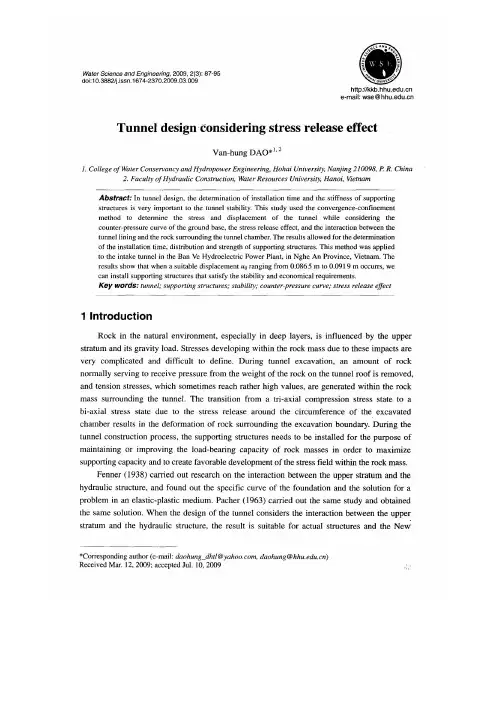
隧道设计考虑应力释放的影响摘要:在隧道设计中,支护时间的确定和刚性的支护体系对于维持隧道稳定是非常重要的,该研究所采用的收敛—约束法来确定的隧道的应力和位移,同时考虑到了地基承载力反压力曲线的位移、应力释放的影响以及隧道衬砌和岩石隧道周边洞室的相互作用,这个结论可以确定支护的时间和支护结构的强度和刚度。
这种方法曾适用于in the Ban Ve Hydroelectric Power Plant.in Nghe An Province.Vietnam 引水隧道。
结果表明,当位移u0在0.0865米到0.0919米之间时取一个合适的位移值,我们就可以通过架设支护结构来满足隧道的稳定性和经济的要求。
关键词:隧道支撑结构稳定性反压力曲线应力释放的影响1、引言岩石在自然环境中,特别是在深部地层当中,常常受到上部地层和重力的影响,由于这些因素的影响在岩体当中二次应力的发展是非常复杂,难以界定的。
隧道开挖过程中,一部分的岩石通常会受到来自隧道洞顶岩石的去除而产生的力—拉应力,有时拉应力会相当高,都会在隧道围岩的周边产生,由于岩石开挖洞周应力的释放会导致周边围岩的变形,从三向应力状态转变为双向应力状态。
在隧道施工过程中,架设支护结构的目的是为了提高和维持岩体的自承能力,以最大程度的发挥岩体的承载能力,并且在岩体内产生有利于发展的内应力场。
1938年,芬纳进行了上部地层和水力结构相互作用方面的研究,并发现了基础的特殊变化曲线和弹塑性介质的解决方案。
1963年,Pacher进行了同样的研究,并取得了同样的结果。
当隧道设计考虑上部地层和水工结构之间的相互作用时,其结果采用新奥法(NATM)施工和实际结构是比较适合的。
此外,在隧道设计中,隧道衬砌和洞室周围地层之间的相互作用,以及相应的地基反压力曲线,通常被考虑在内(Panet和Guenot1982; Panet1995年)。
在隧道设计中收敛—约束法通常被认为是有效的。
土木工程混凝土论文中英文资料外文翻译文献外文资料STUDIES ON IMPACT STRENGTH OF CONCRETESUBJECTED TO SUSTAINEDELEVATED TEMPERATUREConcrete has a remarkable fire resisting properties. Damage in concrete due to fire depends on a great extent on the intensity and duration of fire. Spalling cracking during heating are common concrete behaviour observed in the investigation of the fire affected structures. Plenty of literature is available on the studies of concrete based on time temperature cures. In power, oil sectorsand nuclear reactors concrete is exposed to high temperature for considerable period of time. These effects can be reckoned as exposure to sustained elevated temperature. The sustained elevated temperature may be varying from a few hours to a number of years depending upon practical condition of exposures. The knowledge on properties under such conditions is also of prime importance apart from the structures subjected to high intensity fire. Impact studies of structure subjected to sustained elevated temperature becomes more important as it involves sensitive structures which is more prone to attacks and accidents. In this paper impact studies on concrete subjected to sustained elevated temperature has been discussed. Experiments have been conducted on 180 specimens along with 180 companion cube specimens. The temperatures of 100°C, 200°C and 300°C for a duration of exposure of 2 hours 4 hours and 6 hours has been considered in the experiments. The results are logically analyzed and concluded.1. INTRODUCTIONThe remarkable property of concrete to resist the fire reduces the damage in a concrete structure whenever there is an accidental fire. In most of the cases the concrete remains intact with minor damages only. The reason being low thermal conductivity of concrete at higher temperatures and hence limiting the depth of penetration of firedamage. But when the concrete is subjected to high temperature for long duration the deterioration of concrete takes place. Hence it is essential to understand the strength and deformation characteristics of concrete subjected to temperature for long duration. In this paper an attempt has been made to study the variation in Impact Strength of concrete when subjected to a temperature range 100oC, 200oC and 300oC sustained for a period of 2 hrs, 4 hrs and 6 hrs.The review of the literature shows that a lot of research work [1 – 3] has taken place on the effect of elevated temperature on concrete. All these studies are based on time –temperature curves. Hence an attempt has been made to study the effect of sustained elevated temperature on impact strength of concrete and the results are compared with the compressive strength. The experimental programme has been planned for unstressed residual strength test based on the available facilities. Residual strength is the strength of heated and subsequently cooled concrete specimens expressed as percentage of the strength of unheated specimens.2. EXPERIMENTAL INVESTIGATION2.1. TEST SPECIMEN AND MATERIALSA total of 180 specimens were tested in the present study along with 180 companion cubes. An electric oven capable of reaching a maximum temperature of 300oC has been used for investigation. Fine and coarse aggregates conforming to IS383 has been used to prepare the specimen with mix proportions M1 = 1:2.1:3.95 w/c = 0.58, M2 = 1:1.15:3.56 w/c = 0.53, M3 = 1:0.8:2.4 w/c = 0.4.2.2 TEST VARIABLESThe effects of the following variables were studied.2.2.1 Size sSize of Impact Strength Test Specimen was 150 mm dial and 64 mm thickness and size of companion cube 150 x 150 x 150 mm.2.2.2 Maximum TemperatureIn addition to room temperature, the effect of three different temperatures (100oC, 200oC and 300oC) on the compressive strength was investigated.2.2.3 Exposure Time at Maximum TemperatureThree different exposure times were used to investigate the influence of heat on compressive strength; they are 2 hrs, 4 hrs and 6 hrs.2.2.4 Cooling MethodSpecimens were cooled in air to room temperature.3. TEST PROCEDUREAll the specimens were cast in steel moulds as per IS516 and each layer was compacted. Specimens were then kept in their moulds for 24 hours after which they were decoupled and placed into a curing tank until 28 days. After which the specimens were removed and were allowed to dry in room temperature. These specimens were kept in the oven and the required target temperature was set. Depending on the number of specimen kept inside the oven the time taken to reach the steady state was found to vary. After the steady state was reached the specimens were subjected to predetermined steady duration at the end of which the specimens are cooled to room temperature and tested.ACI drop weight impact strength test was adopted. This is the simplest method for evaluating impact resistance of concrete. The size of the specimen is 150 mm dial and 64 mm thickness. The disc specimens were prepared using steel moulds cured and heated and cooled as. This consists of a standard manually operated 4.54 kg hammer with 457 mm drop. A 64 mm hardened steel ball and a flat base plate with positioning bracket and lugs. The specimen is placed between the four guides pieces (lugs) located 4.8 mm away from the sample. A frame (positioning bracket) is then built in order to target the steel ball at the centre of concrete disc. The disc is coated at the bottom with a thin layer of petroleum jelly or heavy grease to reduce the friction between the specimen and base plate. The bottom part of the hammer unit was placed with its base upon the steel ball and the load was applied by dropping weight repeatedly. The loading was continued until the disc failed and opened up such that it touched three of the four positioning lugs. The number of blows that caused this condition is recorded as the failure strength. The companion cubes were tested for cube compression strength (fake).4. ANALYSIS AND RESULTS4.1 RESIDUAL COMPRESSIVE STRENGTH VS. TEMPERATUREFrom Table 1, at 100°C sustained elevated temperature it is seen that the residual strength of air cooled specimens of mixes M1, M2 and M3 has increased in strength 114% for M1 mix, 109% for M2 mix and 111% for M3 mix for 6 hours duration of exposure. When the sustained elevated temperature is to 200°C for air cooled specimens there is a decrease in strength up to 910% approximately for M1 mix for a duration of 6 hours, but in case of M2 mix it is 82% and for M3 mix it is 63% maximum for 6 hours duration of exposure. When the concrete mixes M1, M2 and M3 are exposed to 300°C sustained temperature there is a reduction in strength up to 78% for M1 mix for 6 hour duration of exposure.4.2 RESIDUAL COMPRESSIVE STRENGTH VS DURATION OF EXPOSUREFrom Table 1, result shows that heating up to 100°C for 2 hours and 4 hours, the residual strength of mix M1 has decreased where as the residual strength of mix M2 and M3 has increased. The residual strength is further increased for 6 hours duration of exposure in all the three mixes M1, M2 and M3 even beyond the strength at room temperature. When the specimens of mixes M1, M2 and M3 are exposed to 200°C for 2,4 and 6 hours of duration, it is observed that the residual strength has decreased below the room temperature and has reached 92% for M1 mix, 82 and 73% for M2 and M3 mix respectively. Concrete cubes of mixes M1, M2 and M3 when subjected to 300°C temperature for 2,4 and 6 hours the residual strength for mix M1 reduces to 92% for 2 hours up to 78% for six hours duration of exposure, for M2 mix 90% for 2 hours duration of exposure up to 76% for six hour duration of exposure, for M3 mix 88% up to 68% between 2 and 6 hours of duration of exposure.5. IMPACT STRENGTH OF CONCRETE5.1 RESIDUAL IMPACT STRENGTH VS TEMPERATUREFrom the table 1, it can be observed that for the sustained elevated temperature of 100°C the residual impact strength of all the specimens reduces and vary between 20 and 50% for mix M1, 15 to 40% for mix M2 and M3. When the sustained elevated temperature is 200°C the residual impact strength of all the mixes further decreases. The reduction is around 60-70% for mix M1, 55 to 65% for M2 and M3 mix. When the sustained elevated temperature is 300°C it is observed that the residual impact strength reduces further and vary between 85 and 70% for mix M1 and 85 to 90% for mix M2 and mix M3.5.2 RESIDUAL IMPACT STRENGTH VS DURATION OF EXPOSUREFrom the Table 1 and Figures 1 to 3, it can be observed that there is a reduction in impact strength when the sustained elevated temperature is 100°C for 2 hrs, 4 hrs and 6 hrs, and its range is 15 to 50% for all the mixes M1, M2 and M3. The influence of duration of exposure is higher for mix M1 which decreases more rapidly as compared to mix M2 and mix M3 for the same duration of exposure. When the specimens are subjected to sustained elevated temperature of 200°C for 2,4 and 6 hour of duration, further reduction in residual impact strength is observed as compared to at 100°C. The reduction is in the range of 55-70% for all the mixes. The six hour duration of exposure has a greater influence on the residual impact strength of concrete. When the sustained elevated temperature is 300°C for 2,4 and 6 hours duration of exposure the residualimpact strength reduces. It can be seen that both temperature and duration of exposure have a very high influence on the residual impact strength of concrete which shows a reduction up to 90% approximately for all the mixes.6. CONCLUSIONThe compressive strength of concrete increases at 100oC when exposed to sustained elevated temperature. The compressive strength of concrete decreases when exposed to 200°C and 300°C from 10 to 30% for 6 hours of exposure. Residual impact strength reduces irrespective of temperature and duration. Residual impact strength decreases at a higher rate of 20% to 85% as compared to compressive strength between 15% and 30 % when subjected to sustained elevated temperature. The impact strength reduces at a higher rate as compared to compressive strength when subjected to sustained elevated temperature.混凝土受持续高温影响的强度的研究混凝土具有显着的耐火性能。
土木工程专业毕业设计外文文献翻译2篇XXXXXXXXX学院学士学位毕业设计(论文)英语翻译课题名称英语翻译学号学生专业、年级所在院系指导教师选题时间Fundamental Assumptions for Reinforced ConcreteBehaviorThe chief task of the structural engineer is the design of structures. Design is the determination of the general shape and all specific dimensions of a particular structure so that it will perform the function for which it is created and will safely withstand the influences that will act on it throughout useful life. These influences are primarily the loads and other forces to which it will be subjected, as well as other detrimental agents, such as temperature fluctuations, foundation settlements, and corrosive influences, Structural mechanics is one of the main tools in this process of design. As here understood, it is the body of scientific knowledge that permits one to predict with a good degree of certainly how a structure of give shape and dimensions will behave when acted upon by known forces or other mechanical influences. The chief items of behavior that are of practical interest are (1) the strength of the structure, i. e. , that magnitude of loads of a give distribution which will cause the structure to fail, and (2) the deformations, such as deflections and extent of cracking, that the structure will undergo when loaded underservice condition.The fundamental propositions on which the mechanics of reinforced concrete is based are as follows:1.The internal forces, such as bending moments, shear forces, and normal andshear stresses, at any section of a member are in equilibrium with the effect of the external loads at that section. This proposition is not an assumption but a fact, because any body or any portion thereof can be at rest only if all forces acting on it are in equilibrium.2.The strain in an embedded reinforcing bar is the same as that of thesurrounding concrete. Expressed differently, it is assumed that perfect bonding exists between concrete and steel at the interface, so that no slip can occur between the two materials. Hence, as the one deforms, so must the other. With modern deformed bars, a high degree of mechanical interlocking is provided in addition to the natural surface adhesion, so this assumption is very close to correct.3.Cross sections that were plane prior to loading continue to be plan in themember under load. Accurate measurements have shown that when a reinforced concrete member is loaded close to failure, this assumption is not absolutely accurate. However, the deviations are usually minor.4.In view of the fact the tensile strength of concrete is only a small fraction ofits compressive strength; the concrete in that part of a member which is in tension is usually cracked. While these cracks, in well-designed members, are generally so sorrow as to behardly visible, they evidently render the cracked concrete incapable of resisting tension stress whatever. This assumption is evidently a simplification of the actual situation because, in fact, concrete prior to cracking, as well as the concrete located between cracks, does resist tension stresses of small magnitude. Later in discussions of the resistance of reinforced concrete beams to shear, it will become apparent that under certain conditions this particular assumption is dispensed with and advantage is taken of the modest tensile strength that concrete can develop.5.The theory is based on the actual stress-strain relation ships and strengthproperties of the two constituent materials or some reasonable equivalent simplifications thereof. The fact that novelistic behavior is reflected in modern theory, that concrete is assumed to be ineffective in tension, and that the joint action of the two materials is taken into consideration results in analytical methods which are considerably more complex and also more challenging, than those that are adequate for members made of a single, substantially elastic material.These five assumptions permit one to predict by calculation the performance of reinforced concrete members only for some simple situations. Actually, the joint action of two materials as dissimilar and complicated as concrete and steel is so complex that it has not yet lent itself to purely analytical treatment. For this reason, methods of design and analysis, while using these assumptions, are very largely based on the results of extensive and continuing experimental research. They are modified and improved as additional test evidence becomes available.钢筋混凝土的基本假设作为结构工程师的主要任务是结构设计。
Civil engineering introduction papers[英语原文]Abstract: the civil engineering is a huge discipline, but the main one is building, building whether in China or abroad, has a long history, long-term development process. The world is changing every day, but the building also along with the progress of science and development. Mechanics findings, material of update, ever more scientific technology into the building. But before a room with a tile to cover the top of the house, now for comfort, different ideas, different scientific, promoted the development of civil engineering, making it more perfect.[key words] : civil engineering; Architecture; Mechanics, Materials.Civil engineering is build various projects collectively. It was meant to be and "military project" corresponding. In English the history of Civil Engineering, mechanical Engineering, electrical Engineering, chemical Engineering belong to to Engineering, because they all have MinYongXing. Later, as the project development of science and technology, mechanical, electrical, chemical has gradually formed independent scientific, to Engineering became Civil Engineering of specialized nouns. So far, in English, to Engineering include water conservancy project, port Engineering, While in our country, water conservancy projects and port projects also become very close and civil engineering relatively independent branch. Civil engineering construction of object, both refers to that built on the ground, underground water engineering facilities, also refers to applied materials equipment and conduct of the investigation, design and construction, maintenance, repair and other professional technology.Civil engineering is a kind of with people's food, clothing, shelter and transportation has close relation of the project. Among them with "live" relationship is directly. Because, to solve the "live" problem must build various types of buildings. To solve the "line, food and clothes" problem both direct side, but also a indirect side. "Line", must build railways, roads, Bridges, "Feed", must be well drilling water, water conservancy, farm irrigation, drainage water supply for the city, that is direct relation. Indirectly relationship is no matter what you do, manufacturing cars, ships, or spinning and weaving, clothing, or even production steel, launch satellites, conducting scientific research activities are inseparable from build various buildings, structures and build all kinds of project facilities.Civil engineering with the progress of human society and development, yet has evolved into large-scale comprehensive discipline, it has out many branch, such as: architectural engineering, the railway engineering, road engineering, bridge engineering, special engineering structure, waterand wastewater engineering, port engineering, hydraulic engineering, environment engineering disciplines. [1]Civil engineering as an important basic disciplines, and has its important attributes of: integrated, sociality, practicality, unity. Civil engineering for the development of national economy and the improvement of people's life provides an important material and technical basis, for many industrial invigoration played a role in promoting, engineering construction is the formation of a fixed asset basic production process, therefore, construction and real estate become in many countries and regions, economic powerhouses.Construction project is housing planning, survey, design, construction of the floorboard. Purpose is for human life and production provide places.Houses will be like a man, it's like a man's life planning environment is responsible by the planners, Its layout and artistic processing, corresponding to the body shape looks and temperament, is responsible by the architect, Its structure is like a person's bones and life expectancy, the structural engineer is responsible, Its water, heating ventilation and electrical facilities such as the human organ and the nerve, is by the equipment engineer is responsible for. Also like nature intact shaped like people, in the city I district planning based on build houses, and is the construction unit, reconnaissance unit, design unit of various design engineers and construction units comprehensive coordination and cooperation process.After all, but is structural stress body reaction force and the internal stress and how external force balance. Building to tackle, also must solve the problem is mechanical problems. We have to solve the problem of discipline called architectural mechanics. Architectural mechanics have can be divided into: statics, material mechanics and structural mechanics three mechanical system. Architectural mechanics is discussion and research building structure and component in load and other factors affecting the working condition of, also is the building of intensity, stiffness and stability. In load, bear load and load of structure and component can cause the surrounding objects in their function, and the object itself by the load effect and deformation, and there is the possibility of damage, but the structure itself has certain resistance to deformation and destruction of competence, and the bearing capacity of the structure size is and component of materials, cross section, and the structural properties of geometry size, working conditions and structure circumstance relevant. While these relationships can be improved by mechanics formula solved through calculation.Building materials in building and has a pivotal role. Building material is with human society productivity and science and technologyimproves gradually developed. In ancient times, the human lives, the line USES is the rocks andTrees. The 4th century BC, 12 ~ has created a tile and brick, humans are only useful synthetic materials made of housing. The 17th century had cast iron and ShouTie later, until the eighteenth century had Portland cement, just make later reinforced concrete engineering get vigorous development. Now all sorts of high-strength structural materials, new decoration materials and waterproof material development, criterion and 20th century since mid organic polymer materials in civil engineering are closely related to the widely application. In all materials, the most main and most popular is steel, concrete, lumber, masonry. In recent years, by using two kinds of material advantage, will make them together, the combination of structure was developed. Now, architecture, engineering quality fit and unfit quality usually adopted materials quality, performance and using reasonable or not have direct connection, in meet the same technical indicators and quality requirements, under the precondition of choice of different material is different, use method of engineering cost has direct impact.In construction process, building construction is and architectural mechanics, building materials also important links. Construction is to the mind of the designer, intention and idea into realistic process, from the ancient hole JuChao place to now skyscrapers, from rural to urban country road elevated road all need through "construction" means. A construction project, including many jobs such as dredging engineering, deep foundation pit bracing engineering, foundation engineering, reinforced concrete structure engineering, structural lifting project, waterproofing, decorate projects, each type of project has its own rules, all need according to different construction object and construction environment conditions using relevant construction technology, in work-site.whenever while, need and the relevant hydropower and other equipment composition of a whole, each project between reasonable organizing and coordination, better play investment benefit. Civil engineering construction in the benefit, while also issued by the state in strict accordance with the relevant construction technology standard, thus further enhance China's construction level to ensure construction quality, reduce the cost for the project.Any building built on the surface of the earth all strata, building weight eventually to stratum, have to bear. Formation Support building the rocks were referred to as foundation, and the buildings on the ground and under the upper structure of self-respect and liable to load transfer to the foundation of components or component called foundation. Foundation, and the foundation and the superstructure is a building of three inseparable part. According to the function is different, but in load, under the action of them are related to each other, is theinteraction of the whole. Foundation can be divided into natural foundation and artificial foundation, basic according to the buried depth is divided into deep foundation and shallow foundation. , foundation and foundation is the guarantee of the quality of the buildings and normal use close button, where buildings foundation in building under loads of both must maintain overall stability and if the settlement of foundation produce in building scope permitted inside, and foundation itself should have sufficient strength, stiffness and durability, also consider repair methods and the necessary foundation soil retaining retaining water and relevant measures. [3]As people living standard rise ceaselessly, the people to their place of building space has become not only from the number, and put forward higher requirement from quality are put car higher demands that the environment is beautiful, have certain comfort. This needs to decorate a building to be necessary. If architecture major engineering constitutes the skeleton of the building, then after adornment building has become the flesh-and-blood organism, final with rich, perfect appearance in people's in front, the best architecture should fully embody all sorts of adornment material related properties, with existing construction technology, the most effective gimmick, to achieve conception must express effect. Building outfit fix to consider the architectural space use requirement, protect the subject institutions from damage, give a person with beautifulenjoying, satisfy the requirements of fire evacuation, decorative materials and scheme of rationality, construction technology and economic feasibility, etc. Housing construction development and at the same time, like housing construction as affecting people life of roads, Bridges, tunnels has made great progress.In general civil engineering is one of the oldest subjects, it has made great achievements, the future of the civil engineering will occupy in people's life more important position. The environment worsening population increase, people to fight for survival, to strive for a more comfortable living environment, and will pay more attention to civil engineering. In the near future, some major projects extimated to build, insert roller skyscrapers, across the oceanBridges, more convenient traffic would not dream. The development of science and technology, and the earth is deteriorating environment will be prompted civil engineering to aerospace and Marine development, provide mankind broader space of living. In recent years, engineering materials mainly is reinforced concrete, lumber and brick materials, in the future, the traditional materials will be improved, more suitable for some new building materials market, especially the chemistry materials will promote the construction of towards a higher point. Meanwhile, design method of precision, design work of automation, information and intelligent technology of introducing, will be people have a morecomfortable living environment. The word, and the development of the theory and new materials, the emergence of the application of computer, high-tech introduction to wait to will make civil engineering have a new leap.This is a door needs calm and a great deal of patience and attentive professional. Because hundreds of thousands, even hundreds of thousands of lines to building each place structure clearly reflected. Without a gentle state of mind, do what thing just floating on the surface, to any a building structure, to be engaged in business and could not have had a clear, accurate and profound understanding of, the nature is no good. In this business, probably not burn the midnight oil of courage, not to reach the goal of spirit not to give up, will only be companies eliminated.This is a responsible and caring industry. Should have a single responsible heart - I one's life in my hand, thousands of life in my hand. Since the civil, should choose dependably shoulder the responsibility.Finally, this is a constant pursuit of perfect industry. Pyramid, spectacular now: The Great Wall, the majestic... But if no generations of the pursuit of today, we may also use the sort of the oldest way to build this same architecture. Design a building structure is numerous, but this is all experienced centuries of clarification, through continuous accumulation, keep improving, innovation obtained. And such pursuit, not confined in the past. Just think, if the design of a building can be like calculation one plus one equals two as simple and easy to grasp, that was not for what? Therefore, a civil engineer is in constant of in formation. One of the most simple structure, the least cost, the biggest function. Choose civil, choosing a steadfast diligence, innovation, pursuit of perfect path.Reference:[1] LuoFuWu editor. Civil engineering (professional). Introduction to wuhan. Wuhan university of technology press. 2007[2] WangFuChuan, palace rice expensive editor. Construction engineering materials. Beijing. Science and technology literature press. 2002[3] jiang see whales, zhiming editor. Civil engineering introduction of higher education press. Beijing.. 1992土木工程概论 [译文]摘要:土木工程是个庞大的学科,但最主要的是建筑,建筑无论是在中国还是在国外,都有着悠久的历史,长期的发展历程。

土木工程专业建筑施工外文翻译文献原文:Building construction concrete crack ofprevention and processingAbstractThe crack problem of concrete is a widespread existence but again difficult in solve of engineering actual problem, this text carried on a study analysis to a little bit familiar crack problem in the concrete engineering, and aim at concrete the circumstance put forward some prevention, processing measure.Keyword:Concrete crack prevention processingForewordConcrete's ising 1 kind is anticipate by the freestone bone, cement, water and other mixture but formation of the in addition material of quality brittleness not and all material.Because the concrete construction transform with oneself, control etc. a series problem, harden model of in the concrete existence numerous tiny hole, spirit cave and tiny crack, is exactly because these beginning start blemish of existence just make the concrete present one some not and all the characteristic of quality.The tiny crack is a kind of harmless crack and accept concrete heavy, defend Shen and a little bit other use function not a creation to endanger.But after the concrete be subjected to lotus carry, difference in temperature etc. function, tiny crack would continuously of expand with connect, end formation we can see without the aid of instruments of macro view the crack be also the crack that the concrete often say in the engineering.Concrete building and Gou piece usually all take sewer to make of, because of crack of existence and development usually make inner part of reinforcing bar etc. material creation decay, lower reinforced concrete material of loading ability, durable and anti- Shen ability, influence building of external appearance, service life, severity will threat arrive people's life and property safety.A lot of all of crash of engineerings is because of the unsteady development of the crack with the result that.Modern age science research with a great deal of of the concrete engineeringpractice certificate, in the concrete engineering crack problem is ineluctable, also acceptable in certainly of the scope just need to adopt valid of measure will it endanger degree control at certain of scope inside.The reinforced concrete norm is also explicit provision:Some structure at place of dissimilarity under the condition allow existence certain the crack of width.But at under construction should as far as possible adopt a valid measure control crack creation, make the structure don't appear crack possibly or as far as possible decrease crack of amount and width, particularly want to as far as possible avoid harmful crack of emergence, insure engineering quality thus.Concrete crack creation of the reason be a lot of and have already transformed to cause of crack:Such as temperature variety, constringency, inflation, the asymmetry sink to sink etc. reason cause of crack;Have outside carry the crack that the function cause;Protected environment not appropriate the crack etc. caused with chemical effect.Want differentiation to treat in the actual engineering, work°out a problem according to the actual circumstance.In the concrete engineering the familiar crack and the prevention1.Stem Suo crack and preventionStem the Suo crack much appear after the concrete protect be over of a period of time or concrete sprinkle to build to complete behind of around a week.In the cement syrup humidity of evaporate would creation stem Suo, and this kind of constringency is can't negative.Stem Suo crack of the creation be main is because of concrete inside outside humidity evaporate degree dissimilarity but cause to transform dissimilarity of result:The concrete is subjected to exterior condition of influence, surface humidity loss lead quick, transform bigger, inner part degree of humidity variety smaller transform smaller, bigger surface stem the Suo transform to be subjected to concrete inner part control, creation more big pull should dint but creation crack.The relative humidity is more low, cement syrup body stem Suo more big, stem the Suo crack be more easy creation.Stem the Suo crack is much surface parallel lines form or the net shallow thin crack, width many between 0.05-0.2 mm, the flat surface part much see in the big physical volume concrete and follow it morein thinner beam plank short to distribute.Stem Suo crack usually the anti- Shen of influence concrete, cause the durable of the rust eclipse influence concrete of reinforcing bar, under the function of the water pressure dint would creation the water power split crack influence concrete of loading dint etc..Concrete stem the Suo be main with water ash of the concrete ratio, the dosage of the composition, cement of cement, gather to anticipate of the dosage of the property and dosage, in addition etc. relevant.Main prevention measure:While being to choose to use the constringency quantity smaller cement, general low hot water mire and powder ash from stove cement in the adoption, lower the dosage of cement.Two is a concrete of stem the Suo be subjected to water ash ratio of influence more big, water ash ratio more big, stem Suo more big, so in the concrete match the ratio the design should as far as possible control good water ash ratio of choose to use, the Chan add in the meantime accommodation of reduce water.Three is strict control concrete mix blend with under construction of match ratio, use of concrete water quantity absolute can't big in match ratio design give settle of use water quantity.Four is the earlier period which strengthen concrete to protect, and appropriate extension protect of concrete time.Winter construction want to be appropriate extension concrete heat preservation to overlay time, and Tu2 Shua protect to protect.Five is a constitution the accommodation is in the concrete structure of the constringency sew.2.The Su constringency crack and preventionSu constringency is the concrete is before condense, surface because of lose water quicker but creation of constringency.The Su constringency crack is general at dry heat or strong wind the weather appear, crack's much presenting in the center breadth, both ends be in the centerthin and the length be different, with each other not coherent appearance.Shorter crack general long 20-30 cm, the longer crack can reach to a 2-3 m, breadth 1-5 mm.It creation of main reason is:The concrete is eventually almost having no strength or strength before the Ning very small, perhaps concrete just eventually Ning but strength very hour, be subjected to heat or compare strong wind dint of influence, the concrete surface lose water to lead quick,result in in the capillary creation bigger negative press but make a concrete physical volume sharply constringency, but at this time the strength of concrete again can't resist its constringency, therefore creation cracked.The influence concrete Su constringency open the main factor of crack to have water ash ratio, concrete of condense time, environment temperature, wind velocity, relative humidity...etc..Main prevention measure:One is choose to use stem the Suo value smaller higher Huo sour salt of the earlier period strength or common the Huo sour brine mire.Two is strict the control water ash ratio, the Chan add to efficiently reduce water to increment the collapse of concrete fall a degree and with easy, decrease cement and water of dosage.Three is to sprinkle before building concrete, water basic level and template even to soak through.Four is in time to overlay the perhaps damp grass mat of the plastics thin film, hemp slice etc., keep concrete eventually before the Ning surface is moist, perhaps spray to protect etc. to carry on protect in the concrete surface.Five is in the heat and strong wind the weather to want to establish to hide sun and block breeze facilities, protect in time.3.Sink to sink crack and preventionThe creation which sink to sink crack is because of the structure foundation soil quality not and evenly, loose soft or return to fill soil dishonest or soak in water but result in the asymmetry sink to decline with the result that;Perhaps because of template just degree shortage, the template propped up to once be apart from big or prop up bottom loose move etc. to cause, especially at winter, the template prop up at jelly soil up, jelly the soil turn jelly empress creation asymmetry to sink to decline and cause concrete structure creation crack.This kind crack many is deep enter or pierce through sex crack, it alignment have something to do with sinking to sink a circumstance, general follow with ground perpendicular or present 30 °s-45 °Cape direction development, bigger sink to sink crack, usually have certain of wrong, crack width usually with sink to decline quantity direct proportion relation.Crack width under the influence of temperature variety smaller.The foundation after transform stability sink to sink crack also basic tend in stability.Main prevention measure:One is rightness loose soft soil, return to fill soilfoundation a construction at the upper part structure front should carry on necessity of Hang solid with reinforce.Two is the strength that assurance template is enough and just degree, and prop up firm, and make the foundation be subjected to dint even.Three is keep concrete from sprinkle infusing the foundation in the process is soak by water.Four is time that template tore down to can't be too early, and want to notice to dismantle a mold order of sequence.Five is at jelly soil top take to establish template to notice to adopt certain of prevention measure.4.Temperature crack and preventionTemperature crack much the occurrence is in big surface or difference in temperature variety of the physical volume concrete compare the earth area of the concrete structure.Concrete after sprinkling to build, in the hardening the process, cement water turn a creation a great deal of of water turn hot, .(be the cement dosage is in the 350-550 kg/m 3, each sign square the rice concrete will release a calories of 17500-27500 kJ and make concrete internal thus the temperature rise to reach to 70 ℃or so even higher)Because the physical volume of concrete be more big, a great deal of of water turn hot accumulate at the concrete inner part but not easy send forth, cause inner part the temperature hoick, but the concrete surface spread hot more quick, so formation inside outside of bigger difference in temperature, the bigger difference in temperature result in inner part and exterior hot the degree of the bulge cold Suo dissimilarity, make concrete surface creation certain of pull should dint.When pull should dint exceed the anti- of concrete pull strength extreme limit, concrete surface meeting creation crack, this kind of crack much occurrence after the concrete under construction period.In the concrete of under construction be difference in temperature variety more big, perhaps is a concrete to be subjected to assault of cold wave etc., will cause concrete surface the temperature sharply descend, but creation constringency, surface constringency of the concrete be subjected to inner part concrete of control, creation very big of pull should dint but creation crack, this kind of crack usually just in more shallow scope of the concrete surface creation.The alignment of the temperature crack usually none settle regulation, big areastructure the crack often maneuver interleave;The size bigger structure of the beam plank length, the crack run parallel with short side more;Thorough with pierce through sex of temperature crack general and short side direction parallelism or close parallelism, crack along long side cent the segment appear, in the center more airtight.Crack width the size be different, be subjected to temperature variety influence more obvious, winter compare breadth, summer more narrow.The concrete temperature crack that the heat inflation cause is usually in the center the thick both ends be thin, but cold Suo crack of thick thin variety not too obvious.The emergence of the this kind crack will cause the rust eclipse of reinforcing bar, the carbonization of concrete, the anti- jelly which lower concrete melt, anti- tired and anti- Shen ability etc..Main prevention measure:One is as far as possible choose to use low hot or medium hot water mire, like mineral residue cement, powder ash from stove cement...etc..Two is a decrease cement dosage, cement dosage as far as possible the control is in the 450 kg/m 3 following.Three is to lower water ash ratio, water ash of the general concrete ratio control below 0.6.Four is improvement the bone anticipate class to go together with, the Chan add powder ash from stove or efficiently reduce water etc. to come to reduce cement dosage and lower water to turn hot.Five is an improvement concrete of mix blend to process a craft, lower sprinkle of concrete to build temperature.Six is the in addition that the Chan add a have of fixed amount to reduce water and increase Su, slow Ning etc. function in the concrete, improvement the concrete mix to match a thing of mobility, protect water, lower water to turn hot, postpone hot Feng of emergence time.Seven is the heat season sprinkle to build can the adoption take to establish to hide sun plank etc. assistance measure control concrete of Wen Sheng, lower to sprinkle temperature of build the concrete.Eight is the temperature of big physical volume concrete should the dint relate to structure size, concrete structure size more big, temperature should dint more big, so want reasonable arrangement construction work preface, layering, cent the piece sprinkle to build, for the convenience of in spread hot, let up control.Nine is at great inner part constitution of the physical volume concrete cooloff piping, cold water perhaps cold air cool off, let up concrete of inside outside difference in temperature.Ten is the supervision which strengthen concrete temperature, adopt to cool off in time, protection measure.11 is to reserve temperature constringency to sew.12 is to let up to control, sprinkle proper before building concrete in the Ji rock and old concrete top build a 5 mm or so sand mat a layer or usage asphalt etc. material Tu2 Shua.13 is to strengthen concrete to protect, the concrete after sprinkle build use moist grass Lian in time, hemp slice's etc. overlay, and attention sprinkle water to protect, appropriate extension protect time, assurance the concrete surface be slow-moving cool off.At the cold season, concrete surface should constitution heat preservation measure, in order to prevent cold wave assault.14 is the allocation be a little amount in the concrete of reinforcing bar perhaps add fiber material concrete of temperature crack control at certain of scope inside.5.Crack and prevention that the chemical reaction causeAlkali bone's anticipating the crack that reaction crack and reinforcing bar rust eclipse cause is the most familiar in the reinforced concrete structure of because of chemical reaction but cause of crack.The concrete blend a future reunion creation some alkalescence ion, these ion with some activity the bone anticipate creation chemical reaction and absorb surroundings environment in of water but the physical volume enlarge, make concrete crisp loose, inflation open crack.In this kind of crack general emergence concrete structure usage period, once appear very difficult remediable, so should at under construction adopt valid the measure carry on prevention.Main of prevention measure:While being to choose to anticipate with the alkali activity small freestone bone.Two is the in addition which choose to use low lye mire with low alkali or have no alkali.Three is the Chan which choose to use accommodation with anticipate to repress an alkali bone to anticipate reaction.Because the concrete sprinkle to build, flap Dao bad perhaps is a reinforcing bar protection layer thinner, the harmful material get into concrete to make reinforcing bar creation rust eclipse, the reinforcing bar physical volume of the rusteclipse inflation, cause concrete bulge crack, the crack of this kind type much is a crack lengthways, follow the position of reinforcing bar ually of prevent measure from have:One is assurance reinforcing bar protection the thickness of the layer.Two is a concrete class to go together with to want good.Three is a concrete to sprinkle to note and flap Dao airtight solid.Four is a reinforcing bar surface layer Tu2 Shua antisepsis coating.Crack processingThe emergence of the crack not only would influence structure of whole with just degree, return will cause the rust eclipse of reinforcing bar, acceleration concrete of carbonization, lower durable and anti- of concrete tired, anti- Shen ability.Therefore according to the property of crack and concrete circumstance we want differentiation to treat, in time processing, with assurance building of safety usage.The repair measure of the concrete crack is main to have the following some method:Surface repair method, infuse syrup, the Qian sew method, the structure reinforce a method, concrete displacement method, electricity chemistry protection method and imitate to living from heal method.Surface repair the method be a kind of simple, familiar of repair method, it main be applicable to stability and to structure loading the ability don't have the surface crack of influence and deep enter crack of processing.The processing measure that is usually is a surface in crack daubery cement syrup, the wreath oxygen gum mire or at concrete surface Tu2 Shua paint, asphalt etc. antisepsis material, at protection of in the meantime for keeping concrete from continue under the influence of various function to open crack, usually can adoption the surface in crack glue to stick glass fiber cloth etc. measure.1, infuse syrup, the Qian sew methodInfuse a syrup method main the concrete crack been applicable to have influence or have already defend Shen request to the structure whole of repair, it is make use of pressure equipments gum knot the material press into the crack of concrete, gum knot the material harden behind and concrete formation one bewhole, thus reinforce of purpose.The in common use gum knot material has the cement the syrup, epoxy, A Ji C Xi sour ester and gather ammonia ester to equalize to learn material.The Qian sew a method is that the crack be a kind of most in common use method in, it usually is follow the crack dig slot, the Qian fill Su in the slot or rigid water material with attain closing crack of purpose.The in common use Su material has PVC gum mire, plastics ointment, the D Ji rubber etc.;In common use rigid water material is the polymer cement sand syrup.2, the structure reinforce a methodWhen the crack influence arrive concrete structure of function, will consideration adopt to reinforce a method to carry on processing to the concrete structure.The structure reinforce medium in common use main have the following a few method:The piece of enlargement concrete structure in every aspect accumulate, outside the Cape department of the Gou piece pack type steel, adoption prepare should the dint method reinforce, glue to stick steel plate to reinforce, increase to establish fulcrum to reinforce and jet the concrete compensation reinforce.3, concrete displacement methodConcrete displacement method is processing severity damage concrete of a kind of valid method, this method be first will damage of the concrete pick and get rid of, then again displacement go into new of concrete or other material.The in common use displacement material have:Common concrete or the cement sand syrup, polymer or change sex polymer concrete or sand syrup.4, the electricity chemistry protection methodThe electricity chemistry antisepsis is to make use of infliction electric field in lie the quality of electricity chemical effect, change concrete or reinforced concrete the environment appearance of the place, the bluntness turn reinforcing bar to attain the purpose of antisepsis.Cathode protection method, chlorine salt's withdrawing a method, alkalescence to recover a method is a chemistry protection method in three kinds of in common use but valid method.The advantage of this kind of method is aprotection method under the influence of environment factor smaller, apply reinforcing bar, concrete of long-term antisepsis, since can used for crack structure already can also used for new set up structure.5, imitate to living from legal moreImitate to living from heal the method be a kind of new crack treatment, its mimicry living creature organization secrete a certain material towards suffering wound part auto, but make the wound part heal of function, join some and special composition(such as contain to glue knot of the liquid Xin fiber or capsule) in the concrete of the tradition the composition, at concrete inner part formation the intelligence type imitate to living from heal nerve network system, be the concrete appear crack secrete a parts of liquid Xin fiber can make the crack re- heal.ConclusionThe crack is widespread in the concrete structure existence of a kind of phenomenon, it of emergence not only will lower the anti- Shen of building ability, influence building of usage function, and will cause the rust eclipse of reinforcing bar, the carbonization of concrete, lower the durable of material, influence building of loading ability, so want to carry on to the concrete crack earnest research, differentiation treat, adoption reasonable of the method carry on processing, and at under construction adopt various valid of prevention measure to prevention crack of emergence and development, assurance building and Gou piece safety, stability work.中文:建筑施工混凝土裂缝的预防与处理混凝土的裂缝问题是一个普遍存在而又难于解决的工程实际问题,本文对混凝土工程中常见的一些裂缝问题进行了探讨分析,并针对具体情况提出了一些预防、处理措施。
Experimental research on seismic behavior of abnormal jointin reinforced concrete frameAbstract :Based on nine plane abnormal joint s , one space abnormal joint experiment and a p seudo dynamic test of a powerplant model , the work mechanism and the hysteretic characteristic of abnormal joint are put to analysis in this paper. A conception of minor core determined by the small beam and small column , and a conclusion that the shear capacity of ab2normal joint depends on minor core are put forward in this paper. This paper also analyzes the effect s of axial compres2 sion , horizontal stirrup s and section variation of beam and column on the shear behavior of abnormal joint . Finally , the formula of shear capacity for abnormal joint in reinforced concrete f rame is provided.Key words : abnormal j oint ; minor core ; seismic behavior ; shear ca paci t yCLC number :TU375. 4 ; TU317. 1 Document code :A Article ID :100627930 (2006) 022*******1 Int roductionFor reinforced concrete f rame st ructure , t he joint is a key component . It is subjected to axialcomp ression , bending moment and shear force. The key is whet her the joint has enough shear capaci2ty. The Chinese Code f or S eismic Desi gn of B ui l di ngs ( GB5001122001) adopt s the following formulato calculate t he shear capacity of the reinforced concrete f rame joint .V j = 1. 1ηj f t b j h j + 0. 05ηj Nb jb c+ f yv A svjh b0 - a′ss(1)Where V j = design value of t he seismic shear capacity of the joint core section ;ηj = influential coefficient of t he orthogonal beam to the column ;f t = design value of concrete tensile st rength ;b j = effective widt h of the joint core section ;h j = dept h of the joint core section , Which can be adopted as t he depth of the column section int he verification direction ;N = design value of axial compression at t he bot tom of upper column wit h considering the combi2 nation of the eart hquake action , When N > 015 f c b c h c , let N = 0. 5 f c b c h c ;b c = widt h of t he column section ;f yv = design value of t he stirrup tensile st rengt h ;A svj = total stirrup area in a set making up one layer ;h b0 = effective dept h of t he beam.If t he dept h of two beams at the side of t he joint is unequal , h b0 = t he average depth of two beams.a′s = distance f rom the cent roid of the compression beam steel bar to the ext reme concrete fiber . s = distance of t he stirrup .Eq. 1 is based on t he formula in t he previous seismiccode[1 ] and some modifications made eavlicr and it is suit2able to the normal joint of reinforced concrete f rame , butnot to t he abnormal one which has large different in t hesection of t he upper column and lower one (3 600 mm and1 200 mm) , lef t beam and right beam (1 800 mm and 1200 mm) . The shear capacity of abnormal joint s calculat2ed by Eq. 1 may cause some unsafe result s. A type of ab2normal joint which of ten exist s in t he power plant st ruc2t ure is discussed ( see Fig. 1) , and it s behavior was st ud2ied based on t he experiment in t his paper2 Experimental workAccording to the above problem , and t he experiment of plane abnormal joint s and space abnormal joint , a p seudo dynamic test of space model of power plant st ruct ure was carried out . The aim of t hisst udy is to set up a shear force formula and to discuss seismic behavior s of t he joint s.According to the characteristic of t he power plant st ruct ure , nine abnormal joint s and one space abnormal joint were designed in t he experiment . The scale of the model s is one2fif t h. Tab. 1 and Tab.2 show t he dimensions and reinforcement detail s of t he specimens.Fig. 2 shows the typical const ruction drawing of t he specimen. Fig. 3 shows the loading set up . These specimens are subjected to low2cyclic loading , the loading process of which is cont rolled by force and displacement , t he preceding yield loading by force and subsequent yield by t he displacement .The shear deformation of the joint core , t he st rain of the longit udinal steel and t he stirrup are main measuring items.3 Analysis of test result s3. 1 Main resultsTab. 3 shows t he main result s of t he experiment .3. 2 Failure process of specimenBased on t he experiment , t he process of t he specimens’failure includes four stages , namely , t he initial cracking , t he t horough cracking , the ultimate stage and t he failure stage.(1) Initial cracking stageWhen t he first diagonal crack appears along t he diagonal direction in t he core af ter loading , it s widt h is about 0. 1mm , which is named initial cracking stage of joint core. Before t he initial cracking stage , t he joint remains elastic performance , and the variety of stiff ness is not very obvious on t hep2Δcurve. At t his stage concrete bear s most of the core shear force while stirrup bears few. At t he timewhen t he initial crack occur s , t he st ress of t he stirrup at t he crack increase sharply and t he st rain is a2bout 200 ×10 - 6 —300 ×10 - 6 . The shear deformation of t he core at t his stage is very small (less than 1×10 - 3 radian ,generally between 0. 4 ×10 - 3 and 0. 8 ×10 - 3 radian) .(2) Thorough cracking stageWit h the load increasing following t he initial cracking stage , the second and t hird crossing diago2 nal cracks will appear at t he core. The core is cut into some small rhombus pieces which will become at least one main inclined crack across t he core diagonal . The widt h of cracks enlarges obviously , andt he wider ones are generally about 0. 5mm , which is named core t horough cracking stage. The st ress of stirrup increases obviously , and the stirrup in t he middle of t he core is near to yielding or has yiel2 ded. The joint core shows nonlinear property on t he p2Δcurve , and it enter s elastic2plastic stage. Theload at t horough cracking stage is about 80 % —90 % load.(3) Ultimate stageAt t his stage , t he widt h of t he cracks is about 1mm or more and some new cracks continue to oc2 cur . The shear deformation at t he core is much larger and concrete begins to collap se. Af ter several cyclic loading , the force reaches the maximum value , which is called ultimate stage. The load increase is due to t he enhancing of the concrete aggregate mechanical f riction between cracks. At t he same timet he st ress of stirrup increases gradually. On t he one hand stirrup resist s t he horizontal shear , and on t he ot her hand the confinement effect to t he expanding compression concrete st rengthens continuous2ly , which can also improve t he shear capacity of diagonal compression bar mechanism.(4) Failure stageAs the load circulated , concrete in t he core began to collap se , and t he deformation increased sharply , while the capacity began to drop . It was found t hat t he slip of reinforcement in t he beam wasvery serious in t he experiment . Wit h t he load and it s circulation time increasing , t he zoon wit houtbond gradually permeated towards t he internal core , enhancing t he burden of t he diagonal compressionbar mechanism and accelerates the compression failure of concrete. Fig. 4 shows t he p hotos of typical damaged joint s.A p seudo dynamic test of space model ofpower plant st ruct ure was carried out to researcht he working behavior of t he abnormal joint s in re2al st ructure and the seismic behavior of st ructure.Fig. 5 shows the p hoto of model .The test includes two step s. The fir st is thep seudo dynamic test . At t his step , El2Cent rowave is inp ut and the peak acceleration variesf rom 50 gal to 1 200 gal . The seismic response is measured. The second is t he p seudo static test . Theloading can’t stop until t he model fail s.Fig. 7 Minor coreThe experiment shows t hat t he dist ribution and development of t hecrack is influenced by t he rest rictive effect of the ort hogonal beam , andt he crack of joint core mainly dist ributes under t he orthogonal beam( see Fig. 6) , which is different f rom t he result of t he plane joint test ,but similar to J 4210.3. 3 Analysis of test results3. 3. 1 Mechanical analysisIn t he experiment , t he location of the initial crack of t he exteriorjoint and the crushed position of concrete both appear in the middle oft he joint core , and t he position is near t he centerline of t he upper col2umn. The initial crack and crushed position of t he concrete of the interior joint both appear in t he mi2 nor core ( see Fig. 4 ,Fig. 7) . For interior abnormal joint t he crack doesn’t appear or develop in t he ma2j or core out side of the mi nor core until t horough cracking takes place , while t he crack seldom appearsin t he shadow region ( see Fig. 7) as the joint fail s. Therefore , for abnormal joint , t he shear capacity oft he joint core depends on t he properties of t he mi nor core , namely , on t he st rengt h grades of concrete ,t he size and the reinforcement of t he mi nor core , get t he effect of t he maj or core dimension can’t be neglected.Mechanical effect s are t he same will that of t he normal joint , when t he forces t ransfer to t he mi2 nor core t hrough column and beam and reinforcement bar . Therefore , t he working mechanisms of nor2mal joint , including t russ mechanism , diagonal compression bar mechanism and rest rictive mechanismof stirrup , are also suitable for mi nor core of t he abnormal joint , but their working characteristic is not symmet rical when the load rever ses. Fig. 8 illust rates t he working mechanism of t he abnormal joint .When t he load t ransfer to mi nor core , t he diagonal compression bar area of mi nor core is biggert han normal joint core2composed by small column and small beam of abnormal joint , which is due to t he compressive st ress diff usion of concrete compressive region of the beam and column , while at t hesame time t he compression carried by the diagonal compression bar becomes large. Because t he main part of bond force of column and beam is added to t he diagonal comp ression bar but cont rasting wit h t he increased area of diagonal compression bar , t he increased action is small . The region in the maj orcore but out of the mi nor core has less st ress dist ribution and fewer cracks. The region can confine t heexpansion of t he concrete of t he mi nor core diagonal compression bar concrete , which enhances t he concrete compressive st rengt h of mi nor core diagonal compression bar .Making t he mi nor core as st udy element , the area increment of concrete diagonal compression barin mi nor core is related to t he st ress diff usion of t he beam and column compressive region. The magni2t ude of diff usion area is related to height difference of t he beam sections and column sections. Name2ly , it is related to t he size of mi nor core section and maj or core section. Thus , the increased shearst rengt h magnit ude caused by mi nor core rest rictive effect on maj or core can be measured quantitative2ly by t he ratio of maj or core area to mi nor core area. And it al so can be expressed that t he rest rictive effect is quantitatively related to t he ratio. Obviously , t he bigger t he ratio is and t he st ronger t he con2finement is , t he st ronger t he bearing capacity is.The region in the maj or core but under the mi nor core still need stirrup bar because of t he hori2 zontal force t ransferred by bigger beam bar . But force is small .3. 3. 2 load2displacement curves analysisFig. 9 shows t he typical load2displacement curves at t he beam end of t he exterior and interiorjoint . The figure showing t hat t he rigidity of t he specimens almo st doesn’t degenerate when t he initialcrack appear s in t he core , and a turning point can be found at t he curve but it isn’t very obvious. Wit ht he crack developing , an obvious t urning point can be found at t he curve , and at t his time , t he speci2men yields. Then t he load can increase f urt her , but it can’t increase too much f rom yielding load to ultimate load. When t he concrete at t he core collap ses and the plastic hinge occured at t he beamend ,t he load begins to decrease rat her t han increase.The ductility coefficient of two kinds of joint s is basically more than 3 (except for J 3 - 9) . But it should be noted t hat the design of specimens is based on the principle of joint core failure. The ratio of reinforcement of beam and column tends to be lower t han practical project s. If t he ratio is larger , t he failure of joint is probably prior to t hat of beam and column , so t he hysteretic curve reflect s t he ductil ity property of joint core.Joint experiment should be a subst ruct ure test (or a test of composite body of beams and col2 umns) . So t he load2displacement curves at t he beam end should be a general reflection of t he joint be2havior work as a subst ruct ure. Providing t hat the joint core fails af ter t he yield of beam and column (especially for beam) , t he load2displacement curves at t he beam end is plump , so the principle of “st rong col umn and weak beam , st ron ger j oi nt" should be ensured which conforms to t he seismic re2sistant principle.The experiment shows t hat t he stiff ness of joint core is large. Before the joint reaches ultimatestage , t he stiff ness of joint core decreases a little and the irrecoverable residual deformation is very small under alternate loading. When joint core enter s failure stage , t he shear deformation increases sharply , and t he stiff ness of joint core decreases obviously , and t he hysteretic curve appears shrink2 age , which is because of t he cohesive slip of beam reinforcement .3. 4 Influential Factors of Abnormal Joint Shear CapacityThe fir st factor is axial compression. Axial compression can enlarge t he compression area of col2 umn , and increase t he concrete compression area of joint core[124 ] . At t he same time , more shearst ransferred f rom beam steel to t he edge of joint core concrete will add to t he diagonal compression bar ,which decreases t he edge shear t hat leads to the crack of joint core concrete. So t he existence of axial comp ression cont ributes to imp roving t he capacity of initial cracks at joint core.The effect of axial compression on t horough cracking load and ultimate load isn’t very obvious[1 ] . The reason is t hat cont rasting wit h no axial compression , the accumulated damage effect of joint coreunder rever sed loading wit h axial compression is larger . Alt hough axial compression can improve t heshear st rengt h of concrete , it increases accumulated damage effect which leads to a decrease of the ad2vantage of axial compression. Therefore t he effect of axial compression on t horough cracking loadandultimate load is not very obvious.Hence , considering the lack of test data of abnormal joint , t he shear capacity formula of abnormal joint adopt 0. 05 nf c b j h j to calculate the effect of axial compression , which is based on the result s of t his experiment and referenced to t he experimental st udy and statistical analysis of Meinheit and J irsa ,et [5 ] .The second factor is horizontal stirrup . Horizontal stirrup has no effect on t he initial crackingshear of abnormal joint , while greatly improves t he t horough cracking shear . Af ter crack appeared , t he stirrup begins to resist t he shear and confines t he expansion of concrete[ 6 ] . This experiment showst hat t he st ress of stirrup s in each layer is not equal . When the joint fail s , t he stirrup s don’t yield simultaneous. Fig. 10 shows t he change of st ress dist ribution of stirrup s along core height wit h t he loadincreasing. Through analyzing test result s , it can be known t hat 80 percent of the height at the joint core can yield.The last factor is the change of sec2tion size of t he beam and column. Thesection change decreases t he initial crack2ing load about 30 p resent of abnormaljoint and makes t he initial crack appear att he position of joint mi nor core. The rea2son for t his p henomenon is t hat small up2per column section makes t he confinementof mi nor core concrete decrease and t heedge shear increase. But t he section change has lit tle effect on thorough cracking load. Af ter t horoughcracking , the joint enter s ultimate state while the external load can’t increase too much , which is dif2 ferent f rom t he behavior of abnormal joint t hat can carry much shear af ter thorough cracking.3. 5 Shear force formula of abnormal jointAs a part of f rame , t he design of joint shall meet t he requirement s of the f rame st ruct ure design , namely , t he joint design should not damage t he basic performance of t he st ruct ure.According to the principle of st ronger j oi nt , it is necessary for joint to have some safety reserva2 tion. The raised cost for conservational estimation of t he joint bearing capacity is small . But t he con2 servational estimation is very important to t he safety of the f rame st ruct ure. At t horough cracking stage , t he widt h of most cracks is more t han 0. 2 mm , which is bigger than t he suggested limit value in t he concrete design code. Big cracks will influence t he durability of st ruct ure. Hence , the bearing capacity at t horough cracking stage is applied to calculating t he bearing capacity of joint . According to t he analysis of t he working mechanisms of abnormal joint , it could be concludedt hat t he bearing capacity of joint core mainly depends on mi nor core when t he force t ransferred f rommaj or core to mi nor core. All kinds of working mechanisms are suitable to mi nor core element . Thus , a formula for calculating t he shear capacity of abnormal joint can be obtained based on Eq. 1. According to the above analysis of influential factor s of shear capacity of abnormal joint , and ref2 erence to Eq. 1 , a formula for calculating t he shear capacity of reinforced concrete f rame abnormal jointis suggested as followsV j = 0. 1ηjξ1 f c b j h j + 0. 1ηj nξ2 f c b j h j +ξ3 f yv A svj h0 - a′s s(2)Where h0 = effective dept h of small beam section in abnormal joint ;ξ1 = influential coefficient consider2ing mi nor core on working as cont rol element for calculating ;ξ2 = influential coefficient considering effect of axial compression ratio , it s value is 0. 5 , andξ3 = influential coefficient considering t hestir2rup doesn’t yield simultaneous , it s value is 0. 8 , n = N/ f c b c h j .From Fig. 8 , the shear capacity of abnormal joint depends on mi nor core , while maj or core has re2st rictive effect on mi nor core. The effect is related to t he ratio of maj or core area to mi nor core area , so assumingξ1 =αA d A x (3)Where A d = area of abnormal joint maj or core , choosing it as t he value of t he dept h of big beam multiplying t he height of lower column ; A x = area of abnormal joint mi nor core , choosing it as t he value oft he depth of small beam multiplying the height of upper column ; andα= parameter to be defined , it s value is 0. 8 derived f rom t he result s of t he experiment ( see Tab. 4)Then Eq. 2 can be replaced byV j = 0. 1ηjαA d A x f c b j h j + 0. 05ηj n f c b j h j + 0. 8 f yv h0 - a′s s(4)4 ConclusionsThe following conclusions can be drawn f rom t his study.(1) The seismic behavior of abnormal joint in reinforced concrete f rame st ruct ure is poor . Af tert horough cracking , t he joint enter s ultimate state while the external load can’t increase too much , andt he safety reservation of joint isn’t sufficient .(2) The characteristic of bearing load of minor core is similar to that of normal joint , but t he area bearing load is different . The shear capacity depend on t he size , t he st rengt h of concrete and the rein2forcement of mi nor core in abnormal joint . The maj or core has rest rictive effect on mi nor core. (3) Joint experiment should be a subst ruct ure test or a test of composite body of beams and col2 umns. Therefore t he load2displacement curves of t he beam end should be a general reflection of t he joint behavior working as a subst ruct ure. Studies of t he hysteretic curve of subst ruct ure should be based on t he whole st ructure. It is critical to guarantee t he stiff ness and st rengt h of joint core in prac2tice.(4) The formula of shear capacity for abnormal joint in reinforced concrete f rame is provided.References[1 ] TAN GJ iu2ru . The seismic behavior of steel reinforced concrete f rame [M] . Nanjing :Dongnan University Press ,1989 :1572163.[2 ] The research group of reinforcement concrete f rame joint . Shear capacity research of reinforced concrete f rame jointon reversed2cyclic loading[J ] . Journal of Building St ructures , 1983 , (6) :9215.[3 ] PAULA Y T ,PARK R. Joint s reinforced concrete f rames designed for earthquake resistance[ R] . New Zealand :De2partment of civil Engineering , University of Canterbury , Christchurch , 1984.[4 ] FU Jian2ping. Seismic behavior research of reinforced concrete f rame joint with the consideration of axialforce[J ] .Journal of Chongqing Univ , 2000 , (5) :23227.[5 ] MEINHEIT D F ,J IRSA J O. Shear st rength of R/ C beam2column connections [J ] . ACI St ructural Journal , 1993 ,(3) :61271.[6 ] KITA YAMA K, OTANI S ,AO YAMA H. Development of design criteria for RC interior beam2column joints ,de2sign of beam2column joint s for seismic resistance[ R] . SP123 ,ACI ,Det roit , 1991 :61272.[7 ] GB5001122001 ,Code for seismic design of buildings [ S] . Beijing : China Architectural and BuildingPress ,2001.钢筋混凝土框架异型节点抗震性能试验研究摘要:基于8个钢筋混凝土框架异型节点的试验研究,分析了异型框架节点的受力与常规框架节点的异同。
土木工程类外文文献翻译---钢筋混凝土外文文献翻译院系_________________________班级_________________________姓名_________________________指导教师_________________________2012年2月20 日2 外文翻译21 Reinforced ConcretePlain concrete is formed from a hardened mixture of cement water fine aggregate coarse aggregate crushed stone or gravel air and often other admixtures The plastic mix is placed and consolidated in the formwork then cured to facilitate the acceleration of the chemical hydration reaction lf the cementwater mix resulting in hardened concrete The finished product has high compressive strength and low resistance to tension such that its tensile strength is approximately one tenth lf its compressive strength Consequently tensile and shear reinforcement in the tensile regions of sections has to be provided to compensate for the weak tension regions in the reinforced concrete elementIt is this deviation in the composition of a reinforces concrete section from the homogeneity of standard wood or steel sections that requires a modified approach to the basic principles of structural design The two components of the heterogeneous reinforced concrete section are to be so arranged and proportioned that optimal use is made of the materials involved This is possible because concrete can easily be givenany desired shape by placing and compacting the wet mixture of the constituent ingredients are properly proportioned the finished product becomes strong durable and in combination with the reinforcing bars adaptable for use as main members of any structural system The techniques necessary for placing concrete depend on the type of member to be cast that is whether it is a column a bean a wall a slab a foundation a mass columns or an extension of previously placed and hardened concrete For beams columns and walls the forms should be well oiled after cleaning them and the reinforcement should be cleared of rust and other harmful materials In foundations the earth should be compacted and thoroughly moistened to about 6 in in depth to avoid absorption of the moisture present in the wet concrete Concrete should always be placed in horizontal layers which are compacted by means of high frequency power-driven vibrators of either the immersion or external type as the case requires unless it is placed by pumping It must be kept in mind however that over vibration can be harmful since it could cause segregation of the aggregate and bleeding of the concreteHydration of the cement takes place in the presence of moisture at temperatures above 50°F It is necessary to maintain such a condition in order that the chemical hydration reaction can take place If drying is too rapid surface cracking takes place This would result in reduction of concrete strength due to cracking as well as the failure to attain full chemical hydrationIt is clear that a large number of parameters have to be dealt with in proportioning a reinforced concrete element such as geometrical widthdepth area of reinforcement steel strain concrete strain steel stress and so on Consequently trial and adjustment is necessary in the choice of concrete sections with assumptions based on conditions at site availability of the constituent materials particular demands of the owners architectural and headroom requirements the applicable codes and environmental reinforced concrete is often a site-constructed composite in contrast to the standard mill-fabricated beam and column sections in steel structuresA trial section has to be chosen for each critical location in a structural system The trial section has to be analyzed to determine if its nominal resisting strength is adequate to carry the applied factored load Since more than one trial is often necessary to arrive at the required section the first design input step generates into a series of trial-and-adjustment analysesThe trial-and –adjustment procedures for the choice of a concrete section lead to the convergence of analysis and design Hence every design is an analysis once a trial section is chosen The availability of handbooks charts and personal computers and programs supports this approach as a more efficient compact and speedy instructional method compared with the traditional approach of treating the analysis of reinforced concrete separately from pure design22 EarthworkBecause earthmoving methods and costs change more quickly than those in any other branch of civil engineering this is a field where there are real opportunities for the enthusiast In 1935 most of the methods now inuse for carrying and excavating earth with rubber-tyred equipment did not exist Most earth was moved by narrow rail track now relatively rare and the main methods of excavation with face shovel backacter or dragline or grab though they are still widely used are only a few of the many current methods To keep his knowledge of earthmoving equipment up to date an engineer must therefore spend tine studying modern machines Generally the only reliable up-to-date information on excavators loaders and transport is obtainable from the makersEarthworks or earthmoving means cutting into ground where its surface is too high cuts and dumping the earth in other places where the surface is too low fills Toreduce earthwork costs the volume of the fills should be equal to the volume of the cuts and wherever possible the cuts should be placednear to fills of equal volume so as to reduce transport and double handlingof the fill This work of earthwork design falls on the engineer who lays out the road since it is the layout of the earthwork more than anything else which decides its cheapness From the available maps ahd levels the engineering must try to reach as many decisions as possible in the drawing office by drawing cross sections of the earthwork On the site when further information becomes available he can make changes in jis sections and layoutbut the drawing lffice work will not have been lost It will have helped him to reach the best solution in the shortest timeThe cheapest way of moving earth is to take it directly out of the cut and drop it as fill with the same machine This is not always possible but when it canbe done it is ideal being both quick and cheap Draglinesbulldozers and face shovels an do this The largest radius is obtained with the draglineand the largest tonnage of earth is moved by the bulldozer though only over short distancesThe disadvantages of the dragline are that it must dig below itself it cannot dig with force into compacted material it cannot dig on steep slopws and its dumping and digging are not accurate Face shovels are between bulldozers and draglines having a larger radius of action than bulldozers but less than draglines They are anle to dig into a vertical cliff face in a way which would be dangerous tor a bulldozer operator and impossible for a dragline Each piece of equipment should be level of their tracks and for deep digs in compact material a backacter is most useful but its dumping radius is considerably less than that of the same escavator fitted with a face shovelRubber-tyred bowl scrapers are indispensable for fairly level digging where the distance of transport is too much tor a dragline or face shovel They can dig the material deeply but only below themselves to a fairly flat surface carry it hundreds of meters if need be then drop it and level it roughly during the dumping For hard digging it is often found economical to keep a pusher tractor wheeled or tracked on the digging site to push each scraper as it returns to dig As soon as the scraper is fullthe pusher tractor returns to the beginning of the dig to heop to help the nest scraperBowl scrapers are often extremely powerful machinesmany makers build scrapers of 8 cubic meters struck capacity which carry 10 m 3 heaped The largest self-propelled scrapers are of 19 m 3 struck capacity 25 m 3 heaped and they are driven by a tractor engine of 430 horse-powersDumpers are probably the commonest rubber-tyred transport since they can also conveniently be used for carrying concrete or other building materials Dumpers have the earth container over the front axle on large rubber-tyred wheels and the container tips forwards on most types though in articulated dumpers the direction of tip can be widely varied The smallest dumpers have a capacity of about 05 m 3 and the largest standard types are of about 45 m 3 Special types include the self-loading dumper of up to 4 m 3 and the articulated type of about 05 m 3 The distinction between dumpers and dump trucks must be remembered dumpers tip forwards and the driver sits behind the load Dump trucks are heavy strengthened tipping lorries the driver travels in front lf the load and the load is dumped behind him so they are sometimes called rear-dump trucks23 Safety of StructuresThe principal scope of specifications is to provide general principles and computational methods in order to verify safety of structures The safety factor which according to modern trends is independent of the nature and combination of the materials used can usually be defined as the ratio between the conditions This ratio is also proportional to the inverse of the probability risk of failure of the structureFailure has to be considered not only as overall collapse of the structure but also as unserviceability or according to a more precise Common definition As the reaching of a limit state which causes the construction not to accomplish the task it was designed for There are two categories of limit state1 Ultimate limit sate which corresponds to the highest value of the load-bearing capacity Examples include local buckling or global instability of the structure failure of some sections and subsequent transformation of the structure into a mechanism failure by fatigue elastic or plastic deformation or creep that cause a substantial change of the geometry of the structure and sensitivity of the structure to alternating loads to fire and to explosions2 Service limit states which are functions of the use and durability of the structure Examples include excessive deformations and displacements without instability early or excessive cracks large vibrations and corrosionComputational methods used to verify structures with respect to the different safety conditions can be separated into1 Deterministic methods in which the main parameters are considered as nonrandom parameters2 Probabilistic methods in which the main parameters are considered as random parametersAlternatively with respect to the different use of factors of safety computational methods can be separated into1 Allowable stress method in which the stresses computed under imum loads are compared with the strength of the material reduced by given safety factors2 Limit states method in which the structure may be proportioned on the basis of its imum strength This strength as determined by rational analysis shall not be less than that required to support a factored loadequal to the sum of the factored live load and dead load ultimate state The stresses corresponding to working service conditions with unfactored live and dead loads are compared with prescribed values service limit state From the four possible combinations of the first two and second two methods we can obtain some useful computational methods Generally two combinations prevail1 deterministic methods which make use of allowable stresses2 Probabilistic methods which make use of limit statesThe main advantage of probabilistic approaches is that at least in theory it is possible to scientifically take into account all random factors of safety which are then combined to define the safety factor probabilistic approaches depend upon1 Random distribution of strength of materials with respect to the conditions of fabrication and erection scatter of the values of mechanical properties through out the structure2 Uncertainty of the geometry of the cross-section sand of the structure faults and imperfections due to fabrication and erection of the structure3 Uncertainty of the predicted live loads and dead loads acting on the structure4 Uncertainty related to the approximation of the computational method used deviation of the actual stresses from computed stresses Furthermore probabilistic theories mean that the allowable risk can be based on several factors such as1 Importance of the construction and gravity of the damage byits failure2 Number of human lives which can be threatened by this failure3 Possibility andor likelihood of repairing the structure4 Predicted life of the structureAll these factors are related to economic and social considerations such as1 Initial cost of the construction2 Aortization funds for the duration of the construction3 Cost of physical and material damage due to the failure of the construction4 Adverse impact on society5 Moral and psychological viewsThe definition of all these parameters for a given safety factor allows construction at the optimum cost However the difficulty of carrying out a complete probabilistic analysis has to be taken into account For such an analysis the laws of the distribution of the live load and its induced stresses of the scatter of mechanical properties of materials and of the geometry of the cross-sections and the structure have to be known Furthermore it is difficult to interpret the interaction between the law of distribution of strength and that of stresses because both depend upon the nature of the material on the cross-sections and upon the load acting on the structure These practical difficulties can be overcome in two ways The first is to apply different safety factors to the material and to the loads without necessarily adopting the probabilistic criterion The second is an approximate probabilistic method which introduces some simplifyingassumptions semi-probabilistic methods1 中文翻译11钢筋混凝土素混凝土是由水泥水细骨料粗骨料碎石或卵石空气通常还有其他外加剂等经过凝固硬化而成将可塑的混凝土拌合物注入到模板内并将其捣实然后进行养护以加速水泥与水的水化反应最后获得硬化的混凝土其最终制成品具有较高的抗压强度和较低的抗拉强度其抗拉强度约为抗压强度的十分之一因此截面的受拉区必须配置抗拉钢筋和抗剪钢筋以增加钢筋混凝土构件中较弱的受拉区的强度由于钢筋混凝土截面在均质性上与标准的木材或钢的截面存在着差异因此需要对结构设计的基本原理进行修改将钢筋混凝土这种非均质截面的两种组成部分按一定比例适当布置可以最好的利用这两种材料这一要求是可以达到的因混凝土由配料搅拌成湿拌合物经过振捣并凝固硬化可以做成任何一种需要的形状如果拌制混凝土的各种材料配合比恰当则混凝土制成品的强度较高经久耐用配置钢筋后可以作为任何结构体系的主要构件浇筑混凝土所需要的技术取决于即将浇筑的构件类型诸如柱梁墙板基础大体积混凝土水坝或者继续延长已浇筑完毕并且已经凝固的混凝土等对于梁柱墙等构件当模板清理干净后应该在其上涂油钢筋表面的锈及其他有害物质也应该被清除干净浇筑基础前应将坑底土夯实并用水浸湿6英寸以免土壤从新浇的混凝土中吸收水分一般情况下除使用混凝土泵浇筑外混凝土都应在水平方向分层浇筑并使用插入式或表面式高频电动振捣器捣实必须记住过分的振捣将导致骨料离析和混凝土泌浆等现象因而是有害的水泥的水化作用发生在有水分存在而且气温在50°F以上的条件下为了保证水泥的水化作用得以进行必须具备上述条件如果干燥过快则会出现表面裂缝这将有损与混凝土的强度同时也会影响到水泥水化作用的充分进行设计钢筋混凝土构件时显然需要处理大量的参数诸如宽度高度等几何尺寸配筋的面积钢筋的应变和混凝土的应变钢筋的应力等等因此在选择混凝土截面时需要进行试算并作调整根据施工现场条件混凝土原材料的供应情况业主提出的特殊要求对建筑和净空高度的要求所用的设计规范以及建筑物周围环境条件等最后确定截面钢筋混凝土通常是现场浇注的合成材料它与在工厂中制造的标准的钢结构梁柱等不同因此对于上面所提到的一系列因素必须予以考虑对结构体系的各个部位均需选定试算截面并进行验算以确定该截面的名义强度是否足以承受所作用的计算荷载由于经常需要进行多次试算才能求出所需的截面因此设计时第一次采用的数值将导致一系列的试算与调整工作选择混凝土截面时采用试算与调整过程可以使复核与设计结合在一起因此当试算截面选定后每次设计都是对截面进行复核手册图表和微型计算机以及专用程序的使用使这种设计方法更为简捷有效而传统的方法则是把钢筋混凝土的复核与单纯的设计分别进行处理12土方工程由于和土木工程中任何其他工种的施工方法与费用相比较土方挖运的施工方法与费用的变化都要快得多因此对于有事业心的人来说土方工程是一个可以大有作为的领域在1935年目前采用的利用轮胎式机械设备进行土方挖运的方法大多数还没有出现那是大部分土方是采用窄轨铁路运输在这目前来说是很少采用的当时主要的开挖方式是使用正铲反铲拉铲或抓斗等挖土机尽管这些机械目前仍然在广泛应用但是它们只不过是目前所采用的许多方法中的一小部分因此一个工程师为了使自己在土方挖运设备方面的知识跟得上时代的发展他应当花费一些时间去研究现代的机械一般说来有关挖土机装载机和运输机械的唯一可靠而又最新的资料可以从制造厂商处获得土方工程或土方挖运工程指的是把地表面过高处的土壤挖去挖方并把它倾卸到地表面过低的其他地方填方为了降低土方工程费用填方量应该等于挖方量而且挖方地点应该尽可能靠近土方量相等的填方地点以减少运输量和填方的二次搬运土方设计这项工作落到了从事道路设计的工程师的身上因为土方工程的设计比其他任何工作更能决定工程造价是否低廉根据现有的地图和标高道路工程师应在设计绘图室中的工作也并不是徒劳的它将帮助他在最短的时间内获得最好的方案费用最低的运土方法是用同一台机械直接挖方取土并且卸土作为填方这并不是经常可以做到的但是如果能够做到则是很理想的因为这样做既快捷又省钱拉铲挖土机推土机和正铲挖土机都能做到这点拉铲挖土机的工作半径最大推土机所推运的图的数量最多只是运输距离很短拉铲挖土机的缺点是只能挖比它本身低的土不能施加压力挖入压实的土壤内不能在陡坡上挖土而且挖卸都不准确正铲挖土机介于推土机和拉铲挖土机的之间其作用半径大于推土机但小于拉铲挖土机正铲挖土机能挖取竖直陡峭的工作面这种方式对推土机司机来说是危险的而对拉铲挖土机则是不可能的每种机械设备应该进行最适合它的性能的作业正铲挖土机不能挖比其停机平面低很多的土而深挖坚实的土壤时反铲挖土机最适用但其卸料半径比起装有正铲的同一挖土机的卸料半径则要小很多在比较平坦的场地开挖如果用拉铲或正铲挖土机运输距离太远时则装有轮胎式的斗式铲运机就是比不可少的它能在比较平的地面上挖较深的土但只能挖机械本身下面的土需要时可以将土运至几百米远然后卸土并在卸土的过程中把土大致铲平在挖掘硬土时人们发现在开挖场地经常用一辆助推拖拉机轮式或履带式对返回挖土的铲运机进行助推这种施工方法是经济的一旦铲运机装满助推拖拉机就回到开挖的地点去帮助下一台铲运机斗式铲运机通常是功率非常大的机械许多厂家制造的铲运机铲斗容量为8 m3满载时可达10 m3最大的自行式铲运机铲斗容量为19立方米满载时为25 m3由430马力的牵引发动机驱动翻斗机可能是使用最为普遍的轮胎式运输设备因为它们还可以被用来送混凝土或者其他建筑材料翻斗车的车斗位于大橡胶轮胎车轮前轴的上方尽管铰接式翻斗车的卸料方向有很多种但大多数车斗是向前翻转的最小的翻斗车的容量大约为05立方米而最大的标准型翻斗车的容量大约为45m3特殊型式的翻斗车包括容量为4 m3的自装式翻斗车和容量约为05 m3的铰接式翻斗车必须记住翻斗车与自卸卡车之间的区别翻斗车车斗向前倾翻而司机坐在后方卸载因此有时被称为后卸卡车13结构的安全度规范的主要目的是提供一般性的设计原理和计算方法以便验算结构的安全度就目前的趋势而言安全系数与所使用的材料性质及其组织情况无关通常把它定义为发生破坏的条件与结构可预料的最不利的工作条件之比值这个比值还与结构的破坏概率危险率成反比破坏不仅仅指结构的整体破坏而且还指结构不能正常的使用或者用更为确切的话来说把破坏看成是结构已经达到不能继续承担其设计荷载的极限状态通常有两种类型的极限状态即1强度极限状态它相当于结构能够达到的最大承载能力其例子包括结构的局部屈曲和整体不稳定性某此界面失效随后结构转变为机构疲劳破坏引起结构几何形状显著变化的弹性变形或塑性变形或徐变结构对交变荷载火灾和爆炸的敏感性2使用极限状态它对应着结构的使用功能和耐久性器例子包括结构失稳之前的过大变形和位移早期开裂或过大的裂缝较大的振动和腐蚀根据不同的安全度条件可以把结构验算所采用的计算方法分成1确定性的方法在这种方法中把主要参数看作非随机参数2概率方法在这种方法中主要参数被认为是随机参数此外根据安全系数的不同用途可以把结构的计算方法分为1容许应力法在这种方法中把结构承受最大荷载时计算得到的应力与经过按规定的安全系数进行折减后的材料强度作比较2极限状态法在这种方法中结构的工作状态是以其最大强度为依据来衡量的由理论分析确定的这一最大强度应不小于结构承受计算荷载所算得的强度极限状态计算荷载等于分别乘以荷载系数的活载与恒载之和把对应于不乘以荷载系数的活载和恒载的工作使用条件的应力与规定值使用极限状态相比较根据前两种方法和后两种方法的四种可能组合我们可以得到一些实用的计算方法通常采用下面两种计算方法确定性的方法这种方法采用容许应力概率方法这种方法采用极限状态至少在理论上概率法的主要优点是可以科学的考虑所有随机安全系数然后将这些随机安全系数组合成确定的安全系数概率法取决于1制作和安装过程中材料强度的随机分布整个结构的力学性能数值的分散性2截面和结构几何尺寸的不确定性由结构制作和安装造成的误差和缺陷而引起的对作用在结构上的活载和恒载的预测的不确定性所采用的近似计算方法有关的不精确性实际应力与计算应力的偏差此外概率理论意味着可以基于下面几个因素来确定允许的危险率例如建筑物的重要性和建筑物破坏造成的危害性2由于建筑物破坏使生活受到威胁的人数3修复建筑的可能性4建筑物的预期寿命所有这些因素均与经济和社会条件有关例如1建筑物的初始建设费2建筑物使用期限内的折旧费3由于建筑物破坏而造成的物质和材料损失费4在社会上造成的不良影响5精神和心理上的考虑就给定的安全系数而论所有这些参数的确定都是以建筑物的最佳成本为依据的但是应该考虑到进行全概率分析的困难对于这种分析来说应该了解活载及其所引起的盈利的分布规律材料的力学性能的分散性和截面的结构几何尺寸的分散性此外由于强度的分布规律和应力的分布规律之间的相互关系是困难的这些实际困难可以采用两种方法来克服第一种方法对材料和荷载采用不同的安全系数而不需要采用概率准则第二种方法是引入一些而简化假设的近似概率方法半概率方法1建筑工程学院土木工程系土木084班。
Concrete BridgesConcrete is the most-used construction material for bridges in the United States, and indeed in the world. The application of prestressing to bridges has grown rapidly and steadily, beginning in 1949 with high-strength steel wires in the Walnut Lane Bridge in Philadelphia, Pennsylvania. According to the Federal Highway Administration’s 1994 National Bridge Inventory data, from 1950 to the early 1990s, prestressed concrete bridges have gone from being virtually nonexistent to representing over 50 percent of all bridges built in the United States.Prestressing has also played an important role in extending the span capability of concrete bridges. By the late 1990s, spliced-girder spans reached a record 100 m (330 ft). Construction of segmental concrete bridges began in the United States in 1974.Curretly, close to 200 segmental concrete bridges have been built or are under construction, with spans up to 240 m (800 ft).Late in the 1970s, cable-stayed construction raised the bar for concrete bridges. By 1982, the Sunshine Skyway Bridge in Tampa, Florida, had set a new record for concrete bridges, with a main span of 365 m (1,200 ft). The next year, the Dames Point Bridge in Jacksonville, Florida, extended the record to 400 m (1,300 ft).HIGH-PERFORMANCE CONCRETECompressive StrengthFor many years the design of precast prestressed concrete girders was based on concrete compressive strengths of 34 to 41 MPa (5,000 to 6,000 psi). This strength level served the industry well and provided the basis for establishing the prestressed concrete bridge industry in the United States. In the 1990s the industry began to utilize higher concrete compressive strengths in design, and at the start of the new millennium the industry is poised to accept the use of concrete compressive strengths up to 70 MPa (10,000 psi).For the future, the industry needs to seek ways to effectively utilize even higher concrete compressive strengths. The ready-mixed concrete industry has been producing concretes with compressive strengths in excess of 70 MPa for over 20 years. Several demonstration projects have illustrated that strengths above 70 MPa can be achieved for prestressed concrete girders. Barriers need to be removed to allow the greater use of these materials. At the same time, owners, designers, contractors, and fabricators need to be more receptive to the use of higher-compressive-strength concretes.DurabilityHigh-performance concrete (HPC) can be specified as high compressive strength (e.g., in prestressed girders) or as conventional compressive strength with improveddurability (e.g., in cast-in-place bridge decks and substructures). There is a need to develop a better understanding of all the parameters that affect durability, such as resistance to chemical, electrochemical, and environmental mechanisms that attack the integrity of the material. Significant differences might occur in the long-term durability of adjacent twin structures constructed at the same time using identical materials. This reveals our lack of understanding and control of the parameters that affect durability. NEW MATERIALSConcrete design specifications have in the past focused primarily on the compressive strength. Concrete is slowly moving toward an engineered material whose direct performance can be altered by the designer. Material properties such as permeability, ductility, freeze-thaw resistance, durability, abrasion resistance, reactivity, and strength will be specified. The HPC initiative has gone a long way in promoting these specifications, but much more can be done. Additives, such a fibers or chemicals, can significantly alter the basic properties of concrete. Other new materials, such as fiber-reinforced polymer composites, nonmetallic reinforcement (glass fiber-reinforced and carbon fiber-reinforced plastic, etc.), new metallic reinforcements, or high-strength steel reinforcement can also be used to enhance the performance of what is considered to be a traditional material. Higher-strength reinforcement could be particularly useful when coupled with high-strength concrete. As our natural resources diminish, alternative aggregate sources (e.g., recycled aggregate) and further replacement of cementitious materials with recycled products are being examined. Highly reactive cements and reactive aggregates will be concerns of the past as new materials with long-term durability become commonplace.New materials will also find increasing demand in repair and retrofitting. As the bridge inventory continues to get older, increasing the usable life of structures will become critical. Some innovative materials, although not economical for complete bridges, will find their niche in retrofit and repair.OPTIMIZED SECTIONSIn early applications of prestressed concrete to bridges, designers developed their own ideas of the best girder sections. The result is that each contractor used slightly different girder shapes. It was too expensive to design custom girders for each project.As a result, representatives for the Bureau of Public Roads (now FHWA), the American Association of State Highway Officials (AASHO) (now AASHTO), and the Prestressed Concrete Institute (PCI) began work to standardize bridge girder sections. The AASHTO-PCI standard girder sections Types I through IV were developed in the late 1950s and Types V and VI in the early 1960s. There is no doubt that standardization of girders has simplified design, has led to wider utilization of prestressed concrete for bridges, and, more importantly, has led to reduction in cost.With advancements in the technology of prestressed concrete design and construction, numerous states started to refine their designs and to develop their own standard sections. As a result, in the late 1970s, FHWA sponsored a study to evaluate existing standard girder sections and determine the most efficient girders. This study concluded that bulb-tees were the most efficient sections. These sections could lead toreduction in girder weights of up to 35 percent compared with the AASHTO Type VI and cost savings up to 17 percent compared with the AASHTO-PCI girders, for equal span capability. On the basis of the FHWA study, PCI developed the PCI bulb-tee standard, which was endorsed by bridge engineers at the 1987 AASHTO annual meeting. Subsequently, the PCI bulb-tee cross section was adopted in several states. In addition, similar cross sections were developed and adopted in Florida, Nebraska, and the New England states. These cross sections are also cost-effective with high-strength concretes for span lengths up to about 60 m (200 ft).SPLICED GIRDERSSpliced concrete I-girder bridges are cost-effective for a span range of 35 to 90 m (120 to 300 ft). Other shapes besides I-girders include U, T, and rectangular girders, although the dominant shape in applications to date has been the I-girder, primarily because of its relatively low cost. A feature of spliced bridges is the flexibility they provide in selection of span length, number and locations of piers, segment lengths, and splice locations. Spliced girders have the ability to adapt to curved superstructure alignments by utilizing short segment lengths and accommodating the change in direction in the cast-in-place joints. Continuity in spliced girder bridges can be achieved through full-length posttensioning, conventional reinforcement in the deck, high-strength threaded bar splicing, or pretensioned strand splicing, although the great majority of applications utilize full-length posttensioning. The availability of concrete compressive strengths higher than the traditional 34 MPa (5,000 psi) significantly improves the economy of spliced girder designs, in which high flexural and shear stresses are concentrated near the piers. Development of standardized haunched girder pier segments is needed for efficiency in negative-moment zones. Currently, the segment shapes vary from a gradually thickening bottom flange to a curved haunch with constant-sized bottom flange and variable web depth.SEGMENTAL BRIDGESSegmental concrete bridges have become an established type of construction for highway and transit projects on constrained sites. Typical applications include transit systems over existing urban streets and highways, reconstruction of existing interchanges and bridges under traffic, or projects that cross environmentally sensitive sites. In addition, segmental construction has been proved to be appropriate for large-scale, repetitive bridges such as long waterway crossings or urban freeway viaducts or where the aesthetics of the project are particularly important.Current developments suggest that segmental construction will be used on a larger number of projects in the future. Standard cross sections have been developed to allow for wider application of this construction method to smaller-scale projects. Surveys of existing segmental bridges have demonstrated the durability of this structure type and suggest that additional increases in design life are possible with the use of HPC. Segmental bridges with concrete strengths of 55 MPa (8,000 psi) or more have been constructed over the past 5 years. Erection with overhead equipment has extended applications to more congested urban areas. Use of prestressed composite steel and concrete in bridges reduces the dead weight of the superstructure and offers increased span lengths.LOAD RATING OF EXISTING BRIDGESExisting bridges are currently evaluated by maintaining agencies using working stress, load factor, or load testing methods. Each method gives different results, for several reasons. In order to get national consistency, FHWA requests that all states report bridge ratings using the load factor method. However, the new AASHTO Load and Resistance Factor Design (LRFD) bridge design specifications are different from load factor method. A discrepancy exists, therefore, between bridge design and bridge rating.A draft of a manual on condition evaluation of bridges, currently under development for AASHTO, has specifications for load and resistance factor rating of bridges. These specifications represent a significant change from existing ones. States will be asked to compare current load ratings with the LRFD load ratings using a sampling of bridges over the next year, and adjustments will be proposed. The revised specifications and corresponding evaluation guidelines should complete the LRFD cycle of design, construction, and evaluation for the nation's bridges.LIFE-CYCLE COST ANALYSISThe goal of design and management of highway bridges is to determine and implement the best possible strategy that ensures an adequate level of reliability at the lowest possible life-cycle cost. Several recent regulatory requirements call for consideration of life-cycle cost analysis for bridge infrastructure investments. Thus far, however, the integration of life-cycle cost analysis with structural reliability analysis has been limited. There is no accepted methodology for developing criteria for life-cycle cost design and analysis of new and existing bridges. Issues such as target reliability level, whole-life performance assessment rules, and optimum inspection-repair-replacement strategies for bridges must be analyzed and resolved from a life-cycle cost perspective. To achieve this design and management goal, state departments of transportation must begin to collect the data needed to determine bridge life-cycle costs in a systematic manner. The data must include inspection, maintenance, repair, and rehabilitation expenditures and the timing of these expenditures. At present, selected state departments of transportation are considering life-cycle cost methodologies and software with the goal of developing a standard method for assessing the cost-effectiveness of concrete bridges. DECKSCast-in-place (CIP) deck slabs are the predominant method of deck construction in the United States. Their main advantage is the ability to provide a smooth riding surface by field-adjustment of the roadway profile during concrete placement. In recent years automation of concrete placement and finishing has made this system cost-effective. However, CIP slabs have disadvantages that include excessive differential shrinkage with the supporting beams and slow construction. Recent innovations in bridge decks have focused on improvement to current practice with CIP decks and development of alternative systems that are cost-competitive, fast to construct, and durable. Focus has been on developing mixes and curing methods that produce performance characteristics such as freeze-thaw resistance, high abrasion resistance, low stiffness, and low shrinkage, rather than high strength. Full-depth precast panels have the advantages of significant reduction of shrinkage effects and increased construction speed and have been used in states with high traffic volumes for deck replacement projects. NCHRP Report 407 onrapid replacement of bridge decks has provided a proposed full-depth panel system with panels pretensioned in the transverse direction and posttensioned in the longitudinal direction.Several states use stay-in-place (SIP) precast prestressed panels combined with CIP topping for new structures as well as for deck replacement. This system is cost-competitive with CIP decks. The SIP panels act as forms for the topping concrete and also as part of the structural depth of the deck. This system can significantly reduce construction time because field forming is only needed for the exterior girder overhangs. The SIP panel system suffers from reflective cracking, which commonly appears over the panel-to-panel joints. A modified SIP precast panel system has recently been developed in NCHRP Project 12-41.SUBSTRUCTURESContinuity has increasingly been used for precast concrete bridges. For bridges with total lengths less than 300 m (1,000 ft), integral bridge abutments and integral diaphragms at piers allow for simplicity in construction and eliminate the need for maintenance-prone expansion joints. Although the majority of bridge substructure components continue to be constructed from reinforced concrete, prestressing has been increasingly used. Prestressed bents allow for longer spans, improving durability and aesthetics and reducing conflicts with streets and utilities in urban areas. Prestressed concrete bents are also being used for structural steel bridges to reduce the overall structure depth and increase vertical clearance under bridges. Precast construction has been increasingly used for concrete bridge substructure components. Segmental hollow box piers and precast pier caps allow for rapid construction and reduced dead loads on the foundations. Precasting also enables the use of more complex forms and textures in substructure components, improving the aesthetics of bridges in urban and rural areas. RETAINING WALLSThe design of earth retaining structures has changed dramatically during the last century. Retaining wall design has evolved from short stone gravity sections to concrete structures integrating new materials such as geosynthetic soil reinforcements and high-strength tie-back soil anchors.The design of retaining structures has evolved into three distinct areas. The first is the traditional gravity design using the mass of the soil and the wall to resist sliding and overturning forces. The second is referred to as mechanically stabilized earth design. This method uses the backfill soil exclusively as the mass to resist the soil forces by engaging the soil using steel or polymeric soil reinforcements. A third design method is the tie-back soil or rock anchor design, which uses discrete high-strength rods or cables that are drilled deep into the soil behind the wall to provide a dead anchorage to resist the soil forces.A major advancement in the evolution of earth retaining structures has been the proliferation of innovative proprietary retaining walls. Many companies have developed modular wall designs that are highly adaptable to many design scenarios. The innovative designs combined with the modular standard sections and panels have led to a significant decrease in the cost for retaining walls. Much research has been done to verify thestructural integrity of these systems, and many states have embraced these technologies. RESEARCHThe primary objectives for concrete bridge research in the 21st century are to develop and test new materials that will enable lighter, longer, more economical, and more durable concrete bridge structures and to transfer this technology into the hands of the bridge designers for application. The HPCs developed toward the end of the 20th century would be enhanced by development of more durable reinforcement. In addition, higher-strength prestressing reinforcement could more effectively utilize the achievable higher concrete strengths. Lower-relaxation steel could benefit anchor zones. Also, posttensioning tendons and cable-stays could be better designed for eventual repair and replacement. As our natural resources diminish, the investigation of the use of recycled materials is as important as the research on new materials.The development of more efficient structural sections to better utilize the performance characteristics of new materials is important. In addition, more research is required in the areas of deck replacement panels, continuity regions of spliced girder sections, and safe,durable, cost-effective retaining wall structures.Research in the areas of design and evaluation will continue into the next millennium.The use of HPC will be facilitated by the removal of the implied strength limitation of 70 MPa (10.0 ksi) and other barriers in the LRFD bridge design specifications. As our nation’s infrastructure continues to age and as the vehicle loads continue to increase, it is important to better evaluate the capacity of existing structures and to develop effective retrofitting techniques. Improved quantification of bridge system reliability is expected through the calibration of system factors to assess the member capacities as a function of the level of redundancy. Data regarding inspection, maintenance, repair, and rehabilitation expenditures and their timing must be systematically collected and evaluated to develop better methods of assessing cost-effectiveness of concrete bridges. Performance-based seismic design methods will require a higher level of computing and better analysis tools.In both new and existing structures, it is important to be able to monitor the “health” of these structures through the development of instrumentation (e.g., fiber optics) to determine the state of stresses and corrosion in the members.CONCLUSIONIntroduced into the United States in 1949, prestressed concrete bridges today represent over 50 percent of all bridges built. This increase has resulted from advancements in design and analysis procedures and the development of new bridge systems and improved materials.The year 2000 sets the stage for even greater advancements. An exciting future lies ahead for concrete bridges!混凝土桥梁在美国甚至在世界桥梁上,混凝土是最常用的建设材料。
混凝土应力实验一、实验介绍直径很小的钢纤维用于混凝土结构可以大大的提高混凝土的抗拉承载能力。
在一般情况下混凝土中掺钢纤维的体积比例在0.2%~2.0%之间。
在很小比例下,钢筋混凝土的张拉响应可假设为不硬化的类型,它有加大单个裂缝扩展性质很像无钢筋的素混凝土,钢纤维对混凝土开裂之后性能的改善作用更加明显,可以通过控制裂缝的开展从而较大幅度地提高混凝土的韧性。
然而它对其它性质的改进很小,因此在正常实验方法下如此低得的纤维含量很难难得到钢纤维混凝土轴拉应力——应变曲线的平稳段。
为了找到一个合适易行的方法来研究SFRC轴拉性能人们做了很多工作并且有报告称可通过添加刚性组件方法来获得轴拉全曲线。
在这篇文章中,我们将用不同类型的纤维来做钢筋混凝土的单轴拉伸试验。
钢筋混凝土的抗拉特型首钢纤维的强度和含量影响。
另外,在强力作用下,钢筋混凝土的应力——应变曲线受多种因素的影响。
对纤维混凝土增强机理进行研究,要获得钢纤维混凝土的受拉全过程曲线,采用轴拉方法最为适宜,但是要在试验方法上作一定改进,并且试验机要有足够的刚度,来保证试验过程的稳定。
众所周知,在工程实践过程中,由于施工技术及经济条件的限制,SFRC中纤维体积掺率一般不超过2%,而大部分工程实例中,纤维掺量都在1%左右。
为此,本文设计了轴拉SFRC材料试验,纤维掺量取1%,并采用不同种类的纤维增强形式,进行对比分析。
二、实验内容试验在60吨万能试验机上进行。
在试验装置中添加了四个高强钢杆以增大试件的卸载刚度,并通过在试件两端添加球铰来消除试件的初始偏心率。
通过调节连接试件和横梁的四个高强螺栓来保证试件的轴心受拉。
试件相对两侧面之间的拉应变值之差不得大于其平均值的15%。
当钢纤维掺量很低(为零或0.5%时),在荷载峰值采用低周反复加载曲线的外包络线来获得轴拉应力——应变全曲线.。
2.1材料由四种不同类型的钢纤维用于该试验,这些纤维中三种是带钩的(和)一种是光滑的。
外文文献翻译Reinforced ConcreteConcrete and reinforced concrete are used as building materials in every country. In many, including the United States and Canada, reinforced concrete is a dominant structural material in engineered construction. The universal nature of reinforced concrete construction stems from the wide availability of reinforcing bars and the constituents of concrete, gravel, sand, and cement, the relatively simple skills required in concrete construction, and the economy of reinforced concrete compared to other forms of construction. Concrete and reinforced concrete are used in bridges, buildings of all sorts underground structures, water tanks, television towers, offshore oil exploration and production structures, dams, and even in ships.Reinforced concrete structures may be cast-in-place concrete, constructed in their final location, or they may be precast concrete produced in a factory and erected at the construction site. Concrete structures may be severe and functional in design, or the shape and layout and be whimsical and artistic. Few other building materials off the architect and engineer such versatility and scope.Concrete is strong in compression but weak in tension. As a result, cracks develop whenever loads, or restrained shrinkage of temperature changes, give rise to tensile stresses in excess of the tensile strength of the concrete. In a plain concrete beam, the moments about the neutral axis due to applied loads are resisted by an internal tension-compression couple involving tension in the concrete. Such a beam fails very suddenly and completely when the first crack forms. In a reinforced concrete beam, steel bars are embedded in the concrete in such a way that the tension forces needed for moment equilibrium after the concrete cracks can be developed in the bars.The construction of a reinforced concrete member involves building a from of mold in the shape of the member being built. The form must be strong enough to support both the weight and hydrostatic pressure of the wet concrete, and any forces applied to it by workers, concrete buggies, wind, and so on. The reinforcement is placed in this form and held in placeduring the concreting operation. After the concrete has hardened, the forms are removed. As the forms are removed, props of shores are installed to support the weight of the concrete until it has reached sufficient strength to support the loads by itself.The designer must proportion a concrete member for adequate strength to resist the loads and adequate stiffness to prevent excessive deflections. In beam must be proportioned so that it can be constructed. For example, the reinforcement must be detailed so that it can be assembled in the field, and since the concrete is placed in the form after the reinforcement is in place, the concrete must be able to flow around, between, and past the reinforcement to fill all parts of the form completely.The choice of whether a structure should be built of concrete, steel, masonry, or timber depends on the availability of materials and on a number of value decisions. The choice of structural system is made by the architect of engineer early in the design, based on the following considerations:1. Economy. Frequently, the foremost consideration is the overall const of the structure. This is, of course, a function of the costs of the materials and the labor necessary to erect them. Frequently, however, the overall cost is affected as much or more by the overall construction time since the contractor and owner must borrow or otherwise allocate money to carry out the construction and will not receive a return on this investment until the building is ready for occupancy. In a typical large apartment of commercial project, the cost of construction financing will be a significant fraction of the total cost. As a result, financial savings due to rapid construction may more than offset increased material costs. For this reason, any measures the designer can take to standardize the design and forming will generally pay off in reduced overall costs.In many cases the long-term economy of the structure may be more important than the first cost. As a result, maintenance and durability are important consideration.2. Suitability of material for architectural and structural function.A reinforced concrete system frequently allows the designer to combine the architectural and structural functions. Concrete has the advantage that it is placed in a plastic condition and is given the desired shapeand texture by means of the forms and the finishing techniques. This allows such elements ad flat plates or other types of slabs to serve as load-bearing elements while providing the finished floor and / or ceiling surfaces. Similarly, reinforced concrete walls can provide architecturally attractive surfaces in addition to having the ability to resist gravity, wind, or seismic loads. Finally, the choice of size of shape is governed by the designer and not by the availability of standard manufactured members.3. Fire resistance. The structure in a building must withstand the effects of a fire and remain standing while the building is evacuated and the fire is extinguished. A concrete building inherently has a 1- to 3-hour fire rating without special fireproofing or other details. Structural steel or timber buildings must be fireproofed to attain similar fire ratings.4. Low maintenance.Concrete members inherently require less maintenance than do structural steel or timber members. This is particularly true if dense, air-entrained concrete has been used for surfaces exposed to the atmosphere, and if care has been taken in the design to provide adequate drainage off and away from the structure. Special precautions must be taken for concrete exposed to salts such as deicing chemicals.5. Availability of materials. Sand, gravel, cement, and concrete mixing facilities are very widely available, and reinforcing steel can be transported to most job sites more easily than can structural steel. As a result, reinforced concrete is frequently used in remote areas.On the other hand, there are a number of factors that may cause one to select a material other than reinforced concrete. These include:1. Low tensile strength.The tensile strength concrete is much lower than its compressive strength ( about 1/10 ), and hence concrete is subject to cracking. In structural uses this is overcome by using reinforcement to carry tensile forces and limit crack widths to within acceptable values. Unless care is taken in design and construction, however, these cracks may be unsightly or may allow penetration of water. When this occurs, water or chemicals such as road deicing salts may cause deterioration or staining of the concrete. Special design details are required in such cases. In the case of water-retaining structures, special details and /of prestressing are required to prevent leakage.2. Forms and shoring. The construction of a cast-in-place structure involves three steps not encountered in the construction of steel or timber structures. These are ( a ) the construction of the forms, ( b ) the removal of these forms, and (c) propping or shoring the new concrete to support its weight until its strength is adequate. Each of these steps involves labor and / or materials, which are not necessary with other forms of construction.3. Relatively low strength per unit of weight for volume.The compressive strength of concrete is roughly 5 to 10% that of steel, while its unit density is roughly 30% that of steel. As a result, a concrete structure requires a larger volume and a greater weight of material than does a comparable steel structure. As a result, long-span structures are often built from steel.4. Time-dependent volume changes. Both concrete and steel undergo-approximately the same amount of thermal expansion and contraction. Because there is less mass of steel to be heated or cooled, and because steel is a better concrete, a steel structure is generally affected by temperature changes to a greater extent than is a concrete structure. On the other hand, concrete undergoes frying shrinkage, which, if restrained, may cause deflections or cracking. Furthermore, deflections will tend to increase with time, possibly doubling, due to creep of the concrete under sustained loads.In almost every branch of civil engineering and architecture extensive use is made of reinforced concrete for structures and foundations. Engineers and architects requires basic knowledge of reinforced concrete design throughout their professional careers. Much of this text is directly concerned with the behavior and proportioning of components that make up typical reinforced concrete structures-beams, columns, and slabs. Once the behavior of these individual elements is understood, the designer will have the background to analyze and design a wide range of complex structures, such as foundations, buildings, and bridges, composed of these elements.Since reinforced concrete is a no homogeneous material that creeps, shrinks, and cracks, its stresses cannot be accurately predicted by the traditional equations derived in a course in strength of materials forhomogeneous elastic materials. Much of reinforced concrete design in therefore empirical, i.e., design equations and design methods are based on experimental and time-proved results instead of being derived exclusively from theoretical formulations.A thorough understanding of the behavior of reinforced concrete will allow the designer to convert an otherwise brittle material into tough ductile structural elements and thereby take advantage of concrete’s desirable characteristics, its high compressive strength, its fire resistance, and its durability.Concrete, a stone like material, is made by mixing cement, water, fine aggregate ( often sand ), coarse aggregate, and frequently other additives ( that modify properties ) into a workable mixture. In its unhardened or plastic state, concrete can be placed in forms to produce a large variety of structural elements. Although the hardened concrete by itself, i.e., without any reinforcement, is strong in compression, it lacks tensile strength and therefore cracks easily. Because unreinforced concrete is brittle, it cannot undergo large deformations under load and fails suddenly-without warning. The addition fo steel reinforcement to the concrete reduces the negative effects of its two principal inherent weaknesses, its susceptibility to cracking and its brittleness. When the reinforcement is strongly bonded to the concrete, a strong, stiff, and ductile construction material is produced. This material, called reinforced concrete, is used extensively to construct foundations, structural frames, storage takes, shell roofs, highways, walls, dams, canals, and innumerable other structures and building products. Two other characteristics of concrete that are present even when concrete is reinforced are shrinkage and creep, but the negative effects of these properties can be mitigated by careful design.A code is a set technical specifications and standards that control important details of design and construction. The purpose of codes it produce structures so that the public will be protected from poor of inadequate and construction.Two types f coeds exist. One type, called a structural code, is originated and controlled by specialists who are concerned with the proper use of a specific material or who are involved with the safe design of a particular class of structures.The second type of code, called a building code, is established to cover construction in a given region, often a city or a state. The objective of a building code is also to protect the public by accounting for the influence of the local environmental conditions on construction. For example, local authorities may specify additional provisions to account for such regional conditions as earthquake, heavy snow, or tornados. National structural codes genrally are incorporated into local building codes.The American Concrete Institute ( ACI ) Building Code covering the design of reinforced concrete buildings. It contains provisions covering all aspects of reinforced concrete manufacture, design, and construction. It includes specifications on quality of materials, details on mixing and placing concrete, design assumptions for the analysis of continuous structures, and equations for proportioning members for design forces.All structures must be proportioned so they will not fail or deform excessively under any possible condition of service. Therefore it is important that an engineer use great care in anticipating all the probable loads to which a structure will be subjected during its lifetime.Although the design of most members is controlled typically by dead and live load acting simultaneously, consideration must also be given to the forces produced by wind, impact, shrinkage, temperature change, creep and support settlements, earthquake, and so forth.The load associated with the weight of the structure itself and its permanent components is called the dead load. The dead load of concrete members, which is substantial, should never be neglected in design computations. The exact magnitude of the dead load is not known accurately until members have been sized. Since some figure for the dead load must be used in computations to size the members, its magnitude must be estimated at first. After a structure has been analyzed, the members sized, and architectural details completed, the dead load can be computed more accurately. If the computed dead load is approximately equal to the initial estimate of its value ( or slightly less ), the design is complete, but if a significant difference exists between the computed and estimated values of dead weight, the computations should be revised using an improved value of dead load. An accurate estimate of dead load is particularly important when spans are long, say over 75 ft ( 22.9 m ),because dead load constitutes a major portion of the design load.Live loads associated with building use are specific items of equipment and occupants in a certain area of a building, building codes specify values of uniform live for which members are to be designed.After the structure has been sized for vertical load, it is checked for wind in combination with dead and live load as specified in the code. Wind loads do not usually control the size of members in building less than 16 to 18 stories, but for tall buildings wind loads become significant and cause large forces to develop in the structures. Under these conditions economy can be achieved only by selecting a structural system that is able to transfer horizontal loads into the ground efficiently.钢筋混凝土在每一个国家,混凝土及钢筋混凝土都被用来作为建筑材料。
分析预应力混凝土连续梁1 绪论这次会议是专门讨论结构分析的发展,而不是讨论材料强度,但对材料的认识并用适当的技术分析结构的组成,有助于有效地利用预应力混凝土。
预应力混凝土结构的设计通常是留给专家;粗心将会导致错误或花费更多时间用各种方法寻求解决的方案。
有一些根本性的分歧在预应力混凝土和其他材料之间。
在没有作用荷载下结构依然是受力;可行的解决方案是有限的,在超静定结构,缆索外形的改变会引起不同的自应力,所有这些要素都是受到徐变和温度效应的影响。
如何判别这些问题和如何解决他们呢?自从在十九世纪末Hennebique对钢筋混凝土进行了研究(库萨克1984年),它表明了钢筋和混凝土能更有效地结合起来,如果钢先预制然后把混凝土灌进去。
开裂可以减少,如果可以很好的粘结在一起,这将增加刚度和提高耐久性。
早期尝试,所有失败的原因是由于初始预应力很快消失,留下的结构必须具备一定的承受能力;关于这些情况Leonhardt和Abeles已做出了尝试。
这是Freyssinet对三座桥梁的观察结果,它坐落在维希附近的Allier河上,1927年完成。
用的是预应力混凝土( Freyssinet 1956年)。
只有Boutiron这座桥在二战中保留下来(图1 )。
迄今,它一直假定混凝土的杨氏模量仍然是固定的,但他承认说由于变形的存在,这也解释为何在早期的检测预应力已经损失。
Freyssinet (图2 )因为高强度钢筋已予使用,所以发生徐变后仍然残留有一些预应力,而且同时使用了高质量的混凝土,因此这可减少总体的徐变。
关于Freyssinet的早期预应力混凝土研究是被写在其他地方。
Figure1:Boutiron Bridge,Vic h yFigure 2: Eugen Freyssinet大约在同一时间,这个工作也在英格兰的BRE实验室进行着((格兰维尔1930年)和( 1933 ))。
徐变的发现将归功于谁,受到了争论,但Freyssinet对预应力混凝土的研究和成功的应用是大家都公认的。
混凝土应力实验一、实验介绍直径很小的钢纤维用于混凝土结构可以大大的提高混凝土的抗拉承载能力。
在一般情况下混凝土中掺钢纤维的体积比例在0.2%~2.0%之间。
在很小比例下,钢筋混凝土的张拉响应可假设为不硬化的类型,它有加大单个裂缝扩展性质很像无钢筋的素混凝土,钢纤维对混凝土开裂之后性能的改善作用更加明显,可以通过控制裂缝的开展从而较大幅度地提高混凝土的韧性。
然而它对其它性质的改进很小,因此在正常实验方法下如此低得的纤维含量很难难得到钢纤维混凝土轴拉应力——应变曲线的平稳段。
为了找到一个合适易行的方法来研究SFRC轴拉性能人们做了很多工作并且有报告称可通过添加刚性组件方法来获得轴拉全曲线。
在这篇文章中,我们将用不同类型的纤维来做钢筋混凝土的单轴拉伸试验。
钢筋混凝土的抗拉特型首钢纤维的强度和含量影响。
另外,在强力作用下,钢筋混凝土的应力——应变曲线受多种因素的影响。
对纤维混凝土增强机理进行研究,要获得钢纤维混凝土的受拉全过程曲线,采用轴拉方法最为适宜,但是要在试验方法上作一定改进,并且试验机要有足够的刚度,来保证试验过程的稳定。
众所周知,在工程实践过程中,由于施工技术及经济条件的限制,SFRC中纤维体积掺率一般不超过2%,而大部分工程实例中,纤维掺量都在1%左右。
为此,本文设计了轴拉SFRC材料试验,纤维掺量取1%,并采用不同种类的纤维增强形式,进行对比分析。
二、实验内容试验在60吨万能试验机上进行。
在试验装置中添加了四个高强钢杆以增大试件的卸载刚度,并通过在试件两端添加球铰来消除试件的初始偏心率。
通过调节连接试件和横梁的四个高强螺栓来保证试件的轴心受拉。
试件相对两侧面之间的拉应变值之差不得大于其平均值的15%。
当钢纤维掺量很低(为零或0.5%时),在荷载峰值采用低周反复加载曲线的外包络线来获得轴拉应力——应变全曲线.。
2.1材料由四种不同类型的钢纤维用于该试验,这些纤维中三种是带钩的(和)一种是光滑的。
试验中所采用的三种混凝土配合比用于研究,见于表一。
在基体强度等级为C60和C80钢纤维混凝土中分别加入了大连建科院生产的DK一5型减水剂和瑞士Sika公司生产的液体减水剂。
这些被用来研究钢纤维混凝土的C30,C60,C80混凝土被制成的试件,在标准情况下养护28天。
三种试件的平均强度见于表一。
水泥采用大连小野田水泥厂生产的32.5级和52.5级普通硅酸盐水泥。
细骨料采用细度模数2.6的河砂。
粗骨料采用5~20 石灰岩碎石。
表一2.2、试件用建筑结构胶将轴拉试件粘贴于两端的钢垫板上。
22组共110个试件的具体参数。
2.3、补充经过28天,普通混凝土和钢纤维混凝土分别被用来做抗拉强度试验。
张拉应力——应变曲线由此获得。
对于高强度钢纤维混凝土诸如抗拉能力等拉伸特性也由此得到。
增强类钢纤维混凝土比增韧类钢纤维混凝土的强度平均提高13%;而由基本开裂至裂缝宽度为0.5mm区间(相应的应变约2000με)的断裂能积分则显示:增韧类钢纤维混凝土比增强类钢纤维混凝土的断裂能平均提高20%.由表3还可以看出,大部分SFRC第一峰值对应的极限拉应变值与素混凝土相当,在100με左右,这说明低含率纤维的掺入对提高混凝土的极限拉应变作用不很明显。
而增韧类SFRC第二峰值对应的应变则大大提高,可达1000με,由此可知第二峰值的出现大大提高了材料的韧性。
DRAMIX型纤维因为长度是其它三种纤维长度的2倍,其断裂韧性更好,在试验曲线中可以看出在应变达到后,其荷载强度仍然保持较高水平,直到10000με应变时荷载仍可保持其峰值水平的50%左右。
三、试验结果和分析3.1 劈拉强度和轴拉极限强度不同试件的劈拉强度和轴拉极限强度查表,在混凝土中增加钢纤维的量可以提高它的劈拉强度和轴拉极限强度,两种不同参数的钢纤维钢筋混凝土和普通混凝土(它们的混合比例相同)的比率也可查表。
3.1.1基体强度及纤维类型对轴拉强度的影响从上我们可以看出钢纤维对初裂强度的增强作用受基体强度变化的影响很小。
也就是说在掺人同种钢纤维时,随着基体强度的增加,钢纤维混凝土与同配比素混凝土的初裂强度的比值基本恒定然而,不同情况下的极限抗拉强度是不一样的,当基体强度增加时,对于不同类型的钢纤维,极限抗拉强度的分配量是不同的。
另外它的增加量比劈拉恰强度大F1型钢纤维作为基体的极限抗拉强度很高,这是因为这类型的钢纤维的强度很高(大于1100MPa)试验过程中没有纤维拔断的现象出现而且当基体强度较高时(C80),钢纤维的端部弯钩被完全拉直。
由于黏结强度的提高,基体强度越高,该纤维对高强混凝土轴拉极限强度的增强效果越好。
F2和F3型钢纤维的强度较高,二者均有端部弯钩,并且表面较为粗糙,当基体强度较高时(C80),出现纤维拔断现象,该现象的出现对这两种钢纤维的增强效果产生了消极影响,因此为了最大限度的发挥这两种钢纤维的增强作用,应将其应用于中高强度混凝土中。
F4型纤维为长直型,其与基体问的粘结力较小,因此它的增强效果耍弱于其他二种。
因为其与基体问的粘结力较小因此在试验过程中没有纤维拔断现象出现。
并且随着基体强度升高,由于黏结力的增大,该纤维增强效率有持续提高。
3.1.2钢纤维掺量对轴拉强度的影响试验中重点针对F3型钢纤维研究了纤维掺量的变化对钢纤维高强混凝土轴拉初裂强度和极限强度的影响。
试验中钢纤维体积掺率变化范围为0.5-1.5。
可见随着纤维掺量增大,轴拉初裂强度和极限强度均有提高。
两图中曲线的上升趋势很相似。
也就是说纤维掺量在整个拉伸过程中对钢纤维混凝土内拉应力的影响是积极的和稳定的。
纤维序号F1 0.642F2 0.862F3 0.794F4 0.589钢纤维钢筋混凝土轴拉极限强度可以用下式来计算:(1)式中:fft为钢纤维钢纤维轴拉极限强度轴拉极限强度;ft为同配比素混凝土轴拉极限强度;纤维类型系数有表四给出为钢纤维体积掺率,l/d 为钢纤维长径比。
3.2 轴拉变形性能和韧性3.2.1 初裂拉应变和峰值荷载拉应变对试件四周四个夹式位移计测得的应变值进行平均获得试件的拉应变值。
若试验中试件相对侧面的拉应变差大于平均值的15%,该试件作废。
高强SFRC的初裂拉应变和峰值拉应变要远大于同配比素混凝土(见表5),随着基体强度或者纤维掺量增大,这个差值有所增长,钢纤维对峰值应变的提高作用要比初裂应变更加明显。
3.2.2 拉伸功和轴拉韧性指数拉伸功为位移0-0.5 mm轴拉荷载位移全曲线下面积(图5中阴影面积)。
另外,引入轴拉韧性指数。
其定义为:(2)式中: fft为钢纤维混凝土轴拉极限强度;A为轴拉试件的破坏横截面面积。
两参数均用来评价钢纤维高强混凝土在轴拉过程中的韧性。
轴拉韧性指数为无量纲系数,与轴拉功相比,在评价轴拉韧性时可在一定程度上消除轴拉极限强度的差别所带来的影响。
从上我们可以发现,基体强度和纤维含量两种参数的有规律的改变很相似,因此我们分析的重点应放在韧性指数上。
掺有四种钢纤维及素混凝土试件基体强度与轴拉韧性指数的关系成比例,其中纤维混凝土试件中钢纤维体积掺率均为1.0%。
可见高强SFRC的轴拉韧性要远远优于同配比素混凝土。
钢纤维的抗拉强度的影响是显著的,随着基体强度升高,混凝土脆性明显增加,素混凝土轴拉韧性明显下降。
在掺有F1和F2型钢纤维的试件中也出现了韧性下降现象。
F1型纤维从基体中拔出其实是一个纤维端钩被拉直,纤维端部周围混凝土被挤碎的过程。
当纤维端钩最终被拉直时,轴拉荷载很快下降。
混凝土的强度越高,基体硬度和脆性越大,上述过程历时也更短。
因此当基体强度较高时,轴拉应力——应变曲线下降得更快,轴拉韧性指数也有所下降。
在四种类型纤维种F1型纤维的增韧效果最好,F2型纤维长径比最小,基体强度较高时出现了纤维拔断现象,因此当基体强度增加时韧性指数不断下降。
F3和F4型钢纤维韧性指数均随基体强度升高而增大。
这两种纤维均为剪切型,表面较粗糙。
在钢纤维和基体之间黏结力的各组分中,摩擦力起主导作用。
摩擦力随基体强度的升高而增大,且该黏结类型的拔出破坏是一个持续过程,因此基体强度升高对掺有这两种钢纤维的混凝土韧性起积极作用。
这两种纤维的不同之处是F3型的两端有弯钩。
由于端钩的存在使得在基体强度不太高时(C30和C60),F3型钢纤维的增韧作用优于F4型。
当基体强度很高时(C80),由于纤维拔断现象影响了F3型的增韧效果,F4型钢纤维的增韧效果叉反过来超过了F3型钢纤维。
3.3钢纤维钢筋混凝土单轴拉伸应力——应变曲线典型的钢纤维高强混凝土轴拉应力一应变全曲线(为了便于比较,每组试件选出条典型曲线作为代表),表述了轴拉曲线随基体强度的变化规律;表述了轴拉曲线随钢纤维(F3型)掺量的变化规律。
曲线由弹性阶段、弹塑性阶段和下降段(软化段)组成。
下降段存在拐点。
从上中可以看到,基体强度越高,轴拉应力一应变全曲线下降得越快。
另外,钢纤维掺量的提高可以大大地改善曲线的丰满程度。
钢纤维类型对轴拉应力一应变全曲线的形状也有一定的影响。
Fl型纤维的曲线是几种钢纤维中最丰满的,并且在拉应变为大约10000个微应变时出现了第二峰值。
该现象体现了Fl型纤维良好的增韧效果。
当基体强度较高时,由于纤维拔断的出现使得F2和F3型钢纤维试件的轴拉曲线下降端呈阶梯状。
F4型纤维的曲线较为平滑,形状与素混凝土曲线相似,但是更为饱满。
这是因为长直形钢纤维的拔出过程是相对连续和柔和的.四、研究分析由4种钢纤维混凝土的典型拉伸应力-应变曲线可以看出:在轴拉条件下,1%掺量的钢纤维远远没有达到使混凝土材料实现应变强化的地步,大部分试验曲线都在达到峰值后,出现荷载骤降段。
但是,随着变形的增加,有两条曲线有明显的第二峰值出现,而另外两条则没有,正是根据这种现象,可以将其分为增强和增韧两大类钢纤维混凝土,有第二峰值的为增韧类,无第二峰值的为增强类。
曾经有许多钢纤维混凝土轴拉应力一应变全曲线模型提出大多数为分段函数,以应力峰值点为分界点。
本文中,全曲线的上升段和下降段采用不同的函数表达式。
在公式(3)中4.1上升段的公式上升段的数学模型为:(4)这里:和为与基体和钢纤维特性有关的参数。
边界条件为:1) X=0,Y=0;2) X=0,dy/dx=E0 /Ep;3)X=1,Y=1,dy/dx=0.由边界条件可得公式(5)可以简化为:(5)系数可以通过试验数据回归获得(6)式中:E0为圆点切线模量;EP 为峰值应力点割线模量(第一峰值)。
因此公式(6)可以转换为:(7)4.2下降段公式下降段数学的模型为:(8)式中:和为与基体和钢纤维特性有关的参数。
下降段表达式中系数值选取1.7。
边界条件x=l和y=1自然满足。
系数的取值通过最小二乘法回归获得:(9)可见基体强度和纤维参量对轴拉曲线下降段的下降速率的影响是相反的。