Designation:D2240–05
Standard Test Method for
Rubber Property—Durometer Hardness1
This standard is issued under the?xed designation D2240;the number immediately following the designation indicates the year of original adoption or,in the case of revision,the year of last revision.A number in parentheses indicates the year of last reapproval.A superscript epsilon(e)indicates an editorial change since the last revision or reapproval.
This standard has been approved for use by agencies of the Department of Defense.
1.Scope
1.1This test method covers twelve types of rubber hardness measurement devices known as durometers:Types A,B,C,D, DO,E,M,O,OO,OOO,OOO-S,and R.The procedure for determining indentation hardness of substances classi?ed as thermoplastic elastomers,vulcanized(thermoset)rubber,elas-tomeric materials,cellular materials,gel-like materials,and some plastics is also described.
1.2This test method is not equivalent to other indentation hardness methods and instrument types,speci?cally those described in Test Method D1415.
1.3This test method is not applicable to the testing of coated fabrics.
1.4All materials,instruments,or equipment used for the determination of mass,force,or dimension shall have trace-ability to the National Institute for Standards and Technology, or other internationally recognized organizations parallel in nature.
1.5The values stated in SI units are to be regarded as standard.The values given in parentheses are for information only.Many of the stated dimensions in SI are direct conver-sions from the U.S.Customary System to accommodate the instrumentation,practices,and procedures that existed prior to the Metric Conversion Act of1975.
1.6This standard does not purport to address all of the safety concerns,if any,associated with its use.It is the responsibility of the user of this standard to establish appro-priate safety and health practices and determine the applica-bility of regulatory limitations prior to use.
2.Referenced Documents
2.1ASTM Standards:2
D374Test Methods for Thickness of Solid Electrical Insu-lation
D618Practice for Conditioning Plastics for Testing
D785Test Method for Rockwell Hardness of Plastics and Electrical Insulating Materials
D1349Practice for Rubber—Standard Temperatures for Testing
D1415Test Method for Rubber Property—International Hardness
D4483Practice for Determining Precision for Test Method Standards in the Rubber and Carbon Black Industries
F1957Test Method for Composite Foam Hardness-Durometer Hardness
2.2ISO Standard:3
ISO/IEC17025:1999General Requirements for the Com-petence of Testing and Calibration Laboratories
3.Summary of Test Method
3.1This test method permits hardness measurements based on either initial indentation or indentation after a speci?ed period of time,or both.Durometers with maximum reading indicators used to determine maximum hardness values of a material may yield lower hardness when the maximum indi-cator is used.
3.2The procedures for Type M,or micro hardness durom-eters,accommodate specimens that are,by their dimensions or con?guration,ordinarily unable to have their durometer hard-ness determined by the other durometer types described.Type M durometers are intended for the testing of specimens having a thickness or cross-sectional diameter of1.25mm(0.050in.) or greater,although specimens of lesser dimensions may be successfully accommodated under the conditions speci?ed in Section6,and have a Type M durometer hardness range between20and90.Those specimens which have a durometer hardness range other than speci?ed shall use another suitable procedure for determining durometer hardness.
4.Signi?cance and Use
4.1This test method is based on the penetration of a speci?c type of indentor when forced into the material under speci?ed conditions.The indentation hardness is inversely related to the penetration and is dependent on the elastic modulus and viscoelastic behavior of the material.The geometry of the
1This test method is under the jurisdiction of ASTM Committee D11on Rubber and is the direct responsibility of Subcommittee D11.10on Physical Testing.
Current edition approved Aug.15,2005.Published September2005.Originally approved https://www.doczj.com/doc/b53632563.html,st previous edition approved in2004as D2240–04e1.
2For referenced ASTM standards,visit the ASTM website,https://www.doczj.com/doc/b53632563.html,,or contact ASTM Customer Service at service@https://www.doczj.com/doc/b53632563.html,.For Annual Book of ASTM
Standards volume information,refer to the standard’s Document Summary page on the ASTM website.
3Available from International Organization for Standardization(ISO),1rue de Varembé,Case postale56,CH-1211,Geneva20,Switzerland.
Copyright?ASTM International,100Barr Harbor Drive,PO Box C700,West Conshohocken,PA19428-2959,United States.
indentor and the applied force in?uence the measurements such that no simple relationship exists between the measure-ments obtained with one type of durometer and those obtained with another type of durometer or other instruments used for measuring hardness .This test method is an empirical test intended primarily for control purposes.No simple relationship exists between indentation hardness determined by this test method and any fundamental property of the material tested.For speci?cation purposes,it is recommended that Test Method D 785be used for materials other than those described in 1.1.5.Apparatus
5.1Hardness Measuring Apparatus,or Durometer,and an Operating Stand ,Type 1,Type 2,or Type 3(see 5.1.2)consisting of the following components:5.1.1Durometer :
5.1.1.1Presser Foot ,the con?guration and the total area of a durometer presser foot may produce varying results when there are signi?cant differences between them.It is recom-mended that when comparing durometer hardness determina-tions of the same type (see 4.1),that the comparisons be between durometers of similar presser foot con?gurations and total area,and that the presser foot con?guration and size be noted in the Hardness Measurement Report (see 10.2.4and 5.1.1.3).
5.1.1.2Presser Foot ,Types A,B,C,D,DO,E,O,OO,OOO,and OOO-S,with an ori?ce (to allow for the protrusion of the indentor)having a diameter as speci?ed in Fig.1(a,b,c,d,e,f,and g),with the center a minimum of
6.0mm (0.24in.)from any edge of the foot.When the presser foot is not of a ?at circular design,the area shall not be less than 500mm 2(19.7in.2).
N OTE 1—The Type OOO and the Type OOO-S,designated herein,differ in their indentor con?guration,spring force,and the results obtained.See Table 1and Fig.1(e and g).
5.1.1.3Presser Foot —?at circular designs designated as Type xR ,where x is the standard durometer designation and R indicates the ?at circular press foot described herein,for example,Type aR ,dR ,and the like.The presser foot,having a
centrally located ori?ce (to allow for the protrusion of the indentor)of a diameter as speci?ed in Fig.1(a through g).The ?at circular presser foot shall be 1860.5mm (0.7160.02in.)in diameter.These durometer types shall be used in an operating stand (see 5.1.2).
(a)Durometers having a presser foot con?guration other than that indicated in 5.1.1.3shall not use the Type xR designation,and it is recommended that their presser foot con?guration and size be stated in the Hardness Measurement Report (see 10.2.4).
5.1.1.4Presser Foot,Type M ,with a centrally located ori?ce (to allow for the protrusion of the indentor),having a diameter as speci?ed in Fig.1(d),with the center a minimum of 1.60mm (0.063in.)from any edge of the ?at circular presser foot.The Type M durometer shall be used in a Type 3operating stand (see 5.1.2.4).
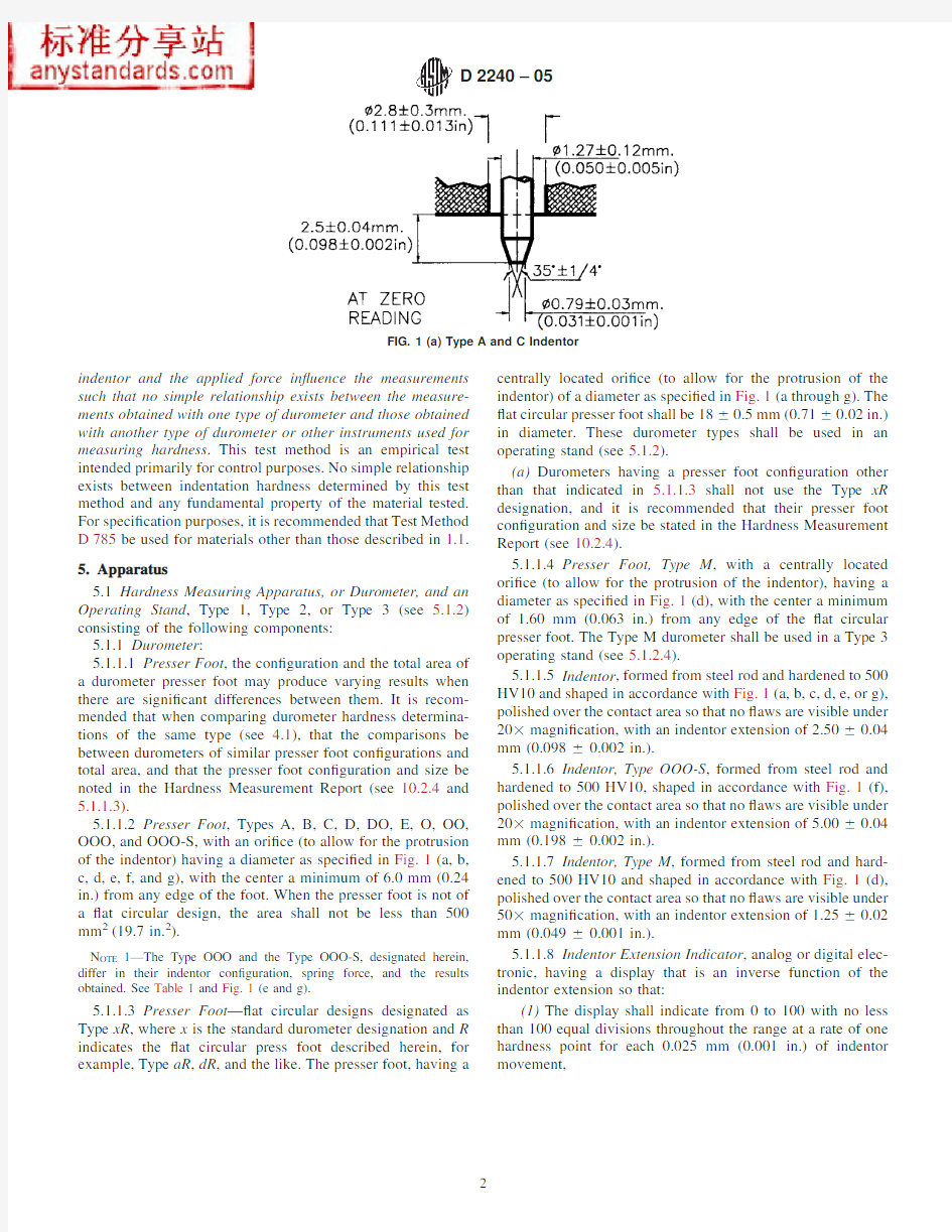
5.1.1.5Indentor ,formed from steel rod and hardened to 500HV10and shaped in accordance with Fig.1(a,b,c,d,e,or g),polished over the contact area so that no ?aws are visible under 203magni?cation,with an indentor extension of 2.5060.04mm (0.09860.002in.).
5.1.1.6Indentor,Type OOO-S ,formed from steel rod and hardened to 500HV10,shaped in accordance with Fig.1(f),polished over the contact area so that no ?aws are visible under 203magni?cation,with an indentor extension of 5.0060.04mm (0.19860.002in.).
5.1.1.7Indentor,Type M ,formed from steel rod and hard-ened to 500HV10and shaped in accordance with Fig.1(d),polished over the contact area so that no ?aws are visible under 503magni?cation,with an indentor extension of 1.2560.02mm (0.04960.001in.).
5.1.1.8Indentor Extension Indicator ,analog or digital elec-tronic,having a display that is an inverse function of the indentor extension so that:
(1)The display shall indicate from 0to 100with no less than 100equal divisions throughout the range at a rate of one hardness point for each 0.025mm (0.001in.)of indentor
movement,
FIG.1(a)Type A and C
Indentor
(2)The display for Type OOO-S durometers shall indicate from 0to 100with no less than 100equal divisions throughout the range at a rate of one hardness point for each 0.050mm (0.002in.)of indentor movement,
(3)The display for Type M durometers shall indicate from 0to 100with no less than 100equal divisions at a rate of one hardness point for each 0.0125mm (0.0005in.)of indentor movement,and
(4)In the case of analog dial indicators having a display of 360°,the points indicating 0and 100may be at the same point on the dial and indicate 0,100,or both.
5.1.1.9Timing Device (optional),capable of being set to a desired elapsed time,signaling the operator or holding the
hardness reading when the desired elapsed time has been reached.The timer shall be automatically activated when the presser foot is in contact with the specimen being tested,for example,the initial indentor travel has ceased.Digital elec-tronic durometers may be equipped with electronic timing devices that shall not affect the indicated reading or determi-nations attained by more than one-half of the calibration tolerance stated in Table 1.
5.1.1.10Maximum Indicators (optional),maximum indicat-ing pointers are auxiliary analog indicating hands designed to remain at the maximum hardness value attained until reset
by
FIG.1(b)Type B and D Indentor
(continued)
FIG.1(c)Type O,DO,and OO Indentor
(continued)
FIG.1(d)Type M Indentor
(continued)
the operator.Electronic maximum indicators are digital dis-plays electronically indicating and maintaining the maximum value hardness valued achieved until reset by the operator.5.1.1.11Analog maximum indicating pointers have been shown to have a nominal effect on the values attained,however,this effect is greater on durometers of lesser total mainspring loads;for example,the effect of a maximum indicating pointer on Type D durometer determinations will be less than those determinations achieved using a Type A durometer.Analog style durometers may be equipped with maximum indicating pointers.The effect of a maximum indicating pointer shall be noted at the time of calibration in the calibration report (see 10.1.5),and when reporting hardness determinations (see 10.2.4).Analog Type M,OO,OOO,and Type OOO-S durometers shall not be equipped with maximum indicating pointers.
5.1.1.12Digital electronic durometers may be equipped with electronic maximum indicators that shall not affect the indicated reading or determinations attained by more than one half of the spring calibration tolerance stated in Table 1.
5.1.1.13Calibrated Spring ,for applying force to the inden-tor,in accordance with Fig.1(a through g)and capable of applying the forces as speci?ed in Table 1.5.1.2Operating Stand (Fig.2):
5.1.2.1Type 1,Type 2,and Type 3shall be capable of supporting the durometer presser foot surface parallel to the specimen support table (Fig.3)throughout the travel of each.The durometer presser foot to specimen support table parallel-ism shall be veri?ed each time the test specimen support table is adjusted to accommodate specimens of varying dimensions.This may be accomplished by applying the durometer presser foot to the point of contact with the specimen support table and making adjustments by way of the durometer mounting assem-bly or as speci?ed by the manufacturer.
5.1.2.2Operating Stand,Type 1(specimen to indentor type),shall be capable of applying the specimen to the indentor in a manner that minimizes shock.
5.1.2.3Operating Stand,Type 2(indentor to specimen type),shall be capable of controlling the rate of descent of the indentor to the specimen at a maximum of 3.20mm/s
(0.125
FIG.1(e)Type OOO Indentor
(continued)
FIG.1(f)Type OOO-S Indentor
(continued)
in./s)and applying a force sufficient to overcome the calibrated spring force as shown in Table 1.
5.1.2.4Operating Stand,Type 3(indentor to specimen type),hydraulic dampening,pneumatic dampening,or electro-mechanical (required for the operation of Type M durometers)shall be capable of controlling the rate of descent of the indentor to the specimen at a maximum of 3.2mm/s (0.125in./s)and applying a force sufficient to overcome the calibrated spring force as shown in Table 1.Manual application,Type 1or Type 2operating stands are not acceptable for Type M durometer operation.
5.1.2.5The entire instrument should be plumb and level,and resting on a surface that will minimize vibration.Operating the instrument under adverse conditions will negatively affect the determinations attained.
5.1.2.6Specimen Support Table ,(Fig.3)integral to the operating stand,and having a solid ?at surface.The specimen support platform may have ori?ces designed to accept various inserts or support ?xtures (Fig.3)to provide for the support of irregularly con?gured specimens.When inserts are used to support test specimens,care must be taken to align the indentor to the center of the insert,or the point at which the indentor is to contact the specimen.Care should be exercised to assure that
the indentor does not abruptly contact the specimen support table as damage to the indentor may result.6.Test Specimen
6.1The test specimen,herein referred to as “specimen”or “test specimen”interchangeably,shall be at least 6.0mm (0.24in.)in thickness unless it is known that results equivalent to the 6.0-mm (0.24-in.)values are obtained with a thinner specimen.6.1.1A specimen may be composed of plied pieces to obtain the necessary thickness,but determinations made on such specimens may not agree with those made on solid specimens,as the surfaces of the plied specimens may not be in complete contact.The lateral dimensions of the specimen shall be sufficient to permit measurements at least 12.0mm (0.48in.)from any edge,unless it is known that identical results are obtained when measurements are made at a lesser distance from an edge.
6.1.2The surfaces of the specimen shall be ?at and parallel over an area to permit the presser foot to contact the specimen over an area having a radius of at least 6.0mm (0.24in.)from the indentor point.The specimen shall be suitably supported to provide for positioning and stability.A suitable
hardness
FIG.1(g)Type E Indentor (continued)TABLE 1Durometer Spring Force Calibration A
All Values are in N
Indicated Value Type A,B,E,O Type C,D,DO Type M Type OO,OOO Type OOO-S 00.5500.3240.2030.16710 1.3 4.4450.3680.2940.34320 2.058.890.4120.3850.52030 2.813.3350.4560.4760.69640 3.5517.780.50.5660.87350 4.322.2250.5440.657 1.04960 5.0526.670.5890.748 1.22670 5.831.1150.6330.839 1.40280 6.5535.560.6770.93 1.579907.340.0050.721 1.02 1.755100
8.0544.450.765 1.111 1.932N/durometer unit 0.0750.44450.00440.009080.01765Spring Calibration Tolerance
60.075N
60.4445N
60.0176N
60.0182N
60.0353N
A
Refer to 5.1.1.3for the Type xR
designation.
determination cannot be made on an uneven or rough point of contact with the indentor.
6.2Type OOO,OOO-S,and M test specimens should be at least 1.25mm (0.05in.)in thickness,unless it is known that
results equivalent to the 1.25-mm (0.05-in.)values are obtained with a thinner specimen.
6.2.1A Type M specimen that is not of a con?guration described in 6.2.2may be composed of plied pieces to
obtain
FIG.2Durometer Operating
Stand
FIG.3Small Specimen Support
Table
the necessary thickness,but determinations made on such specimens may not agree with those made on solid specimens because the surfaces of the plied specimens may not be in complete contact.The lateral dimensions of the specimen should be sufficient to permit measurements at least 2.50mm (0.10in.)from any edge unless it is known that identical results are obtained when measurements are made at lesser distance from an edge.A suitable hardness determination cannot be made on an uneven or rough point of contact with the indentor.6.2.2The Type M specimen,when con?gured as an o-ring,circular band,or other irregular shape shall be at least 1.25mm (0.05in.)in cross-sectional diameter,unless it is known that results equivalent to the 1.25-mm (0.05-in.)values are obtained with a thinner specimen.The specimen shall be suitably supported in a ?xture (Fig.3)to provide for positioning and stability.
6.3The minimum requirement for the thickness of the specimen is dependent on the extent of penetration of the indentor into the specimen;for example,thinner specimens may be used for materials having higher hardness values.The minimum distance from the edge at which measurements may be made likewise decreases as the hardness increases.
7.Calibration
7.1Indentor Extension Adjustment Procedure :
7.1.1Place precision ground dimensional blocks (Grade B or better)on the support table and beneath the durometer presser foot and indentor.Arrange the blocks so that the durometer presser foot contacts the larger block(s)and the indentor tip just contacts the smaller block (Fig.4).It is necessary to observe the arrangement of the blocks and the presser foot/indentor under a minimum of 203magni?cation to assure proper alignment.
7.1.2Indentor extension and shape shall be in accordance with 5.1.1.5,5.1.1.6,or 5.1.1.7,respective to durometer type.See Fig.1(a through g).Examination of the indentor under 203magni?cation,503for Type M indentors,is required to examine the indentor condition.Misshapen or damaged inden-tors shall be replaced.
7.1.3A combination of dimensional gage blocks shall be used to achieve a difference of 2.54+0.00/–0.0254mm (0.100+0.00/–0.001in.)between them.For Type OOO-S durometers,the gage block dimensions are 5.08+0.00/–0.0508mm (0.200+0.00/–0.002in.).For Type M durometers,the gage block
dimensions are 1.27+0.0/–0.0127mm (0.050+0.00/–0.0005in.)between them (Fig.4).
7.1.4Carefully lower the durometer presser foot until it contacts the largest dimensional block(s),the indentor tip should just contact the smaller block,verifying full indentor extension.
7.1.5Adjust the indentor extension to 2.5060.04mm (0.09860.002in.).For Type OOO-S durometers,adjust the indentor extension to 5.060.04mm (0.19860.002in.).For Type M durometers,adjust the indentor extension to 1.2560.02mm (0.04960.001in.),following the manufacturer’s recommended procedure.
7.1.5.1When performing the procedures in 7.1,care should be used so as not to cause damage to the indentor tip.Fig.4depicts a suitable arrangement for gaging indentor extension.7.1.6Parallelism of the durometer presser foot to the support surface,and hence the dimensional gage blocks,at the time of instrument calibration,may be in accordance with Test Methods D 374,Machinist’s Micrometers,or otherwise ac-complished in accordance with the procedures speci?ed by the manufacturer.
7.2Indentor Display Adjustment :
7.2.1After adjusting the indentor extension as indicated in 7.1,use a similar arrangement of dimensional gage blocks to verify the linear relationship between indentor travel and indicated display at two points:0and 100.Following the manufacturer’s recommendations,make adjustments so that:7.2.2The indicator displays a value equal to the indentor travel measured to within:
–0.0+1.0durometer units measured at 0;60.50durometer units measured at 100;
61durometer units at all other points delineated in 7.4.7.2.3Each durometer point indicated is equal to 0.025mm (0.001in.)of indentor travel,except for:
7.2.3.1Type M Durometers,each indicated point is equal to 0.0125mm (0.0005in.)of indentor travel;
7.2.3.2Type OOO-S Durometers,each indicated point is equal to 0.050mm (0.002in.)of indentor travel.
7.2.4The indicator shall not display a value greater than 100or less than 0at the time of calibration.
7.2.5Other means of determining indentor extension or indentor travel,such as optical or laser measurement methods,are acceptable.The instrumentation used shall have traceability as described in 1.4.
7.2.6The durometer shall be supported in a suitable fashion when performing the procedures described in 7.1and 7.2.7.3Calibration Device :
7.3.1The durometer spring shall be calibrated by support-ing the durometer in a calibrating device,see Fig.5,in a vertical position and applying a measurable force to the indentor tip.The force may be measured by means of a balance as depicted in Fig.5,or an electronic force cell.The calibrating device shall be capable of measuring applied force to within 0.5%of the maximum spring force necessary to achieve 100durometer units.
7.3.2Care should be taken to ensure that the force is applied vertically to the indentor tip,as lateral force will cause errors in calibration.See 7.1.5.1and 7.1.6
.
FIG.4Detail of Indentor Extension and Display
Adjustment
7.4Spring Calibration —The durometer spring shall be calibrated at displayed readings of 10,20,30,40,50,60,70,80,and 90.The measured force (9.83mass in kilograms)shall be within the spring calibration tolerance speci?ed in Table 1.Table 1identi?es the measured force applied to the indentor for the entire range of the instrument,although it is necessary only to verify the spring calibration at points listed herein.7.5Spring Calibration Procedure :
7.5.1Ensure that the indentor extension has been adjusted in accordance with 7.1,and the linear relationship between indentor travel and display is as speci?ed in 7.2.
7.5.2Place the durometer in the calibration device as depicted in Fig.5.Apply the forces indicated in Table 1so that forces applied are aligned with the centerline of the indentor in a fashion that eliminates shock or vibration and adjust the durometer according to manufacturers’recommendations so that:
7.5.3At the points enumerated in 7.4,the display shall indicate a value equal to 0.025mm (0.001in.)of indentor travel.For Type OOO-S durometers,the display shall indicate a value equal to 0.05mm (0.002in.)of indentor travel.For Type M durometers,the display shall indicate a value equal to 0.0125mm (0.0005in.)of indentor travel within the spring calibration tolerances speci?ed in 7.6.
7.6Spring calibration tolerances are 61.0durometer units for Types A,B,C,D,E,O,and DO,62.0durometer units for Types OO,OOO,and OOO-S,and 64.0durometer units for Type M,while not indicating below 0or above 100at the time of calibration (see Table 1).
7.7Spring Force Combinations :
7.7.1For Type A,B,E,and O durometers:Force,N =0.55+0.075HA
Where HA =hardness reading on Type A,B,E,and O durometers.
7.7.2For Type C,D,and DO durometers:Force,N =0.4445HD
Where HD =hardness reading on Type C,D,and DO durometers.
7.7.3For Type M durometers:Force,N =0.324+0.0044HM
Where HM =hardness reading on Type M durometers.
7.7.4For Type OO and OOO durometers:Force,N =0.203+0.00908HOO
Where HOO =hardness reading on Type OO durometers.7.7.5For Type OOO-S durometers:
Force,N =0.167+0.01765HOOO-S
Where HOOO-S =hardness reading on Type OOO-S durometers.
7.8The rubber reference block(s)provided for verifying durometer operation and state of calibration are not to be relied upon as calibration standards.The calibration procedures outlined in Section 7are the only valid calibration procedures.7.8.1The use of metal reference blocks is no longer recommended (see Note 2).
7.9Verifying the state of durometer calibration,during routine use ,may be accomplished by:
7.9.1Verifying that the zero reading is no more than 1indicated point above zero,and not below zero (on durometers so equipped),when the durometer is positioned so that no external force is placed upon the indentor.
7.9.2Verifying that the 100reading is no more than 100and no less than 99when the durometer is positioned on a ?at surface of a non-metallic material so that the presser foot is in complete contact,causing the indentor to be fully retracted.7.9.2.1It is important that when performing the veri?cation of 100,as described in 7.9.2,that extreme care be taken so as to not cause damage to the indentor.Veri?cation of the 100value is not recommended for durometers having a spring force greater than 10N (Types C,D,and DO).
7.9.2.2When performing the veri?cation of 100,as de-scribed in 7.9.2,the non-metallic material shall be of a hardness value greater than 100of the type (scale)of the durometer being employed.Tempered glass of a thickness greater than 6.35mm (0.25in.)has been found satisfactory for this application.
7.9.3Verifying the displayed reading at any other point using commercially available rubber reference blocks which are certi?ed to a stated value of the type (scale)of the durometer being employed.The displayed value of the durom-eter should be within 62durometer points of the reference block’s stated value.
7.9.4Veri?cation of the zero and 100readings of a durom-eter provide reasonable assurance that the linear relationship between the indicated display and the durometer mechanism remain valid.
7.9.5Veri?cation of points between zero and 100provide reasonable assurance that the curvilinear relationship between the indicated display and the durometer mechanism remain valid.
7.9.6This is not a calibration procedure,it is a means by which a user may routinely verify that the durometer may be functioning correctly.(See Note 2.)
https://www.doczj.com/doc/b53632563.html,boratory Atmosphere and Test Specimen Conditioning
8.1Tests shall be conducted in the standard laboratory atmosphere,as de?ned in Practice D 618,Section 4.2.
8.2The instrument shall be maintained in the standard laboratory atmosphere,as de?ned in Practice D 618,Section 4.1,for 12h prior to performing a
test.
FIG.5Example of Durometer Calibration
Apparatus
8.3The specimen shall be conditioned in accordance with condition40/23exclusive of humidity control,as described in Practice D618,Section8.1,Procedure A and tested under the same conditions,exclusive of humidity control.
8.4These procedures may be modi?ed if agreed upon between laboratories or between supplier and user and are in accordance with alternative procedures identi?ed in Practice D618.
8.5No conclusive evaluation has been made on durometers at temperatures other than23.06 2.0°C(73.46 3.6°F). Conditioning at temperatures other than the above may show changes in calibration.Durometer use at temperatures other than the above should be decided locally(see Practice D1349).
9.Procedure
9.1Operating Stand Operation(Type3Operating Stand Required for Type M):
9.1.1Care shall be exercised to minimize the exposure of the instrument to environmental conditions that are adverse to the performance of the instrument,or adversely affect test results.
9.1.2Adjust the presser foot to support table parallelism as described in5.1.2.1.It is necessary to make this adjustment each time the support table is moved to accommodate speci-mens of varying dimensions.
9.1.3Prior to conducting a test,adjust the vertical distance from the presser foot to the contact surface of the test specimen to25.462.5mm(1.0060.100in.),unless it is known that identical results are obtained with presser foot at a greater or lesser vertical distance from the test specimen contact surface, or if otherwise stipulated by the manufacturer.
9.1.4Place the specimen on the specimen support table,in
a manner that the contact point of the indentor is in accordance with Section6,unless it is known that identical results are obtained when measurements are made with the indentor at a lesser distance from the edge of the test specimen.
9.1.5Actuate the release lever(Fig.2)of the operating stand or activate the electromechanical device,allowing the durometer to descend at a controlled rate and apply the presser foot to the specimen in accordance with5.1.2.In the case of “specimen to indentor”type operating stands,operate the lever or other mechanism to apply the specimen to the indentor in a manner that assures parallel contact of the specimen to the durometer presser foot without shock and with just sufficient force to overcome the calibrated spring force as shown in Table 1.
9.1.6An operating stand that applies the mass at a con-trolled rate of descent,without shock is mandatory for Type M durometers.Hand-held application or the use of a Type1or Type2operating stand for the Type M durometer is not an acceptable practice,see5.1.2.4.
9.1.7For any material covered in1.1,once the presser foot is in contact with the specimen,for example,when the initial indentor travel has ceased,the maximum indicated reading shall be recorded.The time interval of1s,between initial indentor travel cessation and the recording of the indicated reading,shall be considered standard.Other time intervals, when agreed upon among laboratories or between supplier and user,may be used and reported accordingly.The indicated hardness reading may change with time.
9.1.7.1If the durometer is equipped with an electronic maximum indicator or timing device(refer to5.1.1.9)the indicated reading shall be recorded within160.3s of the cessation of indentor travel and reported(refer to10.2.9for reporting protocols),unless otherwise noted.
9.1.7.2If the durometer is equipped with an analog type maximum indicator(refer to5.1.1.10),the maximum indicated reading may be recorded and shall be reported(refer to10.2.9), unless otherwise noted.
9.1.7.3If the durometer is not equipped with the devices described in5.1.1.9or5.1.1.10,the indicated reading shall be recorded within1s as is possible and reported(refer to10.2.9), unless otherwise noted.
9.1.8Make?ve determinations of hardness at different positions on the specimen at least6.0mm(0.24in.)apart,0.80 mm(0.030in.)apart for Type M;and calculate the arithmetic mean,or alternatively calculate the median.The means of calculating the determinations shall be reported according to 10.2.8
9.2Manual(Hand Held)Operation of Durometer:
9.2.1Care shall be exercised to minimize the exposure of the instrument to environmental conditions that are adverse to the performance of the instrument,or adversely affect test results.
9.2.2Place the specimen on a?at,hard,horizontal surface. Hold the durometer in a vertical position with the indentor tip at a distance from any edge of the specimen as described in Section6,unless it is known that identical results are obtained when measurements are made with the indentor at a lesser distance.
9.2.3Apply the presser foot to the specimen,maintaining it in a vertical position keeping the presser foot parallel to the specimen,with a?rm smooth downward action that will avoid shock,rolling of the presser foot over the specimen,or the application of lateral force.Apply sufficient pressure to assure ?rm contact between the presser foot and the specimen.
9.2.4For any material covered in1.1,after the presser foot is in contact with the specimen,the indicated reading shall be recorded within160.1s,or after any period of time agreed upon among laboratories or between supplier and user.If the durometer is equipped with a maximum indicator,the maxi-mum indicated reading shall be recorded within160.1s of the cessation of initial indentor travel.The indicated hardness reading may change with time.
9.2.5Make?ve determinations of hardness at different positions on the specimen at least6.0mm(0.24in.)apart and calculate the arithmetic mean,or alternatively calculate the median.The means of calculating the determinations shall be reported according to10.2.8.
9.3It is acknowledged that durometer readings below20or above90are not considered reliable.It is suggested that readings in these ranges not be recorded.
9.4Manual operation(handheld)of a durometer will cause variations in the results attained.Improved repeatability may be obtained by using a mass,securely affixed to the durometer and centered on the axis of the indentor.Recommended
masses
are1kg for Type A,B,E,and O durometers,5kg for Type C, D,and DO durometers,and400g for Type OO,OOO,and OOO-S durometers.The introduction of an additional mass on Type M durometers is not permitted.Further improvement may be achieved by the use of a durometer operating stand that controls the rate of descent of the durometer presser foot to the test specimen and incorporates the masses described above.
10.Report
10.1Instrument Calibration Report(Durometer or Operat-ing Stand):
10.1.1Date of calibration.
10.1.2Date of last calibration.
10.1.3Calibration due date(see Note2).
10.1.4Manufacturer,type,model,and serial number of the instrument,and a notation when a maximum indicator or timing device is present.
10.1.5Values obtained(pre-and post-calibration results), including a notation of the effect of a maximum indicator,if present.The method of reporting the calibrated value shall be by attaining the arithmetic mean of the determinations.
10.1.6Ambient temperature.
10.1.7Relative humidity.
10.1.8Technician identi?cation.
10.1.9Applicable standards to which the instrument is calibrated.
10.1.10Calibrating instrument information to include type, serial number,manufacturer,date of last calibration,calibration due date(see Note2),and a statement of traceability of standards used to NIST or other acceptable organization.See 1.4.
10.2Hardness Measurement Report:
10.2.1Date of test.
10.2.2Relative humidity.
10.2.3Ambient temperature.
10.2.4Manufacturer,type,and serial number of the durom-eter or operating stand,or both,including a notation when a maximum indicator or timing device is present,date of last calibration,and calibration due date(see Note2).
N OTE2—The calibration interval(calibration due date)for a durometer is to be determined by the user,based upon frequency of use,severity of conditions,environmental factors,and other variables.
Periodic checking of the operation and state of durometer calibration using commercially available rubber test blocks(refer to7.8),speci?cally designed for this purpose,is recommended.
An instrument that has been exposed to severe shock,is visibly damaged,produces test determinations more than2points different from calibrated rubber test blocks or other reference standard,or is otherwise suspected of unreliability,should be removed from service and returned to a quali?ed calibration facility.
A calibration interval of one year is recommended for durometer test blocks and durometer instruments that are infrequently used,more often for others.
The calibration interval for instruments and peripheral devices em-ployed in the calibration of durometers is to be determined by the calibration service provider.It is recommended that the protocols outlined in ISO/IEC17025,as required by the manufacturer,and those to which the service is provided,be followed.
10.2.5Means of testing,whether manual(hand held),Type 1operating stand(specimen to indentor),Type2operating stand(indentor to specimen type),or Type3operating stand (electromechanical or hydraulically dampened).
10.2.6Description of test specimen,including thickness, number of pieces plied if less than the thickness indicated in Section6,including the vulcanization date.
10.2.7Complete identi?cation of material tested.
10.2.8Hardness value obtained and method of calculation, either arithmetic mean or alternatively,the median.
TABLE2Type1Precision—Type M Durometer Method Material Within Laboratories Between Laboratories MEAN Sr A r B(r)C SR D R E(R)F 131.8 1.26 3.5811.24 3.7610.6333.41 240.8 1.14 3.237.90 2.477.0017.13 354.00.975 2.76 5.11 2.38 6.7312.46 462.80.782 2.21 3.52 2.24 6.3410.10 570.90.709 2.01 2.830.974 2.76 3.89 680.6 1.686 4.77 5.92 1.61 4.56 5.65 787.7 1.15 3.25 3.71 2.637.458.50 832.40.947 2.688.26 3.6410.2931.73 941.80.797 2.26 5.40 2.23 6.3115.11 1053.30.669 1.89 3.55 2.29 6.4912.17 1163.20.485 1.37 2.17 2.19 6.209.80 1269.60.737 2.09 3.000.99 2.80 4.02 1378.30.784 2.22 2.84 1.04 2.94 3.75 1487.6 1.121 3.17 3.62 2.657.498.55 1534.10.85 2.407.05 1.84 5.2015.25 1642.30.635 1.80 4.25 1.20 3.398.01 1754.60.56 1.59 2.90 2.15 6.0911.15 1862.9 1.12 3.17 5.04 1.47 4.16 6.61 1970.30.689 1.95 2.770.944 2.67 3.80 2081.70.483 1.37 1.67 1.10 3.10 3.80 2187.90.879 2.49 2.83 2.07 5.86 6.67 AVERAGE61.4
POOLED
VALUES
0.924 2.62 4.26 2.146 6.079.89
A Sr=repeatability standard deviation,measurement units.
B r=repeatability=2.833Sr,measurement units.
C(r)=repeatability,relative,(that is,in percent).
D SR=reproducibility standard deviation,measurement units.
E R=reproducibility=2.833SR,measurement units.
F(R)=reproducibility,relative,(that is,in percent).
TABLE3Type1Precision—Type A Durometer Method Material
Average
Level
Within Laboratories Between Laboratories
Sr A r B(r)C SR D R E(R)F 151.40.646 1.83 3.56 1.56 4.418.59 265.30.878 2.48 3.81 2.21 6.069.27 368.00.433 1.23 1.80 2.28 6.459.49 Pooled61.60.677 1.92 3.11 2.018 5.729.28
A Sr=repeatability standard deviation,measurement units.
B r=repeatability=2.833Sr,measurement units.
C(r)=repeatability,relative,(that is,in percent).
D SR=reproducibility standard deviation,measurement units.
E R=reproducibility=2.833SR,measurement units.
F(R)=reproducibility,relative,(that is,in percent).
TABLE4Type1Precision—Type D Durometer Method Material
Average
Level
Within Laboratories Between Laboratories
Sr A r B(r)C SR D R E(R)F 142.60.3160.894 2.10 2.827.9818.7 254.50.791 2.24 4.11 3.5410.018.4 382.3 1.01 2.86 3.47 3.5410.012.2 Pooled59.80.762 2.16 3.61 3.329.4015.7
A Sr=repeatability standard deviation,measurement units.
B r=repeatability=2.833Sr,measurement units.
C(r)=repeatability,relative,(that is,in percent).
D SR=reproducibility standard deviation,measurement units.
E R=reproducibility=2.833SR,measurement units.
F(R)=reproducibility,relative,(that is,in
percent).
10.2.9Indentation hardness time interval at which determi-nation was made.Readings may be reported in the form:M/60/1where M is the type of durometer,60the reading,and 1the time in seconds that the presser foot is in contact with the specimen or from an electronic timing device.
11.Precision and Bias
11.1These precision and bias statements have been pre-pared in accordance with Practice D 4483.Refer to this Practice for terminology and other testing and statistical concepts.
11.2The Type 1precision for the Type M method was determined from an interlaboratory program with 21materials of varying hardness,with six participating laboratories.Tests were conducted on two separate days in each laboratory for the Type M testing program.All materials were supplied from a single source,being those commonly supplied as reference materials with the instruments from the manufacturer.
11.3The precision results in this precision and bias section give an estimate of the precision of this test method with the materials (rubbers)used in the particular interlaboratory pro-gram as described above.The precision parameters should not be used for acceptance or rejection testing,or both,of any group of materials without documentation that they are appli-cable to those particular materials and the speci?c testing protocols that include this test method.
11.4The Type 1precision for both Type A and D methods was determined from an interlaboratory program with 3materials of varying hardness,with six participating laborato-ries.Tests were conducted on two separate days in each laboratory for both A and D testing programs.All materials were supplied from a single source.
11.5A test result for hardness,for Types A,D,and M,was the median of ?ve individual hardness readings on each day in each laboratory.
11.6Table 2shows the precision results for Type M method,4Table 3shows the precision results for Type A method,5and Table 4gives the precision results for Type D method.5
11.7Precision —The precision of this test method may be expressed in the format of the following statements which use as appropriate value r ,R ,(r),or (R),that is,that value to be used in decisions about test results (obtained with the test method).The appropriate value is that value of r or R associated with a mean level in Table 1closest to the mean level under consideration (at any given time,for any given material)in routine testing operations.
N OTE 3—A Type 1precision statement for Types E,OOO,OOO-S,and R have not yet been made available.
11.7.1Repeatability —The repeatability,r ,of these test methods has been established as the appropriate value tabu-lated in Tables 2-4.Two single test results,obtained under normal test method procedures,that differ by more than this tabulated r (for any given level)must be considered as derived from different or non-identical sample populations.
11.7.2Reproducibility —The reproducibility,R ,of these test methods has been established as the appropriate value tabu-lated in Tables 2-4.Two single test results obtained in two different laboratories,under normal test method procedures,that differ by more than the tabulated R (for any given level)must be considered to have come from different or non-identical sample populations.
11.7.3Repeatability and reproducibility are expressed as a percentage of the mean level,(r)and (R),and have equivalent application statements as above for r and R .For the (r)and (R)statements,the difference in the two single test results is expressed as a percentage of the arithmetic mean of the two test results.
11.8Bias —In test method terminology,bias is the differ-ence between an average test value and the reference (or true)test property value.Reference values do not exist for this test method since the value (of the test property)is exclusively de?ned by this test method.Bias,therefore cannot be deter-mined.12.Keywords
12.1durometer;durometer hardness;hardness;indentation hardness;micro durometer hardness
4
Supporting data have been ?led at ASTM International Headquarters and may be obtained by requesting Research Report RR:D11-1091.5
Supporting data have been ?led at ASTM International Headquarters and may be obtained by requesting Research Report RR:
D11-1029.
APPENDIXES
(Nonmandatory Information)
X1.DUROMETER SELECTION GUIDE X1.1The durometer selection guide is designed to assist in
the selection of the proper durometer type for various applica-
tions.
X1.2It is generally recognized that durometer hardness
determination below20and above90are unreliable.It is
recommended that the next lower or higher type(scale)be used
in these situations.
X1.3It is also recommended that,whenever possible,an
operating stand be employed in performing durometer hardness
tests.
X2.RELATED TEST METHODS2
C367Test Methods for Strength Properties of Prefabricated Architectural Acoustical Tile or Lay-In Ceiling Panels
C473Test Methods for Physical Testing of Gypsum Panel Products
C581Practice for Determining Chemical Resistance of Thermosetting Resins Used in Glass-Fiber-Reinforced Struc-tures Intended for Liquid Service
C661Test Method for Indentation Hardness of Elastomeric-Type Sealants by Means of a Durometer
C836Speci?cation for High Solids Content,Cold Liquid-Applied Elastomeric Waterproo?ng Membrane for Use with Separate Wearing Course
D461Test Methods for Felt
D531Test Method for Rubber Property—Pusey and Jones Indentation
D619Test Methods for Vulcanized Fibre Used for Electri-cal Insulation
D1037Test Methods for Evaluating Properties of Wood-Base Fiber and Particle Panel Materials
D1054Test Method for Rubber Property—Resilience Us-ing a Goodyear-Healey Rebound Pendulum
D1414Test Methods for Rubber O-Rings
D1474Test Methods for Indentation Hardness of Organic Coatings
D2134Test Method for Determining the Hardness of Or-ganic Coatings with a Sward-Type Hardness Rocker
D2287Speci?cation for Nonrigid Vinyl Chloride Polymer and Copolymer Molding and Extrusion Compounds
D2583Test Method for Indentation Hardness of Rigid Plastics by Means of a Barcol Impressor
TABLE X1.1Durometer Selection:Typical Uses
Type (Scale)Typical Examples of Materials Tested
Durometer Hardness
(Typical Uses)
A Soft vulcanized rubber,natural rubber,nitriles,thermoplastic
elastomers,?exible polyacrylics and thermosets,wax,felt,and
leathers
20–90A
B Moderately hard rubber,thermoplastic elastomers,paper products,
and?brous materials Above90A Below20D
C Medium-hard rubber,thermoplastic elastomers,medium-hard
plastics,and thermoplastics Above90B Below20D
D Hard rubber,thermoplastic elastomers,harder plastics,and rigid
thermoplastics
Above90A
DO Moderately hard rubber,thermoplastic elastomers,and very dense textile windings Above90C Below20D
M Thin,irregularly shaped rubber,thermoplastic elastomer,and plastic
specimens
20–85A
O Soft rubber,thermoplastic elastomers,very soft plastics and
thermoplastics,medium-density textile windings
Below20DO
OO Extremely soft rubber,thermoplastic elastomers,sponge,extremely
soft plastics and thermoplastics,foams,low-density textile windings,
human and animal tissue
Below20O
CF Composite foam materials,such as amusement ride safety cushions,vehicle seats,dashboards,headrests,armrests,and door panels
See Test Method F
1957
D2632Test Method for Rubber Property—Resilience by Vertical Rebound
D4289Test Method for Elastomer Compatibility of Lubri-cating Greases and Fluids
D5672Test Method for Flexible Cellular Materials Mea-surement of Indentation Force De?ection Using a25-mm (1-in.)De?ection Technique
D6546Test Methods for and Suggested Limits for Deter-mining Compatibility of Elastomer Seals for Industrial Hy-draulic Fluid Applications
F1151Test Method for Determining Variations in Hardness of Film Ribbon Pancakes
N OTE X2.1—The hardness testing of other nonmetallic materials may be under the jurisdiction of one or more ASTM committees;the respective committee should be contacted for speci?c information.
ASTM International takes no position respecting the validity of any patent rights asserted in connection with any item mentioned in this https://www.doczj.com/doc/b53632563.html,ers of this standard are expressly advised that determination of the validity of any such patent rights,and the risk of infringement of such rights,are entirely their own responsibility.
This standard is subject to revision at any time by the responsible technical committee and must be reviewed every?ve years and if not revised,either reapproved or withdrawn.Your comments are invited either for revision of this standard or for additional standards and should be addressed to ASTM International Headquarters.Your comments will receive careful consideration at a meeting of the responsible technical committee,which you may attend.If you feel that your comments have not received a fair hearing you should make your views known to the ASTM Committee on Standards,at the address shown below.
This standard is copyrighted by ASTM International,100Barr Harbor Drive,PO Box C700,West Conshohocken,PA19428-2959, United States.Individual reprints(single or multiple copies)of this standard may be obtained by contacting ASTM at the above address or at610-832-9585(phone),610-832-9555(fax),or service@https://www.doczj.com/doc/b53632563.html,(e-mail);or through the ASTM website
(https://www.doczj.com/doc/b53632563.html,).
邵氏A 、C 、D 硬度對照表-邵氏硬度 硬度是物质受压变形程度或抗刺穿能力的一种物理度量方式。硬度可分相对硬度和绝对硬度。绝对硬度一般在科学界使用, 生产实践中很少用到。我们通常使用硬度体系为相对的硬度,常用有以下几种标示方法:肖氏(也叫邵氏,邵尔,英文SHORE)、洛氏、布氏三种。邵氏一般用于橡胶类材料上。 邵氏硬度的测试方法:用邵氏硬度计插入被测材料,表盘上的指针通过弹簧与一个刺针相连,用针刺入被测物表面,表盘上所显示的数值即为硬度值。 洛氏硬度的测试方法:用试验钢球能在被测物上砸上痕迹时硬度计表盘上所显示的数值即为硬度值。洛氏硬度约是布氏硬度的十倍,两者一般用于金属材料上。 因测试方法不同邵氏硬度与洛氏硬度、布氏硬度没有换算方式,但用洛氏硬度计测过硬橡胶,当时数据是:邵氏硬度90 洛氏硬度27 。 邵氏硬度 是指用邵氏硬度计测出的值的读数,它的单位是“度”,其描述方法分A 、D 两种,分别代表不同的硬度范围,90度以下的用邵氏A 硬度计测试,并得出数据,90度及以上的用邵氏D 硬度计测试并得出数据,所以,一般来讲对于一个橡胶或塑料制品,在测试的时候,测试人员能根据经验进行测试前的预判,从而决定用邵氏A 硬度计还是用邵氏D 硬度计来进行测试。一般手感弹性比较大或者说偏软的制品,测试人员可以直接判断用邵氏A 硬度计测试,如:文具类胶水瓶,TPU TPR 塑料膜袋等制品。而手感基本没什么弹性或者说偏硬的就可以用邵氏D 硬度计进行测试,如:PC ABS PP 等制品。如果度数是邵氏Axx ,说明硬度相对不高,如果是邵氏Dxx 说明其硬度相对较高。 补充:邵氏的单位不够全面: 1.A 型的单位表达是:HA 2.D 型单位表达就是:HD 邵氏A 、C 、D 硬度对照表 邵氏硬度 D 邵氏硬度 C 邵氏硬度 A 聚合物种类 90 硬塑 86 83 中等硬度塑胶 80 77 74 70 65 95 60 93 98 软塑 55 89 96 50 80 94 42 70 90 38 65 86 橡胶 35 57 85 30 50 80 25 43 75 20 36 70 15 27 60 12 21 50 10 18 40 8 15 30 6.5 11 20 4 8 10 硬度, 工廠內一般為測試橡膠之俗語 HA:為A 型的單位 表達是:HA 表示範圍0-90HA
IRHD国际橡胶硬度计 IRHD国际橡胶硬度计又称为国际橡胶邵氏硬度计、IRHD国际橡胶硬度计价格、密封圈橡胶硬度计、O型圈国际硬度计、橡胶圈硬度计 产品名称:IRHD国际橡胶硬度计 ?IRHD国际橡胶硬度计是一种针对高弹性物体的硬度测 量方式。本产品能精密测量厚度在0.6mm的不规则形或 规则形橡胶圈,密封,垫圈等等。快速定位拉杆能让样 品更精准快速的定位,电子式的测试头带有电子显示屏 幕以及RS-232的数据传输界面,测试针更能够应需求来 做更换。 ? 一、产品简介 IRHD 国际橡胶硬度计是一种针对高弹性物体的硬度测量方式。本产品能精密测量厚度在0.6mm的不规则形或规则形橡胶圈,密封,垫圈等等。快速定位拉杆能让样品更精准快速的定位,电子式的测试头带有电子显示屏幕以及RS-232的数据传输界面,测试针更能够应需求来做更换。可另外选购的Barofix和Centrofix定位装置组可让橡胶圈或弹性胶管状的样品被更准确的定位来达到精准的测量结果。用户更能经由Hard Test软件(选购)在计算机上做数据管理和分析。全新概念的IRHD Compact III 是一台非常符合经济效益的半自动化硬度测量仪器。
感谢以下网站对本资料的大力支持: 测厚仪https://www.doczj.com/doc/b53632563.html, 超声波测厚仪https://www.doczj.com/doc/b53632563.html, 钢板测厚仪https://www.doczj.com/doc/b53632563.html, 金属测厚仪https://www.doczj.com/doc/b53632563.html, 管道测厚仪https://www.doczj.com/doc/b53632563.html, 钢管测厚仪https://www.doczj.com/doc/b53632563.html, 厚度测量仪https://www.doczj.com/doc/b53632563.html, 超声测厚仪https://www.doczj.com/doc/b53632563.html, 高温测厚仪https://www.doczj.com/doc/b53632563.html, 壁厚测量仪https://www.doczj.com/doc/b53632563.html, 覆层测厚仪https://www.doczj.com/doc/b53632563.html, 膜厚仪https://www.doczj.com/doc/b53632563.html, 涂层测厚仪https://www.doczj.com/doc/b53632563.html, 镀层测厚仪https://www.doczj.com/doc/b53632563.html, 油漆测厚仪https://www.doczj.com/doc/b53632563.html, 漆膜测厚仪https://www.doczj.com/doc/b53632563.html, 锌层测厚仪https://www.doczj.com/doc/b53632563.html, 防腐层测厚仪https://www.doczj.com/doc/b53632563.html, 麦考特测厚仪https://www.doczj.com/doc/b53632563.html, 尼克斯测厚仪https://www.doczj.com/doc/b53632563.html, 磁感应测厚仪https://www.doczj.com/doc/b53632563.html, 涡流测厚仪https://www.doczj.com/doc/b53632563.html, 膜厚测试仪https://www.doczj.com/doc/b53632563.html, 覆层测厚仪 https://www.doczj.com/doc/b53632563.html, 电镀层测厚仪https://www.doczj.com/doc/b53632563.html, 涂镀层测厚仪https://www.doczj.com/doc/b53632563.html, 镀锌层测厚仪https://www.doczj.com/doc/b53632563.html, 电解测厚仪https://www.doczj.com/doc/b53632563.html, 氧化膜测厚仪https://www.doczj.com/doc/b53632563.html, 磁性测厚仪https://www.doczj.com/doc/b53632563.html, 干膜测厚仪https://www.doczj.com/doc/b53632563.html, 湿膜测厚仪https://www.doczj.com/doc/b53632563.html, 镀铬测厚仪https://www.doczj.com/doc/b53632563.html, 超声波探伤仪https://www.doczj.com/doc/b53632563.html, 超声波探伤仪https://www.doczj.com/doc/b53632563.html, 超声探伤仪https://www.doczj.com/doc/b53632563.html, 数字超声波探伤仪https://www.doczj.com/doc/b53632563.html, 电火花检测仪https://www.doczj.com/doc/b53632563.html, 焊缝探伤仪https://www.doczj.com/doc/b53632563.html, 超声波探伤仪https://www.doczj.com/doc/b53632563.html, 金属探伤仪https://www.doczj.com/doc/b53632563.html, 便携式探伤仪https://www.doczj.com/doc/b53632563.html, 钢结构探伤仪https://www.doczj.com/doc/b53632563.html, 磁粉探伤仪https://www.doczj.com/doc/b53632563.html, 邵氏硬度计https://www.doczj.com/doc/b53632563.html, 橡胶硬度计https://www.doczj.com/doc/b53632563.html, 便携式硬度计https://www.doczj.com/doc/b53632563.html, 便携式硬度计https://www.doczj.com/doc/b53632563.html, 尼克斯测厚仪https://www.doczj.com/doc/b53632563.html, 里氏硬度计https://www.doczj.com/doc/b53632563.html, 轧辊硬度计https://www.doczj.com/doc/b53632563.html, 巴氏硬度计https://www.doczj.com/doc/b53632563.html, 韦氏硬度计https://www.doczj.com/doc/b53632563.html, w-20韦氏硬度计https://www.doczj.com/doc/b53632563.html, 模具硬度计https://www.doczj.com/doc/b53632563.html, 超声波硬度计https://www.doczj.com/doc/b53632563.html, 洛氏硬度计https://www.doczj.com/doc/b53632563.html, 金属硬度计https://www.doczj.com/doc/b53632563.html, 硬度测试仪https://www.doczj.com/doc/b53632563.html, 布氏硬度计https://www.doczj.com/doc/b53632563.html, 肖氏硬度计 https://www.doczj.com/doc/b53632563.html, 铸件硬度计https://www.doczj.com/doc/b53632563.html, 轧辊硬度计https://www.doczj.com/doc/b53632563.html, 硬度仪https://www.doczj.com/doc/b53632563.html, 钢板硬度计https://www.doczj.com/doc/b53632563.html, 铝合金硬度计https://www.doczj.com/doc/b53632563.html, 电火花检测仪https://www.doczj.com/doc/b53632563.html, 电火花检漏仪https://www.doczj.com/doc/b53632563.html, 电火花检测仪https://www.doczj.com/doc/b53632563.html, 漆膜划格器https://www.doczj.com/doc/b53632563.html, 表面粗糙度仪https://www.doczj.com/doc/b53632563.html, 粗糙度测量仪https://www.doczj.com/doc/b53632563.html, 粗糙度测试仪https://www.doczj.com/doc/b53632563.html, 喷砂粗糙度仪https://www.doczj.com/doc/b53632563.html, 光洁度仪https://www.doczj.com/doc/b53632563.html, 便携式粗糙度仪https://www.doczj.com/doc/b53632563.html, 粗糙度仪https://www.doczj.com/doc/b53632563.html, 附着力测试仪https://www.doczj.com/doc/b53632563.html, 百格刀测试https://www.doczj.com/doc/b53632563.html, 百格刀 https://www.doczj.com/doc/b53632563.html, LED观片灯https://www.doczj.com/doc/b53632563.html, 黑白密度计https://www.doczj.com/doc/b53632563.html, 光泽度仪https://www.doczj.com/doc/b53632563.html, 特价机票https://www.doczj.com/doc/b53632563.html, 无损检测资源网https://www.doczj.com/doc/b53632563.html, 无损检测仪器https://www.doczj.com/doc/b53632563.html,
橡胶材料的硬度-邵氏硬度详解(S h a r e A,S h o r e D,S h o r e 00)
肖氏硬度,Shore A , Shore D 和Shore 00 的区别(0) Albert F.Shore——英国人肖尔(Albert F.Shore) Shore——指代肖氏硬度或肖氏硬度 - Shore scleroscope hardness, 简称HS。表示材料硬度的一种标准。由英国人肖尔(Albert F.Shore)首先提出。 应用弹性回跳法将撞销从一定高度落到所试材料的表面上而发生回跳。撞销是一只具有尖端的小锥,尖端上常镶有金刚钻。用测得的撞销回跳的高度来表示硬度。 肖氏硬度试验是一种动态力试验,与布、洛、维等静态力试验法相比,准确度稍差,受测试时的垂直性,试样表面光洁度等因素的影响,数据分散性较大,其测试结果的比较只限于弹性模量相同的材料。它对试样的厚度和重量都有一定要求,不适于较薄和较小试样,但是它是一种轻便的手提式仪器,便于现场测试,其结构简单,便于操作,测试效率高。 肖氏硬度计适用于测定黑色金属和有色金属的肖氏硬度值。肖氏硬度计便于携带,特别适用于冶金、重型机械行业中的中大型工件,例如大型构件、铸件、锻件、曲轴、轧辊、特大型齿轮、机床导轨等工件。在橡胶、塑料行业中常称作邵氏硬度。 SHORE A和SHORE D的原理其实是一样的,都是在标准条件下将标准的压针压入标准试样的表面,考察压入的深度来衡量试样的硬度。区别在于压针的形状不同,SHORE A用的是圆台形的,而SHORE D则用的是圆锥形的。所以A用来测试软塑料、弹性体和橡胶材料,D用来硬塑料和高硬度的弹性体与橡胶材料;只是当A的测量值大于90时,改为D型的,而当D型的读数小于20时就用A型的。 SHORE A 10-90,当SHORE A <10时换SHORE OO 当SHORE A>90时候换SHORE D Shore A和Shoer 00 是两种型号的硬度计,Shore A是测试橡胶类的,Shoer 00 是测试低硬度发泡材料类的.两者没有换数公式.
塑胶邵氏硬度测量与常见硬度对照表精选文档 TTMS system office room 【TTMS16H-TTMS2A-TTMS8Q8-
邵氏硬度测量与常见硬度对照表 什么是硬度 是物质受压变形程度或抗刺穿能力的一种度量方式。硬度可分相对硬度和绝对硬度。绝对硬度一般在科学界使用,生产实践中很少用到。我们通常使用硬度体系为相对的硬度,常用有以下几种标示方法:肖氏(也叫邵氏,邵尔,英文SHORE)、洛氏、布氏三种。邵氏一般用于橡胶类材料上。 邵氏硬度的测试方法:用插入被测材料,表盘上的指针通过弹簧与一个刺针相连,用针刺入被测物表面,表盘上所显示的数值即为。的测试方法:用试验钢球能在被测物上砸上痕迹时硬度计表盘上所显示的数值即为硬度值。洛氏硬度约是布氏硬度的十倍,两者一般用于金属材料上。因测试方法不同邵氏硬度与洛氏硬度、没有换算方式,但用洛氏硬度计测过硬橡胶,当时数据是:邵氏硬度90 洛氏硬度27 。 邵氏硬度简介 一般手感弹性比较大或者说偏软的制品,测试人员可以直接判断用邵氏A硬度计测试,如:文具类胶水瓶,TPU TPR 塑料膜袋等制品。而手感基本没什么弹性或者说偏硬的就可以用邵氏D硬度计进行测试,如:PC ABS PP 等制品。如果度数是邵氏Axx,说明硬度相对不高,如果是邵氏Dxx说明其硬度相对较高。补充: 邵氏的单位不够全面: 型的单位表达是:HA 型单位表达就是:HD 邵氏硬度计 邵氏硬度计用途邵氏硬度计用于橡胶类产品邵氏硬度值测量。 邵氏硬度计(3张) 原理具有一定形状的钢制压针﹐在试验力作用下垂直压入试样表面﹐当压足表面与试样表面完全贴合时﹐压针尖端面相对压足平面有一定的伸出长度L(即压针扎进被测物的深度),以L值的大小来表征邵氏硬度的大小,L值越大﹐表示邵尔硬度越低﹐反之越高。我国在这方面标准采用HA和HD两种,其中HA为较软橡胶类硬度参数(采用35度锥角的压针),HD为较硬的橡胶或塑料硬度参数(采用30度锥角的压针)。计算公式为HA=100-L/和HD=100-L/。硬度计算公式 1.肖氏硬度(HS)=勃式硬度(BHN)/10+12 2.肖式硬度(HS)=洛式硬度(HRC)+15 3.勃式硬度(BHN)=?式硬度(HV) 4.洛式硬度(HRC)= 勃式硬度(BHN)/10-3 常见邵氏硬度值的对比: Bicycle gel seat 15-30 OO 20 OO Sorbothane 40 OO Sorbothane 30-70 A 橡皮筋25 A Door seal(车窗外侧密封条)55 A 汽车轮胎70 A Soft skateboard wheel(软滑板轮子78 A Hydraulic? 70-90 A Hard skateboard wheel(硬滑板轮子)98 A Ebonite Rubber 100 A Solid truck tires(固定卡车轮胎)50 D Hard hat(安全帽)75 D 橡胶硬度的测量 携带方便、结果简单、操作方便、测量迅速,特别适合于现场的硬度测定
TH200邵尔A硬度计 使用说明书 顾登实业(上海)有限公司 https://www.doczj.com/doc/b53632563.html,或https://www.doczj.com/doc/b53632563.html, 400-670-1199
目录∶ (3) 1.概述 (3) 1.1主要特点及使用范围 (3) 1.2基本原理 (4) 1.3基本配置及仪器各部分名称 (5) 2.技术参数 (5) 2.1性能指标 (5) 2.2主要功能 (5) 3.使用方法 (5) 3.1测量步骤 (5) 3.1.1功能设置 (7) 3.1.2开始测量 (8) 3.1.3与计算机通讯 (9) 4.保养与维修 (9) 4.1保养 (9) 4.2维修 (10) 附录:邵尔硬度试验误差分析
1.概述 1.1主要特点及使用范围 时代TH200邵氏A 硬度计(以下简称硬度计)是一种先进的一体化数显式硬度测量仪器,它集测量装置和数据处理于一体,具有结构紧凑﹑测值准确﹑携带方便、造型美观、重量轻和易于操作等优点,用RS232通讯电缆还可以与计算机进行通讯。它主要用来测定软塑料和常规硬度橡胶的硬度,例如:软橡胶﹑合成橡胶﹑打印胶辊、热塑性弹性体、皮革等,在塑料业、橡胶业以及其他化工行业有着广泛的应用。 1.2基本原理 具有一定形状的钢制压针﹐在试验力作用下垂直压入试样表面﹐当压足表面与试样表面完全贴合时﹐压针尖端面相对压足平面有一定的伸出长度L (见图1)﹐以L 值的大小来表征邵氏硬度的大小,L 值越大﹐表示邵尔硬度越低﹐反之越高。计算公式为 :HA=100- 。 式中HA 为邵氏A 硬度。 由公式可知﹐邵氏A 硬度与压针位移量有关。通过测量压针的位移量﹐即可计算出邵氏A 硬度值。本硬度计用传感器测量出压针位移量,再通过CPU 计算处理,得出邵氏A 硬度值。 本仪器符合以下标准: ?《邵氏硬度计》检定规程 JJG 304-89 ?《邵尔A 型橡胶袖珍硬度计技术条件》HG2369-92 ?《硫化橡胶邵尔A 硬度试验方法》GB/T 531-92 ? 美国标准《Standard Test Method for Rubber Property ─Durometer 025 .0L
备检试样的要求 指针式邵氏橡胶硬度计的正确使用方法和保养常识 目前国内最常用的邵氏硬度计就是两款指针式的邵氏橡胶硬度计 1)邵氏A型硬度计 2)邵氏D型硬度计 使用邵氏硬度计时,当A型硬度计示值低于10HA时是不准确的,测量结果不能使用。A型硬度计测量值超出90HA时推荐使用D型硬度计。但由于用户出于经济方面的考虑,普遍只买硬度计而不买定负荷架,所以新手往往操作不规范,导致试验结果有较大的偏差。如何正确的使用这两种硬度计呢?下文结合应用实际情况,提供以下方法供试验用户参考 1)橡胶的试样及试验温度要求;①、橡胶的试样厚度不小于6mm,宽度不小于15mm,长度不小于35mm,试样厚度不足6mm时,可用同样胶片重叠测定,但不超过3层。并要求胶片上下平行。②、检定时室温为23℃±5℃,检定前硬度计在此温度下至少存放1小时 2)塑料试样及试验温度要求;①、塑料试样为正方形,边长50mm、厚度6mm。也允许采用50×15mm的试样。②、在可能的情况下,试样在测试前应按照 GB/T2941-1991规定在实验室标准温度下进行调节。比对试验或系列试验必须在相同温度下进行。 3)橡胶及塑料试样表面均应光滑、平整、不应有机械损伤及杂质等缺陷。 测定前检查硬度计 测定前应检查指针在自由状态下应指向零位。如指针量偏离零位时,可以松动右上角压紧螺钉,转动表面,对准零位。然后将硬度计压在玻璃板上,压针端面与压足底面紧密接触于玻璃板上时,指针应指向100+/-0.5HA,如不指向100+/-0.5HA 时,可轻微按动压针几次,如仍不指100+/-0.5HA时,则此硬度计不能使用。如在邵氏硬度计测试机架上使用时,可拨动手柄,使工作台上升至定荷砝码抬起,使压针端面与压足平面紧密接触于玻璃工作台时,指针应指向100+/-0.5HA。如不指100+/-0.5HA时, 可调整工作台平面的调节螺钉,若调整后指针仍不指 100+/-0.5HA时,最好送生产单位调整为宜。 使用正确的测试方法 把试样放置在坚固的平面上,拿住硬度计,压足中孔的压针距离试块边缘至少 12mm,平稳地把压足压在试样上,不能有任何振动,并保持压足平行于试样表面,以使压针垂直地压入试样,所施加的力要刚好足以使压足和试样完全接触,除另有规定,必须在压足和试样完全按触后1秒内读数,如果是其他间隔时间读数则必须说明,在试样相距至少6mm的不同位置测量硬度值5次,取其平均值。 4、邵氏硬度计及相关附件的保养常识 1)定荷测定架上的升降小轴和工作台底部,请注意经常揩擦干净,涂少量防锈油,以防生锈。
肖氏硬度,Shore A , Shore D 和Shore 00 的区别(0) Albert F.Shore——英国人肖尔(Albert F.Shore) Shore——指代肖氏硬度或肖氏硬度 - Shore scleroscope hardness, 简称HS。表示材料硬度的一种标准。由英国人肖尔(Albert F.Shore)首先提出。 应用弹性回跳法将撞销从一定高度落到所试材料的表面上而发生回跳。撞销是一只具有尖端的小锥,尖端上常镶有金刚钻。用测得的撞销回跳的高度来表示硬度。 肖氏硬度试验是一种动态力试验,与布、洛、维等静态力试验法相比,准确度稍差,受测试时的垂直性,试样表面光洁度等因素的影响,数据分散性较大,其测试结果的比较只限于弹性模量相同的材料。它对试样的厚度和重量都有一定要求,不适于较薄和较小试样,但是它是一种轻便的手提式仪器,便于现场测试,其结构简单,便于操作,测试效率高。 肖氏硬度计适用于测定黑色金属和有色金属的肖氏硬度值。肖氏硬度计便于携带,特别适用于冶金、重型机械行业中的中大型工件,例如大型构件、铸件、锻件、曲轴、轧辊、特大型齿轮、机床导轨等工件。在橡胶、塑料行业中常称作邵氏硬度。 SHORE A和SHORE D的原理其实是一样的,都是在标准条件下将标准的压针压入标准试样的表面,考察压入的深度来衡量试样的硬度。区别在于压针的形状不同,SHORE A用的是圆台形的,而SHORE D则用的是圆锥形的。所以A用来测试软塑料、弹性体和橡胶材料,D用来硬塑料和高硬度的弹性体与橡胶材料;只是当A 的测量值大于90时,改为D型的,而当D型的读数小于20时就用A型的。 SHORE A 10-90,当SHORE A <10时换SHORE OO 当SHORE A>90时候换SHORE D Shore A和Shoer 00 是两种型号的硬度计,Shore A是测试橡胶类的,Shoer 00 是测试低硬度发泡材料类的.两者没有换数公式. 怎样理解塑料类材料的硬度(hardness) 硬度 (Hardness) 是指材料对压印、刮痕等外力的抵抗能力。根据试验方法不同有邵氏 (Shore) 硬度、布氏 (Brinell) 硬度、洛氏 (Rockwell) 硬度、莫氏(Mohs) 硬度、巴氏 (Barcol) 硬度、维氏 (Vichers) 硬度等。硬度的数值与硬度计类型有关,在常用的硬度计中,邵氏硬度计结构简单,适于生产检验. 邵氏硬度用于确定塑料或橡胶等软性材料的相对硬度 . 它测量了规定压针在指定压强和时间条件下的针入度 . 硬度值用来识别或指定特殊硬度的塑料,也可作为多批材料的质量控制
ASTM 标准代号:D 2240-97ε美国国家标准橡胶特性-(丢洛氏)硬度计测硬度1-的标准试验方法 本标准是以固定的标志编号D 2240;紧接在编号后面的数字表示最初采用的年份,或者若有修订版本的情况下数字表示最近修订的年份,括号内的数字表示最近批准的年份上标的ε表示最近修或批准而作了编辑上的改变 ε1注:脚注从1999年2月的注5中消去。 1. 适用范围 1.1 本试验方法涉及A、B、C、D、DO、E、M、O、OO、OOO、OOO-S和R等12种 (丢洛氏)硬度计和按橡胶、网状材料、弹性材料、热塑材料和某些硬塑料的分类来确定物质的压痕硬度的程序。 1.2本试验方法不适用于对纤维织物的试验。 1.3以SI单位标注的值应视为标准值,括号中的值仅供参考。 1.4本标准并不意味以表述了所有可能与使用有关的安全事宜。本标准的使用者有责任建立 相应的安全与健康操作规程,并在使用前确定规则对适用性的限制。 2 参考文献 2.1 ASTM 标准
D618 对被测塑料做空气调节处理的程序2 D785 对塑料和电气绝缘材料的洛氏硬度的试验方法2 D1349 橡胶的操作规程—试验时的标准温度3 D4483 在橡胶与炭黑行业确定试验法标准精确度的操作规程3 3 试验方法的小结 3.1 本试验方法允许在初始压痕时测定硬度,或者在印压一特定时间后进行硬度测定,可 两者兼而有之。 注1:当使用最大指针读数时,被用作确定初始硬度值的具有最大读数的指针难以测准稍低的读数。 1 本试验方法直接由ASTM“D-11橡胶标准委员会”属下的《D11.10的物理试验委员会》负责最新版本于 1997年2月10日通过批准,于1997年3月颁布。最初是以D2240-64T的形式颁布,上一期的版本为D2240-95 2摘自《ASTM标准年签》,第08.01卷。
邵氏硬度(HS)的测试方法:用邵氏硬度计插入被测材料,表盘上的指针通过弹簧与一个刺针相连,用针刺入被测物表面,表盘上所显示的数值即为硬度值。 邵氏一般用于橡胶类材料上,也叫橡胶硬度计,热塑性的也有,诸如弹性体之类的。邵氏硬度的测试方法:用邵氏硬度计插入被测材料,表盘上的指针通过弹簧与一个刺针相连,用针刺入被测物表面,表盘上所显示的数值即为硬度值。邵氏硬度分为邵氏A和邵氏D。用邵氏D表示的硬度较邵氏A硬。 例如: 时代TH210橡胶硬度计邵氏D型一体化数显式硬度测量仪器,TH210橡胶硬度计集测量装置和数据处理于一体,具有结构紧凑、测值准确、携带方便、造型美观、重量轻和易于操作携带等优点。它主要用来测定硬塑料和硬橡胶的硬度,例如:热塑性塑料、硬树脂、地板材料、保龄球等,特别适合于现场对橡胶和塑料成品的硬度测量。测量范围:0HD~1 00HD,测量误差:在20HD~90HD内, 误差≤±1HD;价格3600元 TH200橡胶硬度计邵氏A型携带方便、造型美观、重量轻、体积小等优点。能快速准确地进行塑料、软橡胶、合成橡胶、打印胶辊的测量。TH200橡胶硬度计在化工及橡胶业有着广泛的应用。测量范围:0~100HA;测量误差:在20~90HA内,HA≤±1度,连接RS232通讯电缆,能与计算机进行数据通讯,具有峰值销锁存、平均值计算及欠压报警功能,具有自动关机功能。价格2800元 强度与硬度之间的区别 金属材料在外力作用下抵抗永久变形和断裂的能力称为强度。按外力作用的性质不同,主要有屈服强度、抗拉强度、抗压强度、抗弯强度等,工程常用的是屈服强度和抗拉强度,这两个强度指标可通过拉伸试验测出 强度是指零件承受载荷后抵抗发生断裂或超过容许限度的残余变形的能力。也就是说,强度是衡量零件本身承载能力(即抵抗失效能力)的重要指标。强度是机械零部件首先应满足的基本要求。机械零件的强度一般可以分为静强度、疲劳强度(弯曲疲劳和接触疲劳等)、断裂强度、冲击强度、高温和低温强度、在腐蚀条件下的强度和蠕变、胶合强度等项目。强度的试验研究是综合性的研究,主要是通过其应力状态来研究零部件的受力状况以及预测破坏失效的条件和时机 材料局部抵抗硬物压入其表面的能力称为硬度。试验钢铁硬度的最普通方法是用锉刀在工件边缘上锉擦,由其表面所呈现的擦痕深浅以判定其硬度的高低。这种方法称为锉试法这种方法不太科学。用硬度试验机来试验比较准确,是现代试验硬度常用的方法。常用的硬度测定方法有布氏硬度、洛氏硬度和维氏硬度等测试方法 硬度是衡量金属材料软硬程度的一项重要的性能指标,它既可理解为是材料抵抗弹性变形、塑性变形或破坏的能力,也可表述为材料抵抗残余变形和反破坏的能力。硬度不是一个简单的物理概念,而是材料弹性、塑性、强度和韧性等力学性能的综合指标。硬度试验根据其测试方法的不同可分为静压法(如布氏硬度、洛氏硬度、维氏硬度等)、划痕法(如莫氏硬度)、回跳法(如肖氏硬度)及显微硬度、高温硬度等多种方法 HSA常用于检测软质塑料橡胶,HSD常用于检测硬质塑料橡胶,还有个HSC不怎么常用,HSA 测量值大于90的时候应该转为HS D进行检测了HSD 测量值小于20的时候应该转为HSA进行检测了 测定塑料在规定负荷和标准压痕器作用下,在规定施加内,压痕器的压针压入试样的深度称
橡胶材料的硬度邵氏硬度 详解 S h a r e A S h o r e D S h o r e Last revision date: 13 December 2020.
肖氏硬度,Shore A , Shore D 和Shore 00 的区别(0) Albert ——英国人肖尔(Albert ) Shore——指代肖氏硬度或肖氏硬度 - Shore scleroscope hardness, 简称HS。表示材料硬度的一种标准。由英国人肖尔(Albert 首先提出。 应用弹性回跳法将撞销从一定高度落到所试材料的表面上而发生回跳。撞销是一只具有尖端的小锥,尖端上常镶有金刚钻。用测得的撞销回跳的高度来表示硬度。 肖氏硬度试验是一种动态力试验,与布、洛、维等静态力试验法相比,准确度稍差,受测试时的垂直性,试样表面光洁度等因素的影响,数据分散性较大,其测试结果的比较只限于弹性模量相同的材料。它对试样的厚度和重量都有一定要求,不适于较薄和较小试样,但是它是一种轻便的手提式仪器,便于现场测试,其结构简单,便于操作,测试效率高。 肖氏硬度计适用于测定黑色金属和有色金属的肖氏硬度值。肖氏硬度计便于携带,特别适用于冶金、重型机械行业中的中大型工件,例如大型构件、铸件、锻件、曲轴、轧辊、特大型齿轮、机床导轨等工件。在橡胶、塑料行业中常称作邵氏硬度。 ? SHORE A和SHORE D的原理其实是一样的,都是在标准条件下将标准的压针压入标准试样的表面,考察压入的深度来衡量试样的硬度。区别在于压针的形状不同,SHORE A用的是圆台形的,而SHORE D则用的是圆锥形的。所以A用来测试软塑料、弹性体和橡胶材料,D用来硬塑料和高硬度的弹性体与橡胶材料;只是当A的测量值大于90时,改为D型的,而当D型的读数小于20时就用A型的。 ? SHORE A 10-90,当SHORE A <10时换SHORE OO 当SHORE A>90时候换SHORE D Shore A和Shoer 00 是两种型号的硬度计,Shore A是测试橡胶类的,Shoer 00 是测试低硬度发泡材料类的.两者没有换数公式. ?
橡胶、塑料辊(以下简称胶辊),是由圆柱型金属辊芯外包覆橡胶或塑料制成,根据使用要求,可以制成各种尺寸和硬度等级的胶辊。 1 范围 本标准规定了胶辊的硬度要求。 2 引用标准 下列标准所包含的条文,通过在本标准中引用而构成的条文。本标准出版时,所示版本均为有效。所有标准都会被修订,使 用本标准的各方应探讨实用下列标准最新版本的可能性。 GB 2941—91 橡胶试样环境调节和试验的标准温度、湿度及时间(eqv ISO 471:1983) HG/T 2413.1—92 胶辊标观硬度的测定赵氏(P.J )硬度计法(eqv ISO 7267-3:1988) HG/T 2413.2—92胶辊标观硬度的测定邵尔硬度计法(idt ISO 7267-2:1986) HG/T 2450—93胶辊标观硬度的测定橡胶国际硬度计法(idt ISO 7267-1:1986) 3 硬度规定 可经供需双方协商,选定下列一种硬度作为胶辊硬度: a 橡胶国际硬度(IRHD); b 邵尔硬度(少尔A或邵尔D); c 赵氏硬度(PJ). 由于硬度受温度的影响,必要时应规定测量温度。 注:
1 在IRHD、邵尔硬度、P.J测量值之间,存在着一定关系,IRHD与邵尔A硬度值基本相等,对一般精度哟要求的测量,可用邵尔A硬度计代替橡胶国际硬度计,但应注意,由于读数时间不同,测量时间不同; 2 所有手工操作的硬度计,读书受操作者影响,使用橡胶国际硬度及或赵氏硬度计,读数受加载速度和施加的力是否垂直的影响,使用弹簧式邵尔温度计,读数更多的与压力大小有关; 3 由于硬度是通过压痕来测量的,因此,橡胶、塑料厚度对硬度值有影响,在标准试验室条件下,包覆厚度符合以下规定时,测量的包覆材料硬度即为胶辊硬度。 a IRHD 0~50 IRHD:厚度≥9㎜; >50IRHD:厚度≥6㎜。 b邵尔硬度 0~50邵尔A:厚度≥9㎜; >50邵尔A、邵尔D:厚度≥6㎜。 C P.J >200P.J:厚度>18㎜; 100~200P.J:厚度≥12㎜; 40~100P.J:厚度≥9㎜; 0~40P.J:厚度≥6㎜。 4 硬度测量 4.1 方法
新材料科技有限公司企业标准 邵氏硬度测量的标准方法 (2007) 2007- 08 -01 发布 2007- 08 - 01 实施 新材料科技有限公司发布
邵氏硬度测量的标准方法 1 范围 本标准测试方法描述了shore A 与shore D 两种橡胶硬度的测试方法,叙述了测定热塑性聚氨酯弹性体,热固性聚氨酯弹性体的压痕硬度的测试步骤。本测试方法基于最初的压痕或特定时间后的压痕来测定硬度。 本标准不适用于涂覆纤维。 所有的用于测定重量、力或尺寸的材料、仪器和设备应该采用国家标准或国际上认同的标准进行使用前的校正确认。 本标准并不涉及所有的安全问题,即使涉及,也只是涉及同应用有关的安全问题。建立合适的安全和健康的操作方法是本标准使用者的一项责任。请在使用以前,制定相应的规章制度。 2 规范性引用文件 下列文件中的条款,通过在本标准中引用而成为本标准的条款。未注明制定年份的引用文件,其最新版本适合于本标准。 ASTM D3174 固体弹性绝缘材料的厚度测试方法 ASTM D1349 橡胶测试的标准温度操作 ASTM D1415 橡胶性能-国际硬度的测试方法 3意义和应用 这种测试方法是基于标准条件下,材料在一定的压力下压足的穿透深度,硬度值同穿透深度成反比,由材料的弹性模量和粘弹性能所决定。压痕的形状和施加的压力影响测定值。不同类型种类的硬度计测试的结果之间没有彼此对应关系存在。 4 设备 硬度测定设备(硬度计)和操作台主要包括以下部分:
硬度计: 硬度计压足中间有一个园孔,其空心距离压足边缘至少6MM。 硬度计压针由硬度为500HV10的硬质钢棒组成,接触表面光滑,在20倍的放大镜下观察没有可见的瑕疵。伸出长度为±0.04mm。 压针伸出指示器(模拟或者数电显示) 指示器同压针的伸长成反比,指示器范围0~100。每一个刻度范围对应的压针位移。 操作台: 保证尽可能小的振动条件下移动样品到压足。 控制一定的速率,移动压足到样品,最大速率不得超过s。应用一定的压力克服校正弹簧压力。 所有的设备必须垂直并且水平,为了减少振动,将其固定在一个底座上。其它不适合的条件下的操作将反面影响测定值。 样品支撑台同操作台是一个完整的整体,有一个水平的光滑表面。当使用插入孔固定测试样品,必须使压针同插入孔的中心或压针同样品的接触点连成一线。谨慎操作,不要使压针同样品支撑台猛烈接触,以免毁坏压针。 5测试样品 测试样品,厚度至少6mm,除非更薄的样品的测试结果同厚度大于6mm时的测试结果一致。 可以通过将样品叠加得到需要的厚度,但是要保证各个样品折叠后全面接触。横向长度至少距边缘12.0mm以保证准确测量。除非测得的值在更短的长度范围内可以得到同样的结果。 样品表面应该平滑并且同接触表面平行以使压足同样品之间有以压点为中心半径为6mm接触,样品应该被适当的固定并且保证一定的稳定性。压针同不平滑的或者粗糙的表面接触不能得到准确的测量结果。 样品所需的最小厚度由压针对于样品的穿透深度决定,例如:具有较高硬度的材料可以采用较薄的样品。随着硬度的增加,接触点距样品边缘的最小距离可以减小。
邵氏硬度测量与常见硬度对照表 什么是硬度 硬度是物质受压变形程度或抗刺穿能力的一种物理度量方式。硬度可分相对硬度和绝对硬度。绝对硬度一般在科学界使用,生产实践中很少用到。我们通常使用硬度体系为相对的硬度,常用有以下几种标示方法:肖氏(也叫邵氏,邵尔,英文SHORE)、洛氏、布氏三种。邵氏一般用于橡胶类材料上。 邵氏硬度的测试方法:用邵氏硬度计插入被测材料,表盘上的指针通过弹簧与一个刺针相连,用针刺入被测物表面,表盘上所显示的数值即为硬度值。洛氏硬度的测试方法:用试验钢球能在被测物上砸上痕迹时硬度计表盘上所显示的数值即为硬度值。洛氏硬度约是布氏硬度的十倍,两者一般用于金属材料上。因测试方法不同邵氏硬度与洛氏硬度、布氏硬度没有换算方式,但用洛氏硬度计测过硬橡胶,当时数据是:邵氏硬度90 洛氏硬度27 。 邵氏硬度简介 一般手感弹性比较大或者说偏软的制品,测试人员可以直接判断用邵氏A硬度计测试,如:文具类胶水瓶,TPU TPR 塑料膜袋等制品。而手感基本没什么弹性或者说偏硬的就可以用邵氏D硬度计进行测试,如:PC ABS PP 等制品。如果度数是邵氏Axx,说明硬度相对不高,如果是邵氏Dxx说明其硬度相对较高。补充: 邵氏的单位不够全面: 1.A型的单位表达是:HA 2.D型单位表达就是:HD 邵氏硬度计 邵氏硬度计用途邵氏硬度计用于橡胶类产品邵氏硬度值测量。 邵氏硬度计(3张) 原理具有一定形状的钢制压针﹐在试验力作用下垂直压入试样表面﹐当压足表面与试样表面完全贴合时﹐压针尖端面相对压足平面有一定的伸出长度L(即压针扎进被测物的深度),以L值的大小来表征邵氏硬度的大小,L值越大﹐表示邵尔硬度越低﹐反之越高。我国在这方面标准采用HA和HD两种,其中HA为较软橡胶类硬度参数(采用35度锥角的压针),HD为较硬的橡胶或塑料硬度参数(采用30度锥角的压针)。计算公式为HA=100-L/0.025和HD=100-L/0.025。硬度计算公式1.肖氏硬度(HS)=勃式硬度(BHN)/10+12 2.肖式硬度(HS)=洛式硬度(HRC)+15 3.勃式硬度(BHN)= 洛克式硬度(HV) 4.洛式硬度(HRC)= 勃式硬度(BHN)/10-3 常见邵氏硬度值的对比: Bicycle gel seat 15-30 OO 口香糖20 OO Sorbothane 40 OO Sorbothane 30-70 A 橡皮筋25 A Door seal(车窗外侧密封条)55 A 汽车轮胎70 A Soft skateboard wheel(软滑板轮子78 A Hydraulic O-ring70-90 A Hard skateboard wheel(硬滑板轮子)98 A Ebonite Rubber 100 A Solid truck tires(固定卡车轮胎)50 D
硬度测试 SGSxx材料实验室 材料抵抗更硬物压入其表面的能力,称为硬度。根据试验方法和适应范围的不同,硬度可分为布氏硬度、维氏硬度、洛氏硬度、显微维氏硬度等许多种。硬度不是一个单纯的物理量,而是反映弹性、强度与塑性等综合性能指标。 2.1xxA型硬度测试: 2.1.1测试须在标准状态下(23±2℃,50±5% R.H)进行,且测试前试片须在标准状态下放置40小时以上。 2.1.2将试片置于硬度试验机平台上。调整使压针头与试样表面距离 25.4± 2.5mm 2.1.3测定时压针须与试片垂直且与各边缘相距12mm以上。 2.1.4无冲击地使压针头压在试样上。 2.1.5待完全压下,与试片接触1秒内,立即读取刻度值到整数字并记录其结果。GB/T 2411和ISO 868可在15±1秒内立即读数。GB/T531测硫化橡胶3秒读数,热塑性橡胶15秒读数。 2.1.6量取5处且每处相距6mm以上。 2.1.7 ASTM D2240,GB/T 2411和ISO 868试验结果以5处硬度值之平均值表示。GB/T531测试结果取五个不同位置的测量点的中值。 2.1.8若试验结果低于10或高于90则不适用此硬度试验机。大于90时改用邵D型硬度计。 2.2xxD型硬度计: 2.2.1 ~
2.2.7同xxA。 2.2.8若试验结果低于20或高于90则不适用此硬度试验机。低于20时,改用邵A型硬度计。 参考文件Reference ASTM D2240-05 Standard Test Method for Rubber Property-Durometer Hardness ASTM D618-05 Practice for Conditioning Plastics and Electrical Insulating Materials for Testing.ASTM D1349-99 Practice for Rubber-Standard Temperatures for Testing ISO 291:2005, Plastics–Standard atmospheres for conditioning and testing ISO 868:2003 Plastics and ebonite–Determination of indentation hardness by means of a durometer (Shore hardness)GB/T 2411-1980塑料邵氏硬度试验方法 GB/T531-2008硫化橡胶或热塑性橡胶压入硬度试验方法第1部分: 邵氏硬度计法(邵尔硬度)其他相关技术信息可以找客服人员索取,SGS深圳材料实验室(请到百度上去搜素)。
邵氏A、C、D硬度对照表 邵氏硬度 D邵氏硬度 C邵氏硬度 A聚合物种类 90 硬塑 86 83 中等硬度塑胶 80 77 74 70 65 95 60 93 98 软塑 55 89 96 50 80 94 42 70 90 38 65 86 橡胶 35 57 85 30 50 80 25 43 75 20 36 70 15 27 60 12 21 50 10 18 40 8 15 30 6.5 11 20
4 8 10 邵氏硬度的单位 在标准JB/T 7757.2-2006中,硬度值的单位表示为:邵氏硬度(A)HSD,也就是说,其单位是HSD; 在标准GB/T 531.1-2008第9条中是这样表述的:"硬度测量结果分别用Shore A、Shore D、Shore AO和Shore AM单位表示"; 邵氏硬度单位是度。 少尔《邵尔》硬度是物质受压变形程度或抗刺穿能力的一种物理度量方式。 硬度可分相对硬度和绝对硬度。绝对硬度一般在科学界使用,生产实践中很少用到。 我们通常使用硬度体系为相对的硬度,常用有以下几种标示方法:肖氏(也叫邵氏,邵尔,英文SHORE)、洛氏、布氏三种。 邵氏一般用于橡胶类材料上。邵尔(Shore Hardness),常用的Shore A符号是HA,主要用于测量橡胶硬度。 邵氏硬度是指用邵氏硬度计测出的值的读数,它的单位是“度”,其描述方法分A、D两种,分别代表不同的硬度范围,90度以下的用邵氏A硬度计测试,并得出数据,90度及以上的用邵氏D硬度计测试并得出数据,所以,一般来讲对于一个橡胶或塑料制品,在测试的时候,测试人员能根据经验进行测试前的预判,从而决定用邵氏A硬度计还是用邵氏D硬度计来进行测试。 一般手感弹性比较大或者说偏软的制品,测试人员可以直接判断用邵氏A 硬度计测试,如:文具类胶水瓶,TPU TPR 塑料膜袋等制品。而手感基本没什么弹性或者说偏硬的就可以用邵氏D硬度计进行测试,如:PC ABS PP 等制品。 如果度数是邵氏Axx,说明硬度相对不高,如果是邵氏Dxx说明其硬度相对较高。