NarrowBody aircraft - pneumatic system supplies air to Air Condition System
- 格式:pdf
- 大小:3.29 MB
- 文档页数:25
航空专业术语缩写单词AA/CA/ICE ABS AC ACIA ACM ACMP ACN ACP ACSU ACT ACU ADC ADCU ADF ADG ADI ADM ADRP ADSADSHCADV AECU AFCS AGB AGC AGL AHC AHM AHRS AHSAIDAIL AIS 飞机防冰绝对的交流电异步通信接口转换器空气循环机交流马达泵飞机分类数字音频控制面板自动控制开关装置活动的空气调节装置大气数据计算机自动展开控制装置无线电罗盘空气驱动发电机姿态方向指示器大气数据模块大气数据参考面板大气数据系统大气数据传感器加热控制器高级音频电子控制装置自动飞行控制系统附件箱自动增益控制地平线上姿态和方向计算机姿态保持模式姿态和方向参考系统姿态方向系统飞机接口差异飞机安装延迟副翼音频合成系统AircraftAnti-IceAbsoluteAlternating CurrerntAsynchronous Communications Interface AdapterAir Cycle MachineAlternation Currert Motor PumpAireraft Classification NumberAudil Control PanelAudio Control Switching UnitActiveAir Conditioning UnitAir Data ComputerAutodeploy Control UnitAutomatic Direction FinderAir Driven GeneratorAttitude Director IndicatirAir Data ModuleAir Data Reference PanelAir Datd SystemAir Data Scndor Heater ControllersAdvanceAudio Electronic Control UnitAutomatic Flight Control SystemAccessory Gear BoxAutomatic Gain ControlAbove Ground LevelAttitude and Heading ComputerAttitude Hold ModeAttitude and Heading Reference SystemAttitude Heading SystemAircraft Interface DiscrepancyAireraft Installation DelayAileronAudio Ontegrating SystemALT ALTN ALTS ALTSEL AM AME AMMAMTOSSANT AOA AOGAPAPC/EPC APD/CL APPR APRAPUAR ARINC ARM ARP ASA ASCU ASIATCATCRBS ATE ATR ATS ATT AUTBB/C 高度交替高度选择高度预选调幅调幅等效飞机维护手册飞机维护任务指导支持系统天线缚着角(迎角)停机坪自动驾驶辅助动力备用电动接触器附带电动接触器进出面板和门部件位置接近自动电力贮存自动性能贮备辅助动力装置如所需的航空无线电公司飞机恢复手册机场参考点飞机分离保险防滑控制装置空速指示器空中交通控制自动配平空中交通雷达信标系统自动测试装置油门自动延迟空气涡轮起动机姿态自动调谐返回过程(逆程)回波(定位)AltitudeAlternateAltitude SelectAltitude PreselectAmplitude ModulationAmplitude Modulation EquivalentAircraft Mainterance ManualAircraft Mainterance Task Oriented SupportSystemAntennaAngle Of AttackAirctaft on GroundAutopilotAuxiliary PowerAuxiliary Power ContactorExternal Power ContactorAccess Panels and DoorsComponent LocationApproachAutomatic Power ReserveAutomatic Perfkrmance ReserveAuxiliary Power UnitAs RequiredAeronautical Radio OncorporatedAircraft Recovery ManualAirport Reference PointAircraft Separation AssuranceAircraft Control UnitAir Speed IndicatorAir Traffic ControlAutomatic TrimAir Traffic Control Radar Beacon SystemAutomatic Test EquipmentAutomatic Throttle RetarderAir Turbine StarterAttitudeAutomatic or AutotneBack Course (Localizer)Back Course (locaoizer)BARO BAT BCD BFO BIT BITE BL BNK BNR BPSU BRGBRTBTBR BTMS BTMU BUTE BZLC CAL CAPCASCB CBIT CBP CCP CCW CDH CDI CDP CDU CES CHR CKPT CKT CLM CLR CMA 气压电池十进制二进制表示法差频振荡器内置测试内置测试装置尾线倾斜二进制小数表示法刹车和位置传感装置轴承明亮的明亮汇流条连接断电继电器刹车测试监视系统刹车测试监视装置后缘上弯遮挡板校准获得机组警告系统断路器连续集成测试断路器面板方向控制面板须时针计数器静压差航向偏差显示压缩器释压控制显示装置加拿大航空装备说明书精密时针座舱电路爬高清除甚低频接收机Barometric PressureBatteryBinary Coded DecimalBeat FrequencyBuilt In TestBuilt In Test EquipmentButtock LineBankBinary Fractional NitationBrake and Position Sensor UnitBearingBrightBrightnessBus Tie Breaker RelayBrake Temperature Monitoring SystemBrake Temperature Monitoring UnitBent Up T railing EdgeBezelCalibrateCaptureCrew Alerting SystemCalibrated Air SpeedCircuit BreakerContinuous BITCircuit Breaker PanelCompass Control PanelCounter ClockwiseClearance Delivery HeadConrse Deviation IndicatorCompressor Discharge PressureControl Display PyessureCanadair Equipment SpecificationChronometerCockpitCircuitClimbClearVLF/Omega ReceiverCMM COMM CPAM CPC CPU CRS CRT CSD CSDBCSUCT CTA CTL CVRCW 部件维护手册通讯座舱增压装置座舱增压控制器中央处理器航道阴极射线管恒速传动装置柯林斯串行数据总线中央搭接组件外形测量组件控制变压器电流互感器组件控制;通讯/导航调谐装置座舱录音装置连续波须时针Component Maintenance ManualCommunicateonCabin Pressure Acpuisition ModuleCabin Pressure ControllerCentral Processing UnitCourseCathode Ray TubeConstant Speed DriveCollins Serial Data BusCentralized Strapping UnitConfiguration Strapping UnitControl TransformerCurrent Trandformer AssemblyControl;Comm/NAV Tuning UnitCockpit Voice RecorderContinuous WaveClockwiseDDA偏流角Drift AngleDADS数字式大气数据系统Digital Air Data SystemDB分贝DecibelDBU数据装载器Data Base UnitDC直流电Direct CurrentDCP显示控制面板Display Control PanelDCU数据集中装置Data Concentrator UnitDDM调幅度差Difference in Depth of Modulation DEG度DegreeDES下降DescendDEV偏差DeviationDG方位陀螺Directional GyroDH决断高度Decision HeightDIR直接DirectDISC断开DisconnectDIST距离DistanceDME测距机Distance Measuring Equipment DMEHLD测距机保持DME HoldDN放下DownDOT运输部门Department Of TransportDPDT双刀双掷开关Double Pole Double ThrowDPL DR DSABL DSDD DSP DSPL EEECP ECS ECU ED1 ED2 EDP EDU 零部件详表航迹推算法截止、不适用双面双密度数字信号处理器显示升降舵EICAS 控制面板环境控制系统电子控制系统EICAS1 主显示EICAS2 次显示发动机驱动器电子显示装置Detailed Parts ListDead ReckoningDosableDouble-Sided Double-DensityDigital Signal ProcessorDisplayElevatorEICAS Control PanelEnvironmental Control SystemElectronic Control UnitEICAS1 Primary DisplayEICAS2 Sexondary DisplayEngine Driven PumpElectronic Display UnitEEPROMEFDEFISEGT EHSVEICASELEC ELEVDLT EMETEMG EMFEMI ENABL ENGENTEPEPC EPRR EPTC ESSETETA 电力地可擦除可编程只读存储器电子飞行显示电子飞行仪表系统喷气温度电子液压伺服阀发动机指示与机组警告系统有关电的升降舵应急定位发射机应急电动势电磁干扰能够接合进入外部动力(外部电源)外部电源接头外部电源准备继电器主电源转换接触器重要已飞时间预计到达时间Electrically Erasable ProgrammableRead-Only MemoryElectronic Flight DisplayElectronic Flight Instrument SystemExhaust Gas TemperatureElectrohydraulic ServovalveEngine Indication and Crew Alerting SystemElectricalElevatorEmergency Locator TransmitterEmergencyElectromotive ForceElectromagnetic InterferenceEnableEngageEnterExternal PowerExternal Power ContactorExternal Power Ready RelayEssential Power Teansfer ContactorEssentialElapsed TimeEstimated Time of ArrivalETER EVMFF/CTL FARFCC FCDIAG FCINDEX FCPFCSFCUFDFDAU FDRFDU FECUFFFIMFIM CNTS FL FLTPLAN FMC FMCW FMS FQQCFRFSC FSCUGGGAGCD GCRGCS GCU GCNGLCGLC--GS 预计航线飞行时间发动机振动监测飞行控制联邦航空法规飞行控制计算机错误码诊断错误码索引飞行控制面板飞行控制系统燃油控制装置飞行指引飞行数据探测装置飞行数据记录器磁通量探测单元襟翼电子控制装置燃油流动故障隔离手册FIM 内容飞行高度飞行计划飞行管理计算机连续波调制飞行管理系统燃油计量器来自燃油系统计算机燃油系统计算机装置获得绕(复飞)发电机接触驱动器发电机控制继电器地面杂波抑制发电机控制装置发电机发电机线路接触器发电机线路接触器-发电机段Estimater Time En RouteEngine Vibuation MonitoringFlight ControlsFederal Aviation RegulationFlight Control ComputerFault Code DiagramFault Code IndexFlight Control PanelFoight Control SystemFuel Control UnitFlight DirectorFlight Data Acquisition UnitFlight Data RecorderFlux Detector UnitFlap Electronic Control UnitFuel FlowFault Isolation ManualFIM ContentsFlight LevelFlight PlanFlight Management ComputerFrequency Modulated Cpntinuous WaveFlight Management SystemFuel Quantity Qauging ControllerFromFuel System ComputerFuel System Computer UnitGainGo-AroundGenerator Cibtactor DriverGenerator Control RelayGround Clutter SuppressionGenerator Control UnitGeneratorGenerator Line ContactorGenerator Line Contctor-Generator SectionGLCR GLD GMT GND GPS GPWC GPWR GPWS GSG/S GTC GTCP GTOW H HDG HF HGC HGS HIRF HLD HOT HP HPA HR HIS HSTA HSTCS HSTCU HTR HYDII/O IAPS IAS IAW IBIT ICICC ICP 发电机线路接触器继电器发电机线路接触器格林威治标准时间地面全球位置系统近地警告计算机地面电源近地警告系统滑翔斜率地面速度发电机切换接触器喷气涡轮压缩器最大起飞重量航向高频抬头指引计算机抬头指引系统(平显)高强度辐射场保持高滑油温度高压百帕小时水平状态指示器水平安定面配平作动筒水平安定面配平控制系统水平安定面配平控制装置加热器液压输入/输出综合电子处理系统指示空速适合于起始位内话IAPS 插件箱机内通话控制面板Generator Line Contactor RelayGround Lift DumpingGreenwich Mean TimeGroundGlobal Position SystemGround Proimity Warning ComputerGround PowerGround Proximity Warning SystemGlidcslopeGround SpeedGenerator Transfer ContactorGas Turbine Compressor PneumaticGross Take-Off WeightHeadingHigh FrquencyHead-up Guidance ComputerHead-up Guidance SystemHigh Intensity Radiated FieldsHoldsHigh O il T emperatureHigh PressureHecto PascalsHourHorizontal Situation IndicatorHorizontal Stabilizer Trim ActuatorHorizontal Stabilizer Trim Control SystemHorizontal Stabo;ozer Tro, Control UnitHeaterHydraulicInput/OntputIntegrated Avionics Processor SystemIndicated AirspeedIn Accordance WithInitiater BitIntercomIAPS Card CageInterphone Control PanelICTA ICUIDIDG IDSIDX IECIEUIFIFFIGVILSIMIMT INBD INHM INPH INS INST INSTL INT/SVC INTEG INTLK IOCIPCIRCIRSIRUISA 仪表变流器组件机内通话控制盒识别整体驱动发电机仪表显示系统索引IAPS 环境控制器机内通话电子设备中频敌友识别进口导向器叶片仪表着陆系统内信标台仪表固定座内侧汞柱/英尺机内通话惯性导航系统仪表安装内话/开关音量控制完整的机内时钟输入/输出集合器部件图解分类仪表遥控惯性基准系统惯性基准装置国际标准大气温度Instri,emt Cirremt Tramsfpr,er AssemblyInterphone Control UnitIdentIntegrated Drive GeneratorInstrumcnt Display SystemIddexIAPS Environmental ControllerInterphone Electronics UnitIntermediate FrequencyIkentity Friend FoeInlert Guide VanesInstrument Ianding SystemInner MarkerInstrument Mounting TrayInboardInches of MercuryInterphoneInertial Navigation SystemInstrumentInstallationInterphone/Switch V olume ControlIntegralInterlockInprt/Outprut ConcentratorIllustrated Parts CatalogInstrument Remote ControlInertial Reference SystemInertial Reference UnitInternational Standard AtmosphereTemperatureISOLITTIVSIJJBJEMTOSSKKHZ 隔离Isolation内涡轮温度Interturbine Temperature惯性引导垂直分速显示器Inertial Lead Vertical Speed Indicator接线盒Junction Box喷气式发动机维护任务支Jet Engine Maintenance Task Oriented 持系统Support System千赫KilohertzKTS KVALLADV LAT LCD LCT LCTA LCVLDLDU LED LGCU LHLHP LOC LON LOP LPT LRM LRN LRU LSD LTRLV LVDT LVLCHG LWDMMAG MAN MAX MDA MDC MDU NEL MEM MES MFC 节千伏安线性上升纬度液晶显示线路互感器线路互感器组件负载控制阀下边带数据信号灯驱动装置发光二级管起落架控制装置左手雷电/高强度辐射保护当地时间经度低滑油压力低压力涡轮可快速更换部件大范围的领航(远程导航)线路可更换组件最小有效数字字母下边带线性变量差接变压器水平变化左翼下磁性的手册最大最小下滑高度维护诊断计算机人工释放装置最小设备清单内存模块主发动机起动机械燃油控制KnotsKilo V olt AmperesLine AdvanceLatitudeLiquid Crystal DisplayLine Current TransformerLine Current Transformer AssemblyLoad Control ValveLower Sideband DataLamp Driver UnitLight Emitting DiodeLanding Gear Control UnitLeft HandLightning/HIRF ProtectorLocal Time ,LocalizerLongitudeLow Oil PressureLow Pressure TurbineLine Replaceable ModuleLong-Range NavigationLine Replaceeable UnitLest Significant DigitLetterLover sideband V oiceLinear Variable Differential TransformerLevel ChangeLeft Wing DownMagneticManualMaximumMinimum Dedcent AltiudeMaintenance Diagnoetic ConputerManual Deployment UnitMinimum Equipment ListMemory ModuleMain Engine StartMechanical Fuel ControlMFD MGMT MIC MISC MLG MLI MLS MM MMEL MMO MSD MSG MSU MUX NNAV NCD NDB NEG NLG NORM NP NVI NVM OOM OVBD OVHT OVLD PPA PAA PAC PAU PBM PBSOV PCB PCU PDC 多功能显示管理话筒综合主起落架磁性水平指示器微波着陆系统中间信标台主最小设备清单最大马赫数大多数重要数字信息方式选择装置多路转换器导航无计算数据无方向信标台领航的前起落架正常的不可获得的无方向中断永久性内存外信标台机外过热过载旅客地址旅客地址放大器航迹衰减补偿便携式分析系统压力偏差调节停机刹车断流阀印刷线路板动力控制装置压力放出压缩器Multifunction DisplayManagementMicrophoneMiscellaneousMain Landing GearMagnetic Level IndicatersMicrowave Landing SystemMiddle MarkerMaster Minimum Equipment ListMach,Nax OperatingMost Sognificant DigitMessageMode Select UnitMultiplexerNavigationNo Computecd DataNon-Directional BeaconNegativeNose Landing GsarNormalNonprocurableNonvectored InterruptNonvolatile MemoryOuter MarkerOverboardOverheatOverloadPassenger AddressPassenger Assress AmplifierPath Attenuation CorrectionPortable Analysis UnitPressure Bias ModulationParking Brake Shutoff ValvePronted Corcuot BoardPower Cpntrol UnitPressure DisCharge CompressorPDU PEP PESOV PFCU PFD PIT PLA PMA PMG POC POR POS PPBM PPH PPIPR PRE PRI PROM PSEU PSI PSS PSU PTOPTTPVC PWR Q QRB RR/T RA RAC RAD RAM RAT RCCB RCIM 动力驱动装置峰值包线功率压力调节/断流阀俯仰感觉控制装置主飞行显示俯仰动力水平角部件制造厂永久磁铁发电机上电清除法规点位置(垂直流动)动力装置装配手册磅每小时计划位置指示器电源继电器预置主要的可编程只读存储器电子接近传感装置磅每平方英寸接近传感系统旅客服务装置动力起飞推—讲话按下—测试PVC 材料电源快卸扣收/发机无线电高度表无线电高度计算机径向的随机存储器涡轮喷气发动机远程控制线路断路器滚动控制输入模块Power Drive UnitPeak Envelope PowerPressure Regulating/Shutoff ValvePitch Feel Control UnitPrimary Flight DisplayPitchPower Lever AneratorPart Manufacturing AuthorixationPermanent Magnet GeneratorPower-On ClearPoint Of RegulationPosition(vertical scroll)Power Plant Buildup ManualPounds Per HourPlan Positiin IndicatorPower RelayPresetPriaryProgammable Read-Only MemoryProximity Sensor Electronic UnitPounds per Square InchProximity Sensor SystemPassenger Service UnitPower TakeoffPush-To-TalkPress-To-TestPolyvinyl ChloridePowerQuick-Release BucklcReceiver/TransmitterRadio AltitudeRadio Altimeter ComputerRadialRandom Access MemortRam Air TurbineRemote Control Circuit BreakerRoll Control Input ModuleRCP RCU RDR REL REV RFRHRMI RMS RMT ROL RPMR/S RSSRT RTN RTU RUD RVDT RWDSSASAI SAT SAW SBWSCDSDI SECU SEL SELCAL SMT SNSR SOV SPC SPD SPMSQ 远程补偿面板远程补偿装置雷达相关的回复无线电频率右手无线电磁指示器均值方根远程的滚动转每分钟复位/设置无线电传感器系统无线电传输返回无线电调谐装置方向舵循环变量差接变压器在右机翼下备用高度表备用空速指示器静压空气温度表面声波电操纵控制部分详图控制源图源/目标辨别器阻流板电子控制装置选择选择呼叫舵机固定盘传感器断流阀失速保护计算机速度冲程每分钟静噪Remote Compensation PanelRemote Compensation UnitRadarRelativeReversionRadio FrequencyRight HandRadio Magnetic IndicatorRoot Mean SquareRemoteRollRevolutions Per MinuteReset/SetRadio Sensor SystemRadio TransmitReturnRadio T uning UnitRudderRotary V ariable D ifferential T ransformerRight Wing D ownStandby AltimeterStandby Airspeed IndicatorStatic Air TemperatureSurface Acoustic WaveSteer-By-WireSpecification Control DrawingSonrce Cintril DrawingSouree/Destination IdwntifierSpoiler Electronic control UnitSelectSelective CallingServo Mounting TraySensorShutoff ValveStall Protedtion ConuterSpeedStrikes Per MinuteSquelchSRMSSSSMSSV STAB STAT STBY STC SVO SYNC SYSCTRL TT/RTATASTAT TCAS TCTATDTDR TFCTGTTOGA TRK TRU TTG TURB TWRTXU 结构修理手册失速速度信号状态系统简图手册电磁选择阀安定面状态备用灵敏度时间控制伺服非同步的系统控制反推交通警告真空速总空气温度交通警告和防撞系统连接电流互感器组件时间延迟应答机交通靶涡轮电动机气体温度起飞轨迹变压器整流器组件出发时间紊流气象雷达发射Structural Repair ManualStall SpeedSign Starys MatrixSystem Schematic ManualSolenoid Selector ValveStabilization ; StabilizerStatusStandbySensitivity Time ControlServoStncheonizeSystem ControlThrust ReverserTraffic AlertTrue AirspeedTotal Air TemperatureTraffic a lert a nd Collision Avoidance SystemTie Current Trandformer AssemblyTime DelayTransponderTrafficTargetTurbine Gas TemperatureTake Off Go AroundTrackTransformer Rectifier UnitTime To GoturbulenceTurbulenec Weather RadarTransmitUARTUD UHF UHLK ULD UMT 全球异步接收机/发射机上边带数据超高频解锁水下定位装置通用固定盘UniversalReceiver/TransmitterUpper Sideband DataUltra-High FrequencyUnlockUnderwater Locator DeviceUniversal Mounting TrayAsynchronousUSTB UTC UVVV1V2 VAC VDCVGVGD VHF VHS VMO VNAV VNRVOR 不安定的通用时间坐标上边带声音起飞决断速度起飞安全参考速度交流伏特直流伏特可变外形尺寸垂直罗盘变截面进气道甚高频超主速最大空速垂直导航VHF 导航接收机甚高频全方位天线电测向UnstabilizedUniversal Time CoordinatedUpper Sideband V oiceTakeoff Dexision Heught ReferenceAurspeedTakeoff Safety Speed Reference AirspeedVolts Alternating CurrentVots Sirect CurrentVariable GeometryVertical GyroVariavle Geometry DiffuserVery High FrequencyVery High SpeedAirspeed,Max OperatingVertical NavigationVHF Navigation ReceiverVHF Omnidirectional RangeW/LWM WOW WPT WR WRS WRP X XDCR XFER XTK YYD YDS MISC 水平线翼平线布线手册机轮承重道路气象雷达气象雷达系统气象雷达面板功率转送器电流转移十字交叉偏航阻尼器偏航阻尼器系统Water LineWing LeveWiring ManualWeight-On-WheclsWaypointWeather RadarWeather Radat SystemWeather Radat PanelTransducer CurrentTransferCrosstrackYaw DamperYaw Damper System 仪VS垂直速度Vertical SpeedVSI垂直速度指示器Vertical S peed I ndicator VSPDSW空速Airspeeds3CM 4POT ΔP 第三机组成员四刀双掷开关(ΔP)压差Third Crew MemberFour Pole Double Throw(DELTA P)Differential Pressure。
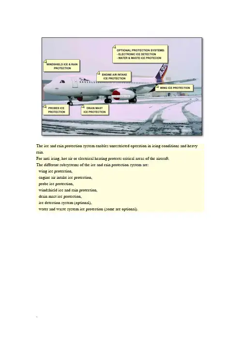
The ice and rain protection system enables unrestricted operation in icing conditions and heavy rain.For anti-icing, hot air or electrical heating protects critical areas of the aircraft.The different subsystems of the ice and rain protection system are:- wing ice protection,- engine air intake ice protection,- probe ice protection,- windshield ice and rain protection,- drain mast ice protection,- ice detection system (optional),- water and waste system ice protection (some are optional).Hot air from the pneumatic system is supplied for the anti-icing of the three outboard leading edge slats (3, 4 and 5) of each wing. Bleed air from the engines or the APU is supplied to each wing through a pressure regulating and shut off valve called Wing Anti-Ice (WAI) valve.A single P/BSW on the overhead ANTI ICE panel controls WAI supply to both wings. WAI must be manually selected by the crew and is available in flight only.Whenever WAI is selected, the engine idle is increased and the Takeoff/Go Around (TOGA) limit (max thrust) is decreased by the Full Authority Digital Engine Control (FADEC). This signal is sent to the FADEC through the Engine Interface Unit (EIU). WAI test limited to 30 seconds. Fortesting purposes, WAI can be selected on the ground but will be automatically limited to 30 seconds operation to prevent damage to the wing leading edge.Each engine air intake is protected from ice by an independent air bleed supply from the High Pressure (HP) compressor of that engine.The air is supplied through the engine air intake anti-ice valve.Engine anti-ice is manually selected by the crew and is available in flight or on the ground with the engine running. After circulating around the inlet, the air is ducted overboard.Note: In the event of an electrical power supply failure, this valve will automatically open when the engine is running.Whenever engine anti-ice is selected, the engine idle is increased and the TOGA limit (max thrust) is decreased by the FADEC. For V2500, the FADEC also turns on continuous ignition. This signal is sent to the FADEC through the EIU. The ignition is automatically on PW6000 and on V2500 engines. On CFM56 the IGN is not automatically on.Ice protection of the Angle Of Attack (AOA) sensors, pitot probes, static ports, and Total Air Temperature (TAT) probes is achieved by electrical heating.In order to give reliable information to the air data systems, the air data probes are heated automatically when at least one engine is running. The probes are arranged in three channels related to the three air data systems: CAPT, F/O and STBY (Air Data/Inertial Reference Unit (ADIRU) 1, 2, 3). The heating system for each channel is controlled by a Probe Heat Computer (PHC) 1, 2, 3.The PROBE/WINDOW HEAT P/BSW (normally in the AUTO position) may be used to select the probe heating ON with the engines shut down.Electrical heating is supplied for windshield anti-icing and cockpit side window de-fogging.The front windshields and side windows are heated automatically when at least one engine is running. The heating system for each side is controlled and monitored by a Window Heat Computer (WHC) 1, 2.The PROBE/WINDOW HEAT P/BSW (normally in the AUTO position) may be used to select the window heating ON with the engines shut down. The windows are protected against overheatby sensors and flight/ground logic. The sensors turn off the heat when the temperature reaches the limit and the windows are heated at a lower power on the ground than in flight.Rain removal from the windshield is ensured by tow independent wipers powered by DC motors. The wiper system is designed to work efficiently up to 200 knots.Each wiper is controlled by a rotary selector located on the overhead panel. "SLOW" or "FAST" speed can be selected. The selector switch can be optionally equipped with and "INTerMiTtent" position. During intermittent operation, the DC motor is assisted by a timer. When the selector is set to "OFF", the wiper stops in the parking position and is lifted off the aircraft structure, at the bottom part of the windshield.Do not operate the wipers in a dry windshield.Rain removal from the windshield is done by two independent wipers and by a rain repellent system in heavy rain. The wipers operate independently. The rain repellent is discharged onto the left or right windshield from a pressurized canister installed at the rear of the cockpit.There are two drain masts installed on the lower fuselage forward and aft sections.When the electrical system is powered, the waste water drain masts are also electrically heated. Two control units located in the cargo compartments control the heating of the forward and aft drain masts.An external visual ice indicator with an integral light is installed between the two windshields.The ice detection system (if installed) has two separate ice detectors located on the forward lower section of the fuselage. The ice detectors send an "ice detected" signal directly to the Flight Warning Computers (FWCs).It is also possible for the aircraft to have installed electrical heating systems for:- potable water supply lines,- waste water lines,- water servicing panels.These heating systems are controlled automatically by control units connected to temperature sensors. The control units control multiple heating elements and are installed in the cargo compartments.This section will highlight the control panels and indications for the ice and rain protection systems.The controls for the engine and wing anti-ice systems are located on the overhead ANTI ICE panel. The probes ice protection and windows anti-icing systems are controlled from the PROBE/WINDOW HEAT P/BSW.Each rain removal system is independently controlled by individual selectors on the overhead panel, on the left and right hand sides.A MEMO appears on the upper ECAM when engine anti-ice or WAI is selected. WAI valve position indication is available on the BLEED page when the system is selected.The optional electronic ice detection system sends warnings directly to the ECAM though the FWCs.Drain mast heating faults may be displayed either on the Flight Attendant Panel (FAP).When you work on the ice and rain protection system, make sure that you obey all Aircraft Manual Maintenance (AMM) safety procedures. This will prevent injury to persons and/or damage to the aircraft. Here is an overview of the main safety precautions related to the ice and rain protection system.Remove the protective covers from the probes before activating the probe ice protection system. Do not touch the probes during or immediately after operation. The probes are hot and can burn you.Do not touch the anti-ice ducts, slats 3, 4 and 5 and engine air intake lips until they are cool. Those items stay hot for some time after the engine shuts down.The probe heat system is a fail-safe system in order to keep the probes and static ports de-iced (in flight) in case of a PHC failure.The window heat system is designed in order to keep the windows defogged (in flight) in case of a WHC failure.If the PHC or WHC power Circuit Breakers (C/Bs) are pulled, the probe and window heat will come on. Pulling the EIU C/B will have the same result. The EIU controls the "engine running" signal for automatic operation. If any of these C/Bs are pulled, all of the heater C/Bs must also be pulled.。

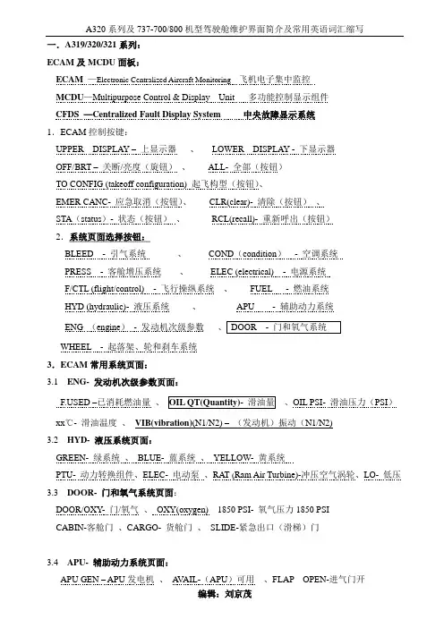
一.A319/320/321系列:ECAM及MCDU面板:ECAM—Electronic Centralized Aircraft Monitoring 飞机电子集中监控MCDU—Multipurpose Control & Display Unit 多功能控制显示组件CFDS —Centralized Fault Display System 中央故障显示系统1.ECAM控制按键:UPPER DISPLAY –上显示器、LOWER DISPLAY - 下显示器OFF/BRT –关断/亮度(旋钮)、ALL- 全部(按钮)TO CONFIG (takeoff configuration) 起飞构型(按钮)、EMER CANC- 应急取消(按钮)、CLR(clear)- 清除(按钮)、STA(status)- 状态(按钮)、RCL(recall)- 重新呼出(按钮)2.系统页面选择按钮:BLEED - 引气系统、COND(condition)- 空调系统PRESS - 客舱增压系统、ELEC (electrical) - 电源系统F/CTL (flight/control) - 飞行操纵系统、FUEL - 燃油系统HYD (hydraulic)- 液压系统、APU - 辅助动力系统ENG (engine)- 发动机次级参数WHEEL - 起落架、轮和刹车系统3.ECAM常用系统页面:3.1 ENG- 发动机次级参数页面:ED –已消耗燃油量、、OIL PSI- 滑油压力(PSI)xx℃- 滑油温度、VIB(vibration)(N1/N2) –(发动机)振动(N1/N2)3.2 HYD- 液压系统页面:GREEN- 绿系统、BLUE- 蓝系统、YELLOW- 黄系统PTU- 动力转换组件、ELEC- 电动泵、RAT (Ram Air Turbine)-冲压空气涡轮、LO- 低压3.3 DOOR- 门和氧气系统页面:DOOR/OXY- 门/氧气、OXY(oxygen) 1850 PSI- 氧气压力1850 PSICABIN-客舱门、CARGO- 货舱门、SLIDE-紧急出口(滑梯)门3.4APU- 辅助动力系统页面:APU GEN – APU发电机、A V AIL-(APU)可用、FLAP OPEN-进气门开EGT(exhaust gas temperature)- 排气温度、LOW OIL LEVEL-低滑油量BLEED xxPSI- APU引气压力、FUEL LO PR (low pressure)- 燃油压力低4–中央故障显示系统(是一个中央维护辅助系统,使维护人员可在驾驶舱提取大部分系统的维护信息,系统故障信息,并对这些系统进行测试。
民航飞机专业术语中英文对照1、the airframe 机身,结构2、The front (fore) part 前部3、The rear (aft) part 后部4、port 左旋(舵)5、starboard 右旋(舵)6、the inboard engine or inboards 内侧发动机7、the outboard engine or outboards 外侧发动机8、the nose 机头9、the belly 腹部10、the skin 蒙皮11、the windscreen or windshield 风挡12、the wing 机翼13、the trailing edge 机翼后缘14、the leading edge 机翼前缘15、the wing tip 翼尖16、the control surface 操纵面17、ailerons 副翼18、flaps (inboard flap,outboard flap,leading edge flaps) 襟翼(内侧襟翼,外侧襟翼,前缘缝翼)19、spoilers (inboard\outboard spoiler)(spoiler down\up)阻力板,扰流板(内、外侧扰流板)(扰流板放下、打开)20、slats 缝翼21、elevators (elevator control tab) 升降舵(升降舵操纵片)22、rudder (rudder control tab) 方向舵(方向舵操纵片)23、flap angle 襟翼角24、flap setting 襟翼调整25、the full flap position 全襟翼位置26、a flapless landing 无襟翼着陆27、the landing gear 起落架28、stabilizer 安定面29、the nose wheel 前轮30、gear locked 起落架锁定31、the wheel well 起落架舱32、the wheel door 起落架舱门33、a tyre 轮胎34、to burst 爆破35、a deflated tyre 放了气的轮胎36、a flat tyre 走了气的轮胎37、a puncture 轮胎被扎破38、to extend the flaps (to retract the flaps) 放下襟翼(收上襟翼)39、gear extention (gear retraction) 起落架放下(起落架收上)40、The gear is jammed. 起落架被卡死。
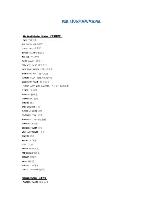
民航飞机各大系统专业词汇Air Conditioning System (空调系统)PACK空调主件HOT BLEED AIR热引气OUTLET DUCT外流管BYPASS VALVE旁通活门RAM AIR 冲压空气INLET SCOOP 进气口TRIM AIR VALVE 调节空气PACK FLOW SWITCH空调主件流量EXTRACTOR FAN 排气风扇GUARDED FLAP 有保护盖的导片ISOLATION VALVE 隔离活门“LIGHT OUT”AUTO POSITION “灯灭”自动状态BLOWER 鼓风机EXTRCTOR排风扇OVERBOARD 机外ONBOARD机上OPEN-CIRCUIT开路CLOSED-CIRCUIT闭路CONFIGURATION 形态PASSENGER LOAD乘客载荷DOWNSTREAM下游STANDING WATER积水ATLN(ALTERNATE)备份CHANNEL通道PNEUMATIC气源DUAL 双的SWITCH OVER交换PRE-COOLER预冷机COOLANT冷却剂AMBER琥珀色VENTILATION通风CIRCUIT BREAKER跳开关PRESSURIZATION (增压)FLAPPER VALVES 瓣状活门TOGGLE 扳钮开关VACUUM 真空ISAO BARIC 等压BAROMETRIC 气压PRESSURE DIFFERENTIALS 压差ANEROID SWITCH 膜盒气压STBY (STANDBY)备份DC DIRECT CURRENCY 直流电PSI (POUND PER SQUARE INCH)磅/平方英尺DITCH 水上迫降SUPERCHARGER 增压器INADVERTENT 偶然的LEAKAGE 漏、渗APRON 停机坪CEILING 顶板FREIGHT 货机ACCESSORY 副件THROTTLE LEVER 油门杆CRUISE 巡航NEGATIVE RELIEF VALVE 负压释放活门POSITIVE PRESSURE 正压AIRPORT ELEVATION 机场标高AUTOPILOT(自动驾驶)MOMENTUM 动量MIMICKING 模仿GLARE-SHIELD 遮光板ACTUATORS 制动器SURVEILLANCE 监视TRAJECTORY 轨迹QUADRANT 油门操纵杆FLEX(FLEXIBLE)灵活的MCT(MAXIMUM CONTINUE THRUST) 最大连续推力 ELEVATORS 升降舵AILERON 副翼NAVAID 助航SID(STANDARD INSTRUMENT DEPARTURE) 标准仪表离场 STAR(STANDARD TERMINAL ARRIVAL ROUTE)标准进场程序 MISSED APPROACH (GO AROUND) 复飞AUGMENTATION 增加、增益FLIGHT ENVELOPE 飞行包线CDU(CONTOL DISPLAY UNIT)控制显示组件FMA(FLIGHT MODE ANNUNCIATOR)飞行方式显示器ADIRS(AIR DATA AND INERTIAL REFERENCE SYSTEM)大气数据及惯性基准系统 MCP(MODE CONTROL PANEL)方式控制面板GPS(GLOBAL POSIITON SYSTEM)全球定位系统FLARE 平飘TOUCHDOWN 接地点FLY-BY-WIRE 电传操纵ACCELEROMETER 加速器ALIGNMENT 对准、校准SERVOMOTOR 伺服马达GYROSCOPE 陀螺THRUST REDUCTION ALT 减推力高度REVERSE 反推ARM 预位FPA(FLIGHT PATH ANGLE)飞行航径角LOCALIZER 航向道IDLE 慢车DETENT 卡位FPV(FLIGHT PATH VECTOR)飞行航径矢量CRM(COCKPIT RESOURCE MANAGEMENT)驾驶舱资源管理PF(PILOT-FLIGHT)把杆飞行员PFD(PRIMARY FLIGHT DISPLAY)主飞行显示PULLEY 滑轮 ROLL 滑跑SCROLL 翻动、卷起SLEW 上下选页VELOCITY 速度DATA BASE LOADER 数据库装载机ALPHA/NUMERIC KEY BOARD 字母/数字键盘SCRATCH PAD 草稿栏DYNAMIC AND BACKGROUD DATA 动态和背景数据TROPOPAUSE 对流层顶CYAN 深蓝色COST INDEX 成本指数ALIGNMENT 校准PROMPT 提示符EFOB(ESTIMATED FUEL ON BOARD) 预计机上燃油MAGENTA 品红色、洋红色EAT(ESTIMATED TIME OF ARRIVING)预计到达时间ADC(AIR DATA COMPUTER)大气数据计算机CRT(CATHODE RAY TUBE)阴极射线管BITE (BUILD-IN TEST EQUIPMENT) 内装测试设备 DEFAULT 缺席LSK(LINE SELECT KAY)行选键ASYMMETRIC 不对称TERMINAL AREA 终端区域COORDINATE 经纬度RNVA AREA NAVIGATION 区域导航EN-ROUTE 在航路上CFDS(CENTRALIZED FAULT DISPLAY SYSTEM)集中显示系统 COMMUNICATION (通讯)VIBRATIONS 振动IMPULSES 脉冲ANTENNA 大线MEGAHERTZ 兆赫兹CURVATURE 弯曲 曲度IONOSPHERE 电离层TRANSCEIVER 无线电收发机RACK 设备架SQUELCH 静噪、噪声控制PASSENGER ADDRESS 旅客广播CABIN INTEROHONE 客舱内话INTERPHONE 内话机EVACUATION 疏散ROTARY 旋转的KNOB 旋钮DEDICATED 专用的BUZZER 蜂鸣声BOOM SET 吊杆耳机HEAD SET 耳机SELCAL 选择呼叫ACTIVE 正在使用HOT MIKEPRESS TO TALK (PTT)按下发话LATCHED 锁住PREEMPT 优先占有STUCK 阻塞PLUG 插入STRAIN 滤网SHIELD 过滤ROCK SWITCH 摇式电门FLIGHT CONTROL SYSTEM(I)(飞行控制(一))REJECTED T/O 中断起飞 CONVENTIONAL 通用的WHEEL 驾驶盘COLUMN 驾驶杆PEDAL 脚蹬SURFACE 舵面RUDDER 方向舵SPEED-BRAKE 减速板FLAP 襟翼STAB TRIM 调整片OVERRIDE SWITCH 超控电门YAW DAMPER 偏航阻尼器 CENTERING MECHANISM 定中机械 SWEEP BACK 后掠SPOILER 扰流板JAM 卡阻ROLL 滚转(横滚)PITCH 俯仰STABILIZER 安定面YAW 偏航YAW DAMPER RATE GYRO 偏航率陀螺仪 LONGITUDINAL AXIS 纵轴VERTICAL AXIS 垂轴LATERAL AXIS 横轴ACTUATING CYLINDER 作动筒 FAIRED POSITION 中立位FALL INTO SPIN 进入螺旋AIRFOIL 翼部面FLIGHT CONTROL SYSTEM(II)(飞行控制(二))SECONDARY FLIGHT CONTROL 辅助飞行操纵HIGH LIFT DEVICE 增升装置TRAILING EDGE(TE)后缘LEADING EDGE(LE)前缘POWER TRANSFER UNIT(PTU)动力传输装置STALL 失速MANEUVER 机动飞行INBOARD 内侧OURBOARD 外侧SLOTTED 开缝的THREE SLOTTED FLAP 三开缝襟翼DRAG 阻力COMPARATOR 比较仪ROLL RATE 滚转率MIXER 混合器DEFLECTION 偏转AERODYNAMIC MEAN CHORD 平均空气动力弦TORQUE 扭力JACK 千斤顶FIRE PROTECTION(I)(防火(一))FIRE PROTECTION 防火OVERHEAT 超温FIRE DETECTION 探火FIRE DETECTION LOOP 探火环FIRE ALERT 火警戒FAULT MONITORING CIRCUIT 失效监控电路WARNING BELL 火警铃GROUND PROXIMITY 近地ENGINE INDICATING AND CREW ALERTING SYSTEM (EICAS)发动机指示和机组警戒系统 CATHODE-RAY-TUBE 阴极射线管ENGINE NACELLE 发动机舱CARGO COMPARTMENT 货舱THERMAL SWITCH 热电门CONTINUOUS-LOOP 连续环路BIMETALLIC 双金属的CERAMIC CORE 陶瓷芯INCONEL TUBE 因康镍合金管CERAMIC BEAD 陶瓷珠EUTECTIC SALT 易熔盐 MALFUNCTION 失效SMOKE DETECTION 烟雾探测SQUIB 爆炸帽IP(INTERMEDIATE PRESSURE)中压 FIRE PROTECTION(II)(防火(二))LOCK DOWN 下锁INADVERTENT 疏忽大意SHUTDOWN 关车UNLOCK 开锁TRIP 跳开关THRUST REVERSER 反推INERT COLD GAS AGENTS 惰冷气灭火剂 OXIDIZER 氧化剂CARBON DIOXIDE(CO2)二氧化碳 NITROGEN(N1)氮INERT GAS 惰气TOXICITY 毒性FREON 氟利昂SOLVENT 溶剂COMPATIBLE 与……相溶 CARTRIDGE 燃爆筒LAGGING 绝缘材料SOAK 浸、泡RESIDUE 滤渣、残余物 EXTINGUISHING AGENT 灭火剂 PRESSURE GAUGE 压力表MANIFOLD 管道RUPTURE 破裂UPHOLSTERY 饰面材料NOXIOUS GAS 毒气ELECTRICAL SYSTEM(I)(电子系统(一))GENERATE 发电DISTRIBUTE 配电ESSENTIAL POWER 重要设备电源VOLTAGE 电压PHASE 相TRANSFORMER RECTIFIER UNIT(TRU)变压整流器BUS 汇流条LIGHTING CIRCUIT 照明电路EMERGENCY POWER 应急电源STANDBY POWER 备用电源ONBOARD 机载STATIC INVERTER 静变流机BATTERY 电瓶RAM AIR-DRIVER GENERATOR 冲压空气驱动发电机NICKEL CADMIUM BATTERY 镍镉电池CONSTANT SPEED DRIVE(CSD)恒速驱动FREQUENCY 电频INTEGRATED DRIVE GENERATOR(IDG)综合驱动发电机ENGINE-DRIVEN GENERATOR 发动机驱动的发电机BATTERY CHARGER 电瓶充电器SWITCHED HOT BATTERY BUS 转换热电瓶汇流条ELECTRICAL LOAD 电载荷ELECTRICAL SYSTEM(II)(电子系统(二))TRANSFER BUS 转换汇流条TRANSFER RELAY 转换继电器RESPECTIVE 各自的MOMENTARILY 瞬间的ONSIDE 本侧LOAD 载荷、电荷TRIP OFF 跳开CHARGE 充电SERVICE BUS 勤务汇流条SPLIT BUS 分裂汇流条BUS TIE BREAKER (BTB)汇流条连接断路器GENERATOR CONTROL UNIT(GCU)发动机控制组件MONITOR 监控DIVISION 分配DIFFERENTIAL PROTECTION CURRENT TRANSFORMERS(DPCTs)压差保护电流变压器 OPEN 断开SHORT 短路SYNCHRONOUS BUS 同步汇流条FUEL(燃油)INNER FUEL TANK 内侧燃油箱INTEGRAL TANK 整体油箱WING/FUSELAGE STRUCTURE 机翼/机身结构WING TIP 翼尖FUEL NOZZLE 燃油喷嘴CIRCULATE 循环VENT SURGE TANK 通风(防震动)油箱SPILLAGE 溢出CROSS-LINE 横条线DIVERT 转向GROSS WEIGHT (GW)全重REFUEL ACCESS DOOR 加油板的盖板REFUEL COUPLING DOOR 加油口盖SHROUD DRAIN MAST 排放管罩E/WD ENGINE AND WARNING DISPLAY 发动机警告指示 SPOUT 喷射INJECT 喷射CROSS FEED VALVE 交输供油活门SUCTION VALVE 虹吸活门CONDENSATION OF MOISTURE 水气凝结SEDIMENT 沉积物RUPTURE 破裂OVERFLOW DRAIN 溢流口REPLENISH 加油REFUEL PANEL ACCESS DOOR 加油面板盖板SINGLE REFILLING POINT 单点加油口REFUEL COUPLING DOOR 加油连接口盖SURGE TANK 通风油箱MAGNETIC FUEL LEVEL INDICATOR 磁性油尺FLUSH 齐平DRAIN VALVE 排放活门、排水活门 MAINTENANCE 维护、维修FLOAT VALVE 浮子活门FILLER CAP 漏斗口DUMP/JETTISON 放油HYDRAULIC SYSTEM (液压系统)RESERVOIR 液压油箱、水库FILTER 滤器、滤纸ACCUMULATOR 储压器、储蓄器EXPEL 排出、赶出PISTON 活塞CHARGE 释放、放出WHEEL BRAKE 机轮刹车装置NOSE WHEEL STEERING 前轮转向操纵PRIMARY FLIGHT CONTROL SURFACE 主飞行操纵面 PRESSURE REGULATOR 调压器EMERGENCY PUMP 应急泵CHECK VALVE 单向活门SELECTOR VALVE 选择活门ACTUATING VALVE 卸荷活门 PREDETERMINED VALVE 预定值BALL VALVE 球形活门RETURN LINE 回油管路SPRING PRESSURE 弹簧压力STANDPIPE 竖管ICE AND RAIN (冰和雨)REPELLENT 防护剂SPRAY 喷、向……喷射PERFORATE 穿孔于THERMAL ANTI-ICING SYSTEM 热防冰系统 POTABLE WATER LINES 饮用水线WINDSHIELD 风挡ENGINE COWL 发动机整流罩WIPER 刮水器STATIC PORT 静压口AOA(THE ANGLE OF ATTTACK)迎角TAT(TOTAL AIR TEMPERATURE)全温SAT(STATIC AIR TEMPERATURE)静温VINYL CORE 乙烯树脂内芯GLASS PANE 玻璃窗格BIRD-STRIKE 鸟击CONDUCTIVE COATING 导电涂层ACRYLIC PANE 丙烯酸树脂ANGLE AIRFLOW SENSOR 气流角度传感器DALAY CIRCUIT 延迟电路SOLENOID VALVE 电磁活门SIGHR GAGE 目视测量表EIS(电子仪表系统)ATTENTION GATTER 提醒灯CHRONOGRAPH 记时器ELAPSED TIME 已飞时间PARAMETER 参数CHECKLIST 检查单DISPENSE WITH 省略UN-CLUTTER 混乱UTC(COORDINATED UNIVERSAL TIME)协调世界时 SCHEMATIC 图解形式EADI 电子姿态指示器EHSI 水平状态指示器SYMBOL GENEERATOR 符号发生器ARC MODE 弧型模式ROSE MODE 罗盘模式BEARING POINTER 方位指针DECISION HEIGHT 决断高度ADF(AUTOMATIC DIRECTION FINDER) 自动定向机GLIDE-SLOPE 下滑道DEVIATION 偏差SIDE SLIP 侧滑INTERFACE 界面、接口、连接ANALOG 模拟DFDR(DIGITAL FLIGHT DATA RECORDER)数字式飞行数据记录器 AN UNDERWATER LOCATOR BEACON 水下信标机DISCRETE SIGNAL 离散信号SLIP BALL 球形侧滑仪CROSS BAR 十字指令杆STOP-WATCH WAY 秒表(跑表)记时方式ROLL INDEX 横滚标志SUPERIMPOSE 重叠REFERENCE LINE 参考线SPEED TREND ARROW 速度趋势箭头TRUE NORTH 真北RAW DATA 原始数据LUBBER LINE 航向标线DEVIATION BAR 偏离杆COURSE POINTER 航道指针GRADUATION 刻度REMOTE 分装A DOUBLE LINED ARROW 双线箭头指针(双针)A GRAY ANALOG ALTITUDE TAPE 灰色模拟高度标尺带FRONT COOURSE DAGGER 向台航道箭形符号AIDS 飞机集成数据系统ECAM(ELECTRONIC CENTRALIZED AIRCRAFT MONITOR )电子飞机集中监控SYNOPISIS 概要ORIENTATION 定向INDENT 缩进DISCRATE INPUT SIGNALS 离散的输入信号MINIMUM EQUIPMENT LIST(MEL)最低设备清单LANDING GEAR(起落架)GROUND LOOP 打地转NOSE OVER 拿大顶MARGIN 斜度CHOCK 轮挡BUNGEE CORD 弹簧索(减震支柱)ALUMINUM ALLOYS 铝合金SHOCK ABSORBER 减震器、缓冲器RUBBER BLOCK 橡皮块(减震器)OIL-AIR STRUT 油气式减震支柱TAILWHEEL GEAR 后三点式起落架TRICYCLE GEAR 前三点式起落架ANTISKID 防滑装置SHOCK STRUT 减震支柱UPLOCK HOOK 上位锁钩(起落架的)ALTERNATE EXTENSION (起落架)备用放出ACTUATOR 致动器、动作筒PSEU(PROXIMITY SWITCH ELECTRONIC UNIT)接近电门电子组件 TORSION LINKS 扭力臂TRUCK ASSEMBLY 轮架组件TRUNNION LINK 轴颈连杆TILLER 操纵杆NOSEWHEEL STEERING 前轮转向操纵THRUST REVERSER 反推装置SHUTTLE VALVE 往复活门DOWN-LOCK LINK 下锁连杆TILT 倾斜CENTERING CAM 定中凸轮OVER-CENTERING 过中BEARING 轴承CARBON BRAKE 碳素钢刹车NAVIGATION(I)导航(一)DEW POINT 露点NOISE ABATEMENT 减噪VOR(VERY-HIGH-FREGUENCY OMINI-DIRECTIONAL RANGE)甚高频全向信标VOR ORIENTATION VOR 定向、定位AIR DATA INERTIAL REFERENCE UNITS(ADIRU)大气数据惯性基准组件DIGITAL DISTANCE AND RADIO MAGNETIC INDICATOR (DDRMI)数字距离无线电磁指示器 GPWS(GROUND PROXIMITY WARNING SYSTEM) 近地警告系统THRESHOLD 跑道入口ADF(AUTOMATIC DIRECTION FINDER)自动定向仪DME(DISTANCE MEASURING EQUIPMENT)测距仪PILOYAGE 地标领航AGL(ABOVE GROUND LEVEL)离地高度PFV(FLIGHT PATH VECTOR)飞行航经引导LASER GYRO 激光陀螺BEACON 信标台NAVIGATION(II)导航(二)TCAS(TRAFFIC AND COLLISION AVOIDANCE SYSTEM)空中交通避撞系统CAGING KNOB 锁定旋钮NEAR MISS 危险接近ATA(AIR TRANSPORT ASSOCIATION OF AMERICA)美国航空协会THRESHOLD 入口、标准APU(AUXILIARY POWER UNIT)(辅助动力装置)GAUGE 表CIRCUIT 电路、一圈DISCHARGE 放电SHUTDOWN 关车MAINTENANCE 维护、维修OVER-SPEED 超速LOAD 负荷ACCESS DOOR 进口门TUCK 使……隐藏PLENUM 集气室INDUCTION SYSTEM 进气系统INCIPIENT 早期的VARIABLE INLET GUIDE VANES 可调的进气导片 NOMINAL 额定的JEPPESEN CHARTS(杰普逊航图)INSTRUMENT FLIGHT 仪表飞行PHASE 阶段DEPARTURE 离场ENROUTE 航路ARRICAL 进场TRANSITION 过渡PROCEDURE 程序INSTRUMENT APPROACH 仪表进近SID(STANDARD INSTRUMENT DEPARTURE)标准仪表离场 STAR(STANDARD TERMINAL ARRIVAL ROUTE)标准进场航路 CHART LAYOUT 航图布局SYMBOLOGY 符号FACILITY 设施COMMUNICATION FREQUENCY 通信频率MSA(MINIMUM SAFE ALTITUDE)最低安全高度PLAN VIEW 平面图NAVIAID 导航、助航MORSE CODE 莫尔斯代码PROCEDURE TURN 程序转弯OUTBOUND 背台HOLDING 等待HEADING 航向RADIAL 径向线MISSED APPROACH 复飞MOCA 最低超障高度MAP 复飞点MSA 最低安全高度LDA 可用着陆距离MLS 微波着陆系统SDF 简易定向设施PAR 初始进近雷达MSL 平均海平面TEARDROP PATTERN 修正角HAT 高出接地点的高HAA 高出机场的高MEA 最小航路高RVR 跑道视程CLIMB (爬升)ROTATE 抬轮STICK SHAKER 抖杆BUFFET 发动机抖震OVERSHOOT 目测过高FUEL PRUDENT 节油OROGRAPHIC TURBULENCE 山岳形态的气流 PENALTY DRAG 阻力增大CB ACTIVITYDRAG 积云CONCEDE A REROUTE A提供一条新航路 OPTIMUM ALTITUDE 最适高度。
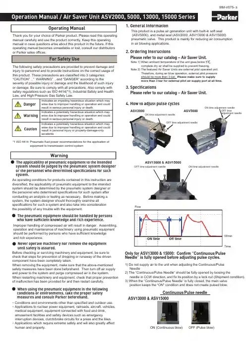
WarningThe applicability of pneumatic equipment to the intended system should be judged by the pneumatic system designer or the personnel who determined specifications for such system.1. General InformationThis product is a pulse air generation unit with built-in soft seal (ASV5000), and metal seal (ASV2000, ASV13000 & ASV15000) pneumatic valve. This product is mainly for reducing air consumption in air blowing applications.2. Ordering InstructionsPlease refer to our catalog – Air Saver Unit.Note 1) When ambient temperature of the unit goes below 5 , complete dry air shall be supplied to prevent freezing.Note 2) The featured Air Saver Units are external pilot operated unit. Therefore, during air blow operation, external pilot pressure should be more than 3 bar. Please make sure to supplymore than 3 bar for external pilot air supply port at all time.3. SpecificationsAs operating conditions for products contained in this instruction are diversified, the applicability of pneumatic equipment to the intended system should be determined by the pneumatic system designer or the personnel who determined specifications for such system after conducting an analysis or testing as necessary. Before making a system, the system designer should thoroughly examine allspecifications for such a system and also take into consideration the possibility of any trouble with the equipment.The pneumatic equipment should be handled by persons who have sufficient knowledge and rich experience.Never operate machinery nor remove the equipment until safety is assured.Before checking or servicing machinery and equipment, be sure to check that steps for prevention of dropping or runaway of the driven component have been completely taken.When removing the equipment, make sure that the above-mentioned safety measures have been done beforehand. Then turn off air supply and power to the system and purge compressed air in the system.When restarting machinery and equipment, check that proper prevention of malfunction has been provided for and then restart carefully.When using the pneumatic equipment in the following conditions or environments, take the proper safety measures and consult Parker beforehand.Conditions and environments other than specified and outdoor use. Applications to nuclear power equipment, railroads, aircraft, vehicles, medical equipment, equipment connected with food and drink, amusement facilities and safety devices such as emergencyinterruption devices, clutch/brake circuits for a press and the likes. Applications which require extreme safety and will also greatly affect human and property.Improper handling of compressed air will result in danger. Assembling, operation and maintenance of machinery using pneumatic equipment should be performed by persons who have sufficient knowledge and rich experience.Please refer to our catalog – Air Saver Unit.4. How to adjust pulse cyclesASV2000ASV5000ON time adjustment needleOFF time adjustment needleON time adjustment needleOFF timeadjustment needleON time adjustment needleOFF time adjustment needleASV13000 & ASV15000TimeƐ PLQ FlowON time Off timeOnly for ASV13000 & 15000: Confirm “Continuous/Pulse Needle” is fully opened before adjusting pulse cycles.1) Do not supply air to the unit when adjusting the Continuous/Pulse Needle2) The “Continuous/Pulse Needle” should be fully opened by loosing theneedle in CCW direction, and fix its position by a lock nut (Shipment condition). 3) When the “Continuous/Pulse Needle” is fully closed, the main valve position keeps the “ON” condition and does not create pulsed blow.Continuous/Pulse needleASV13000 & ASV15000ON (Continuous blow)OFF (Pulse blow)Operating ManualIndicates an impeding hazardous situation which may arise due to improper handling or operation and could result in serious personal injury or death.Danger WarningCautionIndicates a potentially hazardous situation which may arise due to improper handling or operation and could result in serious personal injury or death.Indicates a potentially hazardous situation which may arise due to improper handling or operation and could result in personal injury or property-damage-only accidents.!!!Thank you for your choice of Parker product. Please read this operating manual carefully and use the product correctly. Keep this operating manual in case questions arise about this product in the future. If this operating manual becomes unreadable or lost, consult our distributors or Parker sales offices.*1 ISO 4414: Pneumatic fluid power recommendations for the application of equipment to transmission control systemFor Safety UseThe following safety precautions are provided to prevent damage and injury to personnel and to provide instructions on the correct usage of this product. These precautions are classified into 3 categories: “CAUTION”, ”WARNING”, and “DANGER” according to theseverity of possible injury or damage and the likelihood of such injury or damage. Be sure to comply with all precautions. Also comply with safety regulations such as ISO 4414(*1), Industrial Safety and Health Law, and High Pressure Gas Safety Law.9IM-V075-*Adjust frequency of pulsed air to less than5Hz (ASV2000&ASV5000),0.1~1Hz (ASV13000&15000). If frequency of pulsed air is higher than 5 Hz, (ASV2000&ASV5000),1Hz (ASV13000&ASV15000), operation of the pneumatic circuit (logistic element) may become unstable.CautionWhen air blow is not desired, be sure to cut air supply to the Air Saver Unit. Air blow may come out even the ON/OFF time adjustment needles are fully tightened. This unit is not designed to be an “OFF” valve.5. Notes for usageA)Before pipingThoroughly flush the inside of any pipes to remove chips, coolant, dust and etc. B) Air quality$LU 6DYHU UHTXLUHV DQ DLU ILOWHU ZLWK ILOWUDWLRQ RI ȝP RU ILQHU2) If it is difficult to make filter drain management periodically, Parker recommends setting up an air filter with automatic drain mechanism. 3) Be sure to take proper maintenance for a compressor. If sludgeproduced in compressor oil enters pneumatic equipment, it will cause operation failure of pneumatic equipment. Parker recommends setting up a coalescing filter after a filter.C) Pneumatic circuitThis unit is external pilot operated valve. To avoid malfunctions due to pressure drops, the external pilpt air supply pressure must be more than 3 bar at all times. To avoid pressure drops during air blowing process, set up relatively higher supply pressure and use tubes with proper diameter.D) Stopping the air blowBe sure to cut air supply to Air Saver Unit when air blow is not used. Blown air may come out even if the ON/OFF time adjustment needles are fully tightened.E) LubricationThis product does not require lubricated air. Please do not lubricate it.6. Failure and trouble shootinga) Failure and countermeasureFailure condition CauseCountermeasureThe unit cannot be operated.Operating frequency is getting slower.Supply air might be less than 3 bar during operation.Adjust supply air pressure properly.Substantial air leakage is observed.From mainvalve part From basegasketValve part is contaminated with dust or sludge.Dust or high viscosity oil is trapped in the valve and it obstructs the spool.Contaminant is caught inside of the pneumatic circuit, and it blocks up the flow.Contaminant accumulatedin the exhaust port,obstructing the air flow.Spool seal rings are damaged.Tightening torque for mounting screws is not enough to mount valve.1)Replace the product.2)If an air filter is notused, use an air filter.3)If problem is sludge,use a coalescing filter.1)Replace the product.2)If air filter is not used, use an air filter.Replace the logic element.Clean air mufflers orreplace them.Replace the master valve.Tighten mounting screws to appropriate torque.7. Maintenance and disassemblyRegarding repair and maintenance, please consult Parker.As a general rule, do not attempt maintenance or disassemble.If it is absolutely necessary to do maintenance work, keep the following points in mind.1) Make sure that the actuators such as cylinders will not cause damage if they move.2) Cut off electricity.3) Cut off pneumatic pressure and exhaust air in the line.4) Clean up the surroundings of the valve.CautionPreparation for air supply and adjustment of pulse time1) After piping to Air Saver Unit and while the supply air is shut off, fully close the ON time adjustment needle (clockwise rotation) and fully loosen the OFF time adjustment needle (counter clockwise rotation).There are dots on the screw heads of adjustment needles. Please use the dots for position indication of ON/OFF adjustment.2) Turn on air to the supply port, air should pass to the output port continuously.3) Slowly loosen the ON time adjustment needle in CCW direction. A pulsed air blow with short OFF time will start. It is suggested to stop rotating the ON time adjustment needle at around 3 turns (for ASV2000), 2 turns (for ASV5000), or 1.5 turns (for ASV13000&15000) in CCW direction.4) ASV2000&ASV5000:Next, adjust the OFF time by slowly tightening the OFF time adjustment needle in CW direction. The OFF time of the pulsed air blow will get longer. Stop rotating the OFF time adjustment needle at around 7 turns (for ASV2000) or 5 turns (for ASV5000). This should result in about 50% ON/OFF duty of pulsed air blow at 1.5Hz (ASV2000) or 2Hz(ASV5000). ASV13000&15000:Close OFF time adjustment needle fully by screwing the needle in CW direction. Then, slowly loosen about 2 turns in CCW direction. This should result in about 1Hz and 50% duty pulsed air blow.5) Use the procedure of 4) as a starting point, and make the frequency and duty adjustments required in your application by using the ON time and OFF time adjustment needles.6) Fix the adjustment position by tightening lock nuts on adjustment screws.NoteAny request of after-service or maintenance parts, please contact our distributors or Parker customer service. Keep this operation manual. This operation manual would be changed without notice. Please check the newest version.Any attempt to repair and/or disassembling of the product by the user violates the warranty and Parker does not take any responsibility for damage and injury caused by it.Kuroda Pneumatics Ltd(Parker Hannifin Automation Division Japan)10243 Kamakazu, Asahi city, Chiba 289-2505, Japan。
民航飞机专业术语中英文对照1、the airframe 机身,结构2、The front (fore) part 前部3、The rear (aft) part 后部4、port 左旋(舵)5、starboard 右旋(舵)6、the inboard engine or inboards 内侧发动机7、the outboard engine or outboards 外侧发动机8、the nose 机头9、the belly 腹部10、the skin 蒙皮11、the windscreen or windshield 风挡12、the wing 机翼13、the trailing edge 机翼后缘14、the leading edge 机翼前缘15、the wing tip 翼尖16、the control surface 操纵面17、ailerons 副翼18、flaps (inboard flap,outboard flap,leading edge flaps) 襟翼(内侧襟翼,外侧襟翼,前缘缝翼)19、spoilers (inboard\outboard spoiler)(spoiler down\up) 阻力板,扰流板(内、外侧扰流板)(扰流板放下、打开)20、slats 缝翼21、elevators (elevator control tab) 升降舵(升降舵操纵片)22、rudder (rudder control tab) 方向舵(方向舵操纵片)23、flap angle 襟翼角24、flap setting 襟翼调整25、the full flap position 全襟翼位置26、a flapless landing 无襟翼着陆27、the landing gear 起落架28、stabilizer 安定面29、the nose wheel 前轮30、gear locked 起落架锁定31、the wheel well 起落架舱32、the wheel door 起落架舱门33、a tyre 轮胎34、to burst 爆破35、a deflated tyre 放了气的轮胎36、a flat tyre 走了气的轮胎37、a puncture 轮胎被扎破38、to extend the flaps (to retract the flaps) 放下襟翼(收上襟翼)39、gear extention (gear retraction) 起落架放下(起落架收上)40、The gear is jammed. 起落架被卡死。


1、the airframe 机身,结构2、The front (fore) part 前部3、The rear (aft) part 后部4、port 左旋(舵)5、starboard 右旋(舵)6、the inboard engine or inboards 侧发动机7、the outboard engine or outboards 外侧发动机8、the nose 机头9、the belly 腹部10、the skin 蒙皮11、the windscreen or windshield 风挡12、the wing 机翼13、the trailing edge 机翼后缘14、the leading edge 机翼前缘15、the wing tip 翼尖16、the control surface 操纵面17、ailerons 副翼18、flaps (inboard flap,outboard flap,leading edge flaps) 襟翼(侧襟翼,外侧襟翼,前缘缝翼)19、spoilers (inboardoutboard spoiler)(spoiler downup) 阻力板,扰流板(、外侧扰流板)(扰流板放下、打开)20、slats 缝翼21、elevators (elevator control tab) 升降舵(升降舵操纵片)22、rudder (rudder control tab) 向舵(向舵操纵片)23、flap angle 襟翼角24、flap setting 襟翼调整25、the full flap position 全襟翼位置26、a flapless landing 无襟翼着陆27、the landing gear 起落架28、stabilizer 安定面29、the nose wheel 前轮30、gear locked 起落架锁定31、the wheel well 起落架舱32、the wheel door 起落架舱门33、a tyre 轮胎34、to burst 爆破35、a deflated tyre 放了气的轮胎36、a flat tyre 走了气的轮胎37、a puncture 轮胎被扎破38、to extend the flaps (to retract the flaps) 放下襟翼(收上襟翼)39、gear extention (gear retraction) 起落架放下(起落架收上)40、The gear is jammed. 起落架被卡死。
1.A spoiler is a device intended to reduce lift in an aircraft. Spoilers are plates on the top surface of a wing which can be extended upward into the airflow and spoil it. Flaps are hinged surfaces on the trailing edge of the wings. As flaps are extended, the stalling speed of the aircraft is reduced, which means that the aircraft can fly safely at lower speeds (during takeoff and landing). Slats are on the leading edge of the wings which, when deployed, allow the wing to operate at a higher angle of attack. They are intended to reduce the stalling speed by altering the airflow over the wing.1.扰流板是用来降低飞机升力的装置。
扰流板是机翼上表面的板,它可以向上延伸到气流中,从而扰乱气流。
襟翼是机翼后缘铰接的表面,随着襟翼的伸展,飞机的失速速度降低,这意味着飞机(在起飞和降落期间)可以以较低的速度安全飞行。
翼板位于机翼的前缘,当展开时,可以使机翼以更高的攻角运行。
它们的目的是通过改变机翼上的气流来降低失速速度。
2.The largest aircraft to be built, is the Antonov An-225. This aircraft comes from the Ukraine, and it was built back in the 1980s. This aircraft includes 6 engines, mounted on the wing. Its wingspan is 88 meters (289 feet) and it is 84 meters long (276 feet). This aircraft holds the world payload record, after it transported 428,834 pounds worth of goods. Weighing in at 1.4 million pounds, it is also the heaviest aircraft to be built.2.将要建造的最大的飞机是安东诺夫An-225。
Manual / Air Saver Unit -ASV2000, 5000, 13000, 15000 Series9IM-E075-bEdition : March 2017ManualThank you for your choice of Parker product. Please read this operating manual carefully and use the product correctly. Keep this operating manual in case questions about this product arise in future. If this operating manual becomes unreadable or lost, consult our distributors or Parker sales offices.Safety instructionsThe following safety precautions are provided to prevent personal injury and damage to property and to provide instructions on the correctusage of this product. These precautions are classified into 3 categories: “CAUTION” , ” WARNING” , and “DANGER” according to the severity of possible injury or damage and the likelihood of such injury or damage.Be sure to comply with all precautions. Also comply with safety regulations such as ISO 4414(*1), Industrial Safety and Health Law, and High Pressure Gas Safety Law.*1 ISO 4414: Guidelines and pneumatic fluid power recommendations for pneumatic systems and their components.WarningAttention• This product is designed for pneumatic devices.The applicability of pneumatic equipment to the intended system should be judged by the pneumatic system designer or the personnel who determined specifications for such system.• Since the operating conditionsfor the products contained in this instruction are diversified, the applicability of pneumatic equipment to the intended system should be determined by the pneumatic system designer or the personnel who determined specifications for such system. Before making a system, the system designer should thoroughly examine all specifications for such a system and also take into consideration the possibility of anytrouble with the equipment.• The pneumatic equipment should only be handled bypersons who have sufficient knowledge and rich experienceImproper handling of compressed air will result in danger. Assembling,operation and maintenance of machinery using pneumatic equipment should be performed by persons who have sufficient knowledge and rich experience.• Never operate machinery nor remove the equipmentuntil safety is assured.Before checking or servicing machinery and equipment, be sure to check that steps for prevention of dropping or runaway of the driven component have been completely taken.When removing the equipment, make sure that the above-mentioned safety measures have been done beforehand.Then turn off air supply and power to the system and purge compressed air in the system.When restarting machinery and equipment, check that proper preventionof malfunction has been provided for and then restart carefully.• When using the pneumatic equipment in the followingconditions or environments,take the proper safety measures and consult Parker before hand.• Conditions and environments (other than specified) andoutdoor use.Applications to nuclear power equipment, railroads, aircraft, vehicles, medical equipment, equipment connected with food and drink, amusement facilities and safety devices such as emergencyinterruption devices, clutch/brake circuits for a press and the likes.Applications which require extreme safety and will also greatly affecthuman and property.1) After piping to Air Saver Unit and while the supply air is shut off, fully close the ON time adjustment needle (clockwise rotation) and fully loosen the OFF time adjustment needle (counter clockwise rotation). Please use the dots for position indication of ON/OFF adjustment.2) Turn on air to the supply port, air should pass to the output port continuously.3) Slowly loosen the ON time adjustment needle in CCW direction. A pulsed air blow with short OFF time will start. It is suggested to stop rotating the ON time adjustment needle at around 3 turns (for ASV2000), 2 turns (for ASV5000), or 1.5 turns (for ASV13000&15000) in CCW direction.4) ASV2000&ASV5000: Next, adjust the OFF time by slowly tightening the OFF time adjustment needle in CW direction.The OFF time of the pulsed air blow will get longer.It is suggested to stop rotating the OFF time adjustment needle at around 7 turns (for ASV2000 or 5 turns (for ASV5000). This should result in about 50%ON/OFF duty of pulsed air blow at 1.5Hz (ASV2000) or 2Hz(ASV5000).ASV13000&15000:Close OFF time adjustment needle fully by screwing the needle in CW direction. Then, slowly loosen about 2 turns in CCW direction. This should result in about 1Hz and 50% duty pulsed air blow.5) Use the procedure of 4) as a starting point, and make the frequency and duty adjustments required in your application by using the ON time and OFF time adjustment needles.6) Fix the adjustment position by tightening lock nuts on adjustmentscrews.Regarding repair and maintenance, please consult Parker.* Adjust frequency of pulsed air to less than 5Hz (ASV2000&ASV5000), 0.1~1Hz (ASV13000&15000). If frequency of pulsed air is higher than 5 Hz (ASV2000&ASV5000), 1Hz (ASV13000&ASV15000),operation of the pneumatic circuit (logistic element) may become unstable.• Be sure to cut air supply to Air Saver Unit when air blow is not used.Blown air may come out even if the ON/OFF time adjustment needles are fully tightened.This unit is not designed to be an “OFF” valve.Pin adjustment for continuous / pulse operation. ASV13000 & ASV150006.Notes for intended use 5.AttentionMaintenance and dismantling7.1.2.3.For more information, see Air Saver catalog.4.ASV2000ASV5000ASV13000 & ASV15000Adjustment needle for setting the switch-on time OFFONON timeadjustment needleOFF timeadjustment needleOFF timeON timeadjustment needleF l o wON time OFF timeTimeOnly for ASV13000 & 15000: Confirm “Continuous/Pulse Needle” is fully opened before adjusting pulse cycles.1) Do not supply air to the unit when adjusting the Continuous/Pulse needle2) The “Continuous/Pulse Needle” should be fully opened by loosing the needle in CCW direction, and fix its position by a lock nut (Shipment condition).3) When the “Continuous/Pulse Needle” is fully closed, the main valve position keeps the “ON” condition and does not create pulsed blowOFF (air is blown continuously )ON (pulse blow)a) Failure and countermeasureFailure conditionCauseCountermeasure The unit cannot be operated.Pilot supply air might be less than 3 bar during operation.Adjust pilot supply air pressure properly.Valve part is contaminatedwith dust or sludge.1)Replace the product. 2)If air filter is not used, use an air filter.3)If problem is sludge, use a coalescing filter.Operating frequency is getting slower.Dust or high viscosity oil is trapped in the valve and it obstructs the spool.1)Replace the product. 2)If air filter is not used, use an air filterContaminant is caught inside of the pneumatic circuit, and it blocks up the flowReplace the logic element.Contaminant accumulated in the exhaust port,obstructing the air flow.Clean air mufflers or replace them.From main substantial air valve part leakage is observedFrom base gasket spool seal rings are damaged.Replace Air Saver Unit.From base gaslet spool seal rings are damaged.Tightening torque for mounting screws is not enough to mount valve.Tighten mounting screws to appropriate torque.A) Before commissioning of pipingThoroughly flush the inside of any pipes to remove chips, coolant, dust, etc.B) Air quality2) If it is difficult to make filter drain management periodically, Parker recommends setting up an air filter with automatic drain mechanism. 3) Be sure to take proper maintenance for a compressor. If sludge produced in compressor oil enters pneumatic equipment, it will cause operation failure of pneumatic equipment.Parker recommends setting up a coalescing filter after a filter.C) Pneumatic circuitThis unit is an external pilot operated valve. To avoid malfunctions due to pressure drops, the external pil0t air supply pressure must be more than 3 bar at all times. To avoid pressure drops during air blowing process, set up relatively higher supply pressure and use tubes with proper diameter.D) Stopping the air blowBe sure to cut air supply to Air Saver Unit when air blow is not used.Blown air may come out even if the ON/OFF time adjustment needles are fully tightened.E) LubricationThis product does not require lubricated air. Please do not lubricate it.As a general rule, do not attempt maintenance or disassemble.If it is absolutely necessary to do maintenance work, keep the following points in mind.1) Make sure that the actuators such as cylinders will not cause damage if they move.2) Cut off electricity.3) Cut off pneumatic pressure and exhaust air in the line. 4) Clean up the surroundings of the valve.• Any attempt to repair and/or disassembling of the product by the userviolates the warranty.Parker does not take any responsibility for damage and injury caused by it.NoteAny request of after-service or maintenance parts, please contact our distributors or Parker customer service. Keep this operation manual. This operation manual would be changed without notice.Please check the newest version.Regarding repair and maintenance, please consult Parker.This product is a pulse air generation unit with built-in soft seal (ASV5000), and metal seal pneumatic valve (ASV2000, ASV13000 & ASV15000). This product is mainly for reducing air consumption in air blowing applications.Note 1) When ambient temperature of the unit goes below 5° C,Complete dry air shall be supplied to prevent freezing.Note 2) The featured Air Saver Units are external pilot operated unit. Therefore, during air blow operation, external pilot pressure should be more than 3 bar.Please make sure to supply more than 3 bar forexternal pilot air port at all time.Please refer to our catalogue – Air Saver Unit.Port A - 3/8 pluggedPort B - 3/8Pilot air supply port M5Port R2 - 3/8 pluggedOFF time adjustment needle Threshold elementNote: Be careful about mounting direction3 x Ø7(Mounting hole)2525530304881155468182PipingPort 1: Supply port (Compressor side)Port 2: Supply port Port 3: Supply portPort 4: Output port (Blow nozzle side) Port 5: Supply port Air supply(Note: the air pressure should be more than 3 bar.)To use the connection as normally open, please proceed as follows Port 1: Supply port (Compressor side)Port 2: Output port (Blow nozzle side)Port 3: Supply port Port 4: Supply port Port 5: Supply port Air supply(WP)ASV2000-AA-XXPipingPort 1: Supply port (Compressor side) Port 2: Supply port Port 3: Supply portPort 4: Output port (Blow nozzle side) Port 5: Supply port Air Supply(Note: the air pressure should be more than 3 bar.)To use the connection as normally open, please proceed as follows.Port 1: Supply port (Compressor side)Port 2: Output port (Blow nozzle side)Port 3: Supply port Port 4: Supply port Port 5: Supply port Air supplyPort X - M5 - Pilot Air Supply portThreshold elementPlug2 x Ø5.5(mounting hole)306,5605038,55017161622,590,5Max 15,529,515,515,5Port 4 - 1/2Port 1 - 1/232324692OFF timeadjustment needlePort 3 , 5 - 3/8 pluggedPlugPort 2PlugON timeadjustment needle(WP)ASV5000-AA-XXON time adjustment needleMax 15,5Port R1 - 3/8 pluggedPort 1 - 3/864,5302015Kuroda Pneumatics Ltd(Parker Hannifin Automation Division Japan)10243 Kamakazu,Asahi ort,Chiba 289-2505,Japan 91M-V075-b - V1 - March 2017© 2017 Parker Hannifin Corporation. All rights reserved.(WP)ASV15000-AA-XXPipingPort 1: Supply port (Compressor side) Port 2: Supply port Port 3: Supply portPort 4: Output port (Blow nozzle side)Port 5: Supply port Air Supply(Note: the air pressure should be more than 3 bar.)To use the connection as normally open,please proceed as follows.Port 1: Supply port (Compressor side)Port 2: Output port (Blow nozzle side)Port 3: Supply port Port 4: Supply port Port 5: Supply port Air supplyONPilot air port 1/8 BSPPOFF timeadjustment needle ON time adjustment needle4 x Ø11(Mounting hole)1A398771122OFF 5941,594,59131118100172106859518202029,5Port 1, 2, 3 (3x 1 BSPP)149AONPort 4 -1.1/4 BSPPOFF timeadjustment needleON timeadjustment needle 4 x Ø11(Mounting hole)Port 1 -1.1/4 BSPP2058204OFF 10799144302511586193144168Pilot Air supply 1/8 BSPP7558Port 2Plug2282929Port 3PlugPort 5Plug (WP)ASV13000-AA-XX。
FIELD DEVICES – CONTROLLERSProduct Specifications43AP Pneumatic Indicating ControllersThese instruments indicate and control pressure, temperature, vacuum, and differential pressure. They provide process industries with a highly dependable and versatile group of instruments.WIDE SELECTION OF MEASURING ELEMENTS Foxboro products offer the widest variety of element constructions and ranges in the industry. This versatility enables the 43AP Series Pneumatic Indicating Controllers to be applied to virtually any process.WIDE CHOICE OF CONTROL MODESOn-off, proportional, proportional plus derivative, proportional plus integral (reset), proportional plus integral plus derivative, differential gap, and automatic shutdown actions are available.BROAD RANGE OF INTEGRAL (RESET) AND DERIVATIVE ADJUSTMENTSThe integral unit has the complete range from0.01to 50 minutes, and the derivative unit from 0.05 to 50 minutes.VARIETY OF OPTIONSThese controllers are available with an extensive list of optional features. Among these are internal bumpless automatic-manual transfer stations (two types), “batch” function, remote pneumatic set point, Type 70 electric contacts, and control valvemounting.PSS 3-1B3 APSS 3-1B3 APage 2OPERATING CONDITIONSACCURACY UNAFFECTED BY MOUNTING STRESSESBoth the control unit and the measurement element are mounted on a rigid steel plate. Thus, these components are isolated from case stresses due to mounting, and dependable accuracy is ensured. POWER FAILURES DO NOT INFLUENCE PROCESS-DRIVEN INDICATIONA power failure and the likely subsequent loss of supply pressure do not influence the process-driven indication.WEATHERPROOF CONSTRUCTIONA glass fiber reinforced case and a gasketed door with a shatterproof polycarbonate window meet IEC IP53 and provide the environmental protection of NEMA®T ype 3.VERSATILE MOUNTINGInstruments may be mounted in a panel, on a flat surface, on a continuous vertical pipe, or on a vertical pipe stub.INTERNAL BUMPLESS AUTOMATIC-MANUAL TRANSFER STATIONThis option provides bumpless-balanceable transfer between automatic and manual control by simple 2-step procedure. Accidental transfer is avoided because the door must be opened to gain access to the transfer station.PERFORMANCE SPECIFICATIONS(Under Reference Operating Conditions unless otherwise specified)AccuracyINPUT TO POINTER±0.5% of span for qualified elements.INPUT TO OUTPUTDepends on measuring element used. Repeatability0.2% of span.Deadband0.1% of span.Ambient Temperature EffectMaximum control point shift at midspan per 55°C (100°F) change within normal operating conditions is 1% of input span.Supply Pressure EffectMaximum control point shift at midspan per 7 kPa (1psi) change within normal operating conditions is 0.2% of input span.OPERATING CONDITIONSAmbient T emperature24 ±2°C(75 ±3°F)–30 and +80°C(–20 and +180°F)–40 and +80°C(–40 and +180°F)Relative Humidity50% ± 10%No Limit No LimitSupply Pressure140 ± 1.4 kPa(20 ± 0.2 psi)115 and 155 kPa(17 and 23 psi)210 kPa(30 psi)FUNCTIONAL SPECIFICATIONSPSS 3-1B3 APage 3 FUNCTIONAL SPECIFICATIONSElementsRefer to “Measuring Element Specifications” on page4 for types, materials, and ranges. Controller ActionOutput signal either increases or decreases with increasing measurement, as specified; action is reversible in the field.Output Signal20 to 100 kPa, 3 to 15 psi, or 0.2 to 1.0 bar or kg/cm2, as specified.Air Consumption (Under normal operation)0.5 m3/h (0.3 cfm) at standard conditions.Output Gauge0 to 200 kPa, 0 to 30 psi, or 0 to 2 bar or kg/cm2, as specified.Set Point AdjustmentBy means of a knob mounted inside the case. PointersSet point and measurement pointers are fluorescent red.ScaleBlack markings on white background; sector-shaped with nominal effective length of 150 mm (6 in). (Refer to Chart and Dial Catalog 600 for available ranges.)Connections (Located in Bottom of Case.) PRESSURE AND VACUUMFor upper range-values up to 14 MPa(2000psi, or 140 bar or kg/cm2):Connections tapped for R1/4 or 1/4 NPT, asspecified.For upper range-values from 14 MPa(2000psi, or 140 bar or kg/cm[sup/2]) up to70 MPa (10000psi, or 700 bar or kg/cm2):Connections threaded for R1/2 or 1/2 NPT,as specified.For upper range-values above 70 MPa (10000psi, or 700 bar or kg/cm2):9/16-18 Aminco® fitting used.PNEUMATICSupply and output connections tapped for1/4NPT.MountingPANELFlush in a panel up to 16 mm (0.6 in) thick.SURFACESuitable for all controllers having internally-mounted elements. Note that this mounting isnot available with heavy duty helical elements.(These elements extend through the back of the case.)PIPEA kit of parts to fit a DN 50 or 2 in vertical pipe.YOKEKit of parts to fit a vertical DN 50 or 2 in pipestub. This mounting scheme is designedspecifically for controllers having rear-mounted differential pressure elements.PSS 3-1B3 A Page 4PHYSICAL SPECIFICATIONSPHYSICAL SPECIFICATIONSEnclosureThe case is a glass fiber reinforced polyester molding, compounded for superior corrosion resistance. The door is glass fiber reinforced phenylene oxide, and has a shatterproofpolycarbonate window, ultraviolet resistant. The overall construction is weatherproof, meets IEC IP53, and provides the environmental protection of NEMA Type 3.FinishCase, gray polyester; door, blue textured polyurethane.Data LabelAluminum data label fastened to inside of door with pressure sensitive adhesive. Includes space for Customer Tag data up to a maximum of 72characters and spaces. For additional space, see optional Customer T ag.Approximate Mass4.8 kg (10.6 lb), excluding element.MEASURING ELEMENT SPECIFICATIONS (To achieve stated Performance Specifications)Differential Pressure Elements (Refer to PSS 3-4A2 A)a.Body and cover material for DE-A is zinc-cobalt; material for DE-B is 316 ss.b.These are zero-based elements. The lower range value is zero and the upper range value is as shown (100% of span). Zerodifferential pressure can be elevated (compound range) so that lower range value is as low as -50% of span; or suppressed so that upper range value is as high as either –150% of span or 50 kPa (200 inH 2O) ∆P , whichever is less.22DE–A,BType 375 and 5020 and 20050 and 500142000140Temperature Elements—Filled Thermal Systems (Refer to PSS 3-3A1 A)T A–1A IA –130 and +315–200 and +60025 and 33040 and 600TA–2A and 2BIIA and IIB–45 and +315–50 and +600Varies with operating temperature (a)T A–3BIIIB–195 and +760–320 and +140070 and 550120 and 1000a.Does not include temperature overrange values. Narrow spans are at low end of range. The maximum span is 215︒C (400︒F)MEASURING ELEMENT SPECIFICATIONS PSS 3-1B3 APage 5Pressure Elements (Refer to PSS 3-2A1 A)P A–CA (d)Absolute Bellows316 ss170 and 240 kPa abs 2.5 and 35 psia P A–MA Absolute Double Spiral316 ss140 and 700 kPa abs20 and 100 psiaPB–AA PB–AM (e)Helical316 ssK-Monel1.4 and 40 MPa1.7 and 14 MPa200 and 6000 psi200 and 2000 psiPB–BA PB–BM (e)Spiral316 ssK-Monel82 and 1400 kPa140 and 1400 kPa12 and 200 psi20 and 200 psiPB–CA Bellows316 ss35 and 200 kPa 4.5 and 29 psiPB–CC Bellows Brass34 and 100 kPa vac30 and 180 kPa 4.9 and 15 psi 4 and 26 psiPB–DF Diaphragm 50 mm (2 in)Cu-Ni-Sn Alloy 6 and 35 kPa vac6 and 70 kPa 0.9 and 5 psi 0.9 and 10 psiPB–PF Diaphragm 75 m (3 in)Cu-Ni-Sn Alloy 2 and 6 kPa vac2 and 10 kPa 0.3 and 0.9 psi 0.3 and 1.5 psiPB–GA (f)Heavy-Duty Helical316 ss0.5 and 200 MPa75 and 30 000 psiPC 3 to 15 PC 3 to 27Receiver (Bellows)Brass20 to 100 kPa Range—3 to 15 psi Range3 to 27 psi Rangea.All elements except Code PC have zero-based ranges. Therefore, the lower range values are zero and the upper range valuesare as listed.b.To convert kPa to bar or kg/cm2, divide kPa value by 100. To convert MPa to bar or kg/cm2, multiply MPa value by 10.c.To convert psi to inH2O, multiply psi value by 27.73. To convert psi to inHg, multiply psi value by 2.036.d.Replacement element not calibrated.e.K-Monel elements comply with NACE Standard MR-01-75.f.Element extends through back of case. Replacement element not recommended. Return instrument to Global CustomerSupport.PSS 3-1B3 A Page 6MODEL CODEMODEL CODEDescription Model Indicating Controller43AP MountingField (Pipe or Y oke, as specified in complete element code)– F Panel or Surface– P Control On-OffA1Proportional 4 to 400%A2Proportional plus Derivative 0.05 to 50 minutesA3Proportional plus Integral (Reset) 0.01 to 50 minutes per repeat A4Proportional plus Integral plus Derivative A5Differential Gap 1 to 100%A7Automatic ShutdownA8Output Signal and Gauge20 to 100 kPa signal; 200 kPa gauge 53 to 15 psi signal; 30 psi gauge 20.2 to 1.0 bar signal; 2 bar gauge60.2 to 1.0 kg/cm 2 signal; 2 kg/cm 2 gauge4Automatic Manual Internal Transfer Switching NoneN Bumpless with 2-position switch, balance gauge, regulator C 2-position nozzle seal switch for manual controlD Optional SuffixRemote Pneumatic Set Point (Not available with pressure elementCodes P A–CA, P A–CC, PB–GA, T ype 70 Contacts, or AS Reference “BA TCH-H”.)– PElements Available (Refer to element specifications tables) (a)a.The 43AP also uses the /E Electronic Servo Element. Refer to PSS 3-1B3 B.Differential pressure, T ype 37 Diaphragm (43AP–F only)/DE–A, –B Absolute pressure, bellows/P A–CA Absolute pressure, double spiral /P A–MA Pressure, helical /–PB–AA, –AM Pressure, spiral /–PB–BA, –BM Pressure, bellows /–PB–CA, –CC Pressure, diaphragm/–PB–DF , –PF Pressure, heavy-duty helical (43AP–F only)/–PB–GA Pressure receiver, bellows/–PCT emperature, Filled Thermal System/–T A–1A, –2A,–2B, –3BExamples: 43AP–P A12N–P/PB–AA; 43AP–FA25C/DE–EOPTIONAL FEATURESPSS 3-1B3 APage 7 OPTIONAL FEATURESBumplessAutomatic-Manual T ransferStation Consists of precision balance tube, regulator, and 2-position switch locatedwithin enclosure. A simple 2-step procedure provides bumpless transferbetween automatic and manual control. A shutoff valve is supplied to allowautomatic controller and relay to be serviced while retaining manual control.See ModelCodeNozzle Seal Switchfor Manual Control An internally mounted 2-position switch provides a simple and inexpensivemethod of achieving manual control. In the manual position, the switch sealsthe nozzle circuit and the output can be changed by varying the controllersupply pressure with an external regulator.See ModelCodeRemote Pneumatic Set Point Integral AirSupply Set Enables the set point to be positioned from a remote source using a standardpneumatic signal. Available over the full span or part of the span.Fixed or adjustable combination pressure regulator and filter with 50mm (2 in)gauge mounted and piped to controllers. Fixed pressure regulator availablewithout gauge. Maximum input 1 MPa, 150 psi, or 10 bar or kg/cm2. NOTE:Not available with panel mounted controllers.See ModelCodeIASType 70 Electric Alarm Contacts This option comprises a rotor unit with up to 5 contacts. Relays are located in aseparate external sheet metal housing. One relay may be supplied to energizeon increasing or decreasing measurement, as specified. Or two relays may be provided, one energizing on increasing measurement and one on decreasing measurement. Relay contacts rating (noninductive load): 5 A at 120 V ac, 2 Aat 240 V ac, and 5 A at 24V ac or dc. Electrical classification: ordinarylocations.C–T/70Control Valve Mounting A 43AP Controller without elements extending from back of case may beassembled on a control valve fitted with a P50 or P110 Actuator at the factory.CVMExternal Connection to IntegralBellows Used when an external feedback signal must be applied to prevent integralcircuit saturation.ECRBExternal Set Point A knob is fitted on door and engages set point adjustment mechanism.ESPHigh “Batch”Modification For processes involving discontinuous control, the integral (reset) function ismodified to prevent overshoot and to initiate immediate corrective action whencontrol is resumed.BA TCH-HGas Tight Case Special case machining and a gasketed 1/2 NPT vent connection permitsoperation of the controller with clean, noncorrosive process gas.GTCExternal Phenolic Nameplate Laminated plastic nameplate 38 X 76 mm (1.5 X 3 in) with white characters ona black background. Maximum of 5 lines with 28characters or spaces 3 mm(0.13 in) high, or 24 characters or spaces 4 mm (0.16 in) high per line.N/PGlass Window inDoor Shatterproof glass window used in areas where abrasive dust can causescratching of standard polycarbonate window under frequent wiping conditions.GIDStainless Steel DataPlate A stainless steel data plate 36 X 40 mm (1.4 X 1.6 in). Maximum of 4lines with11 characters or spaces per line.SCTCustomer T ag Stainless steel tag attached to instrument for customer tag data that doesn't fiton data plate. There can be a maximum of 10 lines of data with 40 charactersper line.MTSPSS 3-1B3 APage 8OPTIONAL FEATURES Tamper-Proof Knob The door knob is removed to prevent unauthorized access to controladjustments. The door is opened with a specially shaped knob.TPKExternal Subpanel forAutomatic-Manual Switching For use only with controllers not having internal transfer switching. Consists ofpressure regulator, nominal 40 mm (1.5 in) gauge, and 2-position transferswitch completely piped and assembled to external subpanel mounted tobottom surface of enclosure. Subpanel is finished in gray. The 1 in AS Code isfor Control Codes A1, A2, A3, A7, and A8. The 2 in AS Code is for ControlCodes A4 and A5. The S in AS Code is gauge in kPa, the E is psi, and the M iskg/cm2.SD–1SSD–1ESD–1MSD–2DSD–2ESD–2Ma.AS is Auxiliary Specification.OPTIONAL FEATURES (CONTINUED)DIMENSIONS - NOMINALPSS 3-1B3 APage 9 DIMENSIONS - NOMINALPSS 3-1B3 APage 10NOTESNOTESPSS 3-1B3 APage 11NOTESInvensys Systems, Inc.10900 Equity DriveHouston, TX 77041United States of America Global Customer Support Inside U.S.:1-866-746-6477Outside U.S.:1-508-549-2424Website: Copyright 1977-2015 Invensys Systems, Inc. All rights reserved.Invensys and Foxboro are trademarks of Invensys Limited, its subsidiaries, and affiliates. All othertrademarks are the property of their respectiveowners.Invensys is now part of Schneider Electric.0715PSS 3-1B3 APage 12ORDERING INSTRUCTIONSOTHER FOXBORO PRODUCTS1. Model Number2. Mounting3. Element T ype, Material, and Range4. Measurement Range5. Measurement Connection6. Scale Range7. Supply Pressure and Output Signal8. Controller Action9. Optional Features 10. T ag and ApplicationThe Foxboro product lines offer a broad range of measurement and instrument products, including solutions for pressure, flow, analytical, temperature, positioning, controlling, and recording.For a list of these offerings, visit our web site at:。
(英语管制术语)飞机、飞行术语1、the airframe机身,结构2、The front (fore) part前部3、The rear (aft) part后部4、port左旋(舵)5、starboard右旋(舵)6、the inboard engine or inboards内侧发动机7、the outboard engine or outboards外侧发动机8、the nose机头9、the belly腹部10、the skin蒙皮11、the windscreen or windshield风挡12、the wing机翼13、the trailing edge机翼后缘14、the leading edge机翼前缘15、the wing tip翼尖16、the control surface操纵面17、ailerons副翼18、flaps (inboard flap,outboard flap,leading edge flaps)襟翼(内侧襟翼,外侧襟翼,前缘缝翼)19、spoilers (inboard\outboard spoiler)(spoiler down\up)阻力板,扰流板(内、外侧扰流板)(扰流板放下、打开)20、slats缝翼21、elevators (elevator control tab)升降舵(升降舵操纵片)22、rudder (rudder control tab)方向舵(方向舵操纵片)23、flap angle襟翼角24、flap setting襟翼调整25、the full flap position全襟翼位置26、a flapless landing无襟翼着陆27、the landing gear起落架28、stabilizer安定面29、the nose wheel前轮30、gear locked起落架锁定31、the wheel well起落架舱32、the wheel door起落架舱门33、a tyre轮胎34、to burst爆破35、a deflated tyre放了气的轮胎36、a flat tyre走了气的轮胎37、a puncture轮胎被扎破38、to extend the flaps (to retract the flaps) 放下襟翼(收上襟翼)39、gear extention (gear retraction)起落架放下(起落架收上)40、The gear is jammed.起落架被卡死。
1、the airframe 机身,结构2、The front (fore) part 前部3、The rear (aft) part 后部4、port 左旋(舵)5、starboard 右旋(舵)6、the inboard engine or inboards 内侧发动机7、the outboard engine or outboards 外侧发动机8、the nose 机头9、the belly 腹部10、the skin 蒙皮11、the windscreen or windshield 风挡12、the wing 机翼13、the trailing edge 机翼后缘14、the leading edge 机翼前缘15、the wing tip 翼尖16、the control surface 操纵面17、ailerons 副翼18、flaps (inboard flap,outboard flap,leading edge flaps) 襟翼(内侧襟翼,外侧襟翼,前缘缝翼)19、spoilers (inboardoutboard spoiler)(spoiler downup) 阻力板,扰流板(内、外侧扰流板)(扰流板放下、打开)20、slats 缝翼21、elevators (elevator control tab) 升降舵(升降舵操纵片)22、rudder (rudder control tab) 方向舵(方向舵操纵片)23、flap angle 襟翼角24、flap setting 襟翼调整25、the full flap position 全襟翼位置26、a flapless landing 无襟翼着陆27、the landing gear 起落架28、stabilizer 安定面29、the nose wheel 前轮30、gear locked 起落架锁定31、the wheel well 起落架舱32、the wheel door 起落架舱门33、a tyre 轮胎34、to burst 爆破35、a deflated tyre 放了气的轮胎36、a flat tyre 走了气的轮胎37、a puncture 轮胎被扎破38、to extend the flaps (to retract the flaps) 放下襟翼(收上襟翼)39、gear extention (gear retraction) 起落架放下(起落架收上)40、The gear is jammed. 起落架被卡死。
21 AIR CONDITIONING SYSTEM PRESENTATION BASIC AIR CONDITIONING SYSTEM INTRODUCTIONThe pneumatic system supplies air to each pack. The packs are responsiblefor BASIC temperature regulation.Temperature regulated pack discharge air is sent to the mixer unit.At the mixer unit, the air is mixed with air re-circulated from the main cabin. This reduces the overall bleed demand and saves fuel.From the mixer, the air is distributed to the cockpit and the forward andaft cabin zones.Some of the air from the pneumatic system is used for the OPTIMIZED temperature regulation system. This hot air is mixed with the air fromthe mixer to adjust the temperature in each zone independently.The air is distributed throughout the cabin and finally, discharged overboard through the outflow valve to maintain pressurization.21 AIR CONDITIONING SYSTEM PRESENTATION PACK INTRODUCTIONThe Single Aisle family is equipped with two air conditioning packs located in the wing root area forward of the landing gear bay. The packs supply dry air to the cabin for air conditioning, ventilation and pressurization.The main component of each pack assembly is the Air Cycle Machine.Hot air from the pneumatic system is supplied to the pack through the pack Flow Control Valve (FCV). The FCV adjusts the flow rate through the pack and is the pack shut-off valve.The pack temperature control system controls the pack outlet temperature and sets its maximum and minimum limits. The system includes twoPack Controllers (PCs). Each PC controls one pack and has two computers, one primary and one electrically independent secondary computer. When the primary computer is operational, the system is fully functional. If the primary fails, some functions are lost as the secondary computer takes control.During normal operation, the Zone Controller (ZC) sends the required pack outlet temperature to both PCs. To control the pack outlet temperature, the PC modulates the BYPASS V ALVE and the RAM-AIR INLET doors. For maximum cooling, the ram-air doors are fully openand the bypass valve is fully closed. For maximum heating, the ram-air doors are nearly closed and the bypass valve is fully open. During takeoff and landing, the ram air inlet doors will be driven fully closed to stop the ingestion of foreign matter.21 AIR CONDITIONING SYSTEM PRESENTATION PACK INTRODUCTION (continued)ENHANCEDThe ZCs and PCs are replaced by two Air Conditioning SystemControllers (ACSC) 1 and 2. ACSC 1 sends the pack outlettemperature demand to pack 1. Air Conditioning System Controller2 sends the pack outlet temperature demand to pack 2. To control thepack outlet temperature, the Air Conditioning System Controllermodulates the BYPASS V ALVE and the RAM-AIR INLET doors.For maximum cooling, the ram-air doors are fully open and the bypass valve is fully closed. For maximum heating, the ram-air doors arenearly closed and the bypass valve is fully open. During takeoff andlanding, the ram air inlet doors will be driven fully closed to stop the ingestion of foreign matter.21 AIR CONDITIONING SYSTEM PRESENTATION ZONE TEMPERATURE REGULATION SYSTEM INTRODUCTIONThe packs supply the mixer unit. Three separate aircraft zones are supplied from the mixer unit:- cockpit,- forward cabin,- aft cabin.Two cabin recirculation fans are installed to reduce the bleed air demand and therefore save fuel. These fans establish a recirculation flow of air from the cabin zones to the mixer unit. In normal operation, there are no ECAM indications associated with the cabin fans.The ZC controls and monitors the temperature regulation system for the cabin zones. On the overhead AIR COND panel, the flight crew selectsthe desired individual compartment temperature.The hot air system for cabin temperature control has a hot air valve and trim air valves controlled by the ZC. The ZC compares the demand tothe actual temperature in each zone.The ZC then sends the pack outlet temperature demand to both PCs to satisfy the coldest demand.For the zones, which require warmer temperature, the ZC signals the TRIM V ALVES to open. Hot air mixes with the pack discharge air andthe temperature increases. In the case of any duct overheat, the hot air valve and the trim air valves will automatically close to isolate the system. The system can be reset when the overheat disappears.21 AIR CONDITIONING SYSTEM PRESENTATION ZONE TEMPERATURE REGULATION SYSTEM INTRODUCTION (continued)ENHANCEDThe Air Conditioning System Controllers (ACSC) control and monitor the temperature regulation system for the cabin zones. On the overhead AIR COND panel, the flight crew selects the desired individualcompartment temperature. The Air Conditioning System Controllercompares the demand to the actual temperature in each zone. AirConditioning System Controller 1 monitors the temperature of theflight deck zone and sends the pack outlet temperature demand topack 1. Air Conditioning System Controller 2 monitors the temperature of the forward and aft cabins and sends the pack outlet temperaturedemand to pack 2.The trim air Pressure Relief Valve (PRV) and the trim air valves arecontrolled by the Air Conditioning System Controllers. In the case of any duct overheat, the Trim air PRV and the trim air valves willautomatically close to isolate the system. The system can be resetwhen the overheat disappears.21 AIR CONDITIONING SYSTEM PRESENTATION CONTROL AND INDICATINGThis section will highlight the control panels and indications for the air conditioning system.CONTROL PANELSOn the overhead panel, the AIR COND panel is used by the pilot tocontrol the air conditioning system. This panel contains the PACKswitches, the zone temperature selectors, the PACK FLOW control,and the HOT AIR control switch.On the overhead, the VENTILATION panel contains the CAB FANS pushbutton switch. The switch is used to select the recirculation fans OFF.21 AIR CONDITIONING SYSTEM PRESENTATION CONTROL AND INDICATING (continued)ECAM PAGESBasic temperature regulation is accomplished by the packs. Packparameters, such as pack flow and bypass valve position are foundon the upper section of the ECAM BLEED page.The ECAM AIR COND page contains the optimized temperatureregulation parameters, such as duct temperature, zone temperatureand trim air system indications.The ECAM CRUISE page also contains zone temperature indications.This Page Intentionally Left Blank21 AIR CONDITIONING SYSTEM PRESENTATION COMPONENT LOCATIONThe left and right packs are located in the air conditioning bay. The air conditioning bay is located in the unpressurized belly fairing forward of the wheel well on the lower fuselage. The belly fairing has inlets for pack and compartment cooling.The packs supply air to the mixer unit. The mixer unit is installed at the rear of the forward cargo compartment. It mixes air from the packs andre-circulated air from the cabin prior to distribution to each zone.21 AIR CONDITIONING SYSTEM PRESENTATION MAINTENANCE/TEST FACILITIESThe ZC is the interface between the PCs and the Centralized Fault Display Interface Unit (CFDIU) for test purposes and fault reporting. The ZC teston the Multipurpose Control and Display Units (MCDUs) initiates a complete air conditioning test including the packs.The ACSC are connected to the CFDIU for test purposes and fault reporting, available on the MCDU.21 AIR CONDITIONING SYSTEM PRESENTATION SAFETY PRECAUTIONSWhen you work on the aircraft, make sure you obey all the Aircraft Maintenance Manual (AMM) procedures. This will prevent injury to personnel and/or damage to the aircraft. Here is an overview of the main safety procedures related to the air conditioning system.Make sure that air is not supplied to the air conditioning system from the main engine, the APU or a ground source during maintenance. Hot compressed air can cause injury to personnel.When you are working with harmful products, use protective clothing, rubber gloves and goggles as necessary.Do not touch a component until it is sufficiently cool to prevent burns. Make sure that there are no personnel or equipment near the ram air outlets (if installed) and inlets. Hot exhaust gases can cause injury to persons and/or damage to equipment.Keep away from the moving and energized parts when you operate ortest the valves and the flaps.21 VENTILATION SYSTEM PRESENTATION GENERALThere are two ventilation systems on the Single Aisle (SA) family, avionics ventilation and lavatory and galley ventilation.A VIONICS VENTILATIONThe avionics ventilation system supplements the air conditioning system to supply cooling air to the avionics equipment. This equipment includes the avionics compartment, the flight deck instruments and the circuit breaker panels.A blower fan and an extraction fan circulate the air through the avionics equipment.NOTE:Note: these fans operate continuously as long as the A/C electrical system is supplied.The Avionics Equipment Ventilation Computer (AEVC) controls the fans and the configuration of the skin valves in the avionics ventilation system based on flight/ground logic and fuselage skin temperature. There are 3 configurations for the skin air inlet and outlet valves:- open circuit: both valves open (on ground only),- closed circuit: both valves closed (in flight or low outside air temperature on ground). The air is cooled in the skin heater exchanger. The skin heat exchanger is a chamber which lets the air contact the fuselage skin in flight,- intermediate circuit: inlet closed, outlet partially open (smoke removal in flight or low ventilation airflow condition).D9240Ohlauer Str. 5 - 11D - 10999 BERLINGERMANYPhone: #49 / 30 / 61780113Fax: #49 / 30 / 61780255ABBREVIATED COMPONENT MAINTENANCE MANUAL98 - 01 SeriesSupport Bracket98-01-07900 98-01-0790198-01-07902 98-01-0790398-01-0790598-01-0791298-01-07915LIST OF REVISIONSLIST OF EFFECTIVE PAGESPage 1 Jul 06/2006 Page 5 Jul 06/2006 Page 9 Jul 06/2006 Page 2 Jul 06/2006 Page 6 Jul 06/2006 Page 10 Jul 06/2006 Page 3 Jul 06/2006 Page 7 Jul 06/2006Page 4 Jul 06/2006 Page 8 Jul 06/2006。