焊缝缺陷图例 (英文说明)2400-RadiographInterpretation
- 格式:doc
- 大小:597.00 KB
- 文档页数:9
焊缝缺陷图谱之阳早格格创做焊接基础知识1、焊接的冶金特性什么喊焊接:二个分散的物体(共种或者同种资料)通过本子或者分子之间的分散战扩集制成永暂性连接的工艺历程喊焊接.熔化焊是金属资料焊接的主要要领:熔化焊接时,被焊金属正在热源效率下被加热,爆收局部熔化,共时熔化了的金属、熔渣、气相之间举止着一系列效率焊缝金属的身分、构制战本能的化教冶金反应,随着热源的离启,熔化金属启初结晶,由液态转为固态,产死焊缝.熔化焊的冶金特性:⑴、温度下以脚工电弧焊为例,电弧温度下达6000℃~8000℃,熔滴温度约1800℃~2400℃,正在如许下温下,中界气体验洪量领会,溶进液态金属中,随后又正在热却历程中析出,所以焊缝易产气愤孔缺陷.⑵、温度梯度大焊接是局部加热,熔池温度正在1700℃以上,而其周围是热态金属,产死很陡的温度梯度,从而会引导较大的内应力,引起变形或者爆收裂纹缺陷.⑶、熔池小,热却速度快熔池的体积,脚工焊约2cm3~10 cm3,自动焊约9 cm3~30 cm3,金属从熔池到凝固惟有几秒钟,正在那样短的时间里,冶金反应是不仄衡的,果此焊缝金属身分不匀称,偏偏析较大.2、焊缝的结晶特性焊接熔池从下温热却到常温,其间经历过二次构制变更历程;第一次是液态金属转化成固体金属的结晶历程,称为一次结晶;第二次是温度降矮到相变温度时,爆收构制转化,称为第二次结晶.一次结晶从熔合线上启初,晶体的死少目标指背溶池核心,产死柱状晶体,当柱状晶死少至相互交战时,结晶历程即告中断.焊缝表面形态以及热裂纹、气孔等缺陷的成果、形态、位子均与一次结晶有闭.对于矮碳钢及矮合金钢,一次结晶的构制为奥氏体,继启热却到矮于相变温度时,奥氏体领会为铁素体战珠光体,热却速度效率着铁素体战珠光体的比率战大小,从而效率焊缝的强度、硬度战塑性韧性,当热却速度很大时,有大概爆收淬硬构制马氏体,热裂纹的产死与淬硬构制有闭.3、焊缝的组成及热效率区构制焊接接洽由焊缝战热效率区二部分组成.二次结晶不但是仅爆收正在焊缝,也爆收正在靠拢焊缝的基础金属天区,该天区正在焊接历程中受到分歧程度的加热,正在分歧温度下停顿一段时间后又以分歧速度热却下去,最后赢得各不相共的构制战板滞本能,称为热效率区.根据构制特性可将热效率区区分为熔合区、过热区、相变重结晶区战不实足重结晶区四个小区,其中熔合区战过热区构制晶粒细大,塑性很矮,是爆收裂纹、局部坚性益害的收源天,是焊接接洽的单薄关节.1焊缝缺陷的分类1.中部缺陷正在焊缝的表面,用肉眼或者矮倍搁大镜便可瞅到,如咬边,焊瘤,弧坑,表面气孔战裂纹等.2.里里缺陷位于焊缝里里,必须通过百般无益检测要领或者益害性考查才搞创制.里里缺陷有已焊透,已熔合,夹渣,气孔,裂纹等,那些缺陷是咱们无益检测人员查看的主要对于象.焊缝缺陷的妨害性:1、由于缺陷的存留,缩小了焊缝的拆载截里积,削强了静力推伸强度.2、由于缺陷产死缺心,缺心尖端会爆收应力集结战坚化局里,简单爆收裂纹并扩展.3、缺陷大概脱透焊缝,爆收揭收,效率致稀性.焊缝纵背裂纹示企图一、焊缝纵背裂纹X光底片焊缝纵背裂纹1 焊缝纵背裂纹22焊缝纵背裂纹3 焊缝纵背裂纹4焊缝纵背裂纹5 焊缝纵背裂纹6焊缝纵背裂纹7 焊缝纵背裂纹8焊缝纵背裂纹9 焊缝纵背裂纹10焊缝纵背裂纹11 焊缝纵背裂纹123焊缝纵背裂纹13 焊缝纵背裂纹14焊缝纵背裂纹15 焊缝纵背裂纹16焊缝纵背裂纹17 焊缝纵背裂纹18焊缝纵背裂纹19 焊缝纵背裂纹20 纵背裂纹的表面特性是沿焊缝少度目标出现的乌线,它既不妨是连绝线条,也不妨是间断线条.纵背裂纹影像爆收的本果是沿焊缝少度破裂而引导的不连绝乌线.4二、热效率区纵背裂纹X光底片热效率区纵裂1 热效率区纵裂2热效率区撕裂呈线性乌色锯齿状,仄止于熔合线,脱晶扩展,表面无明隐氧化色彩,属坚性断心的延缓裂纹.焊缝横背裂纹示企图三、焊缝横背裂纹X光底片焊缝横背裂纹1 焊缝横背裂纹25焊缝横背裂纹3 焊缝横背裂纹4焊缝横背裂纹的表征是横正在焊接影像上的一根细小乌线(直线或者直线),它爆收的本果是由焊缝上的金属破裂引起的.当焊接应力为推应力并与氢的析集战淬火坚化共时爆收时,极易爆收热裂纹.四、母材裂纹X光底片母材裂纹1 母材裂纹2裂纹:资料局部断裂产死的缺陷.裂纹的分类要领:按蔓延目标可分为纵背裂纹、横背裂纹、辐射状裂纹;按爆收部位可分为焊缝裂纹、热效率区裂纹、熔合区裂纹、焊趾裂纹、弧坑裂纹、母材裂纹;按爆收条件战时机可分为热裂纹、热裂纹、再热裂纹.1、热裂纹爆收的机理:爆收于焊缝金属凝固终期,敏感温度区间大概正在固相线附近的下温区,最罕睹的热裂纹区是结晶裂纹,其死成本果是正在焊缝金属凝固历程中,结晶偏偏析使杂量死成的矮熔面共晶物富集于晶界,产死所谓“液态薄膜”,由于焊缝凝固中断而受到推应力,最后启裂产死裂纹.结晶裂纹最罕睹的情况是沿焊缝核心少度目标启裂,为纵背裂纹.奇尔也爆收正在焊缝里里二个柱状晶体之间,为横背裂纹.孤坑裂纹是另一种形态的罕睹的热裂纹.热裂纹皆是沿晶界启裂,常常爆收正在杂量较多的碳钢、矮合金钢、奥氏体不锈钢等资料焊缝中.62、热裂纹爆收的机理:①、焊接推应力的效率:金属正在焊后热却至马氏体转化温度(大概正在300℃-200℃)以下时被热却历程中的过分热应力推启,常爆收正在热效率区熔合线附近的过热区中.②、氢的汇集效率:正在焊接下温效率下,氢以本子状态加进熔池中,随着熔池温度的不竭降矮,氢正在金属中的溶解度慢遽低重;正在金属爆收相变时其溶解度将爆收突变.焊接时热却速度很快,氢去不迭劳出而残留正在焊缝中,过鼓战的氢便背热效率区扩集,汇集正在熔合线附近,氢本子分散成氢分子,以气体状态加进到金属的细微孔隙中,并制成很大的压力,使局部爆收很大的应力而产死热裂纹.氢的扩集正在分歧资料中速度分歧,果此那类热裂纹爆收的时间也分歧,奇尔正在焊接后坐时出现,奇尔正在焊后几天,几周以至更少的时间才出现,那便是热裂纹的延缓性,具备更大的伤害性.3、再热裂纹爆收的机理:是指某些含钼、钒、铬、铌、钛等重淀加强元素的矮合金下强钢战耐热钢,焊接热却后又重新加热(常常是与消应力热处理)的历程中,正在焊接热效率区的细晶区爆收的裂纹.爆收裂纹的本果是再加热时焊接残存应力紧张,引导较大的附加变形,与此共时热效率区的细晶部位会析出合金碳化物组成的重淀软化相,如果细晶部位的蠕变塑性缺累以符合应力紧张所爆收的附加变形,则沿晶界爆收裂纹.再热裂纹的敏感温度区间为550℃-650℃.爆收裂纹的三大果素:拘束应力、淬硬构制战扩集氢.延缓裂纹爆收的部位:热效率区,少量正在焊缝上,纵背战横背皆有爆收.常出当前矮合金下强钢战中、下碳钢的焊接接洽.焊趾裂纹、热效率区裂纹、焊讲下裂纹、根部裂纹等皆是延缓裂纹罕睹的形态.裂纹微瞅形态:脱晶启裂,也有沿晶启裂.裂纹是妨害性最大的一种焊接缺陷:裂纹是一种里积型缺陷[具备三维尺寸的缺陷称为体积型缺陷,具备二维尺寸(第三维尺寸极小)的缺陷称为里积性缺陷],它的出现将隐著缩小拆载里积,更宽重的是裂纹端部产死尖钝缺心,应力下度集结,很简单扩展引导益害.预防裂纹的步伐:1)焊前预热,焊后缓缓热却,使热效率区的奥氏体领会能正在脚够下温度区间内举止,预防淬硬构制的爆收,共时也有缩小焊接应力的效率.2)焊接后坐即举止矮温退火,去氢处理,与消焊接时爆收的应力,并使氢坐即扩集到中界去.3)采用矮氢型焊条战碱性焊剂等;焊材按确定烘搞,并庄重浑理坡心.4)加强焊接时的呵护战被焊处表面的浑理,预防氢的侵进.5)采用合理的焊接典型(比圆:焊接速度过大或者过小均易爆收淬硬构制),采与合理的对于心组拆焊接程序,以革新焊件的应力状态.7已熔合示企图焊缝已熔合X光底片已熔合1 已熔合2已熔合3 已熔合4已熔合5 已熔合68已熔合7 已熔合8已熔合9坡心咬边(已熔)示企图坡心咬边(已熔)X光底片坡心咬边(已熔)1 坡心咬边(已熔)29坡心咬边(已熔)影像的表面特性是较乌的细少起伏宽度纷歧的乌线{线内常含有熔渣},不妨是一根乌线,也不妨是多根乌线,它爆收的本果是少条形空腔出当前焊缝坡心的二侧.已熔合影像的表面特性为一根或者多根少条形的仄止乌线,已熔合线较直,奇尔较乌的汇集乌面会沿已熔合线集布.它爆收的本果是由焊接金属与母材金属之间少条形的间隙而引起的.已熔合:熔焊时,焊缝金属与母材金属、或者焊缝金属之间已熔化分散正在所有的部分,对于心面焊时,母材与母材之间已实足熔化分散的部分.已熔合的种类:按其天圆部位,已熔合可分为坡心已熔合、根部已熔合、层间已熔合三种.已熔合爆收的本果:焊接电流过小;焊接速度过快;焊接角度分歧过失;爆收了弧偏偏吹局里;焊接处于下坡焊位子,母材已熔化时已被铁火覆盖;母材表面有污物或者氧化物效率熔敷金属与母材间的熔化分散等.已熔合的妨害:已熔合也是一种里积型缺陷,坡心已熔合战根部已熔合对于拆载截里积的减小非常明隐,应力集结也比较宽重,其妨害性仅次于裂纹.预防步伐:精确采用坡心战电流,坡心浑理搞洁,精确支配预防焊偏偏等.10已焊透示企图已焊透X光底片已焊透1 已焊透2已焊透3 已焊透4已焊透影像表面特性为焊缝核心部分呈准则性的边沿整齐的直线,成连绝的或者间断的乌色条纹,爆收的本果是焊缝坡心钝边的根部已实足凝结.11已焊透:母材根部钝边金属之间不熔化,焊缝金属不加进接洽的根部或者根部已实足熔透的局里喊已焊透.已焊透典型:可分为单里焊已焊透战单里焊已焊透二种.已焊透型状:可分为单边已焊透与单边已焊透二种.已焊透爆收的本果:焊接电流过小或者运条速度过快,焊接速度过快;坡心角度太小;根部钝边太薄;组对于间隙太小;焊条角度不当;电孤太少及电弧偏偏吹等.已焊透的妨害:已焊透也是一种比较伤害的缺陷,其妨害性与决于缺陷的形状、深度战少度.已焊透缺陷不但是降矮了焊接接洽的板滞本能,而且正在已焊透处的缺心战端部产死应力集结面,拆载后往往会引起裂纹,是一种伤害性缺陷,正在受压焊缝中,那类缺陷普遍是不允许存留的.预防步伐:合理采用坡心型式,拆置间隙战采与精确的焊接工艺等.12内凸示企图焊缝内凸X光底片13夹钨示企图焊缝夹钨X光底片夹钨1 夹钨2夹钨3 夹钨4夹钨5 夹钨614夹钨7 夹钨8 夹钨影像的表面特性为焊缝中出现一些不准则的红色乌面,它们是由焊接历程中残留的小块钨渣引起的.夹渣示企图焊缝夹渣X光底片夹渣1 夹渣2夹渣3 夹渣415夹渣5 夹渣6夹渣7夹渣正在焊缝中浮现的形态是面状或者条状的宽度纷歧、乌度纷歧的影像,它们爆收的本果是焊接历程中焊药熔渣或者其余矮稀度杂量浑理不搞洁而留存留焊缝中.夹渣:焊缝金属中残留有中去固体物量所产死的缺陷.夹渣:是指焊后残留正在焊缝中的熔渣.夹杂物:是指由于焊接冶金反应爆收的,焊后残留正在焊缝金属中的非金属杂量(如氧化物,硫化物等).夹渣的形状:条状战面状,形状不准则.夹渣的分类:按形态,夹渣可分为面状夹渣、块状夹渣、条状夹渣;按残留固体物量种类,夹渣可分为非金属夹渣战金属夹渣.非金属夹渣的主要身分是硅酸盐,也有一些是氧化物战硫化物,它们主要去自焊条药皮战焊剂熔渣.金属夹渣最罕睹的是钨夹渣(奇睹钢量夹珠),它是由钨极氩弧焊中的钨极烧益,熔进焊缝中产死.爆收非金属夹渣的主要本果:焊接电流过小,焊接速度太快;熔池金属凝固过快熔渣去不迭浮起;运条不精确;铁火与熔渣分散短佳;边沿战层间浑渣不实足;基础金属战焊接资料化教身分不当,含硫,磷量较多等.爆收金属夹渣的主要本果:焊接电流过大或者钨极直径太小,氩气呵护不良引起钨极烧益,钨极触及熔池或者焊丝而剥降.夹渣的妨害:夹渣是一种体积性缺陷,简单被射线照相检出.夹渣会缩小焊缝受力载里.夹渣的棱角简单引起应力集结,成为接变载荷下的疲倦源.预防步伐:精确采用焊接电流,焊接件的坡心角度不要太小,焊前必须把坡心浑理搞洁,多层焊时必须层层扫除搞洁焊渣,并合理采用运条角度战焊接速度等.16汇集气孔示企图一、焊缝汇集气孔X光底片汇集气孔1 汇集气孔2汇集气孔3 汇集气孔4汇集气孔5 汇集气孔617汇集气孔7 汇集气孔8汇集气孔9 汇集气孔10汇集气孔11 汇集气孔12汇集气孔13 汇集气孔14汇集气孔15 汇集气孔1618汇集气孔17 汇集气孔18汇集气孔19 汇集气孔20汇集气孔21 汇集气孔22汇集气孔23 汇集气孔24汇集气孔25 汇集气孔2619汇集气孔27 汇集气孔28汇集气孔29 汇集气孔30汇集气孔31 汇集气孔32 二、焊缝链状气孔X光底片链状气孔1 链状气孔2链状气孔3 链状气孔420链状气孔5 链状气孔6汇集气孔或者链状气孔的表征为出当前簇中的圆形或者少条形的乌色乌面,它爆收的本果是焊缝中滞留气体的汇集.分别气孔示企图三、焊缝分别气孔X光底片分别气孔1 分别气孔221分别气孔3 分别气孔4分别气孔5 分别气孔6分别气孔7分别气孔表征为乌色圆形表面的非常浑晰的阳影,它爆收的本果是气体滞留正在焊缝里,使焊缝爆收空洞.三、焊缝虫状气孔X光底片虫状大气孔1 虫状大气孔2虫状大气孔3 虫状大气孔422虫状大气孔5 虫状大气孔6虫状大气孔7气孔:溶进焊缝金属的气体引起的空洞.气孔分类:按形状,气孔可分为球形气孔、条形气孔、针形气孔.按分集状态,气孔可分为单个气孔、汇集气孔、链状气孔、虫状气孔等.气孔死成机理:死成气孔的气体主要去自电孤周围的气氛、母材战焊材表面的杂量,如油污、锈、火分以及焊条药皮战焊剂的领会焚烧.熔化了的金属正在下温下不妨吸支洪量气体,热却时,气体正在金属中的熔解度低重,气体便析出并汇集死成气泡上调,如果受到焊缝金属结晶的阻拦无法劳出,便会留正在金属内死成气孔.气孔爆收的部位:正在焊缝中随机分集,所有部位皆有大概出现.气孔爆收的本果:焊材已按确定温度烘搞,焊条药皮蜕变脱降,焊蕊锈蚀,焊丝浑理不搞洁,脚工焊时电流过大,电弧过少:埋弧焊时电压过下或者网路电压动摇太大:气体呵护焊时呵护气体杂度矮等,均易爆收气孔.气孔对于焊缝的妨害:气孔是一种体积型缺陷.它对于焊缝强度的效率主假如缩小了受力载里,深气孔(针孔)奇尔会益害焊缝的致稀性,降矮了板滞本能,特天是存留链状气孔时,对于蜿蜒战冲打韧性会有比较明隐的降矮.预防步伐:不使用药皮启裂,剥降,蜕变及焊芯锈蚀的焊条,死锈的焊丝必须除锈后才搞使用.所用焊接资料应按确定温度烘搞,坡心及其二侧应浑理搞洁,并要采用符合的焊接电流,电弧电压战焊接速度等.23形状缺陷——焊缝金属表面成形不良或者其余本果制成的缺陷,包罗中咬边、内咬边、烧脱、根部内凸、中断沟、弧坑、焊瘤、已焊谦等.中边沿咬边示企图焊缝中边沿咬边X光底片焊缝中边沿咬边表征为沿焊接影像边沿的不准则深色稀度线,爆收的本果是焊缝边沿存留凸槽或者沟槽.24焊缝内边沿咬边示企图焊缝内边沿咬边X光底片焊缝里里(根部)咬边表征为靠拢焊接影像核心沿根部焊讲影像的不准则乌度,爆收的本果是焊缝里里(根部)由焊缝底部边沿沿伸出的凸槽引起的.25错边示企图焊缝错边X光底片错边的表征为胶片稀度正在所有焊接影像胶片宽度上的突变,爆收的本果是焊接前金属板或者管讲不对于齐(或者母材薄度纷歧)的局里.26烧脱示企图焊缝烧脱X光底片烧脱1 烧脱2烧脱3 烧脱4焊脱的表征是焊接影像中间局部乌度较大,边沿较朦胧,它爆收的本果是由焊缝底部的宽重凸起或者孔穴引起的;另有一种便是焊脱后根部产死焊瘤,焊瘤中常包有气孔.27过熔透示企图焊缝过熔透X光底片过熔透表征为焊接影像中间(焊根)稀度较下的天区,该天区沿焊缝根部展启.它爆收的本果是焊缝根部(单里焊)熔透金属过多.28焊接飞溅示企图焊接飞溅X光底片焊接飞溅的表征为靠拢焊缝的黑乌面,爆收的本果是由熔焊历程中溅起的金属颗粒降正在母材上.。
焊接缺陷1.2.裂缝:crack (焊缝/弧坑/热影响区裂纹:weldmetal/crater/ heat-affected Zone (HAZ) crack)3.焊瘤:overlap4.冷隔:cold lap5.未焊满: under fill / incompletely filled groove6.咬边: undercut7.道间没有圆滑过渡/焊缝凹陷:bum effect / Excessiveconcave8.未溶合: lack of fusion / incomplete fusion9.气孔:gas pore / blowhole (针尖状气孔:pinhole; 密集气孔:porosity; 条虫状气孔:wormhole)10.夹渣: slag inclusion (夹钨:tungsten inclusion; 夹杂物:inclusion)11.未焊透:incomplete penetration / lack of penetration12.过度焊缝加强高:excessive reinforce / Excessiveweld metal13.电弧烧伤:Arc strike / Arc burn14.焊接变形: welding deformation15.烧穿:burn through16.塌陷: excessive penetration17.凹坑:pit / dent18.过度打磨:excessive grinding19.焊疤:scar20.飞溅:spatter21.焊缝成行不好:poor profile22.焊角不足:lack of weld leg附录 attachment焊接工艺方法1.熔焊:fusion welding 压焊:pressure welding 钎焊:brazing welding2.焊缝倾角:weld slope, inclination of weld axis.3.焊缝转角:weld rotation, angle of rotation4.平焊:flat position of welding, downhand welding 横焊:Horizontal position welding.5.立焊:vertical position welding 仰焊:overhead positionwelding.6.向下立焊:vertical down welding, downward welding inthe vertical position.7.向上立焊:vertical up welding, upward welding in thevertical position.8.倾斜焊;inclined position welding9.上坡焊: upward welding in the inclined position10.下坡焊: downward welding in the inclined position11.对接焊:butt welding 角焊:fillet welding 搭接焊:lapwelding12.船形焊: fillet weldingin the downhand / flat position13.坡口焊:groove welding14.I 形坡口对接焊:square groove welding15.Y形坡口对接焊:flare groove welding16.纵缝焊接:welding of longitudinal seam. 横缝焊接:welding of transverse seam.17.环缝焊接:girth welding, circumferential welding18.螺旋缝焊接:welding of spiral seam,welding of helicalseam.19.环缝对接焊:Butt welding of circumferential seam.20.单面焊:welding by one side 双面焊:welding by bothsides21.单道焊:single-pass welding, single-run welding 多道焊:multi-pass welding..22.单层焊:single layer welding 多层焊:multi-layerwelding23.分段多层焊:block sequence, block welding24.连续焊:continuous welding 打底焊:backing welding 封底焊:back sealing weld25.自动焊:automatic welding 半自动焊:semi-automaticwelding26.手工焊:manual welding, hand welding27.车间焊接:shop welding 工地焊接:site welding, fieldwelding28.堆焊:surfacing welding, building up welding, overlayingwelding.29.衬垫焊:welding with backing.30.焊剂垫焊:welding with flux backing31.电弧点焊:arc spot welding.32.套环:ferrule 试板test piece 随机检查random check33.单面/双面串联点焊:direct/indirect serial spots welding.34.机械性能试验mechanical properties test35.简历curriculum vitae36.分类category37.风险评估risk assessment38.第三方notified body39.基准modules坡口, 焊缝1.焊接工艺参数:welding parameter2.坡口: groove 钝边:root face3.坡口面角度: angle of bevel, bevel angle.4.坡口角度: Included angle, groove angle.5.坡口高度:groove depth6.开坡口:beveling of the edge, chamfering.7.single-V/U groove (with root face)8.焊缝区:weld metal zone 热影响区:heat-affected Zone(HAZ)9.工艺/使用/热/焊接性:fabrication/service/thermalweldability.10.碳弧气刨:carbon arc air gouging. 火焰气刨:flamegouging11.等离子切割:plasma arc cutting(PAC) 激光切割: lasercutting (LC)12.喷沙: sand blast 清渣:slag removal 清根: back chipping13.碳/铬/镍当量:carbon/chromium/nickel equivalent.电弧焊1.手工电弧焊:manual metal arc welding2.直流电弧焊:direct current arc welding3.交流电弧焊:alternating current arc welding4.三相电弧焊:three phases current arc welding5.熔化极电弧焊: arc weldingwith consumable electrode6.金属极电弧焊:metal arc welding 电弧堆焊:arcsurfacing7.碳弧焊:carbon arc welding 自动堆焊:automaticsurfacing8.埋弧焊:submerged-arc welding (SAW)9.自动埋弧焊:automatic submerged-arc welding (SAW)10.半自动埋弧焊:semi-automatic submerged-arc welding(SAW)11.气体保护焊:gas shielded arc welding12.惰性气体保护焊:inert-gas arc welding13.氩弧焊:argon arc welding14.钨极惰性气体保护焊:tungsten inert-gas arc welding15.活性气体保护焊:metal active gas arc welding16.Co2气体保护焊:carbon-dioxide arc welding.17.电渣焊:electro-slag welding (ESW) 电阻焊:resistancewelding (RW)18.点焊:spot welding 摩擦焊:friction welding (FW) 爆炸焊: explosive welding (EW)19.热切割: thermal cutting (TC) 气割: gas cutting20.塑性/脆性:plastic/brittle21.焊缝\环焊缝\打磨:welding seam\circumferenceseam\grind22.发证:certification issue焊接检验1.试件/试样: test piece/specimen2.直射/斜射/水浸超声探伤:straight/angle beam/immersedultrasonic inspection3.射线探伤:radiographic inspection 超声探伤:ultrasonicinspection4.磁粉探伤:magnetic particle examination 渗透探伤:penetration inspection5.荧光检验:fluorescent penetration inspection6.着色检验:dye penetration inspection7.电磁法探伤:electromagnetic test8.密封性检验:leak test 气密性检验: airtight test10. 破坏检验:destructive test9.耐压检验:pressure test 水压试验:hydraulic test 气压试验:pneumatic test10.声发射:acoustic emersion11.淬火:quenching 回火:tempering退火:annealing 熔炼:smelting12.强制检验:mandatory inspection13.拉伸试验\弯曲试验\冲击试验:tension test\bendtest\impact test14.金相检查:metallographic exam15.面弯\背弯\侧弯\断口\弯曲条件:face bend\root bend\sidebend\break\condition of bend16.合格级别\评定级别\底片编号acceptablegrade\interpretation level\radiograph no17.铱同位素:iridium isotope•welding inspection clearance groove, assembly space whether it meets the requirements, positioning it firmlywelding, weld around is not oil, rust;清理焊口:焊前检查坡口、组装间隙是否符合要求,定位焊是否牢固,焊缝周围不得有油污、锈物;•开孔前要按照图纸给定的方位、标高,结合排版图进行放样、测量、号孔、划线。
焊接缺陷1.裂缝:crack (焊缝/弧坑/热影响区裂纹:weld metal/crater/heat-affected Zone (HAZ) crack)2.焊瘤:overlap3.冷隔:cold lap4.未焊满: under fill / incompletely filled groove5.咬边: undercut6.道间没有圆滑过渡/焊缝凹陷:bum effect / Excessive concave7.未溶合: lack of fusion / incomplete fusion8.气孔:gas pore / blowhole (针尖状气孔:pinhole; 密集气孔:porosity; 条虫状气孔:wormhole)9.夹渣: slag inclusion (夹钨:tungsten inclusion; 夹杂物:inclusion)10.未焊透:incomplete penetration / lack of penetration11.过度焊缝加强高:excessive reinforce / Excessive weld metal12.电弧烧伤:Arc strike / Arc burn13.焊接变形: welding deformation14.烧穿:burn through15.塌陷: excessive penetration16.凹坑:pit / dent17.过度打磨:excessive grindingscar焊疤:18.19.飞溅:spatter20.焊缝成行不好:poor profile21.焊角不足:lack of weld leg附录 attachment焊接工艺方法1.熔焊:fusion welding 压焊:pressure welding 钎焊:brazing welding2.焊缝倾角:weld slope, inclination of weld axis.3.焊缝转角:weld rotation, angle of rotation4.平焊:flat position of welding, downhand welding 横焊:Horizontal position welding.5.立焊:vertical position welding 仰焊:overhead position welding.6.向下立焊:vertical down welding, downward welding in the vertical position.7.向上立焊:vertical up welding, upward welding in the vertical position.8.倾斜焊;inclined position welding9.上坡焊: upward welding in the inclined position10.下坡焊: downward welding in the inclined position11.对接焊:butt welding 角焊:fillet welding 搭接焊:lap welding12.船形焊: fillet welding in the downhand / flat position13.坡口焊:groove welding14.I 形坡口对接焊:square groove welding15.Y形坡口对接焊:flare groove welding16.纵缝焊接:welding of longitudinal seam. 横缝焊接:welding of transverse seam.17.环缝焊接:girth welding, circumferential welding18.螺旋缝焊接:welding of spiral seam, welding of helical seam.19.环缝对接焊:Butt welding of circumferential seam.20.单面焊:welding by one side 双面焊:welding by both sides21.单道焊:single-pass welding, single-run welding 多道焊: multi-pass welding..22.单层焊:single layer welding 多层焊:multi-layer welding23.分段多层焊:block sequence, block welding24.连续焊:continuous welding 打底焊:backing welding 封底焊:back sealing weld25.自动焊:automatic welding 半自动焊:semi-automatic welding26.手工焊:manual welding, hand welding27.车间焊接:shop welding 工地焊接:site welding, field welding:surfacing welding, building up welding, overlaying welding.堆焊28.29.衬垫焊:welding with backing.30.焊剂垫焊:welding with flux backing31.电弧点焊:arc spot welding.32.套环:ferrule 试板test piece 随机检查random check33.单面/双面串联点焊:direct/indirect serial spots welding.34.机械性能试验mechanical properties test35.简历curriculum vitae36.分类category37.风险评估risk assessment38.第三方notified body39.基准modules坡口, 焊缝1.焊接工艺参数:welding parameter2.坡口: groove 钝边:root face3.坡口面角度: angle of bevel, bevel angle.4.坡口角度: Included angle, groove angle.5.坡口高度:groove depth6.开坡口:beveling of the edge, chamfering.7.single-V/U groove (with root face)8.焊缝区:weld metal zone 热影响区:heat-affected Zone (HAZ)9.工艺/使用/热/焊接性:fabrication/service/thermal weldability.10.碳弧气刨:carbon arc air gouging. 火焰气刨:flame gouging11.等离子切割:plasma arc cutting(PAC) 激光切割: laser cutting (LC)12.喷沙: sand blast 清渣:slag removal 清根: back chipping13.碳/铬/镍当量:carbon/chromium/nickel equivalent.电弧焊1.手工电弧焊:manual metal arc welding2.直流电弧焊:direct current arc welding3.交流电弧焊:alternating current arc welding4.三相电弧焊:three phases current arc welding5.熔化极电弧焊: arc welding with consumable electrode6.金属极电弧焊:metal arc welding 电弧堆焊:arc surfacing7.碳弧焊:carbon arc welding 自动堆焊:automatic surfacing8.埋弧焊:submerged-arc welding (SAW)9.自动埋弧焊:automatic submerged-arc welding (SAW)10.半自动埋弧焊:semi-automatic submerged-arc welding (SAW)11.气体保护焊:gas shielded arc welding12.惰性气体保护焊:inert-gas arc welding:argon arc welding氩弧焊13.14.钨极惰性气体保护焊:tungsten inert-gas arc welding15.活性气体保护焊:metal active gas arc welding16.Co2气体保护焊:carbon-dioxide arc welding.17.电渣焊:electro-slag welding (ESW) 电阻焊:resistance welding (RW)18.点焊:spot welding 摩擦焊:friction welding (FW) 爆炸焊: explosive welding (EW)19.热切割: thermal cutting (TC) 气割: gas cutting20.塑性/脆性:plastic/brittle21.焊缝\环焊缝\打磨:welding seam\circumference seam\grind22.发证:certification issue焊接检验1.试件/试样: test piece/specimen2.直射/斜射/水浸超声探伤:straight/angle beam/immersed ultrasonic inspection3.射线探伤:radiographic inspection 超声探伤:ultrasonic inspection4.磁粉探伤:magnetic particle examination 渗透探伤: penetration inspection5.荧光检验:fluorescent penetration inspection6.着色检验:dye penetration inspection7.电磁法探伤:electromagnetic test8.密封性检验:leak test 气密性检验: airtight test10. 破坏检验:destructive test9.耐压检验:pressure test 水压试验:hydraulic test 气压试验:pneumatic test10.声发射:acoustic emersion11.淬火:quenching 回火:tempering退火:annealing 熔炼:smelting12.强制检验:mandatory inspection13.拉伸试验\弯曲试验\冲击试验:tension test\bend test\impact test14.金相检查:metallographic exam15.面弯\背弯\侧弯\断口\弯曲条件:face bend\root bend\side bend\break\condition of bend16.合格级别\评定级别\底片编号acceptable grade\interpretation level\radiograph no17.铱同位素:iridium isotopewelding inspection clearance groove, assembly space whether it meets ?the requirements, positioning it firmly welding, weld around is not oil,rust;清理焊口:焊前检查坡口、组装间隙是否符合要求,定位焊是否牢固,焊缝周围不得有油污、锈物;开孔前要按照图纸给定的方位、标高,结合排版图进行放样、测量、号孔、划线。
焊接缺陷,探伤图解(收藏)一起学习,共同进步!先看18张很清晰的焊接缺陷图谱,身边搞焊接的朋友和搞探伤的朋友们应该人手一份。
万分感谢将这篇文章分享给我的同仁另外总结了一些常见焊接缺陷产生的原因、危害及防止措施!文章结尾蓝色字体内容更精彩!先看这几张图片,射线探伤底片结合横切面示意图,便于理解学习,拿出来分享给朋友们!1、weld01(High Low、高低)2、welld02(IncompleteRootFusion、根部未熔合)3、welld03(InsuffucientReinforcement、增强高)4、welld04(Excess RootPenetration、根部焊瘤)5、welld05(ExternalUndercut、外部咬肉)6、welld06(InternalUndercut、内部咬肉)7、welld07(RootConcavity、根部凹陷)8、welld08(BurnThrough、烧穿)9、welld09(Isolated SlagInclusion、单个的夹渣)10、welld10(WagonTrack Slag Line、线状夹渣)11、welld11(InterrunFusion、内部未熔合)12、welld12(Lack ofSidewallFusion、内侧未熔合)13、welld13(Porosity、气孔)14、welld14(Cluster Porosity、链状气孔)15、welld15(HollowBead、夹珠)16、welld16(Transverse Crack、横向裂纹)17、welld17(CenterlineCrack、中心线裂纹)18、welld18(RootCrack、根部裂纹)常见焊接缺陷产生原因、危害及防止措施一、焊接缺陷的分类焊接缺陷可分为外部缺陷和内部缺陷两种1.外部缺陷1)外观形状和尺寸不符合要求;2)表面裂纹;3)表面气孔;4)咬边;5)凹陷;6)满溢;7)焊瘤;8)弧坑;9)电弧擦伤;10)明冷缩孔;11)烧穿;12)过烧。
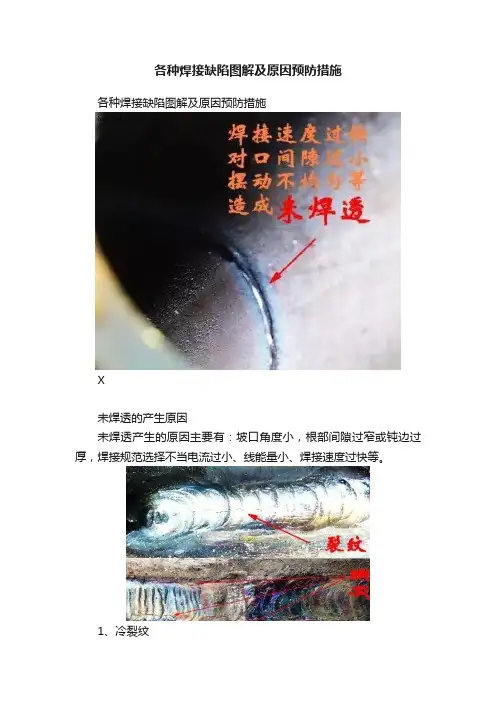
各种焊接缺陷图解及原因预防措施各种焊接缺陷图解及原因预防措施X未焊透的产生原因未焊透产生的原因主要有:坡口角度小,根部间隙过窄或钝边过厚,焊接规范选择不当电流过小、线能量小、焊接速度过快等。
1、冷裂纹冷裂纹的特征多出现在焊道与母材熔合线附近的热影响区中,多为穿晶裂纹。
冷裂纹无氧化色彩。
冷裂纹发生于或,高的含碳量和合金含量。
冷裂纹具有延迟性质,主要是延迟裂纹。
冷裂纹产生原因(和热影响区及熔合区)的淬火倾向严重,产生淬火组织,导致接头性能脆化。
含氢量较高,并聚集在处形成大量氢分子,造成非常大的局部压力,使接头脆化;磷含量过高同样产生冷裂纹。
存在较大的拉应力。
因氢的扩散需要时间,所以冷裂纹在焊后需延迟一段时间才出现。
由于是氢所诱发的,也叫氢致裂纹。
防止冷裂纹的措施选用碱性或,减少金属中氢的含量,提高金属塑性。
要烘干,焊缝及附近母材要去油、水、除锈,减少氢的来源。
工件焊前预热,焊后缓冷(大部分材料的温度可查表),可降低焊后冷却速度,避免产生淬硬组织,并可减少焊接。
采取减小焊接应力的工艺措施,如对称焊,小线能量的多层多道焊等,焊后进行清除应力的。
焊后立即进行去氢(后热)处理,加热到250℃,保温2~6h,使焊缝金属中的散氢逸出金属表面。
2、热裂纹(又称结晶裂纹)热裂纹的特征热裂纹可发生在焊缝区或热影响区,沿焊缝长度方向分布。
热裂纹的微观特征是沿晶界开裂,所以又称晶间裂纹。
因热裂纹在高温下形成,有氧化色彩。
焊后立即可见。
热裂纹产生原因。
焊缝金属的晶界上存在低熔点共晶体(含硫、磷、铜等杂质)。
接头中存在拉应力。
防止措施选用适宜的,严格控制有害杂质碳、硫、磷的含量。
Fe和FeS易形成低熔点共晶,其熔点为988℃,很容易产生热裂纹。
严格控制焊缝截面形状,避免突高,扁平过渡。
缩小结晶温度范围,改善焊缝组织,细化焊缝晶粒,提高塑性减少。
确定合理的参数,减缓焊缝的冷却速度,以减小焊接应力。
如采用小线能量,焊前预热,合理的焊缝布置等。
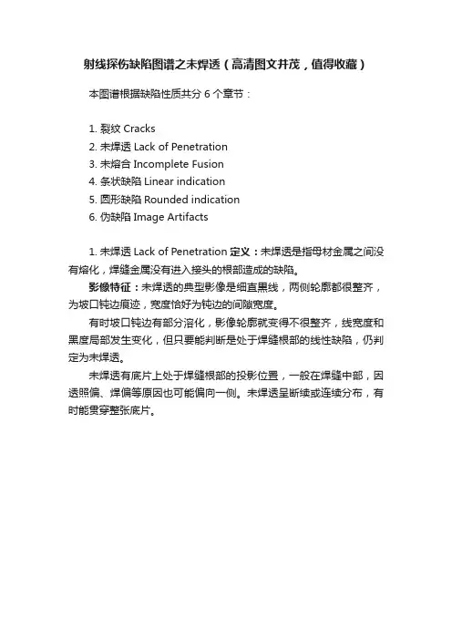
射线探伤缺陷图谱之未焊透(高清图文并茂,值得收藏)
本图谱根据缺陷性质共分6个章节:
1. 裂纹Cracks
2. 未焊透Lack of Penetration
3. 未熔合Incomplete Fusion
4. 条状缺陷Linear indication
5. 圆形缺陷Rounded indication
6. 伪缺陷Image Artifacts
1. 未焊透Lack of Penetration定义:未焊透是指母材金属之间没有熔化,焊缝金属没有进入接头的根部造成的缺陷。
影像特征:未焊透的典型影像是细直黒线,两侧轮廓都很整齐,为坡口钝边痕迹,宽度恰好为钝边的间隙宽度。
有时坡口钝边有部分溶化,影像轮廓就变得不很整齐,线宽度和黑度局部发生变化,但只要能判断是处于焊缝根部的线性缺陷,仍判定为未焊透。
未焊透有底片上处于焊缝根部的投影位置,一般在焊缝中部,因透照偏、焊偏等原因也可能偏向一侧。
未焊透呈断续或连续分布,有时能贯穿整张底片。

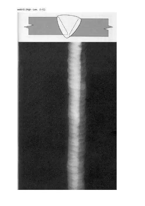
weld-01 (High - Low、高-低)welld-02 (Incomplete Root Fusion、根部未熔合)welld-03 (Insuffucient R einforcement、内凹)welld-04 (Excess Root Penetration、根部焊瘤)welld-07(Root Concavi t y、根部凹陷) (Root Concavi t y、根部凹陷)(Burn Through、烧穿) (Burn Through、烧穿)(Isolated Slag Inclusion、单个的夹渣) (Isolated Slag Inclusion、单个的夹渣)Wagon Track - Slag Line、线状夹渣线状夹渣(Interrun Fusion、内部未熔合)(Interrun Fusion、内部未熔合)welld-12(Lack of Sidewall Fusion、内侧未熔合)(Lack of Sidewall Fusion、内侧未熔合)welld-13(Porosity、气孔)(Porosity、气孔)welld-14(Cluster Porosity、链状气孔)(Cluster Porosity、链状气孔)welld-15(Hollow Bead、夹珠)(Hollow Bead、夹珠)welld-16(Transverse Crack、横向裂纹)(Transverse Crack、横向裂纹)welld-17(Centerline Crack、中心线裂纹)(Centerline Crack、中心线裂纹)welld-18(Root Crack、根部裂纹)(Root Crack、根部裂纹)welld-19(Tungsten Inclusion)夹钨(Tungsten Inclusion)夹钨。
常见焊接缺陷及图示
常见的缺陷有:裂纹、焊瘤、烧穿、弧坑、气孔、夹渣、咬边、未熔合、未焊透等,以及焊缝尺寸不符合要求、焊缝成形不良(如:长度不足,高度不足,未满焊)等。
1.气孔:
修复方法:打磨去除该段焊缝,重新焊接。
修复方法:打磨去除该段焊缝,重新焊接。
2.砂眼(焊接时气体或杂质在焊接构件内部或表面形成的小孔)
修复方法:打磨去除所有影响焊缝,重新焊接。
3.缩孔(焊接后在冷凝过程中收缩而产生的孔洞,形状不规则,孔壁粗糙,一般位于铸件的热节处。
)
5.
6.
7.
8.
9.
10.
11.
------来源网络,仅供参考。
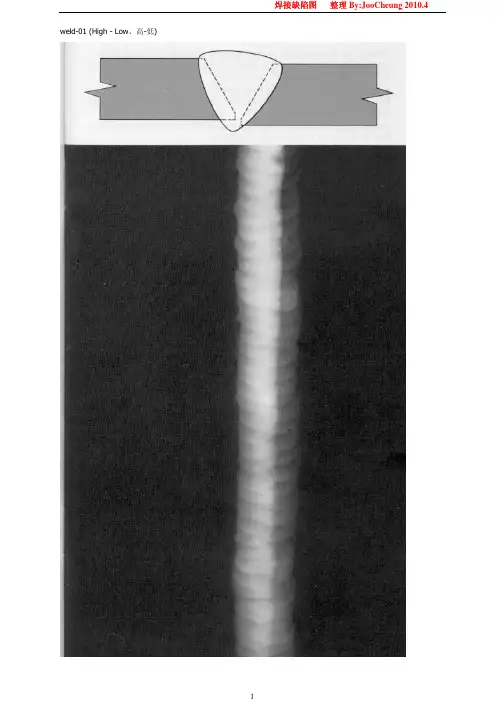
焊接缺陷图 整理By:JooCheung 2010.4 1 weld-01 (High - Low、高-低) 焊接缺陷图 整理By:JooCheung 2010.4
2 welld-02 (Incomplete Root Fusion、根部未熔合) 焊接缺陷图 整理By:JooCheung 2010.4
3 welld-03 (Insuffucient Reinforcement、内凹) 焊接缺陷图 整理By:JooCheung 2010.4
4 welld-04 (Excess Root Penetration、根部焊瘤)
welld-05 焊接缺陷图 整理By:JooCheung 2010.4
5 (External Undercut、外部咬肉)
welld-06 焊接缺陷图 整理By:JooCheung 2010.4
6 (Internal Undercut、内部咬肉)
welld-07 焊接缺陷图 整理By:JooCheung 2010.4
7(Root Concavity、根部凹陷) (Root Concavity、根部凹陷)
welld-08 焊接缺陷图 整理By:JooCheung 2010.4
8(Burn Through、烧穿) (Burn Through、烧穿)
welld-09 焊接缺陷图 整理By:JooCheung 2010.4
9(Isolated Slag Inclusion、单个的夹渣) (Isolated Slag Inclusion、单个的夹渣)
welld-10 焊接缺陷图 整理By:JooCheung 2010.4
10 Wagon Track - Slag Line、线状夹渣 线状夹渣
welld-11 (Interrun Fusion、内部未熔合) 焊接缺陷图 整理By:JooCheung 2010.4 11 (Interrun Fusion、内部未熔合)
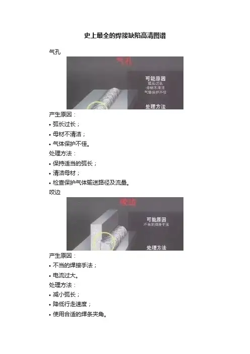
史上最全的焊接缺陷高清图谱气孔产生原因:•弧长过长;•母材不清洁;•气体保护不佳。
处理方法:•保持适当的弧长;•清洁母材;•检查保护气体输送路径及流量。
咬边产生原因:•不当的焊接手法;•电流过大。
处理方法:•减小弧长;•降低行走速度;•使用合适的焊条夹角。
未熔合产生原因:•“冷”焊工艺;•行走速度过慢;•行走速度过快。
处理方法:•增加电流;•采用正确的行走速度。
未焊透产生原因:•焊接规法偏小;•行走速度过慢;•行走速度过快;•接头尺寸不正确。
处理方法:•增加电流;•采用正确的行走速度。
焊缝余高偏大产生原因:•行走速度过慢;•焊接规范偏小。
处理方法:•加快行走速度;•增加电流。
未焊满产生原因:•填充金属不足。
处理方法:•减小行走速度。
根部内凹产生原因:•电流过大;•电弧过长;•钝边尺寸过小。
处理方法:•减小电流;•保持合适的弧长;•正确装配焊接接头。
焊缝不均匀产生原因:•不当的焊接手法。
处理方法•保持恒定的行走速度。
焊角尺寸不正确产生原因:•焊条夹角不合适。
处理方法:•采用正确的焊接手法。
焊瘤产生原因:•行走速度过慢。
处理方法:•使用正确的行走速度。
夹渣产生原因:•不当的焊接手法。
处理方法:•使用正确的焊接手法;•焊后清理每道焊缝。
•焊缝为什么会开裂热影响区裂纹产生原因:•氢含量过高;•高碳/合金含量的母材;•残余应力高。
处理方法:•使用低氢焊材;•控制焊缝金属的氢含量;•增加预热;•增加焊后热处理。
弧坑裂纹产生原因:•不恰当的填弧坑。
处理方法:•在焊缝末端使用分步退焊法;•使用不恰当的填弧坑机器设置。
横向裂纹产生原因:•氢含量过高;•焊接金属强度过大;•残余应力高。
处理方法:•增加预热;•使用低强度焊材(与设计要求一致);•增加焊后热处理。
纵向裂纹产生原因:•不恰当的宽深比;•低熔点杂质;•凹的焊缝表面。
处理方法:•使用宽深比在1:1-1.4:1范围之间; •限制熔深过大;•降低电压或行走速度。
罕见的焊接缺陷 (1)宇文皓月罕见的焊接缺陷(1)未焊透:母体金属接头处中间(X坡口)或根部(V、U坡口)的钝边未完全熔合在一起而留下的局部未熔合。
未焊透降低了焊接接头的机械强度,在未焊透的缺口和端部会形成应力集中点,在焊接件承受载荷时容易导致开裂。
(2)未熔合:固体金属与填充金属之间(焊道与母材之间),或者填充金属之间(多道焊时的焊道之间或焊层之间)局部未完全熔化结合,或者在点焊(电阻焊)时母材与母材之间未完全熔合在一起,有时也常伴随夹渣存在。
(3)气孔:在熔化焊接过程中,焊缝金属内的气体或外界侵入的气体在熔池金属冷却凝固前未来得及逸出而残留在焊缝金属内部或概况形成的空穴或孔隙,视其形态可分为单个气孔、链状气孔、密集气孔(包含蜂窝状气孔)等,特别是在电弧焊中,由于冶金过程进行时间很短,熔池金属很快凝固,冶金过程中发生的气体、液态金属吸收的气体,或者焊条的焊剂受潮而在高温下分解发生气体,甚至是焊接环境中的湿度太大也会在高温下分解出气体等等,这些气体来不及析出时就会形成气孔缺陷。
尽管气孔较之其它的缺陷其应力集中趋势没有那么大,但是它破坏了焊缝金属的致密性,减少了焊缝金属的有效截面积,从而导致焊缝的强度降低。
某钢板对接焊缝X射线照相底片V型坡口,手工电弧焊,未焊透某钢板对接焊缝X射线照相底片V型坡口,手工电弧焊,密集气孔(4)夹渣与夹杂物:熔化焊接时的冶金反应产品,例如非金属杂质(氧化物、硫化物等)以及熔渣,由于焊接时未能逸出,或者多道焊接时清渣不干净,以至残留在焊缝金属内,称为夹渣或夹杂物。
视其形态可分为点状和条状,其外形通常是不规则的,其位置可能在焊缝与母材交界处,也可能存在于焊缝内。
另外,在采取钨极氩弧焊打底+手工电弧焊或者钨极氩弧焊时,钨极崩落的碎屑留在焊缝内则成为高密度夹杂物(俗称夹钨)。
W18Cr4V(高速工具钢)-45钢棒对接电阻焊缝中的夹渣断口照片钢板对接焊缝X射线照相底片V型坡口,手工电弧焊,局部夹渣钢板对接焊缝X射线照相底片V型坡口,手工电弧焊,两侧线状夹渣钢板对接焊缝X射线照相底片V型坡口,钨极氩弧焊打底+手工电弧焊,夹钨(5)裂纹:焊缝裂纹是焊接过程中或焊接完成后在焊接区域中出现的金属局部破裂的表示。
常见的焊接缺陷〔1〕常见的焊接缺陷〔1〕未焊透:母体金属接头处中间〔X坡口〕或根部〔丫、U坡口〕的钝边未完全熔合在一起而留下的局部未熔合.未焊透降低了焊接接头的机械强度,在未焊透的缺口和端部会形成应力集中点,在焊接件承受载荷时容易导致开裂.〔2〕未熔合:固体金属与填充金属之间〔焊道与母材之间〕,或者填充金属之间〔多道焊时的焊道之间或焊层之间〕局部未完全熔化结合,或者在点焊〔电阻焊〕时母材与母材之间未完全熔合在一起,有时也常伴有夹渣存在.〔3〕气孔:在熔化焊接过程中,焊缝金属内的气体链状气孔根部未焊透中间未焊透坡面未熔合层间未熔合纵向裂纹〔热裂纹〕横向裂纹夹渣夹渣〔冷裂蚊F热影响区裂蚊〕或外界侵入的气体在熔池金属冷却凝固前未来得及逸出而残留在焊缝金属内部或外表形成的空穴或孔隙,视其形态可分为单个气孔、链状气孔、密集气孔〔包括蜂窝状气孔〕等,特别是在电弧焊中,由于冶金过程进行时间很短,熔池金属很快凝固,冶金过程中产生的气体、液态金属吸收的气体,或者焊条的焊剂受潮而在高温下分解产生气体,甚至是焊接环境中的湿度太大也会在高温下分解出气体等等,这些气体来不及析出时就会形成气孔缺陷.尽管气孔较之其它的缺陷其应力集中趋势没有那么大,但是它破坏了焊缝金属的致密性,减少了焊缝金属的有效截面积,从而导致焊缝的强度降低.w. .v某钢板对接焊缝X射线照相底片V型坡口,手工电弧焊,未焊透某钢板对接焊缝X射线照相底片V型坡口,手工电弧焊,密集气孔〔4〕夹渣与夹杂物:熔化焊接时的冶金反响产物,例如非金属杂质〔氧化物、硫化物等〕以及熔渣,由于焊接时未能逸出,或者多道焊接时清渣不干净,以至残留在焊缝金属内,称为夹渣或夹杂物.视其形态可分为点状和条状,其外形通常是不规那么的,其位置可能在焊缝与母材交界处,也可能存在于焊缝内.另外,在采用鸨极氩弧焊打底+手工电弧焊或者鸨极氩弧焊时,鸨极崩落的碎屑留在焊缝内那么成为高密度夹杂物〔俗称夹鸨〕.W18Cr4V 〔高速工具钢〕-45钢棒对接电阻焊缝中的夹渣断口照片w. .v钢板对接焊缝X射线照相底片V型坡口,手工电弧焊,两侧线状夹渣钢板对接焊缝X射线照相底片V型坡口,鸨极氩弧焊打底+手工电弧焊,夹鸨〔5〕裂纹:焊缝裂纹是焊接过程中或焊接完成后在焊接区域中出现的金属局部破裂的表现.焊缝金属从熔化状态到冷却凝固的过程经过热膨胀与冷收缩变化,有较大的冷收缩应力存在,而且显微组织也有从高温到低温的相变过程而产生组织应力,更加上母材非焊接部位处于冷固态状况,与焊接部位存在很大的温差,从而产生热应力等等, 这些应力的共同作用一旦超过了材料的屈服极限,材料将发生塑性变形,超过材料的强度极限那么导致开裂.裂纹的存在大大降低了焊接接头的强度,并且焊缝裂纹的尖端也成为承载后的应力集中点,成为结构断裂的起源.裂纹可能发生在焊缝金属内部或外部,或者在焊缝附近的母材热影响区内,或者位于母材与焊缝交界处等等.根据焊接裂纹产生的时间和温度的不同,可以把裂纹分为以下几类:a.热裂纹〔又称结晶裂纹〕:产生于焊缝形成后的冷却结晶过程中,主要发生在晶界上,金相学中称为沿晶裂纹,其位置多在焊缝金属的中央和电弧焊的起弧与熄弧的弧坑处,呈纵向或横向辐射状,严重时能贯穿到外表和热影响区.热裂纹的成因与焊接时产生的偏析、冷热不均以及焊条〔填充金属〕或母材中的硫含量过高有关.b.冷裂纹:焊接完成后冷却到低温或室温时出现的裂纹,或者焊接完成后经过一段w..v时间才出现的裂纹〔这种冷裂纹称为延迟裂纹,特别是诸如14乂而.丫8、18乂血.岫8、14MnMoNbB等合金钢种容易产生此类延迟裂纹,也称之为延迟裂纹敏感性钢〕.冷裂纹多出现在焊道与母材熔合线附近的热影响区中,其取向多与熔合线平行,但也有与焊道轴线呈纵向或横向的冷裂纹.冷裂纹多为穿晶裂纹〔裂纹穿过晶界进入晶粒〕,其成因与焊道热影响区的低塑性组织承受不了冷却时体积变化及组织转变产生的应力而开裂,或者焊缝中的氢原子相互结合形成分子状态进入金属的细微孔隙中时将造成很大的压应力连同焊接应力的共同作用导致开裂〔称为氢脆裂纹〕,以及焊条〔填充金属〕或母材中的磷含量过高等因素有关.c.再热裂纹:焊接完成后,如果在一定温度范围内对焊件再次加热〔例如为消除焊接应力而采取的热处理或者其他加热过程,以及返修补焊等〕时有可能产生的裂纹, 多发生在焊结过热区,属于沿晶裂纹,其成因与显微组织变化产生的应变有关.r-।।, 口■唆叱,」.J对接焊缝上的纵向外表裂纹与外咬边的荧光磁粉检测显示照片〔照片来源:日本EISHIN KAGAKU CO.,LTD〕合金钢板对接焊缝X射线照相底片V型坡口,气体保护焊-鸨极氩弧焊,横裂纹厚度14mm低合金钢板对接焊缝X射线照相底片,X型坡口,自动焊,纵向裂缝〔照片来源:?焊缝射线照相典型缺陷图谱?崔秀一张泽丰李伟编著〕〔6〕偏析:在焊接时因金属熔化区域小、冷却快,容易造成焊缝金属化学成分分布不均匀,从而形成偏析缺陷,多为条状或线状并沿焊缝轴向分布.〔7〕咬边与烧穿:这类缺陷属于焊缝的外部缺陷.当母体金属熔化过度时造成的穿w..v透〔穿孔〕即为烧穿.在母体与焊缝熔合线附近由于熔化过强也会造成熔敷金属与母体金属的过渡区形成凹陷,即是咬边.根据咬边处于焊缝的上下面,可分为外咬边〔在坡口开口大的一面〕和内咬边〔在坡口底部一面〕.咬边也可以说是沿焊缝边缘低于母材外表的凹槽状缺陷.其他的焊缝外部缺陷还有:焊瘤:焊缝根部的局部突出,这是焊接时因液态金属下坠形成的金属瘤.焊瘤下常会有未焊透缺陷存在,这是必须注意的.内凹或下陷:焊缝根部向上收缩低于母材下外表时称为内凹,焊缝盖面低于母材上外表时称为下陷.溢流:焊缝的金属熔池过大,或者熔池位置不正确,使得熔化的金属外溢,外溢的金属又与母材熔合.弧坑:电弧焊时在焊缝的末端〔熄弧处〕或焊条接续处〔起弧处〕低于焊道基体表面的凹坑,在这种凹坑中很容易产生气孔和微裂纹.焊偏:在焊缝横截面上显示为焊道偏斜或扭曲.增强高〔也称为焊冠、盖面〕过高:焊道盖面层高出母材外表很多,一般焊接工艺对于增强高的高度是有规定的,高出规定值后,增强高与母材的结合转角很容易成为应力集中处,对结构承载不利.以上的外部缺陷多容易使焊件承载后产生应力集中点,或者减小了焊缝的有效截面积而使得焊缝强度降低,因此在焊接工艺上一般都有明确的规定,并且常常采用目w..v视检查即可发现这些外部缺陷.焊接缺陷与检验〔一〕焊接缺陷 在焊接生产过程中,由于设计、工艺、操作中的各种因素的影响,往往会产生各种 焊接缺陷.焊接缺陷不仅会影响焊缝的美观,还有可能减小焊缝的有效承载面积, 造成应力集中引起断裂,直接影响焊接结构使用的可靠性.表3-6列出了常见的焊 接缺陷及其产生的原因.表3-6常见焊接缺陷 缺陷名 称 示* 意 图特征 产生原因气孔焊接时,熔池中的过饱和H 、N 以及冶金反响产 生的CO ,在熔池凝固时未能逸出,在焊缝中形成 的空穴 焊接材料不清洁;弧长太长,保护效果 差;焊接标准不恰当,冷速太快;焊前清 理不当裂纹热裂纹:沿晶开裂,具有氧化色泽,多在焊缝上, 焊后立即开裂冷裂纹:穿晶开裂,具有金属光泽,多在热影响 区,有延时性,可发生在焊后任何时刻热裂纹:母材硫、磷含量高;焊缝冷速 太快,焊接应力大;焊接材料选择不当 冷裂纹:母材淬硬倾向大;焊缝含氢量高;焊接剩余应力较大夹渣 焊后残留在焊缝中的非金属夹杂物 焊道间的熔渣未清理干净;焊接电流太小、焊接速度太快;操作不当咬边在焊缝和母材的交界处产生的沟槽和凹陷焊条角度和摆动不正确;焊接电流太大、 电弧过长 焊瘤焊接时,熔化金属流淌到焊缝区之外的母材上所 形成的金属瘤焊接电流太大、电弧过长、焊接速度太 慢;焊接位置和运条不当 未焊透 焊接接头的根部未完全熔透焊接电流太小、焊接速度太快;坡口角 w. 度太小、间隙过窄、钝边太厚</SPA.v焊接缺陷及其危害一般常见的焊接缺陷可分为四类:〔1〕焊缝尺寸不符合要求:如焊缝超高、超宽、过窄、上下差过大、焊缝过渡到母材不圆滑等.〔2〕焊接外表缺陷:如咬边、焊瘤、内凹、满溢、未焊透、外表气孔、外表裂纹等.〔3〕焊缝内部缺陷:如气孔、夹渣、裂纹、未熔合、夹鸨、双面焊的未焊透〔4〕焊接接头性能不符合要求:因过热、过烧等原因导致焊接接头的机械性能、抗腐蚀性能降低等.焊接缺陷对焊接构件的危害,主要有以下几方面:〔1〕引起应力集中.焊接接头中应力的分布是十分复杂的.但凡结构截面有忽然变化的部位,应力的分布就特别不均匀,在某些点的应力值可能比平均应力值大许多倍,这种现象称为应力集中.造成应力集中的原因很多,而焊缝中存在工艺缺陷是其中一个很重要的因素.焊缝内存在的裂纹、未焊透及其他带尖缺口的缺陷, 使焊缝截面不连续,产生突变部位,在外力作用下将产生很大的应力集中.当应力超过缺陷前端部位金属材料的断裂强度时,材料就会开裂破坏.〔2〕缩短使用寿命.对于承受低周疲劳载荷的构件,如果焊缝中的缺陷尺寸超过一定界限,循环一定周次后,缺陷会不断扩展,长大,直至引起构件发生断裂.〔3〕造成脆裂,危及平安.脆性断裂是一种低应力断裂,是结构件在没有塑性变形情况下,产生的快速突发性断裂,其危害性很大.焊接质量对产品的脆断有很大的影响.焊接时常发生的缺陷及预防方法一、气孔焊缝金属产生的气孔可分为:内部气孔,外表气孔,接头气孔.1.内部气孔:有两种形状.一种是球状气孔多半是产生在焊缝的中部.产生的原因:〔1〕焊接电流过大;〔2〕电弧过长;w..v(3)运棒速度太快;(4)熔接部位不洁净;(5)焊条受潮等.上述造成气孔原因如进行适当调整和注意焊接工艺及操作方法,就可以得到解决.2.面气孔:产生外表气孔的原因和解决方法:(1)母材含C、S、Si量高容易出现气孔.其解决方法或是更换母材,或是采用低氢渣系的焊条.(2)焊接部位不洁净也容易产生气孔.因此焊接部位要求在焊接前去除油污,铁锈等脏物.使用低氢焊条焊接时要求更为严格.(3)焊接电流过大.使焊条后半部药皮变红,也容易产生气孔.因此要求采取适宜的焊接标准.焊接电流最大限度以焊条尾部不红为宜.(4)低氢焊条容易吸潮,因此在使用前均需在350℃的温度下烘烤1小时左右.否那么也容易出现气孔.3.波接头气孔:使用低氢焊条往往容易在焊缝接头处出现外表和内部气孔,其解决方法:焊波接头时,应在焊缝的前进方向距弧坑9〜10mm处开始引弧,电弧燃烧后,先作反向运棒返向弧坑位置,作充分熔化再前进,或是在焊缝处引弧就可以预防这种类型的气孔产生.二、裂缝1.刚性裂缝:往往在焊接当中发现焊缝通身的纵裂缝,主要是在焊接时产生的应力造成的.在以下情况下焊接应力很大:(1)被焊结构刚性大;(2)焊接电流大,焊接速度快;(3)焊缝金属的冷却速度太快..v w. 因而在上述的情况下很容易产生纵向的长裂缝.解决方法:采用合理的焊接次序或者在可能的情况下工件预热,减低结构的刚性.特厚板和刚性很大的结构应采用低氢焊条使用适宜的电流和焊速.2.硫元素造成的裂缝:被焊母材的碳和硫高或偏析大时容易产生裂缝.解决方法:将焊件预热,或用低氢焊条.3.隙裂缝:毛隙裂缝是在焊敷金属内部发生,不开展到外部的毛状微细裂缝.考虑是焊敷金属受急速冷却而脆化,局部发生应力及氢气的影响.对此的预防方法是:使其焊件的冷却速度缓慢些,可能的条件下焊件进行预热,或者使用低氢焊条可得到满意的解决.三、电弧产生偏吹使用低氢焊条在直流电焊机上焊接时往往发生偏吹现象.可以用下面方法解决.1.线放在电弧偏吹的方向.2.线分成两个以上.3.电弧偏吹的方向进行焊接.4.取短弧操作.焊接缺陷与焊接质量检验一、焊接缺陷〔一〕焊接变形工件焊后一般都会产生变形,如果变形量超过允许值,就会影响使用.焊接变形的几个例子如图2-19所示.产生的主要原因是焊件不均匀地局部加热和冷却. 由于焊接时,焊件仅在局部区域被加热到高温,离焊缝愈近,温度愈高,膨胀也愈大.但是,加热区域的金属因受到周围温度较低的金属阻止,却不能自由膨胀;而冷却时又由于周围金属的牵制不能自由地收缩.结果这局部加热的金属存在拉应力, 而其它局部的金属那么存在与之平衡的压应力.当这些应力超过金属的屈服极限时,w..v将产生焊接变形;当超过金属的强度极限时,那么会出现裂缝.筒体纵焊鹫筒体环焊缝图2-噂焊接变形示意图〔二〕焊缝的外部缺陷1.焊缝增强过高如图2-20所示,当焊接坡口的角度开得太小或焊接电流过小时,均会出现这种现象.焊件焊缝的危险平面已从M-M平面过渡到熔合区的N-N 平面,由于应力集中易发生破坏,因此,为提升压力容器的疲劳寿命,要求将焊缝的增强高铲平.2.焊缝过凹如图2-21所示,因焊缝工作截面的减小而使接头处的强度降低.图2-加焊缝增高过强图2-21焊鹿过凹3.焊缝咬边在工件上沿焊缝边缘所形成的凹陷叫咬边,如图2-22所示.它不仅减少了接头工作截面,而且在咬边处造成严重的应力集中.w. .v4 .焊瘤熔化金属流到溶池边缘未溶化的工件上,堆积形成焊瘤,它与工件没有 熔合,见图2-23.焊瘤对静载强度无影响,但会引起应力集中,使动载强度降低.5 .烧穿如图2-24所示.烧穿是指局部熔化金属从焊缝反面漏出,甚至烧穿成 洞,它使接头强度下降.以上五种缺陷存在于焊缝的外表,肉眼就能发现,并可及时补焊.如果操作熟 练,一般是可以预防的.〔三〕焊缝的内部缺陷1 .未焊透未焊透是指工件与焊缝金属或焊缝层间局部未熔合的一种缺陷.未焊 透减弱了焊缝工作截面,造成严重的应力集中,大大降低接头强度,它往往成为焊 缝开裂的根源.2 .夹渣 焊缝中夹有非金属熔渣,即称夹渣.夹渣减少了焊缝工作截面,造成应 力集中,会降低焊缝强度和冲击韧性.3 .气孔 焊缝金属在高温时,吸收了过多的气体〔如H2〕或由于溶池内部冶金 反响产生的气体〔如CO 〕,在溶池冷却凝固时来不及排出,而在焊缝内部或外表 形成孔穴,即为气孔.气孔的存在减少了焊缝有效工作截面,降低接头的机械强度. 假设有穿透性或连续性气孔存在,会严重影响焊件的密封性. w. 焊蜃2凝边图"?焊寤.v图2-24烧穿4.裂纹焊接过程中或焊接以后,在焊接接头区域内所出现的金属局部破裂叫裂纹.裂纹可能产生在焊缝上,也可能产生在焊缝两侧的热影响区.有时产生在金属外表,有时产生在金属内部.通常根据裂纹产生的机理不同,可分为热裂纹和冷裂纹两类.〔1〕热裂纹热裂纹是在焊缝金属中由液态到固态的结晶过程中产生的,大多产生在焊缝金属中.其产生原因主要是焊缝中存在低熔点物质〔如FeS,熔点1193c〕, 它削弱了晶粒间的联系,当受到较大的焊接应力作用时,就容易在晶粒之间引起破裂.焊件及焊条内含S、Cu等杂质多时,就容易产生热裂纹.热裂纹有沿晶界分布的特征.当裂纹贯穿外表与外界相通时,那么具有明显的氢化倾向.〔2〕冷裂纹冷裂纹是在焊后冷却过程中产生的,大多产生在基体金属或基体金属与焊缝交界的熔合线上.其产生的主要原因是由于热影响区或焊缝内形成了淬火组织,在高应力作用下,引起晶粒内部的破裂,焊接含碳量较高或合金元素较多的易淬火钢材时,最易产生冷裂纹.焊缝中熔入过多的氢,也会引起冷裂纹.裂纹是最危险的一种缺陷,它除了减少承载截面之外,还会产生严重的应力集中,在使用中裂纹会逐渐扩大,最后可能导致构件的破坏.所以焊接结构中一般不允许存在这种缺陷,一经发现须铲去重焊.二、焊接的检验对焊接接头进行必要的检验是保证焊接质量的重要举措.因此,工件焊完后应根据产品技术要求对焊缝进行相应的检验,凡不符合技术要求所允许的缺陷,需及时进行返修.焊接质量的检验包括外观检查、无损探伤和机械性能试验三个方面. 这三者是互相补充的,而以无损探伤为主.w. .v〔一〕外观检查外观检查一般以肉眼观察为主,有时用5-20倍的放大镜进行观察.通过外观检查,可发现焊缝外表缺陷,如咬边、焊瘤、外表裂纹、气孔、夹渣及焊穿等.焊缝的外形尺寸还可采用焊口检测器或样板进行测量.〔二〕无损探伤隐藏在焊缝内部的夹渣、气孔、裂纹等缺陷的检验.目前使用最普遍的是采用X射线检验,还有超声波探伤和磁力探伤.X射线检验是利用X射线对焊缝照相,根据底片影像来判断内部有无缺陷、缺陷多少和类型.再根据产品技术要求评定焊缝是否合格.超声波探伤的根本原理如图2-25所示.1-工件2-焊箜3-陷A超声波* 5一探头图2-25越声波探伤原理示意图超声波束由探头发出,传到金属中,当超声波束传到金属与空气界面时,它就折射而通过焊缝.如果焊缝中有缺陷,超声波束就反射到探头而被接受,这时荧光屏上就出现了反射波.根据这些反射波与正常波比拟、鉴别,就可以确定缺陷的大小及位置.超声波探伤比X光照相简便得多,因而得到广泛应用.但超声波探伤往往只能凭操作经验作出判断,而且不能留下检验根据.w..v 对于离焊缝外表不深的内部缺陷和外表极微小的裂纹,还可采用磁力探伤.〔三〕水压试验和气压试验对于要求密封性的受压容器,须进行水压试验和〔或〕进行气压试验,以检查焊缝的密封性和承压水平.其方法是向容器内注入1.25 — 1.5倍工作压力的清水或等于工作压力的气体〔多数用空气〕,停留一定的时间,然后观察容器内的压力下降情况,并在外部观察有无渗漏现象,根据这些可评定焊缝是否合格.〔四〕焊接试板的机械性能试验无损探伤可以发现焊缝内在的缺陷,但不能说明焊缝热影响区的金属的机械性能如何,因此有时对焊接接头要作拉力、冲击、弯曲等试验.这些试验由试验板完成.所用试验板最好与圆筒纵缝一起焊成,以保证施工条件一致.然后将试板进行机械性能试验.实际生产中,一般只对新钢种的焊接接头进行这方面的试验.w. .v。
Radiograph Interpretation - WeldsIn addition to producing high quality radiographs, the radiographer must also be skilled in radiographic interpretation. Interpretation of radiographs takes place in three basic steps which are (1) detection, (2) interpretation, and (3) evaluation. All of these steps make use of the radiographer's visual acuity. Visual acuity is the ability to resolve a spatial pattern in an image. The ability of an individual to detect discontinuities in radiography is also affected by the lighting condition in the place of viewing, and the experience level for recognizing various features in the image. The following material was developed to help students develop an understanding of the types of defects found in weldments and how they appear in a radiograph.DiscontinuitiesDiscontinuities are interruptions in the typical structure of a material. These interruptions may occur in the base metal, weld material or "heat affected" zones. Discontinuities, which do not meet the requirements of the codes or specification used to invoke and control an inspection, are referred to as defects.General Welding DiscontinuitiesThe following discontinuities are typical of all types of welding.Cold lap is a condition where the weld filler metal does not properly fuse with the base metal or the previous weld pass material (interpass cold lap). The arc does not melt the base metal sufficiently and causes the slightly molten puddle to flow into base material without bonding.Porosity is the result of gas entrapment in the solidifying metal. Porosity can take many shapes on a radiograph but often appears as darkround or irregular spots or specks appearing singularly, in clusters or rows. Sometimes porosity is elongated and may have the appearance of having a tail This is the result of gas attempting to escape while the metal is still in a liquid state and is called wormhole porosity. All porosity is a void in the material it will have a radiographic density more than the surrounding area..Cluster porosity is caused when flux coated electrodes are contaminated with moisture. The moisture turns into gases when heated and becomes trapped in the weld during the welding process. Cluster porosity appear just like regular porosity in the radiograph but the indications will be grouped close together.Slag inclusions are nonmetallic solid material entrapped in weld metal or between weld and base metal. In a radiograph, dark, jagged asymmetrical shapes within the weld or along the weld joint areas are indicative of slag inclusions.Incomplete penetration (IP) or lack of penetration (LOP)occurs when the weld metal fails to penetrate the joint. It is one of the most objectionable weld discontinuities. Lack of penetration allows a natural stress riser from which a crack may propagate. The appearance on a radiograph is a dark area with well-defined, straight edges that follows the land or root face down the center of the weldment.Incomplete fusion is a condition where the weld filler metal does not properly fuse with the base metal. Appearance on radiograph: usually appears as a dark line or lines oriented in the direction of the weld seam along the weld preparation or joining area.Internal concavity or suck back is condition where the weld metal has contracted as it cools and has been drawn up into the root of the weld. On a radiograph it looks similar to lack of penetration but the line has irregular edges and it is often quite wide in the center of the weld image.Internal or root undercut is an erosion of the base metal next to the root of the weld. In the radiographic image it appears as a dark irregular line offset from the centerline of the weldment. Undercutting is not as straight edged as LOP because it does not follow a ground edge.External or crown undercut is an erosion of the base metal next to the crown of the weld. In the radiograph, it appears as a dark irregular line along the outside edge of the weld area.Offset or mismatch are terms associated with a condition where two pieces being welded together are not properly aligned. The radiographic image is a noticeable difference in density between the two pieces. The difference in density is caused by the difference in material thickness. The dark, straight line is caused by failure of the weld metal to fuse with the land area.Inadequate weld reinforcement is an area of a weld where the thickness of weld metal deposited is less than the thickness of the base material. It is very easy to determine by radiograph if the weld has inadequate reinforcement, because the image density in the area of suspected inadequacy will be more (darker) than the image density of the surrounding base material.Excess weld reinforcement is an area of a weld, which has weld metal added in excess of that specified by engineering drawings and codes. The appearance on a radiograph is a localized, lighter area in the weld. A visual inspection will easily determine if the weld reinforcement is in excess of that specified by the individual code involved in the inspection.Cracking can be detected in a radiograph only the crack is propagating in a direction that produced a change in thickness that is parallel to the x-ray beam. Cracks will appearas jagged and often very faint irregular lines. Cracks can sometimes appearing as "tails" on inclusions or porosity.Discontinuities in TIG weldsThe following discontinuities are peculiar to the TIG welding process. These discontinuities occur in most metals welded by the process including aluminum and stainless steels. The TIG method of welding produces a clean homogeneous weld which when radiographed is easily interpreted.Tungsten inclusions. Tungsten is a brittle and inherently dense material used in the electrode in tungsten inert gas welding. If improper welding procedures are used, tungsten may be entrapped in the weld. Radiographically, tungsten is more dense than aluminum or steel;therefore, it shows as a lighter area with a distinct outline on the radiograph.Oxide inclusions are usually visible on the surface of material being welded (especially aluminum). Oxide inclusions are less dense than the surrounding materials and, therefore, appear as dark irregularly shaped discontinuities in the radiograph.Discontinuities in Gas Metal Arc Welds (GMAW)The following discontinuities are most commonly found in GMAW welds.Whiskers are short lengths of weld electrode wire, visible on the top or bottom surface of the weld or contained within the weld. On a radiograph they appear as light, "wire like" indications.Burn through (icicles) results when too much heat causes excessive weld metal to penetrate the weld zone. Lumps of metal sag through the weld creating a thick globular condition on the back of the weld. On aradiograph, burn through appears as dark spots surrounded by light globular areas.。