YAG laser butt welding of AA6013 using silicon and magnesium containing filler powders
- 格式:pdf
- 大小:1.50 MB
- 文档页数:13
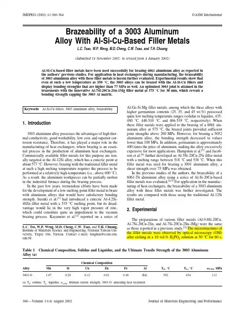
Brazeability of a3003Aluminum Alloy With Al-Si-Cu-Based Filler MetalsL.C.Tsao,W.P.Weng,M.D.Cheng,C.W.Tsao,and T.H.Chuang(Submitted14November2001;in revised form4January2002)Al-Si-Cu-based filler metals have been used successfully for brazing6061aluminum alloy as reported in the authors’previous studies.For application in heat exchangers during manufacturing,the brazeability of3003aluminum alloy with these filler metals is herein further evaluated.Experimental results show that even at such a low temperature as550°C,the3003alloys can be brazed with the Al-Si-Cu fillers and display bonding strengths that are higher than77MPa as well.An optimized3003joint is attained in the brazements with the innovative Al-7Si-20Cu-2Sn-1Mg filler metal at575°C for30min,which reveals a bonding strength capping the3003Al matrix.Keywords Al-Si-Cu fillers,3003aluminum alloy,brazeability 1.Introduction3003aluminum alloy possesses the advantages of high ther-mal conductivity,good workability,low cost,and superior cor-rosion resistance.Therefore,it has played a major role in the manufacturing of heat exchangers,where brazing is an essen-tial process in the production of aluminum heat exchangers. Commercially available filler metals for this purpose are usu-ally targeted at the Al-12Si alloy,which has a eutectic point at about577°C.However,brazing with the traditional filler metal at such a high melting temperature requires the process to be performed at a relatively high temperature(i.e.,above600°C). As a result,the aluminum workpieces can be partially molten in the industrial furnace during the brazing process.In the past few years,tremendous efforts have been made for the development of a low-melting-point filler metal to braze with aluminum alloys that would have satisfactory bonding strength.Suzuki et al.[1]had introduced a eutectic Al-4.2Si-40Zn filler metal with a535°C melting point,but its disad-vantage would lie in the very high vapor pressure of zinc, which could constitute quite an impediment to the vacuum brazing process.Kayamoto et al.[2]reported on a series of Al-Ge-Si-Mg filler metals,among which the three alloys with higher germanium contents(25,35,and45wt.%)possessed quite low melting temperature ranges(solidus to liquidus,435-480°C,448-510°C,and466-539°C,respectively).When these filler metals were applied to the brazing of a6061alu-minum alloy at575°C,the brazed joints provided sufficient joint strengths above200MPa.However,for brazing a5052 aluminum alloy,the bonding strength decreased to values lower than100MPa.In addition,germanium is approximately 400times the price of aluminum,making the alloy excessively expensive for most applications.Humpston et al.[3]and Jacob-son et al.[6]further developed an Al-5Si-20Cu-2Ni filler metal with a melting range between518°C and538°C.When this filler metal was used for brazing a3001aluminum alloy,a shear strength over75MPa was obtained.In the previous studies of the authors,the brazeability of a 6061-T6aluminum alloy using a series of Al-Si-20Cu-based filler metals was evaluated.[4,5]For application in the manufac-turing of heat exchangers,the brazeability of a3003aluminum alloy with these filler metals was further investigated.The results are compared with those using the traditional Al-12Si filler metal.2.ExperimentalThe preparations of various filler metals(Al-9.6Si-20Cu, Al-7Si-20Cu-2Sn,and Al-7Si-20Cu-2Sn-1Mg)were the same as those reported in a previous study.[1]The microstructures of the filler metals were observed by optical microscopy(OM) after etching in a10vol.%H3PO4solution at50°C for60s.L.C.Tso,W.P.Weng,M.D.Cheng,C.W.Tsao,and T.H.Chuang,Institute of Materials Science and Engineering,National Taiwan Uni-versity,Taipei106,Taiwan.Contact e-mail:tunghan@ccms.ntu.edu.tw.Table1Chemical Composition,Solidus and Liquidus,and the Ultimate Tensile Strength of the3003Aluminum Alloy(a)AlloyChemical CompositionTS,°C TL,°CUTS,MPa Mn Si Cu Zn Fe Al3003-O 1.070.280.120.010.48Bal.592654112(a)TS :solidus;TL:liquidus;UTS:ultimate tensile strength;3003-O:annealing heat treatment.JMEPEG(2002)11:360-364©ASM InternationalThe chemical composition,solidus,liquidus,and the ultimate strength of the as-annealed 3003aluminum alloy (3003-O)are shown in Table 1.For the evaluation of bonding strengths using these filler metals,3003aluminum plate specimens (1mm in thickness,25mm in length,and 10mm in width)were lapped for an overlap length of 3mm with a clearance of 0.2mm,as shown in Fig.1.The brazing process was conducted in a vacuum furnace at a pressure setting of 5×10⁻⁵torr.The brazing time was held constant for 30min.The cross-sections of the brazed joints were analyzed by an electron microana-lyzer (EMPA).3.Results and DiscussionThe melting temperatures (solidus and liquidus)of the filler metals in this study,as determined from the differential thermalanalysis (DTA)curves in Fig.2,are summarized in Table 2.It can be seen that both the solidus and liquidus of Al-9.6Si-20Cu are about 50°C lower than those of the Al-12Si filler metal.A further addition of 2%Sn to the ternary Al-Si-Cu alloy causes its melting temperature to drop about 20°C.The final Al-7Si-20Cu-2Sn-1Mg alloy carries its solidus and liquidus at 501°C and 522°C,respectively,which are much lower levels than those of the traditional Al-12Si filler metal.Table 2Solidus,Liquidus,and Melting Range of Filler Metals in This StudyFiller Metals T S ,°C T L ,°C ⌬T,°C Al-12Si57959314Al-9.6Si-20Cu 52454319Al-7Si-20Cu-2Sn50452622Al-7Si-20Cu-2Sn-1Mg50152221(a)T S :solidus;T L :liquidus;⌬T:meltingrange.Fig.2DTA curves of the filler metals in thisstudyFig.3Microstructures of (a )Al-9.6Si-20Cu,(b )Al-7Si-20Cu-2Sn,and (c )Al-7Si-20Cu-2Sn-1Mg fillermetalsFig.1Geometry and dimensions of the brazed specimens for tensile testingThe microstructure of the Al-9.6Si-20Cu alloy,as shown in Fig.3(a),is composed of Al-Cu and Al-Cu-Si eutectic phases, the CuAl2()intermetallic compound,and pure Si particles. The Si particles disappear in the Al-7Si-20Cu-2Sn and Al-7Si-20Cu-2Sn-1Mg alloys,as shown in Fig.3(b)and(c).Their microstructures contain a dendrite␣-Al solid solution and vari-ous eutectic phases.The bonding strengths of the3003joints brazed with vari-ous filler metals at various temperatures are demonstrated in Table3.Since the traditional Al-12Si filler metal possesses a eutectic point at about577°C(DTA-analyzed melting range, 579-593°C),any brazing process for this filler metal that is carried out at around this temperature is destined for failure. Not until the brazing temperature is raised to600°C can the 3003aluminum alloy then be bonded with this filler metal.The bonding strength in this case is higher than the ultimate strength of the3003aluminum alloy(112MPa),and,conse-quently,the tensile specimens will fracture in the3003alumi-num alloy matrix.When the Al-9.6Si-20Cu filler metals are used to braze the3003aluminum alloy at550°C,the bonding strength is77±14MPa.However,while the Al-7Si-20Cu-2Sn and Al-7Si-20Cu-2Sn-1Mg filler metals are applied to brazing at550°C,the bonding strengths are improved to83±15MPa and95±12MPa,respectively.As the brazing temperature is raised to575°C using the Al-7Si-20Cu-2Sn-1Mg filler metal,a sound joint with a bond-ing strength higher than the ultimate strength of the3003alu-minum alloy is achieved(Table3).Figure4(a)shows the mi-crostructure of the joint for such an optimized case in which a 3003aluminum alloy is brazed with Al-7Si-20Cu-2Sn-1Mg at 575°C for30min.The lap joint width is about200m,which is much narrower than that of a6061aluminum brazement using the same filler metal and under the same brazing condi-tions(Fig.4b).It can be attributed to the much higher solidus of the3003aluminum alloy(648°C)vs that of the6061 aluminum alloy(592°C),resulting in a larger temperature difference between the solidus of the Al-matrix and the brazing temperature(575°C)for the3003aluminum alloy.The EPMA element mapping in Fig.5reveals that the Al content in the lap joint decreases distinctly after brazing.The depletion of Al is countered by the enrichment of the Si and Cu elements(Fig.5c and d).However,the locations of the Si-rich and Cu-rich phases are separate.It also has been found that the Sn and Mg elements have vanished in the lap joint(Fig.5e and f),which implies that both elements have dissolved into the 3003Al-matrix.In contrast with the microstructure shown in Fig.3(c),the EPMA results indicate that the composition of the filler metal greatly changed during the brazing reaction with the3003aluminum alloy.4.ConclusionsIn summary,it can be concluded that sound joints can be obtained for the brazing of the3003aluminum alloy using the developed Al-Si-Cu-based filler metals at lower temperatures than those that the traditional Al-12Si filler metal has adopted in the brazing process.When the Al-7Si-20Cu-2Sn-1Mg filler metal is applied to brazing at575°C for30min,the bonding strength is higher than the ultimate strength of the3003alu-minum alloy.Under this condition,the brazing process is des-tined to failure using the traditional Al-12Si filler metal.It was also found that the3003aluminum joint possesses a much narrower reaction zone compared to that of a6061aluminum joint brazed with the same filler under the same brazing con-ditions(i.e.,575°C for30min).Table3Brazing Temperatures and Bonding Strengths of the3003Aluminum Brazements in This StudyFiller MetalsBondingTemperature,°CBondingStrength,MPaFractureLocationAl-12Si575Failed Lap joint Al-12Si600>112(a)Matrix Al-9.6Si-20Cu55077±14Lap joint Al-7Si-20Cu-2Sn55083±15Lap joint Al-7Si-20Cu-2Sn-1Mg55095±12Lap joint Al-7Si-20Cu-2Sn-1Mg575>112(a)Matrix (a)The ultimate tensile strength of the3003aluminumalloy.Fig.4Microstructure of the3003aluminum joint(a)in comparison with that of the6061aluminum joint and(b)after brazing with the Al-7Si-20Cu-2Sn-1Mg filler metal at575°C for30minFig.5EMPA element mapping of the3003aluminum butt joint brazed with the Al-7Si-20Cu-2Sn-1Mg filler metal at575°C for30minReferences1.K.Suzuki,M.Kagayama,and Y.Takeuchi:“Eutectic Phase Equilib-rium of Al-Si-Zn System and Its Applicability for Lower Temperature Brazing,”J.Jpn Inst.Light Met.,1993,43,pp.533-38.2.T.Kayamoto,J.H.Kim,S.Saito,and T.Onzawa:“Brazing of Al-MgAlloy and Al-Mg-Si Alloy with Al-Ge Based Filter Metals,”Proceed-ings of Workshop of the Japanese Welding Society,1994,12, pp.495-501.3.G.Humpston,S.P.S.Sangha,and D.M.Jacobson:“New Filler Metalsand Process for Fluxless Brazing of Aluminium Engineering Alloys,”Mater.Sci.Technol.,1995,11,pp.1161-67.4.L.C.Tsao,T.C.Tsai,C.S.Wu,and T.H.Chuang:“Brazeability of the6061-T6Aluminum Alloy with Al-Si-20Cu-Based Filler Metals,”J.Mater.Eng.Performance,2001,10(6),pp.705-09.5.M.S.Yeh,L.C.Tsao,T.C.Tsai,C.S.Wu,and T.H.Chuang:“Devel-opment of a Low-Melting-Point Filler Metal for Brazing Aluminum Alloys,”Metall.Mater.Trans.A,2000,31A,pp.2239-45.6.D.M.Jacobson,G.Humpston,and S.P.S.Sangha:“A New Low-Melting-Point Aluminum Braze,”Welding J.,1996,75,pp.243s-50s.。
MIG 焊接铝材:重要问题和最佳实践铝,尤其是薄规格铝,提出了一些独特的焊接挑战。
对于许多人来说,GTAW 是首选工艺,但GMAW 提供了一些明显的好处:更高的沉积速率、更少的操作员培训和更高的生产率。
这些好处带来了一些挑战,即送丝和选择正确类型的填充金属和设备。
然而,这些挑战很容易解决,我们现在将探讨其中的一些。
纯铝是一种相对较软的金属,具有多种用途,但需要添加一种或多种合金以增加其强度并添加适合不同应用的其他品质。
常见的合金有:铜、镁、硅、锰和锌。
它们由它们的序列号标识:系列合金组1xxx 99% 最低铝纯度2xxx 铜3xxx 锰4xxx 硅5xxx 镁6xxx 镁硅7xxx 锌8xxx 其他填充金属问:如何确定使用哪种填充金属?答:虽然通常通过匹配抗拉强度来选择钢填充金属,但在选择铝填充金属时,强度只是考虑因素之一。
通常,几种不同的铝合金填充金属可以与任何铝合金母材一起使用,或者在将不同合金焊接在一起时使用。
在选择填充金属时,考虑到贱金属成分易于焊接联合设计稀释(当填充焊丝和母材在焊接熔池中结合以在焊缝中形成不同的化学成分时)焊缝强度开裂倾向延展性服务中的腐蚀颜色匹配,如果材料经过阳极氧化处理不同的填充金属在不同程度上解决了这些问题。
一般来说,如果强度是主要考虑因素,则填充金属应在拉伸、屈服和延展性方面与母材紧密匹配。
大多数消耗品制造商以及AWS 提供的信息列出了每种基础合金的填充金属的这些考虑因素的相对价值。
问:有没有通用的铝填充金属?答:虽然没有铝填充金属能满足所有需求,但4043 和5356 是最常见的两种,占铝填充金属销售的大部分。
它们可与最广泛使用的铝合金母材一起使用。
霍巴特兄弟最近通过开发其Smootharc™4043 和Smootharc™5356 焊丝扩展了其产品线,与竞争对手的产品相比,这些焊丝具有出色的进给性、良好的润湿性和优异的评级。
4043 是焊工的最爱,因为它的硅合金增加了焊接的便利性并提供了更好的熔池控制。
第51卷第11期2020年11月中南大学学报(自然科学版)Journal of Central South University(Science and Technology)V ol.51No.11Nov.2020选区激光熔化AlSi10Mg合金镜的表面性能韩潇1,2,康楠3,焦建超1,2,王超1,2(1.北京空间机电研究所,北京,100094;2.先进光学遥感技术北京市重点实验室,北京,100094;3.西北工业大学凝固技术国家重点实验室,陕西西安,710072)摘要:基于激光增材制造技术适用于复杂轻量化结构光学元件的快速成形,且采用同种材料一体化光机结构能够降低空间光学成像系统的温度敏感性,提高稳定性,利用选区激光熔化(SLM)技术制备全铝空间光学相机用AlSi10Mg铝合金反射镜。
研究结果表明:采用SLM制备的AlSi10Mg铝合金组织致密(相对密度大于99.5%),且退火后力学性能优异;通过单点金刚石车削(SPDT)获得光学级表面,表面粗糙度达8~ 13nm,面形精度达到0.28λ(λ为波长,λ=632nm)。
该研究结果可以应用于空间光学反射镜的设计与制造。
关键词:增材制造;选区激光熔化;铝镜;空间光学;表面性能;金刚石车削中图分类号:TB34;TG113文献标志码:A开放科学(资源服务)标识码(OSID)文章编号:1672-7207(2020)11-3088-05Surface characteristics of selective laser melted AlSi10Mg mirrorsHAN Xiao1,2,KANG Nan3,JIAO Jianchao1,2,WANG Chao1,2(1.Beijing Institute of Space Mechanics and Electricity,Beijing100094,China;2.Beijing Key Laboratory of Advanced Optical Remote Sensing Technology,Beijing100094,China;3.State Key Laboratory of Solidification Processing,Northwestern Polytechnical University,Xi'an710072,China)Abstract:Considering that additive manufacturing(AM)technologies is adapted for the optical components with complex lightweight structure,using the opto-mechanical structure with the same material can reduce temperature sensitivity,selective laser melting(SLM)technology was utilized to fabricate the AlSi10Mg mirror for aluminum alloy space optical sensor.The results show that the relative density of as-fabricated AlSi10Mg sample is above99.5%,and the tensile strength and the ductility are excellent.The single point diamond turning(SPDT)is appliedto deliver the optical surface with thoughness of8−13nm and accuracy of0.28λ(λ=632nm).The results can be used to manufacture the lightweight space optical mirrors.Key words:additive manufacturing;selective laser melting;aluminum mirror;space optical;surface characteristics;diamond turningDOI:10.11817/j.issn.1672-7207.2020.11.010收稿日期:2020−08−26;修回日期:2020−09−22基金项目(Foundation item):国家自然科学基金资助项目(U1537105)(Project(U1537105)supported by the Natural National Science Foundation of China)通信作者:韩潇,博士,高级工程师,从事空间光学遥感器先进制造及其材料性能评价技术研究;E-mail:hanxiao1998@126.com第11期韩潇,等:选区激光熔化AlSi10Mg合金镜的表面性能随着空间光学遥感技术的迅速发展,高分辨率轻质空间光学相机已成为各国研究热点。
第 2 期第 164-171 页材料工程Vol.52Feb. 2024Journal of Materials EngineeringNo.2pp.164-171第 52 卷2024 年 2 月Ti预处理的SiC f/SiC与镍基高温合金复合铸件的界面组织与强度Microstructure and strength of composite castinginterface between Ti pretreated SiC f/SiCand Ni-based superalloy林国标*,朱付虎,赵斯文(北京科技大学材料科学与工程学院,北京100083)LIN Guobiao*,ZHU Fuhu,ZHAO Siwen(School of Materials Science and Engineering,University ofScience and Technology Beijing,Beijing 100083,China)摘要:由SiC f/SiC复合材料与K403镍基高温合金熔体制备的一体化铸件,冷却到室温时会出现自行断裂。
通过采用Ti 粉埋覆包渗工艺在1100 ℃下对SiC f/SiC表面进行预处理,并在适当工艺下与K403镍基高温合金熔体进行陶瓷型精密铸造,成功实现SiC f/SiC与K403镍基高温合金的一体化成形和界面的牢固结合。
结果表明:Ti预处理层平均厚度为17 μm 左右,Ti向SiC f/SiC渗透、扩散和反应,形成含TiC,Ti3SiC2,Ti5Si3C x,SiC相的显微组织;经过与高温镍基金属液复合铸造后,预处理层演变成厚约120 μm的界面反应层,其典型界面组织为Ni2Si+C+Al4C3+ M C(M主要含Ti及少量的Cr,Mo,W)。
预处理层的存在减轻Ni与SiC的有害石墨化反应,缓解高温金属液对SiC f/SiC的热冲击,形成的界面反应层降低热膨胀系数失配造成的热应力,使得SiC f/SiC与K403一体化铸件结合界面的室温剪切强度达到63.5 MPa。
2024 年第 44 卷航 空 材 料 学 报2024,Vol. 44第 1 期第 143 – 151 页JOURNAL OF AERONAUTICAL MATERIALS No.1 pp.143 – 151引用格式:冯振宇,陈翥仪,张雪峰,等. 激光选区熔化Al-Mg-Sc-Zr合金各向组织与损伤容限性能[J]. 航空材料学报,2024,44(1):143-151.FENG Zhenyu,CHEN Zhuyi,ZHANG Xuefeng,et al. Microstructure and damage tolerance properties in different directions of selective laser melted Al-Mg-Sc-Zr alloy[J]. Journal of Aeronautical Materials,2024,44(1):143-151.激光选区熔化Al-Mg-Sc-Zr合金各向组织与损伤容限性能冯振宇1*, 陈翥仪2, 张雪峰3, 夏晓宇2, 邹 君4*(1.中国民航大学 科技创新研究院,天津 300300;2.中国民航大学 中欧航空工程师学院,天津 300300;3.中国航空制造技术研究院,北京100024;4.中国民航大学 安全科学与工程学院,天津 300300)摘要:研究激光选区熔化(selective laser melting,SLM)技术成形Al-Mg-Sc-Zr合金材料不同取向的显微组织特征、拉伸和损伤容限性能。
结果表明:YZ截面为细小的等轴晶和粗大的柱状晶组成的双峰组织,XY截面由细小的等轴晶组成;0°和90°方向屈服强度、抗拉强度均超过500 MPa,各向异性较小,但堆积层间存在的未熔合缺陷使得90°方向断裂伸长率明显低于0°方向;0°和90°CT试样K IC分别为21.41 MPa·m1/2和20.89 MPa·m1/2,在柱状晶区域裂纹扩展阻抗低,导致90°CT试样K IC稍小;显微组织和缺陷是影响裂纹扩展性能各向异性的主要因素,在近门槛区未熔合缺陷起主导作用,当裂纹面平行于水平方向时裂纹扩展速率更快;在稳态扩展区显微组织的影响起主导作用,当裂纹面平行于水平方向时为穿晶断裂,裂纹扩展阻抗较高,裂纹扩展速率较低。
MaterialsScienceandEngineeringA426(2006)250–262Nd:YAGlaserbuttweldingofAA6013usingsiliconandmagnesiumcontainingfillerpowders
ReinholdBraun∗GermanAerospaceCenter,InstituteofMaterialsResearch,K¨oln,GermanyReceived30November2005;receivedinrevisedform31March2006;accepted11April2006
AbstractAluminiumalloy6013sheetwasbuttweldedusinga3kWNd:YAGlaseranddifferentfillerpowders.Twokindsoffillermetalswereused:gasatomisedpowdersofthealuminiumalloysAlMg5,AlSi12,AlSi12Mg5andAlSi10Mg,aswellasmixturesofpowdersoftheelementsAlandSiandthebinaryalloysAl–5Mg,Al–5Zr,Al–5CrandAl–10Mn.Microstructure,hardness,tensilepropertiesandcorrosionbehaviouroftheweldswereinvestigatedintheas-weldedT4andT6conditionsandafterapost-weldheattreatmenttotheT6temper.Theweldregionexhibitedadendriticcellularstructureinthefusionzoneandapartiallymeltedzoneadjacenttothefusionboundaries.Thehardnessofthefusionzonedependeduponthefillermetalsused.Post-weldartificialagingtotheT6temperimprovedthehardness,beingassociatedwithprecipitationofstrengtheningphases,asconfirmedbytransmissionelectronmicroscopy.Jointefficienciesachievedforpost-weldheattreatedjointsrangedfrom80to90%.Strengthsofweldsintheas-weldedT6conditionwerelowerduetothesoftenedfusionzoneandheataffectedzone,beingbetween70and75%oftheultimatetensilestrengthofthebasealloy6013–T6.OptimumtensilepropertieswereobtainedwithjointsmadewiththefillerpowderAlSi12.Reasonabletensilepropertieswereachievedforweldsmadewithmixturesofelementalandbinaryalloypowders,buttheydidnotreachthoseofjointsmadewithaluminiumalloypowders.ThedispersoidformingelementsZr,CrandMnaddedtoamixedAl–7Sipowderdidnotprovebeneficialeffectsonweldquality.Whenexposedtoanintermittentacidifiedsaltsprayfog,jointsintheas-weldedT4andpost-weldheattreatedT6conditionsexhibitedcorrosionbehavioursimilartothatofthebasesheetinthetempersT4andT6.As-welded6013–T4jointsweresusceptibletostresscorrosioncrackingwhenimmersedinanaqueoussolutionof0.6MNaCl+0.06MNaHCO3.Sensitivitytoenvironmentally
assistedcrackingwasassociatedwithgrainboundaryprecipitatesintheheataffectedzone.©2006ElsevierB.V.Allrightsreserved.
Keywords:Laserbeamwelding;Aluminiumalloys;Fillerpowders;Mechanicalproperties;Corrosionbehaviour
1.IntroductionRequirementsofweightsavings,improvementoffueleffi-ciencyandreductionofatmosphericpollutionhaveincreasedthedemandofthetransportationindustriesforlightweightstruc-tures[1].Tomeetlegislativeregulationsandmarketneedsandtoretaincompetitivenessoftheirproducts,manufacturershavebeenforcedtoexploreadvancedmaterialsandjoiningtech-niques.Theuseofaluminiuminautomotiveapplicationsisgrowingowingtoadvantageouspropertiesofaluminiumalloys,includinghighstiffnesstoweightratio,goodformability,goodcorrosionresistanceandrecyclingpotential[2].Thishasdrivendevelopmentsin5000and6000seriesaluminiumalloystoexpandtheirrangeofapplications[2,3].Nonheat-treatable5000
∗Tel.:+4922036012457;fax:+492203696480.
E-mailaddress:reinhold.braun@dlr.de.
seriesalloysarefavouredforinteriorstructuralcomponents,whileheat-treatable6000seriesalloysareusedforouterskinpanelsduetotheirhigherstrengthafterpaintbakingandfree-domfromL¨udersbandproblems[4].TheoccurrenceofL¨uderslinesincomponentsduringtheformingprocessdeterioratesthehighsurfacequalityrequiredforexteriorskinpanels.InEuropealloy6016isthemainautomotiveskinalloyduetoitshighformability,whereasalloy6111ispreferredinNorthAmericabecauseofitshighfinalstrengthanddentresistance[5].Laserbeamweldingisanattractivejoiningtechniqueforalu-miniumalloys,beingwidelyusedinindustrialproduction[6,7].Theadvantagesarehighweldingspeed,lowdistortion,manu-facturingflexibilityandeaseofautomation.WeldsareproducedusingCO2andNd:YAGlaserbeams.WhereasCO2lasershave
thepotentialofweldingmaterialwithhighthicknessorusinghighweldingspeedsduetothehighbeampower,thelattertypeoflaserallowsopticalfibrestoguidethelasertothefocusingoptics[8].Aluminiumalloysabsorbthelasermoreefficiently
0921-5093/$–seefrontmatter©2006ElsevierB.V.Allrightsreserved.doi:10.1016/j.msea.2006.04.033R.Braun/MaterialsScienceandEngineeringA426(2006)250–262251asthelaserwavelengthdecreases[1].TheNd:YAGlaserwithacharacteristicwavelengthof1.06mprovidesbettercouplingwithaluminiumthantheCO2laser,whichhasacharacteris-ticwavelengthof10.6m.Furthermore,theabsorptionofthelaserbeamincreasesdrasticallywhenakeyholeisformedduetomultiplereflectionsofthebeaminthekeyhole.Difficultiesoccurringwithlaserbeamweldingofaluminiumalloysarehotcracking,porosity,lossofalloyingelementsandgrainboundarymeltingintheheataffectedzone[1,6,9].Intheautomotiveindustry,theuseoftailor-weldedblanksmadefromaluminiumoffersconsiderableweightandcostreduction[1,10].Toachievethetargetsregardingoperationalcost,manufacturingcostandstructuralweight,airframemanu-factureshaveadoptedintegralconstructioninthemanufacturingprocess,replacingtheconventionalbuilt-upstructure[11,12].FortheaircraftAirbusA318,mechanicallyfastenedstiffenersoflowerfuselageshellshavebeensubstitutedbystringersattachedtotheskinusingCO2laserwelding.Thisjoiningprocessis