SCE a fully integrated software tool for Beowulf cluster system
- 格式:pdf
- 大小:690.71 KB
- 文档页数:17
iAbout the T utorialEclipse is an integrated development environment (IDE) for Java and other programming languages like C, C++, PHP, and Ruby etc. Development environment provided by Eclipse includes the Eclipse Java development tools (JDT) for Java, Eclipse CDT for C/C++, and Eclipse PDT for PHP, among others.This tutorial will teach you how to use Eclipse in your day-2-day life while developing any software project using Eclipse IDE. We will give special emphasis on Java project. AudienceThis tutorial has been prepared for beginners to help them understand basic functionality of Eclipse tool. After completing this tutorial, you will find yourself at a moderate level of expertise in using Eclipse IDE from where you can take yourself to next levels. PrerequisitesWe assume you are going to use Eclipse IDE to handle all levels of Java projects development. So it will be good if you have knowledge of software development using any programming language specially Java programming.Copyright & Disclaimer© Copyright 2015 by Tutorials Point (I) Pvt. Ltd.All the content and graphics published in this e-book are the property of Tutorials Point (I) Pvt. Ltd. The user of this e-book can retain a copy for future reference but commercial use of this data is not allowed. Distribution or republishing any content or a part of the content of this e-book in any manner is also not allowed without written consent of the publisher. We strive to update the contents of our website and tutorials as timely and as precisely as possible, however, the contents may contain inaccuracies or errors. Tutorials Point (I) Pvt. Ltd. provides no guarantee regarding the accuracy, timeliness or completeness of our website or its contents including this tutorial. If you discover any errors on our website or inthistutorial,******************************************iT able of ContentsAbout the Tutorial (i)Audience (i)Prerequisites (i)Copyright & Disclaimer (i)Table of Contents .................................................................................................................................... i i 1.OVERVIEW (1)What is Eclipse? (1)Licensing (1)Eclipse Releases (1)2.INSTALLATION (3)Downloading Eclipse (3)Installing Eclipse (3)Launching Eclipse (4)3.EXPLORE WINDOWS (5)Parts of an Eclipse Window (5)Using Multiple Windows (6)4.EXPLORE MENUS (7)Typical Eclipse Menus (7)Brief Description of Menus (8)Customizing Menus (8)5.EXPLORE VIEWS (9)About Views (9)Organizing Views (9)Moving Views (9)Creating View Folders (10)Opening a view (10)6.PERSPECTIVES (13)What is a Perspective? (13)Opening a Perspective (13)Switching between Perspectives (13)Closing a Perspective (14)Customizing a Perspective (14)7.WORKSPACES (16)About Eclipse Workspace (16)UI Elements for Managing the Workspace (16)8.CREATE JAVA PROJECT (18)Opening the New Java Project wizard (18)Using the New Java Project wizard (18)Viewing the Newly Created Project (20)9.CREATE JAVA PACKAGE (21)Opening the New Java Package wizard (21)Using the New Java Package Wizard (21)Viewing the Newly Created Package (22)10.CREATE JAVA CLASS (23)Opening the New Java Class Wizard (23)Using the New Java Class Wizard (23)Viewing the Newly Created Java class (24)11.CREATE JAVA INTERFACE (25)Opening the New Java Interface Wizard (25)Using the New Java Interface Wizard (25)Viewing the Newly Created Java Interface (26)12.CREATE XML FILE (27)Opening the New XML File wizard (27)Using the New XML File wizard (28)Viewing the Newly Created XML File (29)13.JAVA BUILD PATH (30)Setting the Java Build Path (30)14.RUN CONFIGURATION (31)Creating and Using a Run Configuration (31)15.RUNNING A PROGRAM (33)Running a Java Program (33)16.CREATE JAR FILES (35)Opening the Jar File wizard (35)Using the Jar File wizard (35)17.CLOSE PROJECT (37)Why Close a Project? (37)How to Close a Project? (37)Closed Project in Package Explorer (38)18.REOPEN PROJECT (39)Reopening a Closed Project (39)19.BUILD PROJECT (40)Building a Java Project (40)20.DEBUG CONFIGURATION (42)Creating and Using a Debug Configuration (42)21.DEBUGGING A PROGRAM (44)Debugging a Java Program (44)22.PREFERENCES (48)Setting Preferences (48)23.CONTENT ASSIST (50)Using Content Assist (50)24.QUICK FIX (52)Using Quix Fix (52)25.HOVER HELP (54)Using Hover Help (54)26.SEARCH MENU (56)Searching the Workspace (56)27.NAVIGATION (58)Navigating the Eclipse Workspace (58)Open Type (58)Open Type in Hierarchy (60)Open Resource (61)28.REFACTORING (63)Refactoring using Eclipse (63)29.ADD BOOKMARKS (64)About Bookmarks (64)Adding a Bookmark (64)Opening the Bookmarks View (64)Using the Bookmarks View (65)30.TASK MANAGEMENT (66)Managing Tasks (66)Opening the Tasks View (67)Using the Tasks View (67)31.INSTALL PLUGINS (69)Locating and Installing Plug-ins (69)32.CODE TEMPLATES (73)Using Code Templates (73)Modifying/Adding code templates (74)33.SHORTCUTS (75)About Shortcuts (75)34.RESTART OPTION (78)Restarting Eclipse (78)35.TIPS & TRICKS (79)36.WEB BROWSERS (81)Internal Web Browser (81)Eclipse 7What is Eclipse?In the context of computing, Eclipse is an integrated development environment (IDE) for developing applications using the Java programming language and other programming languages such as C/C++, Python, PERL, Ruby etc.The Eclipse platform which provides the foundation for the Eclipse IDE is composed of plug-ins and is designed to be extensible using additional plug-ins. Developed using Java, the Eclipse platform can be used to develop rich client applications, integrated development environments, and other tools. Eclipse can be used as an IDE for any programming language for which a plug-in is available.The Java Development Tools (JDT) project provides a plug-in that allows Eclipse to be used as a Java IDE, PyDev is a plugin that allows Eclipse to be used as a Python IDE, C/C++ Development Tools (CDT) is a plug-in that allows Eclipse to be used for developing application using C/C++, the Eclipse Scala plug-in allows Eclipse to be used an IDE to develop Scala applications and PHPeclipse is a plug-in to eclipse that provides complete development tool for PHP.LicensingEclipse platform and other plug-ins from the Eclipse foundation is released under the Eclipse Public License (EPL). EPL ensures that Eclipse is free to download and install. It also allows Eclipse to be modified and distributed.Eclipse ReleasesEvery year, since 2006, the Eclipse foundation releases the Eclipse Platform and a number of other plug-ins in June.1.Eclipse8Eclipse 9Downloading EclipseYou can download eclipse from /downloads/. The download page lists a number of flavors of eclipse.The capabilities of each packaging of eclipse are different. Java developers typically use Eclipse Classic or Eclipse IDE for developing Java applications.The drop down box in the right corner of the download page allows you to set the operating system on which eclipse is to be installed. You can choose between Windows, Linux and Mac. Eclipse is packaged as a zip file.Installing EclipseTo install on windows, you need a tool that can extract the contents of a zip file. For example you can use:∙7-zip ∙PeaZip ∙ IZArcUsing any one of these tools, extract the contents of the eclipse zip file to any folder of your choice.2.Launching EclipseOn the windows platform, if you extracted the contents of the zip file to c:\, then you can start eclipse by using c:\eclipse\eclipse.exeWhen eclipse starts up for the first time it prompts you for the location of the workspace folder. All your data will be stored in the workspace folder. You can accept the default or choose a new location.1011If you select "Use this as the default and do not ask again", this dialog box will not come up again. You can change this preference using the Workspaces Preference Page. See the Preference tutorialpage for more details.Eclipse 12Parts of an Eclipse WindowThe major visible parts of an eclipse window are:∙Views ∙Editors (all appear in one editor area) ∙Menu Bar ∙ ToolbarAn eclipse perspective is the name given to an initial collection and arrangement of views and an editor area. The default perspective is called java. An eclipse window can have multiple perspectives open in it but only one perspective can be active at any point of time. A user can switch between open perspectives or open a new perspective. A perspective controls what appears in some menus and tool bars.3.EclipseA perspective has only one editor area in which multiple editors can be open. The editor area is usually surrounded by multiple views. In general, editors are used to edit the project data and views are used to view the project metadata. For example, the package explorer shows the java files in the project and the java editor is used to edit a java file.The eclipse window can contain multiple editors and views but only one of them is active at any given point of time. The title bar of the active editor or view looks different from all the others.The UI elements on the menu bar and tool bar represent commands that can be triggered by an end user.Using Multiple WindowsMultiple Eclipse Windows can be open at the same time. To open a new window, click on the Windows menu and select the New Window menu item.Each window can have a different perspective open in them. For example you could open two Eclipse windows one in the Java perspective and the other in the Debug perspective. The window showing the Java perspective can be used for editing the java code and the window showing the debug perspective can be used for debugging the application being developed.13Eclipse 14T ypical Eclipse MenusThe typical menus available on the menu bar of an Eclipse window are:∙File menu ∙Edit menu ∙Navigate menu ∙Search menu ∙Project menu ∙Run menu ∙Window menu ∙ Help menu4.Plug-ins can add new menus and menu items. For example when the java editor is open, you will see the Source menu and when the XML editor is open, you will see the Design menu. Brief Description of Menus15Customizing MenusThe visible menu items on a menu depend on the installed plug-ins and customization done using the Customize Perspective dialog box.16Eclipse 17About ViewsEclipse views allow users to see a graphical representation of project metadata. For example the project navigator view presents a graphical representation of the folders and files associated with a project and properties view presents a graphical representation of an element selected in another view or editor.An eclipse perspective can show any number of views and editors. All editor instances appear in a single editor area, whereas views are placed inside view folders. A workbench window can display any number of view folders. Each view folder can display one or more views. Organizing ViewsThe following picture shows four views arranged in a view folder.The picture given below shows the same four views arranged in two view folders.5.Moving ViewsTo move a view from one view folder to another, just click on the view title and drag to the title bar area of another view folder. The green line shown below is a result of dragging the title bar of the Properties view from one view folder to the title bar area of another view folder. The Properties view can be moved to where the green line is by releasing the mouse button and sending out a drop event.Creating View FoldersView folders can be dynamically created by dragging the title bar of a view to anywhere outside the editor area and title bar of another view folder. As you drag the title bar around, green lines will indicate where exactly the new view folder will be created.Moving the drag icon to the bottom of a window allows you to create a view folder that spans the entire width of the window. Moving the drag icon to the left or right edge of window allows you to create a view folder that spans the entire height of the window.18Opening a viewTo open a view, click on the Window menu and select the Show View menu item.19Clicking on the Other menu item brings up the Show View dialog box that allows you to locate and activate a view.20The views are organized by category. To quickly locate a view, just type the name of a view into the filter text box. To open a view, select it and click on the OK button. The subsequent pages of this tutorial introduce you to a number of useful views.21End of ebook previewIf you liked what you saw…Buy it from our store @ https://22。

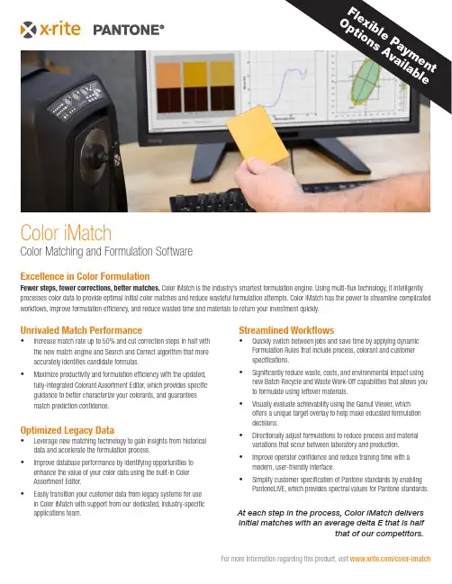
Streamlined Workflows•Quickly switch between jobs and save time by applying dynamic Formulation Rules that include process, colorant and customer specifications.•Significantly reduce waste, costs, and environmental impact using new Batch Recycle and Waste Work-Off capabilities that allows you to formulate using leftover materials.•Visually evaluate achievability using the Gamut Viewer, which offers a unique target overlay to help make educated formulation decisions.• Directionally adjust formulations to reduce process and material variations that occur between laboratory and production.• Improve operator confidence and reduce training time with a modern, user-friendly interface.•Simplify customer specification of Pantone standards by enabling PantoneLIVE, which provides spectral values for Pantone standards.Unrivaled Match Performance•Increase match rate up to 50% and cut correction steps in half with the new match engine and Search and Correct algorithm that more accurately identifies candidate formulas.•Maximize productivity and formulation efficiency with the updated, fully-integrated Colorant Assortment Editor, which provides specific guidance to better characterize your colorants, and guarantees match prediction confidence.Optimized Legacy Data• Leverage new matching technology to gain insights from historical data and accelerate the formulation process.•Improve database performance by identifying opportunities to enhance the value of your color data using the built-in Color Assortment Editor.•Easily transition your customer data from legacy systems for use in Color iMatch with support from our dedicated, industry-specific applications team.Color Matching and Formulation SoftwareExcellence in Color FormulationFewer steps, fewer corrections, better matches. Color iMatch is the industry’s smartest formulation engine. Using multi-flux technology, it intelligently processes color data to provide optimal initial color matches and reduce wasteful formulation attempts. Color iMatch has the power to streamline complicated workflows, improve formulation efficiency, and reduce wasted time and materials to return your investment quickly.At each step in the process, Color iMatch delivers initial matches with an average delta E that is halfthat of our competitors.For more information regarding this product, visit /color-imatchColor iMatche n t ai l a b l eX-Rite is either a registered trademark or trademark of X-Rite, Incorporated in the United States and/or other countries. PANTONE©, PantoneLIVE and other Pantone trademarks are the property of Pantone LLC. All other trademarks or registered trademarks are the property of their respective owners. © X-Rite, Inc. 2020. All rights reserved. L10-668-EN (10/20)Service Support and WarrantyX-Rite’s color analysis and measurement solutions are engineered and manufactured to the most rigorous quality standards. These standards are backed by comprehensive global service, superior phone and web support, and preventative maintenance options to optimize your long-term investment. We have developed service support and warranty plans that are unique to your organization’s specific products and needs. Learn more by reviewing our service offerings on our website at: /page/service-warranty . Still unsure of what you need? Contact us directly at:************************Management access is available through a unique Management configuration. Server-based configurations are also available. Ask your sales rep for more details.Measurement Conditions Reflectance, Transmission, Reflectance / Transmission, Over Light / Over Dark, SCI / SCEColor Differences FMCII, CIE DL*, Da*, Db*, CIE DL*, DC*, DH*, Hunter DL, Da, Db, All Attributes of CIELab, CIELch or HunterLab, CMC (l:c), CIE2000 (l:c:h), and more. Ask your sales rep for your specific needs.Color Spaces CIE L*a*b*, CIE L*C*h*, Hunter Lab, CIE (XYZxy)Illuminants D50, D55, D65, D75, F2, F7, F11, C, A, Horizon, TL84, Ultralume 3000, CIE LED, and more. Ask your sales rep for your specific needs.Observers 2 degree,10 degreeStandard IndicesWhiteness [ASTM E313, CIE, GANZ, Berger, Stensby, Taube, Tappi], Yellowness [ASTM E313, D1925], Opacity [Contrast Ratio, Tappi], Strength [SWL, Summed, Weighted Sum], Haze, Munsell Notation, Orange Juice, Gloss [ASTM E429, Gloss60], Grey Scale [ISO 105, Staining, Color Change], Metamerism, Color Constancy Index, APHA, Gardner Color Index, ASTM Color Index, Saybolt Color Index, AATCC TM203 Light Blocking Index, DIN55979 Blackness Index, G7 Substrate Compensation Configuration Options Basic, Professional, Management, Satellite, Online Editions Databases MS Access, MS SQL Server Experience Level Beginner to Advanced Import/Export Format CxF, JB5, MIF, QTXLanguages Supported English, French, German, Spanish, Italian, Portuguese, Japanese, ChineseSupported DevicesCi7860, Ci7800, Ci7600, Ci7500, Ci64, Ci62, Ci4200, Ci52, VS3200, 964, 962, CE-7000A, Color i5, Color i7, eXact, eXact XP , SP62, SP64 and most other industry instrumentsSpecificationsFor more information regarding this product, visit /color-imatch。
ESP Alchemist Version 5.2.1SCC Client InterfaceInstallation InstructionsInstalling Alchemist SCC InterfaceHardware and Software Requirements•ESP Alchemist 5.2.1•SCC-compliant IDE•Windows 98 and laterNote: ESP Alchemist SCC Interface was tested with Windows Visual Studio and IBM VisualAge for Java. Because IDEs may integrate SCC implementations differently, other SCC-compliant IDEs may not behave as documented.Installing the software from a CD-ROM4.Insert the ESP Alchemist CD into a CD drive.5.Follow the instructions in the installation wizard. See the ESP Alchemist SCCInterface Installation Parameters table below for installation details.Installing the software from the Cybermation web site1.Connect to your company’s portal on the Cybermation web site and navigate to theAlchemist installation location.2.Double-click on the setup.exe icon.3.Follow the instructions in the installation wizard. See the ESP Alchemist SCCInterface Installation Parameters table below for installation details. Uninstalling the software1.From the Start menu, select Settings > Control Panel > Add/Remove Programs.2.Select ESP Alchemist SCC Interface and click Change/Remove.3.Click OK to confirm that you want to uninstall the software, and follow theinstructions in the uninstallation wizard..ESP Alchemist SCC Interface Installation ParametersParameter DescriptionUserid The Alchemist user ID. It must have access toAlchemist libraries. It is not case sensitive.Zone Name The name of the Alchemist zone where you want tostore the source code.Alchemist IP Address or Domain Name The ESP Alchemist server IP address. The server IP address may be either in hostname or numeric format. It is defined in the Alchemist server.RMS Port The Request Manager Server port number. It isdefined in the Alchemist server.CXS Port The Component Export Server port number. It isdefined in the Alchemist server.Department Name The primary security group for the Alchemist userID. May be optional depending on your Alchemistserver configuration.Multiple Source-Code Control ProvidersIt is possible to have more than one SCC-compliant provider installed on your computer. When you install ESP Alchemist SCC, you can specify whether you want ESP Alchemistto be your default SCC provider. To change the default SCC, you must edit the Windows Registry file:1.In the Start menu, select Run...2.In the Open field, type regedit.3.Navigate to theHKEY_LOCAL_MACHINE\SOFTWARE\SourceCodeControlProvider\InstalledSCCProviders key.4.This key lists string values for every SCC provider. Review to ensure that the ESPAlchemist entry is Software\Cybermation\Alchemist.5.Navigate to HKEY_LOCAL_MACHINE\SOFTWARE\SourceCodeControlProviderkey.6.The ProviderRegKey entry specifies the default SCC provider.•If you want Alchemist to be the default SCC provider, enterSoftware\Cybermation\Alchemist as the value of ProviderRegKey.•If you want to change the default SCC provider, enter the value of one of the other providers listed in the InstalledSCCProviders sub-key.7.In the Registry menu, select Exit to exit the Registry Editor.Additional DocumentationWhen you install ESP Alchemist SCC Interface, the ESP Alchemist SCC User’s Guide in Adobe Portable Document Format (PDF) is automatically installed. For additional Alchemist documentation, including ESP Alchemist Messages and Codes, you should install the ESP Alchemist 5.2.1 Online Documentation package, either from the ESP Alchemist Documentation CD or from your Cybermation customer portal web site.Trademark NoticesCybermation is a registered trademark of Cybermation Inc.Microsoft, Windows and Visual C++ are registered trademarks of Microsoft Corporation.IBM and VisualAge are registered trademarks of International Business Machines Corporation.Java is a trademark of Sun Microsystems, Inc.All other brand and product names are trademarks or registered trademarks of their respective companies.。

acrobat 英文专业版Title: Adobe Acrobat Professional A Comprehensive Guide.Introduction.Adobe Acrobat Professional is a powerful tool that revolutionizes the way we handle, manage, and interact with PDF documents. It's not just a simple PDF reader; it's a complete suite of features designed to enhance productivity, collaboration, and security in the digital workspace. Inthis comprehensive guide, we'll delve into the various capabilities of Adobe Acrobat Professional, explore itsuses in different industries, and discuss why it remains an indispensable tool for professionals worldwide.What is Adobe Acrobat Professional?Adobe Acrobat Professional is the industry-leading software for creating, managing, and optimizing PDF documents. It's a comprehensive PDF solution that offers arange of advanced features such as PDF editing, form creation and filling, document conversion, OCR (Optical Character Recognition), security and compliance tools, and more. With Acrobat Professional, users can work seamlessly with PDF files, regardless of their origin or format.Key Features of Adobe Acrobat Professional.1. PDF Editing and Creation: Acrobat Professional allows users to create new PDF documents from scratch or convert existing files into PDF format. It also provides robust editing tools, enabling users to modify PDF content, including text, images, and pages.2. Forms and Filling: The software offers a user-friendly interface for creating interactive PDF forms. Users can design forms, add fields, and set validationrules to ensure data integrity. Acrobat Professional also allows for form filling, enabling users to populate PDF forms with data, save them, and submit them electronically.3. Document Conversion: Acrobat Professional boastspowerful conversion capabilities, converting PDF files into editable formats such as Word, Excel, or PowerPoint. It also converts scanned documents into editable text using OCR technology, eliminating the need for manual data entry.4. Security and Compliance: The software provides robust security features, including password protection, digital signatures, and encryption, to ensure the integrity and confidentiality of PDF documents. It also complies with various industry standards and regulations, making it suitable for use in legal, financial, and healthcare industries.5. Collaboration and Sharing: Acrobat Professional facilitates collaboration among team members by allowing users to share and review PDF documents. It integrates seamlessly with cloud storage solutions, enabling easy sharing and access to documents from anywhere.Applications of Adobe Acrobat Professional in Different Industries.1. Legal Industry: Lawyers and legal professionals rely on Acrobat Professional to handle sensitive andconfidential documents. The software's security features, such as password protection and digital signatures, ensure the authenticity and integrity of legal documents. Additionally, Acrobat Professional's conversioncapabilities help lawyers convert scanned court documents into editable formats for easier editing and review.2. Financial Services: In the financial industry, Acrobat Professional is used to create, manage, and distribute financial reports, contracts, and other important documents. The software's PDF editing and conversion features enable financial analysts and accountants to modify and share documents seamlessly. Its compliance with financial regulations ensures thatsensitive financial information remains secure.3. Healthcare: Healthcare professionals use Acrobat Professional to handle patient records, medical reports, and other confidential health information. The software's OCR capabilities enable doctors and nurses to convertscanned medical documents into editable text, improving workflow and efficiency. Acrobat Professional's security features also ensure the privacy and security of patient data.Conclusion.Adobe Acrobat Professional is an invaluable tool for professionals across industries. Its comprehensive set of features, including PDF editing, form creation, document conversion, security, and compliance tools, makes it a must-have for anyone working with PDF documents. Whether you're a lawyer managing legal cases, a financial analyst preparing financial reports, or a healthcare professional handling patient records, Acrobat Professional can help you streamline your workflow, improve collaboration, and ensure the security and integrity of your documents.。
PS501-SCASCA is short for “Safety Code Analysis”. In order to be able to use ST (Structured Text), FBD (Function Block Diagrams) and LD (Ladder Diagrams) for safety programming in CoDeSys 2.3, you have to follow certain coding guidelines.SCA can read your CoDeSys project and check it against those guidelines, flagging any problems.The user interface of SCA resembles that of CoDeSys very closely, so you should already be familiar with most of what you see.1. Installation NotesPC Hardware/Software Requirements:Any standard PC with Windows OS like XP Professional (32 bit) or Windows Vista or Windows7 will support the installation of SCA. Your PC shall have adequate memory (SCA needs around 2 MB only) and necessary administrator rights. SCA works as a stand-alone piece of software independent of Control Builder Plus installation and takes only a few seconds to complete the installation. However this depends on the speed of your processor.Click on the “.exe” file provided to start the installation process. Make sure that the necessary “.msi” file is located in the same directory as of the exe file. You will be guided by the software to complete the simple installation process.2. Workflow for project analysis–Export the project from CoDeSys–In the CoDeSys main menu, select “Project > Build”.–Make sure that CoDeSys reports no errors or warnings.–In the main menu, select “Project > Export”.–Ctrl-click to unselect “Workspace” and …PROFIsafe“ folder and then click “OK”.–Select a location and filename to save the export to, and click “Save”.–Open the exported file in SCA–In SCA, press “Ctrl-O”, or–in the main menu, select “File > Open CoDeSys export...”, or–click the “Open” button on the far left of the toolbar.–In the file open dialog, select the file just exported from CoDeSys.–You can also drag and drop a file onto the SCA window instead.–SCA immediately analyses your project and displays any problems found in the message list on the bottom.–Click on a message to display the source of the affected module and to and highlight the exact location where this prob-lem occurred.–Hover the mouse pointer over the selected message to see a resolution suggestion. (You may need to select “Options > Enable tooltips” first.)–Press F1, or select “Help > Help on this problem” from the main menu, to call up a help page on the problem selected.You can also right-click on any message and select “Help” from the context menu.–If you want to concentrate on the more serious problems first, select “Options > Show only errors” from the main menu.(This will add a message stating that you disabled warnings to remind you.)–If you want to tackle all problems of the same type together, select “Sort > by problem number” from the main menu.–Apply any changes required to your sources in CoDeSys. You don’t have to close the export in SCA in order to do this.–Repeat until SCA doesn’t show problems any more.–To reopen the export last opened:–Type “Ctrl-N”, or–in the main menu, select “File > Reopen”, or–click on the file name displayed in the toolbar.–To open an export recently opened:–In the main menu, select it under “File > Open recently used”, or–click on the small arrow next to the file name displayed in the toolbar, and select the export from the list displayed.–Print reports as needed.3. Format of the problem messages3.1. ExampleError 0180: Datatypes (H 9): Direct complex type declarations in variable lists are not allowed.3.2. ExplanationEach message contains the following parts:–Severity - this may be one of–“Error” - major problem that you must remove;–“Warning” - minor problem that you must remove;–“Manual” - a situation where SCA cannot determine whether a problem really exists or not.Print the “Manual check items” report and manually check for these problems;–“Remark” - additional information.–Problem type number.–Location, given by–name of the POU, global variable list, or type declaration, followed by–line or network number in parentheses. If the problem occurred in a POU,–“H” indicates a line number in the declaration header,–“B” indicates a line number in the body of an ST POU, and–“N” indicates a network number in an FBD or LD POU.–The problem message.4. Library definition filesIn order to be able to correctly check certain of the coding guidelines, SCA needs to know the definitions of POUs and variab-les contained in libraries. Some libraries are known to SCA by default (see Help for more details).If your project references libraries other than the standard libraries, you must provide the information contained in these libraries to SCA as follows.–Open your library project in CoDeSys 2.3.–Make sure the library project compiles without errors and warnings.–Export the complete library project from CoDeSys, as described above.–Open the export file in SCA.–In the main menu, select “File > Save library definition...”.–The save dialog opens in the “Library definitions” subfolder of the directory where SCA is installed.Save the library definition file only here, as SCA will otherwise not be able to find it.–If, in projects using the library, it is referenced by a different name, replace the name provided by SCA by that name.–Click “Save” to save the library definition.2 PS501-SCA | Read Me 3ADR020066K0202。
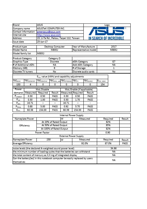
TEC BASETEC MEMORY TEC GRAPHIC TEC dGfx_add TEC STORAGE TEC TVTEC AUDIOETEC_MAX15040000154Measured Required ResultMeasured Required Result P LOWEST 0.300.50PASS 0.300.50PASS P Off 0.30 1.00PASS 0.30 1.70PASS P Idle 16.71----16.71---P Sleep 0.88 5.00PASS 0.92 5.70PASS E TEC 60.38154.00PASS60.39154.00PASSWResultW Result PASSG7NA Discrete audio cardsProduct Category M80CJCategory D M80CJ0.90Power FactorEfficiencyGraphics Type# of Additional dGfx Internal Power SupplyNameplate Power Memory (GB)Discrete TV tuners Issue date 25-Jan-172017Model Name Product type Year of Manufacture Model family list Desktop ComputerM80CJ Representative modelBrandCompany name Contact information Internet site Address LogoASUSASUSTeK COMPUTER INC.******************15, Li-Te Rd., Peitou, Taipei 112, Taiwan Discrete NA 8NoPower demand E TEC value (kWh) and capability adjustmentsAverage Efficiency 92.0%87.0%External Power SupplyAt 50% of Rated Output 85%At 100% of Rated Output 82%1NodGfx Category Add dGfx Category # of StorageWoL Disable WoL Enable (if applicable)Measured RequiredAt 20% of Rated Output 82%Can the battery[ies] in this notebook computer be easily replaced by users themselvesNANameplate Power 230Measured Required the minimum number of loading cycles that the batteries can withstand 34.66NA noise levels (the declared A-weighted sound power level)the total content of mercury as X,X mg of integrated displayNA4. The power management feature is enabled by default.The measurement methodologyECMA-383, Measuring the Energy Consumption of Personal Computing ProductsThe instrumentation, set-up and circuits used for electrical testing are accordance with ECMA-383Test voltage in V and frequency in Hz Total harmonic distortion of the electricity supply system 230V, 50Hz <21. Power management is a process that allows displays and computers (CPU, hard drive, etc.) to enter low-power states when sitting idle.12. Users can adjust how long your computer waits before sleeping or hibernating. Please refer to the user manual or website of O.S. provider for further information.13. Lowest power state means the state with the lowest power demand found in a computer. This mode may be entered or left by either a mechanical means or via automatic means14. Idle state means a state of a computer in which the operating system and other software havecompleted loading, a user profile has been created, the computer is not in sleep mode, and activity is limited to those basic applications that the operating system starts by default9. The computer is automatically set to sleep after 30 minutes of user inactivity.2. Inactive displays with enabled power management enter low-power modes by turning off monitor output,which can save $10 to $30(USD) per monitor annually3. The low power modes of inactive computers can involve reducing power consumption or spinning down the hard disk, which can save $15 to $45(USD) per desktop computer annually.10. To wake your computer, click the mouse, press power button, or press any key on the keyboard.11. For windows system, Notebook Computers will enter into hibernation after 360 minutes5. Sleep is a power-saving state that allows a computer to quickly resume full-power operation (typically within several seconds) when users want to start working again.6. Hibernation is a power-saving state designed primarily for laptops. Of all the power-saving states in Windows, hibernation uses the least amount of power.7. Hybrid sleep is designed primarily for desktop computers. Hybrid sleep is a combination of sleep and hibernate. When hybrid sleep is turned on, putting your computer into sleep automatically puts your computer into hybrid sleep. Hybrid sleep is typically turned on by default on desktop computers.8. The display is automatically set to sleep after 10 minutes of user inactivity.。
BOSE ProfessionalControlSpace®Designer™ software 5.5June 4, 2019Revision: 1.4GeneralThis release of ControlSpace Designer and firmware adds the following features:1.Support for EX-1280, EX-440C, EX-12AEC2.Support for CC-1D, CC-2D, and CC-3D digital zone controllers3.Updated ArrayEQ for ArenaMatch4.Updated SpeakerEQ files for ArenaMatchThis release of ControlSpace Designer and firmware fixes various issues including:Various CSD I/O Issues1.Fixed an issue where CSD was showing that it was still in the "online" state when the connected PC isdisconnected from the ControlSpace network.2.Fixed an issue where changing the Project Address automatically reset the Dante Endpoints and theyneeded to be updated manually.3.If a Parameter Set is changing Levels on an EX1280C Inputs, Outputs or Gains, the Levels not be setcorrectly if the channels are muted.4.Fixed issue where the ESP-880A and ESP-1240A were showing Dante Inputs and Outputs in the "SPToolkit" even though Dante is not available for these devices.5.If the CSD Project Address is changed, and new Dante Devices added to the Project, those devices willnow be assigned addresses consistent with the Project Address.6.Hardware Manager now displays the correct network mode (Static / DHCP) for the MSA12X7.Notes saved within a Logic Design Window are now saved.8.Fixed an issue where Control Space Designer was showing more Input Channels for a PowerMatch devicethan actually physically exist.9.Fixed issue where ControlSpace Designer Hardware Manager was not showing the correct FirmwareVersion for PowerShare Amplifiers.10.Fixed issue when updating the IP Address of multiple devices at one time (such as changing theControlSpace Designer Project Address) did not update and reboot CC-64s.11.Fixed issue where user was unable to add Dante I/O to Parameter Sets.12.Line drawn in project view from the Amplink output on DSP will now connect to any of the Amplinkinputs on amplifiers.13.CSD now displays more than 10 user defined channel names for Dante Output modules.14.Dante Endpoint IP addresses are changed to match updated Project Address.15.Fixed an issue where PowerMatch entered a Fault mode when uploading a design more than 21 times.3rd Party Mics1.Fixed an issue where the "Mute" function for the SHURE-310 Control Panel did not function correctly andmute the Mic.General Issues1.Grouped Input/Output Levels on PowerMatch devices can no longer be set to non-rounded values.2.Change channel count is now available for matrix mixer in right-click menu.3.Fixed an issue where a CC-16 connected to an EX-1280C would display duplicate characters whencontrolling a selector.4.Fixed an issue where designs created in CSD5.4 that included a CC16 generated a red power LED (systemfault) on EX-1280C.5.Grouped Dante Outputs are now functioning with the Master Fader while on line with CSD.6.Dynamic Routing has been fixed for the EX-1280C.ControlSpace Remote1.If the loaded .csp file used by Control Space Remote is changed and saved, ControlSpace Remote Builderwill now prompt the user notifying them the file has been updated.2.ControlSpace Remote now updates changes made to Group Level Sliders outside of Control SpaceRemote.3.When loading a file into ControlSpace Remote builder, the Level Bar now shows the actual level.FirmwareFirmware included in this release:CSRVersion 2.6 Builder and app are required.Known Issues, Defects and LimitationsThe following are the known issues and defects with this release. Information included here can be useful when troubleshooting issues with software or hardware operation.General Issues1.Duplicating objects can crash CSD and/or corrupt design file2.Modules that have been created by the "Duplicate" command will be shown in reverse order.3.When uploading a design file to an EX-1280C, if there is Audio applied to a Meter above itsthreshold before the upload, the Logic for that Channel will not trigger. The audio must be dropped below the threshold and then back to its original level.4.Muting Grouped Dante Modules while online with CSD does not work correctly.5.CSD does not allow grouping of more than 32 single channel Dante Output channels. Attempting toupload with this programming will result in an error.6.If a USB Input Module is not wired to an Output Module, that Module will not show Metering data.7.For the Variable Equalizer Module, the value for Q/BW will always display the "Q" value, not theBW value.8.If an Acoustic Echo Cancelling Module is deleted from CSD, adding a new AEC Module will retainthe settings of the deleted Module, rather than setting to default values.9.There are some issues deleting objects from the CC-16 Smart Simulator.10.If connecting a PC directly to an EX-1280C, if the network cable is disconnected while CSD isrunning, the device will not be recognized, and CSD will need to be restarted.11.Having 30+ PowerMatch amplifiers with digital I/O cards in one project may corrupt design file.12.PowerShare outputs cannot be added to CC-16 and CC-64. Groups can be used as a workaround.13.The Dial Key and Make Call (PSTN/VoIP) command value (e.g. MA"VoIP In 1">1="0"<CR>) needs tobe entered without the quote (MA"VoIP In 1">1=0<CR>)14.If serial output strings are assigned to a Parameter Set and you then load a preset serial list, it willoverwrite the string in the Parameter Sets.CSD I/O Issues1.When CSD flags a Project Address mismatch it will show the "should be" address incorrectly.2.Logic Module "Parameter Set Recall" cannot be changed to a value higher than 16 with the ContextMenu item "Change Channel Count".B Output Logic does not function when using Logic Routes across multiple devices.4.It has been observed that some files do not merge correctly.CSD Logic Blocks1.If a set of Logic Blocks are set up incorrectly, such as an OR Block looped back to itself, whichcauses an "infinite loop", Control Space Designer will crash.2.For some Logic Wiring, vertices cannot be added.3.CSD is not saving settings for Control Points with Logic Wiring.4.CSD is not saving settings for Wire Label Colors and Backgrounds for Logic Wiring.5.It has been observed that the settings for "Pulse" Pulse Logic Modules cannot be set while onlinewith CSD.6.Assigning a Logic Action from an ESP-00 to a Trigger on an EX-1280 will result in an error.7.The states of Logic Connectors within the Logic Wiring View may sometimes show the incorrectstate. This does not affect the functionality.8.Pulse Logic does not function when used with OR logic while CSD is online.Conference Room Router/Combiner1.Deleting a room from a Room Combining Group will remove that room from the “Room Number”dropdown list.ing "Undo" with Conference Room Combiner can cause CSD to not undo the changes correctly.3.Changing the Label of Port in a Conference Room Router will not change the Label in the CRRMatrix view.4.Changing the names of Outputs for CRR does not update those changes in the CRR Matrix View.5.When adding a Conference Room Router to an existing Conference Room Combiner will result inthe Audio Routes not being completely populated, and the Routes will need to be added manually Under Table Boxes1.It is possible that EX-8ML may boot up with a Link Local address upon first use, rather than DHCP.Rebooting the device will then revert the address to DHCP.2.EX UTB, when programmed in DHCP mode, may be shown as “Static” in CSD Hardware Manager. Telephone Call Functionality1.It has been observed that incoming calls to PSTN will not display full caller ID when calling fromsome countries.2.The Call Timer will incorrectly start when dialing rather than when the call is Active.3.PSTN and VoIP Ring and Voice Levels are not being properly set. There is no difference in audiblelevel between 0 dB and +10 dB.Logic1.It has been observed that some Logic events may Log to Serial Output twice, but this does notaffect performance.ControlSpace Remote1.ControlSpace Remote will show 8 Far End Sources regardless of how many exist in the CSD DesignFile.2.The "Flash" functionality in CSR is works differently that it does in CSD when making ConferenceCalls. In CSR, the call is immediately dialed, rather than hitting the "Dial" button in CSD.3.When entering digits via CSR while in an active VoIP call, there will be no audible DTMF tones.4.It is not possible to end a VoIP call with CSR when the Far End is in a “Hold” state.5.If using ControlSpace Remote to control AmpLink, if the number of channels is changed, theAmpLink Block will need to be deleted and re-done in CSR.3rd Party Mics1.The “Load Preset” function for the SHURE-MXA910 Mic Control Panel is not functioning correctly inControlSpace Designer.Other Issues1.When programming Selectors, Gains, Analog Inputs/Outputs for GPI digital, they may not functionwhen using EX-1280C with Legacy devices.2.If performing Firmware Updates on multiple EX-1280Cs, the Front Panel display may go to "sleep",and the "Updating Firmware" message may not be seen.3. A CC-16 connected to an EX-1280C may display duplicate characters when controlling a selector.4. A CC-16 mapped to a selector may continue to show (*) after the selection is made.5.If illegal Serial commands are sent to EX-1280C, it’s possible that doing so may cause the device toreboot.6.It’s not possible to create long device names in “Properties” view.7.CSD Hardware Manager may show that a new version of Dante Firmware is available, but the“Update” button is greyed and n ot functioning. If so, run the “FUM.exe”from to “/bin” directory to update Dante Firmware.8.The EX-1280C LED Display may show incomplete digits for Dante Firmware Versions.9.If a value is changed in the Standard Room Combine Control Panel(BGM/Input/Output/Gain/Mute), those changes are not shown in the dropdown “Room Control”for the STRC Wizard.10.If combining Rooms across EX-1280C and other devices using Standard Room Combine, CSD will notcreate automatic subscriptions on the non-EX-1280C devices.11.When Merging files, the wiring between Signal Processing Modules is lost.12.When muting Grouped Input/Output Levels on PowerMatch devices, the Group Levels will becomeout of sync when the Groups are Muted.13.PowerMatch will not alert the user to a Digital Audio failure. If there is Audio loss on Dante,ESPLink, CobraNet or other Digital Audio Sources, this issue will be seen.Legacy Devices1.Fixed IO DSP analog Inputs and Outputs may not be set correctly by Timers.2.For the ESP-00 II, the indicators for the Gated AMM Control Panel do not display correctly. TheseModules function accurately on all other devices.3.For the ESP-00 II, the Crosspoints of a Standard Mixer cannot be set via Serial Command.4.Grouped Levels do not change via Serial command if the Group is Muted.5.Not all fixed IO DSP output channels Mute/Unmute when triggered with GPI Input.。
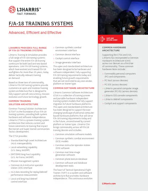
F/A-18 TRAINING SYSTEMS Advanced, Efficient and EffectiveL3HARRIS PROVIDES FULL RANGE OF F/A-18 TRAINING SYSTEMSL3Harris Training & Simulation provides a full range of F/A-18 training systems that support the entire F/A-18 training continuum for both land and sea-based operations. Link F/A-18 training systems, which have evolved and trained F/A-18 warfighters for more than 25 years, today deliver tactically relevant trainingon demand.Based on three tiers of commonality,L3Harris F/A-18 training systems provide customers an open and modular training system architecture that is designed to fully support aircraft concurrency, mission evolution and future technology growth. COMMON TRAININGSOLUTION ARCHITECTURE Common Training Solution Architecture (CTSA™) is the foundation of our F/A-18 training systems, providing both system hardware and software independence.L3Harris CTSA is a proven training system architecture that reduces current and future constraints to training that impact the Hornet and Super Hornet communities Tactics development.The CTSA provides:>Standardized High Level Architecture (HLA) interoperability>Local networking capability(U.S. Navy, NASMP)>DMT/DMO long-haul capability(U.S. Air Force, NASMP)>Mission management system>Common HLA instructor operator station (IOS) interface>HLA data recording for replay/debrief/ performance measurement>Local and long-haul debriefcontrol interface >Common synthetic combatenvironment interface>Common device interface>Cockpit control interface>Image generator interfaceThis open and standardized architecturehas been designed to be hardware andsoftware independent, fully supportingF/A-18 training requirements today andenabling future growth requirementsthat are not restricted to any one vendor,platform or trainer type.COMMON SOFTWARE ARCHITECTUREL3Harris Common Software Architecture(CSA) is a collection of training-provenand portable hardware independenttraining system models that fully supportmigration to future hardware platforms.This open and standardized architecturehas been designed to support the ever-changing landscape of personal computer-based hardware platforms that will serveF/A-18 training requirements today andin the future, unconstrained by currentplatform or trainer type. L3Harris CSAbrings commonality across all F/A-18training devices and includes:>Common simulation software models>Common synthetic combat environment(SCE) models>Common instructor operator station(IOS) software>Common real-time imagegeneration software>Common photo texture database>Common software and databasedevelopment toolsThe heart of Tactical Operational FlightTrainer (TOFT) is a system and softwarearchitecture that promotes hardwareindependence. The continuous evolutionCOMMON HARDWAREARCHITECTURESupporting the CTSA and CSA,L3Harris has incorporated a CommonHardware Architecture (CHA)across our devices as a third tierof commonality. These commonhardware items include:>Commodity personal computers(PC) and components>PC host (across devices)>PC IOS (across devices)>L3Harris personal computer imagegenerator (PC-IG) (across devices)>L3Harris IOS console components>L3Harris debrief components>Cockpit and support componentsinset image goes up hereCLICK in this RECTANGLE ANDTHEN GO TO FILE -> PLACE TOINSERT IMAGEof hardware platforms complicates simulator-to-aircraft configuration concurrency throughout the aircraft’s operational life.L3Harris maintains a common core of software that has been delivered on Gould, Encore, SGI and personal computer hardware platforms, including L3Harris SimuView® image generator. This focus on software commonality enables the leveraging of development efforts from various sources, including U.S. Navy, FMS and Link IR&D. Software commonality facilitates updates to all F/A-18 simulation devices—from Deployable Readiness Trainers (DRT) to TOFTs—with a single investment. TACTICAL OPERATIONAL FLIGHT TRAINERL3Harris SimuView® image generation system and scalable SimuSphere® visual display are combined to provide exceptional visual cueing realism necessary to support F-16 pilot training. SimuView employs off-the-shelf personal computer hardware and video cards, in addition to hardware independent image generation softweare. SimuSphere partial dodecahedron frame design—which is marked by seamless facet tolerances—allows for 3, 5, 7 or 9 display panels that provide pilots anywhere from 180 degree to 360 degree horizontal field of view.NIGHT VISION GOGGLE STIMULATIONOwning the night is key to successful F-16 air campaigns. L3Harris has developed a Night Vision Training System (NVTS) that provides night vision goggle (NVG) training as an integrated product solution. L3Harris NVTS couples the image generator, NVG sensor stimulation, head tracking, user-supplied NVG goggles and correlated databases into a single integrated system.DISTRIBUTED TRAINING NETWORKSL3Harris F/A-18 trainers are designed to support both local and wide area networking, enabling multiple simulators to participate in an exercise scenario. Depending on customer requirements, L3Harris also can provide a distributed briefing, mission observation and debriefing capability.INSTRUCTIONAL SYSTEMSA modern personal computer-based Instructor Operator Station (IOS) provides a workstation designed for efficient and effective training scenario execution. The IOS provides individual control over a single device or can control multiple devices in a distributed training environment.When combined with a scalable video wall consisting of plasma displays, the IOS becomes an integral part of a mission observation facility. The L3Harris IOS includes an entity station consisting of a stick, throttle and visual display.The heart of Tactical Operational Flight Trainer (TOFT) is a system and software architecture that promotes hardware independence. The continuous evolution of hardware platforms complicates simulator-to-aircraft configuration concurrency throughout the aircraft’s operational life.L3Harris maintains a common core of software that has been delivered on Gould, Encore, SGI and personal computer hardware platforms, including L3Harris SimuView® image generator. This focus on software commonality enables the leveraging of development efforts from various sources, including U.S. Navy, FMS and IR&D. Software commonality facilitates updates to all F/A-18 simulation devices—from Deployable Readiness Trainers (DRT) to TOFTs—with a single investment.TACTICAL OPERATIONAL FLIGHT TRAINERThe L3Harris TOFT, built and delivered for the F/A-18 Hornet and Super Hornet aircraft, has been designed to support the full Strike/Fighter training continuum. From Fleet Replacement Squadron (FRS) or basic flight through the most complex of tactical employment training, F/A-18 TOFTs deliver highly realistic simulations that can support singleship individual, multi-ship team and combat mission rehearsal training.F/A-18 TRAINING DEVICESThis open and standardized hardware architecture has been designed to beL3Harris-device independent, fully supporting F/A-18 training and minimizing logistics requirements today and in the future. Each of these tiers of commonalitysupport and reside across F/A-18 devices.The TOFT provides a training-proven solution for stand-alone, as well as local and long-haul networked training requirements, that provides an interoperable, scalable, full spectrum combat training environment. The TOFT is the first F/A-18 Defense Modeling and Simulation Office (DMSO) HLA-certified training device.The F/A-18 TOFT initially leveraged the L3HarrisHarris Link legacy F/A-18 WTT high-fidelity software to provide extensive procedural and weapons system training capabilities. The TOFT has evolved to a PC-based architecture, maximizing COTS and reuse. The PC-based TOFT, along with its modular software architecture, facilitates technology insertion and simulator/aircraft concurrency.The TOFT’s proven visual display systems, SimuSphere® and SimuSphere® HD, provide a very high-resolution, scalable field-of-view capability. With SimuSphere and SimuSphere HD, the TOFT footprint has been minimized, greatly reducing required facility size and power requirements. The modular TOFT can also be adapted as a deployable system for use in the field, on the road or aboard an aircraft carrier.Since the TOFT was designed with the tenets of modularity and scalability in mind, components can be tailored to exactly meet defined training and system requirements. These include unique avionics models, instructor and role player stations of varying fidelity and a brief/debrief system that allows students and instructors to fully reconstruct and manipulate an entire training event to maximize the effectiveness of the total learning experience.As a result, the F/A-18 TOFT presents the Hornet and Super Hornet Strike/Fighter a superior training environment, shaped in their requirements and founded on tactical relevance.TRAINING CAPABILITIESFor both U.S. and international employment, the TOFT supports all tactical and non-tactical training tasks associated with all variants of the F/A-18. When required, independent F/A-18 pilot and weapon sensor officer simulators that are networked can be surrounded by Link’s advanced 360 degree visual display systems. The TOFT provides proven high-fidelity crew station(s), displays, switches, validated aero, avionics systems and aircraft subsystems. Scalable TOFT SimuSphere visual system displays can provide up to a 360 degree field-of-view.Following are some of the missions and mission areas warfighters can train towards in the TOFT:>Individual or team training>Single-ship and multi-ship employment>Normal and emergency procedures>Basic air work, formation and local area operations>Instruments, navigation and all weather operations>Night vision goggle training and employment>Airfield takeoff and landings, carrier operations>Air-to-air and air-to-surface weapons training>Air-to-air and air-to-surface tactical employment training>High Off Bore Sight weapons employment training>Digital Close Air Support>Precision Target Acquisition training>Multi-functional Information Distribution>System (MIDS) training>Low altitude operations>Surface-to-air threat and counter tactics training>Mission rehearsalSCALABLE VISUAL DISPLAY TECHNOLOGYDelivering high performance imagery is the job of L3Harris’s patented SimuSphere and SimuSphere HD visual display systems. With excellent performance, seamless facet tolerances and flexibility, SimuSphere uses a dodecahedron frame design allowing for three, five, seven or nine display panels producing 180 degree to full 360 degree field-of-views.SimuSphere was the first small footprint system to produce constant resolution and brightness across all facets for a fully immersive visual experience.SimuSphere HD’s state-of-the-art digital projectors provides industry-leading sharpness and brightness. A fully integrated visual display, SimuSphere HD supports sharp, bright heads-up-displays; high-fidelity, physics-based stimulated night vision goggle capability; and is compatible with Helmet Mounted Cueing Systems and future visual/ sensor capabilities.EMULATED MISSION COMPUTER AND DISPLAYSL3Harris developed the first and only true emulation of the F/A-18 aircraft mission computers in 1998. This revolutionary software allows the aircraft operational flight program to be run directly by the simulator, in its native form, without preprocessing of any sort. The result is the highest fidelity cockpit presentation and facilitates ease of simulator concurrency with the aircraft at a greatly reduced cost.The combination of the mission computer emulation and faithful simulation of aircraft displays supports all aircraft operational display modes including:>Color digital map simulations>Full fidelity IR simulations>Correlated weapons video>Spatially correct HUD representation>Correlated A/A and A/G radar simulations>Distributed TrainingL3Harris has provided integrated F/A-18 training since 1983. In 2002, L3Harris achieved the first and only DMSO certification of HLA compliance on a four-ship of L3Harris F/A-18 simulators based at Naval Air Station Lemoore, Calif. Today, L3Harris F/A-18 devices are participating in multi-ship training exercises across the globe with various disparate training systems including air, land, and sea simulators.To assist in capturing the relevant training points of these complex, large scale exercises, L3Harris has a fully developed distributed briefing, mission observation and debriefing capability to round out the suite of services that provide F/A-18 operators with the most complete training system in the world.SYNTHETIC COMBAT ENVIRONMENTL3Harris open and modular CTSA supports the use of the best synthetic combat environment (SCE) or multiple SCEs, including commercial-off-the-shelf products for the training mission.There are many SCEs available on the commercial market that will continue to evolve over time, which is why L3Harris CTSA is designed to provide the flexibility and modularity needed to support future training requirements and technology growth. For stand-alone and networked training, L3Harris F/A-18 SCE provides the ideal tactical and natural environment to support the entire F/A-18 training continuum.L3Harris sophisticated F/A-18 SCE includes aircraft, missiles, ground vehicles, electronic warfare effects, weather and time-of-day controls. Performance and effectsof tactical threats and environmental effects are user definable and menu driven, enabling rapid integration of current threat, Order of Battle and environment information into the simulation.INSTRUCTOR OPERATOR STATIONThe new L3Harris F/A-18 IOS has been human factors and F/A-18 instructor-engineered to provide a workstation designed for efficient and effective training scenario execution. The F/A-18 IOS is a PC-based and HLA-connected component of L3Harris F/A-18 training systems.The IOS provides individual control over a single device, or can control multiple devices in a distributed training environment. The Microsoft Windows® -based L3Harris IOS provides the capability to initialize, support, control and monitor all aspects of a training exercise. When combined with a scalable video wall consisting of plasma displays, the IOS provides a state-of-the-art mission observation facility.DEPLOYABLE READINESS TRAINER The DRT can be thought of as arepackaged F/A-18 TOFT, providing reduced footprint and focused, tactically-relevant physical cockpit fidelity at a significantly reduced cost. The DRT uses the same computational system and software as the TOFT, so it provides the identical, accurate, high-fidelity OFP/SCS and systems replication provided by its higher physical fidelity relative.The system was designed to support deployed operations, with a fidelity focused on tactical employment and tactical procedures-based training associated with advanced training requirements.Using the same HLA architecture foundin the TOFT, L3Harris-built tactical task trainers can be fully integratedinto a distributed network to provide a fully interoperable force multiplier, friendly or hostile. The DRT has two visual systems. A flatpanel display can be used for a forward out-thewindow visual when a wide field-of-view is not needed.If a greater field-of-view or field-of-regard is required to support more complex and dynamic training, the L3Harris Fast Jet Helmet Mounted Display and night vision goggle solutions can provide a highfidelity, 360 degree visual environment for both day and night operations.t 817.619.2000 | f 817.619.3555 *****************This document consists of basic marketing information that is not defined as technical data under ITAR Part 120.10. Data, including specifications, contained within this document are summary in nature and subject to change at any time without notice at L3Harris Technologies’ discretion. Call for latest revision. All brand names and product names referenced are trademarks, registered trademarks, or trade names of their respective holders.L3Harris Technologies is an agile global aerospace and defense technology innovator, delivering end-to-end solutions that meet customers’ mission-critical needs. The company provides advanced defense and commercial technologies across air, land, sea, space and cyber domains.F/A-18 Training Systems© 2019 L3Harris Technologies, Inc. | 11/2019The L3Harris IOS also includes an entity station or instructor flown target (IFT) with a stick, throttle and visual display. With this component, instructors, operators or other event participants can take control over any threat aircraft or simulated blue aircraft to provide dynamic interactive control.Following are some of the roles this component can fill: >Lead for wingman training >Wingman for lead training >2-ship lead for 4-ship lead training >Tailoring threat air presentationThe entity station or IFT can be integrated with either an IOS stealth view, or it can be integrated with low-cost goggles providing a simple 360 degree field-of-view, to provide the entity pilot with a dynamic, interactive capability. DEBRIEFING SYSTEMThe L3Harris debrief system was born out of a cooperative effort between current and qualified FA-18 tactical aircrew, systems design engineers and training psychologists. The debrief system captures all mission event data. This data is stored and available for later use during mission analysis and debrief.To effectively present this information to maximize teaching and learning, L3Harris uses a state-of-the-art video wall. The L3Harris video wall is a scalable debrief system, comprised of multiple wall-mounted flat screen color displays and interactive whiteboard technology.These displays provide crew station display repeater function, a God’s-eye view of the mission replay over associated tactical maps or geographic terrain representations and a variety of images, including a stealth viewer, an event timeline, 3-D or 2-D displays and pair data displays that fully support multi-ship tactical debriefing.During a mission debrief, the mission commander may use the map to take the trainees through the planned mission prior to an event replay as well as annotating comments, flow and other points of interest using the interactive whiteboard technology. Central to the debrief system capability is the video playback system, integrated into the debrief event controls. Variable forward and reverse rates of playback speed are supported.In addition, the system captures and displays instructor-selected performance and execution data on an event timeline, as well as supporting manual event marking by an instructor or operator. In short, the debrief system provides the instructor and trainee alike a Strike/Fighter pilot-designed teaching and learning aid that will maximize the effectiveness of a training event.1025 W. NASA Boulevard Melbourne, FL 32919。
CMM/CMMI术语缩写一览表2008-09-11 16:55术语一览表(按字母排序)AB= Ability to perform (CMM KPA comon feature) AC=Activities to perform (CMM KPA comon featureAD/Software Group=Application DevelopmentAE=Adaptive Enterprise (HP) RTI AI=Assessment InstrumentAPW=Action Planning WorkshopARC=Appraisal Requirements for CMMIATQG=Aassessor Training and Qualifications Guide (ISO SPICE)ATW=Actiion Team WorkshopsBAM=Business Activity MonitoringBI=Business IntelligenceBpel=Business Process Execution LanguageBPFBPG=Baseline Practice Guide (ISO SPICE)BPM=Business Process ManagementBPM=Busiiness Process MaturityBPMM=Business Process Maturity ModeBPO=Business Process OutsourcingBPR=Business Process RedesignBSI=British Standards Institute (standard BS 15000) CAPM=Certified Associate in Project ManagementCAR=Causal Analysis and Resolution (CMMI process area)CBA=CMM-Based AssessmentCBA IPI=CMM-Based Assessment for Internal Process ImprovementCBP=Competency Based PracticesCCB=Configuration Control BoardC-CommerceCDG=Capability Determination Guide (ISO SPICE)CEP=Complex Event ProcessingCEU=Continuing Education UnitsCII=Confederation of Indian IndustriesCM=Configuration ManagementCMM=Capability Maturity Model (also referred to as SWCMM). A model for improving the capability of software organizations.CMMI=Capability Maturity Model-Integration (published by the Software engineering Institute at Carnegie Mellon University in Pittsburgh) /sei-home.html(integrates 3 source models the SW CMM, SE CMM and the IPD-CMM)CMU=Carnegie Mellon UniversityCO=Committement to perform (CMM KPA common feature)COBit=Control Objectives for Information and Related TechnologyCOCOMO II=COnstructive COst MOdel II is a model that allows one to estimate the cost, effort, and schedule when planning a new software development activity.CO=Commitment to PerformCOTS=Commercial off-the-shelfCPM=Corporate Permormance MonitoringCRADA=Cooperarive Research and Development AgreementCRD=Career Recommendations DevelopmentCRM=Customer Relationship ManagementDAR=Decision Analysis and Resolution (CMMI process area)DBA=Database AdministratorDELLTA=Danish Electronics Light & AcousticsDI=Directing ImplementationDoD=Department of DefenseDP=Defect Prevention (CMM Process area)DTIZC=Defense Technical Information CenterEAI=Enterprise Application IntegrationEDA=Event Driven ArchitectureEIA=Electronic Industries AllianceEIT=Enterprise Information IntegrationELG=Executive Leadership GroupEPG=Engineering Process GroupEPIG=Engineering Process Improvement GroupERP=Enterprise Resource PlanningESB=Enterprise Service BusesESP=External Service ProvidersETL=Extraction Transformation LoadingETVX format=Enty criteria, Tasks, Verification, and eXit criteria (CMMI)FAR=Functional Area Representative (term used in some assessments)FP=Function PointFTE=Full-time Equivalent (measure of personnel availability)GAO=General Accounting OfficeGESP=Global External Service ProvidersGG=Generic GoalGP=Generic PracticeG-Q-M Approach=Goal Queston Metric techniqueIC=Intergroup Coordination (CMM process Area)IDEAL=Initiating-Diagnosing-Establishing-Acting-Leveraging; an improvement cycle often used for process improvementIEC=International Electrotechnical CommissionIEEE=Institute of Electrical and Electronics Engineers.. A professional organizationIESP=Indian External Service ProvidersIG=Introductory Guide (ISO SPICE)IM=Integrated Management (CMM process area)IPD-CMM=Integrated Product Development Capability Maturity ModelIPM=Integrated Project Management (CMM process area)IPPD=Integrated Product and Process DevelopmentIPI=Internal Process ImprovementIPT=Integrated Product TeamISACA=Information Systems Audit and ControlAssociation ISM=Integrated Software Management (CMM process area)ISM=Integrated Supplier Management (CMMI process area)ISO=International Organization fro Standardization (International Standards Organization)IT=Integrated Teaming (CMM process area)ITIL=Information Technology Infrastructure LibraryJAD=Joint application designJIT=Just in TimeJTCI=Joint Technical Committee on Information TechnologyKGI=Key Goal IndicatorsKIPA=Korean IT Industry Promotion IndustryKP=Key practiceKPI's=Key Performance IndicatorKPA=Key Process AreaKSLOC=thousand source lines of codeMA (M&A)=Measurement and Analysis (CMM process area)MBNQA=Malcom Bridge National Quality AwardMDD=Method Description DocumentME=Measurement and Analysis (CMM KPA common feature)MOA=Memorandum of AgreementMOM=Message Orientated MiddlewareMQ=Maturity QuestionnaireMSG=Management Steering GroupMSMO=Microsoft Message Queue ServerMTBF-Mean Time Between FailuresOEI=Organizational Environment for Integration (CMMI process area)OID=Organizational Innovation and Deployment (CMMI process area)OO=Object OrientatedOOA&D=Object Orientated Analysis & DesignOoda=Observe-Orient-Decide-ActOPD=Organization Process Definition (CMM process area Level 3 KPA)OPF=Organizational Process Focus (CMM process area Level 3 KPA)OPF=Organizational Process Focus (CMMI process area)OPM3=Organizational Project Management Model (Published by PMI in January, 2004)OPP=Organizational Process Performance (OPF=Organizational Process Focus (CMMI process area)OSSP=Organization's Set of Standart PracticesOT=Organizational TrainingOPF=Organizational Process Focus (CMMI process area)OUSD/AT&L=Office of the Under Secretary of Defense, Acquisition , Technology and LogisticsPA=Process AreaPAIS=Process Appraisal Information Systems (Record of Entry Form for CBA IPIs)PAG=Process Assessment Guiide (ISO SPICE)PAT=Process Action TeamPC=Process Change (Management (CMM Level 5 KPA)PCA's=Pacaged Composite ApplicationsPCAR=People CMM Assessment Repository (Record of Entry Form for a PCMM Assessment)PCB's=Process Capability Baselines-a documented characterization of the range of expected resultsPCM=Process Change Management (CMM Level 5 KPA)PCMM=People Capability Maturity Model (CMM Level 3 KPA)PD=(Organization) Process DefinitionPDCA=Plan-Do-Check-Act; an improvement cycle often used for process improvementPDU=Professional Development UnitPE=(Software) Project Engineering (CMM Level 3 KPA)PF=(Organization) Process Focus (CMM Level 3 KPA)PI=Product IntegrationPII=Process Improvement IndicatorPII=Practice Implementation IndicatorsPIID=Practice Implementation Indicator Data (used for SCAMPI)PIG=Process Improvement Guide (ISO SPICE)PIP=Packaged Integration ProcessesPM=Project ManagementPMAT=appears in COCOMO II model shows the benefit of process maturity on and estimate of effort for a software project. CMM Level 2 to Level 3 noted improvements.4-11%PMBoK=Product Management Body of KnowledgePMC=Project Monitoring and Control (CMMI process area)PMC=Process Management CapabilityPMI=Project Management InstitutePMM=People Maturity ModelPMM=Process Maturity ModelPMP=Project Management ProfessionalPMO=Project Management OfficePP=(Software) Project Planning (CMM Level 2 KPA)PP=Project PlanningPI=Product Integration (CMMI process area)PPBs=Process Performance Baselines-a documented characterization of the actual results achieved by following a process.PPM=Process Performance Model (CMMI)PPQA=Process and Product Quality Assurance (CMMI process area)PSM= Practical Software and Systems ManagementPSM= Practical Software and Systems Measurement ()PSP/TSP=Personal Software Process/Team Software ProcessPT=(Software) Project Tracking (and Oversight) (CMM Level 2 KPA)PTO=Project Tracking and Oversight (CMM Level 2 KPA)QA=(Software) Quiality Assurance (CMM Level 2 KPA)QFD=Quality Function DeploymentQM=(Software) Quality Management (CMM Level 4 KPA)OO=Object OrientatedOoa&D=Object Orientation Analysis and DesignQP=Software Quality Process (Management (CMM Level 4 KPA) OPD=Organizational Process DefiinitionQPM=Quantitative Process Management (CMM process area) QPM=Quantitative Project Management (CMMI process area) RAI=Research Access Inc.RD=Requirements Development (CMMI process area)RE=Requirements EngineeringREQM=Requirements Management (CMMI process area)RM=Requirements Management (CMM Level 2 KPA)RM=Risk ManagmentROI=Return On InvestmentRPG=Report Program GeneratorRSKM=Risk Management (CMMI process area)RTE=Real Tme EnterpriseRTI=Real Time InfrastructureRTM=Requirements Traceability MatrixSA-CMM=Software Acquisition Capability Maturity Model SAM=Supplier Agreement Management (CMMI process area)Software Acquisition Management (CMM process area)SAP=Over the course of three decades, SAP has evolved from a small, regional enterprise into a world-class international company. Today, SAP is the global market leader incollaborative, inter-enterprise business solutions. The company now employs over 28,900 peopleSC7=Subcommittee 7 (ISO JTC1 subcommittee on software engineering)SCAMPI=Standard CMMI Appraisal Method for Process ImprovementSCCB=Software Configuration Control BoardSCE=Software Capability EvaluationsSCM=Software Configuration Management (CMM Level 2 KPA)SDD=Software Design DocumentSDF=Software Development FileSDLC=Software Development Life CycleSDP=Software Development Plan (also known as Project Plan)SE CAMM=Software Engineering Capability Assessment ModelSECM=Software Engineering Capability ModelSE CMM=Software Engineering Capability Maturity ModelSEI=Software Engineering Institute (at Carnegie Mellon University) 【软件工程学院】SEPG=Software Engineering Process GroupSEPI=Systems Engineering Process InitiativeSERP=Software Engineering Process GroupSG=Specific GoalSLA=Service Level AgreementSLOC=Source Line of CodeSM=Senior ManagementSM=(Software) Subcontract Management (CMM Level 2 KPA)SME=Subject Matter ExpertSOA=Service Orientated ArchitectureSOAP=Simple Object Access ProtocolSOW=Statement of WorkSP=Specific PracticeSPA=Software Process Assessment (SEI project; now CMM-based appraisals) software process assessment (method)SPC=Statistical Process ControlSPC=Software Product ConsortiumSPE=Software Product Engineering (CMM Level 3 KPA)SPI=Software Process ImprovementSPICE=Software Process Improvement and Capability DeterminationSPIN=Software Proess Improvement NetworkSPM=Software Process Mearurement (SEI project)SPP=Software Process Program; Software Project Planning (CMM Level 2 KPA)SPPT=Software Project Tracking and Oversight (CMM process area)SPTO=Software Project Tracking and OversightSQA=Software Quality Assurance (CMM Level 2 KPA)SQM=Software Quality Management (CMM Level 4 KPA)SRS=Software Requirements Specification (also known as RequirementsDocument)SS=Supplier SourcingSSM=Software Subcontract Management (CMM Level 2 KPA)STP=Straight Through ProcessingSW-CMM=Software Capability Maturity ModelTC176=Technical Committee 176 (ISO technical committee on quality managemetn systems)TCM=Technology Change ManagementTCO=Total Cost of OwnershipTM=Technology (Change) Management (CMM Level 5 KPA)TP=Training Program (CMM Level 3 KPA)TQM=Total Quality Management TQM can be defined as the application of quantitative methods and human resources to improve the materials and services provided asinputs to an organization an to improve all of the processes within the organization. The goal of TQM is to meet the needs of the customer, now and in the future.TS=Technical SolutionTTM=Time to MarketTTT=Train the TrainerTVO=Total Value of OpportunityUAN=Universal Application NetworkUAT=user Acceptance TestUDDI=Universal Desciption, Discovery and IntegrationVAL=Validation (CMMI process area)VB=Visual BasicVE=Verifying implementation (CMM KPA common feature)VER=Verification (CMMI process area)WBS=Work Breakdown StructureWG10=Working Group 10 (ISO/IEC JTC1/SC7 Working Group on software process assessment)WG7=Working Group 7 (ISO/IEC JTC1/SC7 Working Group on software life cycle processes)WiMAX=Worldwide Interoperability for Microwave Access. 802.11. 70MB Wireless connectivity over 30 milesWP=Workforce PlanningWS=Web ServicesWSDL=Web Services Descriptive LanguageXML=Extensible Markup LanguagexMM=Maturity Models for different business models (SW, I, P)XSL=Extensible Stylesheet LanguageZLE=Zero Latency Enterprise。
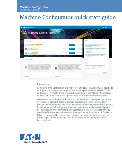
Machine Configurator quick start guideIntroductionEaton’s Machine Configurator is a Microsoft® Windows®-based software that helpsmanage Eaton configuration tools such as Power Xpert inControl, XSOFT-CODESYS,and Galileo. This guide provides instructions on how to use Machine Configuratorto install, uninstall, launch, and update these tools from your laptop/desktop.Cybersecurity is at the core of Eaton’s “secure by design” philosophy. Our securedevelopment approach helps us manage cybersecurity risks in our productsthrough the entire product life cycle—from threat modeling, requirements analysisimplementation and verification, to ongoing maintenance. Machine Configuratorhas been tested by an authorized UL® cybersecurity test lab, following industryestablished frameworks and standards. Eaton’s Cybersecurity Center of Excellence(CCoE) is committed to ensuring our customers are aware of the importance ofcontinuing to review, implement, and maintain recommended cybersecuritybest practices.Machine Configurator system requirements • Software: Microsoft Windows 10 or 11 (32-bit or 64-bit)• Screen resolution: 1280x1024 pixels or higher resolutionUser registrationBefore you can use and log into Machine Configurator, you need to be registered. Click Register Now! to begin. You will be re-directed to the Registration page. Follow the online instructions to complete your registration.Log inAfter you have completed registration, click Log in on the Machine Configurator window.On the Sign In page, enter your Username and click Next.Enter your Password and click Verify .To reset password:1. Click Change Password . The Reset Password windowwill open.2. Enter your email address and click Reset via Email .3. Follow the online instructions to change the password.Log outClick the user icon in the upper right side of the blue bar. Select Log outfrom the dropdown menu to exit the portal.2EATON Machine Configurator quick start guideMachine Configurator home pageMachine Configurator provides several features to manage different configuration tools(see screenshot below). Machine Configurator has three main sections:• Installed Apps• Available Apps• NewsInstalled AppsMachine Configurator will search for the applications installed on the laptop/desktop.After the search is complete, all installed applications and their respective versions will be displayed inthe Installed Apps section.N See Supported Applications on page 5 for more information about the Eaton applications.ote:In the Installed Apps window, you can launch or see additional information about that specific application.3EATON Machine Configurator quick start guideTo display information about the application before it is launched, select View More. Please refer to Product Specific Page on page 7 for more details.Choose the application you want to install and click Launch.If there are multiple versions of the application, select the version you want from the dropdown options and then click Launch.Available AppsApplications that are available to install and update are listed in Available Apps section. SelectLearn more to display additional information about the application. (See Product Specific Pageon page 7.)4EATON Machine Configurator quick start guideSupported applicationsMachine Configurator supports the following Eaton applications:Power Xpert inControlPower Xpert inControl device configuration and control software makes programming networked drives and soft starters quick and easy. It provides a processor-generic, simple interface for configuration, monitoring, troubleshooting, firmware gradation, and logic editing functionality using communication protocols. Power Xpert inControl software supports the latest version update. An older version on the laptop/desktop can be launched, uninstalled, or updated; however, multiple versions of Power Xpert inControl cannot be installed on the same laptop/desktop.On availability of the newest version of the application, Machine Configurator will show the details in the product specific page and update the available tag. For more information, please visit Eaton’s Power Xpert inControl configuration software webpage.XSOFT-CODESYSXSOFT-CODESYS software is the ideal programming tool for machine and process applications in machine building and system integration. The software is the perfect solution for all applications in which a powerful PLC or HMI-PLC with various field bus connections is required.XSOFT-CODESYS supports the installation of multiple software versions on the same system and all versions can be managed on the laptop/desktop. Machine Configurator supports the followingXSOFT-CODESYS versions:On availability of the application’s newest version, Machine Configurator will show the details in the product specific page and update the available tag. For more information, visit Eaton’s XSOFT-CODESYS programming software webpage.GalileoGalileo is an intuitive, easy-to-learn and powerful project design environment that fulfills almost all requirements of an on-site machine operation. With its non-sector specific concept, the visualization software offers seamless project design for allXV/XP operator panels and all PC run-time solutions. It providesfull functionality for the project designer at any time without any gradation restrictions on variables or screens.With only a few clicks, existing Galileo visualizations can be turned into web visualizations, which then enables remote/mobile operation as well.Galileo supports installing multiple versions on the same system and all versions can be managed on the laptop/desktop. MachineConfigurator supports the following Galileo versions:On availability of the application’s newest version, Machine Configurator will show the details in the product specific page and update the available tag. For product specific details, visit Eaton’s Galileo webpage.NewsThe News section lists all the latest updates from Eaton, including application updates and new releases.The Help section can be used for customer support information.5 EATON Machine Configurator quick start guideTo view All News, click View All.Click the news title to display the entire content.6EATON Machine Configurator quick start guideProduct specific pageThe product specific page displays the product details and the versions installed, and allowsthe user to download and uninstall the available versions on the system.If a new version is available and it is not installed on the system, antag is shown. Click Download to install the update.If you would like to install an older version, select an option from the Older versions dropdown menu.Machine Configurator’s product specific page also displays product Documentation, Tutorialand FAQs.The Documentation section provides resources and product support that can be downloaded and therequired links to useful information to assist the user in effectively operating and using the application.The Tutorial section lists tutorials, learning videos and other instructional aids to help the user becomemore proficient with the application.The FAQs section provides the user with quick and easy access to helpful information and the answersto the most relevent questions.7EATON Machine Configurator quick start guideEaton is a registered trademark.All other trademarks are property of their respective owners.Eaton1000 Eaton Boulevard Cleveland, OH 44122United States ©2024 EatonAll Rights Reserved Printed in USAPublication No. MN040080EN / Z29177August 2024SettingsMachine Configurator offers three system settings to enhance user experience.Minimize to System Tray: When this setting is turned on, the application will continue to run in the background instead of closing completely. You can relaunch the application by using the system tray icon.Language: This setting allows you to choose the preferred language of the tool. Once you select the desired language, all the text and various elements will be displayed in that specific language.All languages other than English are sample texts and are marked as BETA. Valid translations for respective languages will be provided in future updates and the BETA tag will be removed.Update Machine Configurator Automatically: This setting enables the Machine Configurator application to be updated automatically when the latest version becomes available. This new version will be downloaded and updated whenever the application is restarted.To reach an EatonCare representative, please call:+1-877-ETN-CARE or +1-877-386-2273 (USA)+1-800-268-3578 (Canada)+1-828-651-0786 (International)Follow us on social media to get thelatest product and support information.。
<Placeholder cover – we will adjust> Microsoft Azure StackLicensing Guide(end customers)August 20173 3 6 6 8How Azure Stack is purchasedThere are two ways to purchase Azure Stack:1.Purchase Azure Stack services via your own EA2.Purchase Azure Stack services from a service providerThis document provides licensing guidance for running the Azure Stack within your own enterprise. If you purchase Azure Stack services from a service provider, the provider will set the pricing and terms of use and offer support.Azure Stack is sold as an integrated system, meaning that software comes installed on prescribed hardware. A complete Azure Stack system is comprised of hardware, software, and support.Hardware: Hardware is purchased directly from the hardware vendor. A complete list of Azure Stack hardware partners can be found on the Azure Stack product page. If you are purchasing Azure Stack from a service provider, you may not need to purchase your own hardware.Software: You may purchase Azure Stack services via your Microsoft Enterprise Agreement (EA) or from a service provider. This document describes the model for purchasing Azure Stack via Microsoft EA only. When purchasing Azure Stack from a service provider, the service provider will set the terms and prices for the services.Support: If you purchase Azure Stack services from a service provider, your provider will provide support. If you purchase Azure Stack services via your Microsoft EA, support comes in two parts—hardware support and software support.•Hardware support is contracted directly with the hardware partners.•Software support is contracted directly with Microsoft. If you already have software support from Microsoft (Azure or Premier support plans), those contracts cover Azure Stack softwaresupport and no additional contracts or fees are needed. While support is with the hardwarepartner and Microsoft, our integrated support experience provides coordinated escalation and resolution, so you get a consistent support experience no matter who you call first. Azure Stack software–packaging and pricingThere are three layers to Azure Stack software: the cloud infrastructure that powers the system, the services running on the system, and portal capabilities. Only services running on the Azure Stack are billed. Services can be licensed in one of two ways as shown in Table 1--a pay-as-you-use (consumption-based) model and a capacity model.Table 1: Licensing ModelsPay-as-you-useThe pay-as-you-use model has no up-front fees and you pay only when you use a service, as shown in Table 2. This model offers a continuous transaction experience with Azure. Usage for each service is metered and transmitted to Microsoft Azure commerce, where the information is integrated and billed with your Azure usage.There is no initial deployment fee for pay-as-you use. Additionally, you are not charged for the virtual machines and software required to power the Azure Stack infrastructure. This means that Cloud Infrastructure, Management, Security, and Identity Services, as well as Networking and Service Fabric are not charged. The following describes the units of metering for the services available on Azure Stack at general availability. All services are entirely stand-alone. For example, when you run App Service, you are only spinning App Service meters.Table 2. Azure Stack Pay-as-You-Use Metering UnitsUp-Front Licensing Azure Stack initial deployment n/a – no upfront feesConsumption-Based Fees Cloud infrastructure; Management, Security, andIdentity; Networking; Service Fabricn/a – includedVirtual Machines: Base VM $/VCPU/minVirtual Machines: with Windows Server $/VCPU/minBlog Storage Service $/GB (no transaction fee) Tables and Queues Service $/GB (no transaction fee) Azure App Service $/VCPU/minTo run Windows Server virtual machines, you have the option of either using the native meters within Azure Stack or deploying existing Windows Server licenses in conjunction with the Azure Stack Base VM hourly meters. To run SQL Server virtual machines, you may deploy existing licenses in conjunction with Windows virtual machines. Details for how existing licenses work in conjunction with Azure Stack can be found in the “Using existing software” section of this document.Azure Stack pay-as-you-use services are available in EA and are sold in the same way as Azure services. This means Azure Stack is acquired via a monetary commit SKU on your Azure or SCE enrollment. You can use the same agreement, pool of monetary commit, and subscription IDs for your Azure and Azure Stack services. If you have an existing Azure agreement, you don’t need any additional agreemen ts or monetary commitment purchases—you need only enter your subscription ID when you install the system. Your Azure Stack usage will be metered and integrated into one bill with your Azure usage.Capacity ModelThe capacity model offers a more traditional licensing model for disconnected scenarios, as shown in Table 3. An annual subscription fee licenses all the physical cores on your Azure Stack. The capacity model is available in an App Service package or an IaaS package. The App Service package includes all the services on the IaaS package, plus Azure App Service (including Web, Mobile, Logic Apps, and Functions).Table 3. Azure Stack Capacity Model—Licensing Packages$/physical core/year$/physical core/yearAzure App ServiceAzure StorageBase Virtual MachineWindows VirtualBYO License BYO LicenseMachineSQL Server VirtualBYO License BYO LicenseMachineYou need existing Windows Server or SQL Server licenses to run Windows Server and SQL Server virtual machines on the capacity model. Details on how existing licensing works in conjunction with Azure Stack are discussed in “Using existing software” section of this document.The capacity model is available in EA only and can be ordered via standard Volume Licensing channels. The capacity model will not have integrated billing with Azure and Azure monetary commitment cannot be applied to the capacity model.Azure Stack supportAzure Stack support is a consistent, integrated, hybrid support experience that covers the full system lifecycle. To fully support your Azure Stack system, you need two support instruments—one with Microsoft for cloud services support and one with your hardware provider for system support. Our integrated support experience provides coordinated escalation and resolution, so you get a consistent support experience no matter who you call first. If you already have Premier, Azure, or Partner support with Microsoft, your Azure Stack software support is included.Although support is purchased in separate components, Microsoft and the hardware providers have partnered to create a unified support experience. You need only make one call to the vendor of your choice (Microsoft or hardware partner) for any Azure Stack issue. That vendor will help you diagnose the source of the issue and route your question accordingly.Using existing software with Azure StackCustomers may use existing software licenses (e.g., Windows Server, SQL Server, Marketplace services) in conjunction with Azure Stack. Azure Stack is treated like on-premises hardware for purposes oflicensing existing software. Customers must comply with all product licensing terms under which the software is acquired. When other software is used in conjunction with Azure Stack, the fee structure is:Licensing fees for the software (paid to the software vendor) + virtual machines consumed to run the serviceGuidelines for how Microsoft Windows Server and SQL Server licensing are applied to Azure Stack systems are discussed in the following sections.Windows Server licensingWhen deploying Windows Server virtual machines on Azure Stack, you may use existing Windows Server licenses as an alternative to the native hourly Windows Server meters in the pay-as-you-use model. Windows Server licenses acquired apart from Azure Stack are subject to terms and conditions stated in the Microsoft Product Terms.What follows are some guidelines for how the licensing terms and conditions can be applied when existing Window Server licenses are used with Azure Stack:1.Number of licenses required for Windows Server used with Azure StackTo comply with Windows Server licensing, all cores in an Azure Stack region must be covered, just like when licensing Hyper-V. Furthermore, all cores must be covered with the same edition of license (all Datacenter or all Standard), since the virtual machine may be sitting anywhere on the Azure Stack. We recommend Windows Server Datacenter for Azure Stack, since weanticipate your workloads will be heavily virtualized. You can use EA, Open, or Select PlusWindows Server licenses. Customers using volume licensing licenses must also have sufficientCALs to cover the use case. Since Azure Stack is on your own hardware, you do not need Azure Hybrid Use Benefit (AHUB) rights to use Windows Server in conjunction with Azure Stack.2.AHUB with Azure StackAzure Stack is considered on-premises hardware for licensing purposes. As such, you do notneed AHUB to use existing Windows Server licenses in conjunction with dedicated Azure Stack environments. Furthermore, the AHUB benefit does not extend to bringing Windows Server EA licenses to hosted, multi-tenant environments; you may not bring Windows Server EA licenses to such environments.SQL Server licensingSQL Server virtual machines can be deployed on Azure Stack by using separately acquired SQL Server licenses in conjunction with Windows virtual machines. SQL Server licenses acquired outside Azure Stack are subject to Microsoft Product Terms.What follows are some guidelines that illustrate how licensing terms and conditions are applied when existing SQL Server licenses are used with Azure Stack:1.Number of core licenses required for SQL Server used with Azure StackSQL Server may be licensed either by physical cores or by virtual machines. If licensing byphysical cores, you must license the entire Azure Stack region1. If licensing by virtual machines, you only need enough licenses to cover the virtual machines using SQL Server (subject to aminimum of 4 per virtual machine). If licensing by virtual machines, you may separately allocate SQL Server Enterprise and Standard edition licenses by virtual machine. Since Azure Stack is the customer’s own hardware, you do not need License Mobility when using SQL Server under EA on your own Azure Stack hardware.2.License MobilityAzure Stack is considered on-premises hardware for licensing purposes. As such, you do notneed License Mobility to use SQL Server licenses in dedicated Azure Stack environments. You will, however, need License Mobility if you bring your own SQL Server EA licenses to a service provider’s multi-tenant hosted environment. In that situation, you must also ensure your service provider is an authorized License Mobility provider.Example scenariosThe following figures and text illustrate a few examples for how services are licensed on Azure Stack, particularly focused on contrasting the licensing for pure Azure Stack meters with scenarios where on-premises licenses are used in conjunction with Azure Stack.If using all native meters, as in Figure 1, you pay only for what you use. Usage is metered on a per minute basis. Storage is decoupled from virtual-machine instances and paid for separately.Figure 1. All Native Azure Stack MetersWhen you use existing licenses to deploy Windows Server virtual machines on Azure Stack, you bring your own license and pay only a consumption rate on Base VM meters. You must have enough Windows Server core licenses to cover the entire Azure Stack region, regardless of how many Windows Server virtual machines are deployed on the Azure Stack. In the scenario shown in Figure 2, 25 of the 75 virtual machine cores (vcores) are using Windows Server. However, since there are 100 physical cores in the system, 100 Windows Server core licenses are needed. When used with existing Windows Server licenses, Azure Stack only runs consumption meters at the Base VM rate for the Windows Server virtual machines.Figure 2. On-Premises License with Azure StackWhen using existing licenses to deploy SQL Server virtual machines on Azure Stack, you pay for those SQL Server licenses, plus Windows virtual machines. In Figure 2, since we’ve already deployed enough separately acquired Windows Server licenses to cover the entire Azure Stack region, only a Base VM fee is metered for the 25 vcores being used for SQL Server virtual machines. If you are only using SQL Server for part of your deployment, you may license it on a per-virtual machine basis. In accordance with SQL Server licensing rules, there is a 4-core licensing minimum per virtual machine. Even if you deploy a 1-node SQL Server virtual machine, you must still pay for and allocate 4 core licenses. DefinitionsAzure Stack region: A region is a logical concept describing a set of physical resources to which workloads can be assigned. The Azure Stack ARM may assign a workload deployed to an Azure Stack region to any of the physical resources within the region. Administrators will configure the boundaries of the region, but regions will have a minimum of 4 physical nodes to ensure redundancy. (At general availability, Azure Stack will support only one region per deployment.)。
第一章软件过程基础(10分)1、几位软件质量管理大师的主要贡献休哈特:* 统计质量控制之父* 提出计划-执行-检查(Plan-Do-See)戴明:* 质量改进* PDCA Plan-Do-Check-Action* 十四点原则朱兰:* 质量控制手册(Quality Control Handbook)* 适用性质量* 质量三部曲* Juran质量螺旋(Quality Loop)* 80/20原则克劳比士:* 零缺陷* 质量管理的绝对性* 质量改进的基本要素哈弗雷Watts Humphrey:* 提出CMM理论* 将TQM的思想用到软件过程改进* 力推个体软件过程和团队软件过程2、经典软件过程及其特点* Rational统一过程(RUP)* 敏捷过程-极限编程(XP)* Scrum* SPICE第二章PSP(30分)1、PSP中的基本度量项* 时间* 缺陷* 规模2、PROBE估算的基本流程* 概要设计* 代理项识别* 估算并调整程序规模(时间)* 计算预测区间3、使用线性回归方法估算软件规模和资源计算规模* plan size = β0 + β1(E)* n>=3, β0 and β1:β1 = (∑x(i)y(i))-(nx(avg)y(avg))/(∑x(i)^2)-(nx(avg)^2)β0 = y(av g) - β1*x(avg)计算时间* plan time = β1 + β1(E)* n>=3, β0 and β1:β1 = (∑x(i)y(i))-(nx(avg)y(avg))/(∑x(i)^2)-(nx(avg)^2)β0 = y(avg) - β1*x(avg)计算预测区间略4、相对大小矩阵σ: 平方差简单方法正态分布法对数正态分布法(对数据取自然对数InX)VS: 最小值M-2σe^(avg-2σ)S: (VS+M)/2 M-σ e^(avg-σ)M: 中值avg e^(avg)L: (VL+M)/2 M+σ e^(avg+2σ)VL: 最大值M+2σe^(avg+σ)5、常用的PSP过程质量的指标YieldPhase Yield = 100*(某阶段发现缺陷数)/(某阶段注入缺陷数+前阶段遗留缺陷数)Process Yield = 100*(第一次编译前发现的缺陷数)/(第一次编译前注入的缺陷数)A/FR(质检失效比)A/FR = PSP质检成本/PSP失效成本* PSP质检成本:设计评审和代码评审时间之和。
Data SheetFujitsu PRAID EP400i / EP420iRAID Controller SAS 12Gbit/s 1GB or 2GB cache based on LSI MegaRAID® for internal storage devices The RAID architecture (Redundant Array of Independent Disks) combines multiple storage devices, including hard drives and NVMe devices, into a single logical unit. Redundancy data is generated from data segments (barring RAID 0) and distributed across the devices. Consequently, operating systems interact with this collective array rather than the individual devices. The core purpose of RAID is to enhance data availability, reducing potential disruptions from storage devices failures. The effectiveness of a RAID setup largely depends on the RAID controller in use.Choose Fujitsu RAID controllers for a blend of modern technology and proven experience,providing the data protection that businesses need today.PRAID EP400i / EP420iThe Fujitsu RAID ControllerPRAID EP400i with 8ports sets new speed and data security standards for internal storage drives. The RAID stack isbased on the LSI MegaRAID® and offers high data throughput, a comprehensive fault tolerancefunction and user-friendly management options.Moreover, the Controller management is integrated seamlessly into the Fujitsu server managementconcept. All controller functions are supported by the Fujitsu ServerView RAID Manager. The PRAIDEP400i is designed for backward compatibility with 3Gbit/s SAS as well as with 6Gbit/s and 3Gbit/sSATA hard drives. Regardless of the drive speed, itdelivers significant performance improvements in both read and write applications. Due to the support of 64-bit addressing, a robust set of RAID features and demanding error tolerance functions the controller provides high RAID performance and data availability. Powerful online management service programs (Fujitsu ServerView RAIDManager), which are simple to operate and quick to install, provide the administrator with unparalleled flexibility and access to the arrays. The RAIDcontroller supports all of the important RAID levels including RAID 6 and 60. The optional flash battery backup (FBU) combined with TFM module ensures the integrity of the data stored in the cache on the RAID controller in case of a power outage. In this event, the data will be copied to a non-volatile flash memory (TFM). The FBU provides a low-priced alternative to an uninterruptible power supply (UPS) and, when compared to battery backup up units (BBU), enables a long-term, secure store ofdata and better serviceability. Always select FBU and TFM module in combination.The Advanced Software Options in combination with Solid State Disks in front of HDD volumes can create high-capacity,high-performance controllercache pools, depending on the load profile. A free of charge test version is available at PRIMERGY-PM.Link: /dl.aspx?id=c816a64f-8b6d-47df-ba31-836874f08c07Technical detailsTechnical detailsController Silicon RoC (RAID on Chip) LSI SAS3108Adapter Type RAID 5/6 Ctrl.Operating system pre-installed Information to released operating systems can be found in the server datasheets. Details can be found in thereleased drivers list on the support portal.Released drivers list link /Download/Index.aspNumber of ports8 ports int.Connector internal2x SFF8643 (Mini-SAS HD)Data transfer rate up to12 Gbit/sBus type PCIe 3.0Bus width x8RAID Management ServerView RAID ManagerStorCLI (command-line interface)BIOS Configuration UtilityKey RAID Data Protection Feature- RAID levels 0, 1, 5 and 6- RAID spans 10, 50 and 60- Maximum number of spans is 8- Online Capacity Expansion (OCE)- Online RAID level Migration (RLM)- Auto resume after loss of system power during array rebuild or reconstruction (RLM)- Fast initialization for quick array setup- Single controller multipathing (failover)- Load Balancing- Configurable stripe size up to 1MB- Fast initialisation for quick array setup- Check consistency for background data integrity - Make Data Consistent (MDC)- Patrol read for media scanning and repairing- Up to 64 logical drives per controller- S.M.A.R.T support- Global and dedicated Hot Spare with Revertible Hot Spare support- Automatic rebuild- Enclosure affinity- Enclosure management- SES (inband)- SGPIO (outband)RAID level0, 1, 10, 5, 50, 6, 60RAID cache backup unit Optional FBURAID controller notes based on LSI SAS3108Interface technology SAS/SATAOrder code Product Name Height of bracket RAID controller cache size Number of Connectors S26361-F5243-E11PRAID EP400i Matching to system 1 GB2S26361-F5243-E12PRAID EP420i Matching to system 2 GB2S26361-F5243-E14PRAID EP420i for SafeStore Matching to system 2 GB2S26361-F5243-L11PRAID EP400i Full Height / Low Profile 1 GB2S26361-F5243-L12PRAID EP420i Full Height / Low Profile 2 GB2S26361-F5243-L14PRAID EP420i for SafeStore Full Height / Low Profile 2 GB2S26361-F5243-L1PRAID EP400i Full Height / Low Profile 1 GB2S26361-F5243-L2PRAID EP420i Full Height / Low Profile 2 GB2S26361-F5243-L4PRAID EP420i for SafeStore Full Height / Low Profile 2 GB2Order code Product Name NotesS26361-F5243-E100PRAID EP400i TFM installed - Transportable Flash Module - contains flash memoryand control logic for Flash Backup Unit (FBU) – required for FBUoptionS26361-F5243-E200TFM PRAID EP420i/e installed - Transportable Flash Module - contains flash memoryand control logic for Flash Backup Unit (FBU) – required for FBUoptionS26361-F5243-E125RAID Ctrl FBU option for PRAID EP4xx with 25cm cable installed - Super-capacitor incl. cableinstalled - Super-capacitor incl. cableS26361-F5243-L110RAID Ctrl FBU option for PRAID EP4xx with 25cm, 55cm, 70cmcableComplianceCompliance notes According to the corresponding systemCompliance link https:///sites/certificatesContactFujitsu LimitedWebsite: /primergy2023-11-27 WW-ENworldwide project for reducing burdens on the environment.Using our global know-how, we aim to contribute to the creation of a sustainable environment for future generations through IT.Please find further information at http://www./global/about/environmenttechnical specification with the maximum selection of components for the named system and not the detailed scope ofdelivery. The scope of delivery is defined by the selection of components at the time of ordering. The product was developed for normal business use.Technical data is subject to modification and delivery subject to availability. Any liability that the data and illustrations are complete, actual or correct is excluded. Designations may be trademarks and/or copyrights of the respective owner, the use of which by third parties for their own purposes may infringe the rights of such owner.More informationAll rights reserved, including intellectual property rights. Designations may be trademarks and/or copyrights of therespective owner, the use of which by third parties for their own purposes may infringe the rights of such owner. For further information see https:///global/about/resources/terms/ Copyright 2023 Fujitsu LIMITED。
Home Contact UsAdvanced SearchProducts Motherboards Pentium® 4 Boards [ P4SCE ]Key Features1. Intel® Pentium® 4 Support up to 3.4 GHz,Celeron® up to2.4 GHz2. Intel® E7210 (Canterwood ES) Chipset3. Up to 4GB DDR 400/333/266 SDRAM4. 2 x Intel® 82541 Gigabit Ethernet Controllers5. Serial ATA Controller on-chip (Intel®ICH5R)6. 5 x 32-bit 33 MHz PCI (5V)7. ATI RageXL 8MB PCI Graphic ControllerLinks & ResourcesRecommended Chassis Tested Memory List Motherboard Manual Update Your BIOS Download the Latest Drivers and UtilitiesPhysical Stats Form Factor ATXDimensions 12" x 9.5", (30.5cm x 24.1cm)Processor/CacheCPU• Single mPGA478 ZIF Sockets• Supports an Intel® Pentium® 4 processor with 2MB of integrated Advanced Transfer Cache up to 3.4GHz (Extreme Edition)• Supports an Intel® Pentium® 4 processor with 1MB of integrated Advanced Transfer Cache up to 3.2GHz• Supports an Intel® Celeron® processor with 128KB of integrated Advanced Transfer Cache up to 2.4GHz• Hyper-threading enabledSystem Bus 800 / 533 / 400MHz system busSystem Memory Memory Capacity• Four 184-pin DIMM sockets• Supports up to 4 GB of DDR400/333/266memory• Dual channel memory bus• Memory must be populated in pairs Memory Type DDR400/333/266 (ECC or non-ECC)unbuffered SDRAM, 184-pin gold-plated DIMMs DIMM Sizes 256 MB, 512 MB, 1 GB Memory Voltage2.5 V onlyOn-Board Devices Chipset• Intel® E7210 (Canterwood ES) chipset • MCH + ICH5R + FWHChassis ( Optimized for P4SCE )1U Chassis • SC811-IDEP4RackmountTower / 4U • SC742i-300Mid-Tower • SC733i-300Tower • SC762-420Important Note To ensure system stability, a 300W (minimum)ATX power supply [4-pin +12V AND (20 or24-pin)] is required.System BIOS BIOS Type4Mb Flash EEPROM with AwardBIOS®BIOS Features• Plug and Play (PnP)• APM 1.2• DMI 2.3 support • PCI 2.3• ACPI 1.0• BIOS rescue hot keys• Hardware BIOS virus protection • USB Keyboard supportManagement Software• Super Doctor III • Watch DogPowerConfigurations• ACPI/APM Power Management • Main Switch Override Mechanism • Wake-On-Ring (WOR) header • Wake-On-LAN (WOL) header • Suspend to RAM (STR)• Power-on mode control for AC power loss recovery• Internal/External modem remote ring-onPC Health MonitoringP4SCESearchSerial ATA • SATA Controller on-chip (Intel® ICH5R)• Dual Serial ATA ports • RAID 0, 1 Supported *Network Controllers • Dual Intel® 82541 Gigabit Ethernet• Supports 10BASE-T, 100BASE-TX, and 1000BASE-T, RJ45 outputGraphics ATI Rage XL SVGA PCI video controller with 8MB of video memoryInput / Output PCI Expansion • 5x 32-bit 33MHz PCI (5V) slotsIDE• Dual EIDE channels support up to four UDMA IDE devices• Supports UDMA Mode 5, PIO Mode 4, and ATA/100USB Up to 8 USB ports Infrared 1 Infrared port headerSerial Ports 2 Fast UART 16550 serial ports Parallel Port 1 ECP / EEP Parallel PortFloppy 1 Floppy controller; 1.44 MB, 2.88 MB, 3-mode supportKeyboard /MousePS/2 keyboard and mouse ports* - Driver Support for Windows 2000, XP, and 2003 onlyCPU• Monitors for CPU Cores, +3.3V, +5, ±12V,+3.3V/+5V Standby, VBAT• CPU Core 3-Phase-switching voltageregulator with auto-sense from 0.85V-1.65V • Adjustable CPU clock frequency ratio settings (via BIOS)FAN• Total of four 3-pin fan headers • 3x fans with tachometer monitoring• Status monitor with firmware/software on/off controlTemperature• Monitoring for CPU, chassis, environment • CPU thermal trip support LED• CPU Overheat LED • System Overheat LED • +5V standby alert LED• Suspend-state indicator LED Other Features • Chassis intrusion detection • Chassis intrusion headerOS Compatibility• Please see our OS Compatibility ChartStandard Retail PackagePart NumberQty Description P4SCE MBD-P4SCE-O 1P4SCE Motherboard Manual(s)MNL-06971Manual for P4SCERetention KitsSKT-1091Pentium 4, 478 Pin CPU Retention Module I/O CablesCBL-010CBL-022CBL-036CBL-041CBL-044111129-pin Serial Port Cable ATX Floppy CableATA 66/100 IDE LP CableUSB 2.0 4-Port Cable with Key on 102 Ft. Amphenol Serial ATA Cable Driver Disk CDR-INTC 1Version 1.00 Chipset Driver CD I/O ShieldCSE-PT71I/O Shield for Dual LANNote: Items in a Standard Retail Package may differ from items in a Standard Bulk Package.Terms & Conditions | Privacy | Investor Relations Copyright © 2009 Super Micro Computer, Inc.Information in this document is subject to change without notice.Other products and companies referred to herein are trademarks or registered trademarks of their respective companies or mark holders.Page Viewed: Tuesday, January 13, 2009: @09:54:37。
SMALL 4 AXIS STEPPER MOTOR CONTROLLER MODULEWITH G-CODE INTERPRETATORDATASHEET2021-02-07, Rev. #72SCE22OVERVIEWOverviewSCE2-M is a fully integrated stepper motor controller module for digital control for limited space applications. Designed for small 3D printers, laser cutters/engravers, CNC mills, pick and place machines, robots, test fixtures, and other motorized devices. SCE2-M module is the smallest motor controller that requires no external components and runs industry-standard g-code processor with linear interpolation control open-source firmwareSystem On Module (SOM) design Fully integrated, ready to use4 stepper motors drivers, up to 1/256 microstepping 4 Limit switch inputs Direct connect USB portOptional TTL USART/I2C ports 8 IO ports (some with hardware PWM output capability)32bits ARM-Cortex M3 microcontroller, running at 72Mhz Advanced motor control with T rinamic driversDigital current control of stepper motor drivers directly from g-codeFeatures• • • • • • • • • 3FEATURESPinoutSCE2-M module has some STM32 pins routed to external pads. Pads grouped by functionality provided in tables below.GPIO pin mapping tableIO pin CPU port Function CPU features1PB1SPINDLE ENABLE ADC2PB9PROBE I2C SDA3PA8PWM OUTPUT4PB4FLOOD5PB3MIST6PB0SPINDLE DIR ADC7PB5STOP8PB8 I2C SCL PA8 (PWM OUTPUT) is set to 10kHz frequency, but can be adjusted in firmware. Limit switch mapping tablePort Net namePB12LIMIT1PB13LIMIT2PB14LIMIT3PB15LIMIT4PA9LIMIT_ENUART pin mapping tableCPU port Net namePB7USART1_RXPB6USART1_TXSchematic symbolDimensions and footprint Mechanical dimensionsComponent footprint3D STEP file is maintained on Github8FIRMWARE FirmwareOpen source STM32F103 GRBL firmware is maintained on GithubBy default firmware can be uploaded with STLINK over exposed SWD pins.STM32F103supports flashing over USB port,but in latest release it is still notsupportedStock firmware registers as "STM32 Virtual COM". Most modern operating systems should work out of the box, but original drivers can be downloaded from STMicroelectronics web pageFirmware is con figured to work at 115200 8N1 baud rateFeel free to use favorite terminal program. For further demonstration will use T erminal AppCommunication over USBDriversCOM portT erminal programIn some Windows cases Prolific USB to serial controller drivers can claim detected COM port, in this case uninstall driver and install downloaded from ST web page.Assume axis has proper configuration sent earlier, making moves is as easy as entering commandIn terminal bottom field type G0 X10 and press EnterIf linear actuator is connected it should move at default max speed by 10mm (rotary actuator should turn 10deg).In order to move at different speeds G1 command should be used. For exampleG1 Y10 F100List of supported G-code commands:G0, G1: Linear MotionsG2, G3: Arc and Helical Motions G4: DwellG10 L2, G10 L20: Set Work Coordinate O ffsets G17, G18, G19: Plane Selection G20, G21: UnitsG28, G30: Go to Pre-De fined Position G28.1, G30.1: Set Pre-De fined Position G38.2: ProbingG38.3, G38.4, G38.5: ProbingG40: Cutter Radius Compensation Modes OFF (Only)G43.1, G49: Dynamic T ool Length O ffsets G53: Move in Absolute CoordinatesG54, G55, G56, G57, G58, G59: Work Coordinate Systems G61: Path Control Modes G80: Motion Mode Cancel G90, G91: Distance Modes G91.1: Arc IJK Distance Modes G92: Coordinate O ffsetG92.1: Clear Coordinate System O ffsets G93, G94: Feedrate ModesQuick start guideFirst motor moves• • • • • • • • • • • • • • • • • • • • •G100, G101: TMC2300 register read/write M0, M2, M30: Program Pause and End M3, M4, M5: Spindle Control M7* , M8, M9: Coolant Control M56* : Parking Motion Override ControlIn order for controller to function correctly pulse count per revolution, acceleration and optionally motion limits has to be specified. In order to read configuration type $$ and press Enter .All internal con figuration parameters will be printed out. For example:• • • • • Controller is shipped with X axis configured for RSB1 and X axis configured for LSA1(0.635mm version)Con figurationRecommended values for LSA1 actuator and RSB1 actuatorRead con figuration parameters$0=6$1=255$2=0$3=31$4=1$5=0$6=0$10=19$11=0.010$12=0.002$13=0$20=0$21=0$22=1$23=15$24=50.000$25=200.000$26=250$27=5.000$30=1000$31=0$32=0$100=111.110$101=1007.874$102=17.778$103=1536.000$110=20000.000$111=2500.000$112=500000.000$113=20000.000$120=2000.000$121=300.000$122=40000.000$123=1000.000$130=360.000$131=90.000$132=360.000$133=360.000Detailed explanation can be found on GRBL documentationWrite configuration parametersWriting specific value is as easy as typing $100=1000 and pressing Enter If number is valid, this command will overwrite existing value and save to EEPROM.Control softwareThere are number of software packages suited to control CNC machines. Comprehensive list is maintained by GRBL developers on GitHub. Our favorite is Candle by DenviSome g-code examples and recipesG-code while being universal machine control language has various flavors and capabilities. Below section is dedicated to speed up manual machine control with simple commands.Move motorsThere are two basic linear motion commands G0 and G1. Both are generally the same just G0 uses default max speed constant from configuration. Examples (assume linear actuator is connected):Command ExplanationG0 X100Move X axis to absolute position 100mmG1 X0 F100Move X axis to 0 position at speed 100mm/minControl GPIO pinsGRBL is designed for CNC machines and IO pins are used to make sense. Pin description is provided here, but for actual functionality source code should be inspected.Command ExplanationM7MIST = ONM8FLOOD = ONM9MIST = OFF, FLOOD = OFFCommand ExplanationM3Set clockwise spindle rotationS300Set spindle control pin PWM duty cycle at 30% (max S = 1000)M4Set counter clockwise spindle rotationM5T urn spindle offMotor homingAfter powering controller on it does not know motor position, thus it should be driven to home reference positionCommand Explanation$HX Initialize X axisAlmost any time controller status can be read with command . It will report motor status (Idle/Run), actual positions and some other info.Functionality between versions will vary, some firmware versions or branches can have special functionality .Firmware allows use of touch trigger probes. Moves down Z axis and stops on when probe pin is triggered, then reports collision point.Idle command is useful for certain operations where controller needs to wait and do nothing (for example wait till spindle speeds up).Read controller statusCommandOutput<Idle|MPos:0.000,90.000,0.000,0.000|Bf:35,254|FS:0,0>Read firmware version stringCommandOutput$I[VER:1.1f-SCE2.20200405:][OPT:VMZHL,35,254]okProbingCommandExplanation and OutputG38.2 F100 Z-100Move down Z axis until PROBE pin is triggered F - SpeedZ - T arget depthReplies with [PRB:1.503,0.000,-22.860,0.000:1]• • Idle / waitCommandExplanationG4 P60000Wait 1 minute, reply with ok when doneFirmware has implemented functionality to read and write individual T rinamic TMC2300registers over internal UART single wire interface. It shares transmit and receive line like an RS485 based interface. Data transmission is secured using a cyclic redundancy check and each TMC2300 driver is addressed individually as follows:Write register command forwards g-command arguments to TMC2300 configuration interface. While it is not recommended because of stability issues, write command can be sent even if motors are turning (G0, G1, ... commands)Reading and writing TMC2300 registersAxis AddressX 0Y 1Z 2A3Broadcast to all axes9O fficial TMC2300 documentationAll numbers in g-code arguments are decimal base numbersWrite registers7'th bit of TMC2300 register has to be set to 1, thus for example 0x10 IHOLD_IRUN becomes 0x90G100P <xx>L <xx>N <xx>S <xx>F <xx>R <xx>G-commandTMC2300addressTMC2300register(mask with 0x80)DATA3DATA2DATA1DATA0Read registers command has two arguments TMC2300 address and register address. It responds to terminal immediately .Response is decimal coded 12 bytes. Sample reply looks like this: [TMC:5,0,16,112,5,255,16,0,0,0,0,157]Required checksum is calculated in firmwareRead registersG101P <xx>R <xx>G-commandTMC2300 addressTMC2300 registerReply byte Meaning0Echo transmit byte01Echo transmit byte02Echo transmit byte03Echo transmit byte04Reply from TMC2300 sync (0x05)5Address 6Register 7Data byte38Data byte29Data byte110Data byte011ChecksumEach motor driver can drive different motor. Power and other settings can be set individually .For example IHOLD_IRUN (0x10) register controls motor idle, run and timing parameters.G100 P0 L144 N0 S0 F10 R5ExamplesSet motor X currentG100Write to TMC2300 g-command P0Driver address = 0 (X axis)L144TMC2300 register IHOLD_IRUN (0x10)0x10 ->(set 7'th bit to 1)-> 0x90 = 144 (dec)N0Data3 = 0 (not used)S0Data2 = 0 (see IHOLDDELAY in table below)F10Data1 = 10 (see IRUN in table below)R5Data0 = 5 (see IHOLD in table below)Each TMC2300 driver has input status registers GSTAT (0x01) indicating over temperature,short circuit, and more.G101 P0 R1Response looks like:[TMC:5,0,1,193,5,255,1,0,0,0,1,154]Response contains only 3 bits of useful information. See explanation in table below .Read input register21READING AND WRITING TMC2300 REGISTERSAutomating tasksPython g-code senderAutomating tasks can be done with Python script.Below is script example to send commands provided in text file:import timeimport osfrom tqdm import tqdmimport serialimport argparseparser = argparse.ArgumentParser()parser.add_argument('-p','--port', help='COM port', required=True)parser.add_argument('-f','--file', help='File name', required=True)args = parser.parse_args()ser = serial.Serial()ser.port = str(args.port)ser.baudrate = 115200ser.timeout = 10ser.open()ser.flushInput()ser.flushOutput()print("Reading file...")lines = []with open(args.file) as fp:for cnt, line in enumerate(fp):lines.append(line)print("Sleeping 1s...")time.sleep(1)for line in tqdm(lines):l = bytes(line.strip()+ '\n', 'utf8')ser.write(l)grbl_out = ser.readline()T ext file example:G91M7M8G1 X45 F20000M9G1 X45 F20000M8G1 X45 F20000M9G1 X45 F20000M8G1 X45 F20000M9G1 X45 F20000M8G1 X45 F20000M9G1 X45 F20000G90SCE2-BREAKOUT demo boardSCE2-BREAKOUT is a fully integrated stepper motor controller module carrier board for quick SCE2-M module evaluation. Designed for small 3D printers, laser cutters/engravers, CNC mills, pick and place machines, robots, test fixtures, and other motorized devices. SCE2-M module is the smallest motor controller that requires no external components and runs industry-standard g-code processor with linear interpolation control open-source firmware.SchematicsP9 is breaks power supply from USB port. Should be disconnected if power is applied via P8 headerP10 bridges 5V and VM. Should be disconnected if VM is applied via P8 Dimensions3D STEP file is maintained on GithubSCE2_dual_L012 dual lens controller boardSCE2_dual_L012 is a fully integrated stepper motor controller module carrier board for controlling two motorized lens zoom/focus parameters. Controller requires only 5V power supply from the USB port and controlled with text-based G-code commands over USB or optionally TTL UART.Controller is shipped with default settings as listed below .SchematicsMotor wiring vs axis de finitionAxisMotor function Connector XFocus J1YZoom J1ZFocus J2A Zoom J2Controlling the lensesRecommended GRBL settings$0=6$1=255$2=0$3=31$4=1$5=0$6=0$10=19$11=0.010$12=0.002$13=0$20=0$21=0$22=1$23=15$24=50.000$25=200.000$26=250$27=5.000$30=1000$31=0$32=0$100=111.110$101=111.110$102=111.110$103=111.110$110=50000.000$111=50000.000$112=50000.000$113=50000.000$120=5000.000$121=5000.000$122=5000.000$123=5000.000$130=360.000$131=360.000$132=360.000$133=360.000$N0=G100P9L144N0S0F1R1Startup sequenceDefault TMC2300 power is too high for small stepper motors and will overheat and damage them. Motor drive/sleep current has to be decreased with commands listed below:G100 P0 L144 N0 S0 F1 R1G100 P1 L144 N0 S0 F1 R1G100 P2 L144 N0 S0 F1 R1G100 P3 L144 N0 S0 F1 R1Or in a single command (valid since 20200103 firmware update)G100 P9 L144 N0 S0 F1 R1Which then can be added in GRBL startup sequence $N0=G100P9L144N0S0F1R1Homing sequenceLenses have no limit switches, thus precision homing is not possible. Instead each motor is driven to max position until hard stop and it is assumed that home position is achieved.G91 # set motion to relative coordinate systemF30000 # set default motion speedG1 X-500G1 Y-1200G1 Z-500G1 A-1200G90 # set motion to absolute coordinate systemG92 X0 Y0 Z0 A0 # set current position as 0Control sequenceIf power settings are reduced in startup stage, lens motors can be operated right away. Standard G-code motion commands can be used to drive motors. For example:G1 Y100 A100 F40000G1 Y-100 A100 F40000G1 Y100 A-100 F40000G1 Y-100 A-100 F10000DimensionsMounting hole diameter is (not indicated) in drawing is 2.3mm3D STEP file is maintained on GithubALL PRODUCTS, PRODUCT SPECIFICATIONS,AND DATA ARE SUBJECT TO CHANGE WITHOUT NOTICE TO IMPROVE RELIABILITY, FUNCTION OR DESIGN OR OTHERWISEKurokesu UAB, its affiliates, agents, and employees, and all persons acting on its or their behalf (collectively, "Kurokesu"), disclaim any and all liability for any errors,inaccuracies or incompleteness contained in any datasheet or any other disclosurerelating to any product.The Information given herein is believed to be accurate and reliable. However, users should independently evaluate the suitability of and test each product selected fortheir applicationsSee Kurokesu standard terms and conditions for warranty and other informationDo not short circuit any part of the moduleDo not exceed nominal inputDo not overload outputsKeep the module dryObserve the electrostatic discharge (ESD) precautions when handling the product.Damage caused by non-observance of the above instructions is not covered by thewarrantyPower electronics equipped with thermal shutdown circuitry, but if controller becomes too hot disconnect itModule is designed exclusively for installation into a device or housing to prevent external in fluences such as humidity/water or dirtAdd active and/or passive power filtering circuitry in an electromagnetically noisy environment if a module becomes unstableAdd active and/or passive power filtering circuitry if module exceeds allowed EMC emissionsPrecautions and disclaimersGeneral disclaimer• • • • Precautions• • • • • • • • • 33PRECAUTIONS AND DISCLAIMERS。
SCE: A Fully Integrated Software Tool for Beowulf Cluster SystemPutchong Uthayopas, Thara Angskun, Somsak Sriprayoonskul, and Sugree PhatanapheromParallel Research Group, CONSYLDepartment of Computer Engineering, Faculty of Engineering Kasetsart University, Bangkok, ThailandAbstractOne of the problems with the wide adoption of clusters for mainstream high performance computing is the difficulty in building and managing the system. There are many efforts in solving this problem by building fully automated, integrated software distribution from several open source software. However, these sets of software come from many sources and never been designed to work together as a truly integrated system. So, some problem is still remaining unsolved.With the experiences and tools developed to build many clusters on our site, we decided to build an integrate software tool that is easy to use for cluster user community. This software tool, called SCE (Scalable Computing Environment), consists of a cluster builder tool, complex system management tool (SCMS), scalable real-time monitoring, web base monitoring software (KCAP), parallel Unix command, and batch scheduler (SQMS). This software run on top of our cluster middleware that provides cluster wide process control and many services. MPICH are also included. SCE are truly integrated since our group builds all tool but MPICH. SCE also provides more than 30 APIs to access system resources information, control remote process execution, ensemble management and more. These APIs and the interaction among software components allow user to extends and enhance SCE in many ways. To make things easy, the installation and configuration in SCE are fully automated completely by GUI. This paper will discuss the current SCE design, implementation, and experiences. SCE is expected to be available as a developer version in June.1 IntroductionBeowulf Cluster [1] has been accepted as a platform that creates a great deal of impact in a HPC area. The reason is that Beowulf cluster bring extremely high computing power to scientists and engineers at a very low cost. As a result, the use of this platform rapidly increases during the last few years. Nevertheless, building and operating a Beowulf cluster requires many expertises. The problem is more severe as the system size grows. To address this problem, many research groups [2][3] have built many tools that help reduce the complexity of building and maintaining Beowulf clusters.Recently, there are many packages such as SCYLD [4] and Oscar[5] that attempt to provide an integrated cluster distribution that includes all necessary tools in one package. Nevertheless, there are still some problems left unsolved. First, the configuration of each tool is still separated. Second, these tools usually start many components with duplicated functions. This is inefficient and wastes a lot of system resources. By building a fully integrated cluster environment, all these problems can be eliminated totally.In this paper, SCE a fully integrated software tool for Beowulf cluster is introduced. SCE consist of a set of tools includes cluster builder tools, system management tool, real-time monitoring system, cluster middleware, batch scheduler, parallel Unix command and much more. These tools are building by the same research group and hence, the integration of these tools are considered since the beginning. Therefore, the installation and operation of SCE are very easy for users and system administrators.The remainder of this paper is organized as follows. Section 2 explains some of the important term used. Section 3 gives an overview of SCE, follows by the description of SCE installation process in Section 4. Section 5 briefly describes the functionality of cluster builder tool called Beowulf Builder. Section 6 discusses about SCMS cluster management tool follows by the discussion of SQMS, batch-scheduling system in SCE. Section 8 presents the current status of SCE. Finally, Section 9 presents the conclusion and future work.2 TerminologyIn this section, the terms used through out this paper are defined. First, this paper assumes that standard cluster system consists of one or more master node and many of the slave nodes. This master node responsible for the management of the system and also act as a centralize file server for small cluster. Slave node is a complete computer that usually used to perform the computation. Slave node can be either diskless node or disk full node. For diskless node, the operating system and root file system is totally stored on master node. Although diskless node can have a local disk, this local disk is used for data storage and swap space only. In contrast, diskfull nodes use local storage as a boot device that store completeoperating system image. All operating system start up can and will be done locally. Master and slave nodes are connected through one or more interconnection network. This network is primarily used for message passing in parallel programming.3 Overview of SCESCE consists of a set of feature rich software environment that allows users to easily build and maintain cluster configuration, monitoring various performance parameters, schedule sequential and parallel job. As shown in Figure 1, SCE consists of 4 main components. First, Beowulf builder is a software tools that create cluster and maintain cluster configuration. User use Beowulf Builder to automatically create all necessary configurations that allows a set of diskless nodes to remotely boot from master node. Once user finishes the installation, a middleware layer called KSIX [6] controls normal operations of a cluster. KSIX always run in background and provides many services to upper layer software tools. There are 2 main software systems running on top of KSIX, that is SCMS [7] cluster management system and SQMS batch scheduling system. SCE also include MPICH [8][9], one of the most widely use MPI implementation so user can start programming in parallel under SCE immediately after the installation finish. In the following section, each part of the system will be explained in more detail.Figure 1: SCE ArchitectureThe clear advantage of SCE approach in integrating all cluster software tools together are as follows.• Reducing the needs to do a complicated setup of multiple tools and keep the global configuration consistent.• Sharing of software components make the system smaller, consume less system resources, and works faster.• Software component interact better since they are design from the beginning to work together. For instance, batch scheduler can usemiddle service for process control and use performance-monitoringservices to do a better resources management.4 SCEInstallationA typical cluster configuration that SCE expect to see is as shown in Figure 2. SCE assume that a Beowulf cluster system consists of one or more master node and many slave node that connected through IP network. For users, SCE comes in 2 formats: A downloadable tar/gzip format or CD ready ISO file format. Once unpacked, a directory will be created. This directory will be referred in a subsequent explanation and SCE home directory.Figure 2: Typical SCE based Beowulf cluster system ArrayFigure 3: SCE Installation processSCE installation begins by running file name setup found in SCE home directory. This operation start a component of SCE called SCE Master Installer. Main function of SCE master installer is to install the rest of SCE packages and additional library using rpm tool. The installation process is shown in Figure 3.Basically, each SCE tool can be divided into 3 parts: Install Wizard that helps configure the tool initially, Tools Body which is the real working part of the tools, and Uninstall Wizard that do the cleanup. Therefore, in SCE, one can easily added more tools with only a minor modification in SCE master Installer. In addition, users will have an option of de-installation of a particular tool of required. During the installation, SCE master will run in the background and automate the invocation of each tool’s wizard. The goal of SCE installation is to allow users to finish the installation process up to the point that MPICH can run without typing anything. This is possible by defining a good defaults and using a standard cluster platform.Figure 4: Screen shots of SCE 1.0 (Alpha version) Installation5 Building Cluster with Beowulf BuilderTwo major approaches are used to remotely installed slave nodes. LUI [10] software from IBM enables users to remotely boot slave node first, then use rpm command to remotely install RPM based packages are later. VA System Imager[11] uses a different approach by having user install a complete slave node called golden slave first. Then, there are utilities that help user grab the configuration to centralize server and push it to multiple slave node.In SCE, a tool called Beowulf Builder is built for the same purpose. The installation process of Beowulf builder use a little of previously described approaches. Basically, SCE assume that user must install the master node first, then run Beowulf builder later. Once running, Beowulf builder will have a wizard that get basic configuration information from users about slave nodes. The screen shot of Beowulf Builder Wizard is as illustrated in Figure 5.Figure 5: Screen Short of Beowulf Builder WizardAfter the configuration, Beowulf builder automatically extracts required system files and library to build root file system and /usr file system for each diskless slave node in /tftpboot. User have can use Beowulf builder to generate a boot floppy or binary image for NIC boot prompt. The easiest way to boot slave node is to insert this so-called “magic boot floppy” into floppy disk drive of slave node and power on that node. The boot process start automatically using combination of DHCP, TFTP based remote boot protocol. After slave node has been started, it will use NFS root file system and /usr file system on server. This approach makes the installation very automatic and work well for small cluster to about 100 nodes clusters//// SCE Cluster Building Process//main(){Install Linux RedHat Package;SCEInstaller();}void SCEInstaller(){InstallKSIXrpm(); InstallSCMSrpm();InstallKCAPrpm(); InstallSQMSrpm();InstallExternalPackage();// now we have packages in place on master nodeConfigandBuildCluster();KSIXWizard(); SCMSWizard();SQMSWizard();// OK We are readyRebootMaster();forallslave {BootSlavenode();}}void InstallExternalPackage(){InstallPIL(); // Python Image LibraryInstallLibprg(); // our own component}void ConfigandBuildCluster(){GetUserDefineNodeSetParameter();Loopcreatconfigure();bootmedia=GetBootMediaFromuser();Switch(bootmedia) {case Bootrom : Createbootromimage();break;case Floppy : CreateBootFloppy();break;case CDROM : CreateBootCDROM(); // not support yetbreak;case FLASH : CreateBootFlashImage(); // not support yet break;}}void BootSlaveNode(){SlavesendDHCP(); GetDHCPreply();LoadKernelbyTFTP(); BootKernel();MountNFSroot(); NormalBoot();}Figure 6: Beowulf Builder Boot ProcessProcess of building a cluster are as shown by pseudocode in Figure 6. Besides using Beowulf builder to install cluster, user can later use this software to customize cluster configuration as well. Web interface has been partly supported but not complete yet.5.1 KSIX Cluster MiddlewareKSIX is user level software, no kernel modification are required to run KSIX. This feature allows for easy installation and high portability. KSIX is start by a bootstrapping utility called kxboot and stop with a utility called kxhalt. After KSIX are loaded, applications enroll into KSIX environment by calling a function cpi_init() (CPI comes from Cluster Programming Interface). In the following subsection, services offered by KSIX are explained.5.2 Global Process SpaceKSIX application can use KSIX to spawn a new task, which is distributed among nodes in the cluster. KSIX uses an automatic scheduling policy to select the target nodes. The policy module is open to the modification in the future. KSIX also allocates a set of global process ID and process group for these tasks. The id is used for task identification in the subsequent call. There are 3 modes of task supported.• Normal Mode: Task acts the same as a normal Unix task.• Restart Mode: KSIX will automatically restart this task on the same node when task terminated.• Migration Mode: KSIX start the task on different node when task termination is detected.KSIX process control APIs support the sending of UNIX signal, getting process information and more. These APIs are summarized in Table 1.5.3 Naming ServicesIn KSIX, processes can locate each other through naming service. The naming service APIs are as shown in table 2. With this service, a server process can register to a logical service name. Then, client process can bind with server using this logical services name. This allows the service server to be restarted or migrated to other node without any disruption of the service. Using this feature, we has built a feature called Fault-Tolerance RPC as shown in table 3. This feature can be used to link between stateless server and client and provides a basic level of high-availability.Table 1: KSIX Process Management APIs.API Description int cpi_spawn( char *task, int flag, char *where, int ntask, int*tid, int *gid, int pclass)Spawning tasksint cpi_spawnIO( char *task, int flag, char *where, int ntask, int *tid, int *gid, char *output, char *error, int pclass)Spawning tasks with specific location of outputint cpi_waitpid(int pid, int *status, int timeout) Wait for process terminationint cpi_setpmode(int pid, int mode) Change class of processint cpi_setgmode(int gid, int mode) Change class group of processint cpi_pkill(int pid, int signal) Send signal to process int cpi_gkill(int gid, int signal) Send signal to processint cpi_allps(KxProcStat *result) Report process status of all processint cpi_userps(KxProcStat *result) Report process status of user processTable 2: Naming Services APIs.API Descriptionint cpi_ds_reg(int, char *, struct servinfo, int *) Register server with naming serviceint cpi_ds_unreg(int, char *, int, int) Unregister server with naming serviceint cpi_ds_getinfo(int, char * ,struct servinfo, structreturninfo **)Query information of serverint cpi_ds_free(struct returninfo *) Free dynamic memoryTable 3:Fault Tolerant RPC APIs.API DescriptionKxFD *cpi_FRPC_cinit(char *service_name) Initialize clientKxFD *cpi_FRPC_sinit(char *service_name) Initialize serverKxFD *cpi_FRPC_accept(KxFD *cpifd) Accept a connection on a socket void cpi_FRPC_close(KxFD *cpifd) Close a socket descriptorint cpi_FRPC_send(KxFD *cpifd, void *buf, int size) Send a messageint cpi_FRPC_recv(KxFD *cpifd, void *buf, int size) Receive a message size5.4 Event ServicesDistributed event notification and delivery is crucial part for the implementation of many high level services including High Availability services. KSIX alsosupport event delivering between processes. Process can bind itself to named event. As the event is invoked or trigged by any process on any node. KSIX will reliably deliver the notification to the registered event owner. The APIs are as shown in table 4Table 4: Event Services APIs.API Descriptionint cpi_em_reg ( int, void *, struct servinfo, int *)Register event handlerint cpi_em_unreg ( int, void *, int, int ) Unregister event handlerint cpi_em_raise ( int, char *, struct servinfo, char*, int, struct answer **, int )Raise eventint cpi_em_read ( int *, char *, int, int *, struct timeval ) Event handler read message from event manager or raw TCP/IPint cpi_em_write ( int, char *, int ) Event handler write message to event manager5.5 Ensemble ManagementFor large cluster, system software, tools and application must be acknowledge about the change in cluster topology. KSIX subsystem that responsible for this task are called ensemble management. KSIX delete mal-function node from the ensemble automatically system it has been detected. KSIX also automatic add a new node to ensemble after the bootup process. The APIs for this class of service are illustrated in table 5.Table 5: Ensemble Management APIs.API Descriptionint cpi_addhost(char *hostname) Add host to KSIX systemint cpi_delhost(char *hostname) Delete host from KSIX systemint cpi_gethostbyrank(int rank, char *result) Convert rank to hostnameint *cpi_getrankbyhost(char *hostname) Convert hostname to rankint cpi_getallhost(KxHostInfo *hostinfo) Get array of hostname sort by rankThe following subsection gives some ideas about the application of KSIX in improving cluster environment. This support will be added in SCE in the near feature.5.6 KSIX Support for Scalable Unix ToolsIn cluster environment, the capability to issues a command to execute on every node and collect the results back is very important. User usually rely on rsh and ssh mechanism for remote command execution. But these command lack thefeature of collective operations. Hence, the execution is slow and not very scalable for large system. There is an effort to define a parallel extension to Unix command by parallel tool consortium. This SUT (Scalable Unix Tools)[12] effort is well explained in the literature. Currently, our tool, SCMS support an implementation of SUT in a form of shell script that rely on rsh for remote execution. Using KSIX fast and collective process management, a powerful SUT implementation can be done by replacing rsh with KSIX based remote execution command. Remote process can be started simultaneously on the remote machines to execute local Unix command. Then KXIO can be used to relay back the result efficiently.5.7 KSIX Support for MPI2 ImplementationKSIX dynamic process management are designed such that process creation, process termination, process group, and signal delivery can be extended to support dynamic process management of MPI-2 standard with ease. MPI_COMM_SPAWN can be mapped to KSIX spawn. Process in KSIX always form into a group or context, this can easily be mapped to context-based concept of communicator in MPI. Parent and child group can be create by first create KSIX group, then using KX_Spawn to create child group. Group id and intercommunicator can be build and keep track later. Finally, efficient dynamic process creation and control provided by KSIX can be mapped directly to MPI2 approach and help ease the development effort greatly.6 SCMS Cluster Management SystemSCMS is a main tool that will be seen in SCE. SCMS is divided into 2 layers as illustrated in Figure 7.Figure 7 SCMS ArchitectureSCMS lower layer is a set of daemon subsystems and utilities written in C, C++, and Python script language. This layer consists of:• Scalable Unix tool: A parallel implementation of frequently used Unix commands that follows the guideline given by Parallel Tool Consortium.•SCMS/KCAP Script which is a set of script written mostly in Python and Shell script. These scripts help perform many administrative task in the system. • SCMS/RMS, a fast, scalable real-time monitoring and a set of powerfulAPI in C, C++, Java, and Python that user can use to develop monitoringapplication. These API are as shown in Table 6 and Table 2.Table 6: RMI API for C language RMI API Descriptionint rmi_init(char *addr,int port); Establish the connectionint rmi_finalize(int sd);Close connection int rmi_get_node(int sd,rmi_node_struct *nodes, int max); Retrieve node name and nodeid of all alive nodesint rmi_get_nodeid(int sd,rmi_int_struct *hid); Retrieve node id of all alivenodesint rmi_get_async(int sd,rmi_int_struct *hid, rmi_int_struct *pid,char *opt, char *buf,int max); Retrieve objects in particularnodes to the buffer using asynchronous modeint rmi_get_sync(int sd,rmi_int_struct *hid, rmi_int_struct *pid,char *opt, char *buf,int max); Retrieve objects in particularsnodes to the buffer usingsynchronous nodeint rmi_set(int sd,rmi_int_struct *hid, char *key,char *value); Set internal variable "key" to"value"int rmi_load_plugin(int sd,rmi_int_struct *hid, char *plugin);Load plugin on specified nodeint rmi_unload_plugin(int sd,rmi_int_struct *hid, char *plugin); Unload plugin on specified nodeint rmi_int_init(rmi_int_struct *lst,int max); Allocate resource vectorint rmi_int_finalize(rmi_int_struct *lst); Free resource vectorint rmi_int_add(rmi_int_struct *lst,int i); Add to resource vectorint rmi_int_pack(rmi_int_struct *lst,char *buf, int max);Pack list of integer to a stringThe upper layer of SCMS consists of 2 main tools. SCMS and KCAP. SCMS is a GUI application based on Python and Tkinter. SCMS enable user to navigate, manage, monitor, and control the operation of Beowulf cluster from a single point. Some unique features of SCMS are:• Interface to SCMS/RMS real-time monitoring• Cluster Configuration collector and browser• Control command that allows system administrator to shutdown, rebootany node or set of nodes.• Innovative user interface in 3D grid format that allows user tomanipulate thousands node cluster.Some of the screen shot from SCMS are illustrated in Figure 7.Figure 8: SCMS Screenshot showing (a) Host Selector (b) Real-time Monitoring (c) Heart Beat Checking (d) Configuration BrowserSCE also offers a web base monitoring package called KCAP that allows system administrator to check monitor system remotely,. Many most of the monitoring function appears in SCMS also available in KCAP as well. Also, KCAP can help keep log of system performance, and perform cluster walk-in visualization using VRML and java based technology. Examples of KCAP user interface and cluster visualization are as shown in Figure 9.Figure 9: KCAP Screen shot showing the main menu, file system , 3D visualization of cluster nodes and file system in one node7 SQMS Batch schedulingOne of the most important components in cluster software tool is a batch scheduler. Batch scheduler received user request for program execution, select optimum set of nodes, sending a job to run, and finally, collect the result back. There are many well-known batch schedulers such as OpenPBS [13], DQS [14]. Although very powerful, these schedulers are usually very complex to install, use, and maintain. SCE try to solve this problem by giving the scientists a simple but workable scheduler called SQMS. For more intricate requirement, user can also install more complicated scheduler such as OpenPBS for their use.High-light of some features offered by SQMS are:• Support both sequential and MPI based parallel program• Provides command line to submit job, query queue status, and delete jobs.• Move result into user home file system• Support multiple form of reporting result such as email and ICQ users.• Round robin, node• Allows users to add new task scheduler• Provides C/C++ API for user to develop complex load balancing policy if required.Figure 10: SQMS Screen Shot (a)listing the queue (b) result reportedthrough mail or ICQThese functions are enough to allow multiple users to submit jobs to the system. For more detail features comparison, please refer to Table 3. From Table 3, it seems that SQMS have much less feature than OpenPBS. This is due to the focus of the development that aims more toward the integration of software in this version. Moreover, the emphasis is to develop a simple and easy to use batch scheduler. So, many of OpenPBS features are ignore since it increase a learning time of the user and, in many cases, some of these features are hardly used.8 Current Status of SCECurrent version of SCE, SCE alpha 1.0, is now available for early download at http://smile.cpe.ku.ac.th/sce . This version of SCE is intended to be a test version that developers can gain and early experience and feedback to SCE developmentteam. Beowulf Builder is still not fully function since there is an ongoing work on a new version of builder tool that is much more powerful. According to the internal schedule, SCE 1.0 Beta1, which is more stable, will be released in June.9 Conclusion and Future DirectionIn this paper, SCE, a fully integrated Software Tool for Beowulf cluster has been partly described. SCE is a rapidly evolving and long-term project. The goal is to deliver a simple but high quality cluster environment for engineers and scientists who use Beowulf cluster to do their work. Many software in SCE is the results of more than 5 years of our software tool research effort.SCE is a very active and long-term research program. There are many works that is being done now to improve SCE. First, SQMS team is now working quickly on improving SQMS in many ways. The focus will be on better support of parallel task, better scheduler, and more supporting tool that enhance system usability. Moreover, There is a new project called SCENIC (SCE on Network of Interconnected Clusters) that is investigating the addition of grid like capability so that all SCE based cluster to exchange computational task seamlessly.For KSIX, there are many related projects to enhance its capability. For example, AMATA project that is now exploring the High availability support in middleware layer, SCK project currently produce kernel level checkpointing so KSIX2 which is due next year will start to partially have checkpointing support and process migration. Better integration with MPICH will be added into SCE. There is now a work on using KSIX, KXIO, and SCMS/RMS to build a debugger and runtime visualization software for MPICH. Finally, more services and tools will be added in the next releases to enhance the usability and power of SCE.10 AcknowledgementSCE project is sponsored by Kasetsart University Research and Development SRU Grant, Faculty of Engineering, Kasetsart University Grant. Many types of equipment and Athlon based cluster system used are sponsored by AMD Far East Inc.References[1] T. Sterling, D. J. Becker, D. Savarese, J. E. Dorband, U. A. Ranawake, and C.E. Packer, “Beowulf: A Parallel Workstation for Scientific Computation”, in Proceedings of International Conference on Parallel Processing 95,1995[2] SMILE Project, Parallel Research Group, http://smile.cpe.ku.ac.th[3] R. Flanery, A. Geist, B. Luethke, and S. Scott, "Cluster Command & Control (C3) Tools Suite", /~sscott/[4] SCYLD Beowulf, SCYLD Computing Corporation, /page/products/beowulf/[5]OSCAR Linux distribution, Open Cluster Group, /oscar/[6] Thara Angskun, Putchong Uthayopas, Choopan Ratanpocha, “KSIX parallel programming environment for Beowulf Cluster”, Technical Session Cluster Computing Technologies, Environments and Applications (CC-TEA), International Conference on Parallel and Distributed Proceeding Techniques and Applications 2000 (PDPTA’2000), Las Vegas, Nevada, USA, June 2000[7] Putchong Uthayopas, Jullawadee Maneesilp, Paricha Ingongnam, “SCMS: An Integrated Cluster Management Tool for Beowulf Cluster System”, Proceedingsof the International Conference on Parallel and Distributed Proceeding Techniques and Applications 2000 (PDPTA’2000), Las Vegas, Nevada, USA,26-28 June 2000[8] MPICH Portable MPI implementation, MCS, Argonne National Laboratory,/mpi/mpich/[9] W. Gropp, E. Lusk and A. Skjellum, “Using MPI: Portable Parallel Programming with the Message-Passing Interface”, MIT Press, 1994[10] IBM LUI project, IBM Corp, /developerworks/projects/lui[11] VA System Imager, VA Linux, /[12] W. Gropp and E. Lusk, “Scalable Unix Tools on Parallel Processors”, Proceedings of the Scalable High-Performance Computing Conference, May 23–25, 1994, Knoxville, Tennessee, 56–62, 1994.[13] OpenPBS web site, “”[14] DQS project web page, “ /~pasko/dqs.html”。