PERFORMANCE ANALYSIS OF LOW RATE WIRELESS TECHNOLOGIES
FOR MEDICAL APPLICATIONS
N. Golmie, D. Cypher, O. Rebala
National Institute of Standards and Technology, 100 Bureau Drive, Gaithersburg, Maryland 20899, USA, nada.golmie@https://www.doczj.com/doc/a910980596.html,, david.cypher@https://www.doczj.com/doc/a910980596.html,, olivier.rebala@https://www.doczj.com/doc/a910980596.html,
Corresponding author:
Nada Golmie
+1(301)975-4190
+1(301)590-0932 (facsimile)
nada.golmie@https://www.doczj.com/doc/a910980596.html,
National Institute of Standards and Technology
100 Bureau Drive, Stop 8920
Gaithersburg, Maryland 20899-8920
USA
Abstract - In this article we discuss what wireless technologies can be used for medical applications and how well they perform in a healthcare/hospital environment. We consider the emerging low-rate Wireless Personal Area Network (WPAN) technology as specified in the Institute of Electrical and Electronics Engineers (IEEE) 802.15.4 standard and evaluate its suitability to the medical environment. We focus on scalability issues and the need to support tens of communicating devices in a patient's hospital room. We evaluate the effect of packet segmentation and backoff parameter tuning to improve the overall network performance that is measured in terms of packet loss, goodput, and access delay. We also evaluate the performance of 802.15.4 devices under interference conditions caused by other 802.15.4 devices and by wireless local area networks using IEEE 802.11b.
Keywords –Medical Applications, ECG, WLAN, WPAN, Healthcare systems, performance analysis, medium access control.
1 INTRODUCTION
In medicine, providing timely access to complete patient information is key to saving lives and improving the overall safety of the patient's care. While better recording and reporting systems have been developed to provide a wealth of healthcare data, the information remains fragmented and largely inaccessible. Even within hospitals and large medical groups, when patients see multiple providers in different settings, no one seems to have access to complete information.
While many hospitals today are in the early stages of using data from all of the patient connected medical devices, connections are mainly based on the RS-232 port interfaces that are made permanently to stationary monitors. In addition to the wiring cost to plug more devices on the network, there are severe incompatibility issues where each device manufacturer defines its own data link communication method. Therefore, proprietary drivers have to be loaded every time a different device is plugged into the network, making it unrealistic to plug in mobile devices several times during the day. In this context, there is a need for a universal or even a wireless interface that provides connectivity, untethered access to information, and replaces the "hard-wired" approach. Closing the gap on the network connectivity and scalability issues affecting the medical environment is poised to become a major effort in revamping the current healthcare system and making it more efficient.
The Institute of Electrical and Electronics Engineers (IEEE) 1073 working group is currently developing standard specifications for medical device communication focusing on wireless technologies that are adequate for the clinical domain and the patient's bedside. The main objective for this effort is to develop a universal and interoperable interface for medical equipments that is (1) transparent to the end user, (2) easy to use and (3) quickly
(re)configured. The purpose of the group is not so much to develop new technologies, but to evaluate the suitability of current available technologies in the medical space.
In this article, we consider the IEEE 802.15.4-2003 standard [1] that is a likely candidate for low bit rate wireless personal area network (WPAN) applications, given the low bandwidth, low power requirement of most patient bedside devices. We evaluate the performance of a network consisting of several communicating devices in a patient's hospital room and stress the scalability and performance trade-offs that exist. Our objectives are to answer a number of questions concerning the performance and operation of a WPAN in a medical environment, for example the following: How many devices can be plugged into a WPAN? What is the performance achieved? What protocol parameters can be tuned to improve performance? The remainder of this article is organized as follows. Section 2 discusses the medical environment application requirements. In section 3 we give a brief overview of the IEEE 802.15.4 protocol specifications. In section 4, we consider scenarios to discuss performance trends and trade-offs. In section 5 we expand our understanding of the performance of 802.15.4 by considering interference scenarios caused by multiple WPANs and a wireless local area network (WLAN). In section 6, we offer some concluding remarks.
2 MEDICAL ENVIRONMENT REQUIREMENTS
Medical environment requirements have life or death implications when data is lost, corrupted, or delayed. This is unlike most other environments where these types of requirements are mainly financial.
The medical environment itself can produce harmful effects when considering the numerous medical devices that are present. Examples of these critical applications are the delivery of the correct medicine in the correct dosage at the correct time; the delivery of critical monitoring information in real time for trend calculations in determining alarm situations; and the distribution of a patient’s information.
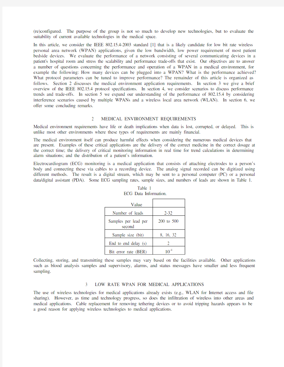
Electrocardiogram (ECG) monitoring is a medical application that consists of attaching electrodes to a person’s body and connecting these via cables to a recording device. The analog signal recorded can be digitized using different methods. The result is a digital stream, which may be sent to a personal computer (PC) or a personal data/digital assistant (PDA). Some ECG sampling rates, sample sizes, and numbers of leads are shown in Table 1.
Table 1
ECG Data Information.
Value
Number of leads 2-32
200 to 500
Samples per lead per
second
Sample size (bit) 8, 16, 32
End to end delay (s) 2
Bit error rate (BER) 10-4
Collecting, storing, and transmitting these samples may vary based on the facilities available. Other applications such as blood analysis samples and supervisory, alarms, and status messages have smaller and less frequent sampling.
3 LOW RATE WPAN FOR MEDICAL APPLICATIONS
The use of wireless technologies for medical applications already exists (e.g., WLAN for Internet access and file sharing). However, as time and technology progress, so does the infiltration of wireless into other areas and medical applications. Cable replacement for removing tethering devices or to avoid tripping hazards appears to be a good reason for applying wireless technologies to medical applications.
We examine the new low rate IEEE Std. 802.15.4-2003 and its application to some low rate medical applications. The IEEE Std. 802.15.4 describes a very low rate wireless technology that is designed for communication among wireless devices within a short range of each other, using very low power (most likely battery operated) and with low data rate requirements. The WPAN that is created when using this technology may be classified in one of two types: unslotted or slotted. For the unslotted WPAN all devices are considered peers with respect to one another and all devices contend to access the wireless resource. For the slotted WPAN a structure is imposed on the wireless resource. This structure is shown in Figure 1.
contention period
a) Unslotted
b) Slotted
Figure 1 WPAN structure of wireless resource.
Within the slotted structure there are potentially three time periods. The first is for the sending of the beacon frame. The two beacon frames bound this structure. The second is the period directly following the beacon frame. This second period may be considered the active portion of the structure because it is during this time period when transmission and receptions may occur. This second or active time period may be further divided into a contention period and a non-contention period. During the contention period all devices are considered peers and compete equally for the resource using a carrier sensed multiple access with collision avoidance (CSMA/CA) mechanism. During the non-contention period resources can be allocated for use on a per device basis. The third period, if it exists, is an idle period where nothing is expected to be transmitted or received. This permits power savings while still maintaining synchronization with the beacon and a bound on delay.
As with most IEEE 802 standards, the 802.15.4 standard defines a physical layer and a medium access control (MAC) sublayer. The physical layer defines three medium-dependent wireless raw data rates covering three different frequency bands. These are 20, 40, and 250 kbit/s using the 868-868.6, 902-928, and 2400-2483.5 MHz frequency bands, respectively. In these respective frequency bands there are one, ten, and sixteen channels at these rates.
The MAC sublayer defines two CSMA/CA mechanisms, one for use in each of the two types of WPANs. Each have a number of default parameters that control the CSMA/CA process. For example the backoff exponent parameter bounds the range (from which a random value is selected) of the delay on how often an attempt is made to sense the wireless medium, and the maximum number of CSMA/CA backoffs parameter determines the number of attempts to sense the wireless medium for an idle condition before declaring a failure to transmit that particular frame.
We study only the unslotted WPAN when using the 2450 MHz band for a number of reasons. The 2450 MHz band provides the most channels (i.e., 16) at the highest data rates. The unslotted WPAN has the least overhead (i.e., no beacon frames). Based on the increased complexity for the slotted WPAN when compared to the unslotted WPAN, it is believed that the first devices available on the market will have these characteristics.
4 WPAN PERFORMANCE EVALUATION RESULTS
We present simulation results to evaluate the performance of a low-rate WPAN in a healthcare environment. Our simulation environment is based on detailed MAC, physical layer (PHY) and channel models for the IEEE 802.15.4 (low-rate WPAN). The channel model consists of a geometry-based propagation model for the signals, as
well as a noise model based on additive white Gaussian noise (AWGN). For the indoor channel, we apply a propagation model consisting of two parts: (1) line-of-sight propagation (free-space) for the first 8 meters, and (2) a propagation exponent of 3.3 for distances over 8 meters [2]. We develop models for the low-rate WPAN access protocols using the OPNET12 network simulator and configure the applications available in the simulator library.
In general, we find that performance results vary according to the network configuration, usage scenario and application considered [3]. In this section, we focus on two experiments that demonstrate the suitability of the IEEE 802.15.4 standard specifications to a healthcare/ medical environment. The first experiment focuses on scalability and the performance of the IEEE 802.15.4 technology in a multi-point to point topology, where multiple transmitters are communicating with a single receiver. The second experiment stresses the effect on the network performance of packet segmentation and tuning the backoff parameters of the IEEE 802.15.4 protocol.
We first describe the application and scenarios used before discussing the results obtained. For the WPAN, we consider a patient monitor where the ECG uses multiple leads that produces a 1500 byte frame every 0.25 s, the blood analysis produces a 1024 byte frame every second, supervisory control produces a 512 byte frame every second, and a 384 byte frame containing status or alert information every minute. The parameters used in the simulations are summarized in Table 2. The application parameters for the WPAN are shown in Table 3. Table 2 and Table 3 also contain simulation and application parameters for a WLAN, which are used in section 5 when we discuss interference between the WPAN and a WLAN.
Table 2
Simulation parameters.
Value
Length of simulation run (s) 600
WPAN parameters
Transmitted power (mW) 1
Packet header (bit) 72
Minimum Backoff Exponent 3 (default)
Maximum Number of Backoffs 4 (default)
WLAN parameters
Transmitted power (mW) 25
Packet header (bit) 224
Packet payload 12 000
1 OPNET and OPNET Modeler are registered trademarks of OPNET Technologies, Inc.
2 Certain commercial equipment, instruments, or materials are identified in this paper in order to specify the experimental procedure adequately. Such identification is not intended to imply recommendation or endorsement by the National Institute of Standards and Technology, nor is it intended to imply that the materials or equipment identified are necessarily the best available for the purpose.
Table 3.
Application parameters.
Distribution Value
WPAN
Alarms & status Supervisory & control Blood analysis
ECG
Constant 384 byte / 60 s,
512 byte / s,
1024 byte / s
1500 byte / 0.25 s WLAN FTP
File size (Mbyte) Constant 960
WLAN HTTP
Page interarrival time (s) Exponential 5 Number of objects per page Constant 2
Object 1 size (byte) Constant 10,000 Object 2 size (byte) Uniform 200 000 or 600 000
WLAN E-mail
Send interarrival time (s) Exponential120
Send group Constant 3 Receive interarrival time (s) Exponential60 Receive group Constant 3
E-mail size (byte) Exponential 1 024
WLAN video
Frame rate (frame/s) Constant 1
Frame size (byte) Constant 17 280
We use the configuration shown in Figure 2 that may be common to a hospital environment. It consists of a number of low-rate WPAN devices such as sensors communicating to a central node. The receiver is placed at the centre of a 1-meter radius, while the transmitters are placed along the perimeter of the disc. This WPAN topology is used for the scalability experiments.
Figure 2 WPAN topology.
The performance metrics used include the MAC access delay, the percentage of packets dropped at the transmitter’s application layer, and the percentage of packets dropped at the MAC layer’s receiver node. In addition, a goodput measure is computed as the number of successful packets received at the receiver’s application layer divided by the available capacity (in number of application layer packets that could be transmitted over the medium). Each data point collected is averaged over 10 simulation trials using a different random seed for each trial. In addition to the mean value, we verify that statistical variation around the mean values are small and fall within a 95% confidence interval.
Results
4.1 Baseline
This first set of performance results are based on the given WPAN applications (see Table 3) without modifications and the WPAN defaults (see Table 2) as stated in IEEE 802.15.4.
From Figure 3 we see that the packet delays are well within the medical requirements for delay, if this WPAN segment is considered the entire network. The decrease in the delay for the 1500 byte application as more transmitters are added to the topology, is due to two factors: the way that the application’s data is sent and the way that the delay is calculated. Since the 1500 byte packet is too large for a single IEEE 802.15.4 MAC frame, multiple MAC frames (i.e., 16) are generated for each 1500 byte packet. All of these MAC frames are then queued, but once an error occurs in the transmission of one MAC frame (due to timeout or maximum retransmission attempts), then the remaining MAC frames are deleted from the queue. Effectively there are fewer frames waiting in the MAC queue leading to the lower delays observed and the dramatic decrease in goodput as seen in Figure 4. The offered load on the WPAN reaches its maximum with just two devices. Adding just one more transmitter results in an overload of the WPAN’s capacity. The lower delay and lower goodput result because the application packet is composed of multiple MAC frames and if one MAC frame is lost during the CSMA/CA process, then all of the remaining queued MAC packets are dropped. Packet losses are shown in Figure 5 and Figure 6. Figure 5 shows the packets dropped as seen by the application at the transmitter, while Figure 6 shows the MAC sublayer frame loss at the receiver. The difference in these two perspectives shows the likelihood that an application packet will be lost due to a loss of a single MAC frame in the attempt to access the wireless
resource versus the likelihood to lose a MAC packet due to interference of another transmitter (i.e., collision). For the 1500 byte application (ECG) the bit error rate (BER) is unacceptable for three or more transmitters. For the 1024 byte application it takes thirteen transmitters to reach an unacceptable BER. The other applications are not shown, since the number of transmitters studied is not large enough to produce enough load to cause packet loss.
Figure 3 Delay as a function of number of transmitters.
Figure 4 Goodput as a function of number of transmitters.
Figure 5 Percentage of packets dropped as a function of number of transmitters.
Figure 6 Percentage of MAC frame loss
4.2 Packet
Segmentation
Based on the results obtained with the unslotted WPAN using the IEEE 802.15.4 default parameters, the questions we ask are as follows. Could performance be improved if other parameter values are used? Is there a better packaging than the current Ethernet framing for medical applications? To this end we now show the results of various permutations.
Since the medical application using the Ethernet framing is obviously a remnant of the wired local area network, we decide to package the ECG samples into a single WPAN frame. This causes the MAC frames to be spaced out over a longer period, rather than producing a cluster of them at once. The number of MAC frames is approximately the same. This improves the goodput and packet loss as shown in Figure 7. However the delay is worse as is
shown in Figure 8. This is expected given that the total aggregate network load is well beyond the capacity.
Figure 7 Goodput for new ECG packetization
Figure 8 Delay for new ECG packetization
Tuning
Parameter
4.3 Backoff
Since modifying every medical application to fit this particular, or for that matter any, wireless technology is not
practical, we next investigate the performance of the given medical application (i.e, ECG) when different
parameters are used for the CSMA/CA algorithm. Only one parameter is varied while the defaults are used for the other parameters.
The maximum number of CSMA backoffs has a default of 4, but can vary from 0 to 5. This parameter is used to control the number of times a device will attempt to test the wireless resource for availability before declaring a transmission attempt failure for a particular frame. Figure 9 shows the goodput results and Figure 10 shows the delay results of this investigation. As one can see the default value is not the best selection. Decreasing the backoff value and thus increasing the transmitter’s persistence, achieves a higher goodput. However more interesting is the jagged curves, which did not smooth out over multiple or longer simulation runs. (See experiment in subsection 4.4 for further information)
Figure 9 Goodput for 1500 byte/0.25s at various maximum CSMA/CA backoffs
Figure 10 Packet delay for 1500 byte/0.25s at various maximum CSMA/CA backoffs
The minimum value for the backoff exponent has a default of 3 but can vary from 0 to 3. This parameter is used to control the range of possible random backoff slots before attempting to test the wireless resource for availability. Figure 11 shows the goodput results and Figure 12 shows the delay results of this investigation. As one can see here too the default value does not produce the best possible results. Reducing the backoff exponent leads to lower
delays and increased goodput.
Figure 11 Goodput for 1500 byte / 0.25 s using various backoff exponent values
Figure 12 Delays for 1500 byte / 0.25 s using various backoff exponent values
4.4 Exponential Packet Inter-arrival
The jagged curves obtained in the previous experiments where the CSMA backoff intervals and exponents were
reduced warrant further investigation to determine the origin of the sawtooth pattern exhibited. We conjecture that
this effect is due to some sort of synchronization among transmitters with constant traffic generation and limited randomness in the backoff period. In order to validate this claim, we make the packet inter-arrival distribution exponential and rerun the simulations. Observe that using exponential arrivals does produce smooth curves (see Figures 13 and 14). Note that changing the arrival of frames from constant to exponential may not be applicable to the medical environment since the ECG application produces a constant and periodic stream of frames. Thus we conclude that the randomness included in the CSMA/CA mechanism may not be sufficient to avoid future synchronization of the competing devices’ transmissions depending on the application and traffic patterns.
Figure 13 Goodput using exponential arrival at various backoff exponents
Figure 14 Goodput using exponential arrival at various maximum CSMA/CA backoffs
4.5 Other Parameter Tuning for Future Work
Other factors that may affect performance are the size of the MAC frame and use of the unacknowledged data delivery mechanism.
From a strictly overhead point of view the best possible MAC frame size in the largest allowable (i.e., 127 bytes), which is what we studied. However this may not be optimal when other considerations are taken into account. Since the CSMA/CA mechanism uses a random backoff period before sensing the wireless medium, if a MAC frame is large, then it is highly likely that the sensing will occur during a frame’s transmission. Thus at least another backoff period is required. Also, depending on the relative size of the MAC frame to the backoff interval, more than one backoff interval may be required when transmitting a large MAC frame. This can result in high packet drop rate, as can be seen in Figure 6.
In this article, we only study the acknowledged data delivery mechanism, which requires an acknowledgement from the receiver of the transmitted data frame that it was received. When this service is used the MAC layer will try for an extended period of time to transmit the data frame and receive the acknowledgement before declaring failure and dropping the frame. With the unacknowledged data service the MAC frame, once transmitted, is assumed to have succeeded. If this data service were used, it is expected that the delay will be lower and that number of packets dropped will be smaller.
5 IMPACT OF WIRELESS INTERFERENCE
Since it is highly unlikely that a WPAN using the 802.15.4 will be in an interference free environment, we study
the effects of interference generated by multiple WPANs and a WLAN. First we cover the WPAN on WPAN interference. Secondly we cover the effects of interference in a mixed WLAN and WPAN environment.
5.1 Impact of WPAN on WPAN Interference
For the case of the interference caused by other 802.15.4 WPANs, most can be avoided by selecting one of the 16
channels that does not already contain a WPAN. This channel selection may be accomplished through manual
configuration or by implementing optional dynamic procedures. However in order to investigate this type of interference, we assume the worst possible scenario, where two 802.15.4 WPANs (one for each patient) are located in a single hospital room and each WPAN uses same channel. Each WPAN contains the four separate medical applications described and used in the previous sections. This topology is shown in Figure 15. We assume that there are two monitors 1 meter apart. Each monitor is about 25 cm away from a patient’s bed, that is 150 cm wide. There are four probes (per patient) connected to a monitor and forming a WPAN system.
Figure 15 Hospital room WPAN topology
The packet loss, delay, and goodput from these experiments as seen by the monitors are shown in table 4. There is a 69% goodput per WAPN system and an 18% packet loss observed at each monitor receiver. Thus, the impact of WPAN on WPAN interference may be significant. The packet loss observed is comparable to the one obtained if all transmitters were connected to a single monitor. In this case, the solution is to configure each WPAN system to use different and non-overlapping channels.
Table 4
Packet loss (%) Delay (s) Goodput (%)
Monitor 1 18.10 0.0391 69.77
Monitor 2 18.07 0.0392 69.99
5.2 Impact of WLAN interference on WPAN
Since it is highly likely that a WLAN will exist in the same coverage space as a WPAN, it is important to assess the effect of interference caused by a WLAN on a WPAN and vice versa. This likelihood is assumed since the
802.15.4 wireless technology alone will not provide the necessary capacity for all medical applications in such an environment. In the previous section the performance of the WPAN was in an interference free environment. This allowed us to closely examine the packet loss, delay, and goodput when achieved in the best possible environment and under parameter manipulation. In contrast the experiments discussed in this section use only the default 802.15.4 parameters with the interference caused by a nearby WLAN. Different applications are used by the WLAN system including file transfer protocol (FTP), hyper text transfer protocol (HTTP), electronic mail (Email),
and Video. The application and simulation parameters used for the WLAN nodes are given in Table 2 and Table 3 in section 4.
The 802.15.4 wireless technology, like the WLAN wireless technology, contains optional sensing methods for determining the idle or busy condition of the wireless resource. In the first set of experiments the optional sensing method used is for the detection of only frames that conform to 802.15.4. In the second set of experiments the optional sensing method is for the detection of any type of packet (i.e., WPAN and WLAN). Figure 16 shows the topology used for the WLAN and WPAN interference experiments. A WLAN server is placed 4 meters away from a WLAN station that is 1 meter apart from a WPAN receiver. The distance between the WPAN receiver and WPAN transmitter is set to 1 meter.
Figure 16 WLAN and WPAN topology
The results of these two experiments are shown in two sets of tables, Table 5 and Table 6, each consisting of four results: a) Packet Loss, b) Delay, c) Goodput, and d) WLAN Station loss.
Considering the experiment with one WPAN and one WLAN when the WPAN only detects packets of its own type, one can see that the packet loss to the WPAN is significant, especially when the WLAN is transmitting video (see table 4a). The WLAN FTP and video applications have the most detrimental effect, since these applications occupy the wireless resource most of the time. For video, the WPAN packet loss is 100%, or nearly so for all WPAN applications. For WLAN FTP the packet loss increases as the WPAN applications decrease in output from a packet loss of 13.9% for WPAN ECG to a packet loss of 90.7% for WPAN Alarm and Status. This latter data point is significant in that the likelihood of an alarm indication not reaching its destination is so high that one should not use this technology under these circumstances. The delays are bounded by the CSMA/CA and retransmission built-in functions and procedures.
The results are slightly different when the WPAN carrier sense can also detect the transmission of WLAN packets. In this case, the WPAN packet loss is lower for almost all of the WPAN applications as is shown in Table 5a. The few exceptions are when the WLAN is sending FTP traffic. Since the WPAN is now sensing for WLAN signals, most of its data is lost to the clear channel assessment (CCA) failing to find the medium idle. With the small amount of data to send for the Alarm and Status application, some of it gets sent without colliding. However, there are no successful WPAN packets received or 100% of packet loss for the WLAN video application and the WPAN alarm application. Note that if no packets are received correctly, the goodput is zero and the access delay
calculation is not applicable (N/A). Finally from Table 5d, we note that the WLAN packet loss is negligible when the WPAN is able to detect a WLAN transmission and thus allows the WLAN to get unlimited access to the medium. This provides a preferential treatment to the WLAN traffic.
Tables for Detection of the WPAN packets only Table 5a WPAN Packet Loss (%)
WLAN FTP WLAN HTTP WLAN Email WLAN
Video
WPAN ECG
13.9 9.6 0.06 100 WPAN Blood Analysis
55.1 11.7 0.3 99.75 WPAN Supervisory
69.0 20.1 0.4 99.75 WPAN Alarm Status
90.7 38.6 8.1 100
Table 5b WPAN MAC Delay (s)
WLAN FTP WLAN HTTP WLAN Email WLAN
Video
WPAN ECG
0.058 0.058 0.057 N/A WPAN Blood Analysis
0.044 0.040 0.040 0.029 WPAN Supervisory
0.029 0.024 0.022 0.029 WPAN Alarm Status
0.029 0.022 0.019 N/A Table 5c WPAN Goodput (%)
WLAN FTP WLAN HTTP WLAN Email WLAN
Video
WPAN ECG
68.0 77 99.75 0 WPAN Blood Analysis
25 78.2 99.3 0 WPAN Supervisory
21 79.2 99.3 0 WPAN Alarm Status
0 60 90 0 Table 5d WLAN Station Packet Loss (%)
WLAN FTP WLAN HTTP WLAN Email WLAN
Video
WPAN ECG
3.7 10.7 8.2 2.8 WPAN Blood Analysis
1.6 3.1 10.7 19.1 WPAN Supervisory
1.6 3.1 3.8 19.1 WPAN Alarm Status
1.0 1.0
2.0 2.7
Tables for Detection of all packets Table 6a WPAN Packet Loss (%)
WLAN FTP WLAN HTTP WLAN
WLAN Video WPAN ECG
45.5 3.5 0.07 81.9 WPAN Blood Analysis
74.0 3.8 0.09 52.3 WPAN Supervisory
76.7 7.0 0.30 68.9 WPAN Alarm Status
76.9 18.2 5.66 100
Table 6b WPAN MAC Delay (s)
WLAN FTP WLAN HTTP WLAN
WLAN Video WPAN ECG
0.066 0.058 0.057 0.076 WPAN Blood Analysis
0.061 0.041 0.040 0.094 WPAN Supervisory
0.044 0.024 0.023 0.075 WPAN Alarm Status
0.028 0.022 0.024 N/A Table 6c WPAN Goodput (%)
WLAN FTP WLAN HTTP WLAN
WLAN Video WPAN ECG
10.6 78.9 99.9 0.1 WPAN Blood Analysis
4.3 81.7 100 8.3 WPAN Supervisory
6.7 83.7 99.8 7 WPAN Alarm Status
10 70 100 0
Table 6d WLAN Station Packet Loss (%)
WLAN FTP WLAN HTTP WLAN
WLAN Video WPAN ECG
1.9 3.6 10.2
2.4 WPAN Blood Analysis
1.2 1.6 4.2 7.6 WPAN Supervisory
1.2 1.7 7.2 7.2 WPAN Alarm Status 1.1 1.1
2.4 2.4
6 CONCLUDING
REMARKS
In this article we investigate the use of the wireless technology described in the IEEE 802.15.4 standard specification for medical applications in support of multiple devices with different data rates. Our findings can be summarized as follows.
The CSMA/CA mechanism built into the MAC protocol may limit the utilization of the medium. An aggregate data rate of 130% of the capacity from three transmitters leads to a goodput rate of little more than 50%. Furthermore, as the number of transmitters is increased to 16, the goodput rate drops to 5%.
We explore two different avenues to alleviate this scalability problem. First, we explore moving beyond the legacy Ethernet interface, and defining a segmentation of the application framing structure into smaller chunks that fit into IEEE 802.15.4 MAC packets. This approach improves the goodput rate up to 90% for two/three transmitters, and 40% for 16 transmitters. An obvious side effect for this method is that the access delay can grow significantly, proportionally to the aggregate network load.
Second, we look into tuning the backoff parameters that control the CSMA/CA mechanism. We observe that by increasing the transmission persistence, i.e. reducing the maximum number of CSMA/CA backoffs and the backoff exponent to 0, goodput is increased to 60% and 40% for two and 16 transmitters, respectively. The main disadvantage of transmission persistence is a transmission synchronization problem exhibited by the jagged pattern in the goodput curves. We verify that this synchronization is mainly due to the constant nature of the application traffic used and note that the behavior symptoms disappear for exponential packet generation distributions.
In the area of interference we show that a WPAN sharing the same channel with another WPAN has no more interference effect than if all devices were using the same WPAN. However, WLAN interference is detrimental to a WPAN using 802.15.4. It is envisioned that if the penetration of WLAN continues at its current rate, then a WPAN using 802.15.4 will be incapacitated, unless the WLAN is idle most of the time or on a different channel. Choosing the optional sensing mechanism that detects any packet type for the 802.15.4 WPAN will improve its performance, but perhaps not enough to make a difference.
AKNOWLEDGEMENTS
We wish to acknowledge the members of the IEEE 1073, especially Jan Wittenber, developing the technical report on the RF wireless for medical devices, without their help we would not have current medical application information.
REFERENCES
[1] IEEE Std. 802.15.4 – 2003, Standard for Telecommunications and Information Exchange Between Systems –
Local Area Metropolitan Area Networks – Specific Requirements - Wireless Medium Access Control (MAC) and Physical Layer (PHY) Specifications for Low Rate Wireless Personal Area Networks (WPAN)
[2] A. Kamerman and N. Erkocevic, “Microwave oven interference on wireless LANs operating in the 2.4 GHz
ISM band,” Proceedings of the 8th IEEE International Symposium on Personal, Indoor and Mobile Radio Communications, Vol.3, pp.1221-1227, 1997.
[3] N. Golmie, R.E. Van Dyck, A. Soltanian, A. Tonnerre, and O. Rebala, “Interference Evaluation of Bluetooth
and IEEE 802.11b Systems,” ACM Wireless Network, WINET, Vol. 9, pp. 200-211, May 2003.