电动汽车充电桩设计外文文献翻译最新译文
- 格式:docx
- 大小:43.58 KB
- 文档页数:19
毕业设计(论文)外文文献翻译文献、资料中文题目:锂电池充电器的设计文献、资料英文题目:The design of the lithiumbattery charger文献、资料来源:文献、资料发表(出版)日期:院(部):专业:班级:姓名:学号:指导教师:翻译日期: 2017.02.14The design of the lithium battery chargerIntroductionLi-Ion rechargeable batteries are finding their way into many applications due to their size, weight and energy storage advantages.These batteries are already considered the preferred battery in portable computer applications, displacing NiMH and NiCad batteries, and cellular phones are quickly becoming the second major marketplace for Li-Ion. The reason is clear. Li-Ion batteries offer many advantages to the end consumer. In portable computers,Li-Ion battery packs offer longer run times over NiCad and NiMH packs for the same form factor and size, while reducing weight. The same advantages are true for cellular phones. A phone can be made smaller and lighter using Li-Ion batteries without sacrificing run time. As Li-Ion battery costs come down, even more applications will switch to this lighter and smaller technology. Market trends show a continual growth in all rechargeable battery types as consumers continue to demand the convenience of portability. Market data for 1997 shows that approximately 200 million cells of Li-Ion will be shipped, compared to 600 million cells of NiMH. However, it is important to note that three cells of NiMH are equivalent to one Li-Ion cell when packaged into a battery pack. Thus, the actual volume is very close to the same for both. 1997 also marked the first year Li-Ion was the battery type used in the majority of portable computers, displacing NiMH for the top spot. Data for the cellular market showed a shift to Li-Ion in the majority of phones sold in 1997 in Europe and Japan.Li-Ion batteries are an exciting battery technology that must be watched. To make sense of these new batteries, this design guide explains the fundamentals, the charging requirements and the circuits to meet these requirements.Along with more and more the emergence of the handheld electric appliances, to the high performance, baby size, weight need of the light battery charger also more Come more big.The battery is technical to progress to also request continuously to refresh the calculate way more complicatedly is fast with the realization, safety of refresh.Therefore need Want to carry on the more accurate supervision towards refreshing the process, to shorten to refresh time and attain the biggest battery capacity, and prevent°from the battery Bad.The A VR has already led the one step in the competition, is prove is perfect control chip of the next generation charger. The microprocessor of Atmel A VR is current and can provide Flash, EEPROM and 10 ADCses by single slice on the market Of 8 RISC microprocessors of the tallest effect.Because the saving machine of procedure is a Flash, therefore can need not elephant MASK ROM Similar, have a few software editions a few model numbers of stock.The Flash can carry on again to weave the distance before deliver goods, or in the PCB Stick after pack carry on weaving the distance through an ISP again, thus allow to carry on the software renewal in the last one minute.The EEPROM can used for conservancy mark certainly coefficient and the battery characteristic parameter, such as the conservancy refreshes record with the battery that raise the actual usage Capacity.10 A/ Ds conversion machine can provide the enough diagraph accuracy, making the capacity of the good empress even near to its biggest capacity. And other project for attaining this purpose, possible demand the ADC of the exterior, not only take up the space of PCB, but also raised the system Cost.The A VR is thus deluxe language but 8 microprocessors of the designs of unique needleobject" C" currently.The AT90S4433 reference The design is with" C" to write, the elucidation carries on the software design's is what and simple with the deluxe language.Code of C this design is very Carry on adjust easily to suit current and future battery.But the ATtiny15 reference design then use edit collected materials the language to write of, with Acquire the biggest code density.An electric appliances of the modern consumption mainly uses as follows four kinds of batteries:1.Seal completely the sour battery of lead( SLA)2.The battery of NiCd3.The NiMHhydrogen battery( NiMH)4.Lithium battery( Li- Ion)At right choice battery and refresh the calculate way need to understand the background knowledge of these batteries. Seal completely the sour battery( SLA) of lead seals completely the sour battery of lead to mainly used for the more important situation of the cost ratio space and weights, such as the UPS and report to the police the backup battery of the system.The battery of SLA settles the electric voltage to carry on , assist limits to avoid with the electric current at refresh the process of early battery lead the heat.Want ~only the electricity .The pond unit electric voltage does not exceed the provision( the typical model is worth for the 2.2 Vs) of produce the company, the battery of SLA can refresh without limit.The battery of NiCd battery of NiCd use very widespread currently.Its advantage is an opposite cheapness, being easy to the usage;Weakness is from turn on electricity the rate higher.The battery of NiCd of the typical model can refresh 1,000 times.The expired mechanism mainly is a pole to turn over.The first in the battery pack drive over.The unit that all turn on electricity will take place the reversal.For prevent°froming damage the battery wrap, needing to supervise and control the electric voltage without a break.Once unit electric voltage Descend the 1.0 Vs must shut down.The battery of NiCd carries on refresh in settling the electric current by forever . The NiMH hydrogen battery( NiMH) holds to shoot the elephant machine 26 such as the cellular phone, hand in the hand that the importance measure hold equipments, the etc. NiMHhydrogen battery is an usage the most wide.This kind of battery permit.The quantity is bigger than NiCd's.Because lead to refresh and will result in battery of NiMH lose efficacy, carry on measuring by the square in refresh process with.Stop is count for much in fit time.Similar to battery of NiCd, the pole turn over the battery also will damage.Battery of NiMH of from turn on electricity the rate and is probably 20%/ month.Similar to battery of NiCd, the battery of NiMH also settles the electric current to refresh .Other batteries says compare in lithium battery( Li- Ion) and this texts, the lithium battery has the tallest energy/ weight to compare to compare with energy/ physical volume.Lithium battery Settle the electric voltage to carry on refresh with , want to have the electric current restrict to lead the heat in the early battery of refresh the process by avoid at the same time.When refresh the electric current.Descend to produce the minimum electric current of the enactment of company will stop refresh.Leading to refresh will result in battery damage, even exploding.The safety of the battery refreshes the fast charge machine( namely battery can at small be filled with the electricity in 3 hours, is usually a hour) demand of the modern.Can to the unit electric voltage, refresh the electric current and the battery temperatures to carry on to measure by。

毕业设计(论文)外文资料翻译系(院):电子与电气工程学院专业:电气工程及其自动化姓名:学号:外文出处:2007 HERE COME THE... CLEANER,GREENER CARS附件: 1.外文资料翻译译文;2.外文原文。
附件1:外文资料翻译译文2007年来了...清洁,环保汽车一个全新的领域,在柴油发动机上使用电气混合燃料电池。
这个说法是针对混合动力汽车:美国人爱他们,不过只是猜测。
一些环保人士一直在疑惑,有没有更大的混合电池组,能不能够直接插在墙上进行充电,能不能提供动力让你开车去上班,电力与小型燃气发动机使其变为可能。
这个概念最初是一个环保主义者的梦想,是来自的费利克斯克莱默,他推动了公用事业支持插件的合作。
但现在电动汽车走向市场,就像其他高科技绿色汽车当年发展的情况一样。
清洁汽车新的一天清洁和环保汽车技术正在蒸蒸日上。
可充电混合动力车,在工业发展上展现了比1900年的黄金岁月高很多的研究和开发热情。
当汽油、蒸汽、电动车在市场上进行竞争,许多公司如通用汽车、还在嘲弄像罗杰和我这样的人,是谁扼杀了电动汽车的发展?事实上,美国通用汽车公司是第一个成功制造出了可充电混合动力车的公司,他们使用了一个有趣的新方法。
他们正在研发一种全新的推进系统,在最近的底特律车展上展示,那就是雪佛兰伏特。
随着seesawing对未来石油和汽油价格的不确定性,美国人终于将注意力集中在寻找燃油经济性车辆和展望他们的下一个大型多功能运动型车。
一个由具有很大影响力的公司JD Power and Associates去年夏天对消费者的调查发现,让人吃惊的是有57%的受访者会考虑购买他们的下一个混合动力汽车,有49%的购车者会考虑E85乙醇动力汽车。
另一项由Frost&Sullivan的调查发现约有80%的人更关注较一年前的燃油价格。
几乎有一半的人说,如果燃油价格持续上涨的话他们会考虑购买更省油的汽车或混合动力汽车。
而从居住在美国的市民的调查中发现,有五分之一的让人印象深刻的说道,他们也开始使用替代交通工具:诸如自行车,步行,公共交通和电动汽车等等。
轮毂式电动汽车驱动系统外文文献翻译、中英文翻译、外文翻译The wheel type electric car is a type of electric car thatutilizes a driving system。
There are two main forms of this system: the direct driving type ___。
This system is installed on the wheel hub of the motor。
___。
n。
main cer。
___。
it allows for the ___。
making electric control technology possible。
As a result。
the wheel type electric car is expected to e the ___ electric cars.2.Advantages and disadvantagesThe wheel type electric car has many advantages。
First。
it has a simple and compact structure。
Second。
it has high n efficiency。
which improves the overall performance of the car。
Third。
it has good ___。
it has a low noise level。
However。
there are also some disadvantages。
First。
the cost of the wheel type electric car is relatively high。
Second。
the maintenance costis also high。
Third。
the wheel type electric car has ___.The wheel type electric car has a simple and compact structure。
关于新能源充电管理系统的外文文献
对于新能源充电管理系统的外文文献,我们可以从多个角度来
寻找相关信息。
首先,我们可以从学术数据库如Google 学术、
IEEE Xplore、ScienceDirect等搜索相关的期刊论文和学术文章。
在搜索时,可以使用关键词如"new energy charging management system"、"renewable energy charging system"、"electric vehicle charging system"等来获取相关的外文文献。
另外,我们还可以查阅相关的国际会议论文集,例如国际清洁
能源大会(International Conference on Clean Energy)或国际
电力系统与清洁能源大会(International Conference on Power Systems and Clean Energy)等会议的论文集,这些会议通常会涵
盖新能源充电管理系统的最新研究成果。
此外,还可以寻找相关的专业书籍和技术报告,这些书籍和报
告通常会详细介绍新能源充电管理系统的原理、设计和应用。
通过
搜索国际出版的书籍和技术报告,可以获取到丰富的外文文献资料。
除了以上途径,还可以关注国际知名能源管理和电力系统领域
的学者和专家的研究成果,他们在国际期刊上发表的论文和专著都
是宝贵的外文文献资源。
总的来说,要全面了解新能源充电管理系统的外文文献,我们需要充分利用学术数据库、国际会议论文集、专业书籍和技术报告等多种渠道,从不同的角度获取相关信息,以便全面深入地了解该领域的最新研究成果和发展动态。
Electric patrol carElectric patrol car is a kind of for security, peacekeepers special design and development of car. The car is especially suitable for the public security patrol, pedestrian street, golf courses, tourist attractions, real estate (garden district), the large enterprises, departments and units, park, places of entertainment, sports venues, colleges and universities, hospitals, nursing homes, railway stations, airports, docks and other areas of traffic tools. Electric patrol car general can take two to eight, for four-wheel direction disc electric car, install a caution light, horn and propaganda device.This kind of car can be roughly divided into open door car, patrol cars, minibuses and other patrol.An electric patrol car is a car powered by an electric motor rather than a gasoline engine.From the outside,you would probably have no idea that a car is electric.In most cases,converting a gasoline-powered car creates electrics cars,and in that case it is impossible to tell.When you drive an electric car,often the only thing that clues you in toits true nature is the fact it is nearly silent.Under the hood,there are a lot of differences between gasoline and electric cars:The gasoline engine is replaced by an electric motor.The electric motor gets its power from a controller. The controller gets its power from an arry of echargeable batteries.The electric car battery drive, not only is the first choice of police patrol motor vehicle, and at the same time, urban management and law enforcement good helper. May many consumers hope electric car's endurance mileage as long as possible, so can more convenient, can and car comparable, if that's the case but to follow the endurance mileage long electric car "value" is also very high, and the high price is also not necessarily can buy endurance mileage longer electric car, electric endurance mileage is China the whole new energy electric car facing technical problem, so I want to have a long endurance mileage need new energy technology development.REFERENCES参考文献1.Martin W. Stockel,Martin T. Stockel. Auto Fundalmentals.Goodheart Wilcox Company,2003,12.William H. Crouse,Donald L. Anglin. Automotive Mechanics. McGraw-Hill Science/Engineering/Math, 2002.13.Julian Happian Smith.An Intruduction to Moden Vehicle Design. Butterworth-Heinenmann.20024.Herbert E. Elliger. Automotive Engines. Prentic Hall, Inc. 20015.邓贤贵.汽车专业英语.北京:人民交通出版社.20016.http://auto. Howstuffworks. Com。

Ultrasonic ranging system designPublication title: Sensor Review. Bradford: 1993.Vol.ABSTRACT: Ultrasonic ranging technology has wide using worth in many fields, such as the industrial locale, vehicle navigation and sonar engineering. Now it has been used in level measurement, self-guided autonomous vehicles, fieldwork robots automotive navigation, air and underwater target detection, identification, location and so on. So there is an important practicing meaning to learn the ranging theory and ways deeply. To improve the precision of the ultrasonic ranging system in hand, satisfy the request of the engineering personnel for the ranging precision, the bound and the usage, a portable ultrasonic ranging system based on the single chip processor was developed.Keywords: Ultrasound, Ranging System, Single Chip Processor1. IntroductiveWith the development of science and technology, the improvement of people’s standard of living, speeding up the development and construction of the city. Urban drainage system have greatly developed their situation is construction improving. However, due to historical reasons many unpredictable factors in the synthesis of her time, the city drainage system. In particular drainage system often lags behind urban construction. Therefore, there are often good building excavation has been building facilities to upgrade the drainage system phenomenon. It brought to the city sewage, and it is clear to the city sewage and drainage culvert in the sewage treatment system.Co mfort is very important to people’s lives. Mobile robots designed to clear the drainage culvert and the automatic control system Free sewage culvert clear guarantee robots, the robot is designed to clear the culvert sewage to the core. Control system is the core component of the development of ultrasonic range finder. Therefore, it is very important to design a good ultrasonic range finder.2. A principle of ultrasonic distance measurementThe application of AT89C51:SCM is a major piece of computer components are integrated into the chip micro-computer. It is a multi-interface and counting on the micro-controller integration, and intelligence products are widely used in industrial automation. and MCS-51 microcontroller is a typical and representative.Microcontrollers are used in a multitude of commercial applications such as modems, motor-control systems, air conditioner control systems, automotive engine and among others. The high processing speed and enhanced peripheral set of these microcontrollers make them suitable for such high-speed event-based applications. However, these critical application domains also require that these microcontrollers are highly reliable. The high reliability and low market risks can be ensured by a robust testing process and a proper tools environment for the validation of these microcontrollers both at the component and at the system level. Intel Plaform Engineering department developed an object-oriented multi-threaded test environment for the validation of its AT89C51 automotive microcontrollers. The goals of this environment was not only to provide a robust testing environment for the AT89C51 automotive microcontrollers, but to develop an environment which can be easily extended and reused for the validation of several other future microcontrollers. The environment was developed in conjunction with Microsoft Foundation Classes(AT89C51).1.1 Features* Compatible with MCS-51 Products* 2Kbytes of Reprogrammable Flash MemoryEndurance: 1,000Write/Erase Cycles* 2.7V to 6V Operating Range* Fully Static operation: 0Hz to 24MHz* Two-level program memory lock* 128x8-bit internal RAM* 15programmable I/O lines* Two 16-bit timer/counters* Six interrupt sources*Programmable serial UART channel* Direct LED drive output* On-chip analog comparator* Low power idle and power down modes1.2 DescriptionThe AT89C2051 is a low-voltage, high-performance CMOS 8-bit microcomputer with 2Kbytes of flash programmable and erasable read only memory (PEROM). The device is manufactured using Atmel’s high density nonvolatile memory technology and is compatible with the industry standard MCS-51 instruction set and pinout. By combining a versatile 8-bit CPU with flash on a monolithic chip, the Atmel AT89C2051 is a powerful microcomputer which provides a highly flexible and cost effective solution to many embedded control applications.The AT89C2051 provides the following standard features: 2Kbytes of flash,128bytes of RAM, 15 I/O lines, two 16-bit timer/counters, a five vector two-level interrupt architecture, a full duplex serial port, a precision analog comparator, on-chip oscillator and clock circuitry. In addition, the AT89C2051 is designed with static logicfor operation down to zero frequency and supports two software selectable power saving modes. The idle mode stops the CPU while allowing the RAM, timer/counters, serial port and interrupt system to continue functioning. The power down mode saves the RAM contents but freezer the oscillator disabling all other chip functions until the next hardware reset.1.3 Pin Configuration1.4 Pin DescriptionVCC Supply voltage.GND Ground.Prot 1Prot 1 is an 8-bit bidirectional I/O port. Port pins P1.2 to P1.7 provide internal pullups. P1.0 and P1.1 require external pullups. P1.0 and P1.1 also serve as the positive input (AIN0) and the negative input (AIN1), respectively, of the on-chip precision analog comparator. The port 1 output buffers can sink 20mA and can drive LED displays directly. When 1s are written to port 1 pins, they can be used as inputs. When pins P1.2 to P1.7 are used as input and are externally pulled low, they will source current (IIL) because of the internal pullups.Port 3Port 3 pins P3.0 to P3.5, P3.7 are seven bidirectional I/O pins with internal pullups. P3.6 is hard-wired as an input to the output of the on-chip comparator and is not accessible as a general purpose I/O pin. The port 3 output buffers can sink 20mA. When 1s are written to port 3 pins they are pulled high by the internal pullups and can be used as inputs. As inputs, port 3 pins that are externally being pulled low will source current (IIL) because of the pullups.Port 3 also serves the functions of various special features of the AT89C2051 as listed below.1.5 Programming the FlashThe AT89C2051 is shipped with the 2 Kbytes of on-chip PEROM code memory array in the erased state (i.e., contents=FFH) and ready to be programmed. The code memory array is programmed one byte at a time. Once the array is programmed, to re-program any non-blank byte, the entire memory array needs to be erased electrically.Internal address counter: the AT89C2051 contains an internal PEROM address counter which is always reset to 000H on the rising edge of RST and is advanced applying a positive going pulse to pin XTAL1.Programming algorithm: to program the AT89C2051, the following sequence is recommended.1. power-up sequence:Apply power between VCC and GND pins Set RST and XTAL1 to GNDWith all other pins floating , wait for greater than 10 milliseconds2. Set pin RST to ‘H’ set pin P3.2 to ‘H’3. Apply the appropriate combination of ‘H’ or ‘L’ logic to pins P3.3, P3.4, P3.5,P3.7 to select one of the programming operations shown in the PEROM programming modes table.To program and Verify the Array:4. Apply data for code byte at location 000H to P1.0 to P1.7.5.Raise RST to 12V to enable programming.5. Pulse P3.2 once to program a byte in the PEROM array or the lock bits. The byte-write cycle is self-timed and typically takes 1.2ms.6. To verify the programmed data, lower RST from 12V to logic ‘H’ level and set pins P3.3 to P3.7 to the appropriate levels. Output data can be read at the port P1 pins.7. To program a byte at the next address location, pulse XTAL1 pin once to advance the internal address counter. Apply new data to the port P1 pins.8. Repeat steps 5 through 8, changing data and advancing the address counter for the entire 2 Kbytes array or until the end of the object file is reached.9. Power-off sequence: set XTAL1 to ‘L’ set RST to ‘L’Float all other I/O pins Turn VCC power off2.1 The principle of piezoelectric ultrasonic generatorPiezoelectric ultrasonic generator is the use of piezoelectric crystal resonators to work. Ultrasonic generator, the internal structure as shown, it has two piezoelectric chip and a resonance plate. When it’s two plus pulse signal, the frequency equal to the intrinsic piezoelectric oscillation frequency chip, the chip will happen piezoelectric resonance, and promote the development of plate vibration resonance, ultrasound is generated. Conversely, it will be for vibration suppression of piezoelectric chip, the mechanical energy is converted to electrical signals, then it becomes the ultrasonic receiver.The traditional way to determine the moment of the echo’s arrival is based on thresholding the received signal with a fixed reference. The threshold is chosen well above the noise level, whereas the moment of arrival of an echo is defined as the first moment the echo signal surpasses that threshold. The intensity of an echo reflecting from an object strongly depends on the object’s nature, size and distance from the sensor. Further, the time interval from the echo’s starting point to the moment when it surpasses the threshold changes with the intensity of the echo. As a consequence, a considerable error may occur even two echoes with different intensities arriving exactly at the same time will surpass the threshold at different moments. The stronger one will surpass the threshold earlier than the weaker, so it will be considered as belonging to a nearer object.2.2 The principle of ultrasonic distance measurementUltrasonic transmitter in a direction to launch ultrasound, in the moment to launch the beginning of time at the same time, the spread of ultrasound in the air, obstacles on his way to return immediately, the ultrasonic reflected wave received by the receiverimmediately stop the clock. Ultrasound in the air as the propagation velocity of 340m/s, according to the timer records the time t, we can calculate the distance between the launch distance barrier(s), that is: s=340t / 23. Ultrasonic Ranging System for the Second Circuit DesignSystem is characterized by single-chip microcomputer to control the use of ultrasonic transmitter and ultrasonic receiver since the launch from time to time, single-chip selection of 875, economic-to-use, and the chip has 4K of ROM, to facilitate programming.3.1 40 kHz ultrasonic pulse generated with the launchRanging system using the ultrasonic sensor of piezoelectric ceramic sensorsUCM40, its operating voltage of the pulse signal is 40kHz, which by the single-chip implementation of the following procedures to generate.puzel: mov 14h, # 12h; ultrasonic firing continued 200msHere: cpl p1.0; output 40kHz square wavenop;nop;nop;djnz 14h, here;retRanging in front of single-chip termination circuit P1.0 input port, single chip implementation of the above procedure, the P1.0 port in a 40kHz pulse output signal, after amplification transistor T, the drive to launch the first ultrasonic UCM40T, issued 40kHz ultrasonic pulse, and the continued launch of 200ms. Ranging the right and the left side of the circuit, respectively, then input port P1.1 and P1.2, the working principle and circuit in front of the same location.3.2 Reception and processing of ultrasonicUsed to receive the first launch of the first pair UCM40R, the ultrasonic pulse modulation signal into an alternating voltage, the op-amp amplification IC1A and after polarization IC1B to IC2. IC2 is locked loop with audio decoder chip LM567, internal voltage-controlled oscillator center frequency of f0=1/1.1R8C3, capacitor C4 determinetheir target bandwidth. R8-conditioning in the launch of the high jump 8 feet into a low-level, as interrupt request signals to the single-chip processing.Ranging in front of single-chip termination circuit output port INT0 interrupt the highest priority, right or left location of the output circuit with output gate IC3A access INT1 port single-chip, while single-chip P1.3 and P1.4 received input IC3A, interrupted by the process to identify the source of inquiry to deal with, interrupt priority level for the first left right after. Part of the source code is as follows:Receivel: push pswpush accclr ex1; related external interrupt 1jnb p1.1, right; P1.1 pin to 0, ranging from right to interrupt service routine circuitjnb p1.2, left; P1.2 pin to 0, to the left ranging circuit interrupt service routinereturn: SETB EX1; open external interrupt 1pop accpop pswretiright: …; right location entrance circuit interrupt service routineAjmp Returnleft: …; left ranging entrance circuit interrupt service routineAjmp Return3.3 The calculation of ultrasonic propagation timeWhen you start firing at the same time start the single-chip circuitry within the timer T0, the use of timer counting function records the time and the launch of ultrasonic reflected wave received time. When you receive the ultrasonic reflected wave, the receiver circuit output a negative jump in the end of INT0 or INT1 interrupt request generates a signal, single-chip microcomputer in response to external interrupt request, the implementation of the external interrupt service subroutine, read the time difference, calculating the distance. Some of its source code is as follows:RECEIVE0: PUSH PSWPUSH ACCCLR EX0; related external interrupt 0MOV R7, TH0; read the time valueMOV R6, TL0CLR CMOV A, R6SUBB A, #0BBH; calculate the time differenceMOV 31H, A; storage resultsMOV A, R7SUBB A, # 3CHMOV 30H, ASETB EX0; open external interrupt 0\POP ACCPOP PSWRETIFor a flat target, a distance measurement consists of two phases: a coarse measurement and a fine measurement:Step 1: Transmission of one pulse train to produce a simple ultrasonic wave.Step 2: Changing the gain of both echo amplifiers according to equation, until the echo is detected.Step 3: Detection of the amplitudes and zero-crossing times of both echoes.Step 4: Setting the gains of both echo amplifiers to normalize the output at, say 3 volts. Setting the period of the next pulses according to the: period of echoes. Setting the time window according to the data of step 2.Step 5: Sending two pulse trains to produce an interfered wave. Testing the zero-crossing times and amplitudes of the echoes. If phase inversion occurs in the echo, determine to otherwise calculate to by interpolation using the amplitudes near the trough. Derive t sub m1 and t sub m2.Step 6: Calculation of the distance y using equation.4、The ultrasonic ranging system software designSoftware is divided into two parts, the main program and interrupt service routine. Completion of the work of the main program is initialized, each sequence of ultrasonic transmitting and receiving control.Interrupt service routines from time to time to complete three of the rotation direction of ultrasonic launch, the main external interrupt service subroutine to read the value of completion time, distance calculation, the results of the output and so on.5、ConclusionsRequired measuring range of 30cm-200cm objects inside the plane to do a number of measurements found that the maximum error is 0.5cm, and good reproducibility. Single-chip design can be seen on the ultrasonic ranging system has a hardware structure is simple, reliable, small features such as measurement error. Therefore, it can be used not only for mobile robot can be used in other detection system.Thoughts: As for why the receiver do not have the transistor amplifier circuit, because the magnification well, integrated amplifier, but also with automatic gain control level, magnification to 76dB, the center frequency is 38k to 40k, is exactly resonant ultrasonic sensors frequency.6、Parking sensor6.1 Parking sensor introductionReversing radar, full name is "reversing the anti-collision radar, also known as" parking assist device, car parking or reversing the safety of assistive devices, ultrasonic sensors(commonly known as probes), controls and displays (or buzzer)and other components. To inform the driver around the obstacle to the sound or a moreintuitive display to lift the driver parking, reversing and start the vehicle around tovisit the distress caused by, and to help the driver to remove the vision deadends and blurred vision defects and improve driving safety.6.2 Reversing radar detection principleReversing radar, according to high-speed flight of the bats in thenight, not collided with any obstacle principles of design anddevelopment. Probe mounted on the rear bumper, according to different price and brand, the probe only ranging from two, three, four, six, eight,respectively, pipe around. The probe radiation, 45-degree angle up and downabout the search target. The greatest advantage is to explore lower than the bumper of the driver from the rear window is difficult to see obstacles, and the police, suchas flower beds, children playing in the squatting on the car.Display parking sensor installed in the rear view mirror, it constantlyremind drivers to car distance behindthe object distance to the dangerous distance, the buzzer starts singing, allow the driver to stop. When the gear lever linked into reverse gear, reversing radar, auto-start the work, the working range of 0.3 to 2.0 meters, so stop when the driver was very practical. Reversing radar is equivalent to an ultrasound probe for ultrasonic probe can be divided into two categories: First, Electrical, ultrasonic, the second is to use mechanical means to produce ultrasound, in view of the more commonly used piezoelectric ultrasonic generator, it has two power chips and a soundingboard, plus apulse signal when the poles, its frequency equal to the intrinsic oscillation frequency of the piezoelectric pressure chip will be resonant and drivenby the vibration of the sounding board, the mechanical energy into electrical signal, which became the ultrasonic probe works. In order to better study Ultrasonic and use up, people have to design and manufacture of ultrasonic sound, the ultrasonic probe tobe used in the use of car parking sensor. With this principle in a non-contactdetection technology for distance measurement is simple, convenient and rapid, easyto do real-time control, distance accuracy of practical industrial requirements. Parking sensor for ranging send out ultrasonic signal at a givenmoment, and shot in the face of the measured object back to the signal wave, reversing radar receiver to use statistics in the ultrasonic signal from the transmitter to receive echo signals calculate the propagation velocity in the medium, which can calculate the distance of the probe and to detect objects.6.3 Reversing radar functionality and performanceParking sensor can be divided into the LCD distance display, audible alarm, and azimuth directions, voice prompts, automatic probe detection function is complete, reversing radar distance, audible alarm, position-indicating function. A good performance reversing radar, its main properties include: (1) sensitivity, whether theresponse fast enough when there is an obstacle. (2) the existence of blind spots. (3) detection distance range.6.4 Each part of the roleReversing radar has the following effects: (1) ultrasonic sensor: used tolaunch and receive ultrasonic signals, ultrasonic sensors canmeasure distance. (2) host: after the launch of the sine wave pulse to the ultrasonic sensors, and process the received signal, to calculate the distance value, the data and monitor communication. (3) display or abuzzer: the receivinghost from the data, and display the distance value and provide differentlevels according to the distance from the alarm sound.6.5 Cautions1, the installation height: general ground: car before the installation of 45 ~55: 50 ~ 65cmcar after installation. 2, regular cleaningof the probe to prevent the fill. 3, do not use the hardstuff the probe surface cover will produce false positives or ranging allowed toprobe surface coverage, such as mud. 4, winter to avoid freezing. 5, 6 / 8 probe reversing radar before and after the probe is not free to swap may cause the ChangMing false positive problem. 6, note that the probe mounting orientation, in accordance with UP installation upward. 7, the probe is not recommended to install sheetmetal, sheet metal vibration will cause the probe resonance, resulting in false positives.超声测距系统设计原文出处:传感器文摘布拉福德:1993年超声测距技术在工业现场、车辆导航、水声工程等领域具有广泛的应用价值,目前已应用于物位测量、机器人自动导航以及空气中与水下的目标探测、识别、定位等场合。
文献出处:Pohl G. The research of hybrid car development [J]. Technological Forecasting and Social Change, 2016, 15(3):57-67.原文The research of hybrid car developmentPohl G.AbstractIncreasingly scarce oil resources and environmental pollution, the problem such as global warming becoming more serious, as a major source of carbon emissions car become focus of research and development of automobile manufacturers, low emissions, zero emissions of choice for new energy vehicles has become the next generation of cars, more and more car manufacturers focus on low emission, low fuel consumption on the development of the car. Therefore, Hybrid Electric Vehicle (Hybrid Electric Vehicle), hereinafter referred to as HEV, as a transition to a zero discharge development models, is starting to get attention. The characteristics of a hybrid car is can make the engine keep in the region of the optimum condition, and good dynamic performance, the hybrid cars have the advantage of low emissions, low pollution.Keywords: Hybrid cars, Control strategy of power matching, Forward simulation1 IntroductionHumans are faced with more and more serious energy shortage crisis; Countries have established their own energy saving strategy. As the national income boost national economy rapid development. Traditional fuel cars used widely in petroleum refining traditional fuels such as gasoline, diesel is belongs to the non-renewable energy, traditional fuel oil reserves and production are in danger of drying up. And car holdings increased year after year, had had a serious of urban traffic congestion, further intensify the energy crisis, and also received a national energy supply security threat. Automobile exhaust gas caused by the environment problem is increasingly serious, such as the tiny particles in urban PM2.5 mainly from automobile exhaust emissions, car exhaust and has become a primary sources of air quality and people's health. Hybrid is refers to the vehicle using conventional fuel (diesel, gasoline, etc.)power and the two methods in electric power, the advantage is in the car at the time of starting, can only rely on motor drive the car, when reaching a certain speed to start the engine. In this way, can make the engine keep the best working state, to obtain good dynamic performance, and power source is battery, do not need to consume fuel alone. The key technology of hybrid car is a hybrid control system assembly, it will affect the performance of hybrid vehicle power performance. Through technology unceasing development, the hybrid control system has been from the traditional motor and engine dispersion structure gradually into the engine, motor and variable speed mechanism of integration. The current hybrid system generally in power transmission lines to distinguish, can be divided into three categories of parallel, series, and mixed type.2 Summary of three hybrid system2.1 series hybrid electric vehicle (SHEV)SHEV type hybrid vehicle, powered by batteries, control module and module DengZi modules, which is in series connection way between them constitute the SHEV powertrain. At work, engine driven generator to generate electricity, directly by the controller to transfer power to the battery or direct drive motor, by variable speed motor to drive a car again. In a small load, the battery to the motor power and drive wheel, when large load, motor direct drive motor power, and thus drive motor. Just started in the car, the battery capacity in a saturated state, the kinetic energy of the battery at this time can achieve auto start demand, when the battery power value is lower than the set value, dynamic auxiliary system starting; When the vehicle's energy demand grows, the battery pack and power module for traction system to transmit power at the same time; When the vehicle energy demand decreases, the auxiliary power system in the guarantee of energy demand driven system at the same time, to the battery. Since the role of the battery, the engine can work in relatively constant work environment, improved their emissions. Series system is widely used in urban area of idle run and repeatedly in the environment, can make the engine area in optimal conditions constant, at the same time, through the deployment of the output of the motor and battery energy to adjust the speed of the car. So you can make theengine to avoid and idle running at low speed, improve the efficiency of the engine, thus reduce exhaust emissions. But its drawback is that a lot of energy conversion, the mechanical efficiency also decreases. Such as Honda's "energy" SHEV is using a fuel battery pack, in the city, under the condition of motor powered by fuel cells, electric motor through a transmission driving car, meet the requirements of the "zero pollution" can effectively improve air quality. When faster and uphill to jointly by the engine, fuel cell and motor vehicle power supply, driving wheel, in order to meet the demand for power vehicle.2.2 Parallel power (PHEV)Parallel hybrid electric vehicle, is composed of motor and motor traction motors at the same time, the motor and engine points belong to two sets of power module, can transmission torque, independent of each other to the automobile transmission system under various conditions can either individual drive and driven vehicle when the vehicle needs to accelerate or is uphill, engine and motor can be transmitted to the drive system of traction at the same time, when the vehicle needs to accelerate or is uphill, engine and motor can be transmitted to the drive system of traction at the same time, when the speed reached cruising speed, car will only to maintain the engine speed. The motor can be used as a generator can directly drive the car. The system with separate no generators, and can drive transmission module to drive the car engine, this system is more similar to the average vehicle driver module, mechanical efficiency loss and almost like a regular car, get more extensive application.Such as V olkswagen golf PHEV vehicles that the engine through the transmission of regulating motor, export torque to the clutch to drive the car forward. When the car starts, battery power supply to the motor, the motor into the engine driving mechanism. After the engine side became the only power source to drive cars, car and driving motor power to the battery at the same time, this time with the traditional cars. In urban conditions, the engine stops, the transmission from, batteries as the only energy supply power to motor wheel driven by a motor to replace the engine. When the vehicle needs to speed up or high load, engine starting transmission gear at the same time, the engine and motor system composition of hybrid models,with maximum torque traction vehicles.2.3 Mixed type power systems (SPHEV)SPHEV usually is in the structure of a PHEV and add a motor, so the engine to provide energy to mechanical transmission output Power Bridge on one hand, can drive the generator to the battery charging at the same time. The engine through a generator which can adjust the speed, the engine can run as far as possible in the working area to high efficiency and low emissions. Distribution of electricity by the controller and motor, transmission to the battery or motor, motor driving force of transmitted power composite structure to the drive axle. Mixed type driving mechanism and structure of control of the parallel and serial mechanism of advantage, can make the motor, engine, generator and other components to better cooperate, under the complicated working conditions on the structure ensures that the car work freedom, so are more likely to achieve control target of low emissions and lower fuel consumption. Composite group compared with tandem type, mixed type less dependence on battery, between energy transfers in less, also more fuel efficient; mixed type compared with parallel connection, the engine operation is affected by the condition of smaller. Three kinds of hybrid electric vehicle, the compound type is based on energy distribution is optimal. Hybrid vehicle technology has been gradually perfected. But because the structure is complex, high cost, during the period of the electric car, before the arrival of hybrid car is a kind of transitional product3 The development of hybrid carsJapan's Toyota and America's big three carmakers to world each big car manufacturers such as turning the hybrids of development and research. Through the development of recent years, hybrid cars in the popularization, the more rapid development in the process of marketization. The world's largest car manufacturers focus on the development of clean energy vehicles, hybrid vehicles become the strategic focus of each big car company, gradually break through the scope of small cars and application in medium and large car slowly, technology is more and more competitive. The world car market in 2009, production of hybrid vehicles already broke through 700000, according to the forecast, to 2016 hybrid cars accounted for15% of the share in the global market. In 1997, Toyota has developed the world's first mass-produced hybrid car, and then in 2001, have developed a hybrid minivans and vans, they have a leading comprehensive control system and electric four-wheel drive hybrid system control unit (TSH), the universal hybrid low fuel consumption, low emissions and improve driving performance, etc., in the forefront of the world. Represented by Toyota's Japanese automakers, is due to the precision of 10 years ago, finally to hybrids such transition of clean energy vehicle technology leading the global auto market now. The Toyota Prius hybrid cars off sales amounted to 208900 cars in 2009, increased by 290% than in 2008, became the first new car sales list.The Obama administration in the United States began to implement the new policy, 2015, 1 million hybrid car gained popularity. The United States is the implementation of tax preferential treatment, the hybrid electric vehicle subsidies is between $2500 to $15000 and at the same time. giving subsidies on lending to the electric car companies. In addition, the United States introduced new vehicle carbon dioxide emissions and car fuel economy law, significantly increase to the requirement of vehicle technology, if not the green energy car technology, auto makers will be difficult to meet the requirements of the new regulations.09 on June 1, tesla, nissan North America, and the ford motor company received $8 billion in loans, mainly used in the r&d and production of pure electric and hybrid cars. Daimlerchrysler, gm and ford motor company in 2003 set up the production of hybrid cars and the fuel cell car batteries used in the development company, they injected $4.6 million to develop the next generation of environmentally friendly vehicles need polymer battery. In August 2005, general motors, such as Daimler signed on to form the world alliance cooperation, development of hybrid system with the letter of intent, Shared their hybrids system with regard to the rich resources of science and technology and advanced technology, and will develop dual-mode hybrid car as the primary target.2010 hybrid cars sold 290300 vehicles in the United States, are 2.8% of the proportion of the U.S. auto market, the proportion is not big, but starting from 1.3% in 2005 to present the trend of rising gradually. Forecast that the yield of hybrids will amount to 873000 vehicles in 2016, its market share will reach 5%.译文混合动力汽车发展研究Pohl G.摘要石油资源日渐匮乏和环境污染、全球变暖等问题的日益严重,作为碳排放主要来源的汽车成为汽车厂商研发的重点,低排放、零排放的新能源汽车成为了下一代汽车的首选,越来越多的汽车生产商把目光放在了低排放、低油耗汽车的研制上。
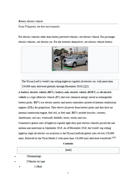
Battery electric vehicleFrom Wikipedia, the free encyclopediaFor electric vehicles other than battery powered vehicles, see electric vehicle. For passenger electric vehicles, see electric car. For the batteries themselves, see electric vehicle battery.A battery electric vehicle (BEV), battery-only electric vehicle (BOEV) or all-electricvehicle is a type ofelectric vehicle (EV) that uses chemical energy stored in rechargeable battery packs. BEVs use electric motors and motor controllers instead of internal combustion engines (ICEs) for propulsion. They derive all power from battery packs and thus have no internal combustion engine, fuel cell, or fuel tank. BEVs include bicycles, scooters,skateboards, rail cars, watercraft, forklifts, buses, trucks and cars.Cumulative global sales of highway-capable light-duty pure electric vehicles passed the one million unit milestone in September 2016. As of December 2016, the world's top selling highway legal all-electric car in history is the Nissan Leafwith global sales of over 250,000 units, followed by the Tesla Model S with more than 158,000 units delivered worldwide.[1][2]Contents∙1Terminology∙2Vehicles by type∙ 2.1Rail∙ 2.2Electric bus∙ 2.2.1Thunder Sky∙ 2.2.2Free Tindo∙ 2.2.3First Fast-Charge, Battery-Electric Transit Bus ∙ 2.3Electric trucks∙ 2.4Electric vans∙ 2.5Electric cars∙ 2.6Special-purpose vehicles∙ 2.7Two- and three-wheeled vehicles∙ 2.8Electric boats∙3Technology∙ 3.1Motors∙ 3.2Motor controllers∙4See also∙5References∙6Further reading∙7External linksTerminologySee also: Hybrid electric vehicle, Plug-in hybrid, and Plug-in electric vehicleVehicles using both electric motors and internal combustion engines are examples of hybrid electric vehicles[3], and are not considered pure or all-electric vehicles because they cannot be externally charged (operate in charge-sustaining mode) and instead they are continually recharged with power from the internal combustion engine and regenerative braking.[4]Hybrid vehicles with batteries that can be charged externally to displace some or all of their internal combustion engine power and gasoline fuel are calledplug-in hybrid electric vehicles (PHEV), and run as BEVs during their charge-depleting mode. PHEVs witha series powertrain are also called range-extended electric vehicles (REEVs), such asthe Chevrolet Volt and Fisker Karma.Plug-in electric vehicles (PEVs) are a subcategory of electric vehicles that includes battery electric vehicles (BEVs), plug-in hybrid vehicles, (PHEVs), andelectric vehicle conversions of hybrid electric vehicles and conventional internal combustionengine vehicles.[4][5]In China, plug-in electric vehicles, together with hybrid electric vehicles are called new energy vehicles (NEVs).[6] However, in the United States, neighborhood electricvehicles (NEVs) are battery electric vehicles that are legally limited to roads with posted speed limits no higher than 45 miles per hour (72 km/h), are usually built to have a top speed of 30 miles per hour (48 km/h), and have a maximum loaded weight of 3,000 lbs.[7]Vehicles by typeThe concept of battery electric vehicles is to use charged batteries on board vehicles for propulsion. Battery electric cars are becoming more and more attractive with the advancement of new battery technology (Lithium Ion) that have higher power and energy density (i.e., greater possible acceleration and more range with fewer batteries) and higher oil prices.[8] BEVs include automobiles, light trucks, and neighborhood electric vehicles.Rail∙Battery electric railcars:Main article: Battery electric multiple unit∙Locomotives:Main article: Battery-electric locomotive∙Electric rail trolley:Main article: Cater MetroTrolleyElectric busMain article: Battery electric busChattanooga, Tennessee operates nine zero-fare electric buses, which have been in operation since 1992 and have carried 11.3 million passengers and covered a distance of 3,100,000 kilometres (1,900,000 mi), They were made locally by Advanced Vehicle Systems. Two of these buses were used for the 1996 Summer Olympics in Atlanta.[9][10]Beginning in the summer of 2000, Hong Kong Airport began operating a16-passenger Mitsubishi Rosa electric shuttle bus, and in the fall of 2000, New York City began testing a 66-passenger battery-powered school bus, an all-electric version of theBlue Bird TC/2000.[11] A similar bus was operated in Napa Valley, California for 14 months ending in April, 2004.[12]The 2008 Beijing Olympics used a fleet of 50 electric buses, which have a range of 130 km (81 mi) with the air conditioning on. They use Lithium-ion batteries, and consume about1 kW·h/mi (0.62 kW·h/km; 2.2 MJ/km). The buses were designed by the Beijing Institute of Technology and built by the Jinghua Coach Co. Ltd.[13] The batteries are replaced with fully charged ones at the recharging station to allow 24-hour operation of the buses.[14]In France, the bus electric phenomenon is in development, but some buses are already operating in numerous cities.[15] PVI, a medium company located in the Paris region, is one of the leader of the market with its brand Gepebus (offering Oreos 2X and Oreos 4X).[16]In the United States, the first battery-electric, fast-charge bus has been in operation in Pomona, California since September 2010 at Foothill Transit. TheProterra EcoRide BE35uses lithium-titanate batteries and is able to fast-charge in less than 10 minutes.[17]In 2014, the first production model all-electric school bus was delivered to the Kings Canyon Unified School District in California’s San Joaquin Valley. The bus was one of four the district ordered. This battery electric school bus, which has 4 sodium nickel batteries, is the first modern electric school bus approved for student transportation by any state.[18]The same technology is used to power the Mountain View Community Shuttles. This technology was supported by the California Energy Commission, and the shuttle program is being supported by Google.[19]Thunder SkyThunder Sky (based in Hong Kong) builds lithium-ion batteries used in submarines and has three models of electric buses, the 10/21 passenger EV-6700 with a range of 280 km (170 mi) under 20 mins quick-charge, the EV-2009 city buses, and the 43 passenger EV-2008 highway bus, which has a range of 300 km (190 mi) under quick-charge (20 mins to 80 percent), and 350 km (220 mi) under full charge (25 mins). The buses will also be built in the United States and Finland.[20]Free TindoTindo is an all-electric bus from Adelaide, Australia. The Tindo (aboriginal word for sun) is made by Designline International[21] in New Zealand and gets its electricity from a solarPV system on Adelaide's central bus station. Rides arezero-fare as part of Adelaide's public transport system.[22]First Fast-Charge, Battery-Electric Transit BusProterra's EcoRide BE35 transit bus, called the Ecoliner by Foothill Transit in West Covina, California, is a heavy duty, fast charge, battery-electric bus. Proterra's ProDrive drive-system uses a UQM motor and regenerative braking that captures 90 percent of the available energy and returns it to the TerraVolt energy storage system, which in turn increases the total distance the bus can drive by 31–35 percent. It can travel 30–40 miles on a single charge, is up to 600 percent more fuel-efficient than a typical diesel or CNG bus, and produces 44 percent less carbon than CNG.[23]Electric trucksMain article: Electric truckFor most of the 20th century, the majority of the world's battery electric road vehicles were British milk floats.[24]Electric vansIn March 2012, Smith Electric Vehicles announced the release of the Newton Step-Van, an all-electric, zero-emission vehicle built on the versatile Newton platform that features a walk-in body produced by Indiana-based Utilimaster.[25]Electric carsMain article: Electric carSee also: List of production battery electric vehicles and electric car use by countryAn electric car is a plug-in battery powered automobile which is propelled by electric motor(s). Although electric cars often give good acceleration and have generally acceptable top speed, the lower specific energy of production batteries available in 2015 comparedwith carbon-based fuels means that electric cars need batteries that are fairly large fraction of the vehicle mass but still often give relatively low range between charges. Recharging can also take significant lengths of time. For journeys within a single battery charge, rather than long journeys, electric cars are practical forms of transportation and can be recharged overnight.Electric cars have the potential of significantly reducing city pollution by having zero tail pipe emissions.[28][29][30] Vehicle greenhouse gas savings depend on how the electricity is generated.[31][32] With the current US energy mix, using an electric car would result in a 30 percent reduction in carbon dioxideemissions.[33][34][35][36] Given the current energy mixes in other countries, it has been predicted that such emissions would decrease by 40 percent in the UK,[37] 19 percent in China,[38] and as little as 1 percent in Germany.[39][40][not in citation given]Electric cars are expected to have a major impact in the auto industry[41][42] given advantages in city pollution, less dependence on oil, and expected rise in gasolineprices.[43][44][45] World governments are pledging billions to fund development of electric vehicles and their components. The US has pledged US$2.4 billion in federal grants for electric cars and batteries.[46] China has announced it will provide US$15 billion to initiate an electric car industry.[47]Cumulative global sales of highway-capable battery electric cars and vans passed the1 million unit milestone in September 2016.[3] The Renault-Nissan Alliance is the leadingall-electric vehicle manufacturer. The Alliance achieved the sales milestone of 350,000all-electric vehicles delivered globally in August 2016.[48] Ranking second is TeslaMotors with over 139,000 electric cars sold between 2008 and June 2016.[49][50]MotorsMain article: Traction motorElectric cars have traditionally used series wound DC motors, a form ofbrushed DC electric motor. Separately excited and permanent magnet are just two of the types of DC motors available. More recent electric vehicles have made use of a variety of AC motor types, as these are simpler to build and have no brushes that can wear out. These are usually induction motors orbrushless AC electric motors which use permanent magnets. There are several variations of the permanent magnet motor which offer simpler drive schemes and/or lower cost including the brushless DC electric motor.Motor controllersMain article: Motor controllerThe motor controller regulates the power to the motor, supplying either variable pulse width DC or variable frequency variable amplitude AC, depending on the motor type, DC or AC.1. Cobb, Jeff (2017-01-09). "Nissan's Quarter-Millionth Leaf Means It's TheBest-Selling Plug-in Car In History". . Retrieved 2017-01-10. As of December 2016, the Nissan Leaf is the world's best-selling plug-in car in history with more than 250,000 units delivered, followed by the Tesla Model S with over 158,000 sales, the Volt/Ampera family of vehicles with 134,500 vehicles sold, and the Mitsubishi Outlander PHEV with about 116,500 units sold through November 2016. These are the only plug-in electric cars so far with over 100,000 global sales.2.^ Jump up to:a b c Cobb, Jeff (2017-01-31). "Tesla Model S Is World's Best-SellingPlug-in Car For Second Year In A Row". . Retrieved2017-01-31. See also detailed 2016 sales and cumulative global sales in the two graphs.3.^ Jump up to:a b Shahan, Zachary (2016-11-22). "1 Million Pure EVs Worldwide: EVRevolution Begins!". Clean Technica. Retrieved 2016-11-23.4.^ Jump up to:a b David B. Sandalow, ed. (2009). Plug-In Electric Vehicles: What Rolefor Washington? (1st. ed.). The Brookings Institution.pp. 2–5.ISBN 978-0-8157-0305-1.See definition on pp. 2.5.Jump up^ "Plug-in Electric Vehicles (PEVs)". Center for Sustainable Energy,California. Retrieved 2010-03-31.6.Jump up^ PRTM Management Consultants, Inc (April 2011). "The China NewEnergy Vehicles Program - Challenges and Opportunities" (PDF). World Bank.Retrieved 2012-02-29. See Acronyms and Key Terms, pp. v7.Jump up^ "What is a neighborhood electric vehicle (NEV)?". AutoblogGreen.2009-02-06. Retrieved 2010-06-09.8.Jump up^ "-". Retrieved 30 May 2015.9.Jump up^ Downtown Electric Shuttle. Retrieved 18 August 2008.10.Jump up^ Success Stories. Retrieved 18 August 2008.11.Jump up^ Solectria Develops an All Electric Version of the Blue Bird TC2000.Retrieved 18 August 2008.12.Jump up^ Electric School Bus. Retrieved 18 August 2008.13.Jump up^ UNDP donates electric buses to Beijing Olympic Games. Retrieved 15August 2008.14.Jump up^ BIT Attends the Delivery Ceremony of the 2008 Olympic GamesAlternative Fuel Vehicles with its Pure Electric Bus. Retrieved 15 August 2008.15.Jump up^(French) http://avem.fr/index.php?page=bus16.Jump up^ "PVI, leader de la traction électrique pour véhicules industriels.".Retrieved 30 May 2015.17.Jump up^ Proterra Launches First Deployment of All-Electric, Zero-Emission Busesby Major Transit Agency. Retrieved October 2011.18.Jump up^ "New All-Electric School Bus Saves California District $10,000+ PerYear". CleanTechnica. Retrieved 2016-03-01.19.Jump up^ "Electric shuttle buses come to Mountain View, thanks to Motiv andGoogle". Silicon Valley Business Journal. 13 January 2015. Retrieved30 May 2015.20.Jump up^ "雷天温斯顿电池有限公司". Retrieved 30 May 2015.21.Jump up^ Andrew Posner (December 19, 2007). "When The Sun Shines DownUnder. . .It Powers a Bus". TreeHugger. Retrieved March 11, 2012.22.Jump up^ All-Electric, Solar-Powered, Free Bus!!! Archived 8 September 2009 atthe Wayback Machine.23.Jumpup^/index.php/mediacenter/companynews/proterra_launches_ first_deployment_of_all-electric_zero-emission_buses/24.Jump up^ "Escaping Lock-in: the Case of the Electric Vehicle". Cgl.uwaterloo.ca.Retrieved 2010-11-27.25.Jump up^ (2012-03-05). "Smith Electric Vehicle LaunchesProduction of All-Electric Newton™ Step Van". .Retrieved 2012-03-05.26.Jump up^ Energy Efficiency & Renewable Energy, U.S. Department ofEnergy and U. S. Environmental Protection Agency and (2017-03-24). "Find a car - Years: 2016–2017 - Vehicle Type: Electric". . Retrieved2017-03-26.27.Jump up^ Baker, David R. (2016-04-01). "Tesla Model 3 reservations top232,000". San Francisco Chronicle. Retrieved 2016-09-14.28.Jump up^ "Should Pollution Factor Into Electric Car Rollout Plans?".. 2010-03-17. Archived from the original on 24 March 2010.Retrieved 2010-04-18.29.Jump up^ "Electro Automotive: FAQ on Electric Car Efficiency & Pollution".. Retrieved 2010-04-18.30.Jump up^ "Clean Air Initiative". Archived from the original on 14 September 2016.Retrieved 30 May 2015.31.Jump up^ Notter, Dominic A.; Kouravelou, Katerina; Karachalios, Theodoros;Daletou, Maria K.; Haberland, Nara Tudela. "Life cycle assessment of PEM FC applications: electric mobility and μ-CHP". Energy Environ. Sci. 8(7): 1969–1985. doi:10.1039/c5ee01082a.32.Jump up^ Notter, Dominic A.; Gauch, Marcel; Widmer, Rolf; Wäger, Patrick; Stamp,Anna; Zah, Rainer; Althaus, Hans-Jörg (2010-09-01). "Contribution of Li-Ion Batteries to the Environmental Impact of Electric Vehicles".Environmental Science & Technology. 44 (17): 6550–6556.doi:10.1021/es903729a. ISSN 0013-936X.33.Jump up^ "Plug-in Hybrid Cars: Chart of CO2 Emis电池电动车电池电动车辆(BEV),仅电池电动车辆(BOEV)或全电动车辆是使用存储在可再充电电池组中的化学能的一种电动车辆(EV)。
太阳能汽车的设计外文翻译中英文英文Design and implementation of the first Duoc-UC'ssolar energy powered carMatías DíazAbstract:Rally racing in solar-powered cars has taken off in recent years in order to demonstrate that green mobility with zero carbon emissions is feasible. The Solar Atacama Race is one of such competitions, taking the participants over 1.400 kms through the driest desert in the world. In this context, this paper outlines the design and implementation process of a solar -and pedal-powered hybrid car built by undergraduate engineering students. The designing steps, components selection and manufacturing process that lead to the implementation of a low-cost prototype are explained. Moreover, details and lessons learned from the first participation and plans for future work are discussed.Keywords- Solar Powered Cars, Atacama Solar Race.IntroductionSolar car races have started approximately in 1980, winning successful ever since. Competitions as the North American Solar Challenge, the World Solar Challenge and the Shell Eco-marathon are well-established races attracting worldwide university student teams, aswell as private enterprise teams compromising with green mobility and the development of the electrical car industry. The Atacama Solar Race brings together teams from all over the world, using the strong solar radiation presents in the Atacama Desert, the driest place in the world. This year is the third edition of Atacama Solar Race, consolidating as the first and only Latin America rally for solar powered vehicles. In Fig. 1 the route for the race is illustrated [1]. The race start at the city of Iquique, traveling 1.400 kms in five days of competition. The rally passes though the cities of Antofagasta, Calama, San Pedro de Atacama, Toconao, Tocopilla and Pozo Almonte. An interesting and challenging fact is the altitude difference between some points of the route. For example, to travel from Calama to San Pedro de Atacama, cars must up from 2.100 m to 3000 m above mean sea level.Atacama Solar Race (ASR) has two categories for the competition. The first category, called “Desafio Solar”, consists of full solar powered vehicles, without economic limitations. Well establish and recognizes teams as Tokai from Japan and Antakari from Chile are competing in this category. In the other hand, the “Ruta Solar” is the second category for low-cost prototypes powered by a combination of solar and pedal power. In “Ruta Solar” teams from Chile, Bolivia, Ecuador, Colombia and Argentina are participating.In this scenario, The School of Engineering of Duoc-UC hasidentified the ASR as an excellent learning platform for students. The motivation for this participation is to promote innovation and research in photovoltaic technologies, educating engineers aware of a more sustainable society, which are able to compete with students from all over the world at international level. Furthermore, the multidisciplinary nature of the project makes it an excellent environment for design, business and engineering students [2], [3]. The whole scope of the project includes aspect related to business and marketing-to raise funding-, administration, logistic - to move the team to the Atacama Desert-and engineering to build the first Duoc-UC's solar powered car, called “Surya Solar Car”. What is more, this paper deals with several engineering aspect as the design and optimization of the electrical and electronics components, the race energy planning in order to minimise the energy consumptions and maximise the autonomy of the car, mechanical design, safety considerations, etc.Design and ImplementationThe “Ruta Solar” technical requirements demand three wheels designs for the category. Moreover, these requirements set a top of USD 7000 as the total cost of the car and regulations strongly demand to ensure the driver safety in any situation. Therefore, the “Surya Solar Car” has been designed to meet these regulations.According with [4], [5] and [6], the design of a solar powered carshould considered electrical and mechanical stages. Both aspect should interact in order to achieve an efficient design. Table 1 present the technical specifications of “Surya Solar Car”, regarding these aspects.A. Mechanical ConsiderationsThe structural body design of a solar powered car can be categorized into two main elements: the cells structure and the chassis. The cells structure is the part of the car where the solar panels are mounted and it is defines for the aerodynamic efficiency of the solar car. A typical cells support structure should take on the shape of a air foil keeping a large horizontal area the solar array. Moreover, according with [7] and [8], the design should considerer proper aerodynamics to reduce the drag force and the rolling resistance. In fact, an accurate mechanic design ensure stable operation and could minimise energy losses when the car is running under aggressive environment conditions, as the present in the Atacama Desert.Every solar car race has strict safety regulations that ensure that the chassis can withstand many different impact scenarios. Thus, the aim of the chassis design process is to achieve a strong and lightweight structure. The chassis must be strong in enough to maintain safe to the driver as well provides proper aerodynamics response.B. Electrical ConsiderationsThe overall diagram of the electric circuit for the proposed solar caris presented in Fig. 4. It consists of mainly 6 parts, which are explained bellow.Solar Panels: In “Surya Solar Car” 6 flexible solar panels have been used. Each panel has 56 cells with a nominal power of 100 W, 21.4 V oc, 5.6 A and efficiency of 22.5%. The panels have been connected in two parallel arrays of three panels in series, in order to achieve an open voltage of 64.2V and 11.2 A.Maximum Power Point Tracking: A commercial Maximum Power Point Tracking (MPPT) Charge Controller have been used to maximise the energy produced by the solar panels to charge the batteries or to feed the motor. The MPPT is from OutBack Power systems and operates until 60A in steady state.Battery and Monitoring System: The critical criteria for select the batteries in an electrical vehicle application is related with the weight-capacity trade-off. For this reason, batteries based in Lithium Ion technology are utilised, regardless its prize is elevate in comparison with other technologies. 3 batteries of 48V and 10 Ah have been using as storage energy system, reaching a storage capability of 1.5 kWh. These batteries are commercialised by Golden Motor and include an internal BMS.Motor and Drive System: the propulsion system is also commercialised by Golden Motors. It consist in a 1 kW PermanentMagnet Motor and drive system which are included in the propulsion wheel, as is shown in Fig. 6.Regarding the electrical safety considerations, protections are disposed in the circuit in order to protect the pilot from any dangerous situation and besides to protect the sensitive electronic devices as the MPPT and BMS. Moreover, 30 A diodes and fuses are connected between the solar panels and the MPPT to prevent inverse power flows.Energy Estimation ApproachIn order to make an accurate race planning is imperative to develop a model to calculate the car energy consumptions. Several works regarding the modelation of solar electric cars have been proposed in recent literatureHowever, due to the main purpose of this paper is devoted to the implementation of the car, the development of an accurate energy modelation is proposed as a future work and just a general energy calculation is presented.A. Application of the Model in the First Race DayThe first day of competition considers a route of 240kms starting in Collahuasi Solar Power Plant and ending near to Calama. This stage is divided in four stretches. The first one stars in Collahuasi Solar Power Plant, and finishes in “Oficina Victoria”, an old saltpetre factory in the middle of the Atacama Desert. The initial altitude of this stretch is1.035m, the final altitude is 961m, and the length is 62.4 km. Fig.7 illustrates a map of the route:Using this information in (1), the resistive force can be calculated as is shown in (4). It is important to note the every factor in (1) is calculated using conventional physics equations, which are not presented in this paper.B. Estimation of the Solar Power CaptureThe batteries have a capacity of 1.5 kWh and the energy required to fulfil the first stage is 3,3172 kWh. Therefore, the solar energy capture has to be estimated.The radiation profile of the first stage is presented in Fig. 8. It is important to note that the data is obtained from the Chilean Ministry of Energy radiation data base webpage [11].Results and Future WorkThe first participation of the School of Engineering of Duoc-UC in the Atacama Solar race has been successful. Surya Team has been able to design and implement a solar-and pedal-hybrid solar powered car that meets the race requirements regarding functionality and safety. Furthermore, the car passed successfully all the technical and safety inspections and participated in the race, as is shown in Fig. 9, to gain experience.Several lessons have been learned in this first participation. Theteam have realised the importance of develop a lightweight, reliable and secure car to be able to resist the entire race. Additionally, it is extremely important to considerate the environmental conditions and have time to test the car before the competence.Technical problems, related precisely with the lack of testing time and lack of knowledge of the route, appears during the race. In fact, the team did not really realize the aggressive wheatear conditions until was in the race. Temperatures until 40°C during the day, decreasing to −15°C in the night, make even more complex the task to cross the driest desert in the world. Furthermore, lateral winds (between 10–14 ms) force to drive with precaution and reducing the speed to prevent any dangerous situation.Even though the team develop an energy estimation model, the design of the car did not considerate instrumentation and telemetry systems for the energy consumptions supervision. Therefore, the accuracy of the energy estimation model presented in (3)could not be checked and was used only as an approximation.During the fourth day of competition, the mechanical system fails due to the extensive use in aggressive environment conditions, forcing to the team to leave the competition for security reasons. However, Surya team is currently working on improved version of Surya to participate in Atacama Solar Race 2016.Major modifications to the first model are been development to solve the problems faced in this version of the race. Some improvements are:Increase the solar panel area.Increase the nominal power of the electrical motor.Incorporate instrumentation to improve the energy supervision.Incorporate a telemetry system and develop an online interface of supervisionDevelop an accurate energy estimation model incorporating radiation prediction to plan the race.Finally, the School of Engineering of Duoc-UC has identified an important academic potential in this kind of projects. Currently, interdisciplinary courses related with the design and implementation of a solar powered car are been structured. Additionally, flexible academic grants are been develop to recognise and validate the time and dedication of the participants as credits for their careers.ConclusionsThe school of Engineering of Duoc-UC has decided to develop student technical and soft skills through the participation in solar car races. Projects as “Surya Solar Car” allows to the students connect engineering knowledge with interdisciplinary, problem-based and hand-on experiences, which lead to the formation of future professionalscommitted with the usage of renewable energies and highly efficiency innovations into personal transportation.In the first participation in Atacama Solar Race, the team managed to design and implement a low-cost prototypes powered by a combination of solar and pedal power. “Surya Solar Car” accomplished all the technical and safety inspections tests and participated in the race, which was the main purpose of the project. The next participation will be in Atacama Solar Race 2016 and the team aims to be in the top three of the category. Extensive work is already been done to develop a car more robust, efficient and lighter than the first version of “Surya”.The School of Engineering of Duoc-UC has identified the ASR as an excellent learning platform for students. In fact, The School of Engineering of Duoc-UC is doing extensive curriculum efforts to promote the integration of problem and project based pedagogies as one of the institutional objectives, providing students with an active role in the acquisition and creation of knowledge.中文Duoc-UC大学首款太阳能汽车的设计与实现Matías Díaz摘要近年来,太阳能汽车的拉力赛逐渐兴起,以证明零碳排放的绿色汽车是可行的。
充电桩翻译充电桩(chōngdiàn zhuāng) 的英文翻译是 "charging station" 或"charging pile"。
充电桩是用来给电动车、混合动力车或其他电动设备充电的设备。
充电桩通常由电源、充电模块、充电控制模块、通信模块等组成。
以下是一些关于充电桩的用法和中英文对照例句:1. 充电桩的数量正在逐渐增加。
The number of charging stations is gradually increasing.2. 这家公司在全国范围内建设了许多充电桩。
This company has built many charging stations nationwide.3. 请将电动车停在充电桩旁边。
Please park the electric vehicle next to the charging station.4. 我需要一张充电桩的使用卡。
I need a charging station access card.5. 这个充电桩支持快速充电。
This charging pile supports fast charging.6. 请将充电插头插入充电桩。
Please insert the charging plug into the charging station.7. 这个充电桩可以同时给两辆车充电。
This charging pile can charge two vehicles simultaneously.8. 这个充电桩可以远程监控充电状态。
This charging station can monitor the charging status remotely.9. 充电桩的使用费用如何计算?How is the usage fee of the charging station calculated?10. 在这个地区,充电桩的覆盖率非常高。
外文翻译:Electric automobile air conditioning system trend ofdevelopment1. electric automobile air conditioning systemGlobal warming, air pollution and higher energy costs and other problems have become more severe, as environmental pollution and energy consumption is one of the major sources of energy saving and emission reduction, the problem is more and more extensive attention, governments and automobile enterprises will be energy saving and environmental protection as the future of automotive technology development direction of energy saving and environmental protection, such as the electric emerge as the times require. Electric vehicle is set car technology, electronic and computer technology, electrochemical technology, energy and new materials technology in one of the high-tech products, and common internal combustion engine vehicles, has the advantages of no pollution, low noise and save petroleum resource characteristics. Based on the above electric vehicle characteristics, it is very likely to become the human a new generation of clean environmentally friendly transportation, its popularization has the inestimable significance.Electric vehicle emerged for electric automobile air-conditioning research and development offerred new task and challenge. Automotive air conditioning function is put inside the temperature, humidity, air cleanliness and air flow is maintained in a comfortable state. In various climate conditions, electric car should maintain the comfortable state, to provide a comfortable driving and riding environment. In addition, a set of energy-saving and efficient air conditioning system on electric vehicle market also plays an important role. Therefore, in the development of electric vehicles at the same time, necessary to support the air conditioning system development and research.For the traditional fuel automobile air-conditioning systems, refrigeration mainly uses the engine driven steam compression refrigeration system for cooling and heating, using waste heat from fuel engine. But for the electric automobile in the pure electric vehicles and fuel cell vehicles, no air conditioning compressor engine as power source, also cannot provide as automotive air conditioning heating using heat source in winter, so it cannot be directly using conventional automotive air conditioning system solutions; for hybrid cars, the engine control means diversity, so the air conditioning compressor also cannot use the engine directly driving scheme. Integrated the above reasons, the electric vehicle development process, must study for electric vehicle using a new type of air conditioning system. For electric car,the car has a high voltage DC power supply, therefore, the use of electric heat pump type air conditioning system, compressor with motor direct drive electric vehicle, become feasible solution.2.the characteristics of electric vehicle air conditioningElectric automobile air conditioner and common air conditioning device, electric vehicle air conditioning device and car environment has the following characteristics:①automotive air conditioning system mounted on a moving vehicle, to withstand the severe and frequent vibration and shock, requirements of electric vehicle air conditioning device structure in the various components should have sufficient resistance to vibration and impact strength and good sealing performance of the system;②electric car mostly short distance walking, riding in a relatively short time, plus electric car occupant space ratio, the heat generated is relatively high, relatively large heat load of air conditioning, refrigeration, heating and has the advantages of fast speed ability;③electric automobile air conditioning is the use of the car battery to provide DC power, the working efficiency of the compressor is high, control of high reliability, convenient maintenance;④automobile body heat insulation layer is thin, and doors and windows, large glass area, insulation performance is poor, electric car is no exception, resulting in serious car heat leakage;⑤ inside the facilities is rugged and seat, air distribution organization is difficult, difficult to achieve uniform airflow distribution.3.domestic and international current situation of the development of electric vehicle air conditioning① domestic electric car air-conditioning development statusThe early domestic electric car due to battery capacity constraints, in order not to affect electric vehicle mileage, most electric cars are not equipped with air conditioning system.With the domestic electric car gradually industrialization, marketization, electric vehicles must be equipped with air conditioning system. Due to the unique effects of electric vehicles to electric vehicles, the pure electric vehicles and fuel cell vehicles, no air conditioning compressor engine as power source, also cannot provide as automotive air conditioning heating using heat source in winter, domestic car manufacturers from the traditional fuel automobile air conditioner based onpartial replacement of design, will fuel the engine to drive the the compressor is replaced by a DC motor direct drive compressors, control corresponding change, to complete the refrigeration function, the replacement design effect to resolve the basic problem of electric automobile air-conditioning refrigeration, but the cooling efficiency to be improved. Due to the lack of fuel to the engine waste heat generated by heating, domestic manufacturers mainly use PTC heating and electric heating pipe, the heating mode can meet the heating effect, but these heating mode is hard on the consumption of electric vehicle battery power, the heating efficiency is relatively low, affect electric vehicle mileage.Air conditioning in the selection of the main parts, the current domestic electric car in addition to the compressor and control mode, the other main parts or the use of fuel automotive air conditioning parts, condensing equipment is mainly used to parallel flow condenser, evaporator is mainly used to laminated evaporator, throttle device is still a thermostatic expansion valve, a refrigerant is still R134a.According to the incomplete understanding, the domestic in developing electric vehicle manufacturers such as Chery, BYD,FAW, SAIC, JAC.the current electric vehicle air conditioning facilities basically similar, is in the development present situation.②current situation of the development of foreign electric vehicle air conditioningForeign electric automobile air conditioner development relative to domestic abroad is relatively mature, there is no lack of electric automobile air conditioner with domestic similar patterns, but in the heat pump electric automobile air conditioning already had certain foundation, Japan Honda pure electric cars use electric driven heat pump type air conditioning system, system has a built-in Reverse Converter Control compression pump. In addition, in very cold areas, some type of customers can be optional a fuel heater heating system.Japan electric ( DENSO ) company a few years earlier developed using R134a refrigerant electric car air-conditioning heat pump system, the heat pump system used in the car inside air condenser and evaporator structure. Electric ( DENSO ) Company in 2003also developed as a result of natural refrigerant COgood thermal physical2properties, Denso Japan company for electric car develops a set of COheat pump air2conditioning system, also used in the air duct system is arranged in the2heat exchanger, and R134a system is different when the system for refrigeration mode when the refrigerant flows through the condenser, and internal and external condenser.In order to reduce the air conditioning on battery power consumption, the UnitedStates of America Amerigon company developed air-conditioning seat, the chair is provided with a thermoelectric heat pump, heat pump action is through the need to regulate the temperature in space outside the water tank to transfer heat, thereby realizing the need to regulate the temperature of space refrigeration or heating. This kind of air conditioning seat in addition to energy saving but also can improve the driving, riding comfort, in electric vehicle supporting the use of suitable.Therefore, the foreign electric automobile air conditioner from energy efficient and practical breakthrough, domestic electric car air-conditioning industry should actively to study overseas advanced technology, draw lessons from, and on the basis of innovation breakthrough.4.the development trend of electric vehicle air conditioningElectric automobile driving energy from the battery, which is different from the traditional fuel automobile, made it to the air conditioning system also differed from the fuel of automobile air conditioner, as a drive source of energy for the limited battery capacity, the energy consumption of air conditioning system on electric vehicle mileage has bigger effect. Compared with cars, car air conditioning system energy saving and high efficiency raised taller requirement. At the same time, the electric car air-conditioning refrigeration, heating to solve two problems. According to the electric car special properties, the electric automobile air conditioner using thermoelectric ( I ) air conditioning system and electric heat pump type air conditioning system.1).a thermoelectric ( I ) electric vehicle air conditioning systemThe technology has many suitable for electric vehicles use characteristics, and with the traditional mechanical compression type air conditioning system compared, thermoelectric air conditioning has the following characteristics:① thermoelectric elements work to DC power supply;②change the direction of the current to generate refrigeration, heating the converse effect;③thermoelectric refrigeration piece of thermal inertia is small, cooling time is very short, the hot end heat well cold end load cases, energized in less than a minute, the refrigeration sheet can achieve the maximum temperature difference;④ component for regulating current size can adjust refrigeration speed and temperature, the temperature control precision can reach 0.001℃, and can easily realize the continuous regulating energy;⑤in the correct design and application conditions, the refrigerationefficiency can reach above 90%, and the heating efficiency is greater than 1;⑥ has the advantages of small volume, light weight, compact structure, reduces the electric vehicle kerb mass; high reliability, long service life and convenient maintenance; no moving components, therefore, no vibration, no friction, no noise and impact resistance.2).the heat pump type air conditioning system for electric automobileThe heat pump type air conditioning system on the original fuel car to be improved, the compressor is composed of permanent magnet brushless DC motor for direct drive, the system and the ordinary heat pump air conditioning system have no essential difference, as in electric vehicles, compressor and other major components has its particularity. And foreign heat pump technology has had certain foundation, the biggest advantage is that the refrigeration, heating efficiency is high, relevant enterprise development of full closed electric scroll compressor, is composed of a DC brushless motor drive, through the refrigerant return air cooling, with low noise, small vibration, compact structure, light weight etc.. In the test conditions for the environmental temperature of 40 degrees Celsius, the temperature inside the car is27℃,50% relative humidity conditions, when the system is stable it to1kW energy2.9kW refrigeration quantity; when the environmental temperature is - l0C, the temperature inside the car to25 DEG C,1kW can get the 2.3kW heating energy consumption. In the - l0℃to 40 ℃ under ambient temperature, both with high efficiency for electric vehicles to provide a comfortable driving environment. If the component technology is improved, the corresponding efficiency can also be improved.Based on the above mentioned, from air conditioning technology is mature and the sources of energy to use efficiency comparison, for thermoelectric ( I ) electric vehicle air conditioning system, the existence of thermoelectric materials, figure of merit is low, performance is not ideal, and the thermopile output by constitute a thermoelectric element element yield limit hoof. Does not have the electric automobile air-conditioning energy efficiency requirements. This makes the electric automobile air conditioner are more inclined to use energy efficient heat pump type air conditioner, the technical scheme for different types of motor vehicle has good commonality, and the vehicle structural change is small, is the future development trend of electric vehicle air conditioning.The heat pump type electric automobile air conditioner biggest weakness is the low temperature heating problems, especially in the northeast region, which is also the future of the industry research problem. In order to make the heat pump type electric automobile air conditioner more energy efficient, can from the followingaspects to solve:① to develop more efficient DC scroll compressor;②development control is more accurate, more energy-efficient silicon electronic expansion valve;③ using an efficient parallel flow condenser;④ improve microchannel evaporator structure, so that the refrigerant evaporates more uniform.In addition, the number of electric car door open and in driving by speed, light, speed and other factors, air conditioning heat load. The compressor and the air conditioning system to adapt to the change of condition factors, so the heat pump type air conditioning system for electric automobile variational design is particularly important.电动汽车空调系统发展趋势一、电动汽车空调系统全球气候变暖、大气污染以及能源成本高涨等问题日趋严峻,汽车作为环境污染和能源消耗的主要来源之一,其节能减排问题受到了越来越广泛的重视,各国政府和汽车企业均将节能环保当作未来汽车技术发展的指导方向,这样节能环保的电动也就应运而生。
文献出处:Pohl G. The research of hybrid car development [J]. Technological Forecasting and Social Change, 2016, 15(3):57-67.原文The research of hybrid car developmentPohl G.AbstractIncreasingly scarce oil resources and environmental pollution, the problem such as global warming becoming more serious, as a major source of carbon emissions car become focus of research and development of automobile manufacturers, low emissions, zero emissions of choice for new energy vehicles has become the next generation of cars, more and more car manufacturers focus on low emission, low fuel consumption on the development of the car. Therefore, Hybrid Electric Vehicle (Hybrid Electric Vehicle), hereinafter referred to as HEV, as a transition to a zero discharge development models, is starting to get attention. The characteristics of a hybrid car is can make the engine keep in the region of the optimum condition, and good dynamic performance, the hybrid cars have the advantage of low emissions, low pollution.Keywords: Hybrid cars, Control strategy of power matching, Forward simulation1 IntroductionHumans are faced with more and more serious energy shortage crisis; Countries have established their own energy saving strategy. As the national income boost national economy rapid development. Traditional fuel cars used widely in petroleum refining traditional fuels such as gasoline, diesel is belongs to the non-renewable energy, traditional fuel oil reserves and production are in danger of drying up. And car holdings increased year after year, had had a serious of urban traffic congestion, further intensify the energy crisis, and also received a national energy supply security threat. Automobile exhaust gas caused by the environment problem is increasingly serious, such as the tiny particles in urban PM2.5 mainly from automobile exhaust emissions, car exhaust and has become a primary sources of air quality and people's health. Hybrid is refers to the vehicle using conventional fuel (diesel, gasoline, etc.)power and the two methods in electric power, the advantage is in the car at the time of starting, can only rely on motor drive the car, when reaching a certain speed to start the engine. In this way, can make the engine keep the best working state, to obtain good dynamic performance, and power source is battery, do not need to consume fuel alone. The key technology of hybrid car is a hybrid control system assembly, it will affect the performance of hybrid vehicle power performance. Through technology unceasing development, the hybrid control system has been from the traditional motor and engine dispersion structure gradually into the engine, motor and variable speed mechanism of integration. The current hybrid system generally in power transmission lines to distinguish, can be divided into three categories of parallel, series, and mixed type.2 Summary of three hybrid system2.1 series hybrid electric vehicle (SHEV)SHEV type hybrid vehicle, powered by batteries, control module and module DengZi modules, which is in series connection way between them constitute the SHEV powertrain. At work, engine driven generator to generate electricity, directly by the controller to transfer power to the battery or direct drive motor, by variable speed motor to drive a car again. In a small load, the battery to the motor power and drive wheel, when large load, motor direct drive motor power, and thus drive motor. Just started in the car, the battery capacity in a saturated state, the kinetic energy of the battery at this time can achieve auto start demand, when the battery power value is lower than the set value, dynamic auxiliary system starting; When the vehicle's energy demand grows, the battery pack and power module for traction system to transmit power at the same time; When the vehicle energy demand decreases, the auxiliary power system in the guarantee of energy demand driven system at the same time, to the battery. Since the role of the battery, the engine can work in relatively constant work environment, improved their emissions. Series system is widely used in urban area of idle run and repeatedly in the environment, can make the engine area in optimal conditions constant, at the same time, through the deployment of the output of the motor and battery energy to adjust the speed of the car. So you can make theengine to avoid and idle running at low speed, improve the efficiency of the engine, thus reduce exhaust emissions. But its drawback is that a lot of energy conversion, the mechanical efficiency also decreases. Such as Honda's "energy" SHEV is using a fuel battery pack, in the city, under the condition of motor powered by fuel cells, electric motor through a transmission driving car, meet the requirements of the "zero pollution" can effectively improve air quality. When faster and uphill to jointly by the engine, fuel cell and motor vehicle power supply, driving wheel, in order to meet the demand for power vehicle.2.2 Parallel power (PHEV)Parallel hybrid electric vehicle, is composed of motor and motor traction motors at the same time, the motor and engine points belong to two sets of power module, can transmission torque, independent of each other to the automobile transmission system under various conditions can either individual drive and driven vehicle when the vehicle needs to accelerate or is uphill, engine and motor can be transmitted to the drive system of traction at the same time, when the vehicle needs to accelerate or is uphill, engine and motor can be transmitted to the drive system of traction at the same time, when the speed reached cruising speed, car will only to maintain the engine speed. The motor can be used as a generator can directly drive the car. The system with separate no generators, and can drive transmission module to drive the car engine, this system is more similar to the average vehicle driver module, mechanical efficiency loss and almost like a regular car, get more extensive application.Such as V olkswagen golf PHEV vehicles that the engine through the transmission of regulating motor, export torque to the clutch to drive the car forward. When the car starts, battery power supply to the motor, the motor into the engine driving mechanism. After the engine side became the only power source to drive cars, car and driving motor power to the battery at the same time, this time with the traditional cars. In urban conditions, the engine stops, the transmission from, batteries as the only energy supply power to motor wheel driven by a motor to replace the engine. When the vehicle needs to speed up or high load, engine starting transmission gear at the same time, the engine and motor system composition of hybrid models,with maximum torque traction vehicles.2.3 Mixed type power systems (SPHEV)SPHEV usually is in the structure of a PHEV and add a motor, so the engine to provide energy to mechanical transmission output Power Bridge on one hand, can drive the generator to the battery charging at the same time. The engine through a generator which can adjust the speed, the engine can run as far as possible in the working area to high efficiency and low emissions. Distribution of electricity by the controller and motor, transmission to the battery or motor, motor driving force of transmitted power composite structure to the drive axle. Mixed type driving mechanism and structure of control of the parallel and serial mechanism of advantage, can make the motor, engine, generator and other components to better cooperate, under the complicated working conditions on the structure ensures that the car work freedom, so are more likely to achieve control target of low emissions and lower fuel consumption. Composite group compared with tandem type, mixed type less dependence on battery, between energy transfers in less, also more fuel efficient; mixed type compared with parallel connection, the engine operation is affected by the condition of smaller. Three kinds of hybrid electric vehicle, the compound type is based on energy distribution is optimal. Hybrid vehicle technology has been gradually perfected. But because the structure is complex, high cost, during the period of the electric car, before the arrival of hybrid car is a kind of transitional product3 The development of hybrid carsJapan's Toyota and America's big three carmakers to world each big car manufacturers such as turning the hybrids of development and research. Through the development of recent years, hybrid cars in the popularization, the more rapid development in the process of marketization. The world's largest car manufacturers focus on the development of clean energy vehicles, hybrid vehicles become the strategic focus of each big car company, gradually break through the scope of small cars and application in medium and large car slowly, technology is more and more competitive. The world car market in 2009, production of hybrid vehicles already broke through 700000, according to the forecast, to 2016 hybrid cars accounted for15% of the share in the global market. In 1997, Toyota has developed the world's first mass-produced hybrid car, and then in 2001, have developed a hybrid minivans and vans, they have a leading comprehensive control system and electric four-wheel drive hybrid system control unit (TSH), the universal hybrid low fuel consumption, low emissions and improve driving performance, etc., in the forefront of the world. Represented by Toyota's Japanese automakers, is due to the precision of 10 years ago, finally to hybrids such transition of clean energy vehicle technology leading the global auto market now. The Toyota Prius hybrid cars off sales amounted to 208900 cars in 2009, increased by 290% than in 2008, became the first new car sales list.The Obama administration in the United States began to implement the new policy, 2015, 1 million hybrid car gained popularity. The United States is the implementation of tax preferential treatment, the hybrid electric vehicle subsidies is between $2500 to $15000 and at the same time. giving subsidies on lending to the electric car companies. In addition, the United States introduced new vehicle carbon dioxide emissions and car fuel economy law, significantly increase to the requirement of vehicle technology, if not the green energy car technology, auto makers will be difficult to meet the requirements of the new regulations.09 on June 1, tesla, nissan North America, and the ford motor company received $8 billion in loans, mainly used in the r&d and production of pure electric and hybrid cars. Daimlerchrysler, gm and ford motor company in 2003 set up the production of hybrid cars and the fuel cell car batteries used in the development company, they injected $4.6 million to develop the next generation of environmentally friendly vehicles need polymer battery. In August 2005, general motors, such as Daimler signed on to form the world alliance cooperation, development of hybrid system with the letter of intent, Shared their hybrids system with regard to the rich resources of science and technology and advanced technology, and will develop dual-mode hybrid car as the primary target.2010 hybrid cars sold 290300 vehicles in the United States, are 2.8% of the proportion of the U.S. auto market, the proportion is not big, but starting from 1.3% in 2005 to present the trend of rising gradually. Forecast that the yield of hybrids will amount to 873000 vehicles in 2016, its market share will reach 5%.译文混合动力汽车发展研究Pohl G.摘要石油资源日渐匮乏和环境污染、全球变暖等问题的日益严重,作为碳排放主要来源的汽车成为汽车厂商研发的重点,低排放、零排放的新能源汽车成为了下一代汽车的首选,越来越多的汽车生产商把目光放在了低排放、低油耗汽车的研制上。
汽车电子系统中英文对照外文翻译文献汽车电子系统中英文对照外文翻译文献1汽车电子系统中英文对照外文翻译文献(文档含英文原文和中文翻译)The Changing Automotive Environment: High-Temperature ElectronicsR. Wayne Johnson, Fellow, IEEE, John L. Evans, Peter Jacobsen, James R. (Rick) Thompson, and Mark ChristopherAbstract —The underhood automotive environment is harsh and current trends in the automotive electronics industry will be pushing the temperatureenvelope for electronic components. The desire to place engine control unitson the engine and transmission control units either on or in the transmissionwill push the ambient temperature above 125125℃℃.However, extreme cost pressures,increasing reliability demands (10 year/241 350 km) and the cost of field failures (recalls, liability, customer loyalty) will make the shift to higher temperatures occur incrementally. The coolest spots on engine and in the transmission will be used. These large bodies do provide considerableheat sinking to reduce temperature rise due to power dissipation in the controlunit. The majority of near term applications will be at 150 ℃ or less andthese will be worst case temperatures, not nominal. The transition toX-by-wire technology, replacing mechanical and hydraulic systems with electromechanical systems will require more power electronics. Integrationof power transistors and smart power devices into the electromechanical℃ to 200℃ . Hybridactuator will require power devices to operate at 175electric vehicles and fuel cell vehicles will also drive the demand for higher temperature power electronics. In the case of hybrid electric and fuel cell vehicles, the high temperature will be due to power dissipation. Thealternates to high-temperature devices are thermal management systems which add weight and cost. Finally, the number of sensors in vehicles is increasingas more electrically controlled systems are added. Many of these sensors mustwork in high-temperature environments. The harshest applications are exhaustgas sensors and cylinder pressure or combustion sensors. High-temperature electronics use in automotive systems will continue to grow, but it will be gradual as cost and reliability issues are addressed. This paper examines themotivation for higher temperature operation,the packaging limitations evenat 125 C with newer package styles and concludes with a review of challenge at both the semiconductor device and packaging level as temperatures push beyond 125 ℃.Index Terms—Automotive, extreme-environment electronics.I. INTRODUCTIONI N 1977, the average automobile contained $110 worth of electronics [1]. By 2003 the electronics content was $1510 per vehicle and is expected to reach$2285 in 2013 [2].The turning point in automotive electronics was governmentTABLE IMAJOR AUTOMOTIVE ELECTRONIC SYSTEMSTABLE IIAUTOMOTIVETEMPERATUREEXTREMES(DELPHIDELCOELECTRONIC SYSTEMS) [3]regulation in the 1970s mandating emissions control and fuel economy. The complex fuel control required could not be accomplished using traditional mechanical systems. These government regulations coupled with increasing semiconductor computing power at decreasing cost have led to an ever increasing array of automotive electronics. Automotive electronics can be divided into five major categories as shown in Table I.The operating temperature of the electronics is a function of location, power dissipation by the electronics, and the thermal design. The automotive electronics industry defines high-temperature electronics as electronics operating above 125 ℃. However, the actual temperature for various electronics mounting locations varies considerably. Delphi Delco Electronic Systems recently published the typical continuous maximum temperatures as reproduced in Table II [3]. The corresponding underhood temperatures are shown in Fig. 1. The authors note that typical junction temperatures for integrated circuits are 10 ℃to15℃ higher than ambient or baseplate temperature, while power devices can reach 25 ℃ higher. At-engine temperatures of 125℃ peak can be maintained by placing the electronics on theintake manifold.Fig. 1. Engine compartment thermal profile (Delphi Delco Electronic Systems) [3].TABLE III THEAUTOMOTIVEENVIRONMENT(GENERALMOTORS ANDDELPHIDELCO ELECTRONICSYSTEMS) [4]TABLE IV REQUIREDOPERATIONTEMPERATURE FORAUTOMOTIVEELECTRONIC SYSTEMS(TOYOTAMOTORCORP. [5]TABLE VMECHA TRONICMAXIMUMTEMPERA TURERANGES(DAIMLERCHRYSLER,EA TONCORPORA TION, ANDAUBURNUNIVERSITY) [6]Fig. 2. Automotive temperatures and related systems (DaimlerChrysler) [8].automotive electronic systems [8]. Fig. 3 shows an actual measured transmission transmission temperature temperature temperature profile profile profile during during during normal normal normal and and excessive excessive driving drivingconditions [8]. Power braking is a commonly used test condition where the brakes are applied and the engine is revved with the transmission in gear.A similar real-world situation would be applying throttle with the emergencybrake applied. Note that when the temperature reached 135135℃℃,the over temperature light came on and at the peak temperature of 145145℃℃,the transmission was beginning to smell of burnt transmission fluid.TABLE VI2002I NTERNA TIONAL T ECHNOLOGY R OADMAPFOR S EMICONDUCTORS A MBI ENTOPERA TINGTEMPERA TURES FORHARSHENVIRONMENTS (AUTOMOTIVE) [9]The 2002 update to the International Technology Roadmap for Semiconductors (ITRS) did not reflect the need for higher operating temperatures for complex integrated circuits, but did recognize increasing temperature requirements for power and linear devices as shown in Table VI [9]. Higher temperature power devices (diodes and transistors) will be used for the power section of power converters and motor drives for electromechanical actuators. Higher temperature linear devices will be used for analog control of power converters and for amplification and some signal processing of sensor outputs prior to transmission to the control units. It should be noted that at the maximum rated temperature for a power device, the power handling capability is derated to zero. Thus, a 200℃ rated power transistor in a 200℃ environment would have zero current carrying capability. Thus, the actual operating environments must be lower than the maximum rating.In the 2003 edition of the ITRS, the maximum junction temperatures identified forharsh-environment complex integrated circuits was raised to 150℃through 2018 [9]. Theambient operating temperature extreme for harsh-environment complex integrated circuits was defined as 40℃to 125℃ through 2009, increasing to 40℃to 150℃for 2010 and beyond. Power/linear devices were not separately listed in 2003.The ITRS is consistent with the current automotive high-temperature limitations. Delphi Delco Electronic Systems offers two production engine controllers (one on ceramic and one on thin laminate) for direct mounting on the engine. These controllers are rated for operation over the temperature range of 40℃to 125℃. The ECU must be mounted on the coolest spot on the engine. The packaging technology is consistent with 140℃ operation, but the ECU is limited by semiconductor and capacitor technologies to 125℃.The future projections in the ITRS are not consistent with the desire to place controllers on-engine or in-transmission. It will not always be possible to use the coolest location for mounting control units. Delphi Delco Electronics Systems has developed an in-transmission controller for use in an ambient temperature of 140℃[10] using ceramic substrate technology. DaimlerChrysler is also designing an in-transmission controller for usewith a maximum ambient temperature of 150℃ (Figs. 4 and 5) [11].II. MECHATRONICSMechatronics, or the integration of electrical and mechanical systems offers a number ofadvantages in automotive assembly. Integration of the engine controller with the engine allows pretest of the engine as a complete system prior to vehicle assembly. Likewise with the integration of the transmission controller and the transmission, pretesting and tuning to account for machining variations can be performed at the transmission factory prior to shipment to the automobile assembly site. In addition, most of the wires connecting to a transmission controller run to the solenoid pack inside the transmission. Integration of the controller into the transmission reduces the wiring harness requirements at the automobile assembly level.Fig. 4. Prototype DaimlerChrysler ceramic transmission controller [11]Fig. 5. DaimlerChrysler in-transmission module [11].The trend in automotive design is to distribute control with network communications. As the industry moves to more X-by-wire systems, this trend will continue. Automotivefinalassembly plants assemble subsystems and components supplied by numerous vendors to build the vehicle. Complete mechatronic subsystems simplify the design, integration, management, inventory control, and assembly of vehicles. As discussed in the previous section, higher temperature electronics will be required to meet future mechatronic designs.III. PACKAGINGCHALLENGES AT125℃Trends in electronics packaging, driven by computer and portable products are resulting in packages which will not meet underhood automotive requirements at 125℃. Most notable are leadless and area array packages such as small ball grid arrays (BGAs) and quadflatpacks no-lead (QFNs). Fig. 6 shows the thermal cycle test 40 ℃to 125℃ results for two sizes of QFN from two suppliers [12]. A typical requirement is for the product to survive 2000–2500 thermal cycles with<1% failure for underhood applications. Smaller I/O QFNs have been found to meet the requirements.Fig. 7 presents the thermal cycle results for BGAs of various body sizes [13]. The die size in the BGA remained constant (8.6 *8.6 mm). As the body size decreases so does the reliability. Only the 23-mm BGA meets the requirements. The 15-mm BGA with the 0.56-mm-thick BT substrate nearly meets the minimum requirements. However, the industry trend is to use thinner BT substrates (0.38 mm) for BGA packages.One solution to increasing the thermal cycle performance of smaller BGAs is to use underfill. Capillary underfill was dispensed and cured after reflow assembly of the BGA. Fig. 8 shows a Weibull plot of the thermal cycle data for the 15-mm BGAs with four different underfills. Underfill UF1 had no failures after 5500 cycles and is, therefore, not plotted. Underfill, therefore, provides a viable approach to meeting underhood automotive requirements with smaller BGAs, but adds process steps, time, and cost to the electronics assembly process.Since portable and computer products dominate the electronics market, the packages developed for these applications are replacing traditional packages such as QFPs for new devices. The automotive electronics industry will have to continuedeveloping assembly approaches such as underfill just to use these new packages in current underhood applications.IV. TECHNOLOGY CHALLENGES ABOVE125 ℃The technical challenges for high-temperature automotive applications are interrelated, but can be divided into semiconductors, passives, substrates,interconnections, and housings/connectors. Industries such as oil well logging have successfully fielded high-temperature electronics operating at 200℃ and above. However, automotive electronics are further constrained by high-volume production, low cost, and long-term reliability requirements. The typical operating life for oil well logging electronics may only be 1000 h, production volumes are in the range of 10s or 100s and, while cost is a concern, it is not a dominant issue. In the following paragraphs, the technical challenges for high-temperature automotive electronics are discussed.Semiconductors: The maximum rated ambient temperature for most silicon basedintegrated circuits is 85℃, which is sufficient for consumer, portable, and computing product applications. Devices for military and automotive applications are typically rated to 125℃. A few integrated circuits are rated to 150℃, particularly for power supply controllers and a few automotive applications. Finally, many power semiconductor devices are derated to zero power handling capability at 200℃.Nelmset al.and Johnsonet al.have shown that power insulated-gate bipolar transistors (IGBTs) and metal–oxide–semiconductorfield-effect transistors (MOSFETs) can be used at 200℃[14], [15]. The primary limitations of these power transistors at the higher temperatures are the packaging (the glass transition temperature of common molding compounds is in the 180℃ to 200℃range) and the electrical stress on the transistor during hard switching.A number of factors limit the use of silicon at high temperatures. First, with a bandgap of 1.12 eV, the silicon p-n junction becomes intrinsic at high temperature (225℃ to 400℃depending on doping levels). The intrinsic carrier concentration is given by (1)As the temperature increases, the intrinsic carrier concentration increases. When the intrinsic carrier concentration nears the doping concentration level, p-n junctions behave as resistors, not diodes, and transistors lose their switching characteristics. One approach used in high-temperature integrated circuit design is to increase the doping levels, which increases the temperature at which the device becomes intrinsic. However, increasing the doping levels decreases the depletion widths, resulting in higher electricfields within the device that can lead to breakdown.A second problem is the increase in leakage current through a reverse-biased p-n junction with increasing temperature. Reverse-biased p-n junctions are commonly used in IC design to provide isolation between devices. The saturation current (I,the ideal reverse-bias current of the junction) is proportional to the square of the intrinsic carrier concentrationwhere Ego=bandgap energy atT= 0KThe leakage current approximately doubles for each 10℃rise in junction temperature. Increased junction leakage currents increase power dissipation within the device and can lead to latch-up of the parasitic p-n-p-n structure in complimentary metal–oxide–semiconductor (CMOS) devices. Epitaxial-CMOS (epi-CMOS) has been developed to improve latch-up resistance as the device dimensions are decreased due to scaling and provides improved high-temperature performance compared to bulk CMOS.Silicon-on-insulator (SOI) technology replaces reverse-biased p-n junctions with insulators, typically SiO2 , reducing the leakage currents and extending the operating range of silicon above 200℃. At present, SOI devices are more expensive than conventional p-njunction isolated devices. This is in part due to the limited use of SOI technology. With the continued scaling of device dimensions, SOI is being used in some high-performance applications and the increasing volume may help to eventually lower the cost.Other device performance issues at higher temperatures include gate threshold voltage shifts, decreased noise margin, decreased switching speed, decreased mobility, decreased gain-bandwidth product, and increased amplifier input–offset voltage [16]. Leakage currents also increase for insulators with increasing temperature. This results in increased gate leakage currents, and increased leakage of charge stored in memory cells (data loss). For dynamic memory, the increased leakage currents require faster refresh rates. For nonvolatile memory, the leakage limits the life of the stored data, a particular issue for FLASH memory used in microcontrollers and automotive electronics modules.Beyond the electrical performance of the device, the device reliability must also be considered. Electromigration of the aluminum metallization is a major concern. Electromigration is the movement of the metal atoms due to their bombardment by electrons (current flow). Electromigration results in the formation of hillocks and voids in the conductor traces. The mean time to failure (MTTF) for electromigration is related to the current density (J)and temperature(T) as shown in (3)The exact rate of electromigration and resulting time to failure is a function of the aluminum microstructure. Addition of copper to the aluminum increases electromigration resistance. The trend in the industry to replace aluminum with copper will improve the electromigration resistance by up to three orders of magnitude [17].Time dependent dielectric breakdown (TDDB) is a second reliability concern. Time to failure due to TDDB decreases with increasing temperature. Oxide defects, including pinholes, asperities at the Si–SiO2 interface and localized changes in chemical structure that reduce the barrier height or increase the charge trapping are common sources of early failure [18]. Breakdown can also occur due to hole trapping (Fowler–Nordheim tunneling). The holes can collect at weak spots in the Si–SiO2 interface, increasing the electricfield locally and leading to breakdown [18]. The temperature dependence of time-to-breakdown(tBD) can be expressed as [18]Values reported for Etbd vary in the literature due to its dependence on the oxidefield and the oxide quality. Furthermore, the activation energy increases with breakdown time [18].With proper high-temperature design, junction isolated silicon integrated circuits can be used to junction temperatures of 150℃ to 165℃, epi-CMOS can extend the range to 225℃to 250℃ and SOI can be used to 250℃ to 280℃ [16, pp. 224]. High-temperature, nonvolatile memory remains an issue.For temperatures beyond the limits of silicon, silicon carbidebased semiconductors are being developed. The bandgap of SiC ranges from 2.75–3.1 depending on the polytype. SiC has lower leakage currents and higher electric field strength than Si. Due to its wider bandgap, SiC can be used as a semiconductor device at temperatures over 600℃. Theprimary focus of SiC device research is currently for power devices. SiC power devices may eventuallyfind application as power devices in braking systems and direct fuel injection. High-temperature sensors have also been fabricated with SiC. Berget al.have demonstrated a SiCbased sensor for cylinder pressure in combustion engines [19] at up to 350℃ and Casadyet al.[20] have shown a SiC-based temperature sensor for use to 500℃. At present, the wafer size, cost, and device yield have made SiC devices too expensive for general automotive use. Most SiC devices are discrete, as the level of integration achieved in SiC to date is low.Passives: Thick and thin-film chip resistors are typically rated to 125 ℃. Naefeet al.[21] and Salmonet al.[22] have shown that thick-film resistors can be used at temperatures above 200℃ if the allowable absolute tolerance is 5% or greater. The resistors studied were specifically formulated with a higher softening point glass. The minimum resistance as afunction of temperature was shifted from 25℃to 150℃to minimize the temperature coefficient of resistance (TCR) over the temperature range to 300℃. TaN and NiCr thin-film resistors have been shown to have less than 1% drift after 1000 h at 200℃ [23]. Thus, for tighter tolerance applications, thin-film chip resistors are preferred. Wire wound resistors provide a high-temperature option for higher power dissipation levels [21].High-temperature capacitors present more of a challenge. For low-value capacitors, negative-positive-zero (NPO) ceramic and MOS capacitors provide low-temperature coefficient of capacitance (TCC) to 200℃. NPO ceramic capacitorshave been demonstrated to 500℃ [24]. Higher dielectric constant ceramics (X7R, X8R, X9U), used to achieve the high volumetric efficiency necessary for larger capacitor values, exhibit a significant capacitance decrease above the Curie temperature, which is typically between 125℃ to 150℃. As the temperature increases, the leakage current increases, the dissipation factor increases, and the breakdown strength decreases. Increasing the dielectric tape thickness to increase breakdown strength reduces the capacitance and is a tradeoff. X7R ceramic capacitors have been shown to be stable when stored at 200℃ [23]. X9U chip capacitors are commercially available for use to 200 C, but there is a significant decrease in capacitance above 150℃.Consideration must also be given to the capacitor electrodes and terminations. Ni is now being substituted for Ag and PdAg to lower capacitor cost. The impact of this change on hightemperature reliability must be evaluated. The surface finish for ceramic capacitor terminations is typically Sn. The melting point of the Sn (232℃) and its interaction with potential solders/brazes must also be considered. Alternate surfacefinishes may be required.For higher value, low-voltage requirements, wet tantalum capacitors show reasonable behavior at 200℃ if the hermetic seal does not lose integrity [23]. Aluminum electrolytics are also available for use to 150℃. Mica paper (260℃) and Teflonfilm (200℃) capacitors can provide higher voltage capability, but are large and bulky [25]. High-temperature capacitors are relatively expensive. V capacitors are relatively expensive. Volumetrically efficient, high-voltage, highcapacitance, olumetrically efficient, high-voltage, highcapacitance, high-temperature and low-cost capacitors are still needed.Standard transformers and inductor cores with copper wire and teflon insulation are suitable for operation to 200℃. For higher temperature operation, the magnetic core, the conductor metal (Ni instead of Cu) and insulator must be selected to be compatible with the higher temperatures [16, pp. 651–652] Specially designed transformers can be used to 450℃ to 500℃, however, they are limited in operating frequency.Crystals are required for clock frequency generation for microcontrollers. Crystals with acceptable frequency shift over the temperature range from 55℃to 200℃ have been demonstrated [22]. However, the selection of packaging materials and assembly process for the crystal are key to high-temperature performance and reliability. For example, epoxies used in assembly must be compatible with 200℃ operation.Substrates: Thick-film substrates with gold metallization have been used in circuits to 500℃ [21], [23]. Palladium silver, platinum silver, and silver conductors are morecommonly used in automotive hybrids for reduced cost. Silver migration has been observed with an unpassivated PdAg thick-film conductor under bias at 300℃ [21]. The time-to-failure needs to be examined as a function of temperature and bias voltage with and without passivation. Low-temperature cofired ceramic (LTCC) and high-temperature cofired ceramic (HTCC) are also suitable for high-temperature automotive applications. Embedded resistors are standard to thick-film hybrids, LTCC, and some HTCC technologies. As previously mentioned, thick-film resistors have been demonstrated at temperatures 200℃. Dielectric tapes for embedded capacitors have also been developed for LTCC and HTCC. However, these embedded capacitors have not been characterized for high-temperature use.High-Tg laminates are also available for fabrication of hightemperature printed wiring boards. Cyanate esters [Tg=250℃by differential scanning calorimetry (DSC)], polyimide (260℃by DSC), and liquid crystal polymers(Tm>280℃)provide options for use to 200℃. Cyanate ester boards have been used successfully in test vehicles at 175℃, but failed when exposed to 250℃ [26]. The higher coefficient of thermal expansion (CTE) of the laminate substrates compared to the ceramics must be considered in the selection of component attachment materials. The temperature limits of the laminates with respect to assembly temperatures must also be carefully considered. Work is ongoing to develop and implement embedded resistor and capacitor technology for laminate substrates for conventional temperature ranges. This technology has not been extended to high-temperature applications.One method many manufacturers are using to address the higher temperatures whilemaintaining lower cost is the use of laminate substrates attached to metal. The typical design involves the use of higher Tg( +140℃ and above) laminate substrates attached to an aluminum plate (approximately 2.54-mm thick) using a sheet or liquid adhesive. To assist in thermal performance, the laminate substrate is often thinner (0.76 mm) than traditional automotive substrates for under-the-hood applications. While this design provides improved thermal performance, the attachment of the laminate to aluminum increases the CTE for the overall substrates. The resultant CTE is very dependent on the ability of the attachment material to decouple the CTE between the laminate substrate and the metal backing. However, regardless of the attachment material used, the combination of the laminate and metal will increase the CTE of the overall substrate above that of a stand-alone laminate substrate. This impact can be quite significant in the reliability performance for components with low CTE values (such as ceramic chip resistors). Fig. 9 illustrates the impact of two laminate-to-metal attachment options compared to standard laminate substrates [27], [28]. The reliability data presented is for 2512 ceramic chip resistors attached to a 0.79-mm-thick laminate substrate attached to aluminum using two attachment materials. Notice that while one material significantly outperforms the other, both are less reliable than the same chip resistor attached to laminate without metal backing.This decrease in reliability is also exhibited on small ball grid array (BGA) packages. Fig. 10 shows the reliability of a 15-mm BGA package attached to laminate compared to the same package attached to a laminate substrate with metal backing [27], [28]. The attachment material used for the metal-backed substrate was the best material selected from previous testing. Notice again that the metal-backed substrate deteriorates the reliability. This reliability deterioration is of particular concern since many IC packages used for automotive applications are ball grid array packages and the packaging trend is for reduced packaging size. These packaging trends make the use of metal-backed substrates difficult for next generation products.One potential solution to the above reliability concern is the use of encapsulants and underfills. Fig. 11 illustrates how conformal coating can improve component reliability for surface mount chip resistors [27], [28]. Notice that the reliability varies greatly depending on material composition. However, for components which meet a marginal level of reliability, conformal coatings may assist the design in meeting the target reliability requirements. The same scenario can be found for BGA underfills. Typical underfill materials may extend the component life by a factor of two or more. For marginal IC packages, this enhancement may provide enough reliability improvement toall the designs to meet under-the-hood requirements. Unfortunately, the improvements provided byencapsulants and underfills increase the material cost and adds one or more manufacturing processes for material dispense and cure.Interconnections: Methods of mechanical and electrical interconnection of the active and passive components to the board include chip and wire,flip-chip, and soldering of packaged parts. In chip and wire assembly, epoxy die-attach materials can beused to 165℃ [29]. Polyimide and silicone die-attach materials can be used to 200℃. For higher temperatures, SnPb ( >90Pb), AuGe, AuSi, AuSn, and AuIn have been used. However,with the exception of SnPb, these are hard brazes and with increasing die size, CTE mismatches between the die and the substrate will lead to cracking with thermal。
充电桩领域专业英语English:In the field of electric vehicle charging stations, specialized English terms are essential for effective communication and understanding among professionals. Some commonly used terms in this field include EVSE (Electric Vehicle Supply Equipment), which refers to the hardware that supplies electrical energy to the vehicle for charging; EV charger, which specifically refers to the device that converts AC power from the grid into DC power to charge the vehicle's battery; fast charging, a type of charging that delivers a higher power level to enable quicker charging times; smart charging, which refers to the use of advanced communication and control technologies to manage the charging process in an optimized and efficient manner; and charge point operator (CPO) and e-Mobility Service Provider (e-MSP), who are key players in the EV charging ecosystem, handling the operation and maintenance of charging stations and providing services to EV users, respectively.中文翻译:在电动汽车充电站领域,专业的英语术语对专业人士之间的有效交流和理解至关重要。
Wheel type electric cars driving system1.Development situation and overviewWheel type electric car is a kind of driving type electric cars, there are two basic forms, namely direct driving type electric wheels and belt wheel edges reducer electric wheels. It will be installed on the wheel hub of motor is omitted, traditional clutch, the transmission, the main reducer and differential unit etc, simplifies configuration and improve the transmission efficiency, and to realize the electric control technology through the electronic differential control wheels. Electric wheel will become the future development direction of electric cars.The electric car wheel type of the study in Japan. Japan's keio university of electric car research group has developed five different forms of vehicles. In 1991, with Tokyo electric power company jointly developed by IZA electric car seat, Cd-battery power method, with four rated power for 6.8 kW, 25kW reached the peak power of the rotor permanent magnet synchronous motor driving wheel speed can reach the highest, 176km/h. In 1996, the Japanese national institute of environmental groups jointly developed electric wheel drive system of rear wheel drive electric cars, the ECO electric wheel drive system chooses permanent brushless dc motor, power rating for 6.8 kW, for 20kW peak power, and planetary gear reducer, the electric wheels adopt mechanical braking and motor is a combination of regenerative braking. In 2001, the group launched by using lithium battery for power supply, eight high power ac synchronous motor driving wheel independent KAZ electric car. The installation of the eight wheels, and greatly increased the power, thereby the highest speed 311 km/h. The electric system KAZ used in high speed, high performance of motor rotor inside, the peak power can reach 55 kW, improve the ability of the limit speed KAZ cars, make its 0 ~ 100km/h acceleration time reach 8s. In order to make the motor output speed with the actual requirements, wheel rotation KAZ electric system matching planet gear. Using KAZ front disc brake drum brake using, rear. In 2003, Toyota motor company launched in Tokyo motor show the fuel cell concept car is also used to end an argument - N electric wheel drive technology. General motors corp. In 2001, the new trial wire four wheel drive car fuel cell concept also USES electric wheel drive Autonomy, electric wheel drive system of flexible control and arrangement, the better able to realize control technology.Domestic electric wheel drive mode study also made some progress. Tongji university "chunhui" series of fuel cell vehicles using the concept of four brushless dc motor driving wheel independent electric wheels module. Byd in 2004 Beijing auto ET concept car also adopted new drive electric car: four wheel drive motor independent pattern edge. Chinese academy of sciences, Beijing three-ring general electric company developed electric car brushless dc motor with wheels, say again electric wheels. A single wheel electric power, voltage 7.5 kW, double rear 264 V direct drive. The Chinese institute of four wheel corporation 724 electric automobile, motor performance index for the power rating: 3 kW, rated speed 3000r/min, rated voltage is 110 V.2.Structure analysisWheel electric drive system have direct driving type electric wheels and belt wheel edges reducer electric wheels are two basic forms. It depends on the rotor speed is using high-speed rotor motor or within. Direct drive a car with the rotor motor, electric wheels and a complete parts assembly wheel, electronic differential mode, motor, decorate in the wheels within wheels drive vehicle driven directly. Its main advantage is the motor, small volume, light quality and low cost, high transmission efficiency, compact structure, vehicle structure layout and design, also facilitate the retrofit design. This electric wheel directly in the installation of the wheel rim driving wheel rotation. But when the electric car in large torque, need is installed in the direct drive motor must type electric wheels can provide large in low torque. In order to make the car can have good performance, motor must also has a wide range of torque and speed adjustment. The work of the impact and vibration and the wheel rims wheels, request must be strong and reliable supporting, at the same time, because of the spring load, to ensure the quality of the comfort of vehicle suspension systems, elastic elements and damping element optimization design, motor output torque and power is limited, the system of wheel size high cost.Belt wheel gear wheel drive electric power while using high-speed rotor motor system in modern high-performance electric cars, suitable for the operation. It KuangYongChe originated from the traditional electric wheels, belongs to the slowdown driven type, the electric motor speed wheels allow in operation, usually the highest speed motor design in4000-20000 r/min, its purpose is to obtain higher than the power, and the other performance of motor without special requirement, and can be used in ordinary speed motor rotor. In motor and reducer institution arrangement between the wheels, deceleration and increase torque of electric cars, thus ensuring the role in the speed to make enough big torque. Motor output shaft through institutions and wheel drive shaft, motor bearing not connected directly under the load and the road wheels, improve the working conditions of the bearings, Adoptsfixed planetary gear reducer, ratio of the system with large range of speed and torque, give full play to the characteristics of the motor speed, eliminate the motor torque and power under the influence. Size wheel In the design of main consideration should be given to the solution of gear noise and lubrication problem, work of motor and internal system structure design requirements.3.Wheel type electric car key technology(1)The wheel motor and its control technologyCurrently used electric wheels of the rotor motor speed and high-speed rotor motor are within the radial magnetic flux permanent magnet motor wheel. Within the high-speed rotor motor structure and the traditional permanent magnet synchronous motor or brushless dc motor are basically the same. The highest speed motor coil and mainly by friction loss and variable factors such as organization ability. As the rotor wheeled permanent magnet motor electric car driven directly by the actuator, motor NdPeB installation of the surface of the rotor surface-mounted stator slots structure more rare. The wheel diameter had substructure of constraint conditions make the armature diameter increase and improve the motor ability, At the same time, had made motor cooling conditions worsen substructuring for long time, overload ability have certain effect. Adopt stator slots structure, few &reduce volume, simplified structure, to generate electricity needed to improve the indexes of harmonic. Magnetic rotor position sensor adopts magnetic resistance type, and motor multipole rotating transformer ontology integration installation, compact structure.Motor driven by axial Angle transform technique, use axis rotation Angle transform chip will output signal is transformed into digital signals, for the current instruction position of each phase of the synthesis of circuit current instruction, With the current negative feedbacksignal current instruction by current regulator (CR), control type inverter power circuit, SPWM drive motor running.Wheel type electric vehicle generally has two or four wheel edges of multiple motor, implement coordinated control. The key to achieve technology is the drive motor operating control, including the vehicle steering stability control, differential control system dynamic performance optimization and control, etc. In the stability control, traction control system for the main research direction, the comprehensive energy strategy in battery technology progress, not enough before are equally important. In order to research on vehicles, electric cars and the optimization design of effective mathematical model and the rapid and effective system operation control algorithm is also world research hotspot.(2)Energy and energy management systemBattery electric vehicle is the source, is also restricted the development of key factors of electric cars. Electric car battery is the main performance indexes than energy, energy density, power, circle life and cost, etc. To make electric cars and fuel automobile competition, the key to develop high energy, power and long-life efficient battery.So far, the electric car battery after three generations of development, has achieved breakthrough progress. The first generation is lead-acid batteries, mainly is the valve-control lead-acid battery (VRLA), due to its high price lower than energy, and discharge, high magnification is currently only high-volume production electric car batteries. Second generation is mainly alkaline battery, have Ni - Cd, Ni fd-mh, making-S, Li ion - and Zn/Air etc. Various battery, the ratio of energy and power than lead-acid battery is high, can greatly improve the performance of the electric vehicle dynamic range and lead-acid batteries, but the price is high. Article 3 the batteries in fuel cells. Fuel cells directly will fuel energy into electricity, high efficiency, energy transformation of energy and power than than all high, and can control the reaction process, energy conversion process can be continuous, is the ideal car batteries, but is still in the development stage, and some key technology is still a breakthrough.Because the electric vehicle Co., LTD, its energy vehicle driving car fuel mileage far less than the level of energy management system, the purpose is to maximize the use of thevehicle, increase energy limited trip mileage. Intelligent energy management systems acquisition from each subsystem, the sensor information input these sensors and temperature sensor, including car when the source current and voltage recharge sensor, motor current and voltage sensor, speed and acceleration sensor and the outside environment and climate, sensors, etc. Energy management system can realize the following basic functions: the energy distribution system, The prediction of the surplus energy and continue to trip mileage, Provide the best driving mode, When the regenerative braking rationally adjust the renewable energy, Automatic temperature control and adjustment. Intelligent management system as the brain, electric car, with great flexibility and adaptability.4.ConclusionThe paper introduces development status of electric vehicle wheel type and structure characteristics, illustrates the steering wheel motor-driven car control model and key technologies. Compared with the traditional electric cars and electric car wheel type of vehicle structure, transmission efficiency and dynamic performance, range, etc are very obvious advantages, is the future development direction of electric cars. At present, low quality of high power, wheel motor research is still hot. At the same time, the power steering wheel, driving, braking torque and speed of motor control is the key and difficult point for future research.轮毂式电动汽车驱动系统1、发展现状轮毂式电动汽车是一种新兴的驱动式电动汽车,有两种基本形式,即直接驱动式电动轮和带轮边减速器电动轮。
智能车外文文献翻译(中文+英文)--毕业设计智能车我们的社会充斥着各种各样的机器智能在过去的世纪我们目睹越来越多日常生活中的苦差事被机器设备解决如洗衣机然而一个既枯燥又危险的保留区域就是日常驾驶汽车2002年120万人死于交通事故这是所有全球21%死亡死因排名第11如果这种趋势继续下去估计从2020年起每一年死于道路交通事故的人将达到850万人事实上美国交通部估计交通事故的整体社会成本每年超过2300亿美元数百或数千辆车共享相同的道路时就导致了大家都熟悉的交通挤塞交通挤塞破坏了我们的生活质量就像空气污染损害公众健康1990年左右公路运输的专业人士开始申请让他们在交通和道路管理于是诞生了智能交通系统ITS 20世纪90年代中后期开始它的系统进行了开发和部署在发达国家旅客今天能够获得旅行条件的信息无论是驾驶自己的车或乘坐公共交通系统随着世界能源危机的持续以及战争和能源-----石油的消耗及汽车饱有量的增加能源在一天一天下降终有一天它会消失的无影无踪石油不是在生资源所以必须在石油耗净之前找到一种代替品随着科技的发展社会的进步有人发明了电动汽车电动汽车将成为人们最为理想的交通工具世界在各各方面的发展都取得丰硕成果尤其是随着汽车电子技术和计算机以及发展迅速的信息时代电子控制技术在汽车上得到了广泛应用汽车上应用的电子装置越来越丰富电子技术不仅用来改善和提高传统汽车电器的质量和性能而且还提高了汽车的动力性燃油经济性可靠性以及废气排放的净化性汽车上广泛使用电子产品不仅降低了成本并且减少维护的复杂性从发动机的燃油喷射点火装置进气控制废气排放控制故障自诊断到车身辅助装置都普遍采用了电子控制技术可以说今后汽车发展主要以机电一体化汽车上广泛采用的电子控制点火系统主要有电子控制燃油喷射系统电子控制点火系统电子控制自动变速器电子控制防滑ABSASR控制系统电子控制悬架系统电子控制动力转向系统车辆动力学控制系统安全气囊系统主动安全带系统电子控制自动空调系统导航系统还有GPS等有了这些系统汽车响应敏捷使用功能强可靠性高既保证发动机动力又降低燃油的消耗而且又满足排放法规的标准汽车是现代人必不可少的交通工具而电动汽车给我们带来无限乐趣外还能给我们劳累一天的身心得以放松就拿自动变速器来说吧汽车在行驶时可以不踩离合器踏板就可以实现自动换档而发动机不会熄火这样有效的提高驾驶方便性减轻驾驶员的疲劳强度自动变速器主要由液力变矩器齿轮变速器油泵液压控制系统电子控制系统油冷却系统等组成电子控制的悬架主要是用来缓冲路面对车身的冲击力以及减少振动保证汽车平顺性和操纵稳定性当汽车行驶在不平坦的道路时汽车能能根据底盘和路面高度自动调整当车高比设置的高度低时就向气室或油缸充气或充油如果是相反就放气或泻油从而保证汽车的水平行驶提高行驶稳定性可变力动力转向系统因能显著改变驾驶员的工作效率和状态所以在电动汽车上广泛使用VDC对汽车性能有着至关重要的作用它能根据需要主动对车轮进行制动来改变汽车的运动状态使汽车达到最佳的行驶状态和操纵性能并增加了汽车的附着性控制性和稳定性除了这些之外4WS4WD的出现大大提高了电动汽车的价值与性能同步提升ABS具有减少制动距离并能保持转向操作能力有效提高行驶方向的稳定性同时减少轮胎的磨损安全气囊的出现在很大程序上保护了驾驶员和乘客的安全大大降低汽车在碰撞时对驾驶员和乘客的缓冲以过到保护生命安全的目的智能电子技术在汽车上得以推广使得汽车在安全行驶和其它功能更上一层楼通过各种传感器实现自动驾驶除些之外智能汽车装备有多种传感器能充分感知交通设施及环境的信息并能随时判断车辆及驾驶员是否处于危险之中具备自主寻路导航避撞不停车收费等功能有效提高运输过程中的安全减少驾驶员的操纵疲劳度提高乘客的舒适度当然蓄电池是电动汽车的关键电动汽车用的蓄电池主要有铅酸蓄电池镍镉蓄电池钠硫蓄电池钠硫蓄电池锂电池锌―空气电池飞轮电池燃料电池和太阳能电池等在诸多种电池中燃料电池是迄今为止最有希望解决汽车能源短缺问题的动力源燃料电池具有高效无污染的特性不同于其他蓄电池其不需要充电只要外部不断地供给燃料就能连续稳定地发电燃料电池汽车FCEV 具有可与内燃机汽车媲美的动力性能在排放燃油经济性方面明显优于内燃机车辆随着计算机和电子产品不断开级换代电动汽车技术也在日趋成熟与完善使得驾驶更安全方便灵活舒适现在电动汽车离普通消费者的距离还很遥远只有少数人在赶赶时髦而已电动汽车真正能够与传统的燃油汽车相竞争今后汽车市场终会被电动汽车和智能汽车所取代这只是时间性的问题这一天终究会来到的ABSGPS4WS4WD以及各种新时代的电子产品与现代高性能汽车默契组合绝妙搭配带给我们无与伦比的精准驾驶舒适性和行驶安全性以AVR 单片机为核心提出了一种智能探测小车的软硬件设计方案系统可以预先设定小车的行走路线能够实现小车与计算机之间的无线通讯通过超声测物和红外测障电路使小车安全行走另外系统通过JTAG 接口在线调试程序软件设计中采用神经网络自学习大大增强了小车的智能化执行元件的伺服系统性能将决定机器人的性能基于AVR 系列单片机并应用积分分离技术设计离散PI 调节器输出PWM 控制信号建立驱动电机的速度伺服控制系统使用AVR - GCC 编译软件开发伺服系统软件设定速度采样频率为2KHz实现对电机速度的实时控制与基于51 系列单片机开发的伺服系统相比本系统所需的外围电路更简单数据处理速度更快实现了机器人响应快速移动平稳该伺服系统的开发尤其适用于智能移动机器人还可以广泛应用于其它智能设备和生产线提出了一种基于AVR 单片机Atmega8 为核心控制器的比赛机器人控制系统通过比赛机器人的特征分析阐述了构成控制系统所需的主控单元电机驱动单元传感检测单元及LCD 显示单元其中详细分析了以MCBL3006S 为核心的伺服电机驱动单元以及关系比赛机器人基本功能实现的循线传感系统及避障传感系统并给出部分程序最后通过实践表明该控制系统开放性好结构简单编程容易智能并高效智能车的避障规则通过对红外传感器的信息进行采集使用二极管D1 发射红外线二极管D2 接收红外信号红外线发射部分不设专门的信号发生电路直接从单片机实现时钟频率既简化了线路和调试工作又能使电路的稳定性和抗干扰能力大大加强经实验验证该系统运行可靠达到了设计要求介绍一种基于CCD 摄像头的路径识别的智能车控制系统设计了硬件结构与方案提出了转向机构的控制策略该智能车能准确实现自主寻迹具备抗干扰性极强稳态误差小等特点智能车系统包括传感器信息采集与处理电机驱动控制算法及控制策略等方面采用激光传感器采集道路信息并反馈给单片机控制系统通过软件进行相关分析处理通过速度反馈和PID 算法控制舵机转向和智能车速度通过实际运行验证本方法使智能车运行稳定可靠其平均速度达到26ms得到比较理想的效果为了综合利用控制模式识别传感器技术汽车电子电气计算机机械等专业领域知识设计实现了一个基于PID 控制算法 CCD 检测系统并采用H C9SDG128 单片机作为主控芯片的智能车系统该系统使用Codewar rio r IDE 集成开发环境作为程序设计的基本软件平台能利用摄像头自动识别路况进行图像处理进而调整方向沿预定轨道前行具有很强的可靠性稳定性快速性扩展性以飞思卡尔杯智能车大赛为研究背景开发了一种智能循迹小车该小车采用光电传感器检测路径获得赛道信息求出小车与黑线间的偏差采用模糊控制对小车的速度进行控制使小车能够自动跟随直道和弯道实践表明采用模糊控制的智能小车在路径识别的精准度稳定性及速度控制上具有明显优势本世纪初期在计算机和信息革命的影响下汽车经历了性能和与驾驶者之间的互动方面最富戏剧性的变革1908年亨利福特T型车的出现体现了汽车设计上的重大突破它不仅开创了轻松更换零件和大量生产的先河而且其用户友好的运作方式让任何人都可以轻松驾驶近90年来类似于福特T型车的简单汽车越来越少汽车迅速成为了一种复杂的移动电脑扮演着领航者护航者甚至第二司机的角色这些新特性不仅改变了我们的驾驶方式还提高了运输服务质量和挽救生命的能力并对美国工业的竞争力提供了支持然而智能车的表现不仅如此相反的使车辆更加智能的这些组件如新信息安全性和自动化技术是作为零配件抵达市场的或作为可选设备或作为售后服务的特殊配件为了提高司机的安全性这些技术不断发展并上市销售但是个别的技术还没有得到整合不能创造出与司机高度协作的完全智能的车辆汽车行业已经意识到并解决了潜在的不协调技术的大量涌入问题但他们的进步受到技术和经济障碍不确定的消费者喜好不完善的标准和准则的阻碍此外无论是传统的汽车制造商或是政府监管机构除非安全问题非常明显都不能控制售后的产品的使用特别是在卡车和公共汽车的使用方面然而还没有一个以人为本的智能车辆试图整合和协调各种技术以解决问题我们也许不仅仅会失去实现新的车载技术的机遇甚至可能会在无意中降低行车的安全性和性能意识到智能车辆的重要性和汽车设计中人为因素所产生的潜在危险之后交通部于1997年启动智能车辆倡议IVI这一举措旨在加快汽车系统的发展和集成用以帮助汽车卡车及巴士司机更安全和有效地操作20世纪80年代的电视连续剧霹雳游侠功能的智能车辆可以跨越颇高的大厦似乎驾驶超音速本身对坏人间谍并有英文用词和管家的个性这款车不仅是聪明但自作聪明虽然在现实世界中的智能车辆将无法飞越站在交通他们将有强大的能力正如所设想的国际疫苗研究所智能车辆将能够提供路线指示感觉对象警告即将发生的碰撞司机自动信号在紧急情况下帮助司机保持警觉并可能最终能够接管驾驶信息和机动车辆的电脑为基础的技术然而是不是新的用途将广泛的汽车电脑开始了旨在提高车辆运行和驾驶员舒适性技术的20世纪80年代这些技术包括电子控制燃油喷射发动机的性能特别是减少汽车排放提高燃油经济性防抱死制动系统以帮助司机保持在湿滑路面控制巡航控制系统以减轻司机的驾驶很长一段乏味而这些技术主要是加强对车辆在车辆技术的最新波其中最感兴趣的是IVI的能力的目的是智能交通旨在加强对驾驶员的能力的系统这些系统包括预警和信息驾驶辅助和自动化技术正如人们具有不同的专业能力不同类型和层次的车载智能车辆技术赋予情报以补充该驱动程序驾驶员信息系统扩大了驾驶员的路线和地点的知识预警系统如防撞技术提高驾驶员的感知能力发生了什么事在周围环境的自动化和驱动技术援助和模拟驾驶者的思想和行动以实际操作或在紧急情况下长时间的车辆暂时的但是在智能车辆将扩大司机的能力它也可能会增加司机的传统角色特别是在新车内的技术中人的作用扩大从感觉运动技能写道托马斯谢里登教授谁负责的人机系统实验室在美国麻省理工学院MIT这一规划程序员在自动化诊断者监控学习者和管理者ITS的研究显示出将在智能车辆中应用的许多技术的好处可行性路线引导系统将帮助司机更好的行驶在不熟悉的街道或找到到达目的地最快的路线1992年和1993年在交通部主办的奥兰多TravTek实地测试中显示配备了路线引导系统的游客驾驶汽车减少了30的车辆转错弯的问题与使用纸质地图的游客相比节省了20的时间防撞系统可以加强交通安全规范完全防止交通事故的发生据研究表明如果司机能多半秒钟反应时间就可以避免60的岔路交通事故和30的迎面相撞而75的车辆事故是由司机走神造成的国家公路交通安全管理局NHTSA估计每年美国应用于这三类的防撞系统能够避免110万次交通事故占总交通事故数的17而这能够挽救17500人的生命安全带和气囊约挽救10500人并挽回260亿美元的损失其他的安全设施正在测试中包括自动撞击告知系统当一辆汽车的安全气囊弹出时该系统会自动发出求救信号而昏睡司机警告系统可以防止在汽车行驶过程中司机昏昏欲睡车内自动化系统可以在紧急情况下接管驾驶或在允许长时间行驶的情况下自动驾驶1996年国家公路交通安全管理局开始实地测试智能巡航控制系统该系统能够自动调整车辆行驶速度与前方车辆保持安全距离以评价这种技术在安全方面的影响更加戏剧化的一幕出现在名为放开手放开脚的驾驶中去年夏天由交通部和其他9个公私营组织合办的全国自动公路系统联盟NAHSC在圣地亚哥I-15号路一段12公里的测试路段示范了未来全自动车辆的原型未来自动公路管理系统将在速度越来越高车距越来越短的高速地段提高交通管理者2-3倍的监管力度该系统也可能消除人为操作错误引发的交通事故的发生提高路段的安全性除了为乘客提供安全和高效的交通以外联邦政府预计智能汽车固有的发展趋势也有可能提高美国的经济竞争能力为了让智能汽车发挥出它最大的潜力它们必须能够与智能交通基础设施系统和其他的智能汽车沟通交流例如与智能基础设施系统沟通可以使智能汽车了解事故的发生然后实时主动地选择路线智能汽车还可以作为探针将有关于路段条件的信息发送给智能基础设施系统用以创建更加丰富的道路条件基本信息此外全自动汽车应当还可以在某种程度上依赖于智能基础设施系统和其他的智能汽车提供的引导例如不久前圣地亚哥的美国直升机协会AHS显示在保险杠下安装有磁动传感器的自动汽车成功被植入路表下方12米的磁铁引导行驶在未来的5到10年我们应该能够看到具有特别驱动信息和报警系统能力的第一代产品随着信息的发展这些系统将日益完善虽然防撞系统会提供一些自动的援助司机们仍然持有汽车的完全控制权此外因为和智能基础设施系统有了初步的沟通能力汽车将在路段条件的实时侦查方面更加智能化约10至15年一些改进措施的应用将为我们带来更好更智能的第二代产品虽然司机仍然有汽车的完全控制权但防撞系统将可以在紧急情况下采取暂时控制另外更加精密的语音识别系统将被纳入司机与汽车的互动方面车辆之间能够互相沟通以提高防撞能力当然与智能基础设施系统的沟通也将更加积极有效大约20年在第三代产品中我们将能看到完全自动化的公路系统车辆和基础设施的整合系统司机与汽车之间更加贴近的互动如视觉增强和平视显示仪的使用回顾一个世纪泛滥如洪的技术汽车作为一项尤为突出的动力学发明而鹤立鸡群在下个世纪这种活力将推动信息和计算机技术的发展我们未来的挑战是整合新的信息安全和自动化技术用以创造以人为本的智能车辆提高安全性地面传动效率和经济竞争能力Intelligent VehicleOur society is awash in machine intelligence of various kindsOver the last century we have witnessed more and more of the drudgery of daily living being replaced by devices such as washing machines One remaining area of both drudgery and danger however is the daily act ofdriving automobiles 12million people were killed in traffic crashes in 2002 which was 21 of all globaldeaths and the 11th ranked cause of death If this trend continues an estimated 85 million people will bedying every year in road crashes by 2020 in fact the US Department of Transportation has estimated the overall societal cost of road crashes annually in the United States at greater than 230 billion when hundreds or thousands of vehicles are sharing the same roads at the same time leading to the all too familiar experience of congested traffic Traffic congestion undermines our quality of life in the same way air pollution undermines public healthAround 1990 road transportation professionals began to apply them to traffic and road management Thus was born the intelligent transportation system ITS Starting in the late 1990s ITS systems were developed and deployedIn developed countries travelers today have access to signifi-cant amounts of information about travel conditions whether they are driving their own vehicle or riding on public transit systems As the world energy crisis and the war and the energy consumption of oil -- and are full of energy in one day someday it will disappear without a trace Oil is not in resources So in oil consumption must be clean before finding a replacement With the development of science and technology the progress of the society people invented the electric car Electric cars will become the most ideal of transportationIn the development of world each aspect is fruitful especially with the automobile electronic technology and computer and rapid development of the information age The electronic control technology in the car ona wide range of applications the application of the electronic device cars and electronic technology not only to improve and enhance the quality and the traditional automobile electrical performance but also improve the automobile fuel economy performance reliability and emissions purification Widely used in automobile electronic products not only reduces the cost and reduce the complexity of the maintenance From the fuel injection engine ignition devices air control and emission control and fault diagnosis to the body auxiliary devices are generally used in electronic control technology auto development mainly electromechanical integration Widely used in automotive electronic control ignition system mainly electronic control fuel injection system electronic control ignition system electronic control automatic transmission electronic control ABSASR control system electronic control suspension system electronic control power steering system vehicle dynamic control system the airbag systems active belt system electronic control system and the automatic air-conditioning and GPS navigation system etc With the system response the use function of quick car high reliability guarantees of engine power and reduce fuel consumption and emission regulations meet standardsThe car is essential to modern traffic tools And electric cars bring us infinite joy will give us the physical and mental relaxation Take for example automatic transmission in road can not on the clutch can achieveautomatic shift and engine flameout not so effective improve the driving convenience lighten the fatigue strength Automatic transmission consists mainly of hydraulic torque converter gear transmission pump hydraulic control system electronic control system and oil cooling system etc The electronic control of suspension is mainly used to cushion the impact of the body and the road to reduce vibration that car getting smooth-going and stability When the vehicle in the car when the road uneven road can according to automatically adjust the height When the car ratio of height low set to gas or oil cylinder filling or oil If is opposite gas or diarrhea To ensure and improve the level of driving cars driving stability Variable force power steering system can significantly change the driver for the work efficiency and the state so widely used in electric cars VDC to vehicle performance has important function it can according to the need of active braking to change the wheels of the car car motions of state and optimum control performance and increased automobile adhesion controlling and stability Besides these appear beyond 4WS 4WD electric cars can greatly improve the performance of the value and ascending simultaneously ABS braking distance is reduced and can keep turning skills effectively improve the stability of the directions simultaneously reduce tyre wear The airbag appear in large programs protected the driver and passengers safety and greatly reduce automobile in collision of drivers and passengers in the buffer to protect the safety of lifeIntelligent electronic technology in the bus to promote safe driving and that the other functions The realization of automatic driving through various sensors Except some smart cars equipped with multiple outside sensors can fully perception of information and traffic facilities and to judge whether the vehicles and drivers in danger has the independent pathfinding navigation avoid bump no parking fees etc Function Effectively improve the safe transport of manipulation reduce the pilot fatigue improve passenger comfort Of course battery electric vehicle is the key the electric car battery mainly has the use of lead-acid batteries nickel cadmium battery the battery sodium sulfide sodium sulfide lithium battery the battery the battery the flywheel zinc - air fuel cell and solar battery the battery In many kind of cells the fuel cell is by far the most want to solve the problem of energy shortage car Fuel cells have high pollution characteristics different from other battery the battery need not only external constantly supply of fuel and electricity can continuously steadily Fuel cell vehicles FCEV can be matched with the car engine performance and fuel economy and emission in the aspects of superior internal-combustion vehiclesic car from ordinary consumers distance is still very far away only a few pAlong with the computer and electronic product constantly upgrading electric car open class in mature technology and perfected that drive more safe convenient and flexible comfortable Now the electreople in bandwagonElectric cars with traditional to compete in the market the car Will was electric cars and intelligent car replaced This is the question that day after timing will come ABS GPS and various new 4WD 4WS electronic products and the modern era excellent performance auto tacit understanding is tie-in bring us unparalleled precision driving comfort and safety of drivingThe hardware and software of the intelligent vehicle are designed based on AVRThis system could set the route in advance The vehicle could communicate with the PC vianRF401 and could run safely with the help of ultra sound detection and infrared measuring circuitNeural network self- study is used to improve the intelligence of the vehicle The performance of servo systems will determine the property of the robot. Based on AVRseries MCUthe velocity servo system for driving motor is created in this paperincluding a discrete PIregulator which will work out a PWM control signal with applying the skill of integral separation. The velocities of motors will be controlled real - time with the speed sampling frequency set for 2KHz by using the AVR - GCC compiler software development. Compared to the servo system development based on the 51 Series MCUthe system here has these advantages of simpler peripheral circuit and faster data processing.The experiments demonstrate thatthe mobile robot runs stably and smoothly by the control of AVR unitsand that the design proposal especially benefits thedevelopment of intelligent mobile robotsalso can be widely used in the development of other smart devices and product lines.A new design of contest robot cont rol system based on AVR Atmega8 was put forward According to the character of contest robot the main cont rol unit motor drive unit sense detection unit and LCDdisplay unit wereintroduced Furthermore the servo driver system based on MCBL3006S the line t racker sensor system and the obstacle avoidance sensor system were presented in detail Finally the performance showsthat the cont rol system is open simple easy programming intelligent and efficiency Avoidance rules of intelligent vehicle obstacle are introducted Through the collection of infrared sensor formation the rules use diode D1 to launch and diode D2 to receive infrared signals Infrared transmitter signal without a dedicated circuit comes directly from the MCU clock frequency which not only simplifie the circuit and debugging but also make the circuit stability and anti- jamming capability greatly enhanced After the experimental verification the system runs reliably meet the design requirementsA smart car control sys tem of the path informat ion identif ied based on CCD camera was introduced The hardware s truc ture and scheme were designed The contro l strategy of s teering mechanismwas presented T he smart car not only can identify the road prec isely but also have antinterference performance and small s teady state errorThis article designed smartcar systemincludes the aspects of the sensor information acquisition and processing motor drive control algorithm and control strategy etcUsing laser sensor to collect the road information which can feedback to the microcontroller control systemthen making analytical processing combined with the softwareWith velocity feedback and PID control algorithms to control steering engine and the speed of smartcarVerified by actual operation this method makes smartcar travel stably and reliablyand its average speed to reach 26m s and get a satisfied resultsBy the aid o f the pro fessio na l know ledge of contr ol patter n recog nitio n senso r t echnolog y aut omotive elect ronics elect ricit y computer machiner y and so on an intelligent vehicle system is designed with PID control a lg orithmCCD detection system and H C9SDG128 M CU Codew arr ior IDE integr ated dev elo pment pro gr amming env ir onment is taken as a basic softw are platform t hat can aut omatically deal w ith the traffic and image pro cessing and then adjust the mo ving direction along the scheduled or bit by t he aid of a CCD camera The system has many advantages such as hig h r eliability high stability good speedability and scalabilityBased on the research background of the Free-Scale smart car competition a smart trackfollowing car is designed In the car the photo electricity sensor is used to check the path and obtain the information。
电动汽车充电桩设计外文文献翻译最新译文With the world facing a shortage of oil resources and the challenge of global warming。
the development of low carbon vehicles has XXX in the 21st century。
As such。
the development of electric XXX。
the study of the design of electric vehicle charging piles and their control methods is of great importance.2 XXX InfrastructureThe XXX part of the electric car industry chain。
Without a well-designed charging infrastructure。
the development of electric vehicles will be XXX。
it is XXX on the design of electric vehicle charging piles and their control methods。
Equilibrium control and puter XXX.3 Design of Electric Vehicle Charging PileThe design of the electric XXX。
efficiency。
and convenience。
The charging pile should be designed to be user-friendly and easy to operate。
It should also be equipped with safety features to XXX do not occur during the charging process.4 Equilibrium Control of XXX Charging PileEquilibrium control XXX of the design of electric XXX is operating at an optimal level。
without XXX。
This can be achieved through the use of advanced control algorithms。
which can monitor the XXX.5 Human-Computer XXXputer XXX of the design of electric XXX charging pile should be designed to be easy to use。
with clear XXX。
It should also be equipped with features such as remote monitoring and control。
which can XXX.In n。
the design of electric vehicle charging piles and their control methods are crucial for the development of the electricXXX part of the electric car industry chain and cannot be ignored。
Equilibrium control and puter XXX in the design of electric XXX.Countries around the world are XXX。
with the term "low carbon" being well-known。
Carbon XXX issue。
and the XXX。
the industry's carbon XXX rise。
and in order to balance industry development and environmental concerns。
XXX.Given the shortage of global oil resources and the XXX global warming。
the global auto industry must adopt uniform standards for carbon XXX。
This will lead to better development of the industry as a whole。
Electric cars have many advantages over nal petrol-powered cars。
XXX。
are more efficient。
produce less noise。
and have lower running costs。
These XXX.XXX: power batteries and charging infrastructure。
The power system is composed of a drive motor and drive system。
while a coordinated control system ensures safe。
efficient。
XXX power grid。
XXX。
The development of electric XXX sufficient charging ns。
drivers may be deterred from purchasing an electric vehicle due to concerns about running out of power on long trips。
Therefore。
itis XXX ork to support the growing number of electric vehicles on the road。
There are several types of electric vehicle charging infrastructure。
including home charging。
public charging。
and fast charging。
Home charging is XXX for electric vehicle owners。
as it allows them to XXX shopping centers and parking lots。
providing a convenient n for drivers on the go。
Fast chargingXXX of minutes。
making them ideal for long-distance travel。
XXX charging infrastructure。
the development of smartXXX is also essential for the XXX charging systems XXX XXX and peak demand。
as well as XXX carbon XXX。
the development of smart XXX will play a critical role in XXX system。
XXX。
the development of electric vehicle charging infrastructure is essential for the XXX。
along with the development of smart XXX。
will support the growing number of electric vehicles on the road and help to ce carbon XXX.Charging infrastructure consists of charging XXX infrastructure have advantages and disadvantages。
and the XXX charging ns producing 600V/300A charging piles are suitable for high-speed service areas and other places with high power XXX。
charging XXX and manage than charging piles。
and their size should be XXX。
quick charging XXX。
charging XXX charging a small amount of public transport services。
Charging piles are XXX supermarkets。
parking lots。
and XXX。
XXX。
charging piles may not be XXX charging piles provide service charge for private cars with a power of about 3-5 kW。
and charging time ranges from 5-10 hours.XXX。
there is a lack of n in charging infrastructure。
XXX makes it difficult for electric vehicle (EV) drivers to find charging ns and slows down the n of EVs.Secondly。
the cost of installing charging infrastructure is high。
XXX is lower and the cost of infrastructure is higher.Thirdly。
the charging time for EVs is still longer than that of nal vehicles。
which can be XXX for drivers who are used to XXXof minutes。