HowdenCompressorDivisionBrochure压缩机手册
- 格式:pdf
- 大小:2.72 MB
- 文档页数:7

RECIP COMPRESSOR 2020 Array往复式压缩机产品手册12144749我们的企业CompanyGREEN MILE 绿色里程1995年09月 公司成立Sep 1995, Company establishment 1996年10月X1C、X2C系列压缩机开始投产Oct 1996,X1C,X2C seriesrotary comp.2004年03月顺德容桂基地正式投产Mar 2004, Ronggui plant wentinto production2007年11月高效G1系列产品量产成功Nov 2007,High-efficiencyG1 series comp.2008年11月安徽合肥制冷基地投产2008年12月R410A冷媒双缸直流变频产品实现量产Dec 2008, R410A DCinverter twin cylinder comp.2000年10月交流变频机种研发成功实现量产Oct 2000, AC invertercomp.2003年09月R410A直流变频压缩机研发成功实现量产Sep 2003, R410A DCinverter comp.Nov 2008, Hefei plantwent into production2009年12月R134a热泵热水器专用压缩机投放市场Dec 2009, Special comp. forHP water heater in R134a2011年10月安徽芜湖空压基地投产Oct 2011, Wuhu plantwas put into production2011年11月2010年01月卧式系列冷冻压缩机研发成功,投入市场Jan 2010, Horizontalrefrigerating comp.2010年05月CO 热泵热水器专用压缩机研发成功May 2010, Comp. for HPwater heater in CO2010年06月第一亿台旋转式压缩机下线June 2010, The 100 millionthA/C compressor roll-out2010年10月双缸变容压缩机研发成功投入市场Oct 2010, Twin cylindervariable capacity comp.2012年07月2013年09月喷气增焓旋转式变频压缩机研发成功Sep 2013, Gas-injectioninverter comp.2013年09月第2亿台空调压缩机下线Sep 2013, The 200 millionthA/C compressor offline2014年全球市场占有率达30%In 2014, Market shareup to 30%2015年荣获2015年度广东省政府质量奖In 2015, Won theGuangdong QualityAward2016年11月独立压缩机研发成功并正式发布Nov 2016,I-CCC comp.2016年荣获2016年度安徽省质量奖In 2016, Won the AnhuiQuality Award2017年05月欧洲研发中心成立May 2017,EuropeanR&D centerestablishment签约为联合国蒙特利尔R290压缩机示范线Nov 2011, The UN MontrealR290 compressordemonstration line第3000万台变频压缩机下线July 2012,The 30 millionthDC inverter compressorroll-out2018年4月喷气变频热泵采暖专用压缩机正式发布Apr 2018,Heat pump heatingcomp. with EVI.2018年10月“V致能”小型变频空调压缩机研发成功并发布Oct 2018Miniaturized DCinverter comp.日本研发中心成立Japan R&D centerestablishment2019年第五亿台空调压缩机下线The 500 millionthA/C compressorroll-out0405在绿色节能大潮流下,冰箱压缩机行业呈现出高效化、小型化和节能化等技术发展趋势。

EMERSON Copeland semi-hermetic reciprocating compressor 2SKW-07 /file/1893558From collects and classifies the global productinstrunction manuals to help users access anytime andanywhere, helping users make better use of products.Home: / Chinese: /EMERSON. CONSIDER IT SOLVED7.5265.1/5431.2启动电流(LRA)(A)EWL380-420V 3PH 50Hz 85.3最大运行电流(MCC)(A)EWL380-420V 3PH 50Hz16.470排气管Discharge Port 7/8"吸气管Suction Port 11/8"长Length560宽Width 330高(不带风扇)Height395295X279(22)2.4净重Net Weight 92毛重Gross Weight97排气量(m 3/h)Displacement外型尺寸(mm)Dimension底脚安装尺寸(孔径)(mm)Mounting Size油充注量(L)Oil Charging重量(kg)Weight曲轴箱加热器功率(W)Crankcase Heater接管外径尺寸(Inch)Connection Size产品技术参数 Technical Data型号Model2SKW-075E缸径×行程(mm)Bore×Stroke 名义功率(HP)Norminal Input Power 缸数Number Of Cylinders压缩机铭牌示例 NameplateRD ORBN BK压缩机配置 Compressor Configuration 桔色棕色黑色颜色代码标准配置红色硬底脚组件电机热保护器(外置模块)弹簧底脚组件OPS 可选配置冷却风扇压缩机应用指导 Application GuidelineSL 回气冷却吸气管DL 排气管2. 高压接口丝堵规格1/8” - 27 NPTF 3/8" - 18 NPSL请参考《2S 系列半封闭制冷压缩机使用说明书》1/8” - 27 NPTF4. 油加热器孔塞1. 低压接口丝堵3. 电子式油压差控制器接口5. 注油口丝堵规格1/4" - 18 NPSL SL-AIR 风冷吸气位置(2SC2-0550 AIR)艾默生环境优化技术上海分公司上海市中山南路28号久事大厦16楼电话 021-********传真 021-********广州分公司广州市黄埔大道西76号富力盈隆广场508-509室电话 020-********传真 020-********北京分公司北京市西城区南礼士路66号建威大厦310室电话 010-********传真 010-********EMERSON. CONSIDER IT SOLVED。
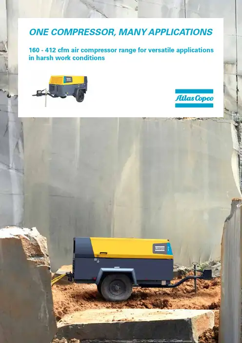
ONE COMPRESSOR, MANY APPLICATIONS 160 - 412 cfm air compressor range for versatile applications in harsh work conditionsOptions available^Skid versions (without undercarriage) available in select modelsOne range that fits a wide range of applications in the harshest of work environments! Whether for mining applications or general construction these compressors are truly versatile in performance for various applications.►Jack hammer ►Sand blasting ►Ball passing ►Road cleaning►Pneumatic chip breaking ►Pneumatic rivetting ►Pipeline services ►PiggingOur compressors are specially designed for applications such as:WIDEST RANGE OF COMPRESSORS TO SUIT MULTIPLE APPLICATIONS IN ITS CLASS** Non standard, and are available on request.TECHNICAL DATA2PATENTEDSCREWELEMENTDURABLE AND ROBUSTHOOD CANOPYBETTERACCESSTO SERVICE PARTSCOMPACTANDLIGHTWEIGHTPRODUCT FEATURESHood and gull wing designcanopy for better service accessSpecial box to keep all important documents related to compressorHeavy duty air filterFull shift fuel tank designed for 10 hours workingStrong lifting bar for frequent transportationMultiple outlet valves suitable for wide range of applicationsGood ground clearanceOperation and monitoring on the same sideHigher power to weight ratio Robust tow bar for easy towing in tough terrains and mines3/en-inSKumar:+919940686506,*********************.com,PrakashKhobragade:+919331411141,********************************.com,FenilShah:+917030464386,********************************************@Tollfreenumber180********Photos and illustrations contained herein might depict products with optional and/or extra components which are not included with the standard version of the product and, therefore, are not included in a purchase of such product unless the customer specifically purchases such optional/extra components. We reserve the right to change the specifications and design of products described in this literature without notice. Not all products are available in all markets.PORTABLE ENERGY SOLUTIONS PORTFOLIOMOBILE• 9-1250* kVAINDUSTRIAL • 10-1250* kVAGENERATORSPORTABLE• 60-80-100 kVAAIR COMPRESSORSPRODUCTIVITY PARTNER• 1000-1350 cfm • 19-35 barDEWATERING PUMPSELECTRICSUBMERSIBLE • 275-16.500 l/minDIESEL DRIVEN CANOPY• 833-9833 l/minDIESEL DRIVEN OPEN FRAME • 3300-7500 l/minLIGHT TOWERSLEDMETAL HALIDEELECTRICREADY TO GO • 160-412 cfm • 7-8.5 barVERSATILITY • 436-675 cfm • 10.5-20 bar*Multiple configurations available to produce power for any size application.Diesel and electric options available.Diesel and electric options available.L A P W S I Z E 1R © 2017 A t l a s C o p c o P o r t a b l e E n e r g y A l l r i g h t s r e s e r v e d .® A t l a s C o p c o i s a r e g i s t e r e d t r a d e m a r k o f A t l a s C o p c o A B。
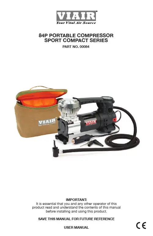
Please read this instruction manual carefully prior to operating this product.Pay particular attention to the CAUTION and WARNING statements in this manual. Failure to comply with these instructions could result in personal injury or property damage. Retain these instructions for future reference.DESCRIPTION:This portable oil-less air compressor is designed to operate on 12 volts DC and must be plugged into a cigarette lighter power port to operate. The unit comes equipped with a pressure gauge and a 3 pc. set of inflation tips. It can be used for inflating tires, sports balls, or topping off pressure for single person tube rafts, air mats, and other uses.84P AMP DRAW WARNING:Most automotive cigarette lighter/power ports handle up to 15 amps. Some vehicles’ power ports may have even lower amp ratings. Before purchasing and using this unit, inspect the amp draw limitations of your vehicle’s power port. The 84P Portable Air Compressor requires a power port rated for 15 amps. Never replace fuses of higher amp rating beyond the original rating of the circuit. Consult your vehicle’s manual for further details.IMPORTANT SAFETY INSTRUCTIONS:CAUTION: The compressor has been designed to provide long-term, trouble-free operation.To reduce risk of electrical shock or electrocution and to prevent damage to your compressor, follow these simple guidelines:1. Do not disassemble. Do not attempt to repair or modify this unit.2. Never allow children to operate this compressor. Close supervision is necessary whenthis compressor is being used near children.3. This compressor will become very hot during and immediately after use.4. Do not touch any part of this compressor with bare hands, other than the ON/OFF switchand carry handle, during or immediately after use.5. Provide sufficient cooling time before storing the unit.6. Never operate the compressor near fire, flammable gas or liquid.7. There are no user-serviceable parts in this unit, no lubrication is required.8. Do not pump anything other than atmospheric air.9. Never use this product while sleepy or drowsy.10. B e sure the unit’s power switch is in the OFF position when not in use.11. U se only in well ventilated areas.12. T he unit should be used only in dry environment. Protect the unit from rain, snow orother sources of moisture.13. N ever carry the air compressor by the hose or power cord.14. Never point air nozzle towards another person or any part of the body.15. Inflate items only to their manufacturer’s recommended pressure.16. Do not leave air compressor running unattended. It could burst tires or other items.FEATURES:1. Built-In 100 PSI Pressure Gauge2. LED Work Light/Power Indicator3. Accessory Power Plug4. Deluxe Carry Bag with Bright Orange Lining for Enhanced Visibility5. 3-Pc. Inflation Tips Kit6. Oil-Less Design7. Gearless Direct-Drive Motor8. Permanently Lubricated Bearings9. Compact Size for Easy Carrying and Storage10. P ress-On Tire Chuck11. P ower cord: 10 ft. / Air Hose: 3 ft.OPERATING INSTRUCTIONS:IMPORTANT: Engine MUST be running while using this compressor.Before attaching air compressor’s power cord to power source, check to make sure that theON/OFF switch of your compressor is in the OFF position.CAUTION: Your Portable Air Compressor is Moisture and Dust Resistant, but NOT WATER OR DUST PROOF. Never place compressor in soft sand while running the compressor. Vibration from the compressor will cause the compressor to settle into soft sand, resulting in compressor drawing in foreign particles. Never expose compressor to water while running the compressor.TIRE INFLATION:1. This compressor is designed to operate on 12 volts DC.2. To obtain power, plug into a vehicle accessory power port.3. Turn your vehicle engine on.4. Attach the press-on air chuck to the tire’s valve stem.5. Turn the compressor power switch to ON and begin to inflate tire.6. When the pressure gauge indicates the desired pressure, switch the unit OFF andremove the air hose from the tire’s valve stem.7. To check and verify the actual tire pressure, the compressor must be in the OFF position. Please Note: During inflation, due to air velocity, pressure gauge cannot provide accurate pressure readings, to check and verify the actual tire pressure the compressor must be in OFF position. CAUTION: To avoid over inflation, never exceed recommended pressure. Doing so may cause articles to burst and can cause serious bodily injury. Always make sure the Portable Compressor’s power cord is uncoiled and fully extended when using your air compressor to avoid overheating the power cord.FOR ALL OTHER INFLATABLE OBJECTS, INCLUDINGBICYCLE TIRES, TOYS, AND SPORTS BALLS:IMPORTANT: Engine MUST be running while using this compressor.1. A selection of inflation tips is provided to fit some inflatable objects.Simply clamp the appropriate nozzle into the press-on tire chuck of the air hose.2. Attach the appropriate nozzle to article to be inflated and turn the power switchto the ON position.3. When article is inflated to desired firmness, turn the compressor off. Do not over inflate.。
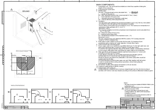
EdPosi-tionModified fromDateIntr./Appd.123456789A10BCDEFGParent 3D modelEd . Version 3DC O N F IDE N T I A L :T h i s d o c u m e n t i s o u r p r o p e r t y a n d s h a l l n o t w i t h o u t o u r p u r p e r m i s s i o n b e a l t e r e d ,c o p i e d , u s e d f o r m a n u f a c t u r i n g o r c o m m u n i c a t e d t o a n y o t h e r p e r s o n o r c o m p a n y03Ceiling height & Note added2013-04-08 982069500101.00 P x d x P450 x Qc51.85MAIN COMPONENTS1. Compressor unit : The unit should be installed on a level floor capable of taking the weight of the compressor.2. Compressed air outlet valve.3. Delivery pipe : The max . total pipe length can be calculated from L = L = Length of the pipe (m)P = Max. allowable pressure drop (recommended 0.1 bar (1.5psi)) d = Inner diameter of the pipe (mm)P = Absolute pressure at compressor outlet (bar) Qc = Free air delivery of the compressor (l/s)4. Ventilation :The inlet grid(s) and ventilation fan should be installed in such a way that any recirculation of cooling air to the inlet grating of the compressor is avoided.The air velocity to the grid(s) has to be limited to 5 m/s. The maximum air temperature at compressor intake opening is 46 C, min 0 C. Alternative 1 and 3 :The required ventilation to limit the compressor room temperature can be calculated from : Qv = 1.19 N / TQv = Required cooling air flow (m /s) N = Nominal motor power (kW)T = Temperature increase in the compressor room. ( C) Alternative 2 and 4 :The max. pressure drop over additional AIR/OIL coolers ("10") ducting should be limited to 10 Pa for standard fans.5. Drain pipes to drain collector must not dip into the water. For draining of pure condensate water, install an oil / water seperator. Consult Atlas Copco.6. Control cubicle with monitoring panel.7. Power supply cable to be installed by a qualified electrician. For the right cable size, see Atlas Copco technical data. In case of IT network, consult Atlas Copco.To preserve the ingress protection rating of the electric cubicle, it is absolutely necessary to use a proper cable gland when connecting the supply cable to the compressor.8. Filter type DD for general purpose filtration (particle removal down to 1 micron with a maximum oil carry over of 0.5 ppm).A high efficiency PD filter may be installed downstream the DD filter (particle removal down to 0.01 micron and max. oil carry over of 0.01ppm)Should oil vapours and odours be undesirable, a QD active carbon filter should be installed after the PD filter.It is recommended to install by-pass pipes over each filter together with ball valves in order to isolate the filters during service operations, without interrupting the compressed air delivery.9. Air receiver: A safety valve need to be foreseen on the air receiver.10. Cooling air outlet grating of AIR/OIL coolers.11. Ceiling height with ducting (h);Ceiling should be considered with a minimum straight length duct from the hot air exhaustand then a 90 bend or main duct header according to the pressure differential limitations given.Fini wt.Approved.TreatmentMaterial Name Drawn byDes checked.Scale Blank wt .Prod checked.FamilyBlank nr.KgDesignation SheetINVReplacesCompare DateDrawing owner/Confidentiality Class STATUSTolerances, if not indicated, according to:A1Not Applicable 1114/03/200598206950010N/AInternalNot ApplicableApproved InternaldavinciAPIacc. to 1102 KDIMENS. INSTALL.Drawing format Notes :- All pipes should be installed STRESS FREE to the compressor unit.- Maximum allowable force on the outlet pipe should not exceed 100N.- For more information concerning air nets, cooling systems, etc refer to the compressor installation manual.- For dimensions and air flow directions refer to the AIB dimension drawings.VENTILATION PROPOSALSALT. 1ALT. 2ALT. 3ALT. 42345678800500800200610630Minimum free area to be reserved for the compressor installationControllerA l l m a t e r i a l s s u p p l i e d a r e i n c o m p l i a n c e w i t h t h e r e q u i r e m e n t s o f t h e L i s t o f P r o h i b i t e d S u b s t a n c e s333Min. 800 without ducting (h)CEILINGATLAS COPCO STANDARD CLASS -/-。

COMMERCIAL REFRIGERATION COMPRESSORS180****1700************************/IndiaEmerson and Copeland are trademarks of Emerson Electric Co. or one of its affiliated companies. ©2018 Emerson Climate Technologies Inc. All rights reserved.A S I A 10-B 0303-R 01-07/2018REGISTERED HEAD OFFICEEmerson Climate Technologies (India) Pvt. Ltd.Plot No. 23, Rajiv Gandhi Infotech Park, Phase - II, Hinjewadi, Pune-411 057Tel: (91-20) 4200 2000MumbaiEmerson Climate Technologies (India) Ltd.Delphi B-Wing, 601-602, th 6Floor, Central Avenue,Hiranandani Business Park, Powai,Mumbai- 400076Tel: (91-22) 6662 0566Pvt. SecunderabadEmerson Climate Technologies (India) Ltd.C/o Maruthi Corporate Point,nd Swapnalok Complex 2 Floor, Block -B , Sarojinidevi Road, Secunderabad-500003 Tel: (91-40) 3315 4018Pvt. SALES OFFICES:GurgaonEmerson Climate Technologies (India) Private Ltd.th 18 Floor, Tower B, Building No. 5,Epitome, DLF Cyber City,Phase - III, Gurgaon 120 002Tel: (91-124) 489 4500CONTACTS LISTEmerson Commercial & Residential Solutions SecunderabadEmerson Climate Technologies (India) Pvt. Ltd.C/o: Agility Logistics Pvt. Ltd, # 8-122,Devaryamjal Road, Kompally, Shameerpet Mandal, Ranga Reddy Dist.,Secunderabad-500014,Tel: (91) 9247000174/9000649871ChandigarhEmerson Climate Technologies (India) Pvt. Ltd. C/O Agility Logistics Pvt LtdKhata No-694/712 Village–Pabhat MC Zirakpur, District – SAS Nagar Mohali, Punjab-140603Tel: 8054001380HowrahEmerson Climate Technologies (India) Ltd.C/o Agility Logistics Pvt. Ltd., Sankrail Industrial PARK,Mauza-Kandua, Bhagabatipur, Po-Kandua Howrah-711 302 Tel: +919093970556Pvt. New DelhiEmerson Climate Technologies (India) Ltd.56, Rama Road Industrial Area,Nr. Mahindra Showroom,New Delhi-110 015Tel: (91-11) 45751000Pvt. BengaluruEmerson Climate Technologies (India) Ltd. C/o Agility Logistics Pvt. Ltd., Shed No. 8, Survey No. 31, th 18 KM old Madras Road,Virgonagar, Bengaluru-560 049 Tel: +918970772593Pvt. GurgaonEmerson Climate Technologies (India) Ltd.C/o Agility Logistics Pvt. Ltd.,Khasra No.9/7/2,7/3 Min,8/1 Min, 8/2, 8/3, Off. Revenue Estate Of Village Gadoli Khurd, Sector-37 B, Pataudi Road,Gadoli Khurd (Gurgaon)-122 001 Tel: +919013774070Pvt. MumbaiEmerson Climate Technologies (India) Ltd.Unit No. 59, Ground Floor, ‘AA’ Wing,Building No.1, at Kailas Industrial complex, CTS No. 1/7 & 1/11, Veer Savarkar Marg, Near Hiranandani Park,Vikhroli (West), Mumbai-400 079 Tel: (91-22) 4270 8001Pvt. WAREHOUSES:AhmedabadEmerson Climate Technologies (India) Ltd.C/o Agility Logistics Pvt. Ltd.,Plot No. 796, Corporate Warehouse Hub,Opp. Hotel ALFA, National Highway No. 8, Aslali, Ahmedabad-382 427 Tel: 079-30924722Pvt. ChennaiEmerson Climate Technologies (India) Ltd.C/o. Agility Logistics Pvt Ltd.,Kanishk Warehouse, Sr. No. 204,Vijayanallur Village Road, Nallur Village,Cholovaram Po, Ponneri Tk, Chennai-600067.Tel: +918939571199Pvt. LucknowEmerson Climate Technologies (India) Ltd.C/o Agility Logistics Pvt. Ltd., C-522, Maya Bhagwan Complex,Near Shaheed Path Road, Transport Nagar, Lucknow-226 008 Tel: +919044225771Pvt. PLANTAtit Pali Road, Atit - 415 519, Maharashtra.Tel: (91-2162) 224200, Fax: (91-2162) 262069COLD CHAIN CENTERS Emerson Climate Technologies (India) Pvt. Ltd.Plot No. G-8/3, Block M.I.D.C. Chakan Industrial Area, Phase - III, Taluka : Khed. Dist : Pune - 410 501 Tel: (91- 2135) 625300ChakanEmerson Climate Technologies (India) Pvt. Ltd.Plot No. 127,Udyog Vihar, Phase IV,Gurgaon - 122 015, Haryana Tel: (91 124) 2866600GurgaonHeadquarters in St. Louis, Mo.200 Manufacturing LocationsFeatured in the Fortune 500 list ofAmerica's Largest Corporations by revenueManufacturing Plant at Atit, IndiaPsychrometric Lab Facility at Karad, India per fect cooling, creating value for its users.The compressors are manufactured at a state-of-the-art India plant located at Atit, in Maharashtra.The performance of the compressors is optimized using Computer Aided Engineering facilities with the components being subjected to stringent Emerson qualification standards. Additionally the compressor performance is validated by testing in a suitable appliance 0 at an ambient of 46C.The countrywide sales and service network of Emerson is geared to provide prompt after sales service to our customers.Emerson is a global technology and engineering company providing innovative solutions for customers in industrial, commercial, and residential markets. Our Emerson Commercial and Residential Solutions business helps ensure human comfort and health, protect food quality and safety, advance energy efficiency, and create sustainable infrastructure.Emerson provides advanced compressors, condensing units, flow control systems and electronic controls to protect food quality while enabling operators to maximize equipment uptime and increase energy efficiency.Fractional and Integral Horse Power compressors provideAbout EmersonPartner For All Your Cooling Needs With Energy Efficient And Rugged DesignsKCE to HP R22, R134a1/61/2KCJ 1 to 1 ¼ HP R22, R404AKCJ to 1HP R22, R134a,R404A¼KCN to HP R404AR134a, 1/61/2CRKQ 4 to 6HP R22M CRK6/KCM 1.3 to 3HP, R22, R134a, R404A1/2Split AC Cold RoomDisplay CabinetWater CoolerVisi CoolerDeep FreezerBulk Milk CoolerECZ 0.17 - 0.46 HP R134a, R404AFreezer on WheelsProduct Range Serving your High, Medium & Low Temp ApplicationsTOTAL NUMBER OF DIGITS IN THE*COOLING CAPACITY AT 60 Hz (IN Btu/h)FIRST TWO DIGITS IN THE*COOLING CAPACITY AT 60 Hz (IN Btu/h)KCE 444H A G B 332HECZ PRODUCT FAMILYCAPACITYNUMBERS OF DIGITS IN NOMINAL COMPRESSOR COOLING CAPACITY AT 60Hz RATING CONDITIONSCAPACITYFIRST TWO DIGITS IN NOMINAL COMPRESSOR COOLING CAPACITY AT 60Hz RATING CONDITIONSAPPLICATION L LBP C CBP H HBPREFRIGERANT E R-22G R-134a H R-290L R-404AMOTOR & PROTECTOR CODESCODE MOTOR PROTECTOR 1 STANDARD EXTERNAL 2 STANDARD INTERNAL 3 MODIFIED EXTERNAL 4 MODIFIED INTERNAL220-230V, 1PhG ECZ 4 44H 1 1 M11D0C 62R K Q M T F D XXX XXRefrigerant Identifies Code R PRefrigerant R22/R407C/R404AR410ACapacityFirst Two Digits Of Nominal Compressor Cooling Capacity At 60 Hz Rating ConditionCapacity Multiplier K : 1,000Model Series Variation Arbitrary Number Or Letter Assigned To Indicate Different Model Types Within Any One Family Series Q: CR Large; 6:CR,7: High Eff CR8: Ultra High EfficiencyIdentifierM : Optimized DesignMotor TypeSingle Phase Capacitor Run,Permanent Split CapacitorThree PhaseCode P TMotor Protection Type Internal Inherent ProtectionOne Protector, Use With Contactor (Single or Three Phase)CodeDescriptionFTypical Electrical CodesV -208-230, 1Z 220-240,1-D 380-420, 3380-460, 3M 380-420, 3-5-200-230, 31220-240V, 1-Code 50 Hz 60 HzPerformance Nominals And SpecificationsPerformance Nominals And Specifications#*These are optionalo Permitted Evaporating Temperature Range in C* Except KCN463HAG / KCJ498HAG : -6.7 to 12.8 o o** Except KCN : -37 C to -6.7 Co o C CPerformance Nominals And Specifications#Performance Table at ARI Conditions.5. Compressors with CSIR, CSCR circuit and three phase models may be usedwith thermostatic expansion valve.6. Compressors with RSIR Circuit must use capillary tube only.7.All compressors use two pole motors.8. Compressors for specific applications are rated for IS-10617 Part I andPart III-1983.9. All run capacitor should have a rating of 440 VAC and start capacitor 275VAC surge, unless otherwise specified by Emerson.1. Electrical rating is 230 V, 50 Hz and 230 V, 60 Hz for single phasemodels and, 400 V, 50 Hz for three phase models.2. Operating voltage range signifies the range of voltage for which thecompressor can start and run up to 43C ambient.3. Cooling capacity and power consumption are nominal values atspecified rating conditions and subject to +5% variation.4. Direct air flow on glass terminal cover should be avoided.NotesPerformance Nominals And SpecificationsPlease refer our separate catalogue for KCM low temperature 3 phase modelsASRE/T Rating ConditionsMedium Temperature (R134a)Operating EnvelopesHigh Temperature (R22)High Temperature (R134a)High Temperature (R134a)High Temperature (R134a)High Temperature (R22)Low Temperature (R134a)Low Temperature (R134a)Medium Temperature (R404A)Low Temperature (R404A)Low Temperature (R404A)* Contact Emerson Representative for non standard BoM.Standard BoM DataStandard BoM Data For CR CompressorKCNDimensional DrawingsKCJ423LAGKCJ412LAG 0.504/0.507 [12.80/12.88] I.D.SUCTION TUBE 0.254/0.257 [6.45/6.53] I.D.PROCESS TUBE 0.316/0.319 [8.03/8.10] I.D.DISCHARGE TUBE 1.31 [33.2]19Suction Tube (Copper)(6.43/6.50) ID (6.45/6.52) ID (Flared)(6.43/6.50) ID*Height is 215.5mm for ECZ416/417/419ECZ411, ECZ416, ECZ417, ECZ419, ECZ434, ECZ444KCM475LAL/KCM511CAL/514CAL with Suction TubeKCM475LAL/KCM511CAL/514CAL with SpudSUCTION SPUD ADAPTOR FOR 0.375 1-14 UNS-2A EARTHINGDISCHARGE TUBE 0.379/0.382[9.63/9.70]I.D.SUCTION TUBE 0.504/0.507[12.80/12.88] I.D.PROCESS TUBE 0.254/0.257[6.45/6.53] I.D.KCJ450LAL with Suction SpudKCJ450LAL with Suction Tube200.504/0.507 [12.80/12.88] I.D.SUCTION TUBE 0.254/0.257 [6.45/6.53] I.D.PROCESS TUBE 0.316/0.319 [8.03/8.10] I.D.DISCHARGE TUBEKCJ430LALKCJ444HAGSUCTION TUBE[6.15/6.53] I.D.DISCHARGE TUBEPROCESS TUBE0.254/0.257KCM519CAL/522CAL with Spud KCM522CAL with Suction TubeKCJ467HAG0.504/0.507[12.80/12.88] I.D.SUCTION TUBE0.254/0.257[6.45/6.53] I.D.PROCESS TUBE0.316/0.319[8.03/8.10] I.D.DISCHARGE TUBEEARTHINGKCJ482HAG.87[22..75[19.SUCTION TUBE (COPPER)0.504/0.507[12.80/12.88] I.D. (FLARED)PROCESS TUBE (COPPER)0.254/0.257[6.45/6.53] I.D.DISCHARGE TUBE (COPPER)0.379/0.382[9.63/9.70] I.D. (FLARED)KCM519CAL with Suction TubeKCJ498HAGSUCTION TUBE0.504/0.507[12.80/12.88] I.D.PROCESS TUBE0.254/0.257[6.45/6.53] I.D.DISCHARGE TUBE0.316/0.319[8.03/8.10] I.D.]]22KCJ513HAG]SUCTION TUBE (COPPER)0.504/0.507[12.80/12.88] I.D. (FLARED)KCJ511HAG21KCJ513HAESUCTION TUBE 0.504/0.507 [12.80/12.88] I.D.PROCESS TUBE 0.254/0.257 [6.45/6.53] I.D.DISCHARGE TUBE 0.379/0.382 [9.63/9.70] I.D.KCJ511HAESUCTION TUBE 0.504/0.507 [12.80/12.88] I.D.PROCESS TUBE 0.254/0.257 [6.45/6.53] I.D.DISCHARGE TUBE 0.316/0.319 [8.03/8.10] I.D.0.87 [22.1]SUCTION TUBEKCJ***CAL with Suction TubeSUCTIONSPUD ADAPTOR FOR 0.3751-14 UNS-2AKCJ***CAL with Suction Spud2324CR36K6MCR22K6M / CR30K6MSQUARE MOUNTSUCTION TUBE PROCESS TUBE 1/4 [6.5] IDDISCHARGE TUBE 3/8 [9.6] IDCR 47, 53, 57, 62, 72 KQMCR42K6M25Wiring DiagramsPERMANENT SPLIT CAPACITOR (PSC)CAPACITOR START INDUCTION RUN(CSIR) WITH PLUG-IN START RELAYFig. 1 Fig. 2RESISTANCE START INDUCTION RUN (RSIR) WITH PLUG-IN START RELAYCAPACITOR START CAPACITOR RUN (CSCR)Fig. 3Fig. 4CAPACITOR START INDUCTION RUN (CSIR)CAPACITOR START INDUCTION RUN (CSIR)WITH CURRENT RELAYCAPACITORFig. 5Fig. 6Wiring DiagramsCAPACITOR START CAPACITOR RUN (CSCR)WITH PTC Fig. 7CAPACITOR START CAPACITOR RUN (CSCR) WITH NTCFig. 82627ApplicationsDeep Freezer Refrigerator Ice Cube machine Walk-in Freezer Laboratory Appliance Bottle Cooler Visi-Cooler Display Cabinet Pastry Cabinet Softy IcecreamWater CoolerOil Coolers / Panel Cooler Water Chiller Refrigerated Air Dryer Walk-in Cooler Milk Cooler* These are preliminary guidelines. The actual compressor selection may differ from the guidelines. Please check the system details before selecting compressor model.Deep FreezerHard Top (Ltr)Glass Top (Ltr)300 200400 300450 300450 300 500 400 800 - 1100 - 1800-ModelKCN396LAG/ECZ396LGKCN411LAG/ECZ411LGKCJ412LAG KCN415LAG/ECZ416LGKCJ423LAG KCJ430LAL KCJ450LALKCN372LAG/ECZ380LG Model Selection Guide*Cold Room o(+4 C Room Temperature)Room Size (cft)5008001200160020002500R22 R134aKCM511CAL KCM511CAL KCM514CAL KCM519CAL KCM522CAL -R404AKCJ484CAL KCM511CAL KCM514CAL KCM514CAL KCM519CALKCM522CALKCJ513HAE CR22K6M CR30K6M CR30K6M CR36K6M CR42K6M CR53KQM CR62KQM------Water CoolerCapacityR22R134a(Ltr/Hr)20-KCE419HAG/ECZ421HG 40-KCE444HAG/ KCJ444HAG/ECZ444HG60KCE461HAE KCN463HAG/ KCJ467HAG 100KCJ511HAE KCJ498HAG/KCJ511HAG150KCJ513HAE KCJ513HAG 200KCM514CAL 300KCM522CALCR22K6M CR30K6MFreezer on Wheels28Bottle CoolerCapacity(Ltr)R22R134a100-120-KCE419HAG/ECZ421HG150-200-KCE425HAG/ KCN413CAG/ECZ426HG 220-250-KCE432HAG/KCN416CAG/ECZ431HG/ECZ434HG260-350 KCE443HAE KCE444HAG/KCJ444HAG/ECZ444HG350-500 KCE461HAE KCN463HAG/KCJ467HAG600-800 KCJ511HAEKCJ498HAGVisi-CoolerCase 2 (110 ltr)4 (150 ltr)7 (250 ltr)9 (400 ltr)12(650 ltr)ModelKCE419HAG/ECZ421HGKCE425HAG/ KCN413CAG/ECZ426HG KCE432HAG/KCN416CAG/ECZ431HG/ECZ434HGKCE444HAG/KCJ444HAG/ECZ444HGKCN463HAGFreezer on WheelsCapacity (Ltr)80 - 100-110 - 140 ECZ412LL 150 - 180ECZ417LL 200 - 300ECZ419LLR404A 0Water inlet temperature : 10C 0Water outlet temperature: 5CWater Chiller Flow Rate R22R134a R404A (Ltr/Hr)600KCM514CAL KCJ484CAL 800KCM519CAL KCM511CAL 1000KCM522CALKCM514CAL 1400-KCM519CAL 1600-KCM522CAL----KCJ513HAE CR22K6M CR30K6M CR36K6CR42K6CR53KQM CR62KQM--Softy MachineCapacity (Ltr)15 KCM511CAL 20 KCM514CAL 30 KCM519CAL 40KCM522CALR404A ECZ380LG ECZ411LG ECZ416LG -R134ASystem Practice GuideSystem CleanlinessŸIt is absolutely necessary that all impurities / contamination like moisture, burr, cleaning agent and chemicals areremoved from the system before operation in order to avoid compressor failures.ŸAll system components have to be de-hydrated and should be Nitrogen charged till they are taken for assembly. Usebright annealed refrigeration grade Copper tubes.ŸUse Try-chloro Ethylene for flushing followed by dry air or Nitrogen to remove the trace of Try-chloro Ethylene.BrazingŸWhile brazing all the joints purge low pressure Nitrogen through the tube. This will avoid internal oxidation andformation of contamination. Use adequate amount of flux while brazing.ŸThe joints have to be free from oil and grease before brazing. For Copper to Copper joints use phosphorousCopper as brazing alloy and Copper - Silver for Copper toSteel joints. Oxy Acetylene is best suited for brazing.Leak TestingŸThe system has to be adequately pressurized with dry air or Nitrogen.ŸUse of electronic leak detectors is the best way to detect leaks.ŸConventional methods of checking the leaks can also be used.ŸDo not pressurize the system with air and R134a.EvacuationEffective evacuation of the system ensures removal of moisture. For achieving desired vacuum level of 200 microns:ŸPull vacuum from both sidesŸHeat the system with bulbs or infra red lampsŸUse Copper tubes to connect the vacuum pump and the systemŸThe connecting Copper tubes have to be short in length and bigger in diameterŸUse adequately sized two stage rotary vacuum pump having anti-suckback provisionŸUse electronic vacuum gauge to measure the vacuum level ŸNever use a hermetic compressor for evacuation. It is not meant for evacuation and cannot achieve desired vacuum levelRefrigerant ChargingŸQuality and quantity of refrigerant immensely influences theperformance and reliability of any refrigeration system.ŸRefrigerant should be procured from genuine source. Usedigital weigh balance during refrigerant charging.ŸMaintain a separate set of hoses, tubes, valves for differentrefrigerants. Do not use anti-choke as it damages thecompressor.ŸUse pressure temperature chart of refrigerant for achievingoptimum system performance.Compressor MountingŸTorque the nut adequately and ensure that the washer / bolthead rest on the sleeve and not on the rubber grommet.ŸThe suction and discharge piping should be properly loopedto avoid vibrations and refrigerant leakages. The compressorshould not be held rigidly by any means.ŸThese compressors are not suitable for mobile applications.ElectricalsŸAlways check the voltage across C & R terminals. Voltage atthis point should fall within the prescribed operating voltagerange. If the supply voltage conditions are poor, useappropriately sized voltage stabilizer with low, high voltagecutout and On-delay timer.ŸAlways use genuine electrical accessories supplied byEmerson.ŸEarthing the appliance is necessary from the safety standpoint.ŸAll electrical joints have to be firm and properly insulated.Attending The Field ComplaintsŸVerify the field complaint based on facts and observationsmade through use of proper tools and equipment. Rule outall the possibilities before replacing the compressor. Analyzethe compressor independently for its proper functioning.ŸRemoving of compressor from the system withoutunderstanding the root cause will lead to anothercompressor failure.DisclaimerNoteAbout EmersonTechnical data given was correct at the time of printing. Updates may occur, and should you need confirmation of a specific value, please contactEmerson stating clearly the information required. Emerson cannot be held responsible for errors in capacities, dimensions, etc., stated herein.Products, specifications and data in this literature are subject to change without notice. The information given herein is based on data and testswhich Emerson believes to be reliable and which are in accordance with today's technical knowledge. It is intended for use by persons having theappropriate technical knowledge and skill, at their own discretion and risk. Our products are designed and adapted for fixed locations. Formobile applications, failures may occur. The suitability for this has to be assured from the plant manufacturer, which may include makingappropriate tests.The components listed in this catalogue are not released for use with caustic, poisonous or flammable substances. Emerson cannot be heldresponsible for any damage caused by using these substances.Emerson (NYSE:EMR), headquartered in St. Louis, Missouri (USA), is a global technology and engineering company providing innovativesolutions for customers in industrial, commercial, and residential markets. Our Emerson Automation Solutions business helps process, hybrid,and discrete manufacturers maximize production, protect personnel and the environment while optimizing their energy and operating costs.Our Emerson Commercial and Residential Solutions business helps ensure human comfort and health, protect food quality and safety, advanceenergy efficiency, and create sustainable infrastructure. For more information visit 3029。
目录1.0产品介绍 (3)2.0安全 (4)2.1总则 (4)2.2个人防护设备 (4)2.3压力 (4)2.4防火、防爆 (4)2.5移动及旋转机械的保护 (4)2.6危险表面 (5)2.7有害物质 (5)2.8起吊和运输 (5)2.9防止人员关闭在机器内 (5)2.10操作 (5)3.0总体描述 (5)3.1操作原理 (6)3.2控制系统 (6)3.3进气温度 (7)3.3.1 冷凝--低温 (7)3.3.2 过热--高温 (7)3.3.3 排气温度 (7)4.0 技术特性 (8)4.1 电器特性 (8)4.2润滑油特性 (8)4.2.1 电动机轴承用油 (8)5.0 安装和开机前检查 (9)5.1 位置要求 (9)5.2 散热要求 (9)5.3 对水冷却型机组,冷却水质的要求 (10)5.4 空气管道系统的连接要求 (10)5.5 电器安装要求及电器检查 (11)5.5.1 电源 (11)5.5.2 电机转向 (11)5.6机械检验 (11)5.6.1螺杆机头检查 (11)5.6.2油位检查 (12)5.6.3传动系统的检查 (12)5.6.4检查系统里所有的阀门 (12)6.0 操作 (12)6.1 开机前的准备 (12)6.2 初始开机程序 (13)6.2.1 日常开机程序 (13)6.2.2 停机程序 (13)6.3 功能控制 (14)6.3.1 标准型 (14)6.3.2智能型操作使用介绍 (14)6.4 压力开关控制 (15)6.5 高温停机 (15)6.5.1螺杆机头的高温保护 (15)6.6 电机热过载保护 (15)6.7 温控阀 (15)7.0 选项 (16)7.1 主、备机控制方式 (16)7.2 油过滤器压差显示 (16)7.3 空气过滤器压差显示 (16)7.4 油气分离筒压差显示 (16)7.5 遥控启动/停止装置 (16)7.6 加载定时器 (17)8.0 保养 (17)8.1 总则 (17)8.2日常操作 (17)8.2.1 保养计划 (17)8.2.2 运行500小时 (18)8.2.3 每3000小时 (18)8.2.4 每6000小时 (18)8.3 保养指导 (18)8.3.1 空气过滤器的保养方法 (19)8.3.2 油过滤器的保养方法 (19)8.3.3 油气分离器的保养方法 (19)8.3.4 进气控制阀的特性及保养方法 (19)8.3.5 最小压力控制阀的保养方法 (20)8.3.6 润滑油的更换方法 (20)8.3.7 油位 (20)8.3.8 皮带松紧度的调整方法 (20)8.3.9 更换皮带方法 (21)8.3.11膜片联轴器的对中 (21)8.3.12 电动机的保养方法 (21)8.4 故障排除表 (22)附页:智能型控制系统 (23)标准型电气原理图1.0产品介绍施耐德日盛螺杆式空气压缩机结构设计独特,具有结构紧凑、外型别致、效率高、能耗小、噪音低和使用寿命长等特点,属智能环保型产品。
/igfgCompact, lightweight designHigh tensile extruded aluminium columns and manifolds reduce the footprint of the dryer, allowing for easy installation and maintenance. Fully corrosion protected inside and out and covered by a 10 year guarantee on the pressure envelope.International approval standards Due to the column design, MX is exempt from the pressure vessel inspection requirements of ASME meaning the elimination of costly annual checks. MX is also fully compliant with PED/ CSA/UL/CRN approvals.Consistent dewpoint performance-40°F and -100°F dewpoint models will inhibit the growth of micro-organisms as well as eliminate downstream corrosion. Snowstorm desiccant filling provides 100% utilization of the dryer bed, preventing air channelling, significantly reducing attrition which could lead to blocked filters and loss of dewpoint.Low operational noise levels of <75 db (A) helps to support a safe working environment. Flexible control optionsMXSmart offers users flexibility and additional advanced features in electrical operation to meet plant requirements. MXP models provide ATEX Group II, category 2GD, T6 approved pneumatic control.Energy Saving Technology (DDS)This option automatically adapts dryer operation to the ambient inlet conditions and compressed air demand, ensuring optimum energy consumption and full utilization of the desiccant material. Compressor synchronizationWhen the dryer is installed prior to the air receiver, MX can provide a purge economy feature that prevents the dryer from carrying out its regeneration cycle when the compressor goes off load. This saves energy and money with the elimination of the use of unnecessary purge air. Normal drying cycles automatically resumes once the compressor re-starts.MODULAR CONSTRUCTION Allows greater flexibility, dryers can be multi-banked to provide extra compressed air drying capacity should demand increase. This feature allows 100% standby at a fraction of the cost of alternative construction methods and also allows individual dryers to be easily isolated for routine service work, while maintaining the plant’s clean, dry air supply.Parker MX heatless regeneration compressed air dryer. Innovative engineering and technology.Providing clean, dry compressed air in accordance with all editions of ISO8573-1, the international standard for compressed air quality.MX HEATLESSCOMPRESSED AIR DRYERFlow RatesDryer SelectionTo correctly select a dryer model, the flow rate of the dryer must be adjusted for the minimum operating pressure and, maximum operational temperature of the system. If the dewpoint required is different to the standard dewpoint of the dryer then the flow rate must also be adjusted for the required outlet dewpoint.1. Obtain the minimum operating pressure, maximum inlet temperature and maximum compressed air flow rate at the inlet of the dryer. Obtain the outlet dewpoint required.2. Select correction factor for maximum inlet temperature from the CFT Table (always round up e.g. for 107°F use 113°F correction factor)3. Select correction factor for minimum inlet pressure from the CFP table (always round down e.g. for 92 psi use 87 psi correction factor)4. Select correction factor for required outlet dewpoint from the CFD table5. Calculate minimum drying capacityMinimum Drying Capacity = Compressed Air Flow x CFT x CFP x CFD6. Using the minimum drying capacity, select a dryer model from the flow rate tables above (dryer selected must have a flow rate equal to or greater than the minimum drying capacity) If the minimum drying capacity exceeds the maximum values of the models shown within the tables, please contact Parker for advice regarding larger multi-banked dryers.Stated flows are for operation at 7 bar g (100 psi g) with reference to 68°F (20°C), 14.5 psia (1 bar a), 0% relative water vapor pressure. For flows at other pressures apply the correction factors shown.Product SelectionTechnical DataDryer Performance= S (Smart) / P (Pneumatic)Controller OptionsWeights and Dimensions= S (Smart) / P (Pneumatic)Adsorption dryers are designed to remove water vapor from compressed air. For optimum performance and to deliver air quality in accordance with all editions of ISO8573-1, liquid water, oil and solid particulate must be first be removed using Parker domnick hunter OIL-X Grade AOP , AAP filters. Grade AOP filters (with manual drain) should also be fitted to the outlet of the dryer for solid particulate removal.Recommended Filtration= G (BSPP) / N (NPT)= S (Smart) / P (Pneumatic)Parker Hannifin CorporationIndustrial Gas Filtration and Generation Division 4087 Walden Avenue Lancaster, NY 14086phone 800 343 /igfg© 2019 Parker Hannifin Corporation. Product names are trademarks or registered trademarks of their respective companies BUL_PKR_PNEUDRIMX_US_052019Worldwide Filtration Manufacturing LocationsNorth AmericaCompressed Air TreatmentIndustrial Gas Filtration and Generation DivisionLancaster, NY 716 686 6400/igfg Haverhill, MA 978 858 0505/igfgEngine FiltrationRacorModesto, CA 209 521 7860/racor Holly Springs, MS 662 252 2656/racorHydraulic FiltrationHydraulic & Fuel FiltrationMetamora, OH 419 644 4311/hydraulicfilter Laval, QC Canada 450 629 9594 VelconColorado Springs, CO 719 531 5855 Process Filtrationdomnick hunter Process Filtration SciLogOxnard, CA 805 604 3400/processfiltrationWater PurificationVillage Marine, Sea Recovery, Horizon Reverse OsmosisCarson, CA 310 637 3400/watermakersEuropeCompressed Air Treatmentdomnick hunter Filtration & SeparationGateshead, England +44 (0) 191 402 9000 /dhfnsParker Gas SeparationsEtten-Leur, Netherlands +31 76 508 5300/dhfnsHiross AirtekEssen, Germany +49 2054 9340/hzfd Padova, Italy+39 049 9712 111 /hzfdEngine Filtration & Water PurificationRacorDewsbury, England +44 (0) 1924 487 000 /rfdeRacor Research & DevelopmentStuttgart, Germany+49 (0)711 7071 290-10Hydraulic FiltrationHydraulic FilterArnhem, Holland +31 26 3760376 /hfde Urjala, Finland+358 20 753 2500Condition Monitoring Parker KittiwakeWest Sussex, England +44 (0) 1903 731 470 Process Filtrationdomnick hunter Process Filtration Parker Twin Filter BVBirtley, England+44 (0) 191 410 5121/processfiltrationAsia PacificAustraliaCastle Hill, Australia +61 2 9634 7777/australiaChinaShanghai, China +86 21 5031 2525 /chinaIndiaChennai, India +91 22 4391 0700 /indiaParker FowlerBangalore, India +91 80 2783 6794JapanTokyo, Japan +81 45 870 1522/japanKoreaHwaseon-City +82 31 359 0852/koreaSingaporeJurong Town, Singapore +65 6887 6300/singaporeThailandBangkok, Thailand +66 2186 7000/thailandLatin AmericaParker Comercio Ltda. Filtration DivisionSao Paulo, Brazil +55 12 4009 3500 /brPan American DivisionMiami, FL 305 470 8800/panamAfricaAeroport Kempton Park, South Africa +27 11 9610700/africa。
PISTON COMPRESSOR MANUAL REV022621Contents Safety Information 2-3 Breathable Air 3Pressurized Components 3Personal Protective Equipment 3 Nomenclature 4 Features and Extras 5-7 Pump Riser 5Belt Tensioner 5Continuous Run 6Automatic Tank Drain 7 Installation 8-16 Area 8Lifting and Movement 9General Lifting 9Anchoring 10Electrical 11-14 Piping 15-16 Pre-use Inspection 17 Operation 18Pump Times 18 Maintenance 19-20 Maintenance Schedule 19-20 Oil Change/Selection 20Oil Disposal 20 FAQ and Troubleshooting 21 Warranty Information 22-24SAFTEY INFORMATIONThis manual contains very important information to know and understand. This is to provide for SAFTEY and to PREVENT EQUIPMENT PROBLEMS. To help understand this information, observe the following:DANGER:Danger indicates and imminently hazardous situation which, if not avoided, will result in death or serious injury.WARNING: Warning indicates a potentially hazardous situation which if not avoided, could result in death or serious injury.CAUTION:Caution indicates a potentially hazardous situation which, if not avoided, may result in minor or moderate injury.NOTICE:Notice indicates important information, that if not followed, may cause damage to equipment.CALIFORNIA PROPOSITION 65WARNING:This product or its power cord may contain chemicals known to the state of California to cause cancer and birth defects or other reproductive harm. Wash hands after handling.1.Allow only trained, authorized persons who have read and understood these operating instructions to use thisequipment. Failure to follow the instructions, procedures and safety precautions in this manual can result inaccidents and injuries.2.NEVER start or operate the compressor under unsafe conditions. Tag the compressor, disconnect,and lock out all power to it to prevent accidental start-up until the condition is corrected.3.Install, use, and operate the compressor only in full compliance with all pertinent OSHAregulations and all applicable Federal, State & Local codes, standards, and regulations.4.NEVER modify the compressor and/or controls in any way.5.Keep a first aid kit in a convenient place. Seek medical assistance promptly in case of injury. Avoidinfection by caring for any small cuts and burns promptly.BREATHABLE AIR1.NEVER use air from this compressor for breathable air except in full compliance with OSHA Standards 29CFR 1910 and any other Federal, State or Local codes or regulations.2.DO NOT use airline anti-icer systems in air lines supplying respirators or other equipment used to producebreathable air. DO NOT discharge air from these systems in unventilated or other confined areas.Pressurized ComponentsThis equipment is supplied with an ASME designed and rated pressure vesselprotected by an ASME rated relief valve. Pull the ring before each use toensure the valve is functional. DO NOTattempt to open the valve while themachine is under pressure. See figure on the right.Personal Protective EquipmentBe sure all Be sure all operators and others around the compressor and its controls comply with all applicable OSHA, Federal, State and Local regulations, codes, and standards relating to personal protective equipment. This includes respiratory protective equipment, protection for the extremities, protective clothing, protective shields and barriers, electrical protective equipment, and personal hearing protective equipment.NomenclatureFeatures and ExtrasCompressors come in many shapes and sizes. Our units have several features that may or may not be present on your unit. These features may be purchased after the fact in kit form. This guide will explain the use and benefit of these features.Pump RiserBelt TensionerContinuous RunContinuous run allows the pump to turn continuously, hence the name. In this mode the unit pumps up to 140 PSI and then the valves are held close. This allows the pump to enter a free spin state where the unit is pulling in cold air and the simply cycling it back to atmosphere. This has several benefits:1.The pump is cooled during the free spin state since it has no pump load on it.2.Increased recovery time since the function cycles between 100 and 140 PSI; which is the optimal CFMwindow for the unit.3.Wear on your motor is decreased (especially single-phase units) as the unit is already in motion and will notneed the large amp draw to overcome zero movement and fight tank compression.4.Continuous run is best used in applications where CFM cannot be lost. Some examples of this are: mediablasting, painting, and prolonged grinding or resurfacing.Auto DrainAuto drains are preset timer valves that allow tank moisture to be vented as long as they are powered. The enemy of every compressor/air system is moisture. The auto drain removes some of the hassle of this by allowing the user to set a timer and walk away from the unit with the piece of mind that their system is protected.1. The drain works off a conventional 120V outlet.2. Timer has built in intervals that can be customized to the user need.3. Has a manual shut off for service and maintenance.4. The drain filter MUST be cleaned weekly to prevent drain blockage.5.Drain time knob, marked as ON:SEC , corresponds to how long the drain will run for when it comes on. This is listed in seconds.6. Drain interval knob, marked as OFF: MIN , corresponds to how long between cycles. Or how long the drainwill be OFF before it comes on again.7. The drain attaches to a ½” NPT female connection.8. The vent can blow to atmosphere; however, the drain is supplied with a drain silencer system which can beused to muffle the sound of the unit draining. This screws into the atmospheric vent location, however, it is not necessary for operation.9.A drain system can also be equipped by the user to allow moisture to drain to a separate location.10. The drain is also equipped with a test button to check function.InstallationArea1.Install compressor in a clean, dry, and well-lit area. Be sure installation area can maintain a temperaturerange between 35˚ - 110˚F.2.Allow sufficient space around the compressor for maintenance access and adequate airflow. Mount unit withthe belt guard (pulley and flywheel) side to the wall and leave a minimum of 15 inches of clearance.3.If acid is used in operating environment or air is dust laden, pipe intake to outside fresh air. Increase pipe sizeby 1/8”’ for every 20ft of run. Be sure to install a protective hood at the outside air intake location to prevent debris and foreign objects from blocking the intake pipe.4.In operating environments where excessive water, oil, dirt, acid, or alkaline fumes are present, a TEFC (totallyenclosed, fan cooled) motor is highly recommended. Check nameplates for motor type.5.Insulate cold water or tother low temperature pipes that pass overhead to avoid condensation dripping onthe compressor.6.In environments where fine dust is common such as granite, marble, or concrete plants the unit must beinstalled in a separate room with its own dedicated ventilation system.7.The unit can be stored outside under the following guidelines: It must be in a covered area out of extremeweather with no ability for moisture to get to the unit, it is also highly recommended that the unit is out of direct sunlight as it can fade and/or damage the coating on the unit. Direct sunlight may also interfere with safety decals on the unit.8.If the unit is in an enclosed space it requires proper ventilation as the ambient air temp where thecompressor is located CANNOT exceed 115 degrees F.e shims to level the compressor if installation area is not flat. This will help prevent excessive vibration andpremature pump wear.Lifting and Movement/Forklift1. Make sure lift operator stays aware while moving the compressor.2. Be sure to uncrate the compressor prior to movement. This will allow a visual reference for the balance ofthe unit.3. Be sure the load is secure and well balanced before moving the compressor.4. Make sure the forks are fully engaged and level prior to lifting or moving the unit.5. Keep the unit/load as low as possible while moving and refrain from quick changes in direction.6. For all other forklift safety standards/regulations please reference OSHA 1910.178- Powered industrialtrucks.General Lifting Information1. Carefully inspect all lifting equipment and ensure it is in good condition. Rated capacity of lifting equipmentmust exceed compressor weight. NEVER lift with under sized or damaged equipment.2. If using lifting equipment, ensure all lifting points are in good condition and tighten any loose nuts or boltsbefore lifting.3. A sling MUST be used when moving the compressor with a helicopter or other airborne equipment. Be sureto follow OSHA standards 1910 subpart N.4. Use guide ropes or equivalent to prevent twisting or swinging of the compressor while it is in the air andNEVER attempt to lift the unit in high winds. Keep compressor as low to the ground as possible.5. Keep all persons away from the compressor when it is lifted. DO NOT allow persons under the compressorwhile it is being lifted.6. DO NOT use bolts or other hooks on individual components to move the compressor.7. When moving and or placing the compressor ensure it is on/across a surface that can hold the combinedweight of the compressor and the loading equipment.AnchoringTo ensure proper and safe operation of the compressor the unit is required to be anchored to a flat, smooth,concrete floor. Compressors are also required to be on ¼ inch (6.35mm) MAXIMUM thick rubber anti-vibration pads.Recommended anchor Bolt specifications: wedge anchors; 3/8 in width by 3.5 in length.How to Anchor the Compressor1. Make sure the compressor is in the desired location and the anti-vibration pads are under the feet of thecompressor.2. Using the holes in the feet as guides, drill the holes for the anchor bolts through the vibration pads and intothe concrete.3. Thoroughly clean each hole.4. Put the Washer and Nut into place, make sure the top of the Nut is flush with the top of the anchor bolt, theninsert the anchor bolt into the hole.5. Hammer or mallet the anchor bolt down into the hole.6. Tighten each nut clockwise , DO NOTover tighten. DO NOTuse an impact to tighten the anchors.Electrical Safety1. Follow all NEC and local codes for electrical wiring. Allow only authorized service personnel or certifiedelectricians to install electrical components.2. Put unit on a dedicated circuit and make sure no other electrical equipment is wired into it. Failure to wireunit on an independent circuit can cause circuit overload and/or imbalance in motor phasing. Install proper No Fuse Breaker (NFB) according to the chart listed below. You may also reference NEC and local codes for additional support.3. Ensure incoming service has adequate ampere rating.4. Do not used mixed wire sizes when wiring the unit.5. The unit must be properly grounded. DO NOT connect ground to air or cooling lines.Wiring the Compressor1. Voltage should not vary more than 12% to ensure proper operation of the compressor.2. Wire size and breaker requirements for single phase units:**3. Wire size and breaker requirements for 3 phase units:**Wire size distances are from unit to the panel where the breaker is housed.**CAUTION: Under sizing wires and/or breakers can cause damage to the unit, possible injury to personnel, and void your warranty.4. Single phase unit, NO magnetic starter:5.Single phase unit WITH magnetic starter:6.Three phase unit wire diagram (Three phase will ALWAYS have magnetic starter):7.During initial start up of 3 phase unit, pay attention to flywheel rotation. When facing the front of thecompressor (Pressure switch/pressure gauge side) rotation should be clockwise. If rotation iscounterclockwise, switch incoming power leads at 3L2 and 5L3 (ensure power is off at the breaker before attempting any changes).Piping (Safety steps)1.Install appropriate flow-limiting valves as necessary according to pipe size(s) used and run lengths. This willreduce pressure in case of hose failure, per OSHA Standard 29 CFR 1926.302(b)(7).2.Flow-limiting valve are listed by pipe size and rated CFM. Select appropriate valves according tomanufacturer’s recommendations.e a flexible connector between compressor tank and dryer/piping system to minimize noise, vibration,pump wear, and to prevent damage to the unit or piping system.4.Install ASME code safety valves and ensure piping system is equipped with adequate condensate drains.5.Minimum pipe size for compressed air lines: (Pipe sizes are shown in inches)PISTON COMPRESSOR MANUAL REV0226216.Air systems should be checked daily for leaks. This helps to prevent unnecessary load on the compressor andhelps increase energy savings.7.Examples of air systems:Closed loop system. Install tee fitting in piping from air to minimize pressuredrop and to allow air flow in two directions.Air DropAir Drop: Install tee fitting withbranch to top to minimizecondensation.From CompressorElevation View8.Make sure any tube, pipe, fitting, or hose connected to the unit can withstand operating temperatures andretain pressure.9.Never use reducers in discharge piping. Keep all piping and fittings the same size in the piping system.WARNING: Never use plastic (PVC) pipe for compressed air. Serious injury ordeath could result. Piping MUST have a pressure rating of 200 PSI or greater.Pre-Use Inspection1. The unit is shipped with pump break-in oil and should be ready to operate. Be sure to check for proper oil levelbefore running the compressor. Break in oil should be change after 100 Hours of operation (active pumping time). See maintenance section for more information on oil changes and frequency.2. Check for proper belt tension. There should be ½ inch of belt slack/deflection. Refer to maintenance section ifadjustment is necessary.3. Inspect belts for frays or unit for an excess buildup of black rubber dust indicating belt wear.4. Check proper operation of all pop off safety valves on unit. Pull rings on valves to ensure they move and are freeof any obstructions. DO NOT pull the safety valve on the tank if there is air in the tank!5. Inspect all air lines/piping for proper for secure fit and corrosion or line degradation. DO NOT operate thecompressor with damaged lines. DO NOT use damaged or cracked air lines as a rupture could result in damage/injury to personnel or property.6. WITH UNIT LOCKED OUT (power off at source i,e. the electrical panel/disconnect) ensure all electrical wiring,including all terminals, are in good condition and are free of buildup, fraying, cracks or discoloration replace as needed. Check tightness of bolts securing wiring in place.7. Ensure unit is secured in place and has not shifted. Verify anchor bolts are in place and are in good condition. 8. Remove any loose items from around/on compressor to avoid damage to the unit. Examples would be looseclothing items, rags, papers, bottles, or any item that may have been placed on the unit. 9. Check unit for any oil leaks. If leaks are found contact manufacturer for further instructions. 10. Unit should NEVER be operated without the belt guard in place.11. Inspect Flywheel for cracks or missing fins. NEVER operate a unit with a damaged flywheel; serious injury ordeath could result. If you suspect your flywheel may have been damaged, contact technical assistance and DO NOT allow the machine to be operated.Ensure all personnel that work around or operate the compressor have read this manual and are well versed in the operation of this machinery. NEVER allow untrained personnel to operate this unit.1. Once the inspection is completed, open your discharge port (outlet ball valve). This should already be connectedto your shop airline system.2. Ensure all personnel are clear of the compressor and aware that it is being started.3. Turn the selector on your pressure switch to AUTO. This will start your compressor and allow it to fill. The tankwill fill to 175 PSI, and unless otherwise noted, will shut off. The unit will begin pumping again once the tank is drained down to approximately 135 PSI. ***This may vary based on features, if your unit is equipped withCONTINOUS RUN , the unit may perform differently then specified in this step. (Check the FEATURES section for more information)4. Oil pressure on start up will vary due to ambient temperatures but should not exceed 100 PSI. Once the unit isallowed to run a few cycles and come to optimal operating temperature, oil pressure should stabilize at 20-35 PSI. If the oil pressure remains high or drops too low, it can be adjusted as follows:Pump Up Time (General)Compressor maintenance must be performed as described in the maintenance schedule, failure to do may lead to compressor/component breakdown and void compressor warranty.Maintenance ScheduleThe table below is a generalized maintenance schedule based on the normal usage of a compressor. Your specific needs may vary based on operating environment and duty.Frequency of these changes are a generalization and may be subject to change based on compressor environment, hours, and application.Oil ChoiceIt is strongly advised to use only Airbase Industries piston compressor oil. Check with your warranty/extended warranty guidelines to verify oil selection and use. Oil used in the compressor must fall under the following criteria: synthetic, SAE grade 30, non-detergent, piston compressor oil.Oil DisposalCompressor oil is not trash and MUST NOT be disposed of in regular trash or discarded into the environment. You MUST dispose of waste oil from your unit per all applicable federal, state, and/or local codes. Failure to do so may damaged the environment and subject yourself and/or your business to fines and legal issues.TroubleshootingSome unit issues can be fixed simply by verifying the following guide. It is advised to go through the guide prior to calling technical support to help expedite the assistance process.Warranty Statement•Standard Warranty: That each compressor unit is free from defects in material, workmanship, and parts for1 year from the date of delivery. This Standard Warranty includes 1 year of warranty labor from anauthorized technician. Manufacturer is not responsible for downtime during warranty service. If downtime is necessary, it is at the owner’s discretion, obligation, and expense, to h ave a redundant compressor.• Parts shipped for warranty repairs shall only include ground freight charges for the first 90 days of the warranty period, thereafter owner is responsible for all freight charges of parts shipped for warranty. Any and all expre ss shipping charges of warranty parts would be at the owner’s expense. Standard technicalassistance is provided at no charge during and after the standard warranty period.*Standard warranty has no obligation to maintain warranty status, warranty will expire one year from date of delivery. Please see available options below to extend your warranty.•Extended Warranty: Manufacturer will extend your standard 1-year warranty to full 5 years when you opt to register for the extended warranty plan that includes using our SMART OIL™ and following all routinemaintenance set forth. Parts shipped for warranty repairs shall only include ground freight charges for the first90 days of the warranty period, thereafter owner is responsible for all freight charges of parts shipped forwarranty. Any and all express shipping charges of warranty parts would be at the owner’s expense. Standard technical assistance is provided at no charge during and after the standard warranty period.Required maintenance schedule to maintain warranty status.➢All units are shipped with break-in oil and must be changed no less than 70 hours to i nsure gasket seating.➢After the 100 hours of break-in, you must change the oil.➢Thereafter Oil Should be changed every 6 months or 1000 hours whichever occurs first.➢Always maintain proper oil level in unit. If the unit runs out of oil due to neglect the warranty w ill be void.➢Use only manufacturer approved oils in your compressor, or your warranty is void.➢All stock orders by vendor/purchaser are required to purchase two service kits at time of purchase per unit.➢All stocking orders will have a 6-month grace period for warranty registration. After that time the unit must be registered, or warranty may be void.**Extended Limited Lifetime Pump Warranty With participation in our SMART OIL™ extended auto shipprogram will extend your warranty plan to **Limited Lifetime Warranty on the pressure lubricated pump.All other non-wear and tear components to 10 years. SMART OIL™ not only extends the life of yourcompressor pump, it also can reduce operating noise levels and can create further energy savings.Warranty repair parts under the Limited Lifetime warranty will not include any shipping charges beyondthe Standard Warranty, therefore owner is responsible for all freight charges for warranty parts. This planincludes our advanced technical air support. Smart Tech Support provides you with the highest level oftechnical support. Smart Tech support is an interactive support team available to you at your fingertips byjust downloading a free app. The app provides free remote meetings, interactive touch display, real livepersonal to assist.Limited Lifetime Warranty is not prorated and has no hour limits.**Limited Lifetime Warranty, non-prorated, no hour limits. In the case the product has been discontinuedat any point the Limited lifetime Pump warranty will last five years past the discontinued date. Warrantorhas discretion to substitute parts with current model for the five-year duration.*In order to maintain Limited Lifetime Warranty status, the owner must adhere to and purchase the required maintenance items as scheduled below utilizing our Smart Whisper Blue Auto Ship program:Required maintenance schedule to maintain warranty status.➢All units are shipped with break-in oil and must be changed no less than 70 hours to i nsure gasket seating.➢After the 100 hours of break-in, you must change the oil.➢Thereafter Oil Should be changed every 6 months or 1000 hours whichever occurs first using only our Smart Whisper Blue Oil➢Always maintain proper oil level in unit. If the unit runs out of oil due to neglect the warranty w ill be void.➢Use only Smart Whisper Blue Oil and filters purchased from original manufacturer in y our compressor, or your warranty will be voided.➢Must be an active member of auto ship program.➢All stock orders by vendor/purchaser are required to purchase two service kits at time of purchase per unit.➢All stocking orders will have a 6-month grace period for warranty registration. After that time, the unit must be registered, or warranty may be void.•Warranty shall not apply, and manufacturer shall not be responsible nor liable for:➢Routine service such as oil changes, filter replacements, gasket tightening t o correct oil seepage or drive belt tightening and valve cleaning and are not covered under warranty.➢Consequential damages such as but not limited to cost of loss of business, product damage, or down time.➢Acts of nature, over abuse, malicious destruction, improper maintenance, undersized equipment➢In the case the product has been discontinued at any point the *Limited lifetime warranty w ill last five years past the discontinue date. Manufacturer has discretion to substitute parts with currentmodel for the five-year duration.➢Deviation from operating instructions or specifications➢Labor charges for repairs or maintenance made by person(s) other than an authorized, a pproved service technician or any labor after the 1-year Standard Warranty expires.➢Normal wear and tear parts included but not limited to valves (intake/suction, check, b lowdown, thermo, pop off, unloader), and ball valves. Belts, shaft seals, load/unloader solenoids, sensors(temperature or pressure), Electrical contractors and relays, and any parts with a routinemaintenance scheduleWarranty shall be voided under the following conditions: Exposing electrical components to rain or water or installing the unit in a hostile environment such as acid vapors or any caustic or abrasive matter that may be ingested into the pump or installing the unit in an enclosed area where lack of cooling ventilation is present, such as in boiler or equipment rooms where the ambient air exceeds 100F.Further exclusions include failure to fully and completely follow the guidelines set forth in the manual. Of specific note is environments where fine dust is common, such as granite, marble or concrete plants, the compressor MUST be installed in a separate area with its own dedicated ventilation. FAILURE TO PROVIDE THIS DUST FREE OPERATING AREA VOIDS THE WARRANTY.Parts used for warranty purposes must be supplied by original manufacturer. Warranty work should be performed only by an approved technician. If any maintenance (other than routine maintenance) is performed by a non-approved Technician, written pre-approval must be obtained from manufacturer, to prevent voiding this warranty. Failure to fully comply with this warranty and fully comply with the manual instructions will void this warranty.The oil purchase and maintenance program are effective as of Jan.2020。
P A P I ENGINEERED FOR PERFORMANCE, RELIABILITY AND PROCESS OPTIMISATIONADVANCED COMPRESSOR TECHNOLOGIESHOWDEN COMPRESSOR DIVISIONA UNIQUE HERITAGE AND PASSION FOR COMPRESSION HOWDEN COMPRESSOR DIVISIONHOWDEN COMPRESSOR DIVISION COMPANIES OCCUPY A UNIQUE POSITION IN COMPRESSOR DESIGN AND MANUFACTURING. WE PIONEERED MANY OF THE TECHNOLOGIES THAT THE GLOBAL OIL AND GAS, PETROCHEMICAL, INDUSTRIAL REFRIGERATION, POWER AND CHEMICAL INDUSTRIES NOW RELY ON.Together, Howden Compressor Division companies have supplied more than 50,000 compressors worldwide over a period of almost 100 years, and today have compressors installed in the world’s most demanding and process-critical operating environments.The compressor division is part of the Howden groupof companies, world leaders in air and gas handling engineering. The Howden Group is a division ofColfax Corporation.HOWDEN KNOW HOW• Efficient and reliable technologies based on 150 yearsof engineering research.• Every compressor meets or exceeds local regulationsand industry standards.• All Howden compressors are backed by lifetimeglobal support.HOWDEN OIL INJECTED SCREW COMPRESSOR RANGE PERFORMANCE ENVELOPEHOWDEN COMPRESSORS LTD MADE THE WORLD’S FIRST COMMERCIAL ROTARYTWIN SCREW COMPRESSOR IN THE 1930s, AND TODAY SUPPLIES THE LARGEST ANDMOST VERSATILE RANGE OF OIL INJECTED AND OIL FREE SCREW COMPRESSORS.WITH 35,000 BARE SHAFT UNITS SUPPLIED WORLDWIDE, WE ARE STILL AT THEFOREFRONT OF SCREW COMPRESSOR DEVELOPMENT.VERSATILE OIL INJECTED SCREW COMPRESSOR RANGE FOR ALL APPLICATIONSHOWDEN COMPRESSOR DIVISION MARKETSWRV 163WRV 204WRV 255WRV 321WRV 365WRV 510Oil and Gas Petrochemical/Chemical Industrial Refrigeration Power and IndustrialHOWDEN’S HISTORICAL COMPRESSOR BRANDS Howden Compressors Ltd supplies Oil Injected bare shaft screw compressors through our global network of nominated packagers and distributors. We also offer Oil Free screw compressors as bespoke designed, complete packaged systems supplied through our specialist packaging business Howden Process Compressors.Example of WRV model rangeUp to 75 bar aUp to 5,000 kWUp to 16,000 smUp to 5,000 rpm Example of XRV model rangeCOMPRESSOR SYSTEMSHOWDEN PROCESS COMPRESSORS IS AN EXPERT OEM PACKAGER OF HIGH SPECIFICATION PROCESS GAS SCREW COMPRESSOR SYSTEMS, CUSTOM DESIGNED FOR PROCESS-CRITICAL APPLICATIONS THROUGHOUT THE WORLD. WE HAVE DESIGNED, MANUFACTURED AND SUPPLIED OVER 1,200 COMPLETE PACKAGED SYSTEMS OVER THE PAST 50 YEARS.HOWDEN PROCESS COMPRESSORS ALSO DESIGNS AND MANUFACTURES A RANGE OF HIGH EFFICIENCY TURBO BLOWERS FOR PROCESS AIR APPLICATIONS. OVER 1,250 HOWDEN TURBO BLOWERS HAVE BEEN SUPPLIED WORLDWIDE OVER THE PAST 50 YEARS.Examples of Howden oil injected and oil free process gas screw compressor systems Examples of Howden ‘SG’ Turbo Blower rangeHowden ‘SG’ Turbo BlowerHowden packaged process gas screw compressor system, built to meet or exceed API 619PACKAGED SCREW COMPRESSORS )LIFETIME AFTERMARKET SUPPORT SERVICESHOWDEN’S AFTERMARKET SERVICE TEAMS UNDERSTAND THE DIFFERENT NEEDS OF EACH INDUSTRY SECTOR AND ALWAYS STRIVE TO PROVIDE THE BEST POSSIBLE SOLUTION BOTH FROM A TECHNICAL AND ECONOMIC PERSPECTIVE.MANUFACTURING, SALES AND REGIONAL SPARES, REPAIRS AND SERVICE CENTRESFOR HOWDEN COMPRESSOR PRODUCTS THROUGHOUT THE WORLD•Regional Compressor Sales and Service Centres OVERVIEW OF THE LIFETIME SUPPORT SERVICES AVAILABLE LOCALLY FROM HOWDEN COMPRESSOR REGIONAL SERVICE CENTRES:• Supply of Original Replacement Parts • Compressor Up-grades and Retrofits • Components & Valves Repairs • Field Site Services• Engineering Troubleshooting • Maintenance Contracts • Re-Commissioning • Customer Operator TrainingOUR SERVICES SUPPORT BOTH EXISTING HOWDEN COMPRESSOR PRODUCTS AND LEGACY PRODUCTS,INCLUDING:• Thomassen Piston Compressors • Centrifugal Compressors • Steam Turbines• Burton Corblin ®Piston Compressors • Burton Corblin ®Diaphragm Compressors • Burton Corblin ®Periflow ®Compressors • Burton Corblin ®Pumps • Twin Screw Compressors• Screw Compressor Packaged Systems • Turbo Blowers•Compressor Manufacturing Centres of ExcellenceOriginal Howden replacement partsPASSION FOR COMPRESSIONHowden, founded in 1854, is a world leading supplier of compressors, fans and rotary regenerative heat exchangers for a large range of industrial applications. Whether pre-engineered or custom built for a specific application, our products are known throughout the world for their high levels of performance, reliability and innovation.The combination of our product knowledge with our extensive applications experience, gained by our engineers on sites throughout the world, allows us to provide our customers with full support, from the initial project inception right through to the end of the plant life.Howden BC Compressors Howden Thomassen Compressors Howden Process Compressors Howden Compressors Limited Glasgow, Scotland, UKRenfrew, Scotland, UK Rheden, The Netherlands Nogent, France。