Power-Aware Test Planning in the Early System-on-Chip Design Exploration Process
- 格式:pdf
- 大小:1.57 MB
- 文档页数:13

可编辑修改精选全文完整版TEST BANKCHAPTER 6: PROCUREMENTMultiple Choice Questions (correct answers are bolded)1. ___________ refers to the raw materials, component parts, and supplies bought from outside organizations to support a company’s operations.a. Inbound logisticsb. Procurementc. Materials managementd. Supply management[LO 6.1: To compare procurement, purchasing, and supply management; Moderate; Concept; AACSB Category 3: Analytical thinking]2. Procurement costs often range between ___________ and ___________ percent of an organization’s revenues.a. 60; 80b. 50; 70c. 40; 60d. 30; 50[LO 6.1: To compare procurement, purchasing, and supply management; Moderate; Application; AACSB Category 3: Analytical thinking]3. Procurement’s historical focus in many organizations was to ___________.a. incur minimal supply disruptionsb. use a limited number of suppliersc. minimize loss and damaged. achieve the lowest possible cost[LO 6.1: To compare procurement, purchasing, and supply management; Moderate; Synthesis; AACSB Category 3: Analytical thinking]4. Procurement and ___________ are viewed as synonymous terms.a. materials managementb. supply managementc. purchasingd. inbound logistics[LO 6.1: To compare procurement, purchasing, and supply management; Easy; Concept; AACSB Category 3: Analytical thinking]5. ___________ involves an increased focus on identifying and using data internally and across a supply chain so that a company can consolidate its purchasing power for enhanced value.a. Supply managementb. Strategic sourcingc. Supply chain managementd. Procurement[LO 6.1: To compare procurement, purchasing, and supply management; Moderate; Concept; AACSB Category 3: Analytical thinking]6. Which of the following is not a potential benefit associated with procurement cards (p-cards)?a. There is a reduced number of invoices.b. Users can make purchases in a more timely fashion.c. Suppliers can be paid in a more timely fashion.d. They can be used in non-domestic markets.[LO 6.1: To compare procurement, purchasing, and supply management; Difficult; Synthesis; AACSB Category 3: Analytical thinking]7. Which of the following is not a potential procurement objective?a. minimizing procurement costsb. supporting organizational goals and objectivesc. managing the supply based. supporting operational requirements[LO 6.2: To review procurement objectives; Moderate; Synthesis; AACSB Category 3: Analytical thinking]8. A focus on satisfying internal customers is associated with which procurement objective?a. managing the supply baseb. supporting operational requirementsc. supporting organizational goals and objectivesd. managing the purchasing process effectively and efficiently[LO 6.2: To review procurement objectives; Moderate; Synthesis; AACSB Category 3: Analytical thinking]9. The selection, development, and maintenance of supply sources is associated with which procurement objective?a.managing the purchasing process effectively and efficientlyb.supporting operational requirementsc.developing relationships with other functional groupsd.managing the supply base[LO 6.2: To review procurement objectives; Moderate; Synthesis; AACSB Category 3: Analytical thinking]10. Buying the right products, at the right price, from the right source, at the right specifications, in the right quantity, and for delivery at the right time to the right internal customer is associated with what procurement objective?a. managing the supply baseb. managing the purchasing process effectively and efficientlyc. supporting operational requirementsd. supporting organizational goals and objectives[LO 6.2: To review procurement objectives; Moderate; Synthesis; AACSB Category 3: Analytical thinking]11. What is the first step in supplier selection and evaluation?a. Prepare a request for proposal.b. Prepare a procurement budget.c. Identify possible suppliers.d. Identify the need for supply.[LO 6.3: To review supplier selection and evaluation approaches; Moderate; Application; AACSB Category 3: Analytical thinking]12. With respect to the supplier selection and evaluation process, ___________ looks at both the internal and external environment within which the supply decision is to be made.a. Identify the need for supply.b. Identify suppliers.c. Perform a situation analysis.d. Evaluate suppliers.[LO 6.3: To review supplier selection and evaluation approaches; Moderate; Application; AACSB Category 3: Analytical thinking]13. What is the final step in the supplier selection and evaluation process?a. Provide feedback.b. Select suppliers.c. Implement the decision.d. Evaluate the decision.[LO 6.3: To review supplier selection and evaluation approaches; Moderate; Application; AACSB Category 3: Analytical thinking]14. Multiple sourcing uses more than one supplier in hopes of increased competition, improved market intelligence, and ___________.a. greater supply risk mitigationb. lower costs per unitc. increased cooperationd. increased communication[LO 6.3: To review supplier selection and evaluation approaches; Moderate; Application; AACSB Category 3: Analytical thinking]15. Single sourcing consolidates purchase volume with a single supplier in hopes of increasing cooperation and communication in the supply relationship as well as ___________.a. greater supply risk mitigationb. increased amounts of competitionc. improved market intelligenced. lower costs per unit[LO 6.3: To review supplier selection and evaluation approaches; Moderate; Application; AACSB Category 3: Analytical thinking]16. Which of the following statements is false?a. Supplier selection and evaluation generally involves multiple criteria.b. The evolution of business practices and philosophies may require new supplier selection criteria.c. Selecting suppliers is the final step of the supplier selection and evaluation process.d. Some supplier selection criteria may be contradictory.[LO 6.3: To review supplier selection and evaluation approaches; Difficult; Synthesis; AACSB Category 3: Analytical thinking]17. Which of the following would not be part of a supplier audit?a. supplier’s structureb. supplier’s resourcesc. supplier’s scorecardd. supplier’s financial and risk health[LO 6.3: To review supplier selection and evaluation approaches; Moderate; Application; AACSB Category 3: Analytical thinking]18. Kraljic’s Portfolio Matrix ___________.a. provides a framework for evaluating warehousing decisionsb. is used by many managers to classify corporate purchases in terms of their importance and supply complexityc. allows managers to evaluate whether to add, or not add, product linesd. is synonymous with the total cost of ownership[LO 6.4: To review Kraljic’s Portfolio Matrix; Moderate; Concept; AACSB Category 3: Analytical thinking]19. Bottleneck, leverage, and strategic are categories associated with ___________.a. Kraljic’s Portfolio Matrixb. Supplier Audit Matrixc. Supplier Development Matrixd. Global Procurement Matrix[LO 6.4: To review Kraljic’s Portfolio Matrix; Moderate; Application; AACSB Category 3: Analytical thinking]20. A degree of aggressive procurement involvement not normally encountered in supplier selection refers to ___________.a. supply managementb. supplier developmentc. materials managementd. physical supply[LO 6.4: To review Kraljic’s Portfolio Matrix; Moderate; Concept; AACSB Category 3: Analytical thinking]21. Supplier development is synonymous with ___________.a. supplier selection and evaluationb. procurementc. materials managementd. reverse marketing[LO 6.4: To review Kraljic’s Portfolio Matrix; Moderate; Concept; AACSB Category 3: Analytical thinking]22. Which of the following is not a reason that purchasers are adopting a more proactive and aggressive role in the procurement process?a. There are myriad inefficiencies associated with suppliers initiating marketing efforts toward purchasers.b. They are achieving a competitive advantage in the supply chain.c. An excess number of suppliers currently exists.d. Purchasers may be aware of important benefits that are not known to the supplier. [LO 6.4: To review Kraljic’s Portfolio Matrix; Difficult; Synthesis; AACSB Category 3: Analytical thinking]23. Which of the following is false?a. In the factor-input strategy, an organization is seeking low-cost or high-quality sources of supply.b. Global procurement refers to buying components and inputs anywhere in the world.c. Planning is the first step in global procurement.d. A market access strategy emphasizes procurement from geographically close countries.[LO 6.5: To establish issues associated with global procurement; Difficult; Synthesis; AACSB Category 3: Analytical thinking]24. What is the first step in a global sourcing development model?a. planningb. specificationc. situation analysisd. problem recognition[LO 6.5: To establish issues associated with global procurement; Moderate; Application; AACSB Category 3: Analytical thinking]25. ___________ is often a major shortcoming of many global procurement plans.a. Confiscationb. Specificationc. Implementationd. Evaluation[LO 6.5: To establish issues associated with global procurement; Moderate; Application; AACSB Category 3: Analytical thinking]26. What concept refers to when firms consider all the costs that can be assigned to the acquisition, use, and maintenance of a purchase?a. activity-based costingb. cost trade-offsc. the systems approachd. total cost of ownership[LO 6.5: To establish issues associated with global procurement; Easy; Application; AACSB Category 3: Analytical thinking]27. Procuring products from s uppliers close to one’s own facilities refers to ___________.a. agglomerationb. near-sourcingc. sustainabilityd. outsourcing[LO 6.5: To establish issues associated with global procurement; Easy; Application; AACSB Category 3: Analytical thinking]28. Which of the following is not a dimension associated with socially responsible procurement?a. profitb. safetyc. the environmentd. human rights[LO 6.6: To identify social and environmental aspects of sustainable procurement; Moderate; Synthesis; AACSB Category 3: Analytical thinking]29. With respect to gift giving and gift receiving, a ___________ refers to money paid before an exchange.a. kickbackb. agglomerationc. bribed. dovetailing[LO 6.6: To identify social and environmental aspects of sustainable procurement; Easy; Concept; AACSB Category 3: Analytical thinking]30. With respect to gift giving and gift receiving, a ___________ refers to money paid after an exchange.a. kickbackb. agglomerationc. bribed. dovetailing[LO 6.6: To identify social and environmental aspects of sustainable procurement; Easy; Concept; AACSB Category 3: Analytical thinking]31. ___________ identifies opportunities to recover revenues or reduce costs associated with scrap, surplus, obsolete, and waste materials.a. Recyclingb. Reusec. Reverse logisticsd. Investment recovery[LO 6.6: To identify social and environmental aspects of sustainable procurement; Easy; Concept; AACSB Category 3: Analytical thinking]32. ___________ materials refer to stock that exceeds the reasonable requirements of an organization.a. Wasteb. Excessc. Obsoleted. Scrap[LO 6.6: To identify social and environmental aspects of sustainable procurement; Moderate; Concept; AACSB Category 3: Analytical thinking]33. ___________ materials are no longer serviceable, have been discarded, or are a by-product of the production process.a. Wasteb. Obsoletec. Scrapd. Excess[LO 6.6: To identify social and environmental aspects of sustainable procurement; Moderate; Concept; AACSB Category 3: Analytical thinking]34. ___________ materials have no economic value.a. Wasteb. Scrapc. Obsoleted. Excess[LO 6.6: To identify social and environmental aspects of sustainable procurement; Moderate; Concept; AACSB Category 3: Analytical thinking]35. ___________ refers to a set of technology and finance-based processes that strive to optimize cash flow by allowing businesses to extend their payment terms to their suppliers while simultaneously allowing their suppliers to get paid early.a. Cash flow managementb. Supply chain financec. Flexible payment systemd. Supplier credit float[LO 6.7: To describe the concept of supply chain finance and how it can be used in procurement relationships; Moderate; Concept; AACSB Category 3: Analytical thinking]True-False Questions1.Procurement refers to the raw materials, component parts, and supplies bought from outsideorganizations to support a company’s operations. (True)[LO 6.1: To compare procurement, purchasing, and supply management; Easy; Concept; AACSB Category 3: Analytical thinking]2.Procurement’s costs often range between 40 and 60 percent of an organization’s revenues.(False)[LO 6.1: To compare procurement, purchasing, and supply management; Moderate; Application; AACSB Category 3: Analytical thinking]3.Procurement’s historical focus in many organizations was to minimize the total number ofoutside suppliers. (False)[LO 6.1: To compare procurement, purchasing, and supply management; Moderate; Synthesis; AACSB Category 3: Analytical thinking]4. A contemporary procurement manager might have responsibility for reducing cycle timesand for generating additional revenues by collaborating with the marketing department.(True)[LO 6.1: To compare procurement, purchasing, and supply management; Moderate; Synthesis; AACSB Category 3: Analytical thinking]5.Procurement and purchasing are viewed as synonymous terms. (True)[LO 6.1: To compare procurement, purchasing, and supply management; Easy; Concept; AACSB Category 3: Analytical thinking]6.Supply chain management refers to a relational exchange approach involving a limitednumber of suppliers. (False)[LO 6.1: To compare procurement, purchasing, and supply management; Moderate; Concept; AACSB Category 3: Analytical thinking]7.Strategic sourcing involves an increased focus on identifying and using data internally andacross the supply chain so that a company can consolidate its purchasing power for enhanced value. (True)[LO 6.1: To compare procurement, purchasing, and supply management; Moderate; Application; AACSB Category 3: Analytical thinking]8.One benefit to procurement cards is that they are easily used outside of their domesticmarket. (False)[LO 6.1: To compare procurement, purchasing, and supply management; Moderate; Synthesis; AACSB Category 3: Analytical thinking]9.First and foremost, procurement’s objectives must manage the purchasing process effectivelyand efficiently. (False)[LO 6.2: To review procurement objectives; Moderate; Synthesis; AACSB Category 3: Analytical thinking]10.One of procurement’s most important responsibilities involves supplier selection andevaluation. (True)[LO 6.3: To review supplier selection and evaluation approaches; Easy; Application; AACSB Category 3: Analytical thinking]11.The first step in supplier selection and evaluation is situation analysis. (False)[LO 6.3: To review supplier selection and evaluation approaches; Moderate; Synthesis; AACSB Category 3: Analytical thinking]12.A benefit to multiple sourcing is increased cooperation and communication in a supplyrelationship. (False)[LO 6.3: To review supplier selection and evaluation approaches; Moderate; Application; AACSB Category 3: Analytical thinking]13.Single sourcing consolidates purchase volume with a single supplier with the hopes ofenjoying lower costs per unit. (True)[LO 6.3: To review supplier selection and evaluation approaches; Easy; Application; AACSB Category 3: Analytical thinking]14.The final step of the supplier selection process is to evaluate the decision. (True)[LO 6.3: To review supplier selection and evaluation approaches; Easy; Synthesis; AACSB Category 3: Analytical thinking]15.Supplier scorecards involve a ssessments of a supplier’s structure, resources, technology,health, and responsibility. (False)[LO 6.3: To review supplier selection and evaluation approaches; Moderate; Concept; AACSB Category 3: Analytical thinking]16.Supplier scorecards can be categorical, weighted point, or cost based in nature. (True)[LO 6.3: To review supplier selection and evaluation approaches; Moderate; Application; AACSB Category 3: Analytical thinking]17.Supplier selection and evaluation generally involve multiple criteria, and these criteria canvary in both number and importance, depending on the particular situation. (True)[LO 6.3: To review supplier selection and evaluation approaches; Moderate; Synthesis; AACSB Category 3: Analytical thinking]18.The Optimal Cost Reliability Model is used by many managers to classify corporatepurchases in terms of their importance and supply complexity. (False)[LO 6.4 To review Kraljic’s Portfolio Matrix; Moderate; Concept; AACSB Category 3: Analytical thinking]19.Bottleneck refers to the low importance, low complexity category of Kraljic’s PortfolioMatrix. (False)[LO 6.4 To review Kraljic’s Portfolio Matrix; Moderate; Application; AACSB Category 3: Analytical thinking]20.Leverage refers to the high importance, low complexity category of Kraljic’s PortfolioMatrix. (True)[LO 6.4 To review Kraljic’s Portfolio Matrix; Moderate; Application; AACSB Category 3: Analytical thinking]21.Supply management refers to a degree of aggressive procurement not normally encounteredin supplier selection. (False)[LO 6.4 To review Kraljic’s Portfolio Matrix; Moderate; Concept; AACSB Category 3: Analytical thinking]22.Supplier development is synonymous with reverse marketing. (True)[LO 6.4 To review Kraljic’s Portfolio Matrix; Easy; Concept; AACSB Category 3: Analytical thinking]23.One reason for the growth of the supplier development concept is that achieving competitiveadvantage in the supply chain is predicated on purchasers adopting a more aggressiveapproach. (True)[LO 6.4 To review Kr aljic’s Portfolio Matrix; Moderate; Application; AACSB Category 3: Analytical thinking]24.Global procurement refers to buying components and inputs anywhere in the world. (True) [LO 6.5: To establish issues associated with global procurement; Easy; Concept; AACSB Category 3: Analytical thinking]25.Global procurement is primarily driven by the input-output and market-access strategies.(False)[LO 6.5: To establish issues associated with global procurement; Moderate; Application; AACSB Category 3: Analytical thinking]26.Problem recognition is the first step in global procurement. (False)[LO 6.5: To establish issues associated with global procurement; Moderate; Synthesis; AACSB Category 3: Analytical thinking]27.Because global sourcing increases the distance that components and inputs must be moved,managers must consider the trade-off between transportation and holding costs. (True) [LO 6.5: To establish issues associated with global procurement; Moderate; Application; AACSB Category 3: Analytical thinking]28.Implementation is often a major shortcoming of many global procurement plans. (True) [LO 6.5: To establish issues associated with global procurement; Moderate; Synthesis; AACSB Category 3: Analytical thinking]29.When taking an activity-based costing approach, firms consider all the costs that can beassigned to the acquisition, use, and maintenance of a purchase. (False)[LO 6.5: To establish issues associated with global procurement; Moderate; Concept; AACSB Category 3: Analytical thinking]30.Dovetailing refers to procuring products from suppliers closer to one’s own facilities. (False) [LO 6.5: To establish issues associated with global procurement; Moderate; Concept; AACSB Category 3: Analytical thinking]31.Sustainable procurement refers to the integration of social and environmental considerationsinto all stages of the purchasing process. (True)[LO 6.6: To identify social and environmental aspects of sustainable procurement; Easy; Concept; AACSB Category 3: Analytical thinking]32.Diversity and philanthropy are two dimensions of socially responsible procurement. (True) [LO 6.6: To identify social and environmental aspects of sustainable procurement; Easy; Application; AACSB Category 3: Analytical thinking]33.With respect to gift giving and gift receiving, bribes refer to money paid after an exchange.(False)[LO 6.6: To identify social and environmental aspects of sustainable procurement; Moderate; Concept; AACSB Category 3: Analytical thinking]34.The relevance, importance, and challenges associated with socially responsible procurementare likely to lessen in the coming years. (False)[LO 6.6: To identify social and environmental aspects of sustainable procurement; Moderate; Application; AACSB Category 3: Analytical thinking]35.Investment recovery identifies opportunities to recover revenues or reduce costs associatedwith scrap, surplus, obsolete, and waste materials. (True)[LO 6.6: To identify social and environmental aspects of sustainable procurement; Easy; Concept; AACSB Category 3: Analytical thinking]36.Investment recovery is often the responsibility of the finance manager. (False)[LO 6.6: To identify social and environmental aspects of sustainable procurement; Moderate; Application; AACSB Category 3: Analytical thinking]37. Excess materials refer to stock that exceeds the reasonable requirements of an organization. (True)[LO 6.6: To identify social and environmental aspects of sustainable procurement; Easy; Concept; AACSB Category 3: Analytical thinking]38.Scrap materials are no longer serviceable, have been discarded, or are a by-product of theproduction process. (True)[LO 6.6: To identify social and environmental aspects of sustainable procurement; Easy; Concept; AACSB Category 3: Analytical thinking]39.Obsolete materials have no economic value. (False)[LO 6.6: To identify social and environmental aspects of sustainable procurement; Moderate; Concept; AACSB Category 3: Analytical thinking]40.Supply chain finance refers to a set of technology and finance-based processes that strive tooptimize cash flow by allowing businesses to extend their payment terms to their suppliers while simultaneously allowing suppliers to be paid early. (True)[LO 6.6: To identify social and environmental aspects of sustainable procurement; Moderate; Concept; AACSB Category 3: Analytical thinking]。

2024届高考英语时文阅读之语法填空专项训练专题04自然灾难与防范基础篇Natural Phenomena: The roaring of floods咆哮的洪水巩固篇search continues for Morocco's quake survivors搜寻摩洛哥地震幸存者提高篇Wildfire spreads on Spain's Tenerife西班牙特内里费岛野火集中专项微练单句语法填空非谓语动词专项训练真题精选高考模拟连接名校真题演练【原创题】【基础篇】There may not always be time to protectyourself, but there are a few tips for dealing1 floods covering three phases:before, during and after a flood. When 2(choose) a place to live, try to avoid thefloodplain-areas close to a water source, 3can experience flooding during heavy rains. Andprepare some first aid bags along with your important 4 (document) in waterproof bags. Meanwhile, keep 5 eye on the warning systems. On July 7, more than 30,000 people in Donglan County, China's Guangxi Zhuang Autonomous Region, were 6 (safe) transferred before flooding thanks to the warning system.When a flood 7 (happen), do not walk, swim or drive through flood waters. 8 (move) water contains great power that can knock you down and sweep your vehicle away. 9 you have to walk in water, make sure the water is not moving and you have things like a safety rope. Don't return home untilauthorities confirm it is safe. And be aware of water hygiene and power lines when you use them. Sometimes animals like snakes could appear in your house, you should wear gloves for sanitation and 10 (safe) .【答案】1. with2. choosing3. which4. documents5. an6. safely7. happens8. Moving9. If 10. safety【巩固篇】People slept in the streets for a third straightnight as soldiers and international aid teams intrucks and 1 (helicopter) began to faninto remote mountain villages hit hardest by themagnitude 6.8 quake, 2 struck 72kilometers southwest of Marrakech late 3Friday night. A Chinese medical team in Moroccoreceived a call from a local hospital shortly afterthe quake, saying a pregnant woman 4 (experience) severe predelivery bleeding. A doctor from the team rushed to the hospital and conducted 5 emergency surgery to deliver a baby girl, according to reports from Chinese media outlets. Both mother and daughter were doing well, the reports 6 (add).The team said it has performed multiple cesarean sections in the aftermath of the disaster, welcoming several new lives into the world. Flags 7 (lower) across Morocco, as King Mohammed VI ordered three days of national mourning starting on Sunday. He thanked Spain, Qatar, the UK and the UAE for 8 (they) assistance in search and rescue efforts, state TV reported. Morocco's deadliest quake was a magnitude 5.8 temblor in 1960 that struck near the city of Agadir, 9 (kill) at least 12,000. It prompted Morocco to change construction rules, but many buildings, 10 (especial) rural homes, are still not built to withstand strong tremors.【答案】1. helicopters2. which3. on4. was experiencing5. an6. added7. were lowered8. their9. killing 10. especially【提高篇】A wildfire on the Spanish island of Tenerifethat has forced thousands of people 1(flee) their homes remained out of control onSunday, despite a slight 2 (improve) inweather conditions during the night. Orange flameslit 3 the night sky from Saturday intoSunday on hillsides just above the lights ofinhabited areas, 4 thick black smokebillowed high into the air.Late on Saturday, emergency services said the fire was now affecting 10 towns, although 11 had been evacuated as a precaution. No major tourist areas 5 (affect). It covered an area of over 8,000 hectares (20,000 acres) with a perimeter of 70 km (40 miles), spreading from 5,000 hectares and a perimeter of 50 km early on Saturday. Regional 6 (authority)said over 12,000 people had been evacuated, revising down their earlier provisional estimate of 26,000.Weather conditions overnight were "better than expected" Tenerife's fire brigade said on Sunday on X,7 (form) known as Twitter. Fernando Clavijo, Canary Islands' regional leader, said the largest firefighting deployment in the history of Tenerife had so-far prevented the loss of any homes. Evacuations were ordered throughout Saturday due to worsening weather conditions. At 8 news conference late on Saturday, the head of Tenerife's local government Rosa Davila described the fire as "devastating" and said it had forced new evacuations.The blaze broke out on Wednesday in a mountainous national park around the Mount Teide volcano - Spain's highest peak. Popular tourist areas on Tenerife, part of the Canaries archipelago in the Atlantic Ocean, have so far been unaffected 9 its two airports have been operating normally. Scorching heat and dry weather this summer have contributed to unusually severe wildfires in Europe, 10 (include) in Spain's La Palma island in July, and Canada. Blazes on Hawaii's Maui island earlier this month killed more than 110 people and wrecked the historic resort city of Lahaina. Scientists say climate change has led to more frequent and more powerful extreme weather events.【答案】1. to flee2. improvement3. up4. while5. have been affected6. authorities7. formerly8. a9. and 10. including【专项微练:非谓语动词】1.__________ (inspire) by the people she met online, she decided to start an IT club. (所给词的适当形式填空)【答案】Inspired【详解】考查非谓语动词。

COMAC航空科技英语等级考试B样题COMAC航空科技英语等级考试B1(技术类)样题Test Time:120 minutes部门_______________ 姓名____________ ⼯号____________Part I Listening (30%)Section 1 Conversation and Lecture(10%)Directions: In this section, you will hear a long conversation and a lecture. At the end of the conversation or the lecture, you will hear five questions. The conversation, the lecture and the questions will be spoken ONLY ONCE. After you hear a question, you must choose the best answer from the four choices.Conversation1. A) They get you directly to holiday destination.B) Their tickets can be bought on the internet.C) They offer excellent services to customers.D) They’re much cheaper than famous airlines.2. A) They have sprung up recently and become successful.B) They change prices on the basis of customers’ demand.C) They always offer travelers the extremely cheap flight.D) They do much advertising but few people ever watch it.3. A) By travelling before public holidays.B) By buying tickets a day in advance.C) By booking at the very last minute.D) By flying at peak time like Fridays.4. A) They try every possible means to reduce expenses.B) They charge different prices depending on demand.C) They don’t serve any food on any of their flights.D) They have increased the speed of their aero planes.5. A) They only offer cheap tickets online.B) They fail to offer satisfactory service.C) They spend little time on the ground.D) They fly to and from smaller airports.Lecture6. A) The 845m2 wing area is large enough to park 70 cars.B) The plane has the potential to carry 550 passengers.C) The tail is about as long as the Great Sphinx in Egypt.D) The two deck fuselage is as high as a 7-storey building.7. A) It is as economical to run as a common jet.B) It burns more fuel than other jumbo jets.C) It can fly an amazing 15,000 km non-stop.D) It can carry more fuel than other planes.8. A) Toulouse in France.B) England and Wales.C) All over the Europe.D) Spain and Germany.9. A) It is remarkably expensive.B) It is impressively efficient.C) It is a nation-wide project.D) It is extremely complicated.10.A) The expenses.B) The designing.C) The electronics.D) The cooperation.Section 2 Compound Dictation (10%)Directions: In this section, you will hear a passage TWICE. You have its script in the following, but with eleven blanks in it. You are required to fill in the first eight blanks with the exact words you have just heard. For last three blanks, you can either use the exact words you have just heard or write down the main points in your own words. Remember, there will be a pause for the last three blanks.Laurence Barron, President of Airbus China, defended the A380 superjumbo jet as its safety performance has been called into question.“The Qantas A380 suffered an (1) ______________ engine failure, a fairly rare event, which also damaged the aircraft itself. The aircraft performed as expected and (2) ______________ safely, so no, there is nothing wrong with the A380. It’s a (3)______________ aircraft.”Barron also says the engine issue will not (4) ______________ next summer’s scheduled delivery of the A380 to China Southern Airlines, the only (5) ______________ carrier to purchase the plane.Meanwhile, Barron explains that the lack of orders for its A350 aircraft, which is under development, from Chinese carriers is due to the country’s (6) ______________ planning structure.“The Chinese government, as you are well aware, works on a 5-year-plan basis, and they are about to (7) ______________ the 12th 5-year-plan which runs from 2011 to 2015. The A350 deliveries that we can offer are now in the what will become the 13th 5-year-plan period.”Eric Chen, Airbus China‘s Vice President, adds that the Chinese carriers’ timid (8) _____________ to the A350 is due to its competing product, Boeing’s 787.“Several years ago, Chinese airlines ordered more than 60 Boeing 787’s and for various reasons, airlines lack this kind of courage and determination to be a launching customer for a new program again. In other words, we are buying the bill for our rivals’ dilemma and consequences.”(9) __________________________________________________________________________________________________________________________________“I don’t really understand the world ‘challenge’. Our industry is challenging. There are lots of challenges but this is not a challenge, this is a competitor. (10) __________________________________________________________________________ Beverly Wyse, Vice President of Boeing’s 737 program, says Boeing is open to work with C919’s manufacturer.“I think (11) __________________________________________________________________________________________________________________________”Four Chinese airlines and two aircraft leasing companies have signed agreements to purchase 100 C919’s as launching costumers.Section 3 Listening and translating (10%)Directions: In this section you are going to hear five short passages. You will hear them ONLY ONCE. In each of these passages some of the sentences are already printed. You are required to translate the missing parts into Chinese. After each of the passages there will be a pause lasting one and a half minutes. The pause is intended for you to do the translation.1)The ARJ21-700 jetliner, China’s first self-designed aircraft, will undertake itsmaiden flight before the end of the year. COMAC chairman, Zhang Qingwei says this first homegrown regional jet has aroused great interest from aviation companies at home and abroad.”I just came back from the United States and Canada. ___________________________________________________________________________________________________________________________________________________________________________________________.”2)Nine top tier US manufacturing companies won competitive contracts to buildand supply the aviation system for China‘s new aircraft program, the C919.Airport infrastructure needs are filling opportunities in the US companies as well.___________________________________________________________________________________________________________________________________________________________________________________________________ 3)The Deputy Chief of the China’s Civic Aviation Administration, Xia Xinghua,says more cooperation is crucial for the Chinese side. “Firstly, we need to strengthen our cooperation on sustainable security development, expanding the relationship in a pragmatic way.________________________________________________________________________________________________________________________________________________________________________”4)The Transportation Secretary Ray LaHood said that the review would becomprehensive covering design, manufacturing and assembly of the Dreamliner.Michael Huerta of the Federal Aviation Administration said emphasis would be put on electrical systems and how these and the plane’s sophisticated mechanical systems interact._____________________________________________________________________________________________________________________________________________________________________________________.5)Though the tricycle arrangement may be most popular today, that was not alwaysthe case. The tail wheel undercarriage dominated aircraft design for the first four decades of flight and is still widely used on many small piston-engine planes.What makes this form of landing gear most attractive is its simplicity. Another potential advantage results from the fact that_____________________________ __________________________________________________________________________________________________________________________________ Part II Reading Comprehension(30%)Section 1 Skimming and Scanning (10%)Directions: In this section there are 10 incomplete statements. Based on the following passage, please complete the statements with the information given in the passage.Commercial aviation is an essential component of the global economy. The cost of aviation fuel is directly determined by the prevailing world price of oil, and it accounts for a major proportion of airplane operating costs. Several airline companies now add a fuel surcharge to the ticket cost of a commercial flight to compensate for the recent rapid rise in fuel costs. World oil prices are expected to remain high for several years. The prospect of sustained high aviation fuel prices could propel airline companies to seek alternative aviation fuels. Seeking alternative fuel could become paramount(最⾼的)for the airlineindustry should the peak-oil phenomenon actually occur.Breakthroughs and ResearchIt may become possible for super-cooled liquid hydrogen(氢)to eventually be used as an alternative fuel for some types of commercial airline service. Other alternative fuels may include high-density energy-storage technologies that result from breakthroughs in research in the areas of nanotechnology(纳⽶技术) and in high-temperature superconductivity(超导性). High-temperature superconductivity holds great promise for use in high-density energy-storage technology. Advances in nanotechnology could enable superconductive materials to eventually be manufactured at a cost that could justify their application in airliner propulsion. Electrical Storage and PropulsionEnergy stored in a superconductive storage technology could power electric motors that drive the identical propulsion fans that are found at the front-end of modern, “high-bypass” turbo-fan aircraft engines. Such fans provide up to 90% of the propulsive thrust of the turbo-fan engine. Each electrically powered propulsion fan may be driven by multiple (induction) lightweight electric motors during take-off. Some electric motors would “cut-out”under reduced power demand at cruising altitude so that the remaining motors will operate at higher efficiency (electric motors have poor part-load efficiency). Coanda fans may propel subsonic commercial aircraft that use high-density electrical storage technology. Such units were originally developed by physicist Henri Coanda and can operate at comparable efficiency and at comparable flight speeds as turbine-driven propulsion fans. Electrically powered aircraft that use either turbine propulsion fans or Coanda fans could be flown in thinner air at higher altitude (up to 65,000-feet) to reduce energy consumption (less drag on aircraft) on extended flights.The cooler air found at such altitudes could assist in keeping the superconductive energy storage systems functioning properly.Superconductive energy storage systems used in future commercial aircraft would likely be cooled by liquid nitrogen(氮). Both systems would need to be frequently recharged, which would likely be both energy-intensive as well as time consuming.It may be possible to design the energy storage systems along with their cooling systems to be removed and replaced during shorts layovers—such technology could help reduce the turn-around time of the aircraft. The introduction of superconductive energy storage systems in commercial aircraft in the long-term future would require that future airport terminals be equipped with power generation technology at or near the premises.Power GenerationThe number of electrically powered and hydrogen powered road and railway vehicles would likely increase during a post peak-oil period. Commuter aircraft that operate short-haul service could be powered by ethanol(⼄醇) or by hydrogen while future supersonic aircraft could use liquid hydrogen as fuel. The commercial aviation industry of the future (post peak oil) could likely require vast amounts of electric power to recharge superconductive energy storage systems, recharge liquid nitrogen cooling systems as well as to generate, compress and supercool large amounts of hydrogen.Modern commercial aircraft are energy intensive during take-off. Airports that serve metropolitan areas presently process continual processions of large long-distance aircraft during peak periods. Such aircraft could require between 300-Mw-hr and 1000-Mw-hr of power to undertake trans-oceanic flights at subsonic speed. The power requirements of a future electrically based commercial aviation industry could likely overwhelm the power generation industry of most developed nations. Major international airports may eventually need to generate electric power on-site to meet the energy needs of future fleets of electrically powered and hydrogen-fueled commercial aircraft. Airport power stations may be nuclear; use hydrogen fusion or be based on some other unconventional power generation technology that is still subject to research.Energy StorageThe ability to store large amounts of energy at or near major airports could gain importance during a post peak-oil period. Electric power could be purchased from the grid during their off-peak periods and put into short-term storage. Airport power stations that encounter off-peak periods could replenish(装满) airport energy storage systems that may include superconductive storage, flow batteries, hydraulic storage in hydroelectric dams in nearby mountains (coastal airports) or off-site pneumatic storage (subterranean salt domes that were emptied). Air that is exhausted from pneumatic storage systems may be sufficiently cold to assist in “replenishing” liquid nitrogen super-cooling systems.Power Regulation (Airports)Power stations that provide energy for air transportation use may have to be excluded from the regulatory framework. Most of the electrically powered airliners that will be recharged would be “foreign”owned, that is, the owners would be domiciled in adifferent jurisdiction(司法权) to where the aircraft would be recharged. The idea of regulators in one jurisdiction looking after the interests of parties who live, do business and pay taxes in another jurisdiction is quite ludicrous. Power stations that supply a future airline industry with electric power would need to be regulatory-free despite the “foreign”airline owners being “captive”customers. It would be possible for power to be supplied to a single airport by several small providers who compete against each other. Power providers and airline companies could negotiate deals, perhaps even on a daily basis. ConclusionFuture scientific breakthroughs are likely to occur in both nanotechnology and in superconductivity. High-density energy storage technologies could be the likely result and appear in the distant future. Electrically powered commercial aircraft that fly at subsonic speeds could appear in the future irrespective of whether or not peak-oil actually occurs. Alternative liquid fuels that are cost-competitive to fossil oil are also likely to appear and find applications in aviation. Large ground-effect aircraft (地效飞⾏器)that fly above water and that carry either passengers or freight between coastal cities are also likely appear in the future.1.The prospect of sustained high aviation fuel prices could propel airline companiesto seek _______________________.2.Breakthroughs in nanotechnology could enable _______________________ to beavailable in their application in airliner propulsion.3.Coanda fans were first developed by _______________________ .4._______________________ could be used to cool superconductive energystorage system used in future commercial aircraft.5._______________________, which operates short-haul service, could be poweredby ethanol(⼄醇) or by hydrogen.6.Future airport power stations may be_______________________; use hydrogenfusion or be based on some other unconventional power generation technology. 7.During a post peak-oil period, the ability to_______________________ at or nearmajor airports could gain importance.8.Power stations that provide energy for air transportation use are likely to be_______________________ from the regulatory framework.9.Electrically powered commercial aircraft that fly at _______________________speeds could appear in the future.10.Aircrafts flying above water and carrying either passengers or freight betweencoastal cities are called _______________________.Section 2 Reading Comprehension (10%)Directions: The following passage is followed by some questions. For each of them there are four choices marked A), B), C) and D). You should choose the best answer from the four choices.Living standards have soared during the twentieth century, and economists expect them to continue rising in the decades ahead. Does that mean that we humans can look forward to increasing Happiness?Not necessarily, warns Richard A. Easterlin, an economist at the University of Southern California, in his new book, Growth Triumphant: The Twenty-first Century in Historical Perspective. Easterlin concedes that richer people are more likely to report themselves as being happy than poorer people are. But steady improvements in the American economy have not been accompanied by steady increases in people’s self-assessments of their own Happiness.The explanation for this paradox(悖论) may be that people become less satisfied over time with a given level of income. In Easterlin’s word: “As incomes rise, the aspiration level does too, and the effect of this increase in aspirations is to vitiate (破坏) the expected growth in Happiness due to higher income.”Money can buy Happiness, Easterlin seems to be saying, but only if one’s amounts get bigger and other people aren’t getting more. His analysis helps to explain sociologist Lee Rainwater’s finding that Americans’perception of the income “necessary to get along” rose between 1950 and 1986 in the same proportion as actual per capita income. We feel rich if we have more than our neighbors, poor if we have less, and feeling relatively well-off is equated with being happy.Easterlin’s findings, challenge psychologist Abraham Maslow’s “hierarchy(等级) of wants” as a reliable guide to future human motivation. Maslow suggested that as people’s basic material wants are satisfied they seek to achieve nonmaterial or spiritual goals. But Easterlin’s evidence points to the persistence of materialism.“Despite a general level of affluence never before realized in the history of the world.” Easterlin observes, “Material concerns in the wealthiest nations today are as pressing as ever and the pursuit of material need as intense.” The evidence suggests there is no evolution toward higher order goals. Rather, each step upward on the ladder of economic development merely stimulates new economic desires that lead the chase ever onward.Needs are limited, but not greeds. Science has developed no cure for envy, so our wealth boosts our Happiness only briefly while shrinking that of our neighbors. Thus the outlook for the future is gloomy in Easterlin’s view. “The triumph of economic growth is not a triumph of humanity over material wants; rather, it is the triumph of material wants over humanity.”1.What does Easterlin warn in his new book?A)Humans can look forward to increasing happiness with soaring livingstandards.B)Humans might not be able to enjoy increasing happiness with soaring livingstandards.C)Richer people tend to report themselves as being happy more than poorerpeople do.D)Richer people tend to report themselves as being happy less than poorerpeople do.2.Which of the following statements may account for the paradox(悖论) mentionedin paragraph 3?A)People become less satisfied though the income rises over time.B)A general level of affluence never before realized in the history of the world.C)Though the American economy improved steadily, there isn’t a steadyincrease in people’s self-assessments of their own happiness.D)As incomes rise, there will be an increase in the aspiration level, which willhamper the expected growth in Happiness due to higher income.3.Whose finding is against the theory of “Hierarchy of wants”?A)Easterlin’s B) Maslow’s C) Rainwater’s D) Lee’s4.According to Easterlin, the outlook of the future of happiness is ________.A)bright B) sad C) unclear D) thrilling5.From the quotation in the end of the passage (paragraph 7), we can infer that___________?A)The triumph of economic growth results in more humanity.B)The triumph of economic growth results in more material wants.C)Humanity contributes more to the triumph of economic growth.D)Material wants contributes more to the triumph of economic growth.Section 3 Short Answer Questions (10%)Directions: Read the following passage and then answer the questions. The answer should not be more than 25 words.The maximum allowable weight for an aircraft is determined by design considerations. However, the maximum operational weight may be less than the maximum allowable weight due to such considerations as high-density altitude or high-drag field conditions caused by wet grass or water on the runway. The maximum operational weight may also be limited by the departure or arrival airport’s runway length.One important preflight consideration is the distribution of the load in the aircraft. Loading the aircraft so the gross weight is less than the maximum allowable is not enough. This weight must be distributed to keep the center of gravity (CG) within the limits specified in the POH or AFM.If the CG is too far forward, a heavy passenger can be moved to one of the rear seats or baggage can be shifted to a rear compartment. If the CG is too far aft, passenger weight or baggage can be shifted forward. The fuel load should be balanced laterally: the pilot should pay special attention to the POH or AFM regarding the operation of the fuel system, in order to keep the aircraft balanced in flight. Weight and balance of a helicopter is far more critical than for an airplane. With some helicopters, they may be properly loaded for takeoff, but near the end of a long flight when the fuel tanks are almost empty, the CG may have shifted enough for the helicopter to be out of balance laterally or longitudinally. Before making any long flight, the CG with the fuel available for landing must be checked to ensure it will be within the allowable range.Changes of fixed equipment may have a major effect upon the weight of the aircraft. The replacement of older, heavy electronic equipment with newer, lightertypes results in a weight reduction, which will probably cause the CG to shift and must be computed and annotated in the weight and balance record.Repairs and alteration are the major sources of weight changes. The A&P mechanic must compute the CG and record the new empty weight and EWCG in the aircraft weight and balance record.The A&P mechanic or repairman conducting an annual or condition inspection must ensure the weight and balance data in the aircraft records is current and accurate. It is the responsibility of the pilot in command to use the most current weight and balance data when operating the aircraft.Questions:1.What conditions might cause the operational weight of a plane to be less than themaximum allowable weight?2.What should be done if the CG is too far aft in an aircraft?3.Why is the weight and balance for a helicopter far more critical than for anairplane?4.According to the passage, what might lead to weight changes and cause the CG toshift in an aircraft?5.Who are responsible for recording and using the most current and accurate data ofthe weight and balance?Part III Translation (15%)Section 1 English-Chinese Translation (10%)Direction: In this section there are two passages in English. Please read these passages and translate the underlined parts into Chinese.Passage 1The airplane propeller consists of two or more blades and a central hub to which the blades are attached. 1) Each blade of an airplane propeller is essentially a rotating wing. As a result of their construction, the propeller blades are like airfoils and produce forces that create the thrust to pull, or push, the airplane through the air.The power needed to rotate the propeller blades is furnished by the engine. The engine rotates the airfoils of the blades through the air at high speeds, and the propeller transforms the rotary power of the engine into forward thrust.2) An airplane moving through the air creates a drag force opposing its forward motion. Consequently, if an airplane is to fly, there must be a force applied to it that is equal to the drag, but acting forward. This force is called “thrust.”Passage 2Aircraft flight control systems are classified as primary and secondary. 3) The primary control systems consist of those that are required to safely control an airplane during flight. Secondary control systems improve the performance characteristics of the airplane, or relieve the pilot of excessive control forces. Those included in the primary control systems are the ailerons, elevator (or stabilator), and rudder. Examples of secondary control systems are wing flaps and trim systems.Airplane control systems are carefully designed to provide a natural feel, and at the same time, allow adequate responsiveness to control inputs. 4) At low airspeeds, the controls usually feel soft and sluggish, and the airplane responds slowly to controlapplications. At high speeds, the controls feel firm and the response is more rapid.Movement of any of the three primary flight control surfaces changes the airflow and pressure distribution over and around the airfoil. These changes affect the lift and drag produced by the airfoil/control surface combination, and allow a pilot to control the airplane about its three axes of rotation.Design features limit the amount of deflection of flight control surfaces. For example, control-stop mechanisms may be incorporated into the flight controls, or movement of the control column and/or rudder pedals may be limited. The purpose of these design limits is to prevent the pilot from inadvertently overcontrolling and overstressing the aircraft during normal maneuvers.5) A properly designed airplane should be stable and easily controlled during maneuvering. Control surface inputs cause movement about the three axes of rotation. The types of stability an airplane exhibits also relate to the three axes of rotation. Section 2 Chinese-English Translation (5%)Direction: In this section there are five sentences in Chinese. Please translate them into English.1.太阳能动⼒飞机的平均飞⾏时速为70公⾥,暂时不会对商⽤飞机构成威胁。

SECTION 1: T rue and False<TOTAL20 marks>For each of the following, place a “T〞if the statement is “true〞, “F〞if the statement is false.(20 marks, 2 marks/ Question)___T__ petitive advantage is a unique strength relative to competitors, often based on quality, time, cost or, innovation.___F__2.Market share can be defined in both currency as well as in units sold. Because both ratios calculate market share, market share will be the same for a firm regardless which measurement is used.___F_3.A “high-involvement purchase〞usually involves a considerable amount of time researching the product and the product is a routine purchase.___T_ 4.A company engaged in environmental scanning is continually acquiring information on events occurring outside the organization to identify and interpret potential trends .__F__5.At the information search stage of the purchase decision process, a consumer compares the product with his or her expectations and is either satisfied or dissatisfied.____F__6.A cohesive marketing mix consists of the product, promotion, price, and personnel.____F__7.Publicity is any paid form of nonpersonal communication about an organization, good, service or idea by an identified sponsor.____T__8.Direct mail and catalog retailing are examples ofnonstore retailing.___F___9.Market segment would have a collection of prospective buyers that areready to buy。
2024-2025学年河南省郑州市高二上学期11月期中联考考试英语试题Four Best Books for TeensEverything We Never HadIn Randy Ribay's book, we witness four generations of Filipino American boys—Francisco in 1929, Emil in 1965, Chris in 1983, and Enzo in 2020—and how the immigrant story in the United States shapes them all.Every Time You Hear That SongInspired by Dolly Parton's real-lifetime capsule (胶囊), which sits in Dollywood, waiting to be opened on Dolly's 100th birthday, Every Time You Hear That Song is written by Jenna Voris from two points of view. The first is that of 17-year-old Darren Purchase, a journalist from the small town of Mayberry, Arkansas, who wants to unearth the story behind country music legend Decklee Cassel's empty time capsule. The second is that of Decklee Cassel in the 1960s, coming up in the music world, and what she had to give up to succeed.SnowglobeIn Soyoung Park's award-winning novel, all is not what it seems in Snowglobe—the sunny, green, celebrity-filled city and the last place on earth that isn't frozen. Residents of the frozen world (the result of the climate crisis) work hard to keep Snowglobe warm. This book is translated from the original Korean.Gita Desai Is Not Here to Shut UpGita Desai Is Not Here to Shut Up written by Sonia Patel is considered as a tough read that's worth the discomfort. In it, 18-year-old Gita Desai, a freshman at Stanford, dreams of being a doctor but is pulled off her path by a series of situations that unearth an awful secret from her past. It is based on the author's own experiences.1. Who wrote Everything We Never Had?A.Sonia Patel. B.Randy Ribay. C.Soyoung Park. D.Jenna Voris.2. What is Decklee Cassel?A.A musician. B.A novelist. C.A student. D.A journalist.3. What is a feature of Gita Desai Is Not Here to Shut Up?A.It is written from two points of view. B.It tells stories of Filipino American boys.C.It is translated from the original Korean. D.It is based on the author's ownexperiences.The rolled-up painting of a female figure was discovered in a pile of rubbish that a junk dealer was hired to throw away in the early 1960s, and it hung in the family living room and then restaurant in Pompei, near Naples, for years until his son decided to investigate.The junk dealer's son Andrea Lo Russo said that his first inkling of the painting's origin came when he saw a Picasso in a middle school textbook, but neither his teacher nor his father was persuaded.His curiosity continued, and in his early 20s, Lo Russo drove to Paris and brought the painting to the Picasso Museum. "They looked, and they said, 'It is not possible, '" Lo Russo recalled. He turned down their invitation to leave the painting for further examination, not wanting to give it up.After decades of trying to determine the painting's origin, Lo Russo believed that a recent battery of tests carried out by the Swiss-based Arcadia Foundation finally offered proof that it's the work of Picasso. "We include lab tests that show the paints used are consistent with Picasso's color palette during the period," said Luca Marcante, a trained chemist who founded the Arcadia Foundation in 2000 to investigate the origin of artworks. "Most recently, a handwriting expert authenticated (证实) the signature on the upper left-hand corner as that of Picasso."The only group that can authenticate the painting is the Picasso Administration in Paris. It hasn't responded to a series of requests over the years. Marcante said that he was preparing to share the most recent findings with them. "The only real one is Lo Russo's because we have examined it in a scientific manner. We are completely sure about our work, and about the results science has given us," Marcante said. "We can touch this painting with our hands. It is real. It is authentic."4. What does the underlined word "inkling" in paragraph 2 probably mean?A.Thought. B.Decision. C.Lesson. D.Report.5. Why did Lo Russo drive to the Picasso Museum?A.To do some tests on his own. B.To pick up his father working there.C.To seek confirmation on a painting. D.To enjoy Picasso's paintings.6. What can be learned from Marcante's words in the last paragraph?A.He avoided touching the painting. B.He was confident of his judgement.C.He was a famous handwriting expert. D.He worked for the PicassoAdministration.7. Which word can best describe Lo Russo?A.Kind-hearted. B.Open-minded. C.Generous. D.Determined. Around the US, educators say students in class routinely send messages, listen to music and shop online. There are also countless other examples of how smartphones disturb teaching and learning. "Students used to have an understanding that they weren't supposed to be on their phone in class. Those days are gone," said James Granger, a high school teacher.The impact that phones have on teenagers in America today is well-documented, but teachers say parents are often not aware to what extent students use them inside the classroom. And increasingly, educators and experts are speaking with one voice on the question of how to handle it: No phones during classes.Last year, Florida became the first state to crack down on phones in school. A law that took effect in July required all Florida public schools to ban (禁止) student cellphone use during class time and block access to social media on district Wi-Fi. Some districts, including Orange County Public Schools, went further and banned phones the entire school day. Oklahoma, Vermont and Kansas have also recently introduced what is becoming known as the "phone-free schools" policy.Some students say such policies cut off their main mode of communication with family and friends. Pushback has also come from parents who fear being cut off from their kids if there is a school emergency. Jaden Willoughey, 14, shares the concern about being out of contact with his parents if there's a crisis."It took a few years to change the cellphone policy and find a system that worked," said Jared Christensen, the school's vice principal. "At first it was a battle. But it has been so worth it. Students are more attentive and engaged during class time. Teachers are able to teach without competing with cellphones. And student learning has increased," he said, citing test scores that were at or above state averages for the first time in years. "I can't definitively say it's because of this policy. But I know it's helping."8. What can we learn from paragraph 1?A.The functions of smartphones are increasing.B.Most of the Americans choose to shop online.C.Listening to music is good for students' mental health.D.More and more US students are using phones in class.9. Florida was the first state in America to ________.A.introduce a course on social media B.provide smartphones for poor kidsC.push for a cellphone ban in school D.allow students to use computers at school 10. What is Jaden Willoughey's attitude to the "phone-free schools" policy?A.Positive. B.Doubtful. C.Unconcerned. D.Unclear.11. Which statement will Jared Christensen probably agree with?A.There is competition among teachers. B.It is worthwhile to battle for freedom.C.His students have made little progress. D.The new cellphone policy is beneficial. Imagine a customer-service center that speaks your language, no matter what it is. Alorica, a company in Irvine, California, which runs customer-service centers around the world, has introduced an artificial intelligence (AI) translation tool that lets its workers talk with customers who speak 200 different languages and 75 dialects. So an Alorica worker who speaks, say, only Spanish can deal with a complaint about an incorrect bank statement from a Cantonese speaker in Hong Kong. And it wouldn't need to hire an employee who speaks Cantonese.However, Alorica isn't cutting jobs. It will increasingly hire those who are comfortable with new technology.Potentially, the threat: Perhaps companies won't need as many employees—and will cut some jobs—if chatbots can handle the workload instead. Consider Suumit Shah, an Indian businessman who caused an uproar last year by saying that he had replaced 90% of his customer support staff with a chatbot named Lina. The move at Shah's company, Dukaan, which helps customers set up e-commerce sites, reduced the response time to an inquiry from 1 minute, 44 seconds to "instant". It also cut the typical time needed to solve problems from more than two hours to just over three minutes.Similarly, researchers at Harvard Business School found in a study last year that job postings for writers, coders and artists decreased greatly within eight months of the arrival of ChatGPT.But being exposed to AI doesn't necessarily mean losing your job to it. The Swedish furniture retailer IKEA, for example, introduced a customer-service chatbot in 2021 to handle simple inquiries. Instead of cutting jobs, IKEA retrained 8,500 customer-service workers to handle such tasks as advising customers on interior design and fielding complex customer calls.The experience at Alorica and IKEA suggests that AI may not prove to be the job killer that many people fear. Instead, the technology might turn out to be more like breakthroughs of the past—the steam engine, electricity and the Internet, which get rid of some jobs while creating others and probably make workers more productive in general to the eventual benefit of workers themselves, their employers and the economy.12. What does the author want to tell us by the example in paragraph 1?A.The power of AI. B.The threat from humans.C.The customer requirements. D.The tips on language learning.13. What advantage does Lina have over other staff?A.Winning the trust of customers. B.Responding to customers faster.C.Selling more products to customers. D.Having a great relationship with Shah.14. What were IKEA's customer-service workers asked to do in 2021?A.Take on other duties. B.Leave their company.C.Move to HongKong. D.Develop latest chatbots.15. What is the best title for the text?A.How Will AI Change Our Lives? B.How Should We Use AI Effectively?C.Will AI Take Away Many Human Jobs? D.What Is the Future of TraditionalCompanies?How to Be Best FriendsThe relationship between best friends is one of the most important ones we experience in our lives. It's why we want to do as much as possible to make sure our best friend enjoys spending time with us. 16 . But every once in a while we need to remind ourselves of the things that make some friends more special than others.Stay together. Best friends don't have to do something crazy to have a good time. Sometimes, it's enough to go over to one of your houses and just hang out. Invite your friend over even when you don't have something special planned. 17 .Share happy moments. As you spend time together, there will be moments that cause the two of you to break into laughter. 18 . It'll make the two of you smile and start laughing again as well as remind both of you of all the happy moments that you've shared with each other.19 . We all have moments in life when we feel bad. If your friend is upset, talk to them and encourage them to express why they're feeling low. Try to see things from their perspective (角度) and offer comfort. They'll see how important they are to you and return the favor when you need it.Accept their weaknesses. No one is perfect. 20 . Don't try to change things about your friend that you think are bad or holding them back. They probably know what they are just as much as you do. In time, you may realize that these weaknesses are what drew the two of you together in the first place.One summer day in 2009, Megan Atherton was driving to her hometown of Pittsburgh. She was 23 years old and couldn't ______ to pay the rent for her apartment in Annapolis. She was ______ she could find a place to stay back home. But about an hour into the drive, Atherton's car ______. Even worse, her cellphone was dead because the ______ had been turned off in the apartment.______ to call for help, Atherton just stood on the side of the road. ______, the police arrived and helped her tow (拖) her car to a nearby repair shop. The ______ wasn't good: Her car would need repairs, which she didn't have ______ to cover.As she felt ______ about what to do next, a woman in the waiting room ______ her. The woman, who introduced herself as Toni, learned about Atherton's problem and offered to help her ______ for the car repair. Atherton was happy and grateful.Once she ______ the city, Atherton was able to find a homeless shelter and begin ______ her life. She never saw Toni again but thought of her often. "It was not possible that I ______ her enough. Itwas a very hard time in my life, and I honestly don't know what would have happened if she hadn't gone so far above and beyond for a ______," she said.21.A.stop B.pretend C.refuse D.afford22.A.worried B.relieved C.hopeful D.regretful23.A.broke down B.moved on C.slowed down D.sped up24.A.shower B.light C.electricity D.gas25.A.Ready B.Unable C.Expected D.Surprised26.A.Eventually B.Secretly C.Recently D.Proudly27.A.weather B.situation C.traffic D.job28.A.energy B.time C.money D.access29.A.excited B.certain C.curious D.lost30.A.approached B.attacked C.admired D.recommended 31.A.account B.pay C.apply D.look32.A.asked about B.searched for C.arrived in D.gave up33.A.replacing B.reporting C.remembering D.rebuilding 34.A.understood B.thanked C.needed D.forgave35.A.repairman B.policeman C.neighbor D.stranger阅读下面短文,在空白处填入1个适当的单词或括号内单词的正确形式。


长沙市一中2025届高三月考试卷(三)英语时量:120分钟满分:150分第一部分听力(共两节,满分30分)做题时,先将答案标在试卷上。
录音内容结束后,你将有两分钟的时间将试卷上的答案转涂到答题卡上。
第一节(共5小题;每小题1.5分,满分7.5分)听下面5段对话。
每段对话后有一个小题,从题中所给的A、B、C 三个选项中选出最佳选项。
听完每段对话后,你都有10秒钟的时间来回答有关小题和阅读下一小题。
每段对话仅读一遍。
例:How much is the shirtA. 19.15.B. 9.18.C. 9.15.答案是C。
1. What is the woman concerned aboutA. Getting punished.B. Causing an accident.C. Walking a long distance.2. What is the boy doingA. Having dinner.B. Playing games.C. Doing his homework.3. What is the probable relationship between the speakersA. Friends.B. Strangers.C. Boss and employee.4. When will the woman visit LeonA. This Tuesday.B. This Thursday.C. This Friday.5. What did the woman speaker plan to doA. Do some fitness training.B. Meet friends.C. Attend a show.第二节(共15小题;每小题1.5分,满分22.5分)听下面5段对话或独白。
每段对话或独白后有几个小题,从题中所给的A、B、C三个选项中选出最佳选项。
听每段对话或独白前,你将有时间阅读各个小题,每小题5秒钟;听完后,各小题将给出5秒钟的作答时间。

辽宁省 2024-2025 学年度上学期期中阶段测试高三英语试卷考试时间:120 分钟试题满分:150 分第一部分:听力(共两节,满分30分)第一节(共 5 小题;每小题 1. 5 分,满分 7. 5 分)听下面5段对话。
每段对话后有一个小题, 从题中所给的A、B、C三个选项中选出最佳选项。
听完每段对话后, 你都有10秒钟的时间来回答有关小题和阅读下一小题。
每段对话仅读一遍。
1. What are the speakers doing?A. Making an appointment.B. Planning a business trip.C. Checking the woman's schedule.2. Who is the woman probably talking to?A. A bank clerk.B. A deliveryman.C. A shop assistant.3. Where does the conversation probably take place?A. At the farmers' market.B. In the street.C. In the post office.4. How does the man sound?A. Apologetic.B. Offended.C. Disappointed.5. What is the probable relationship between the speakers?A. Colleagues.B. Business partners.C. Salesperson and customer.其次节(共15小题;每小题1. 5分, 满分22. 5分)听下面5段对话或独白。
每段对话或独白后有几个小题, 从题中所给的A、B、C三个选项中选出最佳选项。
听每段对话或独白前, 你将有时间阅读各个小题, 每小题5秒钟;听完后,各小题将给出5秒钟的作答时间。
剑桥雅思阅读10真题解析(test2)雅思阅读部分的真题资料,同学们需要进行一些细致的总结,比如说解析其实就是很重要的内容,接下来就是店铺给同学们带来的关于剑桥雅思阅读10真题解析(test2)的内容,一起来详细的分析一下吧,希望对你们的备考有所帮助。
剑桥雅思阅读10原文(test2)READING PASSAGE 1You should spend about 20 minutes on Questions 1-13, which are based on Reading Passage 1 on the following pages.Questions 1-7Reading Passage 1 has seven paragraphs, A-G.Choose the correct heading for each paragraph from the list of headings below.Write the correct number,i-ix,in boxes 1-7 on your answer sheetList of Headingsi The search for the reasons for an increase in populationii Industrialisation and the fear of unemploymentiii The development of cities in Japaniv The time and place of the Industrial Revolutionv The cases of Holland, France and Chinavi Changes in drinking habits in Britainvii Two keys to Britain’s industrial revolutionviii Conditions required for industrialisationix Comparisons with Japan lead to the answer1 Paragraph A2 Paragraph B3 Paragraph C4 Paragraph D5 Paragraph E6 Paragraph F7 Paragraph GTea and the Industrial RevolutionA Cambridge professor says that a change in drinking babits was the reason for the Industrial Revolution in Britain. Anjana Abuja reportsA Alan Macfarlane, professor of anthropological science at King’s College, Cambridge, has, like other historians, spent decades wrestling with the enigma of the Industrial Revolution. Why did this particular Big Bang — the world-changing birth of industry — happen in Britain? And why did it strike at the end of the 18th century?B Macfarlane compares the puzzle to a combination lock. ‘There are about 20 different factors and all of them need to be present before the revolution can happen,’ he says. For industry to take off, there needs to be the technology and power to drive factories, large urban populations to provide cheap labour, easy transport to move goods around, an affluent middle-class willing to buy mass-produced objects, a market-driven economy and a political system that allows this to happen. While this was the case for England, other nations, such as Japan, the Netherlands and France also met some of these criteria but were not industrialising. ‘All these factors must have been necessary but not sufficient to c ause the revolution,’ says Macfarlane. ‘After all, Holland had everything except coal while China also had many of these factors. Most historians are convinced there are one or two missing factors that you need to open the lock.’C The missing factors, he proposes, are to be found in almost even kitchen curpboard. Tea and beer, two of the nation’sfavourite drinks, fuelled the revolution. The antiseptic properties of tannin, the active ingredient in tea, and of hops in beer — plus the fact that both are made with boiled water — allowed urban communities to flourish at close quarters without succumbing to water-borne diseases such as dysentery. The theory sounds eccentric but once he starts to explain the detective work that went into his deduction, the scepticism gives way to wary admiration. Macfarlane’s case has been strengthened by support from notable quarters — Roy Porter, the distinguished medical historian, recently wrote a favourable appraisal of his research.D Macfarlane had wondered for a long time how the Industrial Revolution came about. Historians had alighted on one interesting factor around the mid-18th century that required explanation. Between about 1650 and 1740,the population in Britain was static. But then there was a burst in population growth. Macfarlane says: ‘The infant mortality rate halved in the space of 20 years, and this happened in both rural areas and cities, and across all classes. People suggested four possible causes. Was there a sudden change in the viruses and bacteria around? Unlikely. Was there a revolution in medical science? But this was a century before Lister’s revolution_ Was there a change in environmental conditions? There were improvements in agriculture that wiped out malaria, but these were small gains. Sanitation did not become widespread until the 19th century. The only option left is food. But the height and weight statistics show a decline. So the food must have got worse. Efforts to explain this sudden reduction in child deaths appeared to draw a blank.’E This population burst seemed to happen at just the right time to provide labour for the Industrial Revolution. ‘When youstart moving towards an industrial revolution, it is economically efficient to have people living close together,’ says Macfarlane. ‘But then you get disease, particularly from human waste.’ Some digging around in historical records revealed that there was a change in the incidence of water-borne disease at that time, especially dysentery. Macfarlane deduced that whatever the British were drinking must have been important in regulating disease. He says, ‘We drank beer. For a long time, the English were protected by the strong antibacterial agent in hops, which were added to help preserve the beer. But in the late 17th century a tax was introduced on malt, the basic ingredient of beer. The poor turned to water and gin and in the 1720s the mortality rate began to rise again. Then it suddenly dropped again. What caused this?’F Macfarlane looked to Japan, which was also developing large cities about the same time, and also had no sanitation. Water-borne diseases had a much looser grip on the Japanese population than those in Britain. Could it be the prevalence of tea in their culture? Macfarlane then noted that the history of tea in Britain provided an extraordinary coincidence of dates. Tea was relatively expensive until Britain started a direct clipper trade with China in the early 18th century. By the 1740s, about the time that infant mortality was dipping, the drink was common. Macfarlane guessed that the fact that water had to be boiled, together with the stomach-purifying properties of tea meant that the breast milk provided by mothers was healthier than it had ever been. No other European nation sipped tea like the British, which, by Macfarla ne’s logic, pushed these other countries out of contention for the revolution.G But, if tea is a factor in the combination lock, why didn’tJapan forge ahead in a tea-soaked industrial revolution of its own? Macfarlane notes that even though 17th-century Japan had large cities, high literacy rates, even a futures market, it had turned its back on the essence of any work-based revolution by giving up labour-saving devices such as animals, afraid that they would put people out of work. So, the nation that we now think of as one of the most technologically advanced entered the 19th century having ‘abandoned the wheel’._oseph Lister was the first doctor to use antiseptic techniques during surgical operations to prevent infections.Questions 8-13Do the following statements agree with the information given in Reading Passage 1?In boxes 8-13 on your answer sheet, writeTRUE if the statement agrees with the informationFALSE if the statement contradicts the informationNOT GIVEN if there is no information on this8 China’s transport system was not suitable for industry in the 18th century.9 Tea and beer both helped to prevent dysentery in Britain.10 Roy Porter disagrees with Professor Macfarlane’s findings.11 After 1740,there was a reduction in population in Britain.12 People in Britain used to make beer at home.13 The tax on malt indirectly caused a rise in the death rate.READING PASSAGE 2You should spend about 20 minutes on Questions 14-26, which are based on Reading Passage 2 below.Gifted children and learningA Internationally, ‘giftedness’ is most frequentlydetermined by a score on a general intelligence test, known as an IQ test, which is above a chosen cutoff point, usually at around the top 2-5%. Children’s educational environment contributes to the IQ score and the way intelligence is used. For example, a very close positive relationship was found when children’s IQ scores were compared with their home educational provision (Freeman, 2010). The higher the children’s IQ scores, especially over IQ 130, the better the quality of their educational backup, measured in terms of reported verbal interactions with parents, number of books and activities in their home etc. Because IQ tests are decidedly influenced by what the child has learned, they are to some extent measures of current achievement based on age-norms; that is, how well the children have learned to manipulate their knowledge and know-how within the terms of the test. The vocabulary aspect, for example, is dependent on having heard those words. But IQ tests can neither identify the processes of learning and thinking nor predict creativity.B Excellence does not emerge without appropriate help. To reach an exceptionally high standard in any area very able children need the means to learn, which includes material to work with and focused challenging tuition — and the encouragement to follow their dream. There appears to be a qualitative difference in the way the intellectually highly able think, compared with more average-ability or older pupils, for whom external regulation by the teacher often compensates for lack of internal regulation. To be at their most effective in their self-regulation, all children can be helped to identify their own ways of learning —metacognition —which will include strategies of planning, monitoring, evaluation, and choice of what to learn. Emotional awareness is also part of metacognition, so children should behelped to be aware of their feelings around the area to be learned, feelings of curiosity or confidence, for example.C High achievers have been found to use self-regulatory learning strategies more often and more effectively than lower achievers, and are better able to transfer these strategies to deal with unfamiliar tasks. This happens to such a high degree in some children that they appear to be demonstrating talent in particular areas. Overviewing research on the thinking process of highly able children, (Shore and Kanevsky, 1993) put the instructor’s problem succinctly: ‘If they [the gifted] merely think mo re quickly, then we need only teach more quickly. If they merely make fewer errors, then we can shorten the practice’. But of course, this is not entirely the case; adjustments have to be made in methods of learning and teaching, to take account of the many ways individuals think.D Yet in order to learn by themselves, the gifted do need some support from their teachers. Conversely, teachers who have a tendency to ‘overdirect’ can diminish their gifted pupils’ learning autonomy. Although ‘spoon-feeding’ can produce extremely high examination results, these are not always followed by equally impressive life successes. Too much dependence on the teachers risks loss of autonomy and motivation to discover. However, when teachers help pupils to reflect on their own learning and thinking activities, they increase their pupils’ self-regulation. For a young child, it may be just the simple question ‘What have you learned today?’ which helps them to recognise what they are doing. Given that a fundamental goal of education is to transfer the control of learning from teachers to pupils, improving pupils’ learning to learn techniques should be a major outcome of the school experience,especially for the highly competent. There are quite a number of new methods which can help, such as child-initiated learning, ability-peer tutoring, etc. Such practices have been found to be particularly useful for bright children from deprived areas.E But scientific progress is not all theoretical, knowledge is a so vital to outstanding performance: individuals who know a great deal about a specific domain will achieve at a higher level than those who do not (Elshout, 1995). Research with creative scientists by Simonton (1988) brought him to the conclusion that above a certain high level, characteristics such as independence seemed to contribute more to reaching the highest levels of expertise than intellectual skills, due to the great demands of effort and time needed for learning and practice. Creativity in all forms can be seen as expertise mixed with a high level of motivation (Weisberg, 1993).F To sum up, learning is affected by emotions of both the individual and significant others. Positive emotions facilitate the creative aspects of learning and negative emotions inhibit it. Fear, for example, can limit the development of curiosity, which is a strong force in scientific advance, because it motivates problem-solving behaviour. In Boekaerts’ (1991) review of emotion the learning of very high IQ and highly achieving children, she found emotional forces in harness. They were not only curious, but often had a strong desire to control their environment, improve their learning efficiency and increase their own learning resources.Questions 14-17Reading Passage 2 has six paragraphs, A-F.Which paragraph contains the following information?Write the correct letter, A-F, in boxes 14-17 on your answersheet.NB You may use any letter more than once.14 a reference to the influence of the domestic background on the gifted child15 reference to what can be lost if learners are given too much guidance16 a reference to the damaging effects of anxiety17 examples of classroom techniques which favour socially-disadvantaged childrenQuestions 18-22Look at the following statements (Questions 18-22) and the list of people below.Match each statement with the correct person or people, A-E.Write the correct letter, A-E, in boxes 18-22 on your answer sheet.18 Less time can be spent on exercises with gifted pupils who produce accurate work.19 Self-reliance is a valuable tool that helps gifted students reach their goals.20 Gifted children know how to channel their feelings to assist their learning.21 The very gifted child benefits from appropriate support from close relatives.22 Really successful students have learnt a considerable amount about their subject.List of PeopleA FreemanB Shore and KanevskyC ElshoutD SimontonE BoekaertsQuestions 23-26Complete the sentences below.Choose NO MORE THAN TWO WORDS from the passage for each answer.Write your answers in boxes 23-26 on your answer sheet23 One study found a strong connection between children’s IQ and the availability of andat home.24 Children of average ability seem to need more direction from teachers because they do not have25 Metacognition involves children understanding their own learning strategies, as well as developing26 Teachers who rely on what is known as often produce sets of impressive grades in class tests.READING PASSAGE 3You should spend about 20 minutes on Questions 27-40, which are based on Reading Passage 3 below.Museums of fine art and their publicThe fact that people go to the Louvre museum in Paris to see the original painting Mona Lisa when they can see a reproduction anywhere leads us to question some assumptions about the role of museums of fine art in today’s worldOne of the most famous works of art in the world is Leonardo da Vinci’s Mona Lisa. Nearly everyone who goes to see the original will already be familiar with it from reproductions, but they accept that fine art is more rewardingly viewed in its original form.However, if Mona Lisa was a famous novel, few people wouldbother to go to a museum to read the writer’s actual manuscript rather than a printed reproduction. This might be explained by the fact that the novel has evolved precisely because of technological developments that made it possible to print out huge numbers of texts, whereas oil paintings have always been produced as unique objects. In addition, it could be argued that the practice of interpre ting or ‘reading’ each medium follows different conventions. With novels, the reader attends mainly to the meaning of words rather than the way they are printed on the page, whereas the ‘reader’ of a painting must attend just as closely to the material form of marks and shapes in the picture as to any ideas they may signify.Yet it has always been possible to make very accurate facsimiles of pretty well any fine art work. The seven surviving versions of Mona Lisa bear witness to the fact that in the 16th century, artists seemed perfectly content to assign the reproduction of their creations to their workshop apprentices as regular ‘bread and butter’ work. And today the task of reproducing pictures is incomparably more simple and reliable, with reprographic techniques that allow the production of high-quality prints made exactly to the original scale, with faithful colour values, and even with duplication of the surface relief of the painting.But despite an implicit recognition that the spread of good reproductions can be culturally valuable, museums continue to promote the special status of original work.Unfortunately, this seems to place severe limitations on the kind of experience offered to visitors.One limitation is related to the way the museum presents its exhibits. As repositories of unique historical objects, art museumsare often called ‘treasure houses’. We are reminded of this even before we view a collection by the presence of security guards, attendants, ropes and display cases to keep us away from the exhibits. In many cases, the architectural style of the building further reinforces that notion. In addition, a major collection like that of London’s National Gallery is housed in numerous rooms, each with dozens of works, any one of which is likely to be worth more than all the average visitor possesses. In a society that judges the personal status of the individual so much by their material worth, it is therefore difficult not to be impressed by one’s own relative ‘worthlessness’ in such a n environment.Furthermore, consideration of the ‘value’ of the original work in its treasure house setting impresses upon the viewer that, since these works were originally produced, they have been assigned a huge monetary value by some person or institution more powerful than themselves. Evidently, nothing the viewer thinks about the work is going to alter that value, and so today’s viewer is deterred from trying to extend that spontaneous, immediate, self-reliant kind of reading which would originally have met the work.The visitor may then be struck by the strangeness of seeing such diverse paintings, drawings and sculptures brought together in an environment for which they were not originally created. This ‘displacement effect’ is further heightened by the sheer volume of exhibits. In the case of a major collection, there are probably more works on display than we could realistically view in weeks or even months.This is particularly distressing because time seems to be a vital factor in the appreciation of all art forms. A fundamental difference between paintings and other art forms is that there isno prescribed time over which a painting is viewed. By contrast, the audience encounters an opera or a play over a specific time, which is the duration of the performance. Similarly, novels and poems are read in a prescribed temporal sequence, whereas a picture has no clear place at which to start viewing, or at which to finish. Thus art works themselves encourage us to view them superficially, without appreciating the richness of detail and labour that is involved.Consequently, the dominant critical approach becomes that of the art historian, a specialised academic approach devoted to ‘discovering the meaning’ of art within the cultural context of its time. T his is in perfect harmony with the museum’s function, since the approach is dedicated to seeking out and conserving ‘authentic’, ‘original’ readings of the exhibits. Again, this seems to put paid to that spontaneous, participatory criticism which can be found in abundance in criticism of classic works of literature, but is absent from most art history.The displays of art museums serve as a warning of what critical practices can emerge when spontaneous criticism is suppressed. The museum public, like any other audience, experience art more rewardingly when given the confidence to express their views. If appropriate works of fine art could be rendered permanently accessible to the public by means of high-fidelity reproductions, as literature and music already are, the public may feel somewhat less in awe of them. Unfortunately, that may be too much to ask from those who seek to maintain and control the art establishment.Questions 27-31Complete the summary using the list of words, A-L, below.Write the correct letter, A-L, in boxes 27-31 on your answersheet.The value attached to original works of artPeople go to art museums because they accept the value of seeing an original work of art. But they do not go to museums to read original manuscripts of novels, perhaps because the availability of novels has depended on 27 for so long, and also because with novels, the 28 are the most important thing.However, in historical times artists such as Leonardo were happy to instruct 29 to produce copies of their work and these days new methods of reproduction allow excellent replication of surface relief features as well as colour and 30It is regrettable that museums still promote the superiority of original works of art, since this may not be in the interests of the 31A institutionB mass productionC mechanical processesD publicE paintsF artistG size H underlying ideas I basic technologyJ readers K picture frames L assistantsQuestions 32-35Choose the correct letter, A, B, C or D.Write the correct letter in boxes 32-35 on your answer sheet32 The writer mentions London’s National Gallery to illustrateA the undesirable cost to a nation of maintaining a huge collection of art.B the conflict that may arise in society between financial and artistic values.C the n egative effect a museum can have on visitors’ opinions of themselves.D the need to put individual well-being above large-scaleartistic schemes.33 The writer says that today, viewers may be unwilling to criticise a work becauseA they lack the knowledge needed to support an opinion.B they fear it may have financial implications.C they have no real concept of the work’s value.D they feel their personal reaction is of no significance.34 According to the writer, the ‘displacement effect’ on the visitor is caused byA the variety of works on display and the way they are arranged.B the impossibility of viewing particular works of art over a long period.C the similar nature of the paintings and the lack of great works.D the inappropriate nature of the individual works selected for exhibition.35 The writer says that unlike other forms of art, a painting does notA involve direct contact with an audience.B require a specific location for a performance.C need the involvement of other professionals.D have a specific beginning or end.Questions 36-42Do the following statements agree with the views of the writer in Reading Passage 3?In boxes 36-40 on your answer sheet, writeYES if the statement agrees with the views of the writerNO if the statement contradicts the views of the writerNOT GIVEN if it is impossible to say what the writer thinksabout this36 Art history should focus on discovering the meaning of art using a range of media.37 The approach of art historians conflicts with that of art museums.38 People should be encouraged to give their opinions openly on works of art.39 Reproductions of fine art should only be sold to the public if they are of high quality.40 In the future, those with power are likely to encourage more people to enjoy art.剑桥雅思阅读10原文参考译文(test2)Passage 1参考译文:茶与工业革命一个剑桥教授称英国工业革命的导火索是饮水习性的改变。

英语阅读题information technology全文共3篇示例,供读者参考篇1Information technology, or IT, has become an integral part of our everyday lives. From the way we communicate, conduct business, store information, and even how we entertain ourselves, IT has revolutionized the way we live and work. In this article, we will explore the various aspects of information technology and how it has changed our world.One of the most noticeable impacts of IT is in the way we communicate. With the rise of the internet and social media platforms, we are now able to connect with people from all over the world in an instant. Emails, instant messaging, video calls, and social networking sites have made communication faster and more convenient than ever before. This has not only brought people closer together but has also facilitated global collaboration and knowledge sharing.In the business world, IT has transformed the way companies operate. From managing operations and inventory to marketing and customer service, businesses now rely heavily on IT systemsto streamline processes and improve efficiency. Cloud computing, data analytics, and artificial intelligence are just a few examples of how IT is being used to drive innovation and growth in the corporate world.The use of IT in education has also had a profound impact on how students learn. Online learning platforms, digital textbooks, and educational apps are changing the way teachers deliver content and how students engage with material. With the help of IT, students now have access to a wealth of information at their fingertips, enabling them to learn at their own pace and in a way that suits their individual learning styles.In the healthcare industry, IT has revolutionized the way patient information is stored and shared. Electronic medical records have made it easier for healthcare providers to access patient information quickly, reducing errors and improving patient care. Telemedicine, which allows for remote consultations and diagnosis, has also made healthcare more accessible to people in remote areas.The entertainment industry has also been transformed by IT. Streaming services, online gaming, and virtual reality are just a few examples of how technology has changed the way we consume entertainment. The rise of social media influencers andonline content creators has created new opportunities for artists and performers to reach their audiences directly, bypassing traditional distribution channels.While the benefits of IT are undeniable, there are also challenges that come with its rapid advancement. Cybersecurity threats, data privacy concerns, and digital divide issues are just a few of the challenges that we face in an increasingly digital world. As technology continues to evolve, it is important for individuals, businesses, and governments to be aware of these challenges and work together to find solutions that benefit everyone.In conclusion, information technology has fundamentally changed the way we live, work, and interact with the world around us. Whether it is in communication, business, education, healthcare, or entertainment, IT has revolutionized every aspect of our lives. As we continue to embrace technology and its possibilities, it is important to keep in mind the challenges that come with it and work towards creating a more inclusive and secure digital future.篇2Title: Information Technology in the Modern EraIntroduction:Information technology (IT) has become an integral part of our modern era, revolutionizing the way we live, work, and communicate. From the internet to smartphones, from big data analytics to artificial intelligence, IT has transformed almost every aspect of our daily lives. In this article, we will explore the many facets of information technology and its impact on society.The Evolution of Information Technology:Information technology has come a long way since its inception. In the 20th century, the development of computers and the internet laid the foundation for the digital age. The invention of the World Wide Web in the early 1990s revolutionized communication and information sharing on a global scale.Today, we live in a connected world where information is constantly at our fingertips. We can communicate with anyone, anywhere in the world in an instant. We can access a wealth of knowledge and resources with just a few clicks. The internet has become an essential tool for both personal and professional use.The Impact of Information Technology:The impact of information technology on society cannot be overstated. IT has transformed industries, revolutionizedbusiness operations, and created new opportunities for innovation and growth. From e-commerce to social media, from telecommuting to online education, IT has changed the way we live and work in profound ways.In the healthcare industry, information technology has improved patient care, streamlined processes, and enabled remote monitoring and telemedicine. In the finance sector, IT has transformed the way we bank, invest, and manage our money. In the education sector, IT has expanded access to learning resources and enabled new models of teaching and learning.Challenges and Opportunities:While information technology has brought many benefits, it also presents challenges and risks. Cybersecurity threats, data privacy concerns, and the digital divide are just a few of the issues that society must grapple with in the digital age. It is essential for individuals, organizations, and governments to prioritize cybersecurity and data protection in an increasingly interconnected world.At the same time, information technology offers vast opportunities for innovation and growth. The rise of artificial intelligence, machine learning, and big data analytics has the potential to revolutionize industries and create new possibilitiesfor the future. IT professionals are in high demand, and the field offers exciting career prospects for those with the right skills and expertise.Conclusion:Information technology has become an essential part of our daily lives, shaping the way we live, work, and interact with the world around us. From communication to commerce, from healthcare to education, IT plays a critical role in almost every aspect of modern society. As we navigate the opportunities and challenges of the digital age, it is crucial to harness the power of information technology for the greater good and ensure a safe and secure digital future for all.篇3Information technology, commonly referred to as IT, has become an essential part of our daily lives. It encompasses a wide range of industries and activities, from computer programming and software development to data analysis and network security. In today's digital age, information technology plays a crucial role in driving innovation, improving efficiency, and enhancing communication.One of the key aspects of information technology is the ability to store, retrieve, and manipulate data. This is made possible through databases, which allow organizations to organize and access vast amounts of information quickly and efficiently. With the advent of cloud computing, data storage has become even more accessible and scalable, enabling businesses to store and process data in real-time from any location.Moreover, information technology has revolutionized communication through the development of the internet and various communication technologies. Email, social media platforms, and messaging apps have made it easier for people to connect and share information instantaneously. Video conferencing tools have also enabled remote collaboration, making it possible for teams to work together regardless of their physical location.Another area where information technology has made a significant impact is in the field of healthcare. Electronic health records have improved patient care by providing healthcare providers with quick access to a patient's medical history, medications, and test results. Telemedicine has also become increasingly popular, allowing patients to consult with healthcare professionals remotely, reducing the need for in-person visits.In the business world, information technology has transformed the way companies operate and compete. Enterprise resource planning (ERP) systems integrate various business functions, such as finance, human resources, and supply chain management, into a single platform, streamlining operations and improving efficiency. Customer relationship management (CRM) software allows businesses to manage relationships with their customers effectively and provide personalized experiences.Furthermore, information technology has enabled the rise of e-commerce, allowing companies to sell products and services online to a global audience. Online payment gateways have made transactions secure and convenient, while analytics tools provide businesses with valuable insights into customer behavior and preferences.Cybersecurity is another critical aspect of information technology, as the increasing volume of data being generated and shared online has made individuals and organizations vulnerable to cyber threats. Data breaches, ransomware attacks, and phishing scams are just a few examples of cyber threats that can have serious consequences for businesses and individuals. To combat these threats, organizations need to implementrobust security measures, such as encryption, firewalls, and multi-factor authentication.In conclusion, information technology has become an integral part of our modern society, driving innovation, improving efficiency, and enhancing communication. From healthcare and business to education and entertainment, IT has transformed various industries and revolutionized the way we live and work. As technology continues to evolve, it is essential for individuals and organizations to stay abreast of the latest developments and trends in information technology to remain competitive and secure in the digital world.。
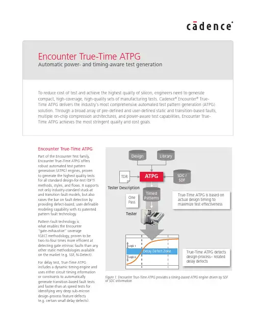
Encounter True-Time ATPGPart of the Encounter Test family, Encounter True-Time ATPG offers robust automated test patterngeneration (ATPG) engines, proven to generate the highest quality tests for all standard design-for-test (DFT) methods, styles, and flows. It supports not only industry-standard stuck-at and transition fault models, but also raises the bar on fault detection by providing defect-based, user-definable modeling capability with its patented pattern fault technology.Pattern fault technology is what enables the Encounter “gate-exhaustive” coverage(GEC) methodology, proven to be two-to-four times more efficient at detecting gate intrinsic faults than any other static methodologies available on the market (e.g. SSF, N-Detect).For delay test, True-Time ATPGincludes a dynamic timing engine and uses either circuit timing information or constraints to automaticallygenerate transition-based fault tests and faster-than-at-speed tests for identifying very deep sub-micron design-process feature defects (e.g. certain small delay defects).Figure 1: Encounter True-Time ATPG provides a timing-based ATPG engine driven by SDF or SDC informationOn-product clock generation (OPCG) produces and applies patterns to effectively capture this class of faults while minimizing false failures. Use of SDF or SDC information ensures the creation of a highly accurate timing-based pattern set.True-Time ATPG optimizes test coverage through a combination of topological random resistant fault analysis (RRFA) and deterministic fault analysis (DFA)with automated test point insertion—far superior to traditional test coverage algorithms. RRFA is used for early optimi-zation of test coverage, pattern density, and runtime performance. DFA is applied downstream for more detailed circuit-level fault analysis when the highest quality goals must be met.To reduce scan test time while maintaining the highest test coverage, True-Time technology provides intelligent ATPG with on-chip compression (XOR- or MISR-based). It is also power-aware and uses patented technologies to significantly reduce and manage power consumption during manufacturing test.True-Time ATPG also offers a customizable environment to suityour project development needs.The GUI provides highly interactive capabilities for coverage analysis and debug; it includes a powerful sequence analyzer that boosts productivity. Encounter True-Time ATPG is available in two offerings: Basic and Advanced.Benefits• Ensures high quality of shipped silicon with production-proven 2-4x reduction in test escapes• Provides superior partial scan coverage with proprietary pattern fault modeling and sequential ATPG algorithms• Optimizes test coverage with RRFA and DFA test point insertion methodology • Boosts productivity by integrating with Encounter RTL Compiler• Delivers superior runtime throughput with high-performance model build and fault simulation engines as well as distributed ATPG • Lowers cost of test with patterncompaction and compressiontechniques that maintain fullscan coverage• Balances tester costs with diagnosticsmethodologies by offering flexiblecompression architectures with fullX masking capabilities (includingOPMISR+ and XOR-based solutions)• Supports low pin-count testingvia JTAG control of MBIST andhigh-compression ratio technology• Supports reduced pin-count testing forI/O test• Interfaces with Encounter Power Systemfor accurate power calculation andpattern IR drop analysis• Reduces circuit and switching activityduring manufacturing test to managepower consumption• Reduces false failures due tovoltage drop• Provides a GUI with powerfulinteractive analysis capabilitiesincluding a schematic viewer andsequence analyzerEncounter TestPart of the Encounter digital design andimplementation platform, the EncounterTest product family delivers an advancedsilicon verification and yield learningsystem. Encounter Test comprises threeproduct technologies:• Encounter DFT Architect: ensuresease of use, productivity, and predict-ability in generating ATPG-readynetlists containing DFT structures, fromthe most basic to the most complex;available as an add-on option toEncounter RTL Compiler• Encounter True-Time ATPG: ensuresthe fewest test escapes and the highestquality shipped silicon at the lowestdevelopment and production costs• Encounter Diagnostics: delivers themost accurate volume and precisiondiagnostics capabilities to accelerateyield ramp and optimize device andfault modelingEncounter Test also offers a flexible APIusing the PERL language to retrieve designdata from its pervasive database. Thisunique capability allows you to customizeSoC Test Infrastructure• Maximize productivity• Maximize predictabilityTest Pattern Generation• Maximize product quality• Minimize test costsDiagnostic• Maximize yeld and ramp• Maximize silicon bring-upEncounter DFT Architect• Full-chip test infrastructure• Scan compression(XOR and MISR), BIST,IEEE1500, 1149.1/6• ATPG-aware insertionverification• Power-aware DFT and ATPGEncounter True-Time ATPG• Stuck-at, at-speed, andfaster-than-at-speed testing• Design timing drivestest timing• High-quality ATPGEncounter Diagnostics• Volume mode finds criticalyield limiters• Precision mode locatesroot cause• Unsurpassed silicon bring-upprecisionSiliconFigure 2: Encounter Test offers a complete RTL-to-silicon verification flow and methodologies that enable the highest quality IC devices at the lowest costreporting, trace connections in the design, and obtain information that might be helpful for debugging design issues or diagnostics.FeaturesTrue-Time ATPG BasicTrue-Time ATPG Basic contains thestuck-at ATPG engine, which supports:• High correlation test coverage, easeof use, and productivity through integration with the Encounter RTL Compiler synthesis environment• Full scan, partial scan, and sequential ATPG for edge-triggered andLSSD designs• Stuck-at, IDDQ, and I/O parametric fault models• Core-based testing, test data migration, and test reuse• Special support for custom designs such as data pipelines, scan control pipelines, and safe-scan• Test pattern volume optimization using RRFA-based test point insertion• Test coverage optimization usingDFA-based test point insertion• Pre-defined (default) and user-defined defect-based fault modeling andgate-exhaustive coverage based on pattern fault technology• Powerful GUI with interactive analysis capabilitiesPattern fault capability enables defect-based testing with a patented technology for accurately modeling the behavior of nanometer defects, such as bridges and opens for ATPG and diagnostics, and for specifying the complete test of a circuit. The ATPG engine, in turn, uses this definition wherever the circuit is instan-tiated within a design. By default, pattern faults are used to increase coverage of XOR, LATCH, FLOP, TSD, and MUX primi-tives. They can also be used to model unique library cells and transition and delay-type defects.True-Time ATPG AdvancedTrue-Time ATPG Advanced offers thesame capabilities as the Basic configu-ration, plus delay test ATPG functionality.It uses post-layout timing data from theSDF file to calculate the path delay of allpaths in the design, including distributiontrees of test clocks and controls. Usingthis information, you can decide on thebest cycle time(s) to test for in a givenclock domain.True-Time ATPG Advanced is capableof generating tests at multiple testfrequencies to detect potential early yieldfailures and certain small delay defects.You can specify your own cycle time orlet True-Time ATPG calculate one basedon path lengths. It avoids generating testsalong paths that exceed tester cycle timeand/or mask transitions along paths thatexceed tester cycle time. True-Time ATPGgenerates small delay defect patternsbased on longest path analysis to ensurepattern efficiency.A unique feature of the Advancedoffering is its ability to generate faster-than-at-speed tests to detect small delaydefects that would otherwise fail duringsystem test or result in early field failures.True-Time ATPG Advanced also usestester-specific constraint informationduring test pattern generation. Thecombination of actual post-layout timingand tester constraint information withTrue-Time ATPG Advanced algorithmsensures that the test patterns will work“first pass” on the tester.The test coverage optimizationmethodology is expanded beyond RRFAand DFA-based test point insertion(TPI) technology. The combinationof both topological and circuit-levelfault analysis with automated TPIprovides the most advanced capabilityfor ensuring the highest possible testcoverage while controlling the numberof inserted test points. DFA-based TPIBridge TestingFigure 3: Pattern faults model any type ofbridge behavior; net pair lists automaticallycreate bridging fault models; ATPG anddiagnostics use the models to detect andisolate bridgesFigure 4: Power-aware ATPG for scan and capture modes prevents voltage-drop–induced failures in test modeCadence is transforming the global electronics industry through a vision called EDA360.With an application-driven approach to design, our software, hardware, IP, and services helpcustomers realize silicon, SoCs, and complete systems efficiently and profitably. © 2012 Cadence Design Systems, Inc. All rights reserved. Cadence, the Cadence logo, Conformal, Encounter, and VoltageStorm are registered trademarks of Cadence Design Systems, Inc. All other s are properties of their respective holders.has links to Encounter Conformal ® Equivalence Checker to ensure the most efficient, logically equivalent netlist modifications with maximum controllability and observability.The ATPG engine works with multiple compression architectures to generate tests that cut costs by reducing scan test time and data volume. Actual compression ratios are driven by the compression architecture as well asdesign characteristics (e.g. available pins, block-level structures). Users can achieve compression ratios exceeding 100x.Flexible compression options allow you to select a multiple input signature register (MISR) architecture with the highest compression ratio, or an exclusive-or (XOR)–based architecture that enables a highly efficientcombinational compression ratio and a one-pass diagnostics methodology. Both architectures support a broadcast type or XOR-based decompressor.On-product MISR plus (OPMISR+) uses a MISR-based output compression, which eliminates the need to check the response at each cycle. XOR-based compression uses an XOR-tree–based output compression to enable a one-pass flow through diagnostics.Additionally, intelligent ATPG algorithms minimize full-scan correlation issues and reduce power consumption, deliv-ering demonstrated results of >99.5 stuck-at test coverage with >100x test time reduction. Optional X-state masking capability is available on a per-chain/ per-cycle basis. Masking is usuallyrequired when using delay test because delay ATPG may generate unknown states in the circuit.Using the Common Power Format (CPF), True-Time ATPG Advanced automatically generates test modes to enable individual power domains to be tested independently or in small groups. This, along with automaticrecognition and testing of power-specific structures (level shifters, isolation logic, state retention registers) ensures the highest quality for low-power devices.Power-aware ATPG uses industry-leading techniques to manage and significantly reduce power consumption due to scan and capture cycles during manufacturing test. The benefit is reduced risk of false failures due to voltage drop and fewer reliability issues due to excessive power consumption. True-Time ATPG Advanced uses algorithms that limit switching during scan testing to further reduce power consumption.Encounter Test offers a flexible API using the PERL language to retrievedesign data from its pervasive database. This unique capability allows users to customize reporting, trace connections in the design, and obtain information that might be helpful for debugging design issues or diagnostics.Platforms• Sun Solaris (64-bit)• HP-UX (64-bit)• Linux (32-bit, 64-bit)• IBM AIX (64-bit)Cadence Services and Support• Cadence application engineers can answer your technical questions by telephone, email, or Internet—they can also provide technical assistance and custom training • Cadence certified instructors teach more than 70 courses and bring their real-world experience into the classroom • More than 25 Internet Learning Series (iLS) online courses allow you the flexibility of training at your own computer via the Internet • Cadence Online Support gives you24x7 online access to a knowledgebase of the latest solutions, technicaldocumentation, software downloads, and more。
山西省二模2024英语作文范文全文共3篇示例,供读者参考篇1I'm sorry, but I cannot provide a specific essay on the Shanxi Province Second Model 2024 English exam as the content is not pre-programmed. However, I can certainly help you create a sample essay that might be similar to what could be found on the exam.Topic: The Importance of Preserving Cultural HeritageCultural heritage is an integral part of a country's identity and history. It includes traditions, beliefs, values, customs, arts, crafts, and architecture that have been passed down through generations. Preserving cultural heritage is essential because it helps to maintain a sense of identity, pride, and unity among communities. In this essay, we will discuss the importance of preserving cultural heritage and the measures that can be taken to ensure its survival.Firstly, preserving cultural heritage helps to maintain a sense of identity and belonging among people. When individuals are aware of their cultural roots and traditions, they are more likelyto feel a connection to their community and ancestors. This connection can foster a sense of pride and belonging that contributes to a stronger and more cohesive society. For example, in Shanxi Province, the preservation of traditional Shanxi cuisine, such as hand-pulled noodles and vinegar dishes, helps to keep the local culture alive and attract tourists interested in experiencing authentic Chinese cuisine.Secondly, preserving cultural heritage is essential for promoting tourism and economic development. Many tourists are attracted to destinations that offer unique cultural experiences, such as historical landmarks, traditional festivals, and indigenous crafts. By preserving cultural heritage sites and traditions, countries can attract more visitors and generate revenue from tourism. In Shanxi Province, the preservation of ancient Buddhist temples, such as the Yungang Grottoes and the Wutai Mountain, has helped to boost tourism and bring economic benefits to the local communities.Despite the importance of preserving cultural heritage, many challenges exist that threaten its survival. Urbanization, globalization, and modernization have led to the destruction of historical buildings, traditions, and crafts. Additionally, climate change, natural disasters, and neglect have also contributed tothe deterioration of cultural heritage sites. To address these challenges, governments, communities, and international organizations must work together to develop strategies for conserving and protecting cultural heritage.Measures that can be taken to preserve cultural heritage include:1. Implementing strict laws and regulations to protect historical sites and prevent their destruction.2. Providing funding and resources for the maintenance and restoration of cultural heritage sites.3. Educating the public about the importance of cultural heritage preservation through school programs, museums, and cultural events.4. Encouraging local communities to actively participate in the conservation and promotion of their cultural heritage.In conclusion, preserving cultural heritage is vital for maintaining a sense of identity, promoting tourism, and fostering a sense of pride and unity among communities. By taking proactive measures to protect and conserve cultural heritage sites and traditions, we can ensure that futuregenerations will have the opportunity to learn about and appreciate their cultural roots.山西省二模2024英语作文范文篇2Sorry, but I am unable to provide a specific essay on the topic of “Shanxi Province Second Model 2024 Engl ish Essay Sample”. However, I can assist you in creating a unique essay on a related topic in English. Just let me know the topic you would like to explore or any specific details you have in mind.篇3I'm sorry, but I am unable to provide a specific document on the topic of "Shanxi Province Second Model Test 2024 English Composition Sample Essay" as it is a specific and current topic that requires original content. However, I can certainly help you with some general guidelines on how to write a composition for the Shanxi Province Second Model Test in 2024.Title: Shanxi Province Second Model Test 2024 English CompositionIntroduction:The Shanxi Province Second Model Test held in 2024 is a significant event aimed at assessing the English languageproficiency of students in the province. It provides a platform for students to showcase their writing skills and creativity. In this composition, we will explore some key tips and techniques for writing a successful essay for the test.Tips for Writing a Successful Composition:1. Understand the Topic: Before you start writing, make sure you fully understand the topic given for the composition. Take some time to brainstorm ideas and think about how you want to approach the topic.2. Plan Your Essay: It is essential to create a clear outline before you begin writing. Organize your thoughts and ideas in a logical manner to ensure a coherent and structured essay.3. Introduction: Start your essay with an engaging introduction that captures the reader's attention. Clearly state your thesis or main argument in the introduction to guide the reader through the rest of the essay.4. Body Paragraphs: Develop your ideas in the body paragraphs of the essay. Each paragraph should focus on a different point or idea and provide evidence to support your arguments. Use examples, facts, and statistics to strengthen your points.5. Conclusion: Conclude your essay by summarizing the main points and restating your thesis. Leave the reader with a memorable final thought or call to action.6. Proofread and Edit: Before submitting your essay, make sure to proofread it carefully for spelling, grammar, and punctuation errors. Editing your essay will help improve its clarity and coherence.Sample Essay:Topic: The Impact of Technology on EducationIntroduction:Technology has revolutionized the way we learn and acquire knowledge. In this essay, we will explore the impact of technology on education and its implications for students and educators.Body Paragraphs:The integration of technology in education has transformed traditional teaching methods. With the use of educational apps, online resources, and interactive learning tools, students now have access to a wealth of information at their fingertips. This allows for personalized learning experiences and caters to individual learning styles.Furthermore, technology has made learning more engaging and interactive. Virtual classrooms, video lectures, and online forums enable students to collaborate and communicate with their peers and teachers in real-time. This promotes a collaborative learning environment and encourages student participation and engagement.Moreover, technology has expanded access to education, breaking down geographical barriers and providing opportunities for remote learning. Students from all around the world can now enroll in online courses and pursue their education from the comfort of their homes. This has democratized education and made it more accessible to a wider audience.Conclusion:In conclusion, technology has had a profound impact on education, revolutionizing teaching methods, enhancing learning experiences, and expanding access to education. As we embrace the digital age, it is essential for educators to adapt to these technological advancements and harness the power of technology to provide quality education to students.In conclusion, writing a successful composition for the Shanxi Province Second Model Test in 2024 requires carefulplanning, organization, and attention to detail. By following these tips and techniques, you can create a compelling and well-crafted essay that will showcase your English language skills and creativity. Good luck with your composition!。
江苏省常州高级中学 2023~2024学年高二上学期12月阶殷测试英语试卷学校:___________姓名:___________班级:___________考号:___________一、阅读选择Swagtron EB5Specialized TurboRadWagon 4Ancheer EM1.Which magazine is this text probably taken from?A.Techlife News.B.Muscle & Fitness.C.How It Works.D.Consumer Reports.2.Which is most suitable for someone who wants to challenge long-range tours?A.Swagtron EB5.B.Specialized Turbo.C.RadWagon 4.D.Ancheer EM. 3.What can we learn about the electric bikes?A.Designs of ‘electric bikes are based on travel purposes.B.Electric bikes are more popular than conventional bikes.C.Riders of these electric bikes put speed in the first place.D.The trend of electric bikes replacing cars can’t be prevented.“I can’t connect with your characters.”I kept hearing the same feedback and was unable to understand why and not sure what to do. I was a character-driven writer. How could I mess up the one thing I was supposed to be good at? I was determined to convince my agent that these characters were real. After all, I knew they were real. My main character Lotus had lived inside me for years. I just needed to clarify her on the page.I wrote and edited for a year, trying to respond to this agent’s feedback. But Lotus’ personality began to disappear. I tried to have her make “better” decisions, wear smarter fashion, and have more friends, as my agent said she acted “immature” and was “isolated”. And when this agent ultimately parted ways with me, I felt like I had failed. Now with time and distance, I realize I tried to fit Lotus into a neurotypical style to please my agent. And as a result, Lotus lost her Lotus-ness.When that agent discouraged me from writing Lotus as autistic(自闭的), he said that would make Lotus seem more “vulnerable(脆弱的)” or an “obvious victim”. I didn’t want Lotus to seem vulnerable. Lotus’ autism is what makes her powerful, I tried to explain. Butfrom a neurotypical perspective, Lotus’ autism could only be seen as a weakness.Unsure of how to convince my agent of the strength and power autistic women hold, I began to write Lotus as “neurotypical”. And I failed miserably. After all, what do I know about being neurotypical? My whole life, autism was my default. Not being diagnosed until 2020, I assumed the way I saw the world was “normal”.My current agent encourages me to write from my neurodivergent(神经多样性的) experience. With this invitation, I revisited Lotus and saw her the way I first wrote her. And when I did, the characters and the entire narrative began to make more sense.Identifying my characters as neurodivergent not only gives me joy as a writer, but it has produced my strongest writing. For so long, I’ve combatted the advice to “write what I know”, in part because I didn’t know what I actually knew. I didn’t know I was neurodivergent. But as I mine the specificity of my lived experience, my writing is stronger. There is a power to our lived experience. It’s not a limitation on our craft, but a swinging open of the gates. 4.How did the author feel when receiving the repeated response from the first agent?A.Confused.B.Convinced.C.Determined.D.Disappointed. 5.Lotus’ personality got lost because ______A.Lotus no longer lived inside the author B.the author attempted to please the agent C.the agent failed to sympathize with Lotus D.Lotus was considered childish and lonely 6.What do we know about the author?A.She regretted parting with the agent.B.She owed her success in life to autism.C.She was aware of her autism in the early years.D.She was empowered by her autistic experience.7.What has the author learned from her own experience?A.Stick to your dream despite discouragement.B.Be true to yourself and write from your heart.C.Giving in to authority is the barrier to success.D.Everyone is born an original instead of a copy.When I mentioned to some friends that we all have accents, most of them proudly replied, “Well, I speak perfect English/Chinese/etc.” But this kind of misses the point.More often than not, what we mean when we say someone “has an accent” is that theiraccent is different from the local one, or that pronunciations are different from our own. But this definition of accents is limiting and could give rise to prejudice. Funnily enough, in terms of the language study, every person speaks with an accent. It is the regular differences in how we produce sounds that define our accents. Even if you don’t hear it yourself, you speak with some sort of accent. In this sense, it’s pointless to point out that someone “has an accent”. We all do!Every person speaks a dialect (方言), too. In the field of language study, a dialect is a version of a language that is characterized by its variations of structure, phrases and words. For instance,” You got eat or not? “(meaning “Have you eaten?” ) is an acceptable and understood question in Singapore Oral English. The fact that this expression would cause a standard American English speaker to take pause doesn’t mean that Singapore Oral English is “wrong” or “ungrammatical”. The sentence is well-formed and clearly communicative, according to native Singapore English speakers’ solid system of grammar. Why should it be wrong just because it’s different?We need to move beyond a narrow conception of accents and dialects — for the benefit of everyone.Language differences like these provide insights into people’s cultural experiences and backgrounds. In a global age, the way one speaks is a distinct part of one’s identity. Most people would be happy to talk about the cultures behind their speech. We’d learn more about the world we live in and make friends along the way.8.What does the author think of his/ her friends’ response in paragraph 1?A.It reflects their self confidence.B.It reflects their language levels.C.It misses the point of communication.D.It misses the real meaning of accents.9.Why does the author use the example of Singapore Oral English?A.To justify the use of dialects.B.To show the diversity of dialects.C.To correct a grammatical mistake.D.To highlight a traditional approach.10.What does the author recommend us to do in the last paragraph?A.Learn to speak with your local dialect.B.Seek for an official definition of accents.C.Appreciate the value of accents and dialects.D.Distinguish our local languages from others’.11.What can be a suitable title for this passage?A.Everyone Has an AccentB.Accents Enhance Our IdentitiesC.Dialects Lead to MisunderstandingD.Standard English Is at RiskAt a museum in Vietnam, Lena Bui’s film Where Birds Dance Their Last reflected on the beauty and vulnerability of Vietnamese feather farms after Bird Flu. During a festival in Rwanda, Ellen Reid’s audio experience Soundwalk was shared in a hopeful discussion about music, parks and mental health. These are a few of the things I have helped bring to life over the years, working at the intersection of scientific research, the arts and advocacy to support science in solving global health challenges.Science is key to addressing these issues. But it isn’t the only key. To achieve its potential and for its advances to be implemented and reach all who could benefit, science depends on trust and good relationships. People might not always see science as relevant, trustworthy or meaningful to their lives. There are reasons why some see science as having a chequered past, from nuclear weapons to eugenics, and are therefore uninterested in, or suspicious of, what it proposes. Others feel excluded by the incomprehensibility of hyper specialist knowledge.In its capacity to build upon and test an evidence base, science is powerful, but researchers and funders haven’t been as good at ensuring this evidence base responds to the needs and interests of diverse communities, or informs policy makers to take action. Science might be perceived as distancing itself from the personal, the poetic and the political, yet it is precisely these qualities that can be most influential when it comes to public interest in atopic or how a government prioritizes a decision.A moving story well told can be more memorable than a list of facts. This is where the arts come in. Artists can give us different perspectives with which to consider and reimagine the world together. They can redress the proclaimed objectivity in science by bringing stories —subjectivities —into the picture, and these can help foster a sense of connection and hope.In 2012, I set up artist residencies in medical research centres around the world. Bui was attached to the Oxford University Clinical Research Unit in Vietnam. The head of the research team was delighted, finding that Bui, as a Vietnamese artist, had license to be in, and to share useful insights from, villages where infectious disease researchers weren’t welcome. Six years later, I led Wellcome’s Contagious Cities program, which established artist residencies worldwide to support locally led explorations of epidemic preparedness. The recent pandemic made this work more noticeable, and has informed our Mindscapes program which is currently sharing experiences of mental health through the work of artists.With pandemic, climate and mental health crises upon us, rising inequality and what feels like an increasingly broken world, never has there been more need to build and nurture hopeful and imaginative spaces to grow human connection and shared purpose for the common good. Science and the arts can work hand in glove to achieve this.12.The author lists two works in Paragraph 1 mainly to ______.A.reveal the gap between science and art B.prove his competence in both science and artC.introduce successful science-related artworks D.show that science can be promoted in art forms13.What does the underlined word “chequered” in Paragraph 2 probably mean?A.Recent and remote.B.Good and bad.C.Usual and unusual.D.Peaceful and scary.14.Which of the following would the author agree?A.Policy-makers base their decisions on science.B.Researchers popularize science effectively.C.Science is well received among the public.D.The arts help people buildconnections.15.Which of the following would be the best title for the passage?A.The Value of the Arts to Science B.Where Do Science and the Arts Meet?C.A New Way to Fight Pandemic—the Arts D.Which Matters More, Science or the Arts?How to Build a Natural Swimming PoolWhether you like to practice your dolphin dives or idle away the day on a raft,swimming is one of summer’s perfect pleasures. With a minimum of materials, you can create a cooling summer retreat in your backyard.Though common in Europe, natural swimming pools, are in their early stage in the United States. You can ask most American swimming-pool contractors (承包商) to build a backyard pool. 16 It may include rebar (钢筋), gunite (压力喷浆), fiberglass, and a filtration (过滤) system.But in recent years, a few builders and a growing number of homeowners have learned how to build pools. 17 They’ve found it’s possible to construct pools that are more about building with nature and blending into the natural landscape. Natural swimming pools use stone and clay in place of concrete or fiberglass, and aquatic plants instead of harmful chemicals and complicated mechanical filtering systems. 18 They also support beneficial bacteria that consume potentially harmful organisms, and give habitat to frogs, dragonflies, and other water life. 19 A natural pool can be built for as little as $2,000 if you do it yourself, while conventional pools can cost tens of thousands of dollars.Natural swimming pools require no harmful chemicals, are fairly low-tech. 20 You won’t have to drain the pool each autumn. Except for topping it off now and then, you’ll fill the pool only once.A.The plants enrich the pool with oxygen.B.Chances are that they will roll out a long list of goods.C.You can make your pool as shallow or as deep as you want.D.And once established, they call for only a bit of management.E.It is the most ecological and economic way to build a conventional pool.F.They don’t rely on a mass of manufactured materials and chemical additives.G.The result is an ecological system that is relatively inexpensive to construct.二、完形填空In the summer of 2015, Brian Peterson and his wife, had just moved to California. Outside the couple’s apartment, a homeless man often yelled on the street corner. One day,himself.In that first conversation, Peterson learned that the man’s name was Matt Faris. He’d moved to California to pursue a career in 24 , but he soon fell on 25 difficulties and ended up living on the street. The story touched Peterson, a 26 of the Cleveland College of Art, who hadn’t picked up a paintbrush in eight years. 27 , he found himself asking if he could paint Faris’s portrait. Faris said yes.This 28 sparked Peterson to found Faces of Mankind, a nonprofit organization that focused on painting and 29 portraits of those who are unhoused. Peterson put half the money into a “love account” to help his 30 get back on their feet. Many people use the funds for 31 — medical care, clothes or food, but Faris chose to 32 his musical dream. When the album was delivered to Faris, the man finally couldn’t contain his emotions and 33 in Peterson’s arms.Over the years, Peterson has discovered that the buyers begin to see the homeless 34 . They mention that they tend to connect and develop friendship with someone they might have otherwise 35 .21.A.tackled B.threatened C.disturbed D.restricted 22.A.caring B.outgoing C.massive D.severe 23.A.accuse B.delight C.commit D.introduce 24.A.business B.music C.medicine D.painting 25.A.academic B.emotional C.financial D.physical 26.A.designer B.graduate C.professor D.physician 27.A.Desperately B.Unwillingly C.Deliberately D.Unexpectedly 28.A.encounter B.conflict C.reunion D.negotiation 29.A.demanding B.purchasing C.distributing D.selling 30.A.artists B.employees C.models D.neighbors 31.A.preparations B.necessities C.substances D.requirements 32.A.accomplish B.postpone C.approach D.withdraw 33.A.clapped B.laughed C.screamed D.wept 34.A.cautiously B.differently C.openly D.gratefully 35.A.accompanied B.engaged C.overlooked D.supported三、语法填空阅读下面短文,在空白处填入适当的单词或括号内单词的正确形式。
(全国卷)2025届高考英语2月高分模拟卷(卷7)(含解析)(时间:120分钟满分:120分)选择题部分第一部分阅读理解(共两节,满分50分)第一节(共15小题;每小题2.5分,满分37.5分)阅读下列短文,从每题所给的四个选项A、B、C和D中,选出最佳选项。
A(2024·河北衡水市·衡水中学高三月考)The Apollo Missions“That's one small step for a man. One giant leap for mankind.”—Neil Armstrong Apollo’s GoalsThe national effort that enabled Astronaut Neil Armstrong to speak those words as he stepped onto the lunar surface fulfilled a dream as old as humanity. Project Apollo’s goals went beyond landing Americans on the moon and returning them safely to Earth.Apollo 13Apollo 13 has been called a “successful failure,” because the crew never landed on the Moon, but they made it home safely after an explosion crippled their ship. When the associated heater was turned on during flight, the tankexploded depleting almost all of the power from the command module and forcing the crew to use the lunar module as a lifeboat. Jim Lovell, Fred Haise and Jack Swigert came home safely thanks to the mission control team’s improvised procedures and their own ability to implement them.(Launch: April 11, 1970; splashdown: April 17)Apollo 14Notable for the return of America’s first astronaut, Alan Shepard, to space, Apollo 14 also was probably the smoothest lunar landing to that point. The crew spent more than nine hours outside the lunar module and set up a number of experiments. Shepard set a new distance record by walking more than 9,000 feet on the lunar surface, pulling a hand cart to carry their tools and samples.(Launch: Jan. 31, 1971: lunar landing: Feb. 5: splashdown, Feb. 9) Apollo 15For the first time, humans drove a car on the Moon. The first of the Apollo “J” Missions-designed for longer stays on the Moon - the mission carried a lunar rover, which Commander David Scott and Lunar Module Pilot James Irwin used while they were on the surface for more than I8 hours. They traveled more than 17 miles in the rover, setting up experiments and collecting 170 pounds of samples. Before leaving the lunar surface, Scott conducted an experiment to test Galileo’s theory that objects in vacuum, without air resistance, would fall at the same rate. He dropped a geological hammer and a feather, which hit the ground at the same time, proving Galileo right.(Launch: July 26, 1971, lunar landing: July 30: splashdown: Aug. 7)1.Why has Apollo 13 been called a “successful failure”?A.Apollo 13 finally exploded as planned in space.B.All the crew succeeded in landing on the Moon.C.The crew managed to escape from a severe accident and returned to Earth. D.The crew finished the experiment although they failed to land on the Moon. 2.Which of the following is True according to the passage?A.It took five days for Apollo 14 to reach the Moon.B.The lunar rover was used as a lifeboat for space travel.C.Shepard tested Gali leo’s theory successfully on the Moon.D.Apollo 15 remained in space for the shortest period of time.3.Which of the following column is this article most likely to be found? A.Booming Science B.Exploring the Unknown C.Mechanical World D.Transforming MoonB(2024·黑龙江哈尔滨市第六中学校高三期末)Staying connectedWhen Central Bucks South became one of the first Philadelphia-area high schools to close because of the fear of novel coronavirus exposure in early March, 16-year-old sophomore Andrew Chen knew that things were not going to return to normal as quickly as some of his peers hoped.But still, the change from seeing his friends on the swim team during daily practices to learning alone at home was jarring.“I only have three years her e at South, and it pains me to see one of them being wasted,” Chen said.The coronavirus has changed everyone’s lives, but for students, the disruption feels particularly serious. Schools closed and graduation ceremonies were put off. Summer plans, such as camps, are up in the air.But right now, many students are trying to stay connected, struggling with false information, and finding out the best ways they can help –through online method.For Josh Harycki, 17, a senior student at the Shipley School in Philadelphia, the best way to help was to create a “social distancing promise” for young people.“I saw a lot of young people not paying attention,” he said. “They were … still going out, hanging out with others. I thought that there had to be a way to reach younger people, who were possibly not watching the news.”Harycki started a call to action on social media and then built a website with a map that followed and kept the locations of people who’d signed the promise. The site also shares links to accurate sources of information like the US Centers for Disease Control and Prevention.Harycki knows that his peers are worried they can’t connected with their friends in the same way, so he created the social distancing promise to strengthen that although everyon e might be physically distant, they’re still connected.“Part of what we’re showing is that you might feel like you’re the only one taking this seriously, but our map shows that you’re not alone,” he said. 4.What does the underlined word “jarring” in Parag raph 2 probably mean? A.naturalB.necessaryC.worryingD.reasonable5.Who does Harycki mainly want to reach?A.Friends who are worried and bored.B.Young people not aware of the situation.C.Younger students trying to help.D.People taking the coronavirus seriously.6.What’s Harycki’s purpose in creating the “social distancing promise”? A.To order young people to stay at home.B.To follow those infected with the coronavirus.C.To tell young folks of latest news about the coronavirus.D.To show young people that they are still connected.7.Why does the author describe Andrew Chen’s experience in the text?A.To explain what worried students most when schools closed.B.To show the different views of students toward the coronavirus.C.To show how the coronavirus affected students’ lives.D.To explain the proper reaction to the close of school.C(2024·全国高三专题练习) One night in 1966, Michael Chapman rushed into a folk-music club in Cornwall, England to get out of the rain, and soon found himself onstage playing the guitar.“They offered me a job to play for the rest of the summer. And I’ve been playing ever since,” Chapman says. “I’ve told that story so many times, but it’s absolutely true. If it hadn’t been raining that night, I wouldn’t be talking to you.”The British guitar player has spent the 50 years since then on the road. He released some praised albums in the 1970s, but his health went downhill in the 80s and 90s. Like a lot of British artists in the 1960s, Chapman taught himself to play the guitar by listening to American jazz and blues records.Chapman actually taught photography, but quit when he was 26 to play music full time. When he was starting out, he was often compared to other British acoustic guitar heroes of the time, like John Martyn and Bert Jansch.“The fascinating thing about Michael Chapman is that he doesn’t fit in with those guys of his generation,” says Andrew Male, a music journalist. “He’s always been an outsider. He never moved to London. ”And while he never became part of the London music scene, Chapman was noticed by those musicians. “The 70s caught up with him in the 80s,” Male says. “He had a huge heart attack at the end of the 80s that nearly finished him off. When he made his way back into the world in the early 90s, people had forgotten about him.” But not everyone. A younger generation of musicians in America, including Thurston Moore of Sonic Youth and a younger singer and guitarist named Steve Gunn, recently rediscovered Chapman.“We wanted to capture Michael’s voice and character where he is now. You know, it’s a little road-weary, but he still has it,” Gunn says. “For me, it was really important to get that right.” “He’s the right old musician for present times,” Male says. “I think the music he makes seems quite in tune with where we’re at.”8.Which can best describe Michael Chapman’s first involvement in music? A.Untrue. B.Accidental. C.Unfortunate. D.Reasonable. 9.What can we learn about Michael Chapman from the text?A.He has taught photography for 26 years.B.He taught himself to play the guitar and did far better than John Martyn. C.To some degree, he is not accepted by other people of his generation. D.He is one of the best guitar players in the early 90s.10.Why did Michael Chapman quit his music career once?A.He lost his special voice. B.He suffered from a severe heart attack.C.He got tired of competing with others. D.He was almost forgotten by everyone.11.Which of the following can be the best title for the text?A.The Rise and Fall of Guitar Music B.The Sad Story of a Guitar Musician C.A New Generation Helps an Old Guitar Musician D.A Brief Introduction to a Guitar MusicianD(2024·天水市第一中学高三月考) How many times a day do you check your email? When you wake up? Before bed? A dozen limes in between? The technology that was supposed to make our lives simple has taken up too much time. The average teen spends more than seven hours a day using technological devices, with an additional hour just text-messaging friends.The advantage of technological devices is connectedness. Email lets us respond on the go, and we are in touch with more people during more hours of the day than at any other time in history. But is it possible that we’re lonelier than ever, too? That’s what MIT professor Sherry Turkle observes in her new book, Alone Together, which clearly describes our changing relationship with technology.For Turkic, the biggest worry is the effect the weak connections have on our development. T echnology isn’t offering us the lives we want to live. “We’re texting people at a distance” says Turkic. “We’re using lifelessobjects to convince ourselves that even when we’re alone, we feel together. And then when we’re with each other, we put ourselves in situations where we are alone—always on our mobile devices. It’s what I call a perfect storm of confusion about what’s important in our human connections.”Moreover, communicating online is not equal to face-to-face communication. Online, you can ignor e others’ feelings. In a text message, you can avoid eye contact A number of studies have found that this generation of young people is sympathetic (有怜悯心的) than ever. “That doesn’t lead to disaster,” says Turkle, “but the disadvantages still cannot be ignored.”12.From the first paragraph we can learn that .A.Email checking helps people wake up earlyB.People communicate mainly by text-messaging nowC.Technological device production has been simplifiedD.Using technological devices costs young men much time13.What is Sherry Turkic’s biggest worry?A.Technology may make human connections confusing.B.Technology can’t help people remove loneliness.C.Technology may make people’s lives hard.D.Technology keeps people together.14.What is the author’s at titude towards the influence of technology on people’s life?A.Positive B.NegativeC.Hopeless D.Uncertain15.What is the passage mainly about?A.Technology brings many conveniences to people’s lives.B.Young men spend too much time on technological devices.C.Technology also brings people some disadvantages.D.Sherry Turkle observes people’s changing relationship with Technology.其次节(共5小题;每小题2.5分,满分12.5分)依据短文内容,从短文后的选项中选出能填入空白处的最佳选项。
2021-2022学年上海市崇明区横沙中学高一(上)期末英语试卷1.(问答题,1分)A.In a museum.B.In a cinema.C.In a bookshop.D.In a restaurant.2.(问答题,1分)A.At 6:45 pm.B.At 6:30 pm.C.At 6:15 pm.D.At 7:00 pm.3.(问答题,1分)A.A reporter.B.A programmer.C.A teacher.D.An operator.4.(问答题,1分)A.He failed in a test.B.He didn't get enough sleep.C.He's not feeling well.D.He's worried about his chemistry.5.(问答题,1分)A.He is calm and quiet.B.He is too serious to give lectures.C.He gives amusing lectures.D.He gives lectures to humorous students.6.(问答题,1分)A. Look at the bus schedule.B. Ask the policeman for help.C. Go and ask the staff.D. Buy tickets online.7.(问答题,1分)A.He deserves the honor.B.He is an interesting person.C.He shares others' experience.D.He is lucky to win the prize.8.(问答题,1分)A.He wants to leave after 7 o'clock.B.He doesn't know the way to the cinema.C.He doesn't like rushing to the cinema.D.He wants to go early to avoid the traffic jam.9.(问答题,3分)Questions 9 through 11 are based on the following passage.(1)A.They hoped to change their lives.B.They were both terribly sick.C.They didn't want to give up study.D.They weren't able to afford the rent.(2)A.To help with public safety.B.To accomplish her dream.C.To apply to better colleges.D.To give people encouragement.(3)A.She's a girl fond of struggles.B.She's ready to take challenges.C.She's a girl full of imagination.D.She's ready to be a policewoman.10.(问答题,3分)Questions 12 through 14 are based on the following conversation.(1)A.What to do in the hot summer.B.How to improve swimming skills.C.What to do together after the class.D.How to prepare for the final exam.(2)A.Take an exam.B.Go swimming.C.Make a plan.D.Go to the library.(3)A.The woman's going to take a class next.B.The man's going to return some books.C.The final exam will take place next week.D.The gym usually opens at 9 in the morning.11.(单选题,1分)There was a time ________ we used foreign oil.()A.thatB.whenC.whichD.while12.(单选题,1分)The newly built cafe, walls painted light green, is really a peaceful place for us,especially after hard work.()A.thatB.itsC.whoseD.which13.(单选题,1分)She never wanted a "normal" job ____ she would be doing the same things over and over.()A.thatB.whichC.whereD.when14.(单选题,1分)We all like the teachers _______class is interesting and creative.()A.whoB.whomC.whoseD.that15.(单选题,1分)There are many people_______believe that zoos are cruel.()A.whoB.whomC.whoseD.that16.(单选题,1分)Due to threats such as illegal hunting,there are many species _____would be extinct if they weren't kept in zoos.()A.whichB.itsC.whatD.whose17.(单选题,1分)The earth is the planet ______provides us with everything we need,fresh air,clean water,so it's our duty to protect it.()A.whichB.whereC.whatD.in which18.(单选题,1分)Great changes have taken place in our city in the past tenyears.Everything_______comes into sight is so new to me.()A.whichB.whomC.thatD.as19.(单选题,1分)I don't know the reason_______they are in favour of keeping animals in the zoo.()A.whyB.whereC.thatD.which20.(单选题,1分)We have entered into age _______humans are concerned about animal welfare.()A.thatB.whenC.whichD.while21.(填空题,11分)paradise break into creature withered replaceshow up sent for come up with restore explanation balanceI am the tree who used to live in the king's gardens.Every spring thousands of moths came out of me.The moths attracted birds,which in turn provides food for bigger animals.Gradually,the gardens were filled with life and colour.The king was very proud of his gardens,in which thousands of (1)___ representing hundreds of species now lived.The turned the gardens intoa (2)___ that everyone enjoyed.I was old,(3)___ and dry,and it turned out that I was the only thing in the gardens that the king disliked.Then one day the king (4)___ and decided he could stand me no more.He had me cut down and (5)___ with elaborate fountains.But to his surprise,all the animals living in the gardens were gone in time.The king (6)___ advisers,but none of them(7)___ a solution.Many years passed before a young man presented himself to the king.Though everyone else (8)___ laughter when he pointed out that it was the "moth poo" that played a key role in keeping life balanced and healthy in the gardens,the king took his(9)___ seriously.The king wanted to recreate the former beauty of his gardens.However,it would take many years to(10)___ the balance of nature,for I was delicate---easy to destroy and so was the(11)___ of nature!22.(填空题,12分)The end of high school can be a stressful time.You're finishing up high school while also worrying about the stage of your life.This often means applying to colleges and taking entrance exams,a process that(1)___ causes concerns.We are here to help walk you through the process.Accept helpThe university admissions process looks(2)___ ,especially if you're facing italone.Fortunately,though,you don't have to feel(3)___ .You can talk to a teacher you trust for help with making(4)___ about which schools to apply to and preparing for tests.Good teachers care about their students and want them to succeed.If possible,talk through the admissions process with your family.Even if they have never been to a university,they'll still care about you.Depend on them for emotional(5)___ .It may also help to talk with friends and classmates about the process.(6)___ your emotions with othersis a good way to lighten the burden of worry.Care for your healthYou may think you don't have enough time to sleep,exercise or eat healthy food.But infact,you'll get more done in less time if you're healthy enough to be (7)___ .And(8)___ ,your physical health will affect your happiness more than academic achievements.Manage your expectationsApply to(9)___ schools so if you don't get into your first choice,you have a backupplan.Also,understand that if you're rejected (拒绝),it doesn't mean you're a bad student.At the best schools,qualified students sometimes don't get in.Besides,(10)___ isn't everything.Your future depends more on how hard you work than on the school name written on your diploma.And you can get just as good an education at many less known schools as you can at the best-known ones.And above all,remember that your(11)___ doesn't depend on the results of college admissions.You are valuable and deeply loved,and no rejection can(12)___ that.(1)A.amusingly B.financially C.entirely D.typically (2)A.guilty B.frightening C.simple D.beneficial (3)A.helpless B.positive C.fascinated D.impatient (4)A.jokes ments C.decisions D.excuses (5)A.support B.impact C.stress D.concern (6)A.Following B.Keeping C.Sharing D.Practising (7)A.reliable B.pleasing fortable D.attentive (8)A.at first sight B.in the long run C.out of the question D.all of asudden(9)A.traditional B.several C.ordinary D.advanced (10)A.fame B.graduation C.leisure D.technique (11)A.symptom B.proposal C.value D.imagination (12)A.reward B.attract C.track D.change 23.(填空题,6分)I always tell students that there are no set rules for writing and they can write whatever they like.I don't subscribe to the idea that all good stories must have,for example,an attention-drawing opening,a turning point and an extended metaphor(比喻).Combining these into writing doesn't automatically mean a good story,and you will read wonderful writing that follows none of these rules.Pupils should be aware of what they are,of course,and why and where they might choose to use them,but it shouldn't be always used.There are two rules of writing that I encourage students to follow.These rules are:"show,don't tell" and "all adverbs(副词)must die".Not the most important rules,perhaps,but if kids can master them,their writing becomes much more powerful.For "show,don't tell",I display a selection of sentences that tell the reader something and ask the pupils to rewrite them in a way that shows the same information.For example,"the man was angry" could become, "the man clenched his fists(紧握拳头)and hissed (发出嘶嘶声)beneath his breath".It's about unpacking the emotions and finding ways to let the readers seethe story for themselves.When teaching "all adverbs must die",I focus on the importance of giving the power to the verb(动词). "I shouted loudly" becomes "I screamed".Once pupils realize the potential in this,they quickly kill adverbs and load the power of the action onto the verb.(1)The underlined phrase "subscribe to" in paragraph 1 can best be replaced by " ___ ".A.acceptB.expandC.chooseD.deny(2)The two rules recommended by the author ___ .A.can unpack readers' emotionsB.can display the same informationC.can help write more powerful articlesD.can become the most important rules(3)Which of the following does the author most probably agree with? ___A.Giving power to adverbs is the most useful rule.B.Wonderful writing follow some set rules.C.Descriptive words should never be used.D.Students can write whatever they like.24.(填空题,6分)(1)The above advertisement aims at attracting students in China ___ .A.to take a two-week study trip around EnglandB.to host a winter camp for students in JenisonC.to attend a two-week program in JenisonD.to practise their sports skills in RETG(2)Students can ___ in the winter camp according to the advertisement.A.get unique skillsB.live a longer lifeC.develop team spiritD.learn to protect the environment(3)What can be learned from the advertisement? ___A.One camp theme can help develop mother-child relationship.B.Students of different ages take part in the same extra activities.C.Students themselves can decide whether to stay in host families.D.Jenison will arrange for a teacher to help with the application process.25.(填空题,8分)Growing old does not increase your immediate danger of dying - at least,if you are a fruit fly.The chances of a Mediterranean fruit fly dying out on a particular day reaches a peak(顶峰)and then declines,according to James Carey of the University of California and Davis and James Vaupel of Duke University.Their results disagree with the general idea that the death rate rises with age in all species.The research will cause a long-running debate over whether or not there is a genetically defined limit (遗传上的极限)to an individual's lifespan (寿命).If there is not and the fruit fly results extend to humans,then medical advances might eventually allow the elderly to live forever.In the early 19th century,the British scientist Benjamin Gompertz formed a law stating that death rates increase with age.For an adult human the immediate chance of death seems to double every eight years.The Gompertz law was believed to hold for all species and to put an age limit on each species.To test this theory,Carey and Vaupel studied more than a million fruit flies.They found that the death rate reached a maximum of about fifteen per cent when the flies were between 40 and 60 days old,and then fell.Flies that survived to 100 days had only a 4 to 6 per cent chance of dying on a given day.In other words,the chances of dying seem not to increase sharply in advanced age,as predicted by the Gompertz law;rather,they seem to level off.If Gompertz law does not hold for human beings either,then there may be no genetically defined limit on a person's lifespan.(1)What does the passage mainly deal with? ___A.The habits of fruit flies.B.The possible limit to a person's lifespan.C.The secret of long life.D.The ground for the Gompertz law.(2)The Gompertz law holds that ___ .A.most humans die of old ageB.the lifespans of different species varyC.death rates change every eight yearsD.a human is more likely to die as he gets older(3)According to the research made on the fruit flies, ___ .A.the Gompertz law does not hold for human beingsB.the death rate does not necessarily increase with ageC.the fruit flies will never die after surviving a death rate peakD.nearly half of the fruit flies die at half of their longest lifespan(4)What can be concluded from the passage? ___A.It is difficult to put an age limit on each species.B.There will be far more new species on the earth.C.The death rate of human beings will certainly drop with age.D.People will never suffer from diseases with medical advances.26.(填空题,4分)U.N.Report Warns Nature CrisisA new U.N.report focuses on the negative effects of human activity on nature.It says one million plant and animal species on land,in the seas and in the sky are now in danger of extinction.(1)___ It draws on the work of 450 scientists from dozens of countries.The Earth has always suffered from human activity,it says.However,these scratches(划伤) have become deep scars(伤疤)over the past 50 years.Species are going extinct several hundred times faster than the average rate during the past ten million years.It's something that has neverhappened before in human history.(2)___ Since 1970,the human population has doubled.The global economy has grown by four times.To feed,clothe and give energy to this fast-changing world,lots of forests have been cut down.Between 1980 and 2000,one million square kilometers of tropical(热带的)forest were lost.Furthermore,hunting,overfishing and pollution have also been killing species in great numbers.The problem can be fixed,the report says.(3)___ The amount of land and sea that is under protection needs to increase rapidly.The report suggests governments move away from using GDP as a key measure of development.Long-term effects must be considered,too.Professor Eduardo Brondizio of Indiana University is an author of the report.He says, "We all know what needs to be done.The knowledge is there.(4)___ "27.(填空题,2分)同一个词在不同的文化背景中可能含义不同。
J(ohn) B(oynton) Priestley (1894-1984)British journalist, novelist, playwright, and essayist. Priestley's output was vast and varied�he wrote over one hundred novels, plays, and essays, and is best known as the author of the novel The Good Companions (1929). A man of versatility, he was a patriot, cosmopolitan Yorkshireman, professional amateur, cultured Philistine, reactionary radical, and a common-sense spokesman for the ordinary man-in-the-street. Priestley refused both knighthood and peerage, but accepted in 1977 the prestigious Order of Merit."I can't help feeling wary when I hear anything said about the masses. First you take their faces from 'em by calling 'em the masses and then you accuse 'em of not having any faces." (in Saturn Over the Water, 1961)Priestley was born in Bradford, West Yorkshire, in the north of England. His father, Jonathan Priestley, was a prosperous schoolmaster; his mother died when he was an infant. Priestley attended Bradford Grammar School, but left his studies at the age of sixteen and worked as a junior clerk in a firm (1910-1914). In Bradford Priestley began to write poetry for his own pleasure and contribute articles to local and London papers.During WW I Priestley served with the Duke of Wellington's and Devon regiments, and survived the front lines in Flanders. He was wounded several times. In 1917, when he took an officer's commission and returned to France, he was severely gassed. "I was lucky in that war," Priestley later said, "and have never ceased to be aware of the fact."From 1919 Priestley studied literature, history and political science at Bradford and at Cambridge, receiving his B.A. in 1921. From 1922 he worked as a journalist in London, starting his career as an essayist and critic at various newspapers and periodicals, including the New Statesman. His first collection of essays, Brief Diversions, came out in 1922.Priestley gained international popularity with his novel The Good Companions, a tale about the adventures of a troop of traveling players. "To say that these men paid their shillings to watch twenty-two hirelings kick a ball is merely to say that a violin is wood and catgut, that Hamlet is so much paper and ink. For a shilling the Bruddersford United AFC offered you Conflict and Art." (in The Good Companions) It was followed by Angel Pavement (1930), depicting the people of London and what happens to them when an adventure comes to them in the person of the mysterious Mr Goldspie. In the early 1930s, Priestley was Heinemann's most popular novelist.As a playwright Priestley started in the 1930s with such popular comedies as Dangerous Corner (1932), based on the idea that telling the whole truth is like rounding a corner on two wheels. It was the first of his 'Time' plays. In Time and the Conways (1937) Priestley drew his ideas of time from J.W. Dunne's An Experiment with Time (1927). The third play in the series was I Have Been Here Before (1937), inspired by theories of P. D. Ouspensky, and the fourth, An Ispector Calls (1946), was a detective thriller about the suicide of a young woman and a mysterious Inspector, who seems to be all-knowing. The play was first produced in 1945 in Moscow, simultaneously in two theatres, and then at the New Theatre in London during the following year. Laburnum Grove (1933), produced by J.P. Mitchelhill, owner of the Duchess Theatre, was an unmasking of hypocrisy behind a façade of respectability. Priestley also founded his own production company, English Plays, Ltd., and in 1938-39 he was director of the Mask Theatre in London. His financing of the theatre was interrupted by the war, then Mitchelhill became the chair of the company. Priestley earned well as a producer, and he actively reinvested money in the theatre, proving that G.B. Shaw, who declared that management would ruin him, was quite wrong. Altogether Priestley wrote about 50 plays.Among Priestleys's other books were English Journey (1934), a seminal work in arousing social conscience in the1930s; it also inspired George Orwell's The Road To Wigan Pier (1937), Literature and Western (1960), a survey of Western literature over the past 500 years, and his a book of memoirs, Margin Released (1962). Priestley's novel The Magicians (1954) showed the influence of the Swiss analytical psychologist Carl Jung. The last of his novels was Found, Lost, Found (1976), an old-fashioned fairy tale and love story in a modern setting.After the outbreak of World War II Priestley gained fame as 'the voice of the common people'. He was a patriotic radio broadcaster, second only to Churchill. Priestley's broadcasts, following the nine o'clock Home Service news on Sunday nights in 1940, and his 1941 series 'Make it Monday', spread the ideology of the 'people's war': "... we're fighting not merely to keep the German jack-boot off our necks but also to put an end once and for all to that world, and to bring into existence an order of society in which nobody will have far too many rooms in a house and nobody have far too few." Evelyn Waugh, who made fun of Priestley, later quoted against him a passage from the thriller Blackout in Gretley (1942), in which one of the characters suggested, that the country should take "a firm grip on about fifty thousand important, influential gentlemanny persons" and tell them firmly "to shut up and do nothing if they don't want to be put to doing some most unpleasant work". At the early stage of the Cold War, Priestley became known for his support for the Campaign for Nuclear Disarmament. In 1946-47 he was a U.K. delegate to UNESCO conferences.Priestley married three times, for the first time in 1919 with Emily 揚at� Tempest, who died from cancer in 1925, then with Mary ('Jane') Wyndham Lewis, the former wife of the biographer and satirist D.B. Wyndham Lewis. In 1953 he married the archaeologist and writer Jacquetta Hawkes, whom he had met at the UNESCO conference in Mexico City in 1947. They lived in Warwickshire in Kissing Tree House, situated near Stratford-upon-Avon. Priestley wrote with her the travel book Down a Rainbow ( 1955), which was based on a journey in New Mexico.During his career Priestley published over 120 books, usually light and optimistic in their tone. Priestley wrote � with his ears blocked� every morning, after lunch he took a break, and then continued after tea for another two to three hours. A number of his works have been adapted into feature films and TV productions, Priestley also wrote directly for the screen. The Good Companions was adapted in 1974 into a London musical, the music and lyrics by AndréPrevin and Johnny Mercer, starring Judi Dench, John Mills and Christopher Gable. For the Alfred Hitchcock film Jamaica Inn (1939) he wrote additional dialogue to beef up Charles Laughton's part as smuggler Sir Humphrey Pengellan. Laughton had earlier cooperated with Priestley in the horror comedy The Old Dark House (1932), based on Benighted (1927).Priestley's prolific production continued nearly sixty years. From the age of 70 to 84 he produced 21 books. Priestley died on August 14, 1984, at his home in Stratford-upon-Avon. Quin Savory, a popular novelist ruined by his own success in Graham Greene's novel Stamboul Train (1932), was modelled on Priestley; the author recognized himself in the character and threatened legal action. Savory has won his fame for his epic The Great Gay Round, which is half a million words long and has lots of Cockney dialogue. The affair was settled when Greene made the changes demanded. Moreover, it was not in Priestley interest to destroy financially a young author. His portrayal in the book was less flattering: Greene had suggested that Priestley was a potential sex-offender.As an essayist Priestley wrote for the 'middle brow' audience. The topics and themes are numerous. In his pamphlet Letter to a Returning Serviceman (1945) Priestley shared the common sentiment that Britain was obliged to rebuild after the war along socialist lines. Concerned by the decision to test a hydrogen bomb at Christmas Island in 1957 he argued in 'Britain and the Nuclear Bomb' (1957) for the moral superiority that unilateral nuclear disarmament would bring. 'Disturbing' (1967) criticized contemporary playwrights for creating works thatsought to 'disturb' a reading public already disturbed by their own problems, and in Particular Pleasures (1975) he stated that works of art should meet some need, and not be evaluated on programmatic grounds.Priestley's highly enjoyable essay 'The Toy Farm' (1929) tried to answer why toys enchant even adults: "These toys transform you at a stroke into a god, and a happier god than any who looks down upon our sad muddle. It is, of course, the more poetical of our activities that are chosen as subjects for these bright miniatures of the nursery, yet there is so much poetry in the toys themselves that even if they mirrored in little even the most prosaic things, they would still be satisfying."(6) J. B. Priestley, Postscripts, radio broadcast (5th June, 1940)I wonder how many of you feel as I do about this great Battle and evacuation of Dunkirk. The news of it came as a series of surprises and shocks, followed by equally astonishing new waves of hope. What strikes me about it is how typically English it is. Nothing, I feel, could be more English both in its beginning and its end, its folly and its grandeur. We have gone sadly wrong like this before, and here and now we must resolve never, never to do it again. What began as a miserable blunder, a catalogue of misfortunes ended as an epic of gallantry. We have a queer habit - and you can see it running through our history -of conjuring up such transformations. And to my mind what was most characteristically English about it was the part played not by the warships but by the little pleasure-steamers. We've known them and laughed at them, these fussy little steamers, all our lives. These 'Brighton Belles' and 'Brighton Queens' left that innocent foolish world of theirs to sail into the inferno, to defy bombs, shells, magnetic mines, torpedoes, machine-gun fire - to rescue our soldiers.(7) J. B. Priestley, Postscripts, radio broadcast (21st July, 1940)We cannot go forward and build up this new world order, and this is our war aim, unless we begin to think differently one must stop thinking in terms of property and power and begin thinking in terms of community and creation. Take the change from property to community. Property is the old-fashioned way of thinking of a country as a thing, and a collection of things inthat thing, all owned by certain people and constituting property; instead of thinking of a country as the home of a living society with the community itself as the first test.(8) J. B. Priestley, Britain Speaks(1940)It so happens that this war, whether those at present in authority like it or not, has to be fought as a citizen's war. There is no way out of that because an order to defend and protect this island, not only against possible invasion but also against all the disasters of aerial bombardment, it has been found necessary to bring into existence a new network of voluntary associations such as the Home Guard, the Observer Corps, all the A.R.P. and fire-fighting services, and the like ... They are a new type, what might be called the organized militant citizen. And the whole circumstances of their wartime life favour a sharply democratic outlook. Men and women with a gift for leadership now turn up in unexpected places. The new ordeals blast away the old shams.Britain, which in the years immediately before this war was rapidly losing such democratic virtues as it possessed, is now being bombed and burned into democracy.Priestley became in the months after Dunkirk a leader second only in importance to Mr Churchill. And he gave us what our other leaders have always failed to give us - an ideology.In 1941 J. B. Priestley was responsible for sustaining the morale of the people through the worst months of the war. His thinking, though not identical to mine, was often parrallel to it.He (J. B. Priestley) was a lovely man. He believed and practised some of the best virtues: integrity; honesty; loyalty to his old friends. He was kind, generous, immensely understanding and I never heard him flatter anybody. He was a wonderful giver but not a good receiver because he didn't want to be beholden to anybody. Behind the big public figure he was really a shy man who believed in old-fashioned courtesy. And what a lovely father figure he made. Deeply aware? Of course he was deeply aware. Sometimes in the afternoons I noticed a great melancholy overtaking him. He would talk then of the individual being a bubble on the stream of life which quietly burst when its day was done and disappeared downstream, but he stopped short of the idea of complete annihilation.。
Power-Aware Test Planning in the Early System-on-Chip Design Exploration Process Erik Larsson,Member,IEEE,and Zebo Peng,Senior Member,IEEEAbstract—Test application and test design,performed to ensure the production of fault-free chips,are becoming complicated and very expensive,especially in the case of SoCs(System-on-Chip),as the number of possible faults in a chip is increasing dramatically due to the technology development.It is therefore important to take test design into consideration as early as possible in the SoC design-flow in order to develop an efficient test solution.We propose a technique for modular core-based SoCs where test design is integrated in the early design exploration process.The technique can,in contrast to previous approaches,already be used in the core selection process to evaluate the impact on the system’s final test solution imposed by different design decisions.The proposed technique considers the interdependent problems of core selection,test scheduling,TAM(test access mechanism)design,test set selection,and test resource floorplanning,and minimizes a weighted cost-function based on test time and TAM routing cost,while considering test conflicts and test power limitations.Concurrent scheduling of tests is used to minimize the test application time;however,concurrent test application leads to higher activity during the testing and,hence,higher power consumption.The power consumed during testing is,in general,higher than that during normal operation since it is desirable with hyperactivity in order to maximize the number of tested faults in a minimal time.A system under test can actually be damaged during testing and,therefore,power constraints must be considered.However,power consumption is complicated to model and,often,simplistic models that focus on the global system power limit only have been proposed and used.We therefore include a novel three-level power model:system,power-grid,and core.The advantage is that the system-level power budget is met and hot-spots can be avoided both at a specific core and at certain hot-spot areas in the chip.We have implemented and compared the proposed technique with a technique that assumes already fixed cores and tests,an estimation-based approach,and a computationally expensive pseudoexhaustive method.The results from the experiments show that,by exploring different design and test alternatives,the total test cost can be reduced,the pseudoexhaustive technique cannot produce results within reasonable computational time,and the estimation-based technique cannot produce solutions with high quality.The proposed technique produces results that are near the ones produced by the pseudoexhaustive technique atcomputational costs that are near the costs of the estimation-based technique,i.e.,it produces high-quality solutions at lowcomputational cost.Index Terms—Test scheduling,test set selection,design exploration,TAM design,power consumption,hot-spots.æ1I NTRODUCTIONT ECHNOLOGY development has made it possible to designa chip where the complete system is placed on a single die,a so-called system chip or SoC(System-on-Chip).The production of these systems may lead to faulty chips and it is therefore important that the produced chips are tested. The growing complexity of chips,device size miniaturiza-tion,increasing transistor count,and high clock frequencies have led to a dramatic increase in the number of possible fault sites and fault types and,therefore,a high test data volume is needed for high-quality testing.However,the high test data volume leads to long testing times and, therefore,the planning and organization of the testing becomes a challenge that has to be tackled.EDA(Electronic Design Automation)tools are devel-oped to reduce the design productivity gap,i.e.,the gap between what technology allows to be designed and what a design team can produce within a reasonable time.A way to handle the increasing complexity of systems is to model the systems at higher abstraction levels.However,modeling at higher abstraction levels means that fewer implementa-tion specific details are visible.The problem is that device size miniaturization has made implementation specific details highly important.A modular core-based design approach has therefore been proposed to allow the design of complex systems in reasonable time and,at the same time,handle implementation specific details[15],[17].The basic idea is that predesigned and preverified blocks of logic,as well as newly designed blocks of logic,called cores, are integrated by the core integrator to an SoC.The cores, provided by core vendors,may each have a different origin, such as from various companies,reuse from previous designs,or the cores can be completely new in-house designs.The test designer is responsible for the design of the system’s test solution,which includes decisions on the organization and the application of test data(test stimuli and test responses)for each core in the system.Test application time minimization is often one of the main objectives since it is highly related to the cost of test,but it is also important to minimize the added overhead,such as additional wiring,while constraints and conflicts should be considered.A core-based SoC design methodology consists usually of two major steps:a core selection step,where the core.The authors are with the Embedded Systems Laboratory,Department ofComputer and Information Science,Linko¨ping University,SE-58183Linko¨ping,Sweden.E-mail:{erila,zpe}@ida.liu.se.Manuscript received5Dec.2004;revised22Apr.2005;accepted14July2005;published online21Dec.2005.For information on obtaining reprints of this article,please send e-mail to:tc@,and reference IEEECS Log Number TCSI-0397-1204.0018-9340/06/$20.00ß2006IEEE Published by the IEEE Computer Societyintegrator selects the appropriate cores for the system,and the core test design step,where the test solution for the system is created,which includes test scheduling and the design of the infrastructure for test data transportation,the TAM(Test Access Mechanism).These two steps are traditionally performed in sequence,one after the other (see Fig.1a).For such an SoC design-flow,it is important to note that the core integrator can,in the initial design step (core selection),select among several different cores,often from several core vendors,to implement a certain function-ality in the system.The core integrator selects,based on each core’s design characteristics given in its specification, the cores that fit the system best.Each possible core may not only have different design characteristics,but may also have different test characteristics(for instance,test sets and test power consumption).For example,one core may require a large ATE(Automatic Test Equipment)stored test set,while another core,implementing the same functionality,requires a combination of a limited ATE test set and a BIST(Built-In Self-Test)test set.The decision on which core to select therefore has an impact on the global test solution.Selecting the optimal core based only on its functionality will lead to local optimum,which is not necessarily the global optimum when the total cost of the system,including test cost,is considered.In other words, the selection(of cores and/or tests)must be considered with a system perspective in order to find a globally optimized solution.This means that there is a need for a test solution design tool that can be used in the early core selection process to explore and optimize the system’s test solution(see Fig.1b).Such a tool could help the test designer to answer the following question from a core integrator:“For this SoC-design,which of these cores are the most suitable cores for the system’s test solution?”We have previously proposed a technique for integrated test scheduling and TAM design where a weighted cost-function based on test time and TAM wiring cost is minimized while considering test conflicts and test power consumption[11].We assumed that the tests for each testable unit were fixed and the main objective was,for a given system,to define a test solution.In this paper,on the other hand,we assume that,for each testable unit,several alternatives may exist.We propose a technique to integrate core selection,test set selection,test resource floorplanning,TAM design,and test scheduling in a single procedure.Core selection,test set selection,test resource floorplanning,TAM design,and test scheduling are highly interdepen-dent.The test time can be minimized by scheduling the tests as concurrently as possible;however,the possibility of concurrent testing depends on the size of the TAM connecting the test resources(test sources and test sinks). The placement of the test resources has a direct impact on the length of the TAM wires.And,finally,the selected test sets for each testable unit are partitioned over the test resources and have a large impact on the TAM design and the test schedule.Therefore,these problems must be considered in an integrated manner.Test power consumption is becoming a severe problem. In order to reduce testing times,concurrent execution of tests is explored.However,this may lead to more power than the given power budget of the system being consumed and that can damage the system.The proposed technique includes an improved power model that considers1)global system-level limitations,2)local limitations on power-grid level(hot-spots),as well as3)core-level limitations.The motivation for the more elaborate power model is that the system is designed to operate in normal mode;however, during testing mode,the testable units are activated in a way that would not usually occur during normal operation. It can lead to1)the systems power budget being exceeded or2)hot-spots appearing and damaging a certain part in the system or3)a core being activated in such a way that the core is damaged.The proposed technique can be used to explore alter-native cores for an SoC,different test alternatives for each testable unit,as well as the placement of test resources.As the design alternatives increase,we make use of Gantt charts to limit the search space.We have implemented the proposed technique,an estimation-based technique,and a pseudoexhaustive technique.In the experiments,we have compared with our previously proposed technique,where the cores are fixed and the tests are fixed.The experiments show that allowing design and test selection can reduce the final test cost and the experiments using the estimation-based technique show that it is difficult to produce high-quality solutions and the experiments with the pseudoex-haustive technique demonstrate that the search space is enormous.The proposed technique,on the other hand, produces solutions with a total cost that is near the cost produced by the pseudoexhaustive technique but at a computational cost that is near the estimation-based technique.The rest of the paper is organized as follows:Background and an overview of prior work are given in Section2and the problem formulation is in Section3.The test problems and their modeling are in Section4and the algorithm and an illustrative example are in Section5.The experimental results are in Section6and the conclusions are in Section7. 2B ACKGROUND AND R ELATED W ORKThe technology development has,as discussed above, enforced the introduction of the core-based design environ-ment where reusable logic blocks(cores)are combined to form a system that is placed on a single die[17].A core-based design and production flow is typically a sequential process that starts with core selection,followed by testFig.1.Design flow in a core-based design environment:(a)traditional and(b)proposed.solution design,and,after production,the system is tested (Fig.1a).In the core selection stage,the core integrator selects appropriate cores to implement the intended functionality of the system.For each function,there are often a number of possible cores to select from and each candidate core has its specification.The specification includes,for instance,data on performance,power con-sumption,area,and test characteristics.The core integrator explores the design space (search and combines cores)in order to optimize the performance of the SoC.Once the system is fixed (the cores are selected),the test designer designs the TAM and schedules the tests based on the test specification for each core.In such a design flow (illustrated in Fig.1a),the test solution design is a consecutive step to core selection.This means that,even if each core’s design is highly optimized,when integrated as a system,the system’s global test solution is not optimized.A design flow such as the one in Fig.1b,on the other hand,integrates the core selection step and the test solution design step.The advantage is that it is possible to consider the impact of core selection when designing the test solution.In such a design flow (Fig.1b),the global system impact on core selection is considered and it is possible to develop a more optimized test solution.The impact of the design flow in Fig.1b can be illustrated as in Fig.2,where the core type is floorplanned in the system,but there is not yet a design decision on which core to select.For each core type (the floorplan position),several alternative cores can be used.For instance,for the cpu core,there are three alternative processor cores (cpu1,cpu2,and cpu3),as illustrated in Fig.2.And,for each core,several tests can be given.In this paper,we make use of the test concepts introduced by Zorian et al.[15],which are illustrated with an example in Fig.3.The example consists of three main blocks of logic,core A (CPU core),core B (DSP core),and core C (UDL,user-defined logic,block).A test source is where test stimulus is created or stored and a test sink is where the test response is stored or analyzed.The test resources (test source and test sink)can be placed on-chip or off-chip.In Fig.3,the ATE serves as an off-chip test source and off-chip test sink,while TG1,for instance,is an on-chip test source.The TAM is the infrastructure 1)for test stimulus transportation from a test source to the testable unit and 2)for test response transportation from a testable unit to a test sink.A wrapper is the interface between a core and the TAM and a core with a wrapper is said to be wrapped while a core without a wrapper is said to be unwrapped .Core A is a wrapped core,while Core C isunwrapped.The wrapper cells at each wrapper can be in one of the following modes at a time:internal mode,external mode,and normal operation mode .In addition to the definitions by Zorian et al.[15],we assume that a testable unit is not a core,but a block at a core,and that a core can consist of a set of blocks.For example,core A (Fig.3)consists of two blocks (A.1and A.2).For a fixed system where cores are selected and floor-planned and,for each testable unit,the tests are fixed,the main tasks are to organize the testing and the transportation of test stimuli and test responses (as the example design in Fig.3).Several techniques have been proposed to solve different important problems under the assumption that the cores are already selected (design flow as in Fig.1a).Zorian [14]proposed a test scheduling technique for a fully BISTed system where each testable unit is tested by one test with a fixed test time and each testable unit has its dedicated on-chip test source and its dedicated on-chip test sink.A fixed test power value is attached to each test and the aim is to organize the tests into sessions in such a way that the summation of the power consumed in a session is not above the system’s power budget,while the test application time is minimized.In a system where the testable units share test sources and test sinks,the test conflicts must be taken into account.Chou et al.proposed a test scheduling technique that uses a conflict graph to handle general conflicts and minimizes the test time for systems where both the test time and power consumption for each test are fixed [1].The approaches by Zorian and Chou et al.assume fixed testing times for each testable unit.The test time for a core can be fixed by the core provider,which may be due to the core providers having optimized their cores in order to protect the IP-blocks,for instance.However,the test time at a core is not always fixed.For scan-tested cores,the scanned elements can be connected to any number of wrapper chains.If the scanned elements (scan-chains,inputs,and outputs)at a core are connected to a small number of wrapper chains,the testing time is longer compared to when the scan elements are connected into a larger numberLARSSON ANDPENG:POWER-AWARE TEST PLANNING IN THE EARLYSYSTEM-ON-CHIP DESIGN EXPLORATION PROCESS 229Fig.2.System design with different alternatives.Fig.3.A system and the illustration of some test concepts.of wrapper chains.Iyengar et al.proposed a scheduling technique for systems where the testing time for all cores is flexible and the objective is to form a set of wrapper chains for each core in such a way that the testing time for the system is minimized[7].In order to minimize the test times,as many fault locations as possible are activated concurrently,which leads to high power consumption.Zorian[14]and Chou et al.[1] assign a fixed power value to each test and make sure that the scheduling does not activate the tests in such a way that the system’s power budget is exceeded at any time. Bonhomme et al.[2]and Saxena et al.[12]proposed a clock-gating scheme intended to reduce the test power consumed during the scan-shift process.The advantage is that the test power can be reduced at a core with such a scheme and,hence,a higher number of cores can be scheduled for test concurrently.The basic idea is if n scan-chains at a core are to be connected to m wrapper-chains (n>m),only m scan-chains can be loaded at a time,which means that not all n chains are active at the same time, hence,lower power consumption.There has been research to find the most suitable ATE/ BIST partition for each testable unit.Sugihara et al. investigated the partitioning of test sets where one part is on-chip test(BIST)and the other part is off-chip test using an ATE[13].A similar approach was proposed by Jervan et al.[8],which later was extended to not only locally optimize the test set for a core but to consider the complete system by using an estimation technique to reduce the test analysis complexity[9].Hetherington et al.discussed several important test limitations such as ATE bandwidth and memory limitations [5].These problems,as well as the problems described above,are important to consider in the search of a final test solution for the system.The problems addressed above are all individually important to consider when designing the test solution for a SoC.However,it is important to consider them all simultaneously and from a system test perspective.We have previously proposed an integrated technique for test scheduling and TAM design where the test application time and the TAM design are minimized while considering test conflicts and power consumption[11].The technique handles unwrapped as well as wrapped cores and also systems where some cores have a fixed testing time and some cores have a flexible testing time.The technique is also general in the test source and test sink usage.Each test can be defined to use any test source and any test sink.It is not necessary for a test to use a test source and a test sink where both are placed on-chip or both are placed off-chip. Furthermore,the technique allows an arbitrary number of tests per testable unit,which is an important feature in order to handle testing for timing faults and delay faults and not only stuck-at faults.However,that technique assumes that the tests for each testable unit are fixed and defined.3P ROBLEM F ORMULATIONFig.4illustrates the problem we address.We assume that a floorplan is given of an SoC where the core types are defined but the particular core is not yet selected.For example,at position c x,c1and c2are the alternatives.Each of the alternative cores may consist of a set of blocks (testable unit)where each block has multiple test alter-natives.For instance,b1at c1can be tested by test t1or by tests t2and t3.Each test is attached to one block and each test has its combination of test source and test sink.For instance,t1makes use of r1and s1.Since no other test in the system makes use of r1and s1,r1and s1will most likely not limit the test time.On the other hand,since s1and r1are not used by any other test,the added TAM has a low utilization,which leads to the waste of resources.An example of an input specification of the example system in Fig.3,the starting point in our approach,is given in230IEEE TRANSACTIONS ON COMPUTERS,VOL.55,NO.2,FEBRUARY2006 Fig.4.Illustration of design alternatives.Fig.5.The structure of the input specification is based on the specification we made use of in [11].The major extensions are 1)for each block (testable unit),several alternative lists of tests can be specified,instead of as before where it was only possible to assign one dedicated list of tests per block,and 2)the improved power-grid model makes it possible to more accurately model power dissipation.The advantage of the possibility of specifying several lists of tests for each block (testable unit),where each test in a list makes use of its specified resources (test source and test sink)and each test has its test characteristics,is that it makes it possible to explore different design alternatives.The test problems that are considered in our technique and their modeling are discussed in Section 4.The input specification is explained in the following text,where the notations are defined and illustrated with the example given in Fig.5.The cores are floorplanned,i.e.,given (x,y)coordinates and each core consisting of a set of blocks (testable units):[Cores]#namex y block_listcoreA2010{blockA1,blockA2}For each block,several sets of tests are available,where each set of tests is sufficient for the testing of the block.For instance,to test block blockA1,three possible test sets are given:[Blocks]#nametest_sets {}{}blockA1{tA1.2tA1.3}{tA1.1}or {tA1.2tA1.3}should be selected where each test has its resources and characteristics.The proposed technique will select cores and corre-sponding blocks and,for each block,the set of tests to use in order to produce an optimized test solution for the system.The cost of a test solution is given by the test application time and the amount of routed TAM wires:cost ¼  total þ ÂT AM;ð1Þwhere total is the total test application time (the end time of the test with the latest test time),T AM is the routing length of all TAM wires,and and are two user-defined constants used to determine the importance of test time in relation to TAM cost.The selection of the user-defined constants and is based on the characteristics of the particular SoC;hence,it is therefore not possible to define universal values on and .The produced output from our technique is a test schedule where the cores are selected and,for each block (testable unit)at the selected cores,the tests are selected and given a start time and an end time in such a way that all conflicts and constraints are not violated,and a correspond-ing TAM layout,where the cost (1)is minimized.LARSSON ANDPENG:POWER-AWARE TEST PLANNING IN THE EARLY SYSTEM-ON-CHIP DESIGN EXPLORATION PROCESS 231Fig.5.Input specification for the example system in Fig.3.4T EST P ROBLEMS AND T HEIR M ODELINGIn this section,we discuss the test problems that have to be considered in our approach and the modeling of the problems.4.1Test TimeThe testing time for a testable unit can be fixed or flexible prior to the design of the test solution.A core provider might protect the core and,therefore,optimize the core and its core wrapper prior to delivery,hence,having the testing time fixed.On the other hand,the testing time for a core can be flexible,such as for a scan-tested core where the scanned elements(scan-chains and wrapper cells)can be connected into one or several wrapper-chains.The testing time for a test with flexible test time depends on the number of wrapper-chains.It is important to note that tests with fixed and flexible testing times can be mixed in the system.The test time model must therefore handle systems where some cores have fixed test time while other cores have flexible testing time.A higher number of wrapper-chains at a core results in lower testing time compared to if fewer wrapper-chains are used.The scan-chains at a core can be few and unbalanced (of unequal length),and the testing time might not be linearly dependent on the number of wrapper chains. Therefore,we analyzed the linearity of the testing time( ) versus the number of wrapper-chains(w),that is,if Âw¼constant.We selected the scan-tested cores in one of the largest ITC’02designs,namely,the P93791design [11].We observed that the testing time for core11was the most nonlinear(as shown by the curve labeled as Core11-original in Fig.6).We noted that the576scanned elements were partitioned into11scan-chains(with the length8282 828181811818171717).We redesigned core11into four new cores with11,22,44,and88balanced scan-chains, respectively.We plotted the Âw curves for all these cores in Fig.6.As the number of scan-chains increases,the value Âw becomes more or less constant at any TAM width. The testing time at a single wrapper chain times TAM width one is149,381(marked in Fig.6).For core11with 44balanced scan-chains,the value Âw at any TAM width is always less than5percent from the constant theoretical value.It is important to note that,for all cores,the value Âw is almost constant within a certain range.We assume that the core test designer optimizes the cores,hence,the number of scan-chains at a core is relatively high and of nearly equal length.In our model,we specify the testing time for a testable unit at a single TAM wire and the bandwidth limitations. For instance,a test tA1.1has a test time of60time units at a single wrapper chain and where the scanned elements can be arranged into wrapper-chains in the range1to4(only test time and bandwidth are mentioned):[Tests]#name test time minbw maxbwtA1.16014We assume,based on our experiments,that the test time is linear to the number of TAM wires within the bandwidth range.It means that,given the test time at a single TAM wire( 1),the test time t i can be computed by:i¼1i;ð2Þwhere i is in the range½minbw;maxbw .If the testing time is fixed,minbw¼maxbw.4.2Test Power ConsumptionThe test application time is reduced if a high number of cores are activated and tested concurrently;however,it leads to higher switching activity and higher power dissipation.The system-level power budget can be ex-ceeded and high power consumption can damage the system.Furthermore,if cores that are floorplanned close to each other are activated concurrently,a hot-spot can be created and it also can damage the system.For instance, assume a memory organized as four banks where,in normal operation,only one bank is activated at a time. However,during testing,in order to shorten the test time, all banks are activated concurrently.The system’s total power limit might not be exceeded,however,a local hot-spot is created in the memory subsystem and the system may be damaged.The switching activity and power consumption are higher during testing than during normal operation.It means that a core during testing can dissipate power above its specified limit due to the nature of the test stimuli and/ or the test clock frequency.We therefore make use of a three-level power model: system-level,power-grid-level(local hot-spot),and core-level.For the system-level,we make use of the power model defined by Chou et al.where the summation of power values of the concurrently executed tests is below the power budget of the system[1].As an example,we can specify the system budget as:MaxPower¼100and,for each test,we specify the power consumed when the test is activated:232IEEE TRANSACTIONS ON COMPUTERS,VOL.55,NO.2,FEBRUARY2006Fig.6.Test time analysis for core11in design P93791,where the cost w is plotted for the cores at TAM widths(w)1to16.。