SW-RDK-IDM-ewb-UG-4652
- 格式:pdf
- 大小:526.10 KB
- 文档页数:98
网吧XP无盘系统集成优化及母盘封装方法(2010-11-2020:53:18)转载标签:分类:电脑技术重新启动计算机数值数据文件夹安装it一、安装设置1、以正常方式安装WINXP,安装完之后即刻打上冲击波、震荡波补丁,然后安装DIX9。
0C,安装五笔输入法(无需安装输入法补丁),接着升级WMP10。
0,安装REALONE10。
0,安装暴风音影XP版,复制其他机上的WINRAR安装目录到系统中,以备不时之需(记住,不是安装,是复制,安装的话它会关联所有压缩文件),此时软件部份安装完毕。
2、安装XPLITE,去掉不常用的附件1)操作系统选项中保留:CLIPBOOK、DLLCACHE文件夹、ODBC数据源管理器、TWAIN图像获取驱动、帮助和支持中心、程序兼容工个、程序兼容性向导、核心字体、启动预读缓存、驱动缓存、升级包源文件2)多媒体选项中保留:ATI SPI驱动程序、DIRECTSHOW VIDEO、ICM色彩配置文件、OPENGL图形库、WINDOWS MEDIA PLAYER、视频解码器、音量控制器、音频解码器3)服务器组件保留选项:索引服务、在索引服务语言资源中保留繁体中文、简体中文、美国英语、英国英语4)通读和消息中保留:USR/3COM调制解调器驱动、超级终端、传真服务、电话拨号程序、无线连接配置5)网络实用程序保留选项:IE HTML RENDERING ENGINE、INTERNET EXPLORER、JAVA SCRIPT、JAVA虚拟机、TCP/IP命令行工具、VB SCRIPT、网络连接管理6)系统服务中保留:通用即插即用服务、智能卡服务7)系统工具和实用程序中保留:BRIEFCASE、REMOTEASSISTANCE、WINDOWS脚本宿主8)我没写上的全部去掉。
二、注册表优化1、加速XP的开关机开启注册表编辑器,找到HKEY_LOCAL_MACHINE\System\CurrentControlSet\Control,将WaitToKillServiceTimeout设为:500(原设定值:20000找到HKEY_CURRENT_USER\Control Panel\Desktop键,将右边视窗的WaitToKillAppTimeout改为500,(原设定值:20000即关闭程序时仅等待1秒。

三菱电梯部分配件清单GPS-CR,II P1板 KCD-600E GPS-CR,II P1板 KCD-601C GPS-CR,II P1板 KCD-602C GPS-CR,II P1板 KCD-603C GPS-CR,II E1板 KCR-650A GPS-CR,II DOOR板DOR-110B GPS-CR,II DOOR板 DOR-111B GPS-CR,II轿顶充电板 DOR-525GPS-CR,II轿顶充电板 DOR-530 显示驱动板 LHH-100AG21 显示驱动板LHH-100AG24 GPS内显示板 LHA-023G01 GPS内显示板 LHA-024G01 LHD-620B 指令主板 LHS-200C 指令主板 LHS-202C 指令扩展板 LHS-210AGPS-I,II并联板底座 KCM-400 增设柜底座 KCM-500A GPS-I,II,SP-VF并联副板KCA-41A GPS-I,II并联主板 KCC-400C GPS-I,II并联主板 KCC-402CGPS-I,II并联主板 KCC-406C KCC-60A GPS-II消防板 KCA-600A GPS-II消防板KCA-601A KCY-205B KCY-260C KCZ-610 KCZ-620 称量板 LIR-219 称量板LIR-223 GPS召呼单按钮 LHB005BG01 GPS召呼单按钮 LHB005BG02GPS召呼双按钮 LHB006BG01 GPS召呼双按钮 LHB006BG02 GPS指令单按钮LHB007BG01 GPS指令双按钮 LHB008B LHB009B 放电模块 CM75E3Y-12E 放电模块 CM150E3Y-12E 驱动模块 CM75DY-12H 驱动模块 CM150DY-12H 驱动模块 CM200DY-12H 驱动模块 CM300DY-12H 驱动模块 CM400DY-12HLIR-218 GPS编码器 X65AC-10/20 编码器 X65AC-01(512PW-1)编码器X65AC-13(1024PW-05) 电流互感器 HC-WT100V4B12 电流互感器HC-WT200V4B12 GPS门机编码器 X65AC-08 门机 SE-JR GPS门光电开关YA043D166-04 GPS感应器同YG-25 GPS-3厅外显示主板 LHH--205A 温度保险丝L56K 33 J 250V5A 145℃ SP-VF系列 SPVF光纤插座东芝TODX75A SP-VF光纤5/10米 SPVF召呼板 LOA-410AG01封顶 SPVF召呼板 LOA-410AG02中间SPVF指令扩展板 LOA-422AG01 SPVF指令扩展板 LOA-422AG02 SPVF指令扩展板LOA-422AG03 SPVF指令板 LOA-503AG04低于6F用 SPVF指令板LOA-503AG06等于6F用 SPVF指令板 LOA-503AG08高于6F用SPVF操纵箱显示板 LHD-601AG01 LHD-603A 横式显示 LHD-610A SPVF召呼板LOA-410AG01 SPVF召呼板 LOA-410AG02 SPVF指令扩展板 LOA-422AG01 SPVF指令扩展板 LOA-422AG02 SPVF指令扩展板 LOA-422AG03 SPVF指令板LOA-503AG08 SPVF操纵箱显示板 LHD-601AG01L01 5#接触器 SD-N50 5#接触器SD-N80 LB接触器 SD-N21 SPVV编码器 SET3R-1024/64 SPVF编码器 X65AC-01 SPVF感应器 PAD-1 底板 KCM-100A 底板 KCM-101A 底板 KCM-102A 并联GP1板KCC-100A 并联GL1板 KCB-05A SPVF(P1) KCJ-100A SPVF(P1) KCJ-101A SPVF(W1) KCJ-150ASPVF(W1) KCJ-151A SPVF(Z1) KCJ-160A SPVF(Z1) KCJ-190ASPVF(E1) KCJ-120B SPVF(E1) KCJ-121B SPVF门机板 DL2-VCOSP-VF驱动板 LIR-812A SP-VF驱动板 LIR-813A SG-VP光电开关 E3S-GS3E4 KCA-31A KCA-41A GPS-I系列 P1板 KCJ-400A W1板 KCZ-400A E1板 KCJ-420C Z1板 KCZ-411A GP1板 KCC-400C GPS-I门机主板 DOR-101 GPS-I门机副板DOR-201 GPM-M系列 P1板 KCJ-502B P2板 KCJ-520A GP1板 KCB-520AKCW-21A KCW-11B 副板 KCW-510B 底板 KCM-500A KCC-310C KCC-301A KCC-320A KCW-350A GPS-III 功能板 KCA-761C 功能板 KCA-762C 并联板KCC-702C KCC-704A P1板 KCD-701C 门机板 DOR-121C LHH-200AG21 LHH-200AG24 LHH-205AG11 LHH-205AG24 LHH-210A LHH-211A 指令板LHS-400 指令板 LHS-402 指令扩展板 LHS-410A轿内显示板 LHD-650 互感器 X54HA-01 无机房用ELENESSAKCA-910A可代用911A KCA-920B KCD-911A KCR-900B KCR-910A KCA-915A KCR-870A DOR-160B DOR-221A DOR-261B DOR-275D LHD-730A LHS-500A LHD-660A LHH-320A KCR-965A KCR-990A 小机房NEXWAY-S P1板 KCD-911A KCD-912BE1板 KCR-945A KCR-946A KCR-907A W1板 KCA-941A KCA-1005A KCA-922B 门机板 DOR-1231A DOR-1240A HOPE系列 P1板 P203701B000G01 E1板P203702B000G01 P203712B000G01 W1板P203703B000G01 P230721B000G01显示板 P366701B000G02 门机板 P231701B000G01 P231706B000G01 操纵箱通讯板P235701B000G01 P235702B000G02 P235705C菱云LEHY P1板 P203728B000G05 E1板 P203709B000G01W1板P203713B000G12 P203710B000G01 P203722B000G01 P203723B000G01 P203724B000G01 显示板 P366705B000G02 门机板 P231707B000G03P231706B000G01 操纵箱通讯板 P235711B000G02 P235710B000G01 KCJ-100A KCJ-120B KCJ-121B KCJ-150A KCJ-。
DD WRT目录DD WRT (1)Supported Devices (3)[edit]3com (3)[edit]Abocom (3)[edit]Accton (4)[edit]Aceex (4)[edit]Actiontec (4)[edit]ADI Engineering (4)[edit]Airlink 101 (5)[edit]Airlive / Ovislink (5)[edit]Alfa Networks (6)[edit]Allnet (6)[edit]Anaptyx Wireless Dynamics (7)[edit]Arada Systems (8)[edit]Askey (8)[edit]Asus (8)[edit]Belkin (11)[edit]Bountiful (13)[edit]Browan (13)[edit]Buffalo (13)[edit]Cisco (16)[edit]Conceptronic (22)[edit]Compex (23)[edit]Conrad Elektronic (27)[edit]Corega (27)[edit]Dell (28)[edit]Devolo (28)[edit]Digitus (29)[edit]D-Link (29)[edit]Doodle Labs (31)[edit]Dynex (31)[edit]Edimax (31)[edit]Encore (32)[edit]EnGenius (32)[edit]Exel Networks (32)[edit]Fluidmesh (32)[edit]FON (33)[edit]Fry's Electronics (33)[edit]Gateway (34)[edit]Gateworks (34)[edit]Intellinet (Reichelt) (36)[edit]Iomega (36)[edit]JJPlus (36)[edit]Lanready (37)[edit]Linksys (38)[edit]Logilink (38)[edit]MagicBox (38)[edit]Meraki (38)[edit]Microsoft (39)[edit]Mikrotik Routerboard (39)[edit]Mitsubishi (39)[edit]Motorola (40)[edit]MSI (40)[edit]MTN Electronics (40)[edit]NewMedia (40)[edit]NetComm (41)[edit]NETCORE (41)[edit]PC-Engines (46)[edit]Planex aka PCi (46)[edit]Ravo (46)[edit]RayTalk (46)[edit]Repotec (47)[edit]RFNet Technologies (47)[edit]Rosewill (47)[edit]Senao / EnGenius (48)[edit]Siemens (50)[edit]Sitecom (51)[edit]Snapgear (52)[edit]SOEKRIS Engineering (52)[edit]SparkLAN (53)[edit]Straight Core (53)[edit]Technaxx (53)[edit]Techniclan (54)[edit]Tonze (54)[edit]Toshiba (54)[edit]Tranzeo (54)[edit]TP-Link (55)[edit]TRENDnet (57)[edit]T&W (58)[edit]Ubiquiti (59)[edit]US Robotics (62)[edit]Valemount (63)[edit]Verizon (64)[edit]Viewsonic (65)[edit]VSCOM (65)[edit]Watchguard (65)[edit]WiliGear (66)[edit]WinStars (66)[edit]Wistron (66)[edit]ZCOM (67)OPEN WRT (67)支援的裝置- 路由器類型 (67)評估板/無品牌主機板 (67)3Com (67)Abicom International (67)Actiontec (67)Accton (68)Alcatel-Sbell (68)ALFA Network (68)Allnet (68)ARC Flex (68)Arcadyan (68)Astoria (68)Asus (69)Atmel (70)Avm (70)Aztech (70)Belkin (70)Buffalo (70)CEEDTec (71)Catch Tec (71)Compex (71)Comtrend (71)D-Link (72)Dragino (73)Edimax (73)Engenius (73)Fon (73)Linksys (75)Meraki (76)Netgear (76)PC Engines (77)Planex (78)Qemu (78)Qi hardware (78)Redwave (78)Sagem (78)Scientific Atlanta (78)Sercom (78)Skyline (79)SimpleTech (79)Siemens (79)Sitecom (79)SMC (79)Sparklan (79)Telsey (79)Tenda (79)Texas Instruments (80)Thomson (80)TP-Link (80)Trendnet (82)T-Com / Telekom (82)Ubiquiti (82)Unbranded (83)Upvel (83)Zcomax (83)ZyXEL (84)支援硬體- 開發板, 電話 (84)At91 SoC (84)Freescale (中譯:飛思卡爾) (84)開發中 (84)Tomato DualWAN (84)Tomato (86)Supported Devices[edit]Abocom[edit]Accton[edit]Aceex[edit]Askey[edit]Conrad Elektronic[edit]Corega[edit]Doodle Labs[edit]Dynex[edit]Encore[edit]Fry's Electronics[edit]Gateway[edit]Intellinet (Reichelt)[edit]Microsoft[edit]Mitsubishi[edit]Motorola[edit]MSI[edit]MTN Electronics[edit]NewMedia[edit]Nokia[edit]OpenMesh[edit]Ravo[edit]Rosewill。
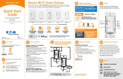
Accessory Dimmer can be wired with Wi-Fi Smart Dimmer (EWFD30) to provide multi-location ON/OFF/BRIGHT/DIM control. The Accessory Dimmer (EWACD) will need to be wired with the load controlling dimmer using a single 3-way wire.Dimmable seven step white LED display alongside push pad indicates selected light level (coordinates light level status with connected Wi-Fi Smart Dimmer)Your Accessory DimmerMust use with the Wi-Fi Smart Dimmer (EWFD30)FeaturesLight level may be adjusted with lights ON or OFF Press to brighten Press to dimTwo Location Control Installation (requires one Wi-Fi Smart Dimmer and one Accessory Dimmer)Operation instructionsMulti-location use onlyMust use with Wi-Fi Smart Dimmer (EWFD30) for multi-location controlPrior to installationOPERATION INSTRUCTIONS• Press ON button to turn lights ON at previously selected level• Press OFF button to turn lights OFF• The bottom LED indicates the dimmer is turned ON • W hen the lights are ON, press and hold the OFF button for 2 seconds until the LED indicator blinks After a 10 second delay, the lights will fade offFor color change kit installation instructions, see back pageInstall the Wi-Fi Smart Dimmer (EWFD30) using 3-way application instructions.12Install Accessory Dimmer (EWACD) through in-wall 3-way wiring with primary Wi-Fi S mart Dimmer.3Add the primary Wi-Fi Smart Dimmer (EWFD30) to the Brightlayer Home App.Accessory Dimmer (EWACD) will simply follow the commands of the Wi-Fi Smart Dimmer.3Tools neededAdditional system requirementsPhillips-head ScrewdriverWire cuttersTools required for installation (not included) for the Accessory Dimmer (EWACD):A 2.4GHz Wi-Fi network with high-speed internetIOS 12.0 or later or Android 8.0 or later mobile device. Note: Must be connected to Wi-Fi and Bluetooth A Brightlayer Home account set-up through the Brightlayer Home AppVoice controlw ith Alexa and Hey Google installation requiredSet schedules, groups, and scenesFor multi-location applications (3-way or 4-way), the Accessory Dimmer (EWACD) or a regular 3-way switch with one Wi-Fi Smart Dimmer (EWFD30) can be used.Neutral is requiredSafely leave roombefore lights turn offWi-Fi Smart Devices offer reliability with unbeatable ease o f setup. /smarthomeEWFSW15EWFTRCR15EWACDEWFFSC15Amazon, Alexa and all related logos are trademarks of , Inc. or its affiliates. Google and Google Play are trademarks of Google LLC. Wi-Fi CERTIFIED logo is a trademark of the Wi-Fi Alliance.Requires neutral for installationWARNINGS AND CAUTIONS • T urn OFF circuit breaker or remove fuse(s) and test that power is OFF before installation process • N ever wire any electrical device with power turned ON Wiring dimmer HOT may cause permanent damage to dimmer and void warranty • I f you are not sure about any part of these instructions, please contact a licensed electrician CAUTION• Use only with 120V/AC 60Hz• Do not exceed maximum rating of dimmer as indicated on the device • M ust be installed and used in accordance with all national and local electrical codes • I f a bare copper or green ground connection is not available in the wallbox, contact a licensed electrician for installation • U se only #14 or #12 copper wire rated for at least 75ºC with these devicesDO NOT USE WITH ALUMINUM WIREIMPORTANT: Accessory Dimmer (EWACD) will not work or will be damaged if wired incorrectly and warranty will be voided. Refer to wiring instructions provided.Once selected the devices would be displayed as shown below:Note: Now the user can utilize many features that are available such as creating schedules, scenes, preset light levels and minimum/maximum brightness settingsthrough the Brightlayer Home App.FCC STATEMENTThis device complies with Part 15 of the FCC Rules. Operation is subject to the following two conditions:1: This device may not cause harmful interference, and2: This device must accept any interference received, including interference that may cause undesired operation.NOTE: This equipment has been tested and found to comply with the limits for aClass B digital device, pursuant to Part 15 of the FCC Rules. These limits are designed to provide reasonable protection against harmful interference in a residentialinstallation. This equipment generates, uses and can radiate radio frequency energy and, if not installed and used in accordance with the instructions, may cause harmful interference to radio communications. However, there is no guarantee that interfer-ence will not occur in a particular installation. If this equipment does cause harmful interference to radio or television reception, which can be determined by turning the equipment off and on, the user is encouraged to try to correct the interference by one or more of the following measures:• Reorient or relocate the receiving antenna.• Increase the separation between the equipment and receiver.• Connect the equipment into an outlet on a circuit different from that to which the receiver is connected.• Consult the dealer or an experienced radio/TV technician for help.FCC CAUTION: Any changes or modifications not expressly approved by Eaton Wiring Devices could void the user’s authority to operate the equipment.This device complies with Industry Canada’s license-exempt RSSs. Operation is subject to the following two conditions:(1) This device may not cause interference; and(2) This device must accept any interference, including interference that may cause undesired operation of the device.EATON WIRING DEVICES LIMITED 2 YEAR WARRANTYEaton Wiring Devices warrants its Dimmer to be free of defects in materials and workmanship in normal use and service for a period of two years from date of original purchase. THIS TWO (2) YEAR LIMITED WARRANTY IS IN LIEU OF ALL OTHER WARRANTIES, OBLIGATIONS, OR LIABILITIES, EXPRESSED OR IMPLIED (INCLUDING ANY IMPLIED WARRANTY OF MERCHANTABILITY OR FITNESS FOR A PARTICULAR PURPOSE THAT IS IN DURATION IN EXCESS OF TWO YEARS FROM THE DATE OF ORIGINAL CONSUMER PURCHASE). NO AGENT, REPRESENTATIVE, OR EMPLOYEE OF EATON HAS AUTHORITY TO INCREASE OR ALTER THE OBLIGATIONS OF EATON UNDER THIS WARRANTY. To obtain warranty service for any properly installed Eaton Dimmer that proves defective in normal use send the defective Dimmer prepaid and insured to Quality Control Dept., Eaton Wiring Devices, 203 Cooper Circle, Peachtree City, GA 30269; in Canada: Eaton Wiring Devices, 5925 McLaughlin Road, Mississauga, Ontario L5R 1B8. Eaton will repair or replace the defective unit, at its option. Eaton will not be responsible under this warranty if examination shows that the defective condition of the unit was caused by misuse, abuse, improper installation, alteration, improper maintenance or repair of damage inTroubleshooting guideAccessory Dimmer color change kit installation instructionsSTEP 1 :Squeeze top tabs on either side of the deviceSTEP 2 :Pull faceplate offSTEP 3 :Line up all tabs and snap the faceplateWarrantyLED statusSet-up the Wi-Fi smart dimmer (EWFD30)Add the primary Wi-Fi Smart Dimmer (EWFD30) to theBrightlayer Home App, so that the Accessory Dimmer (EWACD) will simply follow the commands of the Wi-Fi Smart Dimmer.STEP 1 : Double click on the “ON” button on the Wi-Fi Smart Dimmer (EWFD30). Status LED on the Wi-Fi Smart Dimmer should be blinking cyan to indicate that the device is in set-up mode. If the status LED is not blinking, refer to the Troubleshooting guide.STEP 2 : Log in to your account on the Brightlayer Home App STEP 3 : Select “Devices” optionOnce initial device is installed, additional devices can be added using the global add (+) buttonNext click on “Add a Device” option shown in the screen belowSelect the device type to addHow to download the AppGet your Wi-Fi Smart Device running in 3 easy steps!STEP 3 (continued) :Amazon, Alexa and all related logos are trademarks of , Inc. or its affiliates. Google and Google Play are trademarks of Google LLC. Wi-Fi CERTIFIED logo is a trademark of the Wi-Fi Alliance.STEP 3 (continued) :SymptomPossible causeSolutionDevice doesn’t function. All LEDs are OFFA)B) C) Circuit breaker is OFF or trippedImproper wiring Defective dimmerA) B) C) Turn ON the circuit breakerCheck and correct wiring Replace dimmerOne of the LED indicators is blinking, but can’t control the load.Accessory dimmer (EWACD) is not connected to the Wi-Fi Smart Dimmer (EWFD30)Check wiring diagram Quick reference table for Wi-Fi Smart Dimmer (EWFD30) functionalityNOTE: Not all products include color change kits.Available in 3 different color change kitsFor more information, visit /smarthomeDownload the AppSearch and download the Brightlayer Home App via the App Store or Google Play.Select “Create an Account” to create an account by following the instructions on the screen.Fold in half vertically with page 1 on outside, then Z-fold in horizontal direction to final folded size of 3.4 in. W x 5.5 in. H with part number facing outward.。
PCI接口无线网卡:Asus WL-138g v2驱动:bcm43xx芯片组: Broadcom使用正常(笔者估计这是一块旧的Broadcom芯片,其实Broadcom芯片总体支持很差) Dlink DWL-AG530使用正常Dlink DWL-G520芯片组: Atheros扩展天线: RP-SMA使用正常Dlink DWL-G510芯片组: Ralink扩展天线: SMA-REV不能工作。
虽然支持Ralink芯片组.Foxconn WLL-3350驱动: rt2500MSI PC60G驱动: RT61芯片组: Ralink除了注入等部分功能,其余使用正常Netgear WG311T驱动: Madwifi-ng芯片组: AtherosExternal Antenna: RP-SMA ConnectorWorks perfectly out of the box. Injection works as Well.Netgear WPN311驱动: Madwifi-ng芯片组: Atheros扩展天线: RP-SMA包括注入都能完美工作SMC SMCWPCI-G芯片组: Atheros扩展天线: External SMA (detachable)包括注入都能完美工作基于Broadcom BCM4306 802.11b/g (rev 3)的无线网卡:Dell 1350 WLAN Mini-PCI 2.6.20-BT-PwnSauce-NOSMPHP Pavilion ZV5330usHP Pavilion zd8000Compaq Presario 2500驱动: bcm43xx只能监控,不能注入(笔者曾经用过,加-x 30和iwconfig rate 1M可以简单注入)基于Broadcom BCM4318 802.11b/g的无线网卡:驱动: bcm43xx可以监控,使用aircrack-ng0.9可支持简单的注入,键入命令:bt ~ # ifconfig eth0 upbt ~ # iwconfig eth0 mode Monitor channel然后使用1号和3号攻击模式IBM AR5212 802.11abg NIC (rev 01)驱动: AtherosIPW2100(小提示:IPW就是Intel Pro Wireless驱动: IPW2100只能监控,不能注入IPW2200驱动: IPW2200 (需要注入驱动补丁)只能监控,不能注入IPW3945驱动: IPW3945只能监控,不能注入IPW3945(另一版本IPW3945)Driver : IPWRAW,写一些命令后正常工作WN360G驱动: prism54Mini PCIe (内置笔记本MiniPCIE接口):Gigabit Atheros card正常工作Broadcom BCM4311 802.11b/g驱动: bcm43xx (bcmwl5.sys)只能监控,不能注入PCMCIA接口无线网卡:3COM 3CRWE154G72 v1驱动: prism54芯片组: Conexant PrismGT FullMAC注意: 有的版本不是此芯片组3COM 3CRPAG175B with XJACK Antenna驱动: Madwifi-ng芯片组: Atheros AR5212完美工作,使用起来就像教程中一样.AirLink101 AWLC4130驱动: Madwifi-ng芯片组: Atheros有人说100%兼容ASUS WL100G驱动: bcm43xx芯片组: Broadcom BCM43xx启动没找到Belkin F5D6020 v3驱动: Realtek芯片组: rtl8180包括注入完全兼容Belkin F5D7010 V1000驱动: bcm43xx芯片组: Broadcom BCM43xx没有完全测试玩Belkin F5D7010 V3000UK驱动: RT61芯片组: Unknown will update later (SORRY)可以监控,无法注入Belkin F5D7010 V5000驱动: Atheros芯片组: Atheros很好的工作了Belkin F5D7010 V6000驱动: RT61芯片组: Ralink改进驱动,作者没有写明是否正常工作Belkin F5D7011驱动: bcm43xx芯片组: Broadcom 4306启动正常,注入我自己的无线AP正常Buffalo WLI-CB-G54HP驱动: bcm43xx芯片组: Broadcom BCM43xx正常工作(笔者猜测这也是一张旧的Broadcom卡,因为新的支持的都不太好) Cisco AIR-PCM350驱动: airo芯片组: Cisco Aironet升级驱动可进入监控模式Cisco Aironet AIR-CB21AG-A-K9驱动: Madwifi-ng芯片组: Atheros作者未写明Dlink DW A-645驱动: Madwifi-ng芯片组: Atheros AR5416 a/b/g/n升级驱动Dlink DWL-650+驱动: acx100芯片组: Texas Instruments ACX100使用一些方法可以调用驱动Dlink DWL-G650驱动: Madwifi-ng芯片组: Atheros AR5212 a/b/g可以进入监控,注入作者未写明Dlink DWL-G650M芯片组: Atheros Communications, Inc. AR5005VL 802.11bg Wireless NIC (rev 01)Dlink DWL-G650+驱动: Ndiswrapper芯片组: Texas Instruments ACX100NdisWrapper不能用Aircrack-ng软件包(就是说基本Linux无望)D-Link WNA-1330驱动: Madwifi-ng芯片组: Atheros发现在监控模式下无法切回频道1正常工作,只能先退出监控模式.Enterasys Roamabout 802.11 DS High Rate驱动: orinoco_cs, wvlan_cs, wavelan_cs芯片组: Hermes I模式: 802.11b only (11Mbps)最新的驱动可以监控,但不能注入,注意以前驱动有个大bug.Gigabyte GN-WM01GT AirCruiserG Mach G驱动: madwifi-ng芯片组: Atheros模式:2.4Ghz 802.11b/g 108Mbps.除了在包注入时有点问题,其余完美的工作.Linksys WPC11v4驱动: Maxim芯片组: rtl8180包括注入均能完美的工作Linksys WPC11v4驱动: Philips SA2400芯片组: rtl8180Notes: Requires terminal input of iwconfig and dhcpcd wlan0包括注入均能正常的工作Linksys WPC54G v3驱动: bcm43xx芯片组: Broadcom Corporation BCM4318 [AirForce One 54g] 802.11g Wireless LAN Controller (rev 02)可以监控,无法注入Motorola WN825G v2驱动: bcm43xx芯片组: Broadcom 4306可以监控,注入未测试,估计和其它Broadcom网卡一样无法注入NetGear MA401驱动: HostAP芯片组: Prism 2你必须加载HostAP驱动进行注入.NetGear WPN511驱动: Madwifi-ng芯片组: Atheros包括注入均能工作,经过测试1-5攻击方式发现完美工作.NetGear WPN511 - Range Max驱动: Madwifi-ng芯片组: Atheros AR5212 a/b/g和大多说Atheros一样,可以工作NetGear WG511T驱动: Madwifi-ng芯片组: Atheros正常工作,支持全5种攻击方式,如果发现有问题可按下述命令试验:BT ~#airmon-ng stop ath0BT ~#airmon-ng start wifi0BT ~#ifconfig ath0 downBT ~#airmon-ng start ath1BT ~#airmon-ng start wifi0NetGear WAG511v2驱动: Madwifi-ng芯片组: AtherosNetGear WG511 v1驱动: prism54芯片组: Conexant PrismGT FullMAC注意: v2/v3版并不是这个芯片组包括注入均能完美工作。
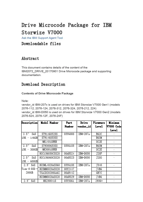
Drive Microcode Package for IBM Storwize V7000Ask the IBM Support Agent ToolDownloadable filesAbstractThis document contains details of the content of theIBM2072_DRIVE_20170901 Drive Microcode package and supporting documentation.Download DescriptionContents of Drive Microcode PackageNote:vendor_id IBM-207x is used on drives for IBM Storwize V7000 Gen1 (models 2076-112, 2076-124, 2076-312, 2076-324, 2076-212, 224)vendor_id IBM-D050 is used on drives for IBM Storwize V7000 Gen2 (models 2076-524, 2076-12F, 2076-24F)Level85Y5862v7.4.0.1 v6.3.0.04K BS** It is strongly recommended that customers with these drive model numbers (HUC106030CSS60, HUC106045CSS60, HUC106060CSS60) in their configuration, upgrade to this latest level of drive firmware.* If upgrading from 291E, please first upgrade to 2920 and then 2936. Please note: Ralston Peak 300 GB product_id=HUSML4030ASS60 is immune from this problem.2920 can be found on Fix Central in thispackage: StorageDisk-2076-DriveMicrocode-20121210Important Information:Drive Firmware upgrades are not supported on SAN Volume Controller or Storwize V7000 systems running V6.1 or V6.2. Please refer to the following Flash for more information.Drive Firmware Upgrades May Result in Temporary Loss of Host Access to Volumes on SAN Volume Controller and Storwize V7000Please refer to the svctask applydrivesoftware CLI command help in the IBM Storwize V7000 Information Center for installation instructions regarding this Drive Microcode Package.To check that your drive firmware is up to date download and run the Software Upgrade Test UtilityKeep Informed of UpdatesKeep up to date with the latest V7000 information by subscribing toreceive support notifications.Legal AgreementTHE FOLLOWING DOWNLOADS CONTAIN UPDATES AND FIXES TO CODE THAT WAS ORIGINALLY PROVIDED WITH THE IBM STORWIZEV7000 SOLUTION, INCLUDING THE IBM STORWIZE V7000 SOFTWARE. THE UPDATED CODE IS SUBJECT TO THE TERMS AND CONDITIONS OF THE LICENSE AGREEMENTS APPLICABLE TO THE CODE THAT IT UPDATES INCLUDING, AS APPROPRIATE, THE IBM AGREEMENT FOR MACHINE CODE AND IBM INTERNATIONAL PROGRAM LICENSE AGREEMENT. BY DOWNLOADING THE FOLLOWING FILES, YOU ARE AGREEING TO TREAT THE UPDATED CODE IN ACCORDANCE WITH THE APPLICABLE LICENSE AGREEMENTS.Download packageDESCRIPTION DOCUMENTATION LABEL DownloadOptionsPlatform IBMStorwize V7000Version IndependentEnglishByte Size 96217827Date 02 Sep 2017DriveMicrocodePackageHTTP。
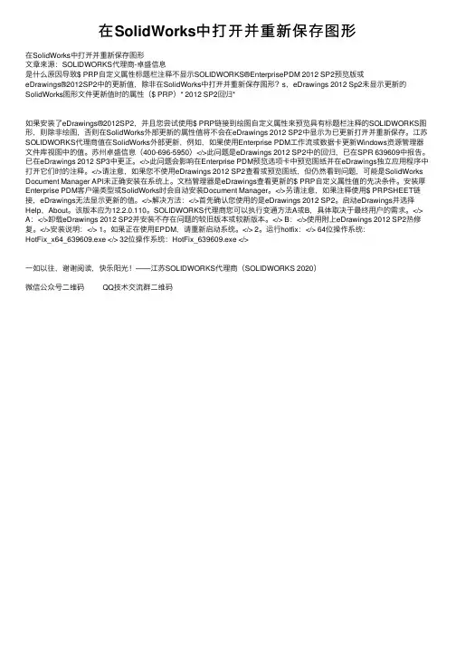
在SolidWorks中打开并重新保存图形在SolidWorks中打开并重新保存图形⽂章来源:SOLIDWORKS代理商-卓盛信息是什么原因导致$ PRP⾃定义属性标题栏注释不显⽰SOLIDWORKS®EnterprisePDM 2012 SP2预览版或eDrawings®2012SP2中的更新值,除⾮在SolidWorks中打开并重新保存图形?s,eDrawings 2012 Sp2未显⽰更新的SolidWorks图形⽂件更新值时的属性($ PRP)* 2012 SP2回归*如果安装了eDrawings®2012SP2,并且您尝试使⽤$ PRP链接到绘图⾃定义属性来预览具有标题栏注释的SOLIDWORKS图形,则除⾮绘图,否则在SolidWorks外部更新的属性值将不会在eDrawings 2012 SP2中显⽰为已更新打开并重新保存。
江苏SOLIDWORKS代理商值在SolidWorks外部更新,例如,如果使⽤Enterprise PDM⼯作流或数据卡更新Windows资源管理器⽂件库视图中的值。
苏州卓盛信息(400-696-5950)</>此问题是eDrawings 2012 SP2中的回归,已在SPR 639609中报告。
已在eDrawings 2012 SP3中更正。
</>此问题会影响在Enterprise PDM预览选项卡中预览图纸并在eDrawings独⽴应⽤程序中打开它们时的注释。
</>请注意,如果您不使⽤eDrawings 2012 SP2查看或预览图纸,但仍然看到问题,可能是SolidWorks Document Manager API未正确安装在系统上。
⽂档管理器是eDrawings查看更新的$ PRP⾃定义属性值的先决条件。
安装厚Enterprise PDM客户端类型或SolidWorks时会⾃动安装Document Manager。
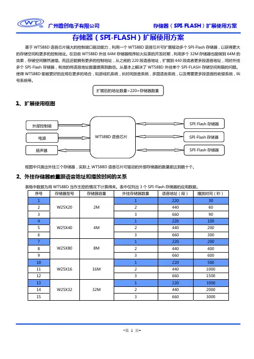
存储器(SPI-FLASH)扩展使用方案基于WT588D 语音芯片强大的控制端口驱动能力,利用一个WT588D 语音芯片可扩展驱动多个SPI-Flash 存储器,以获得更大的存储空间和更多的控制地址。
在目前WT588D 外挂64M 存储器程序如火似荼的开发时期,利用多个32M 存储器也能做到64M 的效果,存储空间骤然递增。
而且还能拥有更多的控制地址,从之前的220段语音地址,扩展到440段或者更多段语音地址,同时外挂多个SPI-Flash 存储器,有效的将语音地址数量提高到数倍。
从基本上解决了WT588D 外挂单个SPI-FLASH 存储空间有限的问题。
使得WT588D能被更好的应用在更多的场合,如游戏机系统,长时间放音系统,多国语言系统,以及需要更多段语音的收银系统,叫号系统等。
1、扩展使用框图框图中只画出外挂三个存储器,实际上WT588D 语音芯片可驱动的外部存储器的数量能达到数十个。
2、外挂存储器数量跟语音地址和播放时间的关系表格中数据为用WT588D 当作主控的情况下计算得来。
表中仅列出3个SPI-Flash 存储器的应用数据。
序号 存储器型号存储器容量外挂存储器数量语音地址(段)播放时间(秒)1 W25X202M1 220 302 2 440 603 3 660 904 W25X404M1 220 100 52 440 200 63 660 300 7 W25X808M1 220 200 82 440 400 93 660 600 10 W25X1616M1 220 500 112 440 1000 123 660 1500 13 W25X3232M1 220 1000 142 440 2000 15366030003、扩展电路图3.1、开关切换模式控制:此电路为外挂6个SPI-FLASH方案,SPI-FLASH的DO、DI、CS、CLK级联接到WT588D语音芯片的P13(DO)、P14(DI)、P15(CS)、P16(CLK)。
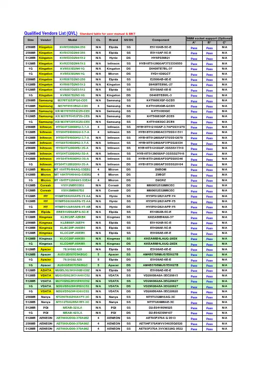
Qualified Vendors List (QVL) Standard table for user manual & MKTA*B*C*256MB Kingston KVR533D2N4/256N/A Elpida SS E5116AB-5C-E Pass Pass N/A 256MB Kingston KVR533D2N4/256N/A Elpida SS E5116AF-5C-E Pass Pass N/A 512MB Kingston KVR533D2N4/512N/A Hynix DS HY5PS56821Pass Pass N/A 512MB Kingston KVR533D2N4/512N/A Infineon SS HYB18T512800AF3733336550Pass Pass N/A 1G Kingston KVR533D2N4/1G N/A Kingston DS D6408TE7BL-37Pass Pass N/A 1G Kingston KVR533D2N4/1G N/A Micron DS 5YD11D9GCT Pass Pass N/A 256MB Kingston KVR667D2N5/256N/A Elpida SS E2508AB-6E-E Pass Pass N/A 512MB Kingston KVR667D2N5/512N/A Kingston SS D6408TE8WL-27Pass Pass N/A 512MB Kingston KVR667D2E5/512N/A Elpida SS E5108AE-6E-E Pass Pass N/A 1G Kingston KVR667D2N5/1G N/A Kingston DS D6408TE8WL-3Pass Pass N/A 256MB Samsung M378T3253FG0-CD5N/A Samsung SS K4T56083QF-GCD5Pass Pass N/A 512MB SamsungM378T6553BG0-CD54Samsung SS K4T51083QB-GCD5Pass Pass N/A 512MB Samsung KR M378T6553CZ0-CE6N/A Samsung SS K4T51083QC Pass Pass N/A 512MB Samsung KR M378T6453FZ0-CE6N/A Samsung DS K4T56083QF-ZCE6Pass Pass N/A 1G Samsung KR M378T2953CZ0-CE6N/A Samsung SS K4T51083QC-ZCE6Pass Pass N/A 256MB Infineon HYS64T32000HU-3.7-A 4Infineon SS HYB18T512160AF-3.7AFSS31270Pass Pass N/A 512MB Infineon HYS64T64000GU-3.7-A 4Infineon SS HYB18T512800AC37SSS11511Pass Pass N/A 512MB Infineon HYS64T64000HU-3.7-A N/A Infineon SS HYB18T512800AF37SSS12079Pass Pass N/A 512MB Infineon HYS64T64000HU-3.7-A N/A Infineon SS HYB18T512800AF37FSS29334Pass Pass N/A 256MB Infineon HYS64T32000HU-3S-A N/A Infineon SS HYB18T512160AF-3SSSS17310Pass Pass N/A 512MB Infineon HYS64T32000HU-3S-A N/A Infineon SS HYB18T5128000AF-3SSSS27416Pass Pass N/A 512MB Infineon HYS64T64000HU-3S-A N/A Infineon SS HYB18T512800AF3SFSS05346Pass Pass N/A 1G Infineon HYS64T128020HU-3S-AN/A Infineon DS HYB18T512800AF3SSSS28104Pass Pass N/A 512MB Micron MT 16HTF6464AG-53EB2 4Micron DS D9BOM Pass Pass N/A 512MB Micron MT 16HTF6464AG-53EB24Micron DS Z9BQT Pass Pass N/A 1G Micron MT 16HTF12864AY-53EA14Micron DS D9CRZ Pass Pass N/A 512MB Corsair VS512MB533D2N/A Corsair DS MIII0052532M8CEC Pass Pass N/A 512MB Corsair VS512MB667D2N/A Corsair DS MIII0052532M8CEC Pass Pass N/A 512MB HY HYMP564U64AP8-Y4 AA N/A Hynix SS HY5PS12821AFP-Y4Pass Pass N/A 512MB HY HYMP564U64AP8-Y5 AA N/A Hynix SS HY5PS12821AFP-Y5Pass Pass N/A 1G HY HYMP512U64AP8-Y5 AB N/A Hynix DS HY5PS12821AFP-Y5Pass Pass N/A 512MB Elpida EBE51UD8ABFA-5C-E N/A Elpida SS E5108AB-5C-E Pass Pass N/A 512MB Kingmax KLBC28F-A8KB4N/A Kingmax SS KKEA88B4IAK-37Pass Pass N/A 256MB Kingmax KLBB68F-36EP4N/A Elpida SS E5116AB-5C-E Pass Pass N/A 512MB Kingmax KLBC28F-A8EB4N/A Elpida SS E5108AE-5C-E Pass Pass N/A 512MB Kingmax KLCC28F-A8EB5N/A Elpida SS E5108AE-6E-E Pass Pass N/A 512MB Kingmax KLCC28F-A8KB5N/A Kingmax SS KKEA88B4LAUG-29DX Pass Pass N/A 1G Kingmax KLCD48F-A8KB5N/A Kingmax DS KKEA88B4LAUG-29DXPass Pass N/A 512MB Apacer 78.91092.420N/A Elpida SS E5108AE-6E-E Pass Pass N/A 512MB Apacer AU512E667C5KBGC5Apacer SS AM4B5708MIJS7E0627BPass Pass N/A 1G Apacer 78.01092.4205Elpida DS E5108AE-6E-E Pass Pass N/A 1G Apacer AU01GE667C5KBGC 5Apacer DS AM4B5708MIJS7E0627BPass Pass N/A 512MB ADATA M20EL5G3H3160B1C0Z N/A Elpida SS E5108AE-6E-E Pass Pass N/A 512MB VDATA M2GVD5G3H31A4I1C52N/A VDATA SS VD29608A8A-3EC20615Pass Pass N/A 512MB VDATA M2YVD5G3H31P4I1C52N/A VDATA SS VD29608A8A-3EG20627Pass Pass N/A 1G VDATA M2GVD5G3I41P6I1C52N/A VDATA DS VD29608A8A-3EG20627Pass Pass N/A 1G VDATA M2GVD5G3I41C4I1C52N/A VDATA DS VD29608A8A-3EC20620Pass Pass N/A 256MB Nanya NT256T64UH4A1FY-3C N/A Nanya SS NT5TU32M16AG-3C Pass Pass N/A 512MB Nanya NT512T64U88A1BY-3CN/A Nanya SS NT5TU64M8AE-3C Pass Pass N/A 512MB PQI MEAB-323LA N/A PQI SS D2-E04180W025Pass Pass N/A 1G PQI MEAB-423LA N/A PQI DS D2-E04230W107Pass Pass N/A 512MB AENEON AET660UD00-370A98Z 4AENEON SS AET93F370A G 0513Pass Pass N/A 256MB AENEON AET560UD00-370A98Z 4AENEON SS AET94F370AWVV34635G0520Pass Pass N/A 512MBAENEONAET660UD00-370A98Z4AENEONSSAET93F370A 3VV36328G 0522PassPassN/ASize Vendor Model CL Brand SS/DS Component DIMM socket support (Optional)512MB AENEON AET660UD00-370A98X N/A AENEON SS AET93F370A 0518Pass Pass N/A 512MB AENEON AET660UD00-370A88S N/A AENEON DS AET82F370A 0550Pass Pass N/A 1G AENEON AET760UD00-370A98Z N/A AENEON DS AET93F370A 0551Pass Pass N/A 1G AENEON AET760UD00-370A98S N/A AENEON DS AET92F370A 0606Pass Pass N/A 2G AENEON AET860UD00-370A08X N/A AENEON DS AET03F370AFVV26176G 0542Pass Pass N/A 512MB AENEON AET660UD00-30DA98Z N/A AENEON SS AET93F30DA 0552Pass Pass N/A 1G AENEON AET760UD00-30DA98Z N/A AENEON DS AET93F30DA8EE47414G 0540Pass Pass N/A 512MB AENEON AET660UD00-30DA98Z N/A AENEON SS AET93F300A 0606Pass Pass N/A 1G AENEON AET760UD00-30DA98Z N/A AENEON DS AET93F30DA 0604Pass Pass N/A512MB VERITECHGTP512HLTM46DG N/AVERITECHSS VTD264M8PC6G01A164129621Pass Pass N/A1G VERITECHGTP01GHLTM56DG N/AVERITECHDS VTD264M8PC6G01A164129621Pass Pass N/A512MB VERITECHGTP512HLTM45EG N/AVERITECHSS VTD264M8PC6G01A164129621Pass Pass N/A1G VERITECHGTP01GHLTM55EG N/AVERITECHDS VTD264M8PC6G01A164129621Pass Pass N/A512MB GEIL GX21GB5300DC4GEIT SS Heat-Sink Package Pass Pass N/A 512MB Century CENTURY 512MB N/A Nanya SS NT5TU64M8AE-3C Pass Pass N/A 512MB Century CENTURY 512MB N/A Hynix SS HY5PS12821AFP-Y5Pass Pass N/A 1G Century CENTURY 1G N/A Hynix DS HY5PS12821AFP-Y5Pass Pass N/A 1G Century CENTURY 1G N/A Nanya DS NT5TU64M8AE-3C Pass Pass N/A 512MB KINGBOX512MB 667MHz N/A KINGBOX SS EPD264082200-4Pass Pass N/ANote:A* : Supports one module inserted in any slot as Single-channel memory configurationB* : Supports one pair of modules inserted into eithor the blue slots or the black slots as one pair of Dual-channel memory configurationC* : Supports 4 modules inserted into both the blue and black slots as two pairs of Dual-channel memory configuration。

1122334455667788DDCCBBAAReference Designs ARE PROVIDED "AS IS" AND "WITH ALL FAULTS. Arduino SA DISCLAIMS ALL OTHER WARRANTIES, EXPRESS OR IMPLIED, REGARDING PRODUCTS, INCLUDING BUT NOT LIMITED TO, ANY IMPLIED WARRANTIES OF MERCHANTABILITY OR FITNESS FOR A PARTICULA R PURPOSE.Arduino SA may make changes to specifications and product descriptions at any time, without notice. The Customer must not rely on the absence or characteristics of any features or instructions marked "reserved" or "undefined".Arduino SA reserves these for future definition and shall have no responsibility whatsoever for conflicts or incompatibilities arising from future changes to them. The product information on the Web Site or Materials is subject to change without notice.Do not finalize a design with this info. ARDUINO and other Arduino brands and logos and Trademarks of Arduino SA. All Arduino SA Trademarks cannot be used without owner's formal permission.11UNO R4 MINIMA ABX00080V1.04/24/20233:04:30 PM Title:ID:Date:Version:Sheet of Time:Silvio NavarettiAuthor:RevAuthor:Silvio NavarettiTOP.SchDocFile:330R14330R15DL1KPT-1608YC YELLOWDL2KPT-1608YC TX LED RX LED MICROCONTROLLER330R16DL3HSMG-C190POWER LED+5VP012YELLOWFiducial_1Fiducial_2GREENP400/GTIOC6A1P401/GTIOC6B/CTX02P402/CRX03VBATT 4VCL5P215 INPUT ONL Y/XCIN 6P214 INPUT ONL Y/XCOUT7VSS 8P213/GTIOC0A/XTAL 9P212/GTIOC0B/EXTAL10VCC 11P411/GTIOC6A12P410/GTIOC6B 13P409/GTIOC5A/USB_EXICEN 14P408/GTIOC5B/USB_ID15P407/USB_VBUS/ADTRG016VSS_USB 17P915/USB_DM 18P914/USB_DP19VCC_USB20VCC_USB_LDO 21P20622GTIOC4A/P20523GTIOC4B/P20424RES25MD/P20126NMI/INPUT ONL Y P20027GTIOC7A/P30428GTIOC7B/P30329GTIOC4A/P30230GTIOC4B/P30131P300/GTIOC0A/TCK/SWCLK 32P108/GTIOC0B/TMS/SWDIO 33CTX0/TDO/SWO/GTIOC1A/P10934CRX0/TDI/GTIOC1B/P11035GTIOC3A/P11136GTIOC3B/P11237GTIOC2A/P11338VCC 39VSS40GTIOC0A/P10741GTIOC0B/P10642GTIOC1A/P10543GTIOC1B/P10444GTIOC2A/AN019/P10345ADTRG0/GTIOC2B/AN020/P10246GTIOC5A/AN021/P10147GTIOC5B/AN022/P10048GTIOC2A/AN016/P50049GTIOC2B/AN017/P50150GTIOC3B/AN018/P50251AN010/P01552DA0/AN009/P01453VREFL/AN008/P01354VREFH/AN007/P01255AVCC056AVSS057VREFL0/AN006/P01158P010/AN005/VREFH059AN004/P00460AN003/P00361AN002/P00262AN001/P00163AN000/P00064U1R7FA4M1AB3CFM#AA0USB_D_N USB_D_P15pFC113N C2N C4Y1FTX16.000M12SM3S-30/3015pFC3RESET +5V 4.7µFC4100nF C5100nFC6VCC_USB is the output of theinternal USB LDO providing 3V3 to the peripheralRefer to figure 26.4 page 555 of the user manual4.7µFC7AREF+5VL1BLM18PG471SN1D5.1kR4VREFH01µFC9L2BLM18PG471SN1D100nF C8VCL is the output of the internal LDO4.7µFC11RESET PUSHBUTTONHEADERS+5V+5VUSB5.1kR1 5.1kR25.1kR3SCL18SDA 17AREF 16GND 15D13/SCK 14D12/MISO 13D11/MOSI 12D10/CS11D910D89D78D67D56D45D34D23D1/TX 2D0/RX1JDIGITAL20TW-994C2DNP12345PB11571636-3AREFNC 1IOREF 2RESET 33V345V5GND6GND7VIN 8A09A110A211A312A413A514JANALOG20TW-995RESET RESET112233445566J1PH2-06-UA+5V P013USB CONNECTORSHIELD1GNDB12VBUS B9SBU2B8D-B7D+B6CC2B5VBUS B4GND B1GND A12VBUSA9SBU1A8D-A7D+A6CC1A5VBUS A4GND A1FIXING A12A1B12B1SHIELD2SHIELD3SHIELD4J3CX90B-16P VBUS_CONN CC1USB_D_PUSB_D_N D-USB USB_D_N USBUSB_D_P D+CC2GND21MR231kV4.7nFC21ESDPROTECTION2341D4PRTR5V0U2X,215SHIELD2CC RESISTORS CC2CC15.1kR24 5.1kR25123J419TW-746+5VUSB LDO OUTPUT+3V3100nF C10+5VVINDC SHIELD2USB_D_N USB_D_P SWD CONNECTOR12345678910J2HPH2-A-10-SGARESET +5VRXTX RTS CTSSCI15.1kR75.1k R85.1kR9P012P0135.1kR5 5.1kR6INPUT ONLY+3V3VIN DAC OPAMP+P000_AN00_AMP+OPAMP-OPAMP OUT P014_AN09_DAC P001_AN01_AMP-P002_AN02_AMPO P101_AN21_SDA P100_AN22_SCL P000_AN00_AMP+P001_AN01_AMP-P002_AN02_AMPOP014_AN09_DACP100_AN22_SCL P101_AN21_SDA P100_AN22_SCL P101_AN21_SDAP301_SCI2_RXDP302_SCI2_TXD P301_SCI2_RXD P302_SCI2_TXD I2C PULLUPSNOT MOUNTEDP105_IRQ00_GPT1_A P105_IRQ00_GPT1_A DL4KPT-1608YC YELLOW 330R17SCK LEDP104_IRQ01_GPT1_B P104_IRQ01_GPT1_B P103_SPI0_SSL_GPT2_A_CAN0_TX P103_SPI0_SSL_GPT2_A_CAN0_TX P102_SPI0_RSPCK_GPT2_B_CAN0_RX P102_SPI0_RSPCK_GPT2_B_CAN0_RX P106_GPT0_BP106_GPT0_B P107_GPT0_A P107_GPT0_AP304_GPT7_A P304_GPT7_AP303_GPT7_B P303_GPT7_B P112_GPT3_BP112_GPT3_B P109_SCI9_TXD P109_SCI9_TXD P109_SCI9_TXDP110_SCI9_RXD P110_SCI9_RXD P 110_S C I 9_R X DP111_GPT3_A P111_GPT3_A P 111_G P T 3_AP111_GPT3_AP108_SWDIO P300_SWCLK P108_SWDIOP300_SWCLK P501_SCI1_TXD P502_SCI1_RXDP501_SCI1_TXDP502_SCI1_RXD +5VMD MDVUSBDCJACKBUCKCONVERTERSCHOTTKY FORREVERSE POLARITY PROTECTIOND3PMEG6020AELRXD2PMEG6020AELRXSS 1SYNC2BOOT 3VIN 4PHASE5PGND 6EN 7PG 8VCC 9FB 10COMP11FS12GNDPAD13U2ISL854102FRZ-T +5V2.3A 10µH L3PMF42-103MN100nF C1225V 22µF C130R12100kR1325V22µFC1825V 22µF C1525V 22µF C1633pF C1425V 22µF C171µFC2025V22µF C1913.7kR180R20249kR19100kR21100kR221nFC22100pFC23+5V+5V VUSB VUSB VUSBVUSB VUSB 0R11100k 0.1%R1013.7k 0.1%R26+5VSCHOTTKY FOR USB OVERVOL TAGE PROTECTIONP204LOVE。
Freescale Semiconductor, er’s Guide1IntroductionThe Freescale Freedom development board is an evaluation and development tool ideal for rapid prototyping ofmicrocontroller-based applications. The hardware design is form-factor compatible with popular third-party hardware designed to work with Arduino™ and Arduino-compatible boards.The Freescale KL27Z Freedom board (FRDM-KL27Z) is a simple, yet sophisticated design featuring a Kinetis L series microcontroller KL27Z,a 3.3V microcontroller built on the ARM® Cortex®-M0+ core.The Kinetis L series is the most scalable portfolio oflow-power, robust, mixed signal 32-bit ARM Cortex-M0+ MCUs running up to 48 MHz in the industry. It supports power supply voltage range from 1.71V to 3.6V , ambient operating temperature ranges from -40°C to 105°C and includes up to 64 KB flash.The FRDM-KL27Z includes the Freescale open standard embedded serial and debug adapter known as OpenSDA. This circuit offers the user several options for serial communications, flash programming and run-control debugging.Document Number:FRDMKL27ZUGRev. 0, 02/2015Contents1.Introduction . . . . . . . . . . . . . . . . . . . . . . . . . . . . . . . . . 12.Reference documents . . . . . . . . . . . . . . . . . . . . . . . . . . 23.Getting started . . . . . . . . . . . . . . . . . . . . . . . . . . . . . . . 24.FRDM-KL27Z hardware overview . . . . . . . . . . . . . . . 25.FRDM-KL27Z hardware description . . . . . . . . . . . . . 45.1.Power supply . . . . . . . . . . . . . . . . . . . . . . . . . . . . . . . . 45.2.Serial and debug adapter (OpenSDA) . . . . . . . . . . . . . 65.3.Debugging interface . . . . . . . . . . . . . . . . . . . . . . . . . . 75.4.Virtual serial port . . . . . . . . . . . . . . . . . . . . . . . . . . . . . 75.5.Clock source . . . . . . . . . . . . . . . . . . . . . . . . . . . . . . . . 75.6.Serial port . . . . . . . . . . . . . . . . . . . . . . . . . . . . . . . . . . 85.7.Reset . . . . . . . . . . . . . . . . . . . . . . . . . . . . . . . . . . . . . . 85.8.Debug . . . . . . . . . . . . . . . . . . . . . . . . . . . . . . . . . . . . . 85.9.Capacitive touch slider . . . . . . . . . . . . . . . . . . . . . . . . 85.10.6-axis accelerometer and magnetometer . . . . . . . . . . . 95.11.RGB LED . . . . . . . . . . . . . . . . . . . . . . . . . . . . . . . . . 105.12.Input/output headers . . . . . . . . . . . . . . . . . . . . . . . . . 115.13.Arduino compatibility . . . . . . . . . . . . . . . . . . . . . . . . ing the FRDM-KL27Z with EEMBC ULPBench . 126.1.Hardware modifications required for EnergyMonitor 126.2.Programming the ULPBench device software . . . . . 126.3.Hardware configuration . . . . . . . . . . . . . . . . . . . . . . . 126.4.EnergyMonitor connections . . . . . . . . . . . . . . . . . . . 137.Revision history . . . . . . . . . . . . . . . . . . . . . . . . . . . . . 13FRDM-KL27Z User’s GuideReference documentsThere are also many software development tool options available to the user. Choices include Kinetis Design Studio (KDS), IAR Embedded Workbench, Keil MDK featuring the µVision IDE, etc.All of these features combine to give users the freedom needed to rapidly prototype many embedded designs: a powerful microcontroller built on a very low-power core and SoC platform, easy-access to I/O with a large ecosystem of compatible hardware, a flexible programming and debug interface, and a large ecosystem of software development environments.2Reference documents•OpenSDA User’s Guide: A guide for users of the OpenSDA embedded circuit•KL27 Sub-Family Reference Manual: A reference manual for KL27 sub-family devices•Arduino Overview: A guide to the Arduino platform•Arduino Uno: A guide to Arduino Uno revision3Getting startedRefer to the FRDM-KL27Z Quick Start Package for step-by-step instructions for getting started with the freedom board. See the “Jump Start Your Design” section at /FRDM-KL27Z for the Quick Start Package and software lab guides.4FRDM-KL27Z hardware overviewThe FRDM-KL27Z hardware is a Freescale Freedom development board assembled with the following features:•Kinetis L series KL27 family MCU MKL27Z64VLH4 in an 64 LQFP package•On-board serial and debug adapter (OpenSDA)•I/O headers for easy access to MCU I/O pins•Freescale inertial sensor, MMA8451Q, Magnetometer MAG3110•Capacitive touch slider•Reset pushbutton•NMI and LLWU buttons•RGB LED•Infrared communication•Thermistor sensor•Supports the EEMBC ULPBench benchmarkFigure1 shows a block diagram of the FRDM-KL27Z board.FRDM-KL27Z hardware overviewFigure1. FRDM-KL27Z block diagramThe FRDM-KL27Z features two microcontrollers (MCUs): the target MCU and a serial and debug adapter (OpenSDA) MCU. The target MCU is a Kinetis series KL27 family device, the KL27Z64VLH4. The OpenSDA MCU is a Kinetis K series K20 family device, the K20DX128VFM5.Features of the KL27Z64VLH4 target MCU include:•32-bit ARM Cortex-M0+ core—Up to 48 MHz operation—Single-cycle fast I/O access port•Memories—64 KB flash—16 KB SRAM—16 KB ROM with build-in bootloader—32 bytes regfile•System integration—4-channel DMA controller—Watchdog—Low-leakage wakeup unit—SWD debug interface and Micro Trace Buffer—Bit Manipulation Engine•Clocks—48 MHz high accuracy internal reference clock—8/2 MHz low power internal reference clockFRDM-KL27Z hardware description—32-40 kHz, or 3-32 MHz crystal oscillator—1 kHz LPO clock•Analog peripherals—16-bit SAR ADC with internal voltage reference, up to 17 channels—High-speed analog comparator containing a 6-bit DAC and programmable reference input—1.2 V voltage reference (Vref)•Communication peripherals—USB full-speed slave controller supporting crystal-less recovery—Two 16-bit SPI modules—One UART module supporting ISO7816—Two LPUART modules—Two I2C modules supporting up to 1 Mbit/s—One FlexIO module•Timers—One 6-channel Timer/PWM module—Two 2-channel Timer/PWM modules—One low-power timer—Periodic interrupt timer—Real-time clock•Security—80-bit unique identification number per chip•Human-Machine Interfaces (HMI)—Up to 54 general purpose input/output (GPIO)—GPIO interrupt—External input pin for LLWU in LLS and VLLSx mode5FRDM-KL27Z hardware description5.1Power supplyThe FRDM-KL27Z offers a design with multiple power supply options. It can be powered from the USB connector, battery on the board, the VIN pin on the I/O header, or an off-board 1.71-3.6V supply from the 3.3V pin on the I/O header. The USB and VIN supplies are regulated on-board using a 3.3V linear regulator to produce the main power supply. The other two sources are not regulated on-board. Figure2 shows the schematic drawing for the power supply inputs and the on-board voltage regulator.FRDM-KL27Z hardware descriptionFigure2. FRDM-KL27Z power supplyTable 1 provides the operational details and requirements for the power supplies.NOTEThe OpenSDA circuit is only operational when a USB cable is connected and supplying power to J13. However, the protection circuitry is in place to allow multiple sources to be powered at once.Table 1. Tower supply requirementsSupply Source Valid RangeOpenSDA Operational?Regulated On-board?OpenSDA USB (J13)5V Yes Yes Mini USB(J10)5V No Yes P5V0-9V0_VIN Pin on I/O header4.3-9V No Yes P3V3 Pin on I/O header1.71-3.6V No No Battery2-3.6VNoNoTable 2. FRDM-KL27Z power suppliesPower Supply Name DescriptionP5V0-9V0_VIN Power supplied from the V IN pin of the I/O headers (J3 pin 16). P5V_SDA Power supplied from the OpenSDA USB connector (J13). P5V_KL27ZPower supplied from the Mini USB connector (J10).FRDM-KL27Z hardware descriptionNOTESJ9 and J17 are not populated by default. The two pins of these headers are in parallel with 0 Ω resistors. In addition, J17 is also in parallel with a 10 Ω resistor. To measure the energy consumption of the KL27Z, either avoltmeter or an ammeter may be used. To use a voltmeter, R2 (0 Ω) must be removed before connecting the voltmeter probes to the pins of J17. Both R1 and R2 (10 Ω) must be removed to measure current with an ammeter. For the OpenSDA MCU, energy consumption can be measured by removing R4 (0 Ω) and connecting ammeter probes to the pins of J9.5.2Serial and debug adapter (OpenSDA)OpenSDA is an open-standard serial and debug adapter. It bridges serial and debug communications between a USB host and an embedded target processor as shown in Figure 3. The hardware circuit is based on a Freescale Kinetis K20 family MCU with 128 KB of embedded flash and an integrated USB controller. OpenSDA features a mass storage device (MSD) bootloader, which provides a quick and easy mechanism for loading different OpenSDA Applications such as flash programmers, run-control debug interfaces, serial-to-USB converters, and more. Two or more OpenSDA applications can run simulta-neously. For example, run-control debug application and serial-to-USB converter runs in parallel to pro-vide a virtual COM communication interface while allowing code debugging via OpenSDA with just a single USB connection. These two applications are provided in a single code package. Refer to theOpenSDA User’s Guide for more details.Figure 3. OpenSDA block diagramP3V3_VREG Regulated 3.3V supply . Sources power to the P3V3 supply rail through an optional back drive protection Schottky diode.P3V3Main supply rail for the FRDM-KL27Z. Can be sourced from P3V3_VREG.P3V3_KL27Z KL27Z MCU power supply. Header J17 provides a convenient means for KL27Z energy consumption measurements.P3V3_SDAOpenSDA circuit power supply.Table 2. FRDM-KL27Z power suppliesFRDM-KL27Z hardware description OpenSDA is managed by a Kinetis K20 MCU built on the ARM Cortex-M4 core. The OpenSDA circuit includes a status LED (D8) and a RESET pushbutton (SW2). The pushbutton asserts the Reset signal to the KL27Z target MCU. It can also be used to place the OpenSDA circuit into Bootloader mode by holding down the RESET pushbutton while plugging the USB cable to USB connector J13. Once the OpenSDA enters bootloader mode, other OpenSDA applications such as debug app can be programmed.SPI and GPIO signals provide an interface to the SWD debug port of the KL27Z. Additionally, signal connections are available to implement a UART serial channel. The OpenSDA circuit receives power when the USB connector J13 is plugged into a USB host.5.3Debugging interfaceSignals with SPI and GPIO capability are used to connect directly to the SWD of the KL27Z. These signals are also brought out to a standard 10-pin (0.05”) Cortex Debug connector (J11) as shown in Figure4. It is possible to isolate the KL27Z MCU from the OpenSDA circuit and use J11 to connect to an off-board MCU. To accomplish this, cut the trace between pin1 and pin2 of J18 on bottom layer. This will disconnect the SWD_CLK pin to the KL27Z so that it will interfere with the communications to an off-board MCU connected to J11.Figure4. SWD debug connector to KL27Z5.4Virtual serial portA serial port connection is available between the OpenSDA MCU and LPUART0 pin PTA1(TXD) and PTA2 (RXD) of KL27Z. Several of the default OpenSDA Applications provided by Freescale, including the MSD Flash Programmer and the P&E Debug Application, provide a USB Communications Device Class (CDC) interface that bridges serial communications between the USB host and this serial interface on the KL27Z.5.5Clock sourceThe Kinetis KL27 microcontrollers feature an on-chip oscillator compatible with input crystal: 32 to 40 KHz or 3 to 32 MHz. The KL27Z on the FRDM-KL27Z is clocked from the internal clock LIRC (2 MHz/8 MHz) or HIRC (48 MHz), and on-board 32768 Hz crystal for the RTC clock source.FRDM-KL27Z hardware description5.6Serial portThe serial port interface signals used with OpenSDA are LPUART0 pin PTA1 (TXD) and PTA2 (RXD). These signals are also connected to I/O header J1.5.7ResetThe RESET signal on the KL27Z is connected externally to a pushbutton, SW2. The reset button can be used to force an external reset event in the target MCU. The reset button can also be used to force the OpenSDA circuit into bootloader mode when plugging the USB cable to J13. Refer to Section5.2, “Serial and debug adapter (OpenSDA)” for more details.5.8DebugThe sole debug interface on all Kinetis L series devices is a Serial Wire Debug (SWD) port. The primary controller of this interface on the FRDM-KL27Z is the onboard OpenSDA circuit. However, a 2x5-pin (0.05”) Cortex Debug connector, J11, provides access to the SWD signals for the KL27Z MCU. Table3 shows SWD connector signals description for KL27Z.Table3. ARM JTAG/SWD mini connector descriptionPin Function Connection to KL27Z1VTref P3V3_MCU2SWDIO/TMS PTA33GND GND4SWDCLK/TCK PTA05GND GND6SWO/TDO NC7NC NC8TDI NC9NC NC10RESET PTA205.9Capacitive touch sliderTwo GPIO pins functioning as Touch Sense Input (TSI) signals, are connected to capacitive electrodes configured as a touch slider as shown in Figure5.FRDM-KL27Z hardware descriptionFigure5. Touch slider connection5.106-axis accelerometer and magnetometerA Freescale MMA8451Q low-power, three-axis accelerometer is interfaced through an I 2C bus and two GPIO signals as shown in Table 4. By default, the I 2C address is 0x1D (SA0 pulled high).Figure 6. Accelerometer connectionTable 4. Accelerometer signal connectionsMMA8451QKL27Z SCL PTD7SDA PTD6INT1PTC3INT2PTC2FRDM-KL27Z hardware descriptionThis also designed to be compatible with 6-axis (FXOS8700CQ) combination of accelerometer and magnetometer sensor, if populating the U10 (FXOS8700CQ), and then keep U2 (MAG3310) DNP. Otherwise, populate U10 (MMA8451) and U2 (MAG3110).A Freescale MAG3110 low-power, three-axis magnetometer is interfaced through an I 2C bus and one GPIO signals as shown in Table 5. By default, the I 2C address is 0x0E .Figure7. Magnetometer connection5.11RGB LEDThree PWM-capable KL27Z signals are connected to a red, green, and blue LED. The signal connections are shown in Table 6.Table 5. Magnetometer signal connectionsMMA8451QKL27Z SCL PTD7SDA PTD6INT1PTC2Table 6. RGB LED signal connectionsRGB LED KL27Z Red Cathode PTB18Green Cathode PTB19Blue CathodePTA13FRDM-KL27Z hardware descriptionFigure8. RGB LED connection5.12Input/output headersThe MKL27Z64VLH4 MCU is packaged in a 64-pin LQFP. Some pins are utilized by on-board circuitry, but many are directly connected to one of four I/O headers (J1, J2, J3 and J4).Figure9. I/O headers5.13Arduino compatibilityThe I/O headers on the FRDM-KL27Z are arranged to allow compatibility with peripheral boards (known as shields) that connect to Arduino and Arduino-compatible MCU boards. The pins on the headers share the same mechanical spacing and placement as the I/O headers on the Arduino Uno Revision 3 board design. See Figure9 for compatible signals.Using the FRDM-KL27Z with EEMBC ULPBench6Using the FRDM-KL27Z with EEMBC ULPBenchThe FRDM-KL27Z board supports the EEMBC® ULPBench benchmark. Information on this benchmark, including a description of what it is and instructions on how to obtain and use the associated EnergyMonitor hardware and software can be found at .The FRDM-KL27Z board can easily be modified to support the EEMBC ULPBench benchmark and the connection of the EEMBC EnergyMonitor v1.0.6.1Hardware modifications required for EnergyMonitorThe only board modifications required are to configure the board to measure current and isolate the OpenSDA MCU (refer to Figure2).•Add J17 and remove R1 and R2. This provides a means of powering the KL27 Kinetis MCU with the EnergyMonitor.•Add J9 and remove R4 to isolate the OpenSDA MCU Vdd supply.•Remove R7, R21 and R83 to isolate external current paths.•Add a single pin header to TP4.6.2Programming the ULPBench device softwareThe ULPBench requires that the specific ULPBench profile software be loaded on the target device. This can be performed by either using the on-board OpenSDA debug/MSD interface, instruction for which can be found in the OpenSDA User’s Guide, or by means of an external SWD interface (J11 would need to be populated to use this method). If the default on-board interface is being used then J5, J6, J7, J9 and J17 must be placed while the code is programmed into the KL27 device. The board should be powered by means of USB connector J3 when programming the KL27. The EnergyMonitor should not be used to power the board when programming the KL27. These jumpers, along with the USB cable, must be removed when the EnergyMonitor is running to obtain the correct benchmark score.6.3Hardware configurationThe KL27 must be isolated from the OpenSDA MCU and any external pull up devices which may draw additional current. The hardware modifications in Section6.1, “Hardware modifications required for EnergyMonitor” must first be made. The following board jumpers must be removed:•J9 and J17 to isolate the power supply and allow connection of the EnergyMonitor•J5 to isolate the RESET line from the OpenSDA MCU•J6 and J7 to isolate the SWD signals from the OpenSDA MCU•J19 and J22 to isolate several external pull up devices•J23 and J24 to isolate the I2C signals from the on board sensor devices•J25 and J26 to isolate the UART signals from the OpenSDA MCU•J27 and J28 to isolate the interrupt signals from the on board sensor devicesRevision history 6.4EnergyMonitor connectionsThe EnergyMonitor Vcc line should be connected to J17 pin2 and the EnergyMonitor GND line should be connected to TP4.7Revision historyThis table provides a revision history for this document.Table7. Revision historyRev.Date Substantive change(s)number102/2015Initial public release.Document Number:FRDMKL27ZUG Rev. 002/2015Information in this document is provided solely to enable system and software implementers to use Freescale products. There are no express or implied copyright licenses granted hereunder to design or fabricate any integrated circuits based on the information in this document.Freescale reserves the right to make changes without further notice to any products herein. Freescale makes no warranty, representation, or guarantee regarding the suitability of its products for any particular purpose, nor does Freescale assume any liability arising out of the application or use of any product or circuit, and specifically disclaims any and all liability, including without limitation consequential or incidental damages. “Typical” parameters that may be provided in Freescale data sheets and/or specifications can and do vary in different applications, and actual performance may vary over time. All operating parameters, including “typicals,” must be validated for each customer application by customer’s technical experts. Freescale does not convey any license under its patent rights nor the rights of others. Freescale sells products pursuant to standard terms and conditions of sale, which can be found at the following address: /SalesTermsandConditions.How to Reach Us:Home Page:Web Support:/supportFreescale, the Freescale logo, and Kinetis are trademarks of FreescaleSemiconductor, Inc., Reg. U.S. Pat. & Tm. Off. All other product or service names arethe property of their respective owners. ARM and ARM Cortex are the registeredtrademarks of ARM Limited (or its subsidiaries) in the EU and/or elsewhere. All rightsreserved.© 2015 Freescale Semiconductor, Inc.。
Stellaris®Boot LoaderUSER’S GUIDELegal Disclaimers and Trademark Information INFORMATION IN THIS DOCUMENT IS PROVIDED IN CONNECTION WITH LUMINARY MICRO PRODUCTS.NO LICENSE,EXPRESS OR IMPLIED,BY ESTOPPEL OR OTHERWISE,TO ANY INTELLECTUAL PROPERTY RIGHTS IS GRANTED BY THIS DOCUMENT.EXCEPT AS PROVIDED IN LUMINARY MICRO’S TERMS AND CONDITIONS OF SALE FOR SUCH PRODUCTS,LUMINARY MICRO ASSUMES NO LIABILITY WHATSOEVER,AND LUMINARY MICRO DISCLAIMS ANY EXPRESS OR IMPLIED W ARRANTY,RELATING TO SALE AND/OR USE OF LUMINARY MICRO’S PRODUCTS INCLUDING LIABILITY OR W ARRANTIES RELATING TO FITNESS FOR A PARTICU-LAR PURPOSE,MERCHANTABILITY,OR INFRINGEMENT OF ANY PATENT,COPYRIGHT OR OTHER INTELLECTUAL PROPERTY RIGHT. LUMINARY MICRO’S PRODUCTS ARE NOT INTENDED FOR USE IN MEDICAL,LIFE SA VING,OR LIFE-SUSTAINING APPLICATIONS.Luminary Micro may make changes to specifications and product descriptions at any time,without notice.Contact your local Luminary Micro sales office or your distributor to obtain the latest specifications and before placing your product order.Designers must not rely on the absence or characteristics of any features or instructions marked“reserved”or“undefined.”Luminary Micro reserves these for future definition and shall have no responsibility whatsoever for conflicts or incompatibilities arising from future changes to them.Copyright©2008Luminary Micro,Inc.All rights reserved.Stellaris,Luminary Micro,and the Luminary Micro logo are registered trademarks of Luminary Micro,Inc.or its subsidiaries in the United States and other countries.ARM and Thumb are registered trademarks and Cortex is a trademark of ARM Limited.Other names and brands may be claimed as the property of others.Luminary Micro,Inc.108Wild Basin,Suite350Austin,TX78746Main:+1-512-279-8800Fax:+1-512-279-8879Revision InformationThis is version4652of this document,last updated on May11,2009.Stellaris Boot Loader User’s Guide Table of ContentsLegal Disclaimers and Trademark Information (2)Revision Information (2)1Introduction (5)2Startup Code (7)3Serial Update (9)3.1Packet Handling (9)3.2Transport Layer (10)3.3Serial Commands (11)4Ethernet Update (15)5CAN Update (17)5.1CAN Bus Clocking (17)5.2CAN Commands (17)6USB Update (21)6.1USB Device Firmware Upgrade Overview (21)6.2Luminary-Specific USB Download Commands (26)7Customization (33)8Configuration (35)9Source Details (41)9.1Autobaud Functions (41)9.2CAN Functions (42)9.3Decryption Functions (46)9.4Ethernet Functions (47)9.5I2C Functions (49)9.6Main Functions (50)9.7Packet Handling Functions (51)9.8SSI Functions (53)9.9UART Functions (55)9.10Update Check Functions (56)9.11USB Functions (57)Company Information (64)Support Information (64)Table of ContentsStellaris Boot Loader User’s Guide 1IntroductionThe Luminary Micro®Stellaris®boot loader is a small piece of code that can be programmed at thebeginning offlash to act as an application loader as well as an update mechanism for applicationsrunning on a Stellaris ARM®Cortex™-M3-based microcontroller.The boot loader can be builtto use either the UART0,SSI0,I2C0,CAN,Ethernet or USB ports to update the code on themicrocontroller.The boot loader is customizable via source code modifications,or simply decidingat compile time which routines to include.Since full source code is provided,the boot loader canbe completely customized.Three update protocols are utilized.On UART0,SSI0,I2C0,and CAN,a custom protocol is usedto communicate with the download utility to transfer thefirmware image and program it intoflash.When using Ethernet or USB,however,different protocols are employed.On Ethernet the standardbootstrap protocol(BOOTP)is used and on USB,updates are performed via the standard DeviceFirmware Upgrade(DFU)class.When configured to use UART0or Ethernet,the LM Flash Programmer GUI can be used to down-load an application via the boot loader.The LM Flash Programmer utility is available for downloadfrom .Source Code OverviewThe following is an overview of the organization of the source code provided with the boot loader.bl_autobaud.c The code for performing the auto-baud operation on theUART port.This is separate from the remainder of the UARTcode so that the linker can remove it when it is not used.bl_can.c The functions for performing afirmware update via the CANport.bl_can.h Definitions used by the CAN update routine.bl_check.c The code to check if afirmware update is required,or if afirmware update is being requested by the user.bl_check.h Prototypes for the update check code.bl_commands.h The list of commands and return messages supported bythe boot loader.bl_config.h.tmpl A template for the boot loader configurationfile.This con-tains all of the possible configuration values.bl_decrypt.c The code to perform an in-place decryption of the down-loadedfirmware image.No decryption is actually performedin thisfile;this is simply a stub that can be expanded to per-form the require decryption.bl_decrypt.h Prototypes for the in-place decryption routines.Introductionbl_enet.c The functions for performing afirmware update via the Eth-ernet port.bl_i2c.c The functions for transferring data via the I2C0port.bl_i2c.h Prototypes for the I2C0transfer functions.bl_link.icf The linker script used to link the boot loader.bl_main.c The main control loop of the boot loader.bl_packet.c The functions for handling the packet processing of com-mands and responses.bl_packet.h Prototypes for the packet handling functions.bl_ssi.c The functions for transferring data via the SSI0port.bl_ssi.h Prototypes for the SSI0transfer functions.bl_startup.S The startup-code for the boot loader.bl_uart.c The functions for transferring data via the UART0port.bl_uart.h Prototypes for the UART0transfer functions.bl_usb.c Main functions implementing the USB DFU protocol bootloader.bl_usbfuncs.c A cut-down version of the USB library containing supportfor enumeration and the endpoint0transactions requied toimplement the USB DFU device.bl_usbfuncs.h Prototypes for the functions provided in bl_usbfuncs.c.usbdfu.h T ype definitions,labels related to the USB Device FirmwareUpgrade class boot loader.Stellaris Boot Loader User’s Guide 2Startup CodeThe start-up code contains the minimal set of code required to configure a vector table,initializememory,copy the boot loader fromflash to SRAM,and execute from SRAM.The start-up codeis contained in bl_startup.S,with bl_link.icf containing the linker script used to place thevector table,code segment,and data segments into the appropriate locations in memory.The boot loader’s code and its corresponding linker script use a memory layout that exists entirelyin SRAM.This means that the load address of the code and read-only data are not the same asthe execution address.This memory map allows the boot loader to update itself since it is actuallyrunning from SRAM only.Thefirst part of SRAM is used as the copy space for the boot loader whilethe rest is reserved for stack and read/write data for the boot loader.Once the boot loader calls theapplication,all SRAM becomes usable by the application.The vector table of the Cortex-M3microprocessor contains four required entries:the initial stackpointer,the reset handler address,the NMI handler address,and the hard fault handler address.Upon reset,the processor loads the initial stack pointer and then starts executing the reset handler.The initial stack pointer is required since an NMI or hard fault can occur at any time;the stackis required to take those interrupts since the processor automatically pushes eight items onto thestack.The Vectors array contains the boot loader’s vector table which varies in size based on the ad-dition of the auto-baud feature or USB DFU support.These options requires additional interrupthandlers expand the vector table to populate the relevant entries.Since the boot loader executesfrom SRAM and not fromflash,tool chain-specific constructs are used to provide a hint to the linkerthat this array is located at0x2000.0000.The IntDefaultHandler function contains the default fault handler.This is a simple infinite loop,effectively halting the application if any unexpected fault occurs.The application state is,therefore,preserved for examination by a debugger.If desired,a customized boot loader can provide its ownhandlers by adding the appropriate handlers to the Vectors array.After a reset,the start-up code copies the boot loader fromflash to SRAM,branches to the copy ofthe boot loader in SRAM,and checks to see if an application update should be performed by callingCheckForceUpdate().If an update is not required,the application is called.Otherwise thefunctions that are called are based on the mode of operation for the boot loader.For UART0,SSI0,and I2C0,the microcontroller is initialized by calling ConfigureDevice()and then the boot loadcalls the serial control loop Updater().For Ethernet,the microcontroller is initialized by callingConfigureEnet()and then the boot loader calls the Ethernet control loop UpdateBOOTP().For CAN,the microcontroller is initialized by calling ConfigureCAN()and then the boot loadercalls the CAN control loop UpdaterCAN().For USB,the microcontroller is initialized by callingConfigureUSB after which the function UpdaterUSB places the DFU class device on the bus andhandles interaction with the USB host.The check for an application update(in CheckForceUpdate())consists of checking the beginningof the application area and optionally checking the state of a GPIO pin.The application is assumedto be valid if thefirst location is a valid stack pointer(that is,it resides in SRAM,and has a value of0x2xxx.xxxx),and the second location is a valid reset handler address(that is,it resides inflash,and has a value of0x000x.xxxx,where the value is odd).If either of these tests fail,then theapplication is assumed to be invalid and an update is forced.The GPIO pin check can be enabledwith ENABLE_UPDATE_CHECK in the bl_config.h headerfile,in which case an update can beforced by changing the state of a GPIO pin(for example,with a push button).If the application isvalid and the GPIO pin is not requesting an update,the application is called.Otherwise,an updateis started by entering the main loop of the boot loader.Startup CodeAdditionally,the boot loader can be called by the application in order to perform an application-directed update.In this case,the boot loader assumes that the peripheral in use for the update hasalready been configured by the application,and must simply be used by the boot loader to performthe update.The boot loader therefore copies itself to SRAM,branches to the SRAM copy of the bootloader,and starts the update by calling Updater()(for UART0,SSI0,and I2C0),UpdateBOOTP()(for Ethernet),AppUpdaterCAN()(for CAN)or AppUpdaterUSB(for USB).The SVCall entry ofthe vector table contains the location of the application-directed update entry point.Stellaris Boot Loader User’s Guide 3Serial UpdateWhen performing an update via a serial port(UART0,SSI0,or I2C0),ConfigureDevice()isused to configure the selected serial port,making it ready to be used to update thefirmware.Then,Updater()sits in an endless loop accepting commands and updating thefirmwarewhen requested.All transmissions from this main routine use the packet handler functions(SendPacket(),ReceivePacket(),AckPacket(),and NakPacket()).Once the update iscomplete,the boot loader can be reset by issuing a reset command to the boot loader.When a request to update the application comes through and FLASH_CODE_PROTECTION is de-fined,the boot loaderfirst erases the entire application area before accepting the binary for the newapplication.This prevents a partial erase offlash from exposing any of the code before the new bi-nary is downloaded to the microcontroller.The boot loader itself is left in place so that it will not boota partially erased program.Once all of the applicationflash area has been successfully erased,theboot loader proceeds with the download of the new binary.When FLASH_CODE_PROTECTIONis not defined,the boot loader only erases enough space tofit the new application that is beingdownloaded.In the event that the boot loader itself needs to be updated,the boot loader must replace it-self inflash.An update of the boot loader is recognized by performing a download to ad-dress0x0000.0000.Once again the boot loader operates differently based on the setting ofFLASH_CODE_PROTECTION.When FLASH_CODE_PROTECTION is defined and the down-load address indicates an boot loader update,the boot loader protects any application code alreadyon the microcontroller by erasing the entire application area before erasing and replacing itself.Ifthe process is interrupted at any point,either the old boot loader remains present in theflash anddoes not boot the partial application or the application code will have already been erased.WhenFLASH_CODE_PROTECTION is not defined,the boot loader only erases enough space tofit itsown code and leaves the application intact.3.1Packet HandlingThe boot loader uses well-defined packets to ensure reliable communications with the update pro-gram.The packets are always acknowledged or not acknowledged by the communicating devices.The packets use the same format for receiving and sending packets.This includes the methodused to acknowledge successful or unsuccessful reception of a packet.While the actual signalingon the serial ports is different,the packet format remains independent of the method of transportingthe data.The boot loader uses the SendPacket()function in order to send a packet of data to anotherdevice.This function encapsulates all of the steps necessary to send a valid packet to another de-vice including waiting for the acknowledge or not-acknowledge from the other device.The followingsteps must be performed to successfully send a packet:1.Send out the size of the packet that will be sent to the device.The size is always the size ofthe data+2.2.Send out the checksum of the data buffer to help ensure proper transmission of the command.The checksum algorithm is implemented in the CheckSum()function provided and is simplya sum of the data bytes.3.Send out the actual data bytes.Serial Update4.Wait for a single byte acknowledgment from the device that it either properly received the dataor that it detected an error in the transmission.Received packets use the same format as sent packets.The boot loader uses theReceivePacket()function in order to receive or wait for a packet from another device.Thisfunction does not take care of acknowledging or not-acknowledging the packet to the other device.This allows the contents of the packet to be checked before sending back a response.The followingsteps must be performed to successfully receive a packet:1.Wait for non-zero data to be returned from the device.This is important as the device maysend zero bytes between a sent and received data packet.Thefirst non-zero byte receivedwill be the size of the packet that is being received.2.Read the next byte which will be the checksum for the packet.3.Read the data bytes from the device.There will be packet size-2bytes of data sent duringthe data phase.For example,if the packet size was3,then there is only1byte of data to bereceived.4.Calculate the checksum of the data bytes and ensure if it matches the checksum received inthe packet.5.Send an acknowledge or not-acknowledge to the device to indicate the successful or unsuc-cessful reception of the packet.The steps necessary to acknowledge reception of a packet are implemented in the AckPacket()function.Acknowledge bytes are sent out whenever a packet is successfully received and verifiedby the boot loader.A not-acknowledge byte is sent out whenever a sent packet is detected to have an error,usuallyas a result of a checksum error or just malformed data in the packet.This allows the sender tore-transmit the previous packet.3.2Transport LayerThe boot loader supports updating via the I2C0,SSI0,and UART0ports which are available onStellaris microcontrollers.The SSI port has the advantage of supporting higher and moreflexibledata rates but it also requires more connections to the microcontroller.The UART has the disad-vantage of having slightly lower and possibly lessflexible rates.However,the UART requires fewerpins and can be easily implemented with any standard UART connection.The I2C interface alsoprovides a standard interface,only uses two wires,and can operate at comparable speeds to theUART and SSI interfaces.3.2.1I2C TransportThe I2C handling functions are I2CSend(),I2CReceive(),and I2CFlush()functions.Theconnections required to use the I2C port are the following pins:I2CSCL and I2CSDA.The devicecommunicating with the boot loader must operate as the I2C master and provide the I2CSCL signal.The I2CSDA pin is open drain and can be driven by either the master or the slave I2C device.Stellaris Boot Loader User’s Guide 3.2.2SSI TransportThe SSI handling functions are SSISend(),SSIReceive(),and SSIFlush().The connec-tions required to use the SSI port are the following four pins:SSITx,SSIRx,SSIClk,and SSIFss.The device communicating with the boot loader is responsible for driving the SSIRx,SSIClk,andSSIFss pins,while the Stellaris microcontroller drives the SSITx pin.The format used for SSI com-munications is the Motorola format with SPH set to1and SPO set to1(see Stellaris Family datasheet for more information on this format).The SSI interface has a hardware requirement that limitsthe maximum rate of the SSI clock to be at most1/12the frequency of the microcontroller runningthe boot loader.3.2.3UART TransportThe UART handling functions are UARTSend(),UARTReceive(),and UARTFlush().The con-nections required to use the UART port are the following two pins:U0Tx and U0Rx.The devicecommunicating with the boot loader is responsible for driving the U0Rx pin on the Stellaris micro-controller,while the Stellaris microcontroller drives the U0Tx pin.While the baud rate isflexible,the UART serial format isfixed at8data bits,no parity,and one stopbit.The baud rate used for communication can either be auto-detected by the boot loader,if theauto-baud feature is enabled,or it can befixed at a baud rate supported by the device communicat-ing with the boot loader.The only requirement on baud rate is that the baud rate should be no morethan1/32the frequency of the microcontroller that is running the boot loader.This is the hardwarerequirement for the maximum baud rate for a UART on any Stellaris microcontroller.When using afixed baud rate,the frequency of the crystal connected to the microcontroller mustbe specified.Otherwise,the boot loader will not be able to configure the UART to operate at therequested baud rate.The boot loader provides a method to automatically detect the baud rate being used to communi-cate with it.This automatic baud rate detection is implemented in the UARTAutoBaud()function.The auto-baud function attempts to synchronize with the updater application and indicates if it issuccessful in detecting the baud rate or if it failed to properly detect the baud rate.The boot loadercan make multiple calls to UARTAutoBaud()to attempt to retry the synchronization if thefirst callfails.In the example boot loader provided,when the auto-baud feature is enabled,the boot loaderwill wait forever for a valid synchronization pattern from the host.3.3Serial CommandsThe following commands are used by the custom protocol on the UART0,SSI0,and I2C0ports:COMMAND_PING This command is used to receive an acknowledge from the bootloader indicating that communication has been established.Thiscommand is a single byte.The format of the command is as follows:unsigned char ucCommand[1];ucCommand[0]=COMMAND_PING;Serial UpdateCOMMAND_DOWNLOAD This command is sent to the boot loader to indicate whereto store data and how many bytes will be sent by theCOMMAND_SEND_DATA commands that follow.The commandconsists of two32-bit values that are both transferred MSBfirst.Thefirst32-bit value is the address to start programming datainto,while the second is the32-bit size of the data that will besent.This command also triggers an erasure of the full applica-tion area in theflash or possibly the entireflash depending onthe address used.This causes the command to take longer tosend the ACK/NAK in response to the command.This commandshould be followed by a COMMAND_GET_STATUS to ensure thatthe program address and program size were valid for the micro-controller running the boot loader.The format of the command is as follows:unsigned char ucCommand[9];ucCommand[0]=COMMAND_DOWNLOAD;ucCommand[1]=Program Address[31:24];ucCommand[2]=Program Address[23:16];ucCommand[3]=Program Address[15:8];ucCommand[4]=Program Address[7:0];ucCommand[5]=Program Size[31:24];ucCommand[6]=Program Size[23:16];ucCommand[7]=Program Size[15:8];ucCommand[8]=Program Size[7:0];COMMAND_RUN This command is sent to the boot loader to transfer executioncontrol to the specified address.The command is followed by a32-bit value,transferred MSBfirst,that is the address to whichexecution control is transferred.The format of the command is as follows:unsigned char ucCommand[5];ucCommand[0]=COMMAND_RUN;ucCommand[1]=Run Address[31:24];ucCommand[2]=Run Address[23:16];ucCommand[3]=Run Address[15:8];ucCommand[4]=Run Address[7:0];Stellaris Boot Loader User’s Guide COMMAND_GET_STATUS This command returns the status of the last command that wasissued.T ypically,this command should be received after everycommand is sent to ensure that the previous command was suc-cessful or,if unsuccessful,to properly respond to a failure.Thecommand requires one byte in the data of the packet and theboot loader should respond by sending a packet with one byte ofdata that contains the current status code.The format of the command is as follows:unsigned char ucCommand[1];ucCommand[0]=COMMAND_GET_STATUS;The following are the definitions for the possible statusvalues that can be returned from the boot loader whenCOMMAND_GET_STATUS is sent to the the microcontroller.COMMAND_RET_SUCCESSCOMMAND_RET_UNKNOWN_CMDCOMMAND_RET_INVALID_CMDCOMMAND_RET_INVALID_ADDCOMMAND_RET_FLASH_FAILCOMMAND_SEND_DATA This command should only follow a COMMAND_DOWNLOAD com-mand or another COMMAND_SEND_DATA command,if more datais needed.Consecutive send data commands automatically in-crement the address and continue programming from the previ-ous location.The transfer size is limited by the size of the receivebuffer in the boot loader(as configured by the BUFFER_SIZE pa-rameter).The command terminates programming once the num-ber of bytes indicated by the COMMAND_DOWNLOAD commandhas been received.Each time this function is called,it shouldbe followed by a COMMAND_GET_STATUS command to ensurethat the data was successfully programmed into theflash.If theboot loader sends a NAK to this command,the boot loader willnot increment the current address which allows for retransmis-sion of the previous data.The format of the command is as follows:unsigned char ucCommand[9];ucCommand[0]=COMMAND_SEND_DATAucCommand[1]=Data[0];ucCommand[2]=Data[1];ucCommand[3]=Data[2];ucCommand[4]=Data[3];ucCommand[5]=Data[4];ucCommand[6]=Data[5];ucCommand[7]=Data[6];ucCommand[8]=Data[7];Serial UpdateCOMMAND_RESET This command is used to tell the boot loader to reset.This isused after downloading a new image to the microcontroller tocause the new application or the new boot loader to start froma reset.The normal boot sequence occurs and the image runsas if from a hardware reset.It can also be used to reset theboot loader if a critical error occurs and the host device wants torestart communication with the boot loader.The boot loader responds with an ACK signal to the host devicebefore actually executing the software reset on the microcon-troller running the boot loader.This informs the updater appli-cation that the command was received successfully and the partwill be reset.The format of the command is as follows:unsigned char ucCommand[1];ucCommand[0]=COMMAND_RESET;Stellaris Boot Loader User’s Guide 4Ethernet UpdateWhen performing an Ethernet update,ConfigureEnet()is used to configure the Ethernet con-troller,making it ready to be used to update thefirmware.Then,UpdateBOOTP()begins theprocess of thefirmware update.The bootstrap protocol(BOOTP)is a predecessor to the DHCP protocol and is used to discover theIP address of the client,the IP address of the server,and the name of thefirmware image to use.BOOTP uses UDP/IP packets to communicate between the client and the server;the boot loaderacts as the client.First,it will send a BOOTP request using a broadcast message.When the serverreceives the request,it will reply,thereby informing the client of its IP address,the IP address of theserver,and the name of thefirmware image.Once this reply is received,the BOOTP protocol hascompleted.Then,the trivialfile transfer protocol(TFTP)is used to transfer thefirmware image from the serverto the client.TFTP also uses UDP/IP packets to communicate between the client and the server,and the boot loader also acts as the client in this protocol.As each data block is received,it isprogrammed intoflash.Once all data blocks are received and programmed,the device is reset,causing it to start running the newfirmware image.The uIP stack(http://www.sics.se/∼adam/uip)is used to implement the UDP/IP connec-tions.The TCP support is not needed and is therefore disabled,greatly reducing the size of thestack.Note:When using the Ethernet update,the boot loader can not update itself since there is no mech-anism in BOOTP to distinguish between afirmware image and a boot loader image.Therefore,the boot loader does not know if a given image is a new boot loader or a newfirmware image.It assumes that all images provided arefirmware images.The following IETF specifications define the protocols used by the Ethernet update mechanism:RFC951(/html/rfc951.html)defines the bootstrap protocol.RFC1350(/html/rfc1350.html)defines the trivialfile trans-fer protocol.Ethernet UpdateStellaris Boot Loader User’s Guide 5CAN UpdateWhen performing a CAN update the boot loader calls ConfigureCAN()to configure the CANcontroller and prepare the boot loader to update thefirmware.The CAN update mechanism allowsthe boot loader to be entered from a functioning CAN application as well from startup when noapplication has been downloaded to the microcontroller.The boot loader provides the main routinefor performing the CAN update in the UpdaterCAN()function which is used in both cases.When the device enters the boot loader from a running CAN network,the boot loader will not re-configure the CAN clocks or bit timing and will assume that they have been configured as expectedby thefirmware update device.The boot loader assumes that the application has taken the deviceoff of the CAN network by putting it in"Init mode"but left the CAN bit timings untouched.When theboot loader is run without an application,it is necessary to configure the CAN bit rate using the de-fault CAN clocking which uses the#define values CAN_BIT_RATE and CRYSTAL_FREQ.Thesesettings must be identical to the CAN bit rate settings used by the application.When the last datais received,the CAN update application must issue an explicit LM_API_UPD_RESET command torestart the device.5.1CAN Bus ClockingThere are two global definitions that are required to configure the CAN boot loader to meet theapplication’s timing requirements.They are both used to determine how the CAN bit rate is con-figured based on the clock provided to the CAN controller as well as the desired bit rate.TheCAN_BIT_RATE value sets the transfer rate for data on the CAN bus in bits per second.The othervalue,CRYSTAL_FREQ,is used to set the input frequency to the CAN controller.5.2CAN CommandsThe CANfirmware update provides a short list of commands that are used during thefirmwareupdate operation.The definitions for these commands are provided in thefile bl_can.h.Thedescription of each of these commands is covered in the rest of this section.LM_API_UPD_PING This command is used to receive an acknowledge commandfrom the boot loader indicating that communication has been es-tablished.This command has no data.If the device is present itwill respond with a LM_API_UPD_PING back to the CAN updateapplication.。
Copyright ©2008Luminary Micro,Inc.SW-RDK-IDM-ewb-UG-4652RDK-IDM Firmware Development PackageUSER’SGUIDELegal Disclaimers and Trademark Information INFORMATION IN THIS DOCUMENT IS PROVIDED IN CONNECTION WITH LUMINARY MICRO PRODUCTS.NO LICENSE,EXPRESS OR IMPLIED,BY ESTOPPEL OR OTHERWISE,TO ANY INTELLECTUAL PROPERTY RIGHTS IS GRANTED BY THIS DOCUMENT.EXCEPT AS PROVIDED IN LUMINARY MICRO’S TERMS AND CONDITIONS OF SALE FOR SUCH PRODUCTS,LUMINARY MICRO ASSUMES NO LIABILITY WHATSOEVER,AND LUMINARY MICRO DISCLAIMS ANY EXPRESS OR IMPLIED W ARRANTY,RELATING TO SALE AND/OR USE OF LUMINARY MICRO’S PRODUCTS INCLUDING LIABILITY OR W ARRANTIES RELATING TO FITNESS FOR A PARTICU-LAR PURPOSE,MERCHANTABILITY,OR INFRINGEMENT OF ANY PATENT,COPYRIGHT OR OTHER INTELLECTUAL PROPERTY RIGHT. LUMINARY MICRO’S PRODUCTS ARE NOT INTENDED FOR USE IN MEDICAL,LIFE SA VING,OR LIFE-SUSTAINING APPLICATIONS.Luminary Micro may make changes to specifications and product descriptions at any time,without notice.Contact your local Luminary Micro sales office or your distributor to obtain the latest specifications and before placing your product order.Designers must not rely on the absence or characteristics of any features or instructions marked“reserved”or“undefined.”Luminary Micro reserves these for future definition and shall have no responsibility whatsoever for conflicts or incompatibilities arising from future changes to them.Copyright©2008Luminary Micro,Inc.All rights reserved.Stellaris,Luminary Micro,and the Luminary Micro logo are registered trademarks of Luminary Micro,Inc.or its subsidiaries in the United States and other countries.ARM and Thumb are registered trademarks and Cortex is a trademark of ARM Limited.Other names and brands may be claimed as the property of others.Luminary Micro,Inc.108Wild Basin,Suite350Austin,TX78746Main:+1-512-279-8800Fax:+1-512-279-8879Revision InformationThis is version4652of this document,last updated on May11,2009.2May11,2009RDK-IDM Firmware Development Package User’s Guide Table of ContentsLegal Disclaimers and Trademark Information (2)Revision Information (2)1Introduction (5)2Example Applications (7)2.1BLDC RDK Control(bldc_ctrl) (7)2.2Boot Loader(boot_eth) (8)2.3Calibration for the T ouch Screen(calibrate) (8)2.4Graphics Library Demonstration(grlib_demo) (8)2.5Hello World(hello) (9)2.6Hello using Widgets(hello_widget) (9)2.7Graphics Library String T able Demonstration(lang_demo) (10)2.8Quickstart Security Keypad(qs-keypad) (10)2.9Scribble Pad(scribble) (11)2.10SD card using FA Tfile system(sd_card) (11)3Development System Utilities (13)4Analog Input Driver (19)4.1Introduction (19)4.2API Functions (19)4.3Programming Example (22)5Display Driver (25)5.1Introduction (25)5.2API Functions (25)5.3Programming Example (27)6Relay Output Driver (29)6.1Introduction (29)6.2API Functions (29)6.3Programming Example (30)7Sound Output Driver (31)7.1Introduction (31)7.2API Functions (31)7.3Programming Example (35)8Touch Screen Driver (37)8.1Introduction (37)8.2API Functions (38)8.3Programming Example (39)9Command Line Processing Module (41)9.1Introduction (41)9.2API Functions (41)9.3Programming Example (43)10CPU Usage Module (45)10.1Introduction (45)10.2API Functions (45)10.3Programming Example (46)11Flash Parameter Block Module (49)11.1Introduction (49)May11,20093Table of Contents11.2API Functions (49)11.3Programming Example (51)12Integer Square Root Module (53)12.1Introduction (53)12.2API Functions (53)12.3Programming Example (54)13Ethernet Board Locator Module (55)13.1Introduction (55)13.2API Functions (55)13.3Programming Example (58)14lwIP Wrapper Module (59)14.1Introduction (59)14.2API Functions (59)14.3Programming Example (62)15PTPd Wrapper Module (65)15.1Introduction (65)15.2API Functions (65)15.3Programming Example (65)16Ring Buffer Module (67)16.1Introduction (67)16.2API Functions (67)16.3Programming Example (73)17Sine Calculation Module (75)17.1Introduction (75)17.2API Functions (75)17.3Programming Example (76)18Ethernet Software Update Module (77)18.1Introduction (77)18.2API Functions (77)18.3Programming Example (79)19Micro Standard Library Module (81)19.1Introduction (81)19.2API Functions (81)19.3Programming Example (86)20UART Standard IO Module (89)20.1Introduction (89)20.2API Functions (90)20.3Programming Example (95)Company Information (98)Support Information (98)4May11,2009RDK-IDM Firmware Development Package User’s Guide 1IntroductionThe Luminary Micro®Stellaris®Intelligent Display Module is a ready to use module that featuresan ARM®Cortex™-M3-based microcontroller,a TFT touch screen display,and Ethernet connec-tivity.The module also has four analog input channels,a single pole relay output,a small audiotransducer,a microSD card slot,and an RS232-level UART.The Intelligent Display Module comes in two variants:the MDL-IDM which supports Power overEthernet(PoE)and the MDL-IDM28which does not support PoE.The two modules are otherwiseidentical,and the software described in this chapter works the same on both modules.This document describes the board-specific drivers and example applications that are provided forthis reference design board.May11,20095Introduction6May11,2009RDK-IDM Firmware Development Package User’s Guide 2Example ApplicationsThe example applications show the capabilities of the Intelligent Display Module,the peripheraldriver library,and the graphics library.These applications are intended for demonstration and as astarting point for new applications.Each of the RDK-IDM example applications is configured to operate alongside the boot loader tofacilitatefirmware update operations over Ethernet.The LM Flash Programmer,available for down-load from /products/software_updates.html,maybe used to replace the main application image in each case.Software is included within eachapplication to listen for“magic packets”from LM Flash Programmer indicating that a user is re-questing afirmware update and,if such a packet is received,to pass control back to the bootloaderto initiate the BOOTP/TFTPfirmware update process.Note that the“magic packet”functionalityis available in versions of LM Flash Programmer with build numbers greater than560(the buildnumber can be found in the tool’s“About...”box or on the overview page of the application helpfile).Older versions of LM Flash Programmer supporting Ethernet operation may be used to updateapplications which offer a manual method of initiating thefirmware update but not those which relysolely upon the“magic packet”trigger.The Ethernet-enabled boot loader image is built from the boot_eth directory under the mainboards/rdk-idm directory.T ypically,it will not be necessary toflash this image unless you havemade changes to the boot loader source code.Replacing the boot loader image requires the use ofa hardware JT AG/SWD debugger or a Luminary Evaluation Kit board configured as a JT AG/SWDpass-through adapter.There is an IAR workspacefile(rdk-idm.eww)that contains the peripheral driver library andgraphics library projects,along with all of the board example projects,in a single,easy to useworkspace for use with Embedded Workbench version5.All of these examples reside in the boards/rdk-idm subdirectory of thefirmware developmentpackage source distribution.2.1BLDC RDK Control(bldc_ctrl)This application provides a simple GUI for controlling a BLDC RDK board.The motor can be startedand stopped,the target speed can be adjusted,and the current speed can be monitored.The target speed up and down buttons utilize the auto-repeat capability of the push button widget.For example,pressing the up button will increase the target speed by100rpm.Holding it for morethan0.5seconds will commence the auto-repeat,at which point the target speed will increase by100rpm every1/10th of a second.The same behavior occurs on the down button.Upon startup,the application will attempt to contact a DHCP server to get an IP address.If a DHCPserver can not be contacted,it will instead use the IP address169.254.19.70without performingany ARP checks to see if it is already in use.Once the IP address is determined,it will initiate aconnection to a BLDC RDK board at IP address169.254.89.71.While attempting to contact theDHCP server and the BLDC RDK board,the target speed will display as a set of bouncing dots.The push buttons will not operate until a connection to a BLDC RDK board has been established.This application supports remote software update over Ethernet using the LM Flash Programmerapplication.Afirmware update is initiated using the remote update request“magic packet”fromLM Flash Programmer.This feature is available in versions of LM Flash Programmer with build May11,20097Example Applicationsnumbers greater than560.2.2Boot Loader(boot_eth)The boot loader is a small piece of code that can be programmed at the beginning offlash to actas an application loader as well as an update mechanism for an application running on a Stellarismicrocontroller,utilizing either UART0,I2C0,SSI0,or Ethernet.The capabilities of the boot loaderare configured via the bl_config.h includefile.For this example,the boot loader uses Ethernet toload an application.2.3Calibration for the Touch Screen(calibrate)The raw sample interface of the touch screen driver is used to compute the calibration matrixrequired to convert raw samples into screen X/Y positions.The produced calibration matrix can beinserted into the touch screen driver to map the raw samples into screen coordinates.The touch screen calibration is performed according to the algorithm described by Carlos E.Vidales in the June2002issue of Embedded Systems Design.It can be found on-line at/story/OEG20020529S0046.This application supports remote software update over Ethernet using the LM Flash Programmerapplication.Afirmware update is initiated using the remote update request“magic packet”fromLM Flash Programmer.This feature is available in versions of LM Flash Programmer with buildnumbers greater than560.2.4Graphics Library Demonstration(grlib_demo)This application provides a demonstration of the capabilities of the Stellaris Graphics Library.Aseries of panels show different features of the library.For each panel,the bottom provides a forwardand back button(when appropriate),along with a brief description of the contents of the panel.Thefirst panel provides some introductory text and basic instructions for operation of the applica-tion.The second panel shows the available drawing primitives:lines,circles,rectangles,strings,andimages.The third panel shows the canvas widget,which provides a general drawing surface within thewidget hierarchy.A text,image,and application-drawn canvas are displayed.The fourth panel shows the check box widget,which provides a means of toggling the state of anitem.Four check boxes are provided,with each having a red“LED”to the right.The state of theLED tracks the state of the check box via an application callback.Thefifth panel shows the container widget,which provides a grouping construct typically used forradio buttons.Containers with a title,a centered title,and no title are displayed.The sixth panel shows the push button widget.T wo columns of push buttons are provided;theappearance of each column is the same but the left column does not utilize auto-repeat while the 8May11,2009RDK-IDM Firmware Development Package User’s Guide right column does.Each push button has a red“LED”to its left,which is toggled via an applicationcallback each time the push button is pressed.The seventh panel shows the radio button widget.T wo groups of radio buttons are displayed,thefirst using text and the second using images for the selection value.Each radio button has a red“LED”to its right,which tracks the selection state of the radio buttons via an application callback.Only one radio button from each group can be selected at a time,though the radio buttons in eachgroup operate independently.The eighth panel shows the slider widget.Six sliders constructed using the various supported styleoptions are shown.The slider value callback is used to update two widgets to reflect the valuesreported by sliders.A canvas widget in the top right of the display tracks the value of the red andgreen image-based slider to its left and the text of the grey slider on the left side of the panel isupdate to show its own value.The rightmost slider is configured as an indicator which tracks thestate of the upper slider and ignores user input.Thefinal panel provides instructions and information necessary to update the boardfirmware viaethernet using the LM Flash Programmer application.When using a version of LM Flash Program-mer with a build number greater than560,software updates will occur automatically without userintervention being required in the application.If using an earlier version of LM Flash Programmerwhich does not send the“magic packet”signalling an update request,the“Update”button on thefinal screen may be pressed to transfer control to the boot loader in preparation for afirmwaredownload.2.5Hello World(hello)A very simple“hello world”example.It simply displays“Hello World!”on the display and is a startingpoint for more complicated applications.This application supports remote software update over Ethernet using the LM Flash Programmerapplication.Afirmware update is initiated using the remote update request“magic packet”fromLM Flash Programmer.This feature is available in versions of LM Flash Programmer with buildnumbers greater than560.2.6Hello using Widgets(hello_widget)A very simple“hello world”example written using the Stellaris Graphics Library widgets.It displaysa button which,when pressed,shows“Hello World!”on the screen.This may be used as a startingpoint for more complicated widget-based applications.This application supports remote software update over Ethernet using the LM Flash Programmerapplication.Afirmware update is initiated using the remote update request“magic packet”fromLM Flash Programmer.This feature is available in versions of LM Flash Programmer with buildnumbers greater than560.May11,20099Example Applications2.7Graphics Library String Table Demonstration(lang_demo)This application provides a demonstration of the capabilities of the Stellaris Graphics Library’s stringtable functions.A series of panels show different implementations of features of the string tablefunctions.For each panel,the bottom provides a forward and back button(when appropriate).Thefirst panel provides a large string with introductory text and basic instructions for operation ofthe application.The second panel shows the available languages and allows them to be switched between English,German,Spanish and Italian.The third panel provides instructions and information necessary to update the boardfirmware viaethernet using the LM Flash Programmer application.When using a version of LM Flash Program-mer with a build number greater than560,software updates will occur automatically without userintervention being required in the application.If using an earlier version of LM Flash Programmerwhich does not send the“magic packet”signalling an update request,the“Update”button on thefinal screen may be pressed to transfer control to the boot loader in preparation for afirmwaredownload.2.8Quickstart Security Keypad(qs-keypad)This application provides a security keypad to allow access to a door.The relay output is mo-mentarily toggled upon entry of the access code to activate an electric door strike,unlocking thedoor.The screen is divided into three parts;the Luminary Micro banner across the top,a hint across thebottom,and the main application area in the middle(which is the only portion that should appearif this application is used for a real door access system).The hints provide an on-screen guide towhat the application is expecting at any given time.Upon startup,the screen is blank and the hint says to touch the screen.Pressing the screen willbring up the keypad,which is randomized as an added security measure(so that an observer cannot“steal”the access code by simply looking at the relative positions of the button presses).Thecurrent access code is provide in the hint at the bottom of the screen(which is clearly not secure).If an incorrect access code is entered(“#”ends the code entry),then the screen will go blank andwait for another access attempt.If the correct access code is entered,the relay will be toggled for afew seconds(as indicated by the hint at the bottom stating that the door is open)and the screen willgo blank.Once the door is closed again,the screen can be touched again to repeat the process.The UART is used to output a log of events.Each event in the log is time stamped,with the arbitrarydate of February26,2008at14:00UT(universal time)being the starting time when the applicationis run.The following events are logged:The start of the applicationThe access code being changedAccess being granted(correct access code being entered)Access being denied(incorrect access code being entered)The door being relocked after access has been granted10May11,2009RDK-IDM Firmware Development Package User’s GuideA simple web server is provided to allow the access code to be changed.The Ethernet interfacewill attempt to contact a DHCP server,and if it is unable to acquire a DHCP address it will insteaduse the IP address169.254.19.70without performing any ARP checks to see if it is already in use.The web page shows the current access code and provides a form for updating the access code.If a micro-SD card is present,the access code will be stored in afile called“key.txt”in the rootdirectory.Thisfile is written whenever the access code is changed,and is read at startup toinitialize the access code.If a micro-SD card is not present,or the“key.txt”file does not exist,theaccess code defaults to6918.If“∗∗”is entered on the numeric keypad,the application provides a demonstration of the StellarisGraphics Library with various panels showing the available widget types and graphics primitives.Navigate between the panels using buttons marked“+”and“-”at the bottom of the screen andreturn to keypad mode by pressing the“X”buttons which appear when you are on either thefirst orlast demonstration panel.This application supports remote software update over Ethernet using the LM Flash Programmerapplication.Afirmware update is initiated via the remote update request“magic packet”from LMFlash Programmer.If usingNote that remotefirmware update signalling is only supported in versions of LM Flash Programmerwith build numbers greater than560.If using an earlier version of LM Flash Programmer whichdoes not send the“magic packet”signalling an update request,an update may be initiated byentering“∗0”on the application’s numeric keypad.2.9Scribble Pad(scribble)The scribble pad provides a drawing area on the screen.T ouching the screen will draw onto thedrawing area using a selection of fundamental colors(in other words,the seven colors produced bythe three color channels being either fully on or fully off).Each time the screen is touched to starta new drawing,the drawing area is erased and the next color is selected.This application supports remote software update over Ethernet using the LM Flash Programmerapplication.Afirmware update is initiated using the remote update request“magic packet”fromLM Flash Programmer.This feature is available in versions of LM Flash Programmer with buildnumbers greater than560.2.10SD card using FATfile system(sd_card)This example application demonstrates reading afile system from an SD card.It makes use ofFatFs,a FA Tfile system driver.It provides a simple widget-based console on the display and alsoa UART-based command line for viewing and navigating thefile system on the SD card.For additional details about FatFs,see the following site:/fsw/ff/00index_e.htmlUART1,which is connected to the3pin header on the underside of the IDM RDK board(J2),isconfigured for115,200bits per second,and8-n-1mode.When the program is started a messagewill be printed to the terminal.T ype“help”for command help.To connect the IDM RDK board’s UART to a9pin PC serial port,use a standard male to femaleDB9serial cable and connect TXD(J2pin1,nearest the SD card socket)to pin2of the male serialExample Applicationscable connector,RXD(J2pin2,the center pin)to pin3of the serial connector and GND(J2pin3)to pin5of the serial connector.This application supports remote software update over Ethernet using the LM Flash Programmerapplication.Afirmware update is initiated using the remote update request“magic packet”fromLM Flash Programmer.This feature is available in versions of LM Flash Programmer with buildnumbers greater than560.RDK-IDM Firmware Development Package User’s Guide 3Development System UtilitiesThese are tools that run on the development system,not on the embedded target.They are pro-vided to assist in the development offirmware for Stellaris microcontrollers.These tools reside in the tools subdirectory of thefirmware development package source distri-bution.Ethernet Flash DownloaderUsage:eflash[OPTION]...[INPUT FILE]Description:Downloads afirmware image to a Stellaris board using an Ethernet connection to the StellarisBoot Loader.This has the same capabilities as the Ethernet download portion of the LuminaryMicro Flash Programmer.The source code for this utility is contained in tools/eflash,with a pre-built binary containedin tools/bin.Arguments:--help displays usage information.-h is an alias for--help.--ip=IP specifies the IP address to be provided by the BOOTP server.-i IP is an alias for--ip.--mac=MAC specifies the MAC address-m MAC is an alias for--mac.--quiet specifies that only error information should be output.--silent is an alias for--quiet.--verbose specifies that verbose output should be output.--version displays the version of the utility and exits.INPUT FILE specifies the name of thefirmware imagefile.Example:The following will download afirmware image to the board over Ethernet,where the targetboard has a MAC address of00:11:22:33:44:55and is given an IP address of169.254.19.70: eflash-m00:11:22:33:44:55-i169.254.19.70image.binFinderUsage:finderDescription:This program locates Stellaris boards on the local network that are running an lwIP-basedapplication that includes the locator service.It will display the IP address,MAC address,clientDevelopment System Utilitiesaddress,and application description for each board that itfinds.This is useful for easilyfindingthe IP address that has been assigned to a board via DHCP or AutoIP without needing todisplay it from the application(which is difficult on boards that do not have a builtin display).The source code for this utility is contained in tools/finder,with a pre-built binary containedin tools/bin.Example:This utility can be run by clicking on the application in afilesystem browser or by invoking itfrom the command line as follows:finderFreeType RasterizerUsage:ftrasterize[OPTION]...[INPUT FILE]Description:Uses the FreeT ype font rendering package to convert a font into the format that is recognizedby the graphics library.Any font that is recognized by FreeT ype can be used,which includesTrueT ype®,OpenT ype®,PostScript®T ype1,and Windows®FNT fonts.A complete list of sup-ported font formats can be found on the FreeT ype web site at .FreeT ype is used to render the glyphs of a font at a specific size in monochrome,using theresult as the bitmap images for the font.These bitmaps are compressed and the results arewritten as a C sourcefile that provides a tFont structure describing the font.The source code for this utility is contained in tools/ftrasterize,with a pre-built binarycontained in tools/bin.Arguments:-b specifies that this is a bold font.This does not affect the rendering of the font,it only changes the name of thefile and the name of the font structure that are produced.-f FILENAME specifies the base name for this font,which is used to create the outputfile name and the name of the font structure.The default value is“font”if not specified.-i specifies that this is an italic font.This does not affect the rendering of the font,it only changes the name of thefile and the name of the font structure that are produced.-s SIZE specifies the size of this font,in points.The default value is20if not specified.INPUT FILE specifies the name of the input fontfile.Example:The following example produces a24-point font called test from test.ttf:ftrasterize-f test-s24test.ttfThe result will be written to fonttest24.c,and will contain a structure calledg_sFontTest24that describes the font.RDK-IDM Firmware Development Package User’s Guide GIMP Script For Luminary Micro ButtonDescription:This is a script-fu plugin for GIMP()that produces push but-ton images that can be used by the push button widget.When installed into ${HOME}/.gimp-2.4/scripts,this will be available under Xtns->Buttons->LMI Button.When run,a dialog will be displayed allowing the width and height of the button,the radius of the corners,the thickness of the3D effect,the color of the button,and the pressed state of the button to be selected.Once the desired configuration is selected,pressing OK will create the push button image in a new GIMP image.The image should be saved as a raw PPMfile so that it can be converted to a C array by pnmtoc.This script is provided as a convenience to easily produce a particular push button appearance;the push button images can be of any desired appearance.This script is located in tools/lmi-button/lmi-button.scm.Web Filesystem GeneratorUsage:makefsfile[OPTION]...Description:Generates afile system image for the lwIP web server.This is loosely based upon the makefsdata Perl script that is provided with lwIP,but does not require Perl and has several enhancements.Thefile system image is produced as a C sourcefile that contains an image of all thefiles contained within a subtree of the development system’s directory structure.This sourcefile is then built into the application and served via HTTP by the lwIP web server.By default,thefile system image embeds the HTTP headers associated with eachfile in the file system image data itself.This is the default assumption of the lwIP web server imple-mentation and is sensible if using an internalfile system image containing a small number of files.If also servingfiles from afile system which does not embed the headers(for exam-ple the FA Tfile system on a microSD card)dynamic header generation must be used and internalfile system images should be built using the-h option.In these cases,ensure that DYNAMIC_HTTP_HEADERS is also defined in the lwipopts.hfile to correctly configure the web server.The-x option allows an“excludefile”to be specified.This excludefile contains the names offiles and directories within the input directory tree that are to be skipped in the conversion process.If this option is not present,a default set offile excludes is used.This list contains typical source code control metadata directory names(“.svn”and“CVS”)and systemfiles such as“thumbs.db”.T o see the default exclude list,run the tool with the-v option and look in the output.Eachfile or directory name in the excludefile must be on a separate line within thefile.The exclude list must contain individualfile or directory names and may not include partial paths.For example images_old or.svn would be acceptable but images_old/.svn would not.In addition to generating multi-file images,the tool can also be used to dump a singlefile in the form of a C-style array of unsigned characters.This mode of operation is chosen using the-f command line option.。