MBR10H150CT , MBRF10H150CT & MBRB10H150CT-1
Vishay Semiconductors
formerly General Semiconductor
New Product
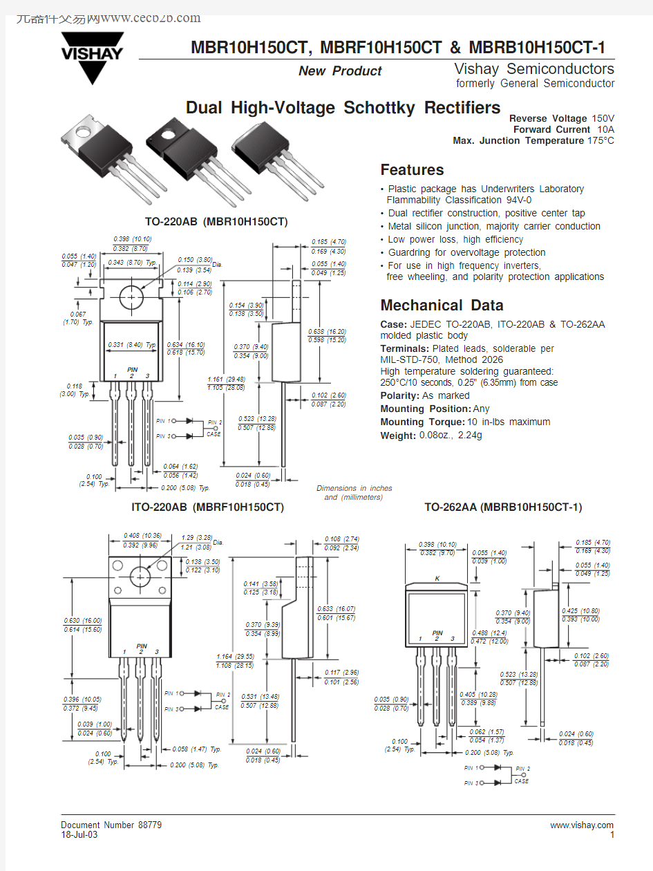
Reverse Voltage 150V Forward Current 10A
Max. Junction Temperature 175°C
PIN 1PIN 3
TO-220AB (MBR10H150CT)
TO-262AA (MBRB10H150CT-1)
Features
? Plastic package has Underwriters Laboratory Flammability Classification 94V-0
? Dual rectifier construction, positive center tap ? Metal silicon junction, majority carrier conduction JEDEC TO-220AB, ITO-220AB & TO-262AA Plated leads, solderable per As marked
Any
10 in-lbs maximum 0.08oz., 2.24g
Document Number https://www.doczj.com/doc/9e15488512.html,
MBR10H150CT , MBRF10H150CT & MBRB10H150CT-1
Vishay Semiconductors
formerly General Semiconductor
Maximum Ratings
(T C = 25°C unless otherwise noted)
Parameter
Symbol MBR10H150CT
Unit Maximum repetitive peak reverse voltage V RRM 150V Working peak reverse voltage V RWM 150V Maximum DC blocking voltage
V DC 150V Maximum average forward rectified current Total device 10(see fig. 1)Per leg I F(AV)5A Peak forward surge current
8.3ms single half sine-wave superimposed I FSM 160A on rated load (JEDEC Method) per leg
Peak repetitive reverse current per leg at t p = 2μs, 1KH Z I RRM 1.0A Peak non-repetitive reverse surge energy per leg E RSM 10mJ (8/20μs waveform)
Non-repetitive avalanche energy per leg at 25°C, I AS = 1.5A, L=10mH E AS 11.25mJ Voltage rate of change (rated V R )
dv/dt 10,000V/μs Operating junction and storage temperature range T J , T STG –65 to +175°C RMS Isolation voltage (MBRF type only) from terminals 4500(1)to heatsink with t = 1 second, RH ≤30%
V ISOL
3500(2)V
1500(3)
Electrical Characteristics (T C = 25°C unless otherwise noted)
Parameter
Symbol Value Unit Maximum instantaneous at I F = 5.0A, T J = 25°C 0.88forward voltage per leg (4)
at I F = 5.0A, T J = 125°C V F
0.72V
at I F = 10A, T J = 25°C 0.96at I F = 10A, T J = 125°C
0.80Maximum reverse current per leg
T J = 25°C 5.0μA at working peak reverse voltage (Note 4)
T J = 125°C
I R
1.0
mA
Thermal Characteristics (T C = 25°C unless otherwise noted)
Parameter
Symbol MBR MBRF MBRB Unit
Typical thermal resistance per leg
R θJC
2.4
4.5
2.4
O
C/W
Notes:
(1) Clip mounting (on case), where lead does not overlap heatsink with 0.110” offset (2) Clip mounting (on case), where leads do overlap heatsink
(3) Screw mounting with 4-40 screw, where washer diameter is ≤ 4.9 mm (0.19”)(4) Pulse test: 300μs pulse width, 1% duty cycle
https://www.doczj.com/doc/9e15488512.html, Document Number 88779
0.10.30.20.40.60.8 1.00.50.7
0.9 1.1 1.2100
10
0.1
1
0.01
1
10
100
10
100
0.1
0.1
1
Fig. 3 – Typical Instantaneous Forward Characteristics Per Leg
J u n c t i o n C a p a c i t a n c e (p F )
1
10
100
100
100010000
0.1
10Fig. 5 – Typical Junction Capacitance
Per Leg
Reverse Voltage (V)
1020305070100
40608090Fig. 4 – Typical Reverse Characteristics Per Leg
Fig. 6 – Typical Transient Thermal Impedance Per Leg
t -- Pulse Duration (sec.)
Instantaneous Forward Voltage (V)Percent of Rated Peak Reverse Voltage (%)
I F -- I n s t a n t a n e o u s F o r w a r d C u r r e n t (A )
T r a n s i e n t T h e r m a l I m p e d a n c e (°C /W )
2468
10
12
255075100125150
175
Fig. 1 – Forward Derating Curve
(Total)
A v e r a g e F o r w a r d C u r r e n t (A )
Case Temperature (°C)020*********
1801601401201001
10
100
Fig. 2 – Maximum Non-Repetitive Peak Forward Surge Current Per Leg
P e a k F o r w a r d S u r g e C u r r e n t (A )
Number of Cycles at 60 H Z
MBR10H150CT , MBRF10H150CT & MBRB10H150CT-1
Vishay Semiconductors
formerly General Semiconductor
Ratings and
Characteristic Curves (T A = 25°C unless otherwise noted)
Document Number https://www.doczj.com/doc/9e15488512.html,