3-电气工程及其自动化专业 外文文献 英文文献 外文翻译 plc方面
- 格式:doc
- 大小:60.00 KB
- 文档页数:11
外文原文:PLC CharacteristicPLC English full title Programmable Logic Controller, Chinese full title as the programmable logical controller, the definition is: One kind of digital operation operation's electronic system, for designs specially in the industry environment application. It uses a kind of programmable memory, uses in its internally stored program, the actuating logic operation, the sequential control, fixed time, counting and arithmetic operation and so on face user's instruction, and through digital either simulation type input/output control each type machinery or production process.PLC characteristic:2.1 reliability is high, antijamming ability. depending on the nature is the electric control equipment's essential performance. Because PLC uses the modern large scale integrated circuit technology, used the strict technique of production manufacture, the internal circuit has adopted the advanced antijamming technology, had the very high reliability. For example the Mitsubishi Corporation produces F series PLC mean time between failure reaches as high as for 300,000 hours. Some use redundancy CPU PLC average trouble-free operating time is longer. From the PLC outside the aircraft electric circuit, uses the PLC constitution control system, compares with the same level scale following the electrical pick-off system, the electrical wiring and the switch contact reduced to several hundreds even several thousands 1, the breakdown also greatly reduces. In addition, PLC has the hardware fault self-measuring ability, presents when the breakdown may send out the warning information promptly. In the application software, the application may also enroll the periphery component's breakdown from the diagnostic program, causes in the system also obtains the breakdown besides the PLC electric circuit and the equipment from the diagnosis protection. Thus, the overall system has the extremely high reliability also not to feel strange.2.2 necessary complete, the function is perfect, serviceable. PLC develops today, had already formed the large, medium and small each scale serialized product. May use in each scale the industrial control situation. Besides the logical processing function, modern PLC mostly has the consummation data operation ability, may use in each kind of numerical control domain. In recent years the PLC function unit emerged massively, causes PLC to seep the position control, the temperature control, CNC and so on each industrial control. In addition the PLC traffic capacity's enhancement and the man-machine contact surface technology's development, usesPLC to compose each kind of control system becomes very easy.2.3 easy to study easily to use, the depth is welcome the engineers and technicians. PLC takes the general industrial control computer, is faces Industrial and mining establishment's labor to control the equipment. Its connection is easy, the programming language accepts easy for the engineers and technicians. The trapezoidal chart language's graphics symbol and the turn of expression and the relay circuit diagram is quite close, only uses PLC the few switch quantity logical control instruction to be possible to realize the relay electric circuit's function conveniently. For not the familiar electronic circuit, did not understand the computer principle and the assembly language person uses the computer to be engaged in the industrial control to open gate of the convenience. the2.4 system's design, the construction work load are small, maintain conveniently, easy to transform. PLC replaces the wiring logic with the stored logic, reduced the control device exterior wiring greatly, causes control system design and the construction cycle is the reduction greatly, simultaneously maintains also becomes easy. Causes the identical equipment possibly to become more importantly after the alter procedure change production process. This very suitable multi-varieties, small batch production situation. the2.5 volume is small, the weight is light, the energy consumption is low.Take subminiature PLC as the example, recently produced the variety base size is smaller than 100mm, the weight is smaller than 150g, the power loss only counts the tile. Because the volume small very easy to load in the machinery, realizes the integration of machinery ideal control device. Since long, PLC is in the industrial automation control domain throughout the main battlefield, has provided the very reliable control application for various automation control device. It can provide safe reliable and the quite perfect solution for the automated control application, suits in the current Industrial enterprise to the automated need. Since the 1980s, as a result of the computer technology and microelectronic technology's rapidly expand, the enormous impetus PLC development, the PLC function which caused strengthened day by day. If PLC may carry on the simulation quantity control, the position control and the PID control and so on, easy to realize the flexible manufacture system. The long-distance correspondence function realizes causes PLC even more powerful. At present, in the advanced countries, PLC has become the industrial control the standard equipment,has covered all Industrial enterprise nearly using the surface. PLC is one kind of solid state electronic installation, it uses the procedure which stores to control machine's movement or the craft working procedure. PLC is uses for to substitute for traditional the black-white control, compares with it, PLC is more outstanding than in the performance the black-white control logic, the reliability is specially high, the design construction cycle is short, the debugging revises, moreover the volume to be small conveniently, the power loss is low, the use maintenance is convenient. Therefore, this article has studied based on the programmable controller (PLC) electric motor synthesis monitoring and protective system's method. Makes the electric motor movement the three-phase asynchronous machine. Because the three-phase asynchronous motor rotor's rotational speed is lower than the rotary field the rotational speed, the rotor winding has the relative motion with the magnetic field, but the induced emf and the electric current, and have the electromagnetism torque with the magnetic field interaction, realizes the energy pares with the single-phase asynchronous motor, the three-phase asynchronous motor performance characteristic is good, and may save each material. The crooked substructure's difference, the three-phase asynchronous motor may divide into the cage type and wind thread the type two kinds. The cage type rotor's asynchronous motor structure is simple, the movement is reliable, the weight is light, the price was cheap, obtained the widespread application, its major object was the velocity modulation difficulty. The regulating rheostat resistance may improve electric motor's starting ability and adjust electric motor's rotational speed. The three-phase asynchronous motor will change the voltage not to change the rotational speed, commonly used changes the number of pole pairs. Changes the three-phase power source's frequency. Change sliding, above two common velocity modulation method. The change number of pole pairs needs to look that the electrical machinery is whether appropriate, if in were diode's electrical machinery cannot change, after another was the change, its output correspondingly will also change, was not the stepless change. The change sliding use scope speaks the dot, only uses, in compares the high efficiency to wind thread on the electrical machinery, the small electrical machinery's rotor does not wind thread, changed the rotor induced emf the frequency to change electric motor's rotational speed. Moreover the simple the means are change into the electric motor the slippery difference electrical machinery, might the stepless speed regulation, because in the velocity modulation process, the electrical machinery rotational speed was invariable, like thisoutput the rotational speed to be possible to move has not affected very lowly to the electrical machinery.中文译文:PLC的特点PLC英文全称Programmable Logic Controller ,中文全称为可编程逻辑控制器,定义是:一种数字运算操作的电子系统,专为在工业环境应用而设计的。
附录外文资料PLC technique discussion and future development Along with the development of the ages, the technique that is nowadays is also gradually perfect, the competition plays more more strong; the operation that list depends the artificial has already can't satisfied with the current manufacturing industry foreground, also can't guarantee the request of the higher quantity and high new the image of the technique business enterprise.The people see in produce practice, automate brought the tremendous convenience and the product quantities for people up of assurance, also eased the personnel's labor strength, reduce the establishment on the personnel. The target control of the hard realization in many complicated production lines, whole and excellent turn, the best decision etc., well-trained operation work, technical personnel or expert, governor but can judge and operate easily, can acquire the satisfied result. The research target of the artificial intelligence makes use of the calculator exactly to carry out, imitate these intelligences behavior, moderating the work through person's brain and calculators, with the mode that person's machine combine, for resolve the very complicated problem to look for the best pathWe come in sight of the control that links after the electric appliances in various situation, that is already the that time generation past, now of after use in the mold a perhaps simple equipments of grass-roots control that the electric appliances can do for the low level only;And the PLC emergence also became the epoch-making topic, adding the vivid software control through a very and stable hardware, making the automation head for the new high tide.The PLC biggest characteristics lie in: The electrical engineering teacher already no longer electric hardware up too many calculationses of cost, as long as order the importation that the button switch or the importation of the sensors order to link the PLC up can solve problem, pass to output to order the conjunction contact machine or control the start equipments of the big power after the electric appliances, but theexportation equipments direct conjunction of the small power can.PLC internal containment have the CPU of the CPU, and take to have an I/ O for expand of exterior to connect a people's address and saving machine three big pieces to constitute, CPU core is from an or many is tired to add the machine to constitute, mathematics that they have the logic operation ability, and can read the procedure save the contents of the machine to drive the homologous saving machine and I/ Os to connect after pass the calculation; The I/ O add inner part is tired the input and output system of the machine and exterior link, and deposit the related data into the procedure saving machine or data saving machine; The saving machine can deposit the data that the I/ O input in the saving machine, and in work adjusting to become tired to add the machine and I/ Os to connect, saving machine separately saving machine RAM of the procedure saving machine ROM and datas, the ROM can can do deposit of the data permanence in the saving machine, but RAM only for the CPU computes the temporary calculation usage of hour of buffer space.The PLC anti- interference is very and excellent, our root need not concern its service life and the work situation bad, these all problems have already no longer become the topic that we fail, but stay to our is a concern to come to internal resources of make use of the PLC to strengthen the control ability of the equipments for us, make our equipments more gentle.PLC language is not we imagine of edit collected materials the language or language of Cs to carry on weaving the distance, but the trapezoid diagram that the adoption is original after the electric appliances to control, make the electrical engineering teacher while weaving to write the procedure very easy comprehended the PLC language, and a lot of non- electricity professional also very quickly know and go deep into to the PLC.Is PLC one of the advantage above and only, this is also one part that the people comprehend more and easily, in a lot of equipmentses, the people have already no longer hoped to see too many control buttons, they damage not only and easily and produce the artificial error easiest, small is not a main error perhaps you can still accept; But lead even is a fatal error greatly is what we can't is tolerant of. Newtechnique always for bringing more safe and convenient operation for us, make we a lot of problems for face on sweep but light, do you understand the HMI? Says the HMI here you basically not clear what it is, also have no interest understanding, change one inside text explains it into the touch to hold or man-machine interface you knew, it combines with the PLC to our larger space.HMI the control not only only is reduced the control press button, increase the vivid of the control, more main of it is can sequence of, and at can the change data input to output the feedback with data, control in the temperature curve of imitate but also can keep the manifestation of view to come out. And can write the function help procedure through a plait to provide the help of various what lies in one's power, the one who make operate reduces the otiose error. Currently the HMI factory is also more and more, the function is also more and more strong, the price is also more and more low, the noodles of the usage are wide more and more. The HMI foreground can say that think ° to be good very.At a lot of situations, the list is is a smooth movement that can't guarantee the equipments by the control of the single machine, but pass the information exchanges of the equipments and equipments to attain the result that we want. For example fore pack and the examination of the empress work preface, we will arrive wrapping information feedback to examine the place, and examine the information of the place to also want the feedback to packing. Pass the information share thus to make both the chain connect, becoming a total body, the match of your that thus make is more close, at each other attain to reflect the result that mutually flick.The PLC correspondence has already come more more body now its value, at the PLC and correspondence between PLCs, can pass the communication of the information and the share of the datas to guarantee that of the equipments moderates mutually, the result that arrive already to repair with each other. Data conversion the adoption RS232 between PLC connect to come to the transmission data, but the RS232 pick up a people and can guarantee 10 meters only of deliver the distance, if in the distance of 1000 meters we can pass the RS485 to carry on the correspondence, the longer distance can pass the MODEL only to carry on deliver.The PLC data transmission is just to be called a form to it in a piece of and continuous address that the data of the inner part delivers the other party, we, the PLC of the other party passes to read data in the watch to carry on the operation. If the data that data in the watch is a to establish generally, that is just the general data transmission, for example today of oil price rise, I want to deliver the price of the oil price to lose the oil ally on board, that is the share of the data; But take data in the watch for an instruction procedure that controls the PLC, that had the difficulty very much, for example you have to control one pedestal robot to press the action work that you imagine, you will draw up for it the form that a procedure combine with the data sends out to pass by.The form that information transport contain single work, the half a work and the difference of a workses .The meaning of the single work also is to say both, a can send out only, but a can receive only, for example a spy he can receive the designation of the superior only, but can't give the superior reply; A work of half is also 2 and can can send out similar to accept the data, but can't send out and accept at the same time, for example when you make a phone call is to can't answer the phone, the other party also; But whole pair works is both can send out and accept the data, and can send out and accept at the same time. Be like the Internet is a typical example.The process that information transport also has synchronous and different step cent: The data line and the clock lines are synchronous when synchronous meaning lie in sending out the data, is also the data signal and the clock signals to be carry on by the CPU to send out at the same time, this needs to all want the specialized clock signal each other to carry on the transmission and connect to send, and is constrained, the characteristics of this kind of method lies in its speed very quick, but correspond work time of take up the CPU and also want to be long oppositely, at the same time the technique difficulty also very big. Its request lies in can'ting have an error margins in a datas deliver, otherwise the whole piece according to compare the occurrence mistake, this on the hardware is a bigger difficulty. Applied more and more extensive in some appropriative equipmentses, be like the appropriative medical treatment equipments, the numerical signal equipments...etc., in compare the one data deliver,its result is very good.And the different step is an application the most extensive, this receive benefit in it of technique difficulty is opposite and want to be small, at the same time not need to prepare the specialized clock signal, its characteristics to lie in, its data is partition, the long-lost send out and accept, be the CPU is too busy of time can grind to a stop sex to work, also reduced the difficulty on the hardware, the data throw to lose at the same time opposite want to be little, we can pass the examination of the data to observe whether the data that we send out has the mistake or not, be like strange accidentally the method, tired addition and eight efficacies method etc., can use to helps whether the data that we examine to send out have or not the mistake occurrence, pass the feedback to carry on the discriminator.A line of transmission of the information contain a string of and combine the cent of: The usual PLC is 8 machines, certainly also having 16 machines. We can be an at the time of sending out the data a send out to the other party, also can be 88 send out the data to the other party, an and 8 differentiationses are also the as that we say to send out the data and combine sends out the data. A speed is more and slowly, but as long as 2 or three lines can solve problem, and can use the telephone line to carry on the long range control. But combine the oscular transmission speed is very quick of, it is a string of oscular of 25600%, occupy the advantage in the short distance, the in view of the fact TTL electricity is even, being limited by the scope of one meter generally, it combine unwell used for the data transmission of the long pull, thus the cost is too expensive.Under a lot of circumstances we are total to like to adopt the string to combine the conversion chip to carry on deliver, under this kind of circumstance not need us to carry on to depositted the machine to establish too and complicatedly, but carry on the data exchanges through the data transmission instruction directly, but is not a very viable way in the correspondence, because the PLC of the other party must has been wait for your data exportation at the time of sending out the data, it can't do other works.When you are reading the book, you hear someone knock on door, you stop tostart up of affair, open the door and combine to continue with the one who knock on door a dialogue, the telephone of this time rang, you signal hint to connect a telephone, after connecting the telephone through, return overdo come together knock on door to have a conversation, after dialogue complete, you continue again to see your book, this kind of circumstance we are called the interruption to it, it has the authority, also having sex of have the initiative, the PLC had such function .Its characteristics lie in us and may meet the urgently abrupt affairs in the operation process of the equipments, we want to stop to start immediately up of work, the whereabouts manages the more important affair, this kind of circumstance is we usually meet of, PLC while carry out urgent mission, total will keep the current appearance first, for example the address of the procedure, CPU of tired add the machine data etc., be like to to stick down which the book that we see is when we open the door the page or simply make a mark, because we treat and would still need to continue immediately after book of see the behind. The CPU always does the affair that should do according to our will, but your mistake of give it an affair, it also would be same to do, this we must notice.The interruption is not only a, sometimes existing jointly with the hour several inside break, break off to have the preferred Class, they will carry out the interruption of the higher Class according to person's request. This kind of breaks off the medium interruption to also became to break off the set. The Class that certainly break off is relevant according to various resources of CPU with internal PLC, also following a heap of capacity size of also relevant fasten.The contents that break off has a lot of kinds, for example the exterior break off, correspondence in of send out and accept the interruption and settle and the clock that count break off, still have the WDT to reset the interruption etc., they enriched the CPU to respond to the category while handle various business. Speak thus perhaps you can't comprehend the internal structure and operation orders of the interruption completely also, we do a very small example to explain.Each equipments always will not forget a button, it also is at we meet the urgent circumstance use of, that is nasty to stop the button. When we meet the Human body trouble and surprised circumstances we as long as press it, the machine stops alloperations immediately, and wait for processing the over surprised empress recover the operation again.Nasty stop the internal I/ O of the internal CPU of the button conjunction PLC to connect up, be to press button an exterior to trigger signal for CPU, the CPU carries on to the I/ O to examine again, being to confirm to have the exterior to trigger the signal, CPU protection the spot breaks off procedure counts the machine turn the homologous exterior I/ O automatically in the procedure to go to also, be exterior interruption procedure processing complete, the procedure counts the machine to return the main procedure to continue to work.Have 1:00 can what to explain is we generally would nasty stop the button of exterior break off to rise to the tallest Class, thus guarantee the safety.When we are work a work piece, giving the PLC a signal, counting PLC inner part the machine add 1 to compute us for a day of workload, a count the machine and can solve problem in brief, certainly they also can keep the data under the condition of dropping the electricity, urging the data not to throw to lose, this is also what we hope earnestly.The PLC still has the function that the high class counts the machine, being us while accept some datas of high speed, the high speed that here say is the data of the in all aspects tiny second class, for example the bar code scanner is scanning the data continuously, calculating high-speed signal of the data processor DSP etc., we will adopt the high class to count the machine to help we carry on count. It at the PLC carries out the procedure once discover that the high class counts the machine to should of interruption, will let go of the work on the hand immediately. The trapezoid diagram procedure that passes by to weave the distance again explains the high class for us to carry out procedure to count machine would automatic performance to should of work, thus rise the Class that the high class counts the machine to high one Class.You heard too many this phrases perhaps:" crash", the meaning that is mostly is a workload of CPU to lead greatly, the internal resources shortage etc. the circumstance can't result in procedure circulate. The PLC also has the similar circumstance, there is a watchdog WDT in the inner part of PLC, we can establishtime that a procedure of WDT circulate, being to appear the procedure to jump to turn the mistake in the procedure movement process or the procedure is busy, movement time of the procedure exceeds WDT constitution time, the CPU turn but the WDT reset the appearance. The procedure restarts the movement, but will not carry on the breakage to the interruption.The PLC development has already entered for network ages of correspondence from the mode of the one, and together other works control the net plank and I/ O card planks to carry on the share easily. A state software can pass all se hardwares link, more animation picture of keep the view to carries on the control, and cans pass the Internet to carry on the control in the foreign land, the blast-off that is like the absolute being boat No.5 is to adopt this kind of way to make airship go up the sky.The development of the higher layer needs our continuous effort to obtain.The PLC emergence has already affected a few persons fully, we also obtained more knowledge and precepts from the top one experience of the generation, coming to the continuous development PLC technique, push it toward higher wave tide.摘自《可编程控制器技术讨论与未来发展》中文翻译可编程控制器技术讨论与未来发展随着时代的发展,当今的技术也日趋完善、竞争愈演愈烈;单靠人工的操作已不能满足于目前的制造业前景,也无法保证更高质量的要求和高新技术企业的形象.人们在生产实践中看到,自动化给人们带来了极大的便利和产品质量上的保证,同时也减轻了人员的劳动强度,减少了人员上的编制.在许多复杂的生产过程中难以实现的目标控制、整体优化、最佳决策等,熟练的操作工、技术人员或专家、管理者却能够容易判断和操作,可以获得满意的效果.人工智能的研究目标正是利用计算机来实现、模拟这些智能行为,通过人脑与计算机协调工作,以人机结合的模式,为解决十分复杂的问题寻找最佳的途径我们在各种场合看到了继电器连接的控制,那已经是时代的过去,如今的继电器只能作为低端的基层控制模块或者简单的设备中使用到;而PLC的出现也成为了划时代的主题,通过极其稳定的硬件穿插灵活的软件控制,使得自动化走向了新的高潮。
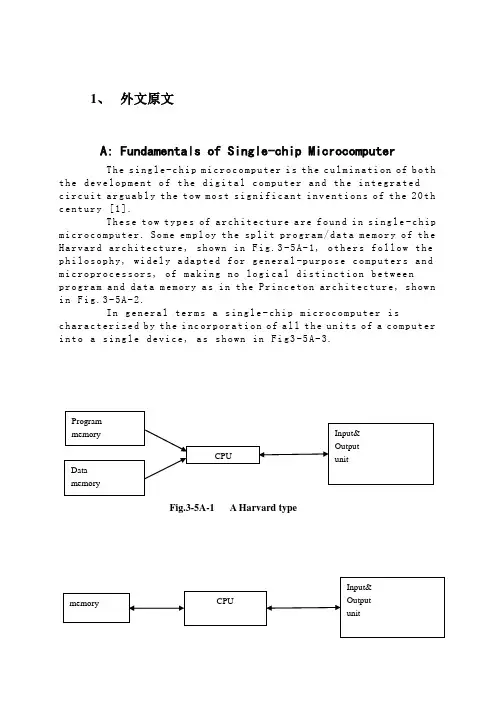
1、外文原文A: Fundamentals of Single-chip MicrocomputerTh e si ng le-c hi p m ic ro co mp ut er i s t he c ul mi na ti on of b oth t h e de ve lo pm en t o f t he d ig it al co m pu te r an d th e i n te gr at edc i rc ui t a rg ua bl y t h e to w m os t s ig ni f ic an t i nv en ti on s o f t he20th c e nt ur y [1].Th es e t ow ty pe s of ar ch it ec tu re a re fo un d i n s in g le-c hip m i cr oc om pu te r. So m e em pl oy t he spl i t pr og ra m/da ta m e mo ry o f th e H a rv ar d ar ch it ect u re, sh ow n in Fi g.3-5A-1, o th ers fo ll ow t he p h il os op hy, wi del y a da pt ed f or ge n er al-p ur po se co m pu te rs a nd m i cr op ro ce ss o r s, o f ma ki ng n o log i ca l di st in ct ion be tw ee np r og ra m an d d at a m e mo ry a s i n t he P r in ce to n ar ch ite c tu re, sh ow n i n F ig.3-5A-2.In g en er al te r ms a s in gl e-chi p m ic ro co mp ut er i sc h ar ac te ri zed b y t he i nc or po ra ti on of a ll t he un it s of a co mp ut er i n to a s in gl e d ev i ce, as s ho wn in Fi g3-5A-3.Fig.3-5A-1 A Harvard typeFig.3-5A-2. A conventional Princeton computerFig3-5A-3. Principal features of a microcomputerRead only memory (ROM).R OM i s us ua ll y f or th e p e rm an en t,n o n-vo la ti le s tor a ge o f an a pp lic a ti on s pr og ra m .M an ym i cr oc om pu te rs an d m ar e in te nd e d f or hi gh-v ol um e a p pl ic at io ns a n d he nc e t h e eco n om ic al m an uf act u re o f th e de vic e s re qu ir es t h at t he co nt en t s o f t he pr og ra m me m or y b e co mm it t ed pe rm a ne nt ly d u ri ng t he m an ufa c tu re o f ch ip s .Cl ea rl y, t hi s i m pl ie s ar i go ro us a pp ro ach to R OM c od e de ve l op me nt s in ce ch a ng es c an no t b e m ad e af te r m anu f a c tu re .Th is d ev e lo pm en t pr oc ess ma y in vo lv e e m ul at io n us in g a so ph is ti ca te d d e ve lo pm en t sy ste m w it h ah a rd wa re e mu la tio n c ap ab il it y as w el l as t he u se o f po we rf ul s o ft wa re t oo ls.So me m an uf act u re rs p ro vi de ad d it io na l RO M opt i on s byi n cl ud in g i n th eir r a n ge d ev ic es wi t h (or i nt en de d f o r u se w it h) u s er p ro gr am ma ble me mo ry. Th e sim p le st o f th es e i s u su al lyd e vi ce w hi ch c an o p er at e in a mi cro p ro ce ss or m od e b y u si ng s om e o f t he i np ut/o utp u t li ne s as a n a d dr es s an d da ta b us f ora c ce ss in g ex te rna l m em or y. T hi s t y pe o f de vi ce ca nb eh av ef u nc ti on al ly a s t h e si ng le ch ip mi cr oc om pu te r fro m w hi ch it is d e ri ve d al be it wi t h re st ri ct ed I/O a nd a m od if ied ex te rn alc i rc ui t. Th e u se o f th es ed ev ic es i s c om mo ne ve n i n pr od uc ti on c i rc ui ts wh er e t he vo lu me do es no t j us tif y t h e d ev el o pm en t c os ts o f c us to m o n-ch i p R OM[2];t he re c a n s ti ll be a s ig nif i ca nt sa vi ng i n I/O an d o th er c h ip s c om pa re d t o a co nv en ti on al mi c ro pr oc es so r b a se d ci rc ui t. Mo r e ex ac t re pl ace m en t fo r RO M dev i ce s ca n be o b ta in ed i n th e f o rm o f va ri an ts w it h 'p ig gy-b ack'E P RO M(Er as ab le pr o gr am ma bl e RO M )s oc ke ts o r d ev ic e s wi th EP RO M i n st ea d o f RO M 。
电气工程及其自动化专业英语作文范文Electrical Engineering and Automation: An Integral Part of Modern SocietyIntroductionElectrical Engineering and Automation, a discipline that has evolved significantly over the past few decades, has become an integral part of modern society. Its widespread applications in industry, agriculture, national defense, and various other fields have propelled it to a pivotal position in the global economy.Historical PerspectiveThe field of Electrical Engineering and Automation was first established approximately forty years ago. As a relatively new discipline, it has quickly grown to encompass a wide range of subfields and applications. From the design of switches for aerospace aircraft to the development of complex automated systems, its influence is pervasive.Core ComponentsThe core of Electrical Engineering and Automation lies in its ability to integrate electricity, machines, and intelligent systems to automate various tasks. This integration enables efficiency, precision, and safety in a wide range of applications.•Electricity and Machines: Electricity provides the power that drives machines and systems. Understanding the behavior ofelectrical circuits, voltage sources, current sources, andvarious network elements is crucial for the effective designand operation of automated systems.•Automation: Automation refers to the use of technology to control and monitor processes and machines with minimal humanintervention. It relies on sensors, actuators, and intelligentcontrollers to achieve desired outcomes.Challenges and OpportunitiesWhile Electrical Engineering and Automation offers immense opportunities for growth and development, it also poses significantchallenges. The complexity of modern systems requires a high level of technical knowledge and expertise. Additionally, the rapid pace of technological advancement requires constant updating of skills and knowledge.However, these challenges also present opportunities for innovation and growth. As new technologies emerge, there is a need for engineers and technicians who can understand and apply them effectively. This creates opportunities for those with a passion for learning and a willingness to adapt to new challenges.ConclusionIn conclusion, Electrical Engineering and Automation is a dynamic and exciting field that offers immense opportunities for growth and development. Its applications are pervasive, and its influence on society is profound. As we continue to push the boundaries of technology, Electrical Engineering and Automation will play an increasingly important role in shaping our future.。
电气工程与自动化毕业论文中英文资料外文翻译The Transformer on load ﹠Introduction to DC MachinesIt has been shown that a primary input voltage 1V can be transformed to any desired open-circuit secondary voltage 2E by a suitable choice of turns ratio. 2E is available for circulating a load current impedance. For the moment, a lagging power factor will be considered. The secondary current and the resulting ampere-turns 22N I will change the flux, tending to demagnetize the core, reduce m Φ and with it 1E . Because the primary leakage impedance drop is so low, a small alteration to 1Ewill cause an appreciable increase of primary current from 0I to a new value of 1Iequal to ()()i jX R E V ++111/. The extra primary current and ampere-turns nearly cancel the whole of the secondary ampere-turns. This being so , the mutual flux suffers only a slight modification and requires practically the same net ampere-turns 10N I as on no load. The total primary ampere-turns are increased by an amount 22N I necessary to neutralize the same amount of secondary ampere-turns. In thevector equation , 102211N I N I N I =+; alternatively, 221011N I N I N I -=. At full load,the current 0I is only about 5% of the full-load current and so 1I is nearly equalto 122/N N I . Because in mind that 2121/N N E E =, the input kV A which is approximately 11I E is also approximately equal to the output kV A, 22I E .The physical current has increased, and with in the primary leakage flux towhich it is proportional. The total flux linking the primary ,111Φ=Φ+Φ=Φm p , isshown unchanged because the total back e.m.f.,(dt d N E /111Φ-)is still equal and opposite to 1V . However, there has been a redistribution of flux and the mutual component has fallen due to the increase of 1Φ with 1I . Although the change is small, the secondary demand could not be met without a mutual flux and e.m.f.alteration to permit primary current to change. The net flux s Φlinking thesecondary winding has been further reduced by the establishment of secondaryleakage flux due to 2I , and this opposes m Φ. Although m Φ and 2Φ are indicatedseparately , they combine to one resultant in the core which will be downwards at theinstant shown. Thus the secondary terminal voltage is reduced to dt d N V S /22Φ-=which can be considered in two components, i.e. dt d N dt d N V m //2222Φ-Φ-=orvectorially 2222I jX E V -=. As for the primary, 2Φ is responsible for a substantiallyconstant secondary leakage inductance222222/Λ=ΦN i N . It will be noticed that the primary leakage flux is responsible for part of the change in the secondary terminal voltage due to its effects on the mutual flux. The two leakage fluxes are closely related; 2Φ, for example, by its demagnetizing action on m Φ has caused the changes on the primary side which led to the establishment of primary leakage flux.If a low enough leading power factor is considered, the total secondary flux and the mutual flux are increased causing the secondary terminal voltage to rise with load. p Φ is unchanged in magnitude from the no load condition since, neglecting resistance, it still has to provide a total back e.m.f. equal to 1V . It is virtually the same as 11Φ, though now produced by the combined effect of primary and secondary ampere-turns. The mutual flux must still change with load to give a change of 1E and permit more primary current to flow. 1E has increased this time but due to the vector combination with 1V there is still an increase of primary current.Two more points should be made about the figures. Firstly, a unity turns ratio has been assumed for convenience so that '21E E =. Secondly, the physical picture is drawn for a different instant of time from the vector diagrams which show 0=Φm , if the horizontal axis is taken as usual, to be the zero time reference. There are instants in the cycle when primary leakage flux is zero, when the secondary leakage flux is zero, and when primary and secondary leakage flux is zero, and when primary and secondary leakage fluxes are in the same sense.The equivalent circuit already derived for the transformer with the secondary terminals open, can easily be extended to cover the loaded secondary by the addition of the secondary resistance and leakage reactance.Practically all transformers have a turns ratio different from unity although such an arrangement is sometimes employed for the purposes of electrically isolating one circuit from another operating at the same voltage. To explain the case where 21N N ≠ the reaction of the secondary will be viewed from the primary winding. The reaction is experienced only in terms of the magnetizing force due to the secondary ampere-turns. There is no way of detecting from the primary side whether 2I is large and 2N small or vice versa, it is the product of current and turns which causesthe reaction. Consequently, a secondary winding can be replaced by any number of different equivalent windings and load circuits which will give rise to an identical reaction on the primary .It is clearly convenient to change the secondary winding to an equivalent winding having the same number of turns 1N as the primary.With 2N changes to 1N , since the e.m.f.s are proportional to turns, 2212)/('E N N E = which is the same as 1E .For current, since the reaction ampere turns must be unchanged 1222'''N I N I = must be equal to 22N I .i.e. 2122)/(I N N I =.For impedance , since any secondary voltage V becomes V N N )/(21, and secondary current I becomes I N N )/(12, then any secondary impedance, including load impedance, must becomeI V N N I V /)/('/'221=. Consequently,22212)/('R N N R = and 22212)/('X N N X = . If the primary turns are taken as reference turns, the process is called referring to the primary side.There are a few checks which can be made to see if the procedure outlined is valid.For example, the copper loss in the referred secondary winding must be the same as in the original secondary otherwise the primary would have to supply a differentloss power. ''222R I must be equal to 222R I . )222122122/()/(N N R N N I •• does infact reduce to 222R I .Similarly the stored magnetic energy in the leakage field)2/1(2LI which is proportional to 22'X I will be found to check as ''22X I . The referred secondary 2212221222)/()/(''I E N N I N N E I E kVA =•==.The argument is sound, though at first it may have seemed suspect. In fact, if the actual secondary winding was removed physically from the core and replaced by the equivalent winding and load circuit designed to give the parameters 1N ,'2R ,'2X and '2I , measurements from the primary terminals would be unable to detect any difference in secondary ampere-turns, kVA demand or copper loss, under normal power frequency operation.There is no point in choosing any basis other than equal turns on primary andreferred secondary, but it is sometimes convenient to refer the primary to the secondary winding. In this case, if all the subscript 1’s are interchanged for the subscript 2’s, the necessary referring constants are easily found; e.g. 2'1R R ≈,21'X X ≈; similarly 1'2R R ≈ and 12'X X ≈.The equivalent circuit for the general case where 21N N ≠ except that m r hasbeen added to allow for iron loss and an ideal lossless transformation has been included before the secondary terminals to return '2V to 2V .All calculations of internal voltage and power losses are made before this ideal transformation is applied. The behaviour of a transformer as detected at both sets of terminals is the same as the behaviour detected at the corresponding terminals of this circuit when the appropriate parameters are inserted. The slightly different representation showing the coils 1N and 2N side by side with a core in between is only used for convenience. On the transformer itself, the coils are , of course , wound round the same core.Very little error is introduced if the magnetising branch is transferred to the primary terminals, but a few anomalies will arise. For example ,the current shown flowing through the primary impedance is no longer the whole of the primary current.The error is quite small since 0I is usually such a small fraction of 1I . Slightlydifferent answers may be obtained to a particular problem depending on whether or not allowance is made for this error. With this simplified circuit, the primary and referred secondary impedances can be added to give:221211)/(Re N N R R += and 221211)/(N N X X Xe +=It should be pointed out that the equivalent circuit as derived here is only valid for normal operation at power frequencies; capacitance effects must be taken into account whenever the rate of change of voltage would give rise to appreciablecapacitance currents, dt CdV I c /=. They are important at high voltages and atfrequencies much beyond 100 cycles/sec. A further point is not the only possible equivalent circuit even for power frequencies .An alternative , treating the transformer as a three-or four-terminal network, gives rise to a representation which is just as accurate and has some advantages for the circuit engineer who treats all devices as circuit elements with certain transfer properties. The circuit on this basiswould have a turns ratio having a phase shift as well as a magnitude change, and the impedances would not be the same as those of the windings. The circuit would not explain the phenomena within the device like the effects of saturation, so for an understanding of internal behaviour .There are two ways of looking at the equivalent circuit:(a) viewed from the primary as a sink but the referred load impedance connected across '2V ,or(b) viewed from the secondary as a source of constant voltage 1V with internal drops due to 1Re and 1Xe . The magnetizing branch is sometimes omitted in this representation and so the circuit reduces to a generator producing a constant voltage 1E (actually equal to 1V ) and having an internal impedance jX R + (actually equal to 11Re jXe +).In either case, the parameters could be referred to the secondary winding and this may save calculation time .The resistances and reactances can be obtained from two simple light load tests. Introduction to DC MachinesDC machines are characterized by their versatility. By means of various combination of shunt, series, and separately excited field windings they can be designed to display a wide variety of volt-ampere or speed-torque characteristics for both dynamic and steadystate operation. Because of the ease with which they can be controlled , systems of DC machines are often used in applications requiring a wide range of motor speeds or precise control of motor output.The essential features of a DC machine are shown schematically. The stator has salient poles and is excited by one or more field coils. The air-gap flux distribution created by the field winding is symmetrical about the centerline of the field poles. This axis is called the field axis or direct axis.As we know , the AC voltage generated in each rotating armature coil is converted to DC in the external armature terminals by means of a rotating commutator and stationary brushes to which the armature leads are connected. The commutator-brush combination forms a mechanical rectifier, resulting in a DCarmature voltage as well as an armature m.m.f. wave which is fixed in space. The brushes are located so that commutation occurs when the coil sides are in the neutral zone , midway between the field poles. The axis of the armature m.m.f. wave then in 90 electrical degrees from the axis of the field poles, i.e., in the quadrature axis. In the schematic representation the brushes are shown in quarature axis because this is the position of the coils to which they are connected. The armature m.m.f. wave then is along the brush axis as shown.. (The geometrical position of the brushes in an actual machine is approximately 90 electrical degrees from their position in the schematic diagram because of the shape of the end connections to the commutator.)The magnetic torque and the speed voltage appearing at the brushes are independent of the spatial waveform of the flux distribution; for convenience we shall continue to assume a sinusoidal flux-density wave in the air gap. The torque can then be found from the magnetic field viewpoint.The torque can be expressed in terms of the interaction of the direct-axis air-gapflux per pole d Φ and the space-fundamental component 1a F of the armature m.m.f.wave . With the brushes in the quadrature axis, the angle between these fields is 90 electrical degrees, and its sine equals unity. For a P pole machine 12)2(2a d F P T ϕπ=In which the minus sign has been dropped because the positive direction of thetorque can be determined from physical reasoning. The space fundamental 1a F ofthe sawtooth armature m.m.f. wave is 8/2π times its peak. Substitution in above equation then givesa d a a d a i K i m PC T ϕϕπ==2 Where a i =current in external armature circuit;a C =total number of conductors in armature winding;m =number of parallel paths through winding;Andm PC K aa π2=Is a constant fixed by the design of the winding.The rectified voltage generated in the armature has already been discussedbefore for an elementary single-coil armature. The effect of distributing the winding in several slots is shown in figure ,in which each of the rectified sine waves is the voltage generated in one of the coils, commutation taking place at the moment when the coil sides are in the neutral zone. The generated voltage as observed from the brushes is the sum of the rectified voltages of all the coils in series between brushesand is shown by the rippling line labeled a e in figure. With a dozen or socommutator segments per pole, the ripple becomes very small and the average generated voltage observed from the brushes equals the sum of the average values ofthe rectified coil voltages. The rectified voltage a e between brushes, known also asthe speed voltage, ism d a m d a a W K W m PC e ϕϕπ==2 Where a K is the design constant. The rectified voltage of a distributed winding has the same average value as that of a concentrated coil. The difference is that the ripple is greatly reduced.From the above equations, with all variable expressed in SI units:m a a Tw i e =This equation simply says that the instantaneous electric power associated with the speed voltage equals the instantaneous mechanical power associated with the magnetic torque , the direction of power flow being determined by whether the machine is acting as a motor or generator.The direct-axis air-gap flux is produced by the combined m.m.f. f f i N ∑ of the field windings, the flux-m.m.f. characteristic being the magnetization curve for the particular iron geometry of the machine. In the magnetization curve, it is assumed that the armature m.m.f. wave is perpendicular to the field axis. It will be necessary to reexamine this assumption later in this chapter, where the effects of saturation are investigated more thoroughly. Because the armature e.m.f. is proportional to flux times speed, it is usually more convenient to express the magnetization curve in termsof the armature e.m.f. 0a e at a constant speed 0m w . The voltage a e for a given fluxat any other speed m w is proportional to the speed,i.e. 00a m m a e w w e =Figure shows the magnetization curve with only one field winding excited. This curve can easily be obtained by test methods, no knowledge of any design details being required.Over a fairly wide range of excitation the reluctance of the iron is negligible compared with that of the air gap. In this region the flux is linearly proportional to the total m.m.f. of the field windings, the constant of proportionality being the direct-axis air-gap permeance.The outstanding advantages of DC machines arise from the wide variety of operating characteristics which can be obtained by selection of the method of excitation of the field windings. The field windings may be separately excited from an external DC source, or they may be self-excited; i.e., the machine may supply its own excitation. The method of excitation profoundly influences not only the steady-state characteristics, but also the dynamic behavior of the machine in control systems.The connection diagram of a separately excited generator is given. The required field current is a very small fraction of the rated armature current. A small amount of power in the field circuit may control a relatively large amount of power in the armature circuit; i.e., the generator is a power amplifier. Separately excited generators are often used in feedback control systems when control of the armature voltage over a wide range is required. The field windings of self-excited generators may be supplied in three different ways. The field may be connected in series with the armature, resulting in a shunt generator, or the field may be in two sections, one of which is connected in series and the other in shunt with the armature, resulting in a compound generator. With self-excited generators residual magnetism must be present in the machine iron to get the self-excitation process started.In the typical steady-state volt-ampere characteristics, constant-speed primemovers being assumed. The relation between the steady-state generated e.m.f. a Eand the terminal voltage t V isa a a t R I E V -=Where a I is the armature current output and a R is the armature circuitresistance. In a generator, a E is large than t V ; and the electromagnetic torque T is acountertorque opposing rotation.The terminal voltage of a separately excited generator decreases slightly with increase in the load current, principally because of the voltage drop in the armature resistance. The field current of a series generator is the same as the load current, so that the air-gap flux and hence the voltage vary widely with load. As a consequence, series generators are not often used. The voltage of shunt generators drops off somewhat with load. Compound generators are normally connected so that the m.m.f. of the series winding aids that of the shunt winding. The advantage is that through the action of the series winding the flux per pole can increase with load, resulting in a voltage output which is nearly constant. Usually, shunt winding contains many turns of comparatively heavy conductor because it must carry the full armature current of the machine. The voltage of both shunt and compound generators can be controlled over reasonable limits by means of rheostats in the shunt field. Any of the methods of excitation used for generators can also be used for motors. In the typical steady-state speed-torque characteristics, it is assumed that the motor terminals are supplied froma constant-voltage source. In a motor the relation between the e.m.f. a E generated inthe armature and the terminal voltage t V isa a a t R I E V +=Where a I is now the armature current input. The generated e.m.f. a E is nowsmaller than the terminal voltage t V , the armature current is in the oppositedirection to that in a motor, and the electromagnetic torque is in the direction to sustain rotation of the armature.In shunt and separately excited motors the field flux is nearly constant. Consequently, increased torque must be accompanied by a very nearly proportional increase in armature current and hence by a small decrease in counter e.m.f. to allow this increased current through the small armature resistance. Since counter e.m.f. is determined by flux and speed, the speed must drop slightly. Like the squirrel-cage induction motor ,the shunt motor is substantially a constant-speed motor having about 5 percent drop in speed from no load to full load. Starting torque and maximum torque are limited by the armature current that can be commutatedsuccessfully.An outstanding advantage of the shunt motor is ease of speed control. With a rheostat in the shunt-field circuit, the field current and flux per pole can be varied at will, and variation of flux causes the inverse variation of speed to maintain counter e.m.f. approximately equal to the impressed terminal voltage. A maximum speed range of about 4 or 5 to 1 can be obtained by this method, the limitation again being commutating conditions. By variation of the impressed armature voltage, very wide speed ranges can be obtained.In the series motor, increase in load is accompanied by increase in the armature current and m.m.f. and the stator field flux (provided the iron is not completely saturated). Because flux increases with load, speed must drop in order to maintain the balance between impressed voltage and counter e.m.f.; moreover, the increase in armature current caused by increased torque is smaller than in the shunt motor because of the increased flux. The series motor is therefore a varying-speed motor with a markedly drooping speed-load characteristic. For applications requiring heavy torque overloads, this characteristic is particularly advantageous because the corresponding power overloads are held to more reasonable values by the associated speed drops. Very favorable starting characteristics also result from the increase in flux with increased armature current.In the compound motor the series field may be connected either cumulatively, so that its.m.m.f.adds to that of the shunt field, or differentially, so that it opposes. The differential connection is very rarely used. A cumulatively compounded motor has speed-load characteristic intermediate between those of a shunt and a series motor, the drop of speed with load depending on the relative number of ampere-turns in the shunt and series fields. It does not have the disadvantage of very high light-load speed associated with a series motor, but it retains to a considerable degree the advantages of series excitation.The application advantages of DC machines lie in the variety of performance characteristics offered by the possibilities of shunt, series, and compound excitation. Some of these characteristics have been touched upon briefly in this article. Stillgreater possibilities exist if additional sets of brushes are added so that other voltages can be obtained from the commutator. Thus the versatility of DC machine systems and their adaptability to control, both manual and automatic, are their outstanding features.中文翻译负载运行的变压器及直流电机导论通过选择合适的匝数比,一次侧输入电压1V 可任意转换成所希望的二次侧开路电压2E 。
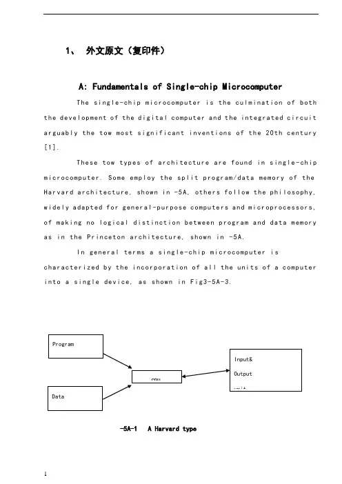
1、外文原文(复印件)A: Fundamentals of Single-chip MicrocomputerTh e si ng le-ch i p mi cr oc om pu ter is t he c ul mi nat i on o f bo th t h e d ev el op me nt o f th e d ig it al com p ut er an d t he int e gr at ed ci rc ui ta r gu ab ly th e t ow m os t s i gn if ic ant i nv en ti on s o f t h e 20t h c en tu ry[1].Th es e to w typ e s of a rc hi te ctu r e ar e fo un d i n s in gl e-ch ip m i cr oc om pu te r. So m e em pl oy t he sp l it p ro gr am/d ata me mo ry o f th e H a rv ar d ar ch it ect u re, sh ow n i n -5A, ot he rs fo ll ow th e ph i lo so ph y, w i de ly a da pt ed fo r g en er al-p ur pos e c om pu te rs an d m i cr op ro ce ss or s, o f m a ki ng no lo gi c al di st in ct io n b e tw ee n p ro gr am a n d da t a m em ory a s i n th e Pr in cet o n ar ch it ec tu re,sh ow n in-5A.In g en er al te r ms a s in gl e-chi p m ic ro co mp ut er i sc h ar ac te ri zed b y the i nc or po ra tio n of al l t he uni t s o f a co mp ut er i n to a s in gl e dev i ce, as s ho wn in Fi g3-5A-3.-5A-1 A Harvard type-5A. A conventional Princeton computerFig3-5A-3. Principal features of a microcomputerRead only memory (ROM).R OM i s u su al ly f or th e p er ma ne nt, n o n-vo la ti le s tor a ge o f an a pp lic a ti on s pr og ra m .M an ym i cr oc om pu te rs an d mi cr oc on tr ol le r s a re in t en de d fo r h ig h-v ol ume a p pl ic at io ns a nd h en ce t he e co nom i ca l ma nu fa ct ure of t he d ev ic es r e qu ir es t ha t the co nt en ts o f the pr og ra m me mo ry b e co mm it te dp e rm an en tl y d ur in g th e m an uf ac tu re o f c hi ps . Cl ear l y, th is im pl ie sa ri g or ou s a pp roa c h t o R OM co de d e ve lo pm en t s in ce c ha ng es ca nn otb e m ad e af te r man u fa ct ur e .T hi s d e ve lo pm en t pr oce s s ma y in vo lv e e m ul at io n us in g a s op hi st ic at ed deve lo pm en t sy st em w i th a ha rd wa re e m ul at io n ca pa bil i ty a s we ll a s th e u se of po we rf ul so ft wa re t oo ls.So me m an uf act u re rs p ro vi de ad d it io na l RO M opt i on s byi n cl ud in g i n th ei r ra ng e de vi ce s wi th (or i nt en de d fo r us e wi th) u s er pr og ra mm ab le m em or y. Th e s im p le st of th es e i s us ua ll y d ev ice w h ic h ca n op er ate in a m ic ro pr oce s so r mo de b y usi n g so me o f th e i n pu t/ou tp ut li ne s as a n ad dr es s an d da ta b us f or acc e ss in g e xt er na l m e mo ry. T hi s t ype o f d ev ic e c an b e ha ve fu nc ti on al l y a s t he si ng le c h ip mi cr oc om pu te r fr om wh ic h i t i s de ri ve d a lb eit w it h r es tr ic ted I/O an d a mo di fie d e xt er na l ci rcu i t. T he u se o f t h es e RO Ml es sd e vi ce s is c om mo n e ve n in p ro du ct io n c ir cu it s wh er e t he v ol um e do es n o t ju st if y th e d e ve lo pm en t co sts of c us to m on-ch i p RO M[2];t he re c a n st il l b e a si g ni fi ca nt s a vi ng in I/O a nd ot he r c hi ps co mp ar ed t o a c on ve nt io nal mi cr op ro ce ss or b as ed c ir cu it. M o re e xa ctr e pl ac em en t fo r RO M d ev ic es c an b e o bt ai ne d in t he f o rm o f va ri an ts w i th 'pi gg y-ba ck'EP RO M(Er as ab le p ro gr am ma bl e ROM)s oc ke ts o rd e vi ce s w it h EP ROM i ns te ad o f R OM 。
自动化专业本科毕业设计英文翻译学院(部):专业班级:学生姓名:指导教师:年月日Programmable Logic ControllerONE:PLC overviewProgrammable controller is the first in the late 1960s in the United States, then called PLC programmable logic controller (Programmable Logic Controller) is used to replace relays. For the implementation of the logical judgment, timing, sequence number, and other control functions. The concept is presented PLC General Motors Corporation. PLC and the basic design is the computer functional improvements, flexible, generic and other advantages and relay control system simple and easy to operate, such as the advantages of cheap prices combined controller hardware is standard and overall. According to the practical application of target software in order to control the content of the user procedures memory controller, the controller and connecting the accused convenient target.In the mid-1970s, the PLC has been widely used as a central processing unit microprocessor, import export module and the external circuits are used, large-scale integrated circuits even when the Plc is no longer the only logical (IC) judgment functions also have data processing, PID conditioning and data communications functions. International Electro technical Commission (IEC) standards promulgated programmable controller for programmable controller draft made the following definition : programmable controller is a digital electronic computers operating system, specifically for applications in the industrial design environment. It used programmable memory, used to implement logic in their internal storage operations, sequence control, timing, counting and arithmetic operations, such as operating instructions, and through digital and analog input and output, the control of various types of machinery or production processes. Programmable controller and related peripherals, and industrial control systems easily linked to form a whole, to expand its functional design. Programmable controller for the user, is a non-contact equipment, the procedures can be changed to change production processes. The programmable controller has become a powerful tool for factory automation, widely popular replication.Programmable controller is user-oriented industries dedicated control computer, with many distinctive features.First, high reliability, anti-interference capability;Second,programming visual, simple;Third, adaptability good;Fourth functional improvements, strong functional interface. TWO:History of PLCProgrammable Logic Controllers (PLC), a computing device invented by Richard E. Morley in 1968, have been widely used in industry including manufacturing systems, transportation systems, chemical process facilities, and many others. At that time, the PLC replaced the hardwired logic with soft-wired logic or so-called relay ladder logic (RLL), a programming language visually resembling the hardwired logic, and reduced thereby the configuration time from 6 months down to 6 days [Moody and Morley, 1999].Although PC based control has started to come into place, PLC based control will remain the technique to which the majority of industrial applications will adhere due to its higher performance, lower price, and superior reliability in harsh environments. Moreover, according to a study on the PLC market of Frost and Sullivan [1995], an increase of the annual sales volume to 15 million PLC per year with the hardware value of more than 8 billion US dollars has been predicted, though the prices of computing hardware is steadily dropping. The inventor of the PLC, Richard E Morley, fairly considers the PLC market as a 5-billion industry at the present time.Though PLCs are widely used in industrial practice, the programming of PLC based control systems is still very much relying on trial-and-error. Alike software engineering, PLC software design is facing the software dilemma or crisis in a similar way. Morley himself emphasized this aspect most forcefully by indicatingIf houses were built like software projects, a single woodpecker could d estroy civilization.”Particularly, practical problems in PLC programming are to eliminate software bugs and to reduce the maintenance costs of old ladderlogic programs. Though the hardware costs of PLC are dropping continuously, reducing the scan time of the ladder logic is still an issue in industry so that low-cost PLC can be used.In general, the productivity in generating PLC is far behind compared to other domains, for instance, VLSI design, where efficient computer aided design tools are in practice. Existent software engineering methodologies are not necessarily applicable to the PLC based software design because PLC-programming requires a simultaneous consideration of hardware and software. The software design becomes, thereby, more and more the major cost driver. In many industrial design projects, more than of the manpower allocated for the control system design and installation is scheduled for testing and debugging PLC programs.In addition, current PLC based control systems are not properly designed to support the growing demand for flexibility and reconfigurability of manufacturing systems. A further problem, impelling the need for a systematic design methodology, is the increasing software complexity in large-scale projects.The objective of this thesis is to develop a systematic software design methodology for PLC operated automation systems. The design methodology involves high-level description based on state transition models that treat automation control systems as discrete event systems, a stepwise design process, and set of design rules providing guidance and measurements to achieve a successful design. The tangible outcome of this research is to find a way to reduce the uncertainty in managing the control software development process, that is, reducing programming and debugging time and their variation, increasing flexibility of the automation systems, and enabling software reusability through modularity. The goal is to overcome shortcomings of current programming strategies that are based on the experience of the individual software developer. Three:now of PLCFrom the structure is divided into fixed PLC and Module PLC, the two kinds of PLC including CPU board, I/O board, display panel, memory block, power, these elements into a do not remove overall. Module type PLC including CPU module, I/O modules, memory, thepower modules, bottom or a frame, these modules can be according to certain rules combination configuration.In the user view, a detailed analysis of the CPU's internal unnecessary, but working mechanism of every part of the circuit. The CPU control works, by it reads CPU instruction, interprets the instruction and executes instructions. But the pace of work by shock signal control.Unit work under the controller command used in a digital or logic operations.In computing and storage register of computation result, it is also among the controller command and work. CPU speed and memory capacity is the important parameters fot PLC . its determines the PLC speed of work, IO PLC number and software capacity, so limits to control size.Central Processing Unit (CPU) is the brain of a PLC controller. CPU itself is usually one of the microcontrollers. Aforetime these were 8-bit microcontrollers such as 8051, and now these are 16-and 32-bit microcontrollers. Unspoken rule is that you’ll find mostly Hitachi and Fujicu microcontrollers in PLC controllers by Japanese makers, Siemens in European controllers, and Motorola microcontrollers in American ones. CPU also takes care of communication, interconnectedness among other parts of PLC controllers, program execution, memory operation, overseeing input and setting up of an output.System memory (today mostly implemented in FLASH technology) is used by a PLC for a process control system. Aside form. this operating system it also contains a user program translated foram ladder diagram to a binary form. FLASH memory contents can be changed only in case where user program is being changed. PLC controllers were used earlier instead of PLASH memory and have had EPROM memory instead of FLASH memory which had to be erased with UV lamp and programmed on programmers. With the use of FLASH technology this process was greatly shortened. Reprogramming a program memory is done through a serial cable in a program for application development.User memory is divided into blocks having special functions. Some parts of a memory are used for storing input and output status. The real status of an input is stored either as “1”or as “0”in a specific memory bit/each input or output has one corresponding bit in memory. Other parts of memory are used to store variable contents for variables used in used program. For example, time value, or counter value would be stored in this part of the memory.PLC controller can be reprogrammed through a computer (usual way), but also through manual programmers (consoles). This practically means that each PLC controller can programmed through a computer if you have the software needed for programming. Today’s transmission computers are ideal for reprogramming a PLC controller in factory itself. This is of great importance to industry. Once the system is corrected, it is also important to read the right program into a PLC again. It is also good to check from time to time whether program in a PLC has not changed. This helps to avoid hazardous situations in factory rooms (some automakers have established communication networks which regularly check programs in PLC controllers to ensure execution only of good programs).Almost every program for programming a PLC controller possesses various useful options such as: forced switching on and off of the system input/outputs (I/O lines), program follow up in real time as well as documenting a diagram. This documenting is necessary to understand and define failures and malfunctions. Programmer can add remarks, names of input or output devices, and comments that can be useful when finding errors, or with system maintenance. Adding comments and remarks enables any technician (and not just a person who developed the system) to understand a ladder diagram right away. Comments and remarks can even quote precisely part numbers if replacements would be needed. This would speed up a repair of any problems that come up due to bad parts. The old way was such that a person who developed a system had protection on the program, so nobody aside from this person could understand how it was done. Correctly documented ladder diagram allows any technician to understand thoroughly how system functions.Electrical supply is used in bringing electrical energy to central processing unit. Most PLC controllers work either at 24 VDC or 220V AC. On some PLC controllers you’ll find electrical supply as a separatemodule. Those are usually bigger PLC controllers, while small and medium series already contain the supply module. User has to determine how much current to take from I/O module to ensure that electrical supply provides appropriate amount of current. Different types of modules use different amounts of electrical current.This electrical supply is usually not used to start external input or output. User has to provide separate supplies in starting PLC controller inputs because then you can ensure so called “pure” supply for the PLC controller. With pure supply we mean supply where industrial environment can not affect it damagingly. Some of the smaller PLC controllers supply their inputs with voltage from a small supply source already incorporated into a PLC.Four:PLC design criteriaA systematic approach to designing PLC software can overcome deficiencies in the traditional way of programming manufacturing control systems, and can have wide ramifications in several industrial applications. Automation control systems are modeled by formal languages or, equivalently, by state machines. Formal representations provide a high-level description of the behavior of the system to be controlled. State machines can be analytically evaluated as to whether or not they meet the desired goals. Secondly, a state machine description provides a structured representation to convey the logical requirements and constraints such as detailed safety rules. Thirdly, well-defined control systems design outcomes are conducive to automatic code generation- An ability to produce control software executable on commercial distinct logic controllers can reduce programming lead-time and labor cost. In particular, the thesis is relevant with respect to the following aspects.In modern manufacturing, systems are characterized by product and process innovation, become customer-driven and thus have to respond quickly to changing system requirements. A major challenge is therefore to provide enabling technologies that can economically reconfigure automation control systems in response to changing needs and new opportunities. Design and operational knowledge can be reused inreal-time, therefore, giving a significant competitive edge in industrial practice.Studies have shown that programming methodologies in automation systems have not been able to match rapid increase in use of computing resources. For instance, the programming of PLC still relies on a conventional programming style with ladder logic diagrams. As a result, the delays and resources in programming are a major stumbling stone for the progress of manufacturing industry. Testing and debugging may consume over 50% of the manpower allocated for the PLC program design. Standards [IEC 60848, 1999; IEC-61131-3, 1993; IEC 61499, 1998; ISO 15745-1, 1999] have been formed to fix and disseminate state-of-the-art design methods, but they normally cannot participate in advancing the knowledge of efficient program and system design.A systematic approach will increase the level of design automation through reusing existing software components, and will provide methods to make large-scale system design manageable. Likewise, it will improve software quality and reliability and will be relevant to systems high security standards, especially those having hazardous impact on the environment such as airport control, and public railroads.The software industry is regarded as a performance destructor and complexity generator. Steadily shrinking hardware prices spoils the need for software performance in terms of code optimization and efficiency. The result is that massive and less efficient software code on one hand outpaces the gains in hardware performance on the other hand. Secondly, software proliferates into complexity of unmanageable dimensions; software redesign and maintenance-essential in modern automation systems-becomes nearly impossible. Particularly, PLC programs have evolved from a couple lines of code 25 years ago to thousands of lines of code with a similar number of 1/O points. Increased safety, for instance new policies on fire protection, and the flexibility of modern automation systems add complexity to the program design process. Consequently, the life-cycle cost of software is a permanently growing fraction of the total cost. 80-90% of these costs are going into software maintenance, debugging, adaptation and expansion to meet changing needs.Today, the primary focus of most design research is based on mechanical or electrical products. One of the by-products of this proposed research is to enhance our fundamental understanding of design theory and methodology by extending it to the field of engineering systems design. A system design theory for large-scale and complex system is not yet fully developed. Particularly, the question of how to simplify a complicated or complex design task has not been tackled in a scientific way. Furthermore, building a bridge between design theory and the latest epistemological outcomes of formal representations in computer sciences and operations research, such as discrete event system modeling, can advance future development in engineering design.From a logical perspective, PLC software design is similar to the hardware design of integrated circuits. Modern VLSI designs are extremely complex with several million parts and a product development time of 3 years [Whitney, 1996]. The design process is normally separated into a component design and a system design stage. At component design stage, single functions are designed and verified. At system design stage, components are aggregated and the whole system behavior and functionality is tested through simulation. In general, a complete verification is impossible. Hence, a systematic approach as exemplified for the PLC program design may impact the logical hardware design.可编程控制器一、PLC概述可编程控制器是60年代末在美国首先出现的,当时叫可编程逻辑控制器PLC(Programmable Logic Controller),目的是用来取代继电器。
外文资料The development direction of PLC:One is the development of the PLC operation in the direction of simplification.At present, one of the difficulties of PLC popularization is that the complicated programming makes the user prohibitive, and all programming languages of PLC are not the same in different manufacturers. Users often need to master more programming languages, which are difficult to control. Pid control, network communication, and so on. The programming and application of high speed counter, position control, data recording, formula and text display are also the difficulties in PLC programming. When programming them with common methods, we need to be familiar with the meaning of the special memory. They are assigned values at programming time and are accessed by the runtime to achieve corresponding functions. These programs also tend to have to do with interruptions. The process is cumbersome and error-prone, which hinders the further application of PLC. The development of PLC is bound to simplify the programming of complex tasks. At this point, Siemens acts as the forerunner, and only needs to input some parameters in the dialog box. Automatic generation of user programs, including interrupt programs, greatly facilitate the use of users.Second, PLC to high performance miniaturization direction development.PLC's function is getting richer and richer, and the volume is getting smaller and smaller. For example, Mitsubishi's FX-IS series PLC, the smallest type of machine, is only 60 × 90 × 75mm in volume, equivalent to a relay, but it has the ability to count at high speed, slope, alternate output and 16-bit four-bit operation, etc. It also has the adjustable potentiometer time setting function. PLC is no longer the early product that can only perform the logic operation of the switch quantity, but it has more and more powerful analog processing ability. And other advanced processing capabilities that used to be available only on computers, such as floating-point operations such as pid control, temperature control, precision Positioning, step drive, report statistics and so on. In this sense, the difference between PLC system and DCS (distributed Controlsystem) is becoming smaller and smaller. A process control system can also be constructed by using PLC.Third, the development of PLC network technology.There are two trends: on the one hand, the PLC network system is no longer a self-contained system, but is rapidly developing to an open system. In addition to forming its own characteristic PLC network system, the major brand PLC can also connect with the upper computer management system to achieve information communication and become a whole. Part of the information management system; on the other hand, field bus technology is widely used, PLC and other intelligent equipment installed on the site, such as intelligent instruments, sensors, intelligent solenoid valves, intelligent drive actuators, and so on, through a transmission medium (like twisted pair) Wires, coaxial cables, optical cables) link together and transmit information to each other according to the same communication protocol, thus forming a field network, which is more flexible in configuration, more convenient in expansion, and cheaper in cost than the simple PLC remote network. Performance price ratio is better, also more open meaning.Fourth, embedded PLC has a great space for development.The development of embedded PLC is diversified and has good performance at home and abroad: the netPLC, which combines fieldbus technology and PLC technology, introduced by Heuxun, Germany, has its own characteristics; A few years ago in China, Huazhong University of Science and Technology loaded embedded PLC system software into the EASYCORE1.00 core chipset as a hardware platform. The embedded PLC with multi-mode human channel is developed, and another development path is to develop the hardware / software integration of PLC and man-machine interface, which makes full use of case tools. Combined with the development platform and input of all kinds of embedded chips The hardware circuit library of the output channel is specially designed for developing customized PLC with ODM property for electromechanical equipment.The development space of embedded PLC in our country lies in the fact that it is very helpful to bring into full play the two characteristics of the development of automation industry in our country: there is a very strong market foundation for supporting electromechanical equipment, and it has enough, The best design and development team in the world. We can replace the universal PLC with the lowest cost, higher quality and custom-made design and production of embedded PLC.At the same time, the hardware, software, man-machine interface, communication and other aspects of embedded PLC function design is flexible, easy to cut, more close to the requirements of various grades of mechanical and electrical equipment. Embedded PLC is completely based on the technical foundation of embedded system. It can be used as .SOC chip, embedded operating system and programming environment that accords with EC61131-3 programming language standard, which makes it easy to find in the market.中文译文PLC的发展方向:一是PLC操作向简易化方向发展。
PLC technique discussion and future developmentT.J.byersElectronic Test Equipment-principles and ApplicationsPrinceton University .AmericaAlong with the development of the ages, the technique that is nowadays is also gradually perfect, the competition plays more strong; the operation that list depends the artificial has already can't satisfied with the current manufacturing industry foreground, also can't guarantee the request of the higher quantity and high new the image of the technique business enterprise.The people see in produce practice, automate brought the tremendous convenience and the product quantities for people up of assurance, also eased the personnel's labor strength, reduce the establishment on the personnel. The target control of the hard realization in many complicated production lines, whole and excellent turn, the best decision etc, well-trained operation work, technical personnel or expert, governor but can judge and operate easily, can acquire the satisfied result. The research target of the artificial intelligence makes use of the calculator exactly to carry out, imitate these intelligences behavior, moderating the work through person's brain and calculators, with the mode that person's machine combine, for resolve the very complicated problem to look for the best path.We come in sight of the control that links after the electric appliances in various situation, that is already the that time generation past, now of after use in the mold a perhaps simple equipments of grass-roots control that the electric appliances can do for the low level only; And the PLC emergence also became the epoch-making topic, adding the vivid software control through a very and stable hardware, making the automation head for the new high tide.The PLC biggest characteristics lie in: The electrical engineering teacher already no longer electric hardware up too many calculations of cost, as long as order the importation that the button switch or the importation of the sensors order to link the PLC up can solve problem, pass to output to order the conjunction contact machine or control the start equipments of the big power after the electric appliances, but the exportation equipmentsdirect conjunction of the small power can.PLC internal containment have the CPU of the CPU, and take to have an I/ O for expand of exterior to connect a people's address and saving machine three big pieces to constitute, CPU core is from an or many is tired to add the machine to constitute, mathematics that they have the logic operation ability, and can read the procedure save the contents of the machine to drive the homologous saving machine and I/ Os to connect after pass the calculation; The I/ O add inner part is tired the input and output system of the machine and exterior link, and deposit the related data into the procedure saving machine or data saving machine; The saving machine can deposit the data that the I/ O input in the saving machine, and in work adjusting to become tired to add the machine and I/ Os to connect, saving machine separately saving machine RAM of the procedure saving machine ROM and dates, the ROM can do deposit of the data permanence in the saving machine, but RAM only for the CPU computes the temporary calculation usage of hour of buffer space.The PLC anti- interference is very and excellent, our root need not concern its service life and the work situation bad, these all problems have already no longer become the topic that we fail, but stay to our is a concern to come to internal resources of make use of the PLC to strengthen the control ability of the equipments for us, make our equipments more gentle.PLC language is not we imagine of edit collected materials the language or language of Cs to carry on weaving the distance, but the trapezoid diagram that the adoption is original after the electric appliances to control, make the electrical engineering teacher while weaving to write the procedure very easy comprehended the PLC language, and a lot of non- electricity professional also very quickly know and go deep into to the PLC.Is PLC one of the advantage above and only, this is also one part that the people comprehend more and easily, in a lot of equipments, the people have already no longer hoped to see too many control buttons, they damage not only and easily and produce the artificial error easiest, small is not a main error perhaps you can still accept; But lead even is a fatal error greatly is what we can't is tolerant of. New technique always for bringing more safe and convenient operation for us, make we a lot of problems for face on sweep but light, do you understand the HMI? Says the HMI here you basically not clear what it is, also have no interest understanding, change one inside text explains it into the touch to hold orman-machine interface you knew, it combines with the PLC to our larger space.HMI the control not only is reduced the control press button, increase the vivid of the control, more main of it is can sequence of, and at can the change data input to output the feedback with data, control in the temperature curve of imitate but also can keep the manifestation of view to come out. And can write the function help procedure through a plait to provide the help of various what lies in one's power, the one who make operate reduces the otiose error. Currently the HMI factory is also more and more, the function is also more and more strong, the price is also more and more low, and the noodles of the usage are wide more and more. The HMI foreground can say that think to be good.At a lot of situations, the list is a smooth movement that can't guarantee the equipments by the control of the single machine, but pass the information exchanges of the equipments and equipments to attain the result that we want. For example fore pack and the examination of the empress work preface, we will arrive wrapping information feedback to examine the place, and examine the information of the place to also want the feedback to packing. Pass the information share thus to make both the chain connect, becoming a total body, the match of your that thus make is more close, at each other attain to reflect the result that mutually flick.The PLC correspondence has already come more body now its value, at the PLC and correspondence between Places, can pass the communication of the information and the share of the data’s to guarantee that of the equipments moderates mutually, the result that arrive already to repair with each other. Data conversion the adoption RS232 between PLC connect to come to the transmission data, but the RS232 pick up a people and can guarantee 10 meters only of deliver the distance, if in the distance of 1000 meters we can pass the RS485 to carry on the correspondence, the longer distance can pass the MODEL only to carry on deliver.The PLC data transmission is just to be called a form to it in a piece of and continuous address that the data of the inner part delivers the other party, we, the PLC of the other party passes to read data in the watch to carry on the operation. If the data that data in the watch is a to establish generally, that is just the general data transmission, for example today of oil price rise, I want to deliver the price of the oil price to lose the oil ally on board, that is the share of the data; But take data in the watch for an instruction procedure that controls the PLC, that had the difficulty very much, for example you have to control one pedestal robot to pressthe action work that you imagine, you will draw up for it the form that a procedure combine with the data sends out to pass by.The form that information transport contain single work, the half a work and the difference of a workers .The meaning of the single work also is to say both, a can send out only, but a can receive only, for example a spy he can receive the designation of the superior only, but can't give the superior reply; A work of half is also 2 and can send out similar to accept the data, but can't send out and accept at the same time, for example when you make a phone call is to can't answer the phone, the other party also; But whole pair works is both can send out and accept the data, and can send out and accept at the same time. Be like the Internet is a typical example.The process that information transport also has synchronous and different step cent: The data line and the clock lines are synchronous when synchronous meaning lie in sending out the data, is also the data signal and the clock signals to be carry on by the CPU to send out at the same time, this needs to all want the specialized clock signal each other to carry on the transmission and connect to send, and is constrained, the characteristics of this kind of method lies in its speed very quick, but correspond work time of take up the CPU and also want to be long oppositely, at the same time the technique difficulty also very big. Its request lies in canting have an error margins in a dates deliver, otherwise the whole piece according to compare the occurrence mistake, this on the hardware is a bigger difficulty. Applied more and more extensive in some appropriative equipments, be like the appropriative medical treatment equipments, the numerical signal equipments...etc., in compare the one data deliver, its result is very good.And the different step is an application the most extensive, this receive benefit in it of technique difficulty is opposite and want to be small, at the same time not need to prepare the specialized clock signal, its characteristics to lie in, its data is partition, the long-lost send out and accept, be the CPU is too busy of time can grind to a stop sex to work, also reduced the difficulty on the hardware, the data throw to lose at the same time opposite want to be little, we can pass the examination of the data to observe whether the data that we send out has the mistake or not, be like strange accidentally the method, tired addition and eight efficacies method etc, can use to helps whether the data that we examine to send out have or not themistake occurrence, pass the feedback to carry on the discriminator.A line of transmission of the information contains a string of and combines the cent of: The usual PLC is 8 machines, certainly also having 16 machines. We can be at the time of sending out the data a send out to the other party, also can be 88 send out the data to the other party, and 8 differentiations are also the as that we say to send out the data and combine sends out the data. A speed is more and slowly, but as long as 2 or three lines can solve problem, and can use the telephone line to carry on the long range control. But combine the ocular transmission speed is very quick of, it is a string of ocular of 25600%, occupy the advantage in the short distance, the in view of the fact TTL electricity is even, being limited by the scope of one meter generally, it combine unwell used for the data transmission of the long pull, thus the cost is too expensive.Under a lot of circumstances we are total to like to adopt the string to combine the conversion chip to carry on deliver, under this kind of circumstance not need us to carry on to deposited the machine to establish too and complicatedly, but carry on the data exchanges through the data transmission instruction directly, but is not a very viable way in the correspondence, because the PLC of the other party must has been wait for your data exportation at the time of sending out the data, it can't do other works.When you are reading the book, you hear someone knock on door, you stop to start up of affair, open the door and combine to continue with the one who knock on door a dialogue, the telephone of this time rang, you signal hint to connect a telephone, after connecting the telephone through, return overdo come together knock on door to have a conversation, after dialogue complete, you continue again to see your book, this kind of circumstance we are called the interruption to it, it has the authority, also having sex of have the initiative, the PLC had such function .Its characteristics lie in us and may meet the urgently abrupt affairs in the operation process of the equipments, we want to stop to start immediately up of work, the whereabouts manages the more important affair, this kind of circumstance is we usually meet of, PLC while carry out urgent mission, total will keep the current appearance first, for example the address of the procedure, CPU of tired add the machine data etc., be like to stick down which the book that we see is when we open the door the page or simply make a mark, because we treat and would still need to continue immediately after book of see the behind.The CPU always does the affair that should do according to our will, but your mistake of give it an affair, it also would be same to do, this we must notice.The interruption is not only a, sometimes existing jointly with the hour several inside break, break off to have the preferred Class, they will carry out the interruption of the higher Class according to person's request. This kind of breaks off the medium interruption to also became to break off the set. The Class that certainly breaks off is relevant according to various resources of CPU with internal PLC; also following a heap of capacity size of also relevant fasten.The contents that break off has a lot of kinds, for example the exterior break off, correspondence in of send out and accept the interruption and settle and the clock that count break off, still have the WDT to reset the interruption etc., they enriched the CPU to respond to the category while handle various business. Speak thus perhaps you can't comprehend the internal structure and operation orders of the interruption completely also, we do a very small example to explain.Each equipment always will not forget a button, it also is at we meet the urgent circumstance use of that is nasty to stop the button. When we meet the Human body trouble and surprised circumstances we as long as press it, the machine stops all operations immediately, and wait for processing the over surprised empress recover the operation again. Nasty stop the internal I/ O of the internal CPU of the button conjunction PLC to connect up, be to press button an exterior to trigger signal for CPU, the CPU carries on to the I/ O to examine again, being to confirm to have the exterior to trigger the signal, CPU protection the spot breaks off procedure counts the machine turn the homologous exterior I/ O automatically in the procedure to go to also, be exterior interruption procedure processing complete, the procedure counts the machine to return the main procedure to continue to work. Have 1:00 can what to explain is we generally would nasty stop the button of exterior break off to rise to the tallest Class, thus guarantee the safety.When we are work a work piece, giving the PLC a signal, counting PLC inner part the machine add 1 to compute us for a day of workload, a count the machine and can solve problem in brief, certainly they also can keep the data under the condition of dropping the electricity, urging the data not to throw to lose, this is also what we hope earnestly.The PLC still has the function that the high class counts the machine, being us while accept some dates of high speed, the high speed that here say is the data of the in all aspects tiny second class, for example the bar code scanner is scanning the data continuously, calculating high-speed signal of the data processor DSP etc., we will adopt the high class to count the machine to help we carry on count. It at the PLC carries out the procedure once discover that the high class counts the machine to should of interruption, will let go of the work on the hand immediately. The trapezoid diagram procedure that passes by to weave the distance again explains the high class for us to carry out procedure to count machine would automatic performance to should of work, thus rise the Class that the high class counts the machine to high one Class.You heard too many this phrases perhaps:" crash", the meaning that is mostly is a workload of CPU to lead greatly, the internal resources shortage etc. the circumstance can't result in procedure circulate. The PLC also has the similar circumstance, there is a watchdog WDT in the inner part of PLC, we can establish time that a procedure of WDT circulate, being to appear the procedure to jump to turn the mistake in the procedure movement process or the procedure is busy, movement time of the procedure exceeds WDT constitution time, the CPU turn but the WDT reset the appearance. The procedure restarts the movement, but will not carry on the breakage to the interruption.The PLC development has already entered for network ages of correspondence from the mode of the one, and together other works control the net plank and I/ O card planks to carry on the share easily. A state software can pass all se hardwires link, more animation picture of keep the view to carries on the control, and cans pass the Internet to carry on the control in the foreign land, the blast-off that is like the absolute being boat No.5 is to adopt this kind of way to make airship go up the sky.The development of the higher layer needs our continuous effort to obtain. The PLC emergence has already affected a few persons fully, we also obtained more knowledge and precepts from the top one experience of the generation, coming to the continuous development PLC technique, push it toward higher wave tide.可编程控制器技术讨论与未来发展T.J.拜尔斯(电子测试设备原理及应用普林斯顿大学)随着时代的发展,当今的技术也日趋完善、竞争愈演愈烈;单靠人工的操作已不能满足于目前的制造业前景,也无法保证更高质量的要求和高新技术企业的形象。
电气工程的外文文献(及翻译)文献一:Electric power consumption prediction model based on grey theory optimized by genetic algorithms本文介绍了一种基于混合灰色理论与遗传算法优化的电力消耗预测模型。
该模型使用时间序列数据来建立模型,并使用灰色理论来解决数据的不确定性问题。
通过遗传算法的优化,模型能够更好地预测电力消耗,并取得了优异的预测结果。
此模型可以在大规模电力网络中使用,并具有较高的可行性和可靠性。
文献二:Intelligent control for energy-efficient operation of electric motors本文研究了一种智能控制方法,用于电动机的节能运行。
该方法提供了一种更高效的控制策略,使电动机能够在不同负载条件下以较低的功率运行。
该智能控制使用模糊逻辑方法来确定最佳的控制参数,并使用遗传算法来优化参数。
实验结果表明,该智能控制方法可以显著降低电动机的能耗,节省电能。
文献三:Fault diagnosis system for power transformers based on dissolved gas analysis本文介绍了一种基于溶解气体分析的电力变压器故障诊断系统。
通过对变压器油中的气体样品进行分析,可以检测和诊断变压器内部存在的故障类型。
该系统使用人工神经网络模型来对气体分析数据进行处理和分类。
实验结果表明,该系统可以准确地检测和诊断变压器的故障,并有助于实现有效的维护和管理。
文献四:Power quality improvement using series active filter based on iterative learning control technique本文研究了一种基于迭代研究控制技术的串联有源滤波器用于电能质量改善的方法。
Application of PLCPLC is one kind specially for the digital operation operation electronic installation which applies under the industry environment designs. It uses may the coding memory, uses for in its internal memory operation and so on actuating logic operation, sequence operation, time, counting and arithmetic operation instructions, and can through digital or the simulation-like input and the output, controls each type the machinery or the production process. PLC and the related auxiliary equipment should according to form a whole easy with the industrial control system, easy to expand its function the principle to design.”In the 1970s the last stage, the programmable controller entered the practical application development phase, the computer technology has introduced in comprehensively the programmable controller, causes its function to have the leap. The higher operating speed, the subminiature volume, the more reliable industry antijamming design, the simulation quantity operation, the PID function and the extremely high performance-to-price ratio has established it in the modern industry status. In the early-1980s, the programmable controller has obtained the widespread application in the advanced industrial nation. This time programmable controller develops the characteristic is large-scale, the high velocity, the high performance, the product seriation. This stage's another characteristic is in the world produces the programmable controller's country to increase day by day, the output rises day by day. This symbolizes that the programmable controller marched into the mature stage.The 20th century last stage, the programmable controller's development characteristic was even more adapts in the modern industry need. From the control scale, this time has developed the large-scale machinery and subminiature machine; From the control, was born various special function unit, used in the pressure, the temperature, the rotational speed, the displacement and so on all kinds of control situation; From product necessary ability, has produced each kind of man-machine contact surface unit, the correspondence unit, caused to apply the programmable controller's industrial control equipment necessary to be easier. At present, the programmable controller in domain and so on machine manufacture, petroleum chemical industry, metallurgy steel and iron, automobile, light industry applications obtained the considerable development.Our country programmable controller's introduction, applies, the development, the production to follow the reform and open policy to start. At first has used the programmable controller massively in the introduction equipment. Then expanded the PLC application unceasingly in each kind of enterprise's production equipment and the product. At present, our country have been possible to produce the middle and small scale programmable controller. East Shanghai the room electricity Limited company produces the CF series, Hangzhou engine bed electrical equipment factory production's DKK and D series, Dalian Aggregate machine-tool Research institute produces S series, the Suzhou Electronic accounting machine Factory production's YZ series and so on many kinds of products have had certain scale and have obtained the application in the manufactured products. In addition, the non-flowers of tin light company, Chinese-foreign joint ventures and so on Shanghai Township Island Company are also our country quite famous PLC Manufacturers. May anticipate that along with our country modernization process's thorough, PLC will have the broader application world in our country.Uses the manual operation in view of the YNL draw die machine electric control system, the existence operation is complex, the operation requests high, needs specially shortcomings and so on operators, has designed PLC the control system. Has given the electrical machinery main return route, the PLC periphery wiring diagram; Has established the systems operation trapezoidal chart and the instruction list; And to this system key element shaping. After the improvement control system has realized the entire system board process automation, not only raised the production efficiency, but also has saved the labor force, reduced the production cost, may obtain a greater economic efficiency.PLC的应用PLC是一种专门为在工业环境下应用而设计的数字运算操作的电子装置。
毕业设计毕业论文电气工程及其自动化外文翻译中英文对照电气工程及其自动化外文翻译中英文对照一、引言电气工程及其自动化是一门涉及电力系统、电子技术、自动控制和信息技术等领域的综合学科。
本文将翻译一篇关于电气工程及其自动化的外文文献,并提供中英文对照。
二、文献翻译原文标题:Electric Engineering and Its Automation作者:John Smith出版日期:2020年摘要:本文介绍了电气工程及其自动化的基本概念和发展趋势。
首先,介绍了电气工程的定义和范围。
其次,探讨了电气工程在能源领域的应用,包括电力系统的设计和运行。
然后,介绍了电气工程在电子技术领域的重要性,包括电子设备的设计和制造。
最后,讨论了电气工程与自动控制和信息技术的结合,以及其在工业自动化和智能化领域的应用。
1. 介绍电气工程是一门研究电力系统和电子技术的学科,涉及发电、输电、配电和用电等方面。
电气工程的发展与电力工业的发展密切相关。
随着电力需求的增长和电子技术的进步,电气工程的重要性日益凸显。
2. 电气工程在能源领域的应用电气工程在能源领域的应用主要包括电力系统的设计和运行。
电力系统是由发电厂、输电线路、变电站和配电网络等组成的。
电气工程师负责设计和维护这些设施,以确保电力的可靠供应。
3. 电气工程在电子技术领域的重要性电气工程在电子技术领域的重要性体现在电子设备的设计和制造上。
电子设备包括电脑、手机、电视等消费电子产品,以及工业自动化设备等。
电气工程师需要掌握电子电路设计和数字信号处理等技术,以开发出高性能的电子设备。
4. 电气工程与自动控制和信息技术的结合电气工程与自动控制和信息技术的结合是电气工程及其自动化的核心内容。
自动控制技术可以应用于电力系统的运行和电子设备的控制,以提高系统的稳定性和效率。
信息技术则可以用于数据采集、处理和传输,实现对电力系统和电子设备的远程监控和管理。
5. 电气工程在工业自动化和智能化领域的应用电气工程在工业自动化和智能化领域的应用越来越广泛。
1. PROGRAMMABLE LOGIC CONTROLLERS1.1 INTRODUCTIONControl engineering has evolved over time. In the past humans was the main method for controlling a system. More recently electricity has been used for control and early electrical control was based on relays. These relays allow power to be switched on and off without a mechanical switch. It is common to use relays to make simple logical control decisions. The development of low cost computer has brought the most recent revolution, the Programmable Logic Controller (PLC). The advent of the PLC began in the 1970s, and has become the most common choice for manufacturing controls. PLC have been gaining popularity on the factory floor and will probably remain predominant for some time to come. Most of this is because of the advantages they offer. . Cost effective for controlling complex systems.. Flexible and can be reapplied to control other systems quickly and easily.. Computational abilities allow more sophisticated control.. Trouble shooting aids make programming easier and reduce downtime. . Reliable components make these likely to operate for years before failure.1.2 Ladder LogicLadder logic is the main programming method used for PLC. As mentioned before, ladder logic has been developed to mimic relay logic. The decision to use the relay logic diagrams was a strategic one. By selecting ladder logic as the main programming method, the amount of retraining needed for engineers and trades people was greatly reduced. Modern control systems still include relays, but these are rarely used for logic. A relay is a simple device that uses a magnetic field to control a switch, as pictured in Figure 2.1. When a voltage is applied to the input coil, the resulting current creates a magnetic field. The magnetic fieldpulls a metal switch (or reed) towards it and the contacts touch, closing the switch. The contact that closes when the coil is energized is called normally open. The normally closed contacts touch when the input coil is not energized. Relays are normally drawn in schematic form using a circle to represent the input coil. The output contacts are shown with two parallel lines. Normally open contacts are shown as two lines, and will be open (non-conducting) when the input is not energized. Normally closed contacts are shown with two lines with a diagonal line through them. When the input coil is not energized the normally closed contacts will be closed (conducting).Relays are used to let one power source close a switch for another (often high current) power source, while keeping them isolated. An example of a relay in a simple control application is shown in Figure 2.2. In this system the first relay on the left is used as normally closed, and will allow current to flow until a voltage is applied to the input A. The second relay is normally open and will not allow current to flow until avoltage is applied to the input B. If current is flowing through the first two relays then current will flow through the coil in the third relay, and close the switch for output C. This circuit would normally be drawn in the ladder logic form. This can be read logically as C will be on if A is off and B is on.1.3 ProgrammingThe first PLC were programmed with a technique that was based on relay logic wiring schematics. This eliminated the need to teach the electricians, technicians and engineers how to program a computer - but, this method has stuck and it is the most common technique for programming PLC today. An example of ladder logic can be seen in Figure 2.5. To interpret this diagram imagines that the power is on the vertical line on the left hand side, we call this the hot rail. On the right hand side is the neutral rail. In the figure there are two rungs, and on each rung there are combinations of inputs (two vertical lines) andoutputs (circles). If the inputs are opened or closed in the right combination the power can flow from the hot rail, through the inputs, to power the outputs, and finally to the neutral rail. An input can come from a sensor, switch, or any other type of sensor. An output will be some device outside the PLC that is switched on or off, such as lights or motors. In the top rung the contacts are normally open and normally closed, which means if input A is on and input B is off, then power will flow through the output and activate it. Any other combinationof input values will result in the output X being off.The second rung of Figure 2.5 is more complex, there are actually multiple combinations of inputs that will result in the output Y turning on. On the left most part of the rung, power could flow through the top if C is off and D is on. Power could also (and simultaneously) flow through the bottom if both E and F are true. This would get power half way across the rung, and then if G or H is true the power will be delivered to output Y. In later chapters we will examine how to interpret and construct these diagrams. There are other methods for programming PLC. One of the earliest techniques involved mnemonic instructions.These instructions can be derived directly from the ladder logic diagrams and entered into the PLC through a simple programming terminal. An example of mnemonics is shown in Figure 2.6. In this example the instructions are read one line at a time from top to bottom. The first line 00000 has the instruction LDN (input load and not) for input 00001. This will examine the input to the PLC and if it is off it will remember a 1 (or true), if it is on it will remember a 0 (or false). The next line uses an LD (input load) statement to look at the input. If the input is off it remembers a 0, if the input is on it remembers a 1 (note: this is the reverse of the LD). The AND statement recalls the last two numbers remembered and if they are both true the result is a 1; otherwise the result is a 0. This result now replaces the two numbers that were recalled, and there is only one number remembered. The process is repeated for lines 00003 and 00004, but when these are done there are now three numbers remembered. The oldest number is from the AND, the newer numbers are from the two LD instructions. The AND in line 00005 combines the results from the last LD instructions and now there are two numbers remembered. The OR instruction takes the two numbers now remaining and if either one is a 1 the result is a 1, otherwise the result is a 0. This result replaces the two numbers, and there is now a single number there. The last instruction is the ST (store output) that will look at the last value stored and if it is 1, the output will be turned on; if it is 0 the output will be turned off.The ladder logic program in Figure 2.6, is equivalent to the mnemonic program. Even if you have programmed a PLC with ladder logic, it will be converted to mnemonic form before being used by the PLC. In the past mnemonic programming was the most common, but now it is uncommon for users to even see mnemonic programs.Sequential Function Charts (SFC) have been developed to accommodate the programming of more advanced systems. These are similar to flowcharts, but much more powerful. The example seen in Figure 2.7 is doing two different things. To read the chart, start at the top where is says start. Below this there is the double horizontal line that says follow both paths. As a result the PLC will start to follow the branch on the left and right hand sides separately and simultaneously. On the left there are two functions the first one is the power up function. This function will run until it decides it is done, and the power down function will come after. On the right hand side is the flash function; this will run until it is done. These functions look unexplained, but each function, such as power up will be a small ladder logic program. This method is much different from flowcharts because it does not have to follow a single path through theflowchart.Structured Text programming has been developed as a more modern programming language. It is quite similar to languages such as BASIC. A simple example is shown in Figure 2.8. This example uses a PLC memory location N7:0. This memory location is for an integer, as will be explained later in the book. The first line of the program sets the value to 0. The next line begins a loop, and will be where the loop returns to. The next line recalls the value in location N7:0, adds 1 to it and returns it to the same location. The next line checks to see if the loop should quit. If N7:0 is greater than or equal to 10, then the loop will quit, otherwise the computer will go back up to the REPEAT statement continue from there. Each time the program goes through this loop N7:0 will increase by 1 until the value reaches 10.N7:0 := 0;REPEATN7:0 := N7:0 + 1;UNTIL N7:0 >= 10END_REPEAT;2. PLC ConnectionsWhen a process is controlled by a PLC it uses inputs from sensors to make decisions and update outputs to drive actuators, as shown in Figure 2.9. The process is a real process that will change over time. Actuators will drive the system to new states (or modes of operation). This means that the controller is limited by the sensors available, if an input is not available, the controller will have no way to detect a condition.The control loop is a continuous cycle of the PLC reading inputs, solving the ladder logic, and then changing the outputs. Like any computer this does not happen instantly. Figure 2.10 shows the basic operation cycle of a PLC. When power is turned on initially the PLC does a quick sanity check to ensure that the hardware is working properly. If there is a problem the PLC will halt and indicate there is an error. For example, if the PLC backup battery is low and power was lost, the memory will be corrupt and this will result in a fault. If the PLC passes the sanity checks it will then scan (read) all the inputs. After the inputs values are stored in memory the ladder logic will be scanned (solved) using the stored values - not the current values. This is done to prevent logic problems when inputs change during the ladder logic scan. When the ladder logic scan is complete the outputs will be scanned (the output values will be changed). After this the system goes back to do a sanity check, and the loop continues indefinitely. Unlike normal computers, the entire program will be run every scan. Typical times for each of the stages are in the order of milliseconds.3. SUMMARY. Normally open and closed contacts.. Relays and their relationship to ladder logic.. PLC outputs can be inputs, as shown by the seal in circuit.. Programming can be done with ladder logic, mnemonics, SFC, and structured text.. There are multiple ways to write a PLC program.。
4th International DAAAM Conference"INDUSTRIAL ENGINEERING – INNOVATION AS COMPETITIVE EDGE FOR SME"29 - 30th April 2004, Tallinn, EstoniaPROGRAMMABLE LOGIC CONTROLLERS INPROCESS AUTOMATIONAhti Mikkor, Lembit RoosimölderDepartment of Product Development, Institute of Machinery,Tallinn Technical University, Ehitajate tee 5, 19086 Tallinn, Estoniaahti.mikkor@Abstract: Nowadays, control problems are solved using operating components from a wide variety of technologies: electronics, hydraulics, pneumatics and mechanics. Functio-nality, reliability and price of the controlled system are deter-mined by the quality of the solution made. The paper concentrates on practical use of programmable logic controllers (PLC) that is based on the five years project development experience in this area. Successful solutions and problems are under focus.Specific hardware, controller programming problems, data/signals exchange and human machine interfaces are considered. As a result the method for selecting programmable controllers according to specific needs is developed. Practical suggestions, possible hazards and warnings are proposed that could help to avoid mistakes.Key words: programmable controllers, PLC, automation, automation systems, process automation.1. INTRODUCTIONModern machinery consists of both mechanical and electronic parts. Overall functionality is determined by “balance” between these components. Initial planning and solution selection plays critical role in final result.In control methods the selection has to be made between relay-based circuits, special devices, programmable logic controllers (PLC) and new development electronics. This article is concentrated on PLC-s and experience that has collected over 5-year practical work with PLC-s. Strong and weak sides, positive and negative practices are discussed. Suggestions weather to use programmable controllers or not have been formed to help decision making.The most important decision in planning PLC-based system is selecting processor type. Mistakes mean extra costs for modifications or even need for completely new devices. The most common error is overestimating programming possibilities of small-sized processors. There are several methods for selecting PLC. Unfortunately most of them focus on electrical side of PLC-s and maximum count of signals allowed. They don’t involve analysis to determine possible special needs for user program or communications.Based on several existing methods, practical experience and future trends a new method for selecting PLC was developed. Ahti Mikkor has gained his experience by taking part in more than 15 big-scale automation projects. These projects include development of power consumption monitoring system in AS Kunda Nordic Cement factory, renewing testing rig for flowmeters, building Ahtme powerplant turbine safety systems, water treatment plants in towns Rakvere and Põlva, waste water treatment plant in town Jõgeva and development of monitoring system forcentral heating network in Tartu.2. PROS AND CONS IN USING PROGRAMMABLE LOGIC CONTROLLERS2.1 Positive argumentsThe main advantage that programmable controllers provide is flexibility (Jack, 2003). Behaviour of the system can be easily changed via program without any other alterations. Special devices for example make any changes in control algorithm very hard to implement. Flexibility makes PLC-s well suitable for frequently changed applications, for example in robotics.In PLC-s the relations between inputs and outputs are determined by user program. By using advanced programming technologies it is much easier to implement complex control algorithms than in any hard-wired solutions. It makes PLC-s very competitive for complex tasks, for example in controlling chemical processes.Special modules allow vast amount of different signals to be connected to the PLC system. Use of PLC-s should be considered in applications that require some “special” input or output signals. Typical example would be positioning using reference data from high-speed input.Typically PC visualization software packages are made for PLC-s. Some special devices have also PC software packages. Wide range of communication options between PLC-s makes it possible to gather all information from field devices into one central control point.Communication lines between PLC-s allow using information collected from other parts of the system in local process control. Modern communication technologies enable remote diagnostics and configuration (Jack, 2003). These two significantly reduce overall maintenance costs of the system.2.2 Negative argumentsProgrammable controllers are not equipped with enough memory to store big amounts of data. Although future trends show growth in PLC memory sizes, special devices (recorders) are still better suited for standalone datalogging applications. For networked solutions there is possibility to use visualization software packages together with PLC-s to archive collected data in any database format necessary. If logged data amounts are small or there are also control functions included, it’s reasonable to still use PLC-s. About visualization software packages it’s good to know that in standard versions most of them do not support offline recording so that after communication breakdown it is not possible to acquire data backwards from PLC.Modern communication options for PLC-s include standard protocols for example Ethernet. It is tempting to use existing office networks also as data carrier for automation system communications. Time has shown that it is better practice to keep these two separated if there is a need for constant online communication. Hardly traceable temporal network overloads can cause problems also in automation system communications All PLC-s need be programmed. All programming works include risk for accidental errors in control algorithm. Special devices are well tested and generally free of this kind of problems. If available, it’s economically thoughtful to use special devices.Safety applications that require highest degree of reliability should contain simplest devices and circuits possible. There is a rule that every new link in chain decreases overall reliability.In small applications it’s often cost saving to use relay-based circuits instead of PLC-s.3. FUTURE TRENDSProgress in process automation systems is aiming at so called complete automation when allthe human has to do is to enter the parameters of the product wanted and everything else is carried out by machines (Rosin, 2000). Although the destination lies far ahead, trends indicate movement in that direction.Firstly, systems become more and more standardized. Big manufacturers organize their products into families. The aim is to reduce amount of knowledge needed for configuration and maintenan ce works of different devices from same company. It’s also important that this way built applications are easily expandable.Secondly, importance of communication is rising (Hughes, 2000). There are many reasons, some of more essentials are:• Better col laboration of different parts of the system.• Cutting costs on cabling. Less cabling results fall in fault probability, but also increases severity of ones that occur.• Sensors and actuators can be at longer distances from the processor module than if using conventional methods.• Increased scalability of the systems. New devices can be added at minimal costs.• At some cases it is better to make architecture of many small independent modules and network them. This solution enables system to keep working although some parts have failed.•Communication networks ease fault diagnostics and provide remote management possibilities. Central operating stations can be formed relatively easy.• Possibility to connect devices form different manufacturers (OPC Foundation, 2003).Third important tendency is spreading use of so called software controllers or Soft PLC-s (Siemens AG, 2003). These are PC software-based solutions that relate with field devices via communication networks. There is no need for processor module, resources of PC are used. Some Soft PLC-s are still formed as processor cards for PC (figure 1). Reliable communication networks are essential. Soft PLC-s are well suited for data acquisition applications because of data storage possibilities of PC-s.Figure 1. Siemens Simatic WinAC Slot PLC 412Fourthly, combo-devices (figure 2) that contain both operator panel and medium size processor module gain popularity (Siemens AG, 2002). In this solution possibility of disturbances is low and reuse of some components make whole package cheaper.Figure 2. Combo device Siemens Simatic C7-613Fifthly, processor software takes over properties from PC software. Data collected from production can be easily transferred into office applications (Siemens AG, 2000).4. METHOD FOR SELECTING PROGRAMMABLE CONTROLLERA method for forming an application specific list of required properties for selecting programmable controller was developed. There are nine criterions and the results are presented in Table 1. Selection is made by comparing results table with controller’s technical data. Following is short description of every criteria involved.Nature of solution determines weather it is expanding of old system or completely new development. In first case the architecture of system and hardware requirements are limited by already existing solution. Using hardware from same company makes servicing easier and avoids integration problems that would occur when using products form different manufacturers. For example many hardware producers integrate their own specific communication interfaces directly into processor module and for every universal protocol a special module is needed (Siemens AG, 2003). It is also possible to reduce spare part stock amounts when using same type hardware all over the system.Maximum number of electrical inputs-outputs allowed is classical criteria to determine processor class. If complex control algorithms and non-standard functions are needed, it’s not the most important parameter any more. Generally it is money saving to use one bigger processor module for input-output signals that originate from nearby locations than several smaller ones. In this case there will be no need for communication network and programming will be easier too. Special signals and modules are usually available for medium and large controller families only. Many microcontrollers do not even have possibility to add analogue output (Siemens AG, 2003). In some cases using special modules is the only way, in other ones (positioning) it is just an opportunity to save money.Layouts of sensors and actuators can be very different, sometimes the sensors are located several kilometres away from the actuator (pumping liquids in long pipes). In this case special communication network (Profibus, AS-inteface) might be the only solution. If not, it can at least save costs by reducing cabling works. Not all programmable controllers have interfaces for communication protocols.Properties of processor have important role in complex applications. Most common problem is lack of programming memory, sometimes also data memory. Memory requirements can be estimated by number of input and output signals. But in practice 100 digital input-output points system often has 3 times smaller program than 10 digital input-output points system. The only way to estimate program size exactly is using previous experience.Program specialities include special program functions needed. Different areas of applications have some typically used functions, for example temperature control in building automation. Programming is much simpler if these functions are already built into system software of processor. In process automation 2 digital output (up-down) closed loop PID regulation is quite often used. It might be a surprise but it’s not included in most of the microcontrollers (Siemens AG, 2003) and for average programmer it’s too complicated task to create his own regulator using standard functions. Basically there are 2 solutions: either to avoid this construction or to use applicable controller.Table 1. Table for method resultsCommunication is becoming more important in nowadays automation systems. In some cases non-standardised devices as barcode readers or electronic weights have to be included into the system. Then it’s vital to have functions for protocol programming (freeport programming). Standardised protocols demand existence of specific modules.Working conditions can usually be overcome by using special cabinets, but there are also specific series of programmable controllers that have improved resistance for electromagnetic disturbances, humidity and vibrations. In very dusty environments all cooling ventilators have to be equipped withfilters.5. CONCLUSIONSMain benefits of programmable controllers are:• flexibility• communication possibilities• realisation of complex control algorithms• reliabilityAlternative solutions should be considered if:• system is very simple• speci al devices are available• data recording is necessaryInitial selection of appropriate solution and hardware has great influence on final result. Mistakes in this step significantly increase overall budget of project as some programs might have to be changed and some hardware replaced.Based on his practical experience the author has formed a method for selecting programmable controller. It has 9 criteria’s:• nature of solution (new or existing)• maximum number of electrical inputs-outputs allowed (digital, analogue, inputs, outputs) • need for special modules (high-speed digital outputs)• layout of sensors and actuators (local or periphery)• properties of processor (program and data memory)• program specialities (special functions)• communi cation needs (Profibus, ASCII)• working conditions (humidity, temperature, vibration, dust)Method is not guaranteed to always point out the best selection, but using it certainly avoids mistakes.6. REFERENCESHughes, T. A. Programmable Controllers, Third Edition. ISA – The Instrumentation, Systems, and Automation Society, 2000, 334 p.Jack, H. Automating Manufacturing Systems with PLC-s, 828 p., Available:/~jackh/books/plcs/pdf/plcbook4_2.pdf, Accessed:3.10.2003LOGO! Manual. Siemens AG, 2003, 312 p.OPC Foundation homepage: /, Accessed: 9.11.2003Rosin, A. Programmable Controllers Simatic S7. Tallinn, TTU, 2000, 120 p. [Master Thesis] – in Estonian.Berger, H. Automating with SIMATIC. Siemens AG, 2003, 214 p.SIMATIC Programming with STEP 7 V 5.2: Manual. Siemens AG, 2002, 610 p.SIMATIC S7-200 Programmable Controller System Manual. Siemens AG, 2003, 474 p.SIMATIC HMI WinCC Configuration Manual. Volume 1, 2, 3. Siemens AG 2000, 468 p.摘自《可编程控制器在过程自动化中的应用》Ahti Mikkor,Lembit RoosimolderDepartment of Product Development,Institute of Machinery,Tallinn technical University,Ehitajate tee 5,19086Tallinn.摘要:目前,控制问题解决了各种各样的技术操作部分:电子,液压,气动和机械。
3-电气工程及其自动化专业外文文献英文文献外文翻译1、外文原文(复印件)A: Fundamentals of Single-chip MicrocomputerThe single-chip microcomputer is the culmination of both the development of the digital computer and the integrated circuit arguably the tow most significant inventions of the 20th century [1].These tow types of architecture are found in single-chip microcomputer. Some employ the split program/data memory of the Harvard architecture, shown in Fig.3-5A-1, others follow the philosophy, widely adapted for general-purpose computers and microprocessors, of making no logical distinction between program and data memory as in the Princeton architecture, shown in Fig.3-5A-2.In general terms a single-chip microcomputer is characterized by the incorporation of all the units of a computer into a single device, as shown in Fig3-5A-3.ProgramInput& memoryOutputCPU unitDatamemoryFig.3-5A-1 A Harvard typeInput&Output CPU memoryunitFig.3-5A-2. A conventional Princeton computerExternal Timer/ System Timing Counter clock componentsSerial I/OReset ROMPrarallelI/OInterrupts RAMCPUPowerFig3-5A-3. Principal features of a microcomputerRead only memory (ROM).ROM is usually for the permanent,non-volatile storage of an applications program .Many microcomputers and microcontrollers are intended for high-volume applications and hence the economical manufacture of the devices requires that the contents of the program memory be committed permanently during the manufacture of chips . Clearly, this implies a rigorous approach to ROM code development since changes cannot be made after manufacture .This development process may involve emulation using a sophisticated development system with a hardware emulation capability as well as the use of powerful software tools.Some manufacturers provide additional ROM options by including in their range devices with (or intended for use with) user programmablememory. The simplest of these is usually device which can operate in a microprocessor mode by using some of the input/output lines as an address and data bus for accessing external memory. This type of device can behave functionally as the single chip microcomputer from which itis derived albeit with restricted I/O and a modified external circuit. The use of these ROMlessdevices is common even in production circuits where the volume does not justify the development costs of custom on-chip ROM[2];there canstill be a significant saving in I/O and other chips compared to a conventional microprocessor based circuit. More exact replacement for ROM devices can be obtained in the form of variants with 'piggy-back' EPROM(Erasable programmable ROM )sockets or devices with EPROM instead of ROM 。
PLC有关的外文英语文件及翻译RelaysThe Programmable Logic ControllerEarly machines were controlled by mechanical means using cams, gears, levers andother basic mechanical devices. As the complexity grew, so did the need for a more sophisticated control system. This system contained wired relay and switch control elements. These elements were wired as required to provide the control logic necessary for the particular type of machine operation. This was acceptable for a machine that never needed to be changed or modified, but as manufacturing techniques improved and plant changeover to new products became more desirable and necessary,a more versatile means of controlling this equipment had to be developed. Hardwired relay and switch logic was cumbersome and time consuming to modify. Wiring had to be removed and replaced to provide for the new control scheme required. This modification was difficult and time consuming to design and install and any small "bug" in the design could be a major problem to correct since that also required rewiring of the system. A new means to modify control circuitry was needed. The development and testing ground for this new means was the U.S. auto industry. The time period was the late 1960's and early 1970's and the result was the programmable logic controller, or PLC. Automotive plants were confronted with a change in manufacturing techniques every time a model changed and, in some cases, for changes on the same model if improvements had to be made during the model year. The PLC provided an easy way to reprogram the wiring rather than actually rewiring the control system.The PLC that was developed during this time was not very easy to program. The language was cumbersome to write and required highly trained programmers. These early devices were merely relay replacements and could do very little else. The PLC has at first gradually, and in recent years rapidly developed into a sophisticated and highly versatile control system component. Units today are capable of performing complex math functions including numerical integration and differentiation and operate at the fast microprocessor speeds now available. Older PLCs were capable of only handling discrete inputs and outputs (that is, on-off type signals), while today's systems can accept and generate analog voltagesPLC有关的外文英语文件及翻译and currents as well as a wide range of voltage levels and pulsed signals. PLCs arealso designed to be rugged. Unlike their personal computer cousin, they can typicallywithstand vibration, shock, elevated temperatures, and electrical noise to whichmanufacturing equipment is exposed.As more manufacturers become involved in PLC production and development, and PLC capabilities expand, the programming language is also expanding. This is necessary to allow the programming of these advanced capabilities. Also, manufacturers tend to develop their own versions of ladder logic language (the language used to program PLCs). This complicates learning to program PLC's in general since one language cannot be learned that is applicable to all types. However, as with other computer languages, once the basics of PLC operation and programming in ladder logic are learned, adapting to the various manufacturers ’ devices is not a complicated process. Most system designers eventually settle on one particular manufacturer that produces a PLC that is personally comfortable to program and has the capabilities suited to his or her area of applications.It should be noted that in usage, a programmable logic controller is generally referred toas a “ PLC” or “ programmable controller ” . Although the term “ programmable contr generally accepted, it is not abbreviated “ PC”becausethe abbreviation “ PC” is usuallyused in reference to a personal computer. As we will see in this chapter, a PLC is by nomeans a personal computer.Programmable controllers (the shortened name used for programmable logic controllers) are much like personal computers in that the user can be overwhelmed by the vast array of options and configurations available. Also, like personal computers, the best teacher of which one to select is experience. As one gains experience with the various options and configurations available, it becomes less confusing to be able to select the unit that will best perform in a particular application.The typical system components for a modularized PLC are:1. Processor.The processor (sometimes call a CPU), as in the self contained units, is generally specified according to memory required for the program to be In the rmodularizeversions,capability can also be a factor. This includes features such as highe math functions, PID control loops and optional programming commands. The processor consists of the microprocessor, system memory, serial communication ports for printer, PLC LAN link and external programming device and, in some cases, the system power supply to power the processor and I/O modules.2. Mounting rack.This is usually a metal framework with a printed circuit board backplane which provides means for mounting the PLC input/output (I/O) modules and processor. Mounting racks are specified according to the number of modules required to implement the system. The mounting rack provides data and power connections to the processor and modules via the backplane. For CPUs that do not contain a power supply, the rack also holds the modular power supply. There are systems in which the processor is mounted separately and connected by cable to the rack. The mounting rack can be available to mount directly to a panel or can be installed in a standard 19" wide equipment cabinet. Mounting racks are cascadable so several may be interconnected to allow a system to accommodate a large number of I/O modules.3. Input and output modules.Input and output (I/O) modules are specified according to the input and output signals associated with the particular application. These modules fall into the categories of discrete, analog, high speed counter or register types.Discrete I/O modules are generally capable of handling 8 or 16 and, in some cases 32, on-off type inputs or outputs per module. Modules are specified as input or output but generally not both although some manufacturers now offer modules that can be configured with both input and output points in the same unit. The module can be specified as AC only, DC only or AC/DC along with the voltage values for which it is designed.Analog input and output modules are available and are specified according to the desired resolution and voltage or current range. As with discrete modules, these are generally input or output; however some manufacturers provide analog input and output in the same module. Analog modules are also available which can directly accept thermocouple inputsfor temperature measurement and monitoring by the PLC.Pulsed inputs to the PLC can be accepted using a high speed countermodule. This module can be capable of measuring the frequency of an inputsignal from a tachometer or other frequency generating device. These modules can also count the incoming pulses if desired. Generally, both frequency and count are available from the same module at the same time if both are required in the application.Register input and output modules transfer 8 or 16 bit words of information to and from the PLC. These words are generally numbers (BCD or Binary) which are generated from thumbwheel switches or encoder systems for input or data to be output to a display device by the PLC.Other types of modules may be available depending upon the manufacturer of thePLC and it's capabilities. These include specialized communication modules to allow for the transfer of information from one controller to another. One new development is an I/O Module which allows the serial transfer of information to remote I/O units that can be as far as 12,000 feet away.4. Power supply.The power supply specified depends upon the manufacturer's PLC being utilized in the application. As stated above, in some cases a power supply capable of delivering all required power for the system is furnished as part of the processor module. If the power supply is a separate module, it must be capable of delivering a current greater than the sum of all the currents needed by the other modules. For systems with the power supply inside the CPU module, there may be some modules in the system which require excessive power not available from the processor either because of voltage or current requirements that can only be achieved through the addition of a second power source. This is generally true if analog or external communication modules are present since these require DC supplies which,± in the case of analog modules, must be well regulated.5. Programming unit.The programming unit allows the engineer or technician to enter and edit the programto be executed. In it's simplest form it can be a hand held device with a keypad for programentry and a display device (LED or LCD) for viewing program steps or functions, as shown. More advanced systems employ a separate personal computer which allows the programmer to write, view, edit and download the program to the PLC. This is accomplished with proprietary software available from the PLC manufacturer. This software also allows the programmer or engineer to monitor the PLC as it is running the program. With this monitoring system, such things as internal coils, registers, timers and other items not visible externally can be monitored to determine proper operation. Also, internal register data can be altered if required to fine tune program operation. This can be advantageous when debugging the program. Communication with the programmable controller with this system is via a cable connected to a special programming port on the controller. Connection to the personal computer can be through a serial port or from a dedicated card installed in the computer.A Programmable Controller is a specialized computer. Since it is a computer, it has all the basic component parts that any other computer has; a Central Processing Unit,Memory, Input Interfacing and Output Interfacing.The Central Processing Unit (CPU) is the control portion of the PLC. It interprets the program commands retrieved from memory and acts on those commands. In present day PLC's this unit is a microprocessor based system. The CPU is housed in the processor module of modularized systems.Memory in the system is generally of two types; ROM and RAM. The ROM memory contains the program information that allows the CPU to interpret and act on the Ladder Logic program stored in the RAM memory. RAM memory is generally kept alive with an on-board battery so that ladder programming is not lost when the system power is removed. This battery can be a standard dry cell or rechargeablenickel-cadmium type. Newer PLC units are now available with Electrically Erasable Programmable Read Only Memory (EEPROM) which does not require a battery. Memory is also housed in the processor module in modular systems.Input units can be any of several different types depending on input signals expected as described above. The input section can accept discrete or analog signals of various voltage and current levels. Present day controllers offer discrete signal inputs of both AC and DCvoltages from TTL to 250 VDC and from 5 to 250 VAC. Analog input units can accept input levels such as ±10 VDC, ±5 VDC and 4-20 ma. current loop values. Discrete input units present each input to the CPU as a single 1 or 0 while analog input units contain analog to digital conversion circuitry and present the input voltage to the CPU as binary number normalized to the maximum count available from the unit. The number of bits representing the input voltage or current depends upon the resolution of the unit. This number generally contains a defined number of magnitude bits and a sign bit. Register input units present the word input to the CPU as it is received (Binary or BCD).Output units operate much the same as the input units with the exception that the unit is either sinking (supplying a ground) or sourcing (providing a voltage) discrete voltages or sourcing analog voltage or current. These output signals are presented as directed by the CPU. The output circuit of discrete units can be transistors for TTL and higher DC voltage or Triacs for AC voltage outputs. For higher current applications and situations where a physical contact closure is required, mechanical relay contacts are available. These higher currents, however, are generally limited to about 2-3 amperes. The analog output units have internal circuitry which performs the digital to analog conversion and generates the variable voltage or current output.The first thing the PLC does when it begins to function is update I/O. This means that all discrete input states are recorded from the input unit and all discrete states to be output are transferred to the output unit. Register data generally has specific addresses associated with it for both input and output data referred to as input and output registers. These registers are available to the input and output modules requiring them and are updated with the discrete data. Since this is input/output updating, it is referred to as I/O Update. The updating of discrete input and output information is accomplished with the use of input and output image registers set aside in the PLC memory. Each discrete input point has associated with it one bit of an input image register. Likewise, each discrete output point has one bit of an output image register associated with it. When I/O updating occurs, each input point that is ON at that time will cause a 1 to be set at the bit address associated with that particular input. If the input is off, a 0 will be set into the bit address. Memory in today's PLC's is generallyconfigured in 16 bit words. This means that one word of memory can store the states of 16 discrete input points. Therefore, there may be a number of words of memory set aside asthe input and output image registers. At I/O update, the status of the input image register isset according to the state of all discrete inputs and the status of the output image register is transferred to the output unit. This transfer of information typically only occurs at I/O update.It may be forced to occur at other times in PLC's which have an Immediate I/O Update command. This command will force the PLC to update the I/O at other times although this would be a special case.Before a study of PLC programming can begin, it is important to gain a fundamental understanding of the various types of PLCs available, the advantages and disadvantagesof each, and the way in which a PLC executes a program. The open frame, shoebox, and modular PLCs are each best suited to specific types of applications based on the environmental conditions, number of inputs and outputs, ease of expansion, and method of entering and monitoring the program. Additionally, programming requires a prior knowledgeof the manner in which a PLC receives input information, executes a program, and sends output information. With this information, we are now prepared to begin a study of PLC programming techniques.When writing programs for PLCs, it is beneficial to have a background in ladder diagramming for machine controls. This is basically the material that was covered in Chapter 1 of this text. The reason for this is that at a fundamental level, ladder logic programs for PLCs are very similar to electrical ladder diagrams. This is no coincidence.The engineers that developed the PLC programming language were sensitive to the fact that most engineers, technicians and electricians who work with electrical machines on a day-to-day basis will be familiar with this method of representing control logic. This would allow someone new to PLCs, but familiar with control diagrams, to be able to adapt very quickly to the programming language. It is likely that PLC programming language is one of the easiest programming languages to learn.可编程序控制器初期的机器用机械的方法采纳凸轮控制、齿轮、杠杆和其余基本机械设施。
自动化外文翻译外文文献英文文献 PLC技术的讨论和未来的发展作者 T.J.byers出处:Electronic Test Equipment-principles and Applications.Princeton University.America.PLC技术的讨论和未来的发展PLC technique discussion and future developmentAlong with the development of the ages, the technique that is nowadays is also gradually perfect, the competition plays more more strong; the operation that list depends the artificial has already can't satisfied with the current manufacturing industry foreground, also can't guarantee the request of the higher quantity and high new the image of the technique business enterprise.The people see in produce practice, automate brought the tremendous convenience and the product quantities for people up of assurance, also eased the personnel's labor strength, reduce the establishment on the personnel. The target control of the hard realization in many complicated production lines, whole and excellent turn, the best decision etc., well-trained operation work, technical personnel or expert, governor but can judge and operate easily, can acquire the satisfied result. The research target of the artificial intelligence makes use of the calculator exactly to carry out, imitate these intelligences behavior, moderating the work through person's brain andcalculators, with the mode that person's machine combine, for resolve the very complicated problem to look for the best pathWe come in sight of the control that links after the electric appliances in various situation, that is already the that time generation past, now of after use in the mold a perhaps simple equipments of grass-roots control that the electric appliances can dofor the low level only;And the PLC emergence also became the epoch-making topic, adding the vivid software control through a very and stable hardware, making the automation head for the new high tide.The PLC biggest characteristics lie in: The electrical engineering teacher already no longer electric hardware up too many calculationses of cost, as long as order the importation that the button switch or the importation of the sensors order to link the PLC up can solve problem, pass to output to order the conjunction contact machine or control the start equipments of the big power after the electric appliances, but the exportation equipments direct conjunction of the small power can.PLC internal containment have the CPU of the CPU, and take to havean I/ O for expand of exterior to connect a people's address and saving machine three big pieces to constitute, CPU core is from an or many is tired to add the machine to constitute, mathematics that they have the logicoperation ability, and can read the procedure save the contents of the machine to drive the homologous saving machine and I/ Os to connect after pass the calculation; The I/ O add inner part is tired the inputand output system of the machine and exterior link, and deposit the related data into the procedure saving machine or data saving machine; The saving machine can deposit the data that the I/ O input in the saving machine, and in work adjusting to become tired to add the machine and I/ Os to connect, saving machine separately saving machine RAM of the procedure saving machine ROM and datas, the ROM can can do deposit of the data permanence in the saving machine, but RAM only for the CPU computes the temporary calculation usage of hour of buffer space.The PLC anti- interference is very and excellent, our root need not concern its service life and the work situation bad, these all problems have already no longer become the topic that we fail, but stay to our is a concern to come to internal resources of make use of the PLC to strengthen the control ability of the equipments for us, make our equipments more gentle.PLC language is not we imagine of edit collected materials the language or language of Cs to carry on weaving the distance, but the trapezoid diagram that the adoption is original after the electric appliances to control, make the electrical engineering teacher while weaving to write the procedure very easy comprehended the PLC language, and a lot of non- electricity professional also very quickly know and go deep into to the PLC.Is PLC one of the advantage above and only, this is also one part that the people comprehend more and easily, in a lot of equipmentses, the people have already no longer hoped to see too many control buttons,they damage not only and easily and produce the artificial error easiest, small is not a main error perhaps you can still accept; But lead even is a fatal error greatly is what we can't is tolerant of. New technique always for bringing more safe and convenient operation for us, make we a lot of problems for face on sweep but light, do you understand the HMI? Says the HMI here you basically not clear what it is, also have no interest understanding, change one inside text explains it into thetouch to hold or man-machine interface you knew, it combines with the PLC to our larger space.HMI the control not only only is reduced the control press button, increase the vivid of the control, more main of it is can sequence of, and at can the change data input to output the feedback with data,control in the temperature curve of imitate but also can keep the manifestation of view to come out. And can write the function help procedure through a plait to provide the help of various what lies inone's power, the one who make operate reduces the otiose error.Currently the HMI factory is also more and more, the function is also more and more strong, the price is also more and more low, the noodlesof the usage are wide more and more. The HMI foreground can say that think to be good very.At a lot of situations, the list is is a smooth movement that can't guarantee the equipments by the control of the single machine, but pass the information exchanges of the equipments and equipments to attain the result that we want. For example fore pack and the examination of theempress work preface, we will arrive wrapping information feedback to examine the place, and examine the information of the place to also want the feedback to packing. Pass the information share thus to make boththe chain connect, becoming a total body, the match of your that thus make is more close, at each other attain to reflect the result that mutually flick.The PLC correspondence has already come more more body now its value, at the PLC and correspondence between PLCs, can pass the communicationof the information and the share of the datas to guarantee that of the equipments moderates mutually, the result that arrive already to repair with each other. Data conversion the adoption RS232 between PLC connect to come to the transmission data, but the RS232 pick up a people and can guarantee 10 meters only of deliver the distance, if in the distance of 1000 meters we can pass the RS485 to carry on the correspondence, the longer distance can pass the MODEL only to carry on deliver.The PLC data transmission is just to be called a form to it in apiece of and continuous address that the data of the inner part delivers the other party, we, the PLC of the other party passes to read data in the watch to carry on the operation. If the data that data in the watch is a to establish generally, that is just the general data transmission, for example today of oil price rise, I want to deliver the price of the oil price to lose the oil ally on board, that is the share of the data; But take data in the watch for an instruction procedure that controlsthe PLC, that had the difficulty very much, for example you have tocontrol one pedestal robot to press the action work that you imagine, you will draw up for it the form that a procedure combine with the data sends out to pass by.The form that information transport contain single work, the half a work and the difference of a workses .The meaning of the single work also is to say both, a can send out only, but a can receive only, for example a spy he can receive the designation of the superior only, but can't give the superior reply; A work of half is also 2 and can can send out similar to accept the data, but can't send out and accept at the same time, for example when you make a phone call is to can't answer the phone, the other party also; But whole pair works is both can send out and accept the data, and can send out and accept at the same time. Be like the Internet is a typical example.The process that information transport also has synchronous and different step cent: The data line and the clock lines are synchronous when synchronous meaning lie in sending out the data, is also the data signal and the clock signals to be carry on by the CPU to send out at the same time,this needs to all want the specialized clock signal each other to carry on the transmission and connect to send, and is constrained, the characteristics of this kind of method lies in its speed very quick, but correspond work time of take up the CPU and also want to be long oppositely, at the same time the technique difficulty also very big. Its request lies in can'ting have an error margins in a datas deliver,otherwise the whole piece according to compare the occurrence mistake, this on the hardware is a bigger difficulty. Applied more and more extensive in some appropriative equipmentses, be like the appropriative medical treatment equipments, the numerical signal equipments...etc., in compare the one data deliver, its result is very good.And the different step is an application the most extensive, this receive benefit in it of technique difficulty is opposite and want to be small, at the same time not need to prepare the specialized clock signal, its characteristics to lie in, its data is partition, the long-lost send out and accept, be the CPU is too busy of time can grind to a stop sexto work, also reduced the difficulty on the hardware, the data throw to lose at the same time opposite want to be little, we can pass the examination of the data to observe whether the data that we send out has the mistake or not, be like strange accidentally the method, tired addition and eight efficacies method etc., can use to helps whether the data that we examine to send out have or not the mistake occurrence,pass the feedback to carry on the discriminator.A line of transmission of the information contain a string of and combine the cent of: The usual PLC is 8 machines, certainly also having 16 machines. We can be an at the time of sending out the data a send out to the other party, also can be 88 send out the data to the other party, an and 8 differentiationses are also the as that we say to send out the data and combine sends out the data. A speed is more and slowly, but as long as 2 or three lines can solve problem, and can use the telephoneline to carry on the long range control. But combine the oscular transmission speed is very quick of, it is a string of oscular of 25600%, occupy the advantage in the short distance, the in view of the fact TTL electricity is even, being limited by the scope of one meter generally, it combine unwell used for the data transmission of the long pull, thus the cost is too expensive.Under a lot of circumstances we are total to like to adopt thestring to combine the conversion chip to carry on deliver, under this kind of circumstance not need us to carry on to depositted the machineto establish too and complicatedly, but carry on the data exchanges through the data transmission instruction directly, but is not a very viable way in the correspondence, because the PLC of the other party must has been wait for your data exportation at the time of sending out the data, it can't do other works.When you are reading the book, you hear someone knock on door, you stop to start up of affair, open the door and combine to continue with the one who knock on door a dialogue, thetelephone of this time rang, you signal hint to connect a telephone, after connecting the telephone through, return overdo come together knock on door to have a conversation, after dialogue complete, you continue again to see your book, this kind of circumstance we are called the interruption to it, it has the authority, also having sex of havethe initiative, the PLC had such function .Its characteristics lie in us and may meet the urgently abrupt affairs in the operation process of theequipments, we want to stop to start immediately up of work, the whereabouts manages the more important affair, this kind of circumstance is we usually meet of, PLC while carry out urgent mission, total will keep the current appearance first, for example the address of the procedure, CPU of tired add the machine data etc., be like to to stick down which the book that we see is when we open the door the page or simply make a mark, because we treat and would still need to continue immediately after book of see the behind. The CPU always does the affair that should do according to our will, but your mistake of give it an affair, it also would be same to do, this we must notice.The interruption is not only a, sometimes existing jointly with the hour several inside break, break off to have the preferred Class, they will carry out the interruption of the higher Class according toperson's request. This kind of breaks off the medium interruption to also became to break off the set. The Class that certainly break off is relevant according to various resources of CPU with internal PLC, also following a heap of capacity size of also relevant fasten.The contents that break off has a lot of kinds, for example the exterior break off, correspondence in of send out and accept the interruption and settle and the clock that count break off, still have the WDT to reset the interruption etc., they enriched the CPU to respond to the category while handle various business. Speak thus perhaps you can't comprehend the internal structure and operation orders of the interruption completely also, we do a very small example to explain.Each equipments always will not forget a button, it also is at we meet the urgent circumstance use of, that is nasty to stop the button. When we meet the Human body trouble and surprised circumstances we as long as press it, the machine stops all operations immediately, and wait for processing the over surprised empress recover the operationagain.Nasty stop the internal I/ O of the internal CPU of the button conjunction PLC to connect up, be to press button an exterior to trigger signal for CPU, the CPU carries on to the I/ O to examine again, being to confirm to have the exterior to trigger the signal, CPU protection the spot breaks off procedure counts the machine turn the homologous exterior I/ O automatically in the procedure to go to also, be exterior interruption procedure processing complete, the procedure counts the machine to return the main procedure to continue to work.Have 1:00 can what to explain is we generally would nasty stop thebutton of exterior break off to rise to the tallest Class, thus guarantee the safety.When we are work a work piece, giving the PLC a signal, counting PLC inner part the machine add 1 to compute us for a day of workload, a count the machine and can solve problem in brief, certainly they also can keep the data under the condition of dropping the electricity, urging the data not to throw to lose, this is also what we hope earnestly.The PLC still has the function that the high class counts the machine, being us while accept some datas of high speed, the high speedthat here say is the data of the in all aspects tiny second class, for example the bar code scanner is scanning the data continuously, calculating high-speed signal of the data processor DSP etc., we will adopt the high class to count the machine to help we carry on count. It at the PLC carries out the procedure once discover that the high class counts the machine to should of interruption, will let go of the work on the hand immediately. The trapezoid diagram procedure that passes by to weave the distance again explains the high class for us to carry out procedure to count machine would automatic performance to should of work, thus rise the Class that the high class counts the machine to high one Class.You heard too many this phrases perhaps:" crash", the meaning thatis mostly is a workload of CPU to lead greatly, the internal resources shortage etc. the circumstance can't result in procedure circulate. The PLC also has the similar circumstance, there is a watchdog WDT in the inner part of PLC, we can establish time that a procedure of WDT circulate, being to appear the procedure to jump to turn the mistake in the procedure movement process or the procedure is busy, movement timeof the procedure exceeds WDT constitution time, the CPU turn but the WDT reset the appearance. The procedure restarts the movement, but will not carry on the breakage to the interruption.The PLC development has already entered for network ages of correspondence from the mode of the one, and together other workscontrol the net plank and I/ O card planks to carry on the share easily.A state software can pass all se hardwares link, more animation picture of keep the view to carries on the control, and cans pass the Internet to carry on the control in the foreign land, the blast-off that is like the absolute being boat No.5 is to adopt this kind of way to makeairship go up the sky.The development of the higher layer needs our continuous effort to obtain.The PLC emergence has already affected a few persons fully, we also obtained more knowledge and precepts from the top one experience of the generation, coming to the continuous development PLC technique, push it toward higher wave tide.PLC技术的讨论和未来发展随着时代的发展,时下的技术也日趋完善,竞争更扮演着越来越强;该列表依赖人工操作早已不能满足当前制造业的前景,也不能保证的技术企业较高的数量和较高的新形象的要求。
1、外文原文(复印件)A: Fundamentals of Single-chip MicrocomputerTh e si ng le-ch i p mi cr oc om pu ter is t he c ul mi nat i on o f bo th t h e d ev el op me nt o f th e d ig it al com p ut er an d t he int e gr at ed ci rc ui ta r gu ab ly th e t ow m os t s i gn if ic ant i nv en ti on s o f t h e 20t h c en tu ry[1].Th es e to w typ e s of a rc hi te ctu r e ar e fo un d i n s in gl e-ch ip m i cr oc om pu te r. So m e em pl oy t he sp l it p ro gr am/d ata me mo ry o f th e H a rv ar d ar ch it ect u re, sh ow n in Fi g.3-5A-1, o th ers fo ll ow t hep h il os op hy, wi del y a da pt ed f or ge n er al-p ur po se co m pu te rs a ndm i cr op ro ce ss or s, of ma ki ng no lo gi c al di st in ct io n be tw ee n p ro gr am a n d da ta m em or y a s i n th e Pr in cet o n ar ch it ec tu re,sh ow n inF i g.3-5A-2.In g en er al te r ms a s in gl e-chi p m ic ro co mp ut er i sc h ar ac te ri zed b y the i nc or po ra tio n of al l t he uni t s o f a co mp ut er i n to a s in gl e dev i ce, as s ho wn in Fi g3-5A-3.Fig.3-5A-1 A Harvard typeFig.3-5A-2. A conventional Princeton computerFig3-5A-3. Principal features of a microcomputerRead only memory (ROM).R OM i s u su al ly f or th e p er ma ne nt,n o n-vo la ti le s tor a ge o f an a pp lic a ti on s pr og ra m .M an ym i cr oc om pu te rs an d mi cr oc on tr ol le r s a re in t en de d fo r h ig h-v ol ume a p pl ic at io ns a nd h en ce t he e co nom i ca l ma nu fa ct ure of t he d ev ic es r e qu ir es t ha t the co nt en ts o f the pr og ra m me mo ry b e co mm it te dp e rm an en tl y d ur in g th e m an uf ac tu re o f c hi ps . Cl ear l y, th is im pl ie sa ri g or ou s a pp roa c h t o R OM co de d e ve lo pm en t s in ce c ha ng es ca nn otb e m ad e af te r man u fa ct ur e .T hi s d e ve lo pm en t pr oce s s ma y in vo lv e e m ul at io n us in g a s op hi st ic at ed deve lo pm en t sy st em w i th a ha rd wa re e m ul at io n ca pa bil i ty a s we ll a s th e u se of po we rf ul so ft wa re t oo ls.So me m an uf act u re rs p ro vi de ad d it io na l RO M opt i on s byi n cl ud in g i n th ei r ra ng e de vi ce s wi th (or i nt en de d fo r us e wi th) u s er pr og ra mm ab le m em or y. Th e s im p le st of th es e i s us ua ll y d ev ice w h ic h ca n op er ate in a m ic ro pr oce s so r mo de b y usi n g so me o f th e i n pu t/ou tp ut li ne s as a n ad dr es s an d da ta b us f or acc e ss in g e x t er na l m e mo ry. T hi s t ype o f d ev ic e c an b e ha ve fu nc ti on al l y a s t he si ng le c h ip mi cr oc om pu te r fr om wh ic h i t i s de ri ve d a lb eit w it h r es tr ic ted I/O an d a mo di fie d e xt er na l ci rcu i t. T he u se o f t h es e RO Ml es sd e vi ce s is c om mo n e ve n in p ro du ct io n c ir cu it s wh er e t h e v ol um e do es n o t ju st if y th e d e ve lo pm en t co sts of c us to m on-ch i p RO M[2];t he re c a n st il l b e a si g ni fi ca nt s a vi ng in I/O a nd ot he r c hi ps co mp ar ed t o a c on ve nt io nal mi cr op ro ce ss or b as ed c ir cu it. M o re e xa ctr e pl ac em en t fo r RO M d ev ic es c an b e o bt ai ne d in t he f o rm o f va ri an ts w i th 'pi gg y-ba ck'EP RO M(Er as ab le p ro gr am ma bl e ROM)s oc ke ts o rd e vi ce s w it h EP ROM i ns te ad o f R OM 。
Th es e d ev ic es ar e na tu ra ll y mo ree x pe ns iv e th an eq u iv al en t RO M dev i ce, bu t do p rov i de c om pl et ec i rc ui t eq ui va len t s. E PR OM b as ed d ev ic es a re a lso ex tr em el ya t tr ac ti ve f or lo w-v ol um e ap pl ica t io ns w he re t hey pr ov id e th ea d va nt ag es o f a s i ng le-c hi p de vic e, in t er ms o f o n-c hi p I/O,e t c. ,wi th t he co n ve ni en ce of fle x ib le u se r pr ogr a mm ab il it y.Random access memory (RAM).RA M i s fo r th e st ora g e of w or ki ngv a ri ab le s an d d at a u se d d ur in g p ro g ra m ex ec ut io n. T he si z e of t hi s m e mo ry va ri es wit h de vi ce ty pe bu t it ha s t he sam e ch ar ac te ri st ic w i dt h (4,8,16 bit s e tc.) a s th e p r oc es so r ,S pe cia l f un ct io nr e gi st er s, s uc h a s s ta ck p oi nt er o r ti me r re gi ste r a re o ft enl o gi ca ll y in co rpo r at ed i nt o th e R A M ar ea. It i s a l so c om mo n inH a ra rd ty pe m ic ro c om pu te rs to t re a t t he R AM a re a as a c ol le ct ion o f r eg is te r; it is un ne ce ss ar y t o m a ke d is ti nc ti on b et we en RA M a nd p r oc es so r re gi ste r a s i s d on e i n th e c as e o f a mi cr op r oc es so r sy st em s i nc e R AM an d r eg i st er s a re no t u s ua ll y p hy si ca ll y se pa ra te d i n a m i cr oc om pu te r .Central processing unit (CPU).T h e C PU is mu ch l i ke th at ofa n y mi cr op ro ce sso r. Ma ny a pp li cat i on s of m ic ro com p ut er s an dm i cr oc on tr ol le rs in vo lv e t he ha ndl i ng of bi na ry-c od e d d ec im al (B CD) d a ta (f or nu me ric a l d is pl ay s, for e xa m p le) ,he nce i t i s c om mo n tof i nd t ha t th e CP U i s we ll a da pt ed t o h an dl ing th is t y pe o f da ta .I ti s a ls o co mm on to fi nd g oo d fa cil i ti es f or t es tin g, se tt in g an d r e se tt in g i nd iv id u al bi ts of me mo r y o r I/O si nc e m a ny c o nt ro ll er a p pl ic at io ns i nvo l ve t he tu rn in g o n a nd of f o f si ng l e ou tp ut li ne s o r t he re ad in g t he si ng le li ne. T he s e li ne s a re re ad i ly i nt er fa ced t o t wo-s ta te d evi c es s uc h as s wit c he s, t he rm os tat s, so li d-st at e r e la ys, va lv es, m o to r, e tc.Parallel input/output.Pa ra ll el in pu t a nd ou tp ut s c he me s v ar ys o me wh at i n di ffe r en t mi cr oc om put e r; i n mo st a me c ha ni sm i sp r ov id ed t o a t l ea s t al lo w s om e f le x ib il it y of ch oo s in g wh ic h p ins a r e o ut pu t s a nd w h ic h a re i np ut s. T hi s ma y ap pl y t o al l or s om e of t h e p or ts. S om e I/O l in es ar e s ui t ab le fo r d ir ect i nt er fa ci ng t o,f o r ex am pl e, f luo r es ce nt d is pl ays, o r ca n pr ov ide su ff ic ie ntc u rr en t t o m ak e in t er fa ci ng ot he r c o mp on en ts st ra ig h tf or wa rd. S om ed e vi ce s al lo w an I/O po rt t o be con f ig ur ed a s a s yst e m bu s to a ll o w o f f-ch ip m em or y a n d I/O ex pa ns ion. T hi s fa ci li ty i s po t e nt ia ll y u s ef ul a s a p ro du c t ra ng e d ev el op s, si nc e s uc ce ss i ve e nh an ce me nts m a y b ec om e to o big f or o n-ch ip m emo r y a nd i t is u nde s ir ab le no t tob u il d on t he e xis t in g so ft wa re ba s e.Serial input/output .S er ia l c omm u ni ca ti on w it h t e rm in ald e vi ce s is c om mon me a n s of p ro vid i ng a l in k us ing a sm al l nu mb ero f l in es. Th is so r t of c om mu ni cat i on c an a ls o be e xp lo it ed f ori n te rf ac in g sp eci a l fu nc ti on c hip s o r li nk in g sev e ra lm i cr oc om pu te rs to g et he r .B ot h t he co mm on as yn ch ro n ou s sy nc hr on ous c o mm un ic at io n sch e me s re qu ir e pro t oc ol s th at p rov i de f ra mi ng(s ta rt a nd s to p) i n fo rm at io n .T his ca n be i mp le me nt e d as a h ar dw ar e f a ci li ty o r U(S)A R T(Un iv er sa l(syn c hr on ou s) a sy nch r on ou sr e ce iv er/t ra ns mit t er) re li ev in g t h e pr oc es so r (an d t hea p pl ic at io ns pr og r am me r) of t hi s l o w-le ve l, t i me-c o ns um in g, de ta il. t i s me re ly n ec es s ar y t o se le ct ed ab au d-ra te a nd p os si bl y ot her o p ti on s (n um be r of st op b it s, p ar it y, et c.) an d lo ad (o r re ad f ro m) t h e se ri al tr an sm i tt er (or re ce iv e r) b uf fe r. Se ri a li za ti on o f the d a ta i n th e ap pro p ri at e fo rm at is th en h an dl ed by th e ha rd wa rec i rc ui t.Timing/counter facilities. M any ap pl ic at io n of s in gl e-ch ipm i cr oc om pu te rs re q ui re a cc ur at e e v al ua ti on o f ela p se d re alt i me .Th is c an b e d et er mi ne d by c ar e fu l as se ss me nt o f t he e xe cu ti on t i me o f ea ch b ran c h in a p ro gr am b ut t hi s ra pi dly be co me si n ef fi ci en t fo r a l l bu t s im pl es t p ro gr am s .Th e pr e fe rr ed a pp ro ach i s to us e t im er c i rc ui t t ha t c an in de pe nd en tl y co u nt pr ec is e t imei n cr em en ts a nd ge n er at e an i nt err u pt a ft er a p res e t ti me h ase l ap se d .Th is t yp e of t im er i s us u al l y ar ra ng ed t o be r el oa da bl e w i th t he r eq ui red co un t .T he t ime r t he n de cr em ent s t hi s va lu ep r od uc in g a n i nte r ru pt or se tt ing a fl ag wh en the c ou nt er re ac hesz e ro. B et te r t ime r s t he n h av e t he a bi li ty to au to m at ic al ly re lo ad t h e in it ia l co unt va lu e. T hi s rel i ev es t he p ro gra m me r of t her e sp on si bi li ty of re lo ad in g t he co u nt er a nd as se ssi n g el ap se d t im eb e fo re th e t im er re st ar te d ,wh ich o th er wi se wo und b e n ec es sa ry ifc o nt in uo us p re cis e ly t im ed i nt err u pt s we re r eq uir e d (a s in ac l oc k ,f or e xa mpl e).So me ti me s ass o c i at ed w it h time r is a n ev en t c o un te r. W it h thi sf ac il it y th ere is u su al ly a sp e ci al i np utp i n ,t ha t ca n dri v e th e co un te r d i re ct ly.Timing components. Th e cl oc k ci rc u it ry o f m o st mic r oc om pu te rsr e qu ir es o nl y s im p le t im in g c om po n en ts. If ma xi mu m p er fo rm an c e is r e qu ir ed,a c ry sta l m us t be u se d t o e ns ur e th e max i mu m cl oc kf r eq ue nc y i s a ppr o ac he d b ut no t ex c ee de d. Ma ny clo c k c ir cu it s a lsow o rk wi th a r es is t or an d c ap ac ito r as l o w-co st ti m in g c om po ne ntso r ca n b e d ri ve n fr om an ex te rn al s ou rc e. Th is la t te r a rr an ge me nt i s u se fu l is e xte r na l sy nc hr on iza t io n of t he m icr o co mp ut er i sr e qu ir ed.WORDS AND TERMSculmination n.顶点spilt adj.分离的volatile n. 易变的commit v.保证albeit conj.虽然custom adj.定制的variant adj.不同的piggy-back adj.背负式的socket n. 插座B:PLC[1]P L Cs (p ro gr am ma bl e lo gi ca l c on tro l le r) fa ce ev er m o re co mp le x c h al le ng es t he se d a ys . W he re o nc e t he y qu ie tl y re pl a ce d re la ys a nd g a ve an o cc as io na l re po rt t o a co r po ra te ma in fr am e, t he y ar e no w g r ou pe d in to c el ls, g iv en n ew j ob a n d ne w la ng ua ge s, an d ar e fo rc ed t o co mp et e ag ai ns t a gr ow in g ar ra y of c on tr ol p ro d uc ts. F or t his y e ar's a nn ua l PL C t ec hn ol og y up da te ,w e qu er ie d PL C m ak er s on t he se t o pi cs a nd m or e .Programming languagesH i gh er l ev el P LC p ro gr am mi ng l ang u ag es h av e be en a ro un d fo r s o me ti me ,b ut l a t e ly th ei r p op ul ar i ty ha s m us hr oo mi n g. "A s R ay mo nd L e ve il le, vi ce pr e si de nt & g en era l m an ag er, Si eme n s En er gy&A ut om at io n .in c;P ro gr am ma bl e c on t ro ls ar e b ei ng u s ed fo r m or e and m o re so ph is ti ca te d o p er at io ns, la n gu ag es ot he r th a n l ad de r l og ic b e co me m or e p ra ct i ca l, e ff ic ie nt, an d po w er fu l. F o r ex am pl e, it's v e ry d if fi cu lt to wr it e a tr ig ono m et ri c fu nc ti on u si ng l ad de rl o gi c ."La ng ua ges ga in in g ac ce pta n ce i nc lu de B ool e an, co nt ro ls y st em f lo wc ha rti n g, a nd su ch fu nc t io n ch ar t l an gua g es a s G ra ph ce t a n d it s va ri at ion .A nd t he re's in c re as in g in te res t i n la ng ua ge s l i ke C a nd B AS IC.PLCs in process controlT h us fa r, PL Cs ha v e n ot be en us ed e xt en si ve ly for c on ti nu ous p r oc es s co nt ro l .W il l th is c on tin u e? "Th e fe el ing th at I'v eg o tt en," s ay s Ken Ja nn ot ta, ma nge r, pr od u c t pl ann i ng, se ri es O ne a n d Se ri es S ix pr o du ct ,at G E Fan u c No rt h Am er ica ,'is t ha t PL Cs w i ll b e u se d i n t he pr oc es s i nd us try bu t n ot ne ce ss ar i ly f or pr oc es s c o nt ro l."S e ve ra l ve nd or s -o bv io us ly b et tin g t ha t th e op pos i te w il lh a pp en-ha ve i ntr o du ce d PL Cs o pti m iz ed f or p ro ces sa p pl ic at io n .R ich Ry an, ma ng er, c o mm er ci al m ar ket i ng,A l le n-br ad le y Pro g ra mm ab le C on tro l s Di v., c it es PL C s's in cr ea si ng u s e s uc h i nd us tri e s a s f oo d ,ch em i ca ls ,a nd pe tro l eu m. Ry an fe els t h er e a re tw o t yp e s o f a pp li ca tio n s i n w hi ch th ey're ap pr op ri at e. "o ne," h e sa ys," i s wh er e th e s iz e o f th e pr oc ess co nt ro l sy st em t h at's b ei ng a uto m at ed d oe sn't ju s ti fy D CS[d is tri b ut ed c on tr ols y st em].Wi th t he s ta rt in g pr ic e t a gs o f ch os e pro d uc ts b ei ngr e la ti ve ly h ig h, a p ro gr a mm ab le c o nt ro ll er m ak es s en se f o r sm al l, l o w lo op c ou nt ap p li ca ti on .Th e s e co nd i s wh er e y o u ha ve t oi n te gr at e th e loo p c lo se ly w it h t h e se qu en ti al lo g ic al .Ba tc hc o nt ro ll er s ar e p r im e ex am pl e ,wh e re t he se qu en ce and ma i nt ai ning t he p ro ce ss va ria b le ar e i nt er twi n ed so cl os el y t h at th e b en ef its o f h a vi ng a p ro gr a mm ab le co nt ro ll e r t o d o t he seq u en ti al lo gi cal o u tw ei gh s so me of th e di sa dv an tag e s of n ot h av ing a di st ri bu te d c o nt ro l sy st em."B i ll B ar ko vi tz, p r es id en t of T ric o ne x, p re di ct s t h at "al lf u tu re c on tr ol ler s t ha t co me o ut i n th e pr oc es s c o nt ro l sy st emb u si ne ss w il l emb r ac e a lo t o f mo r e PL C te ch no log y a nd a lo t mo re P L C fu nc ti on al ity th an t he y ev er d id b ef or e ."Communications and MAPC o mm un ic at io ns ar e v it al to a n ind i vi du al a ut om ati o n ce ll an d t o be a ut om at ed f a ct or y a s a wh ol e. W e've h ea rd a l ot a bo ut M AP in t h e la st f ew y ear s ,an d a lo t of c om pa ni es h av e j u mp ed o n th eb a nd wa go n.[2]M any, ho we ve r, w er e d is ap po in te d w h en af u ll y-de fi ne d and co mp le te d MA P s p ec if ic at io n did n't a pp ea ri m me di at el y .S ays La rr y K om ar ek: "R ig ht n ow, M AP is st il l a mo vi ng t a rg et f or t he ma n uf ac tu re rs, a s p ec if ic at io n tha t i s no tf i na l .P re se nt ly, fo r ex a mp le. pe o pl e ar e i nt ro du c ing pr od uc ts to m e et t he M AP2.1st a nd ar d .Y et2.1-b a se d pr od uc ts wi l l be o bs ol et e wh en t he n ew s tan d ar d fo r MA P3.0i s in tr od uc ed."B e ca us e of th is, m an y P LC ve nd ors ar e h ol di ng off on fu ll MA P i m pl em en ta ti on s. O mr on, fo r ex amp l e, h as a n on goi n gM A P-co mp at ib il ity pr og ra m;[3]b ut F ra nk Ne wb ur n, vi c e pr es id en t o f O m ro n's I nd us tr ia l D i vi si on ,r epo r ts th at be ca use o f th e l a ck of a fi rm d e f in it ion,O mr on's P LC s d o n't ye t ta lk to MA P.S i nc e it's un li ke l y th at an in di vi d ua l PL C w ou ld ta l k to br oad M A P an yw ay, ma ker s a re c on ce nt rat i ng o n pr op ri eta r y ne tw or ks.A c co rd in g t o S al P r ov an za no, u se rs f ea r t ha t i f t he y do ge t o n b oa rd a n d ve nd or s w it h d r aw f ro m M AP, th e y'll b e t he one s l ef t h ol di ng a c o mm un ic at io ns st r uc tu re t ha t's n o t su pp or te d.Universal I/OW h il e th er e ar e c o nc er ns a bo ut th e l ac k of c om pat i bl ec o mm un ic at io ns be t we en PL Cs fr omd i ff er en t v en do rs, the c on ne ct io n a t t he o th er e nd-t he I/O-i s ev en m or e fr ag me nt ed .Wi th r ar ee x ce pt io ns, I/O i s s ti ll pr op ri et a ry .Ye t t he re ar e t ho se wh of eel t h at I/O wi ll ev en t ua ll y be co me mo r e un iv er sa l .GE Fa nu c i s h op ing t o d o t ha t w ith its Ge ni us sm ar t I/O li ne.T he in de pe n de nt I/O ma ke rs a r e pu ll in g in t h e s am e di re ct ion.M a ny sa y t ha t I/O is su ch a h ig h-va l ue it em th at PLC m ak er s w il l a l wa ys w an t to k ee p i t pr op ri et ar y .As K en J an no tt a, sa ys: "T he I/O i s g oi ng t o be a d is pr op or ti on ate am ou nt o f th e h a rd wa re s al e.C e rt ai nl y e ac h P LC v en do r i s g oi ng to tr y t o p ro te ct t ha t. "F or th at r e as on, h e sa ys, P L C m ak er s wo n't b e gi n s el li ng u niv e rs al I/O sy st em f r om o th er v en do r. "i f we s ta rt s el l in g th at k in d of pr od uc t, "sa ys j a nn ot ta, "w ha t d o w e ma nu fa ct ure?"W i th m or e i nt el lig e nt I/O ap pe ar ing, S al Pr ov an za no f e e ls th is w i ll le ad to mo re di ff er en ti at io n am on g I/O fr om di f fe re nt ma ke rs. "W he re th e I/O be c om es ex tr em el y i n te ll ig en t a nd b e co me s p ar t of t h e sy st em, "h e sa y s, "it r ea ll y is ha rd t o de fi ne w h ic h is t he I/O a n d w hi ch i s C PU. It re a ll y C PU, if y ou w il l, i s e qu a ll y i nt eg ra ted i n to t he s ys te m a s t he I/O."Connecting PLC I/O to PCsW h il e di ff er en t PL C s pr ob ab ly wi ll c on ti nu e t o u se p r op ri et ar y I/O, se ve ra l ve nd o rs ma ke i t p os si b le to c on ne ct5 t h ei r I/O t o I BM P C-c om pa ti bl e eq ui pm en t. A ll e-b ra de le y, C ou ld, a n d C in ci nn at i M i la cr on a lr ea dy h av e, a nd r um or h as i t th at G E i s p la nn in gs o me th in g al on g t h es e sa me l in es .[4]B il l Ke te lhu t, ma na ge o fp r od uc t pl an ni ng a t G E Fa nu c No rt h A me ri ca ,se es t hi s s or t of t hi ng a s a lt er na ti ve to un iv er sa l I/O."I t hi nk t he t ren d ,in st ea d oft o wa rd u ni ve rs al I/O, wi ll b e mul t ip le h os t in ter f ac e ," h es a ys .Jo di e Gl ore,d ir ec to r of ma r ki ng, Sq ua re D A ut om at io nP r od uc ts, V ie ws i t as a no th er i nd i ca ti on th at P LC s ar e, a nd h ave b e en f or s om e tim e, in du st ri al co m pu te rs.PLCs VS PCsI f t he I BM 7552, t he A ct io n In str u me nt s BC22,a nd o th erc o mp ut er s a re app e ar in g o n t he fa c to ry fl oo r, won't t hi s m ea n n ew c o mp et it io n f or P L Cs? R ic h R ya n: "T he re ar e s om e co n tr ol fu nc ti on s t h at a re be tt er j o bs f or co mp ut er s. Pr og ra mm ab le c on tr ol le rs ha ve b e en fo r c ed to fi t in to th ose a pp l ic at io ns. "Ye t, t he ma jo ri ty of v e nd or s we su rv eye d d on't li ke th e"P C in va si on"w ill po se a p ro bl em f o r th em .Mo st sa i d th at P LC s and PC s ar e en ou gh a pa rt i na r ch it ec tu re t hat th ey w il l us ua ll y d o th e co nt ro l. Th ey d on't f ee l t h at PC s wi ll t ake j ob s fr om P LC s j u st be ca us e PL C I/O m od ul esc an n o w be co nn ec ted t o P Cs; t he y b el i ev e th is si mp ly me an s t ha t P LCs a n d PC s wi ll b e a b le t o sh ar e the sa me d at a."T he re a re i nh ere n t ar ch it ec tu ral di ff er en ce s bet w ee n ag e ne ra l pu rp os e c o mp ut er," s ay s R i ch R ya n, "an d a pr og ra mm ab lec o nt ro ll er .Th ere ar e ha r dw ar e co n st ru ct s bu il t i n to a lm os t e ve ry m a nu fa ct ur e's pro g ra mm ab le c on tro l le r to da y th at c us to mi ze t heh a rd wa re t o ru n l a dd er l og ic a nd t o so lv e ma ch ine co de. "O nef u nd am en ta l d if fe r en ce he c i t es is c al le d st at e of t h e m ac hi ne.Ry an: "W he n y ou s hu t t he m ac hi ne o ff, o r in te rr up t th e c yc l e, or y ou ju mp t o a no th er sp ot i n t he c y cl e, p rog ra mm ab le c on tro l le rs i nh er en tly r e me mb er t he st at e o f t he ma ch ine: w ha t t he ti mer s w er e, wh at thec o un te rs we re ,wh a t t he st at es of a ll th e l at ch es w er e .Co mp ut ersd o n't in he re nt ly d o th at."WORDS AND TERMSbet v.确信optimized n.优化程序corporate adj.共同的mushroom v.迅速发展trigonometric function 三角函数vendor n.厂商tag n.标签smart adj.智能型的compatible adj.兼容的2、外文资料翻译译文单片机基础单片机是电脑和集成电路发展的巅峰,有据可查的是他们也是20世纪最有意义的两大发明。