DNV-RP-C104 Self-elevating Units
- 格式:pdf
- 大小:2.95 MB
- 文档页数:86
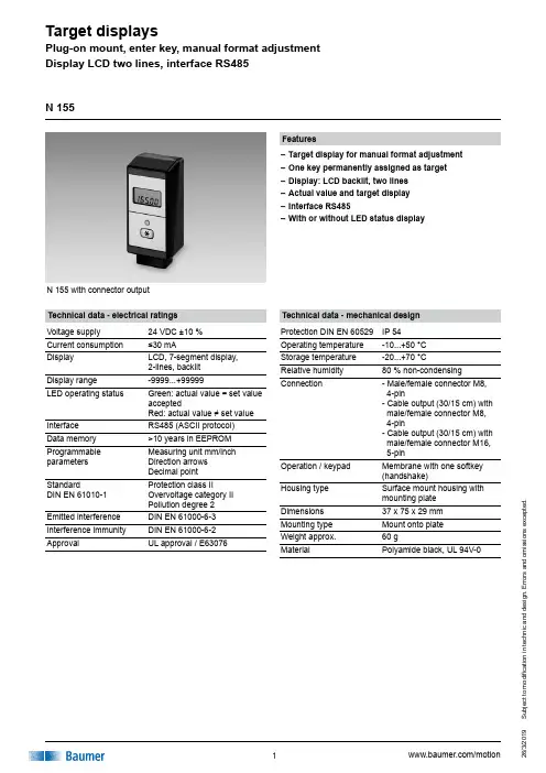
u b j e c t t o m o d i fi c a t i o n i n t e c h n i c a n d d e s i g n . E r r o r s a n d o m i s s i o n s e x c e p t e d .N 155 with connector output Features–Target display for manual format adjustment –One key permanently assigned as target –Display: LCD backlit, two lines –Actual value and target display –Interface RS485–With or without LED status displayTechnical data - electrical ratings Voltage supply 24 VDC ±10 %Current consumption ≤30 mADisplay LCD, 7-segment display,2-lines, backlit Display range -9999...+99999LED operating statusGreen: actual value = set value acceptedRed: actual value ≠ set value Interface RS485 (ASCII protocol)Data memory >10 years in EEPROM Programmable parameters Measuring unit mm/inch Direction arrows Decimal pointStandardDIN EN 61010-1Protection class IIOvervoltage category II Pollution degree 2Emitted interference DIN EN 61000-6-3Interference immunity DIN EN 61000-6-2ApprovalUL approval / E63076N 155Technical data - mechanical design Protection DIN EN 60529IP 54Operating temperature -10...+50 °C Storage temperature -20...+70 °CRelative humidity 80 % non-condensingConnection- Male/female connector M8, 4-pin- Cable output (30/15 cm) with male/female connector M8, 4-pin- Cable output (30/15 cm) with male/female connector M16, 5-pinOperation / keypad Membrane with one softkey (handshake)Housing type Surface mount housing with mounting plate Dimensions 37 x 75 x 29 mm Mounting type Mount onto plate Weight approx.60 gMaterialPolyamide black, UL 94V-0u b j e c t t o m o d i fi c a t i o n i n t e c h n i c a n d d e s i g n . E r r o r s a n d o m i s s i o n s e x c e p t e d .N 155Part number N 155.13X01DisplayB Horizontal at frontC Horizontal at front with LEDstatusVoltage supply 324 VDCConnection0Connector output M8 with male and female connector1Bottom cable output M8 2Rear cable output M8 3Bottom cable output M16Interface1RS485AccessoriesConnectors and cables 11034330Adaptor cable between cable connector M8 and female M16, 1 m (Z 178.A01)10159563Cable connector M8, 4-pin, without cable with integrated terminating resistor 120 Ω (Z 178.AW1)10160606Female connector M8, 4-pin, without cable (Z 178.B01)10159560Data and supply cable M8, 5 m (Z 178.D05)10160605Cable connector M8, 4-pin, without cable (Z 178.S01)10159739Coupling cable with M8 - M8, 1 m cable (Z 178.V01)10160607Data and supply cable, ø5 mm,4 cores, shielded, on 50 m drum (Z 178.050)The multicon spindle positioning system is completed by a target display indicating also positions of hand wheels, limits, linear units etc in close vicinity of the actuator. The backlit LCD display provides the editing engineer with the target parameters. A LED state indicator (red/green) that is optionally available enables comfortable visualization of the current adjustment status even from remote.The handshake key is saving the edited parameters. Serial interface RS485 enables network of maximum 32 target and spindle position displays with PC or PLC.Descriptionu b j e c t t o m o d i fi c a t i o n i n t e c h n i c a n d d e s i g n . E r r o r s a n d o m i s s i o n s e x c e p t e d .N 155M8 connector M16 connector Assignment Pin 1 Pin 5 Tx/Rx-, RS485Pin 2 Pin 4 Tx/Rx+, RS485Pin 3 Pin 1 Sensor supply +24 V Pin 4 Pin 2 Sensor supply 0 V243124312134521345M8 connectorM8 female connectorM16 connectorM16 female connectorTerminal assignmentu b j e c t t o m o d i fi c a t i o n i n t e c h n i c a n d d e s i g n . E r r o r s a n d o m i s s i o n s e x c e p t e d .N 155DimensionsBottom cable output, M8 and M16Connector male and femaleu b j e c t t o m o d i fi c a t i o n i n t e c h n i c a n d d e s i g n . E r r o r s a n d o m i s s i o n s e x c e p t e d .N 155DimensionsCable output rear, M8 / Cutout。

Benchtop Digital ThermometerSingle- and Ten-Channel ModelsU F ront Panel Programmable for 9 Thermocouple Calibrations U 0.2° Accuracy for Temperature U 0.01° Resolution U Min/Max StorageU Optional Analog OutputU Optional RS232 Communications U 115 Vac PowerThe MDS41 is a high-precision digital benchtop meter that accepts thermocouple inputs. The large, easy-to-read 13 mm (0.5") display features 6 digits with 0.01° resolution. The thermocouple input model has 9 thermocouple types in memory, any one of which can be selected through the front panel. The unit is switchable to °C/°F/K.The single-channel unit includes a universal rear connector which accepts either the miniature orstandard quick disconnect connector. The 10-channel MDSS uses screw terminals for temperature input.Optional scalable analog output is available and can be ordered as a 0 to 10 Vdc or 4 to 20 mA. The analog output provides a retransmission of the measured temperature for recorders or data loggers.Visit OMEGA for more information on the DP41 series.Red LED display and 115 Vac power are standard.For green LED display, add suffix “-GN” to model number, noadditional charge. For analog output, add suffix “-A” to model number.Note: The analog output for the MDSS models is for the displayed channel only. To order units with optional RS232 communications, add suffix “-S2” to model number, for additional cost.Ordering Example: MDS41-TC, single-channel benchtop indicator,thermocouple input.MDSS41-TC-GN, shown with TTSS-18U-6 transition junction and quick-disconnect thermocouples, sold separately.MDS41 SeriesShown smaller than actual size.MDS41-TC, shown with GKMQSS-125U-6miniature quick-disconnect probes, sold separately.as of 8/28/2017Economical SeriesThe DS (single-input) and the DSS (10-input) benchtop cases areOMEGA’s more economical cases. The DS and DSS cases maintain the versatility of panel meters and the portability of a benchtop. The DS and DSS are a beige color.** Insert thermocouple type or the meters specific range code.† For 10-channel models, communication port can only access input currently selected by 10-point selector switch on front of unit.Note: The benchtop models using the DP41-TC is programmable for any thermocouple type listed on the meter’s specification sheet.To order the DS version one channel replace the “MDS” in the model number with “DS”, and subtract from the MDS price.To order the DSS ten channel version replace the “MDSS” in the model number with “DSS”, and subtract cost from the MDSS price.Ordering Example: MDS116-JF, single-channel benchtop indicator, Type J thermocouple input, °F.OCW-2, OMEGACARE SM extends standard 3-year warranty to a total of 5 years.See table below for ordering information.MDS41-TC high-accuracy benchtop thermometer shown smaller than actual size, with KMTXL-125U-6 Type K molded transition joint thermocouple.OMEGACARE SM extended warranty program is available for models shown on this page. Ask your sales representative for full details when placingan order. OMEGACARE SMcovers parts, labor and equivalent loaners.。
自升式钻井平台环境载荷及结构强度吴小平;陆晟【摘要】对自升式钻井平台的环境载荷和结构强度进行了介绍.给出了环境载荷的主要组成部分及计算方法,对水动力载荷所引起的动态放大效应和由于平台水平位移而产生的P-DELTA效应加以了说明.针对拖航状态下桩腿承受很大的动力作用,还论述了油田拖航和远洋拖航状态下桩腿强度的计算方法,最后以谱分析方法为例,给出了结构疲劳强度分析的一般步骤.【期刊名称】《船舶与海洋工程》【年(卷),期】2010(000)003【总页数】6页(P36-40,51)【关键词】自升式钻井平台;环境载荷;拖航分析;疲劳分析【作者】吴小平;陆晟【作者单位】上海船舶研究设计院,上海200032;上海船舶研究设计院,上海200032【正文语种】中文【中图分类】U664.38+10 引言自升式海洋钻井平台在海上油气开发中得到广泛应用。
它由平台主体、升降装置以及若干(通常为3条到4条)桩腿组成。
平台主体与桩腿之间可通过升降装置实现相对移动,桩腿底部设有沉垫或桩靴与海底相接触。
作业时,桩腿降至海底,平台主体提升到海面以上一定高度,以避免波浪冲击。
拖航时,平台主体降至水面,依靠浮力支承,类似于船体。
此时,桩腿升至水面以上,通过拖航方式转移至新的作业地点。
自升式平台除了承受自身重量和可变载荷外,由于其工作环境的特殊性,还要时刻承受环境载荷的作用。
还有由环境载荷引起平台结构的变形和振动,进而导致附加载荷的产生。
例如:在环境载荷作用下,桩腿会发生变形,平台上部会发生很大的侧向位移,从而导致平台主体对桩腿底部产生附加弯矩。
另外,当平台的自然周期与波浪周期接近时,平台会发生强烈振动,引起很大的动载荷。
再者,由于环境载荷的持续作用,平台结构的内部将会发生疲劳损伤,久而久之,导致结构疲劳破坏。
所以,在自升式平台结构设计过程中,要多方面、综合考虑环境载荷的影响。
1 环境载荷海洋环境载荷主要来源于风、浪、流、冰、地震等方面。
IACS INTERNATIONAL ASSOCIATIONOF CLASSIFICATION SOCIETIESFORM 1Notice of Reservations Filed ForIACS Unified Requirementsas at June 2009Page 1(Printed on 20/08/2009)UR A1 EquipmentUR Clause Society ReservationVersionA1 A1.2ABS For ships less than 40 m in length, ABS Rules allow with certainconditions wire ropes in lieu of chains.1981A1 A1.3.1ABS ABS' requirements for anchoring equipment for tugs of unrestrictedservice are less than prescribed in UR A1.3.1.3/1994UR A2 Shipboard fittings and supporting hull structures associated with towing and mooring on conventional vesselsUR Clause Society ReservationVersionA2A2.1.6A2.2.6GL GL reserves the right to lower the SWL to be marked on shipboard mooring fittings by factor 1.5. (SWLGL=SWLA2/1.5)The reason for GL’s reservation is, GL do not support a safety conceptutilizing a safety factor of 1.0 for the fittings against the breaking load ofthe ropes attached to the fittings. This has been raised during discussionin Hull Panel several times without feed back.Rev.3UR D4 Self-elevating drilling unitsUR Clause Society ReservationVersionD4D4.4LR Damage stability requirements are not included in the Rules and theextent of defined damage is to be in accordance with Flag requirements.Rev.2 1996UR D5 Column stabilized drilling unitsUR Clause Society ReservationVersionD5D5.6LR Damage stability requirements are not included in the Rules and theextent of defined damage is to be in accordance with Flag requirements.Rev.3 1996UR D6 Surface type drilling unitsUR Clause Society ReservationVersionD6D6.4LR Damage stability requirements are not included in the Rules and theextent of defined damage is to be in accordance with Flag requirements.1979UR E7 CablesUR Clause Society ReservationVersionE72DNV Partly implemented.The following IEC standards is not referred: 60092-373, 60092-374 (asthese standards are beyond our scope)Rev.3 May 2006E73RS RS reserves its position on acceptance of cables other than thosespecified in item 2 of UR E7. These cables will be subject to specialconsideration by RS in each particular case.Rationale: RS Rules requires that cables should have RS type approval.Rev.3 May 2006UR E10 Test Specification for Type ApprovalUR Clause Society ReservationVersionE1010.1ABS Not applied to all internal communication equipment as listed in 10.1.4/May 2004UR E11 Unified requirements for systems with voltages above 1kV up to 15kVUR Clause Society ReservationVersionE1111 1.3LR HV-LV segregation limited to electric cablesRev.2 July 2003E1111 2.2.2LR Specific IP rating mentioned in the UR are not included in LR Rule.Rev.2 July 2003E1111 2.2.3LR Specific IP rating mentioned in the UR are not included in LR Rule.Rev.2 July 2003E1111 2.2.4LR Specific IP rating mentioned in the UR are not included in LR Rule Rev.2 July 2003E1111 2.3.2LR IEC creepage distances and 25 mm/kV minimum mentioned in the URare not included in the rulesRev.2 July 2003E1111 2.4.1LR LR rule applies to all generators of rating 1500kVA and aboveirrespective of voltage ratingRev.2 July 2003E1111 2.4.2LR LR rule applies to fault currents in excess of 5A in impedance earthedcircuits onlyRev.2 July 2003E1111 2.4.5LR LR rule permits the use of suitable fuses for overload protection Rev.2 July 2003E1111 3.2LR LR rule applies to all generators and motors utilised for electricpropulsion applications only irrespective of voltage rating Rev.2 July 2003E1111 4.1LR LR rules do not require low liquid level alarm and trip or load reductionfacilities mentioned in the URRev.2 July 2003E1111 6.2.2LR LR rules do not specifically require locking facilities on circuit breakersfor high voltage applications mentioned in the URRev.2 July 2003E1111 6.2.3LR LR rules do not specifically require the provision of shutters mentionedin the URRev.2 July 2003UR E13 Test requirements for Rotating MachinesUR Clause Society ReservationVersionE13 4.8 Table 1item 8DNV Partly implementedOverspeed test, Applicable for type test only.Corr.1 May 04/Rev.1 May 01E13E13/3 Table 1IRS Overspeed tests for generators and motors are not considered necessaryduring routine testing, also these are difficult to put in practice due toreluctance from manufacturers. As far as type tests are concerned,overspeed test is included in IRS Rules.Rev.1 May 2001UR E20 Installation of electrical and electronic equipment in engine rooms protected by fixed water-based local application fire-fighting systems (FWBLAFFS)UR Clause Society ReservationVersionRev.5 Nov 2005E20All DNV Partly implementedIn accordance with IMO FP48 WP4, DNV has made these requirementsapplicable for “Installation of electrical and electronic equipment inengine rooms protected by fixed water-based local applicationfire-fighting systems” operating with salt water systems only.May 04E20-NK NK admits to apply UR E20 for electrical and electronic equipmentlocated within areas protected by FWBLAFFS and those within adjacentareas exposed to direct spray having a degree of protection of IP22which got a satisfactory result of actual test using fresh water.UR F2 Aluminium Coatings on Board Oil Tankers and Chemical TankersUR Clause Society ReservationVersion1/1998F2F2ABS ABS is not convinced that the restrictions on use of aluminiumcoatings/aluminized pipe are justified by the perceived hazards. ABSdoing research on the matter.UR F5 Pump room alarmsVersionUR Clause Society ReservationRev.1 1973F5Entirely LR LR’s policy is not to include statutory requirements in the Rules.UR F7 Portable instruments for measuring oxygen and flammable vapour concentrations VersionUR Clause Society ReservationRev.2 May 1999F7Partly LR LR Rules do not require portable oxygen analysers for single hulltankers.UR F9 Lighting and sighting ports in pump room/engine room bulkheadsUR Clause Society ReservationVersion1971F9Entirely LR As advised in Mr Wade’s telefax to Council Members dated 12 May1995, the requirements for fire protection, detection and extinction forships covered by the SOLAS Convention were removed from LR Rulesand Regulations for the Classification of Ships with effect from 26 July1995. Compliance with SOLAS is a pre-requisite for classification.However, the Rules do contain requirements for fire protection,detection and extinction for cargo ships of less than 500 gross tons butUR F9 is no longer implemented in these Rules as the use of lightingand sighting ports is now obsolete in our experience.UR F34 Low Pressure Carbon Dioxide Smothering SystemsVersionUR Clause Society ReservationRev.1 1989F34All DNV N/A To be deleted (replaced by IACS UI SC170)F34Entirely LR As advised in Mr Wade’s telefax to Council Members dated 12 May Rev.1 19891995, the requirements for fire protection, detection and extinction forships covered by the SOLAS Convention were removed from LR Rulesand Regulations for the Classification of Ships with effect from 26 July1995. However, compliance with SOLAS is a pre-requisite forclassification.Accordingly, UR F34 is not implemented in LR Rules and Regulationsfor the Classification of Ships.The Rules do, however, contain requirements for fire protection,detection and extinction for cargo ships of less than 500 gross tons andfor fishing vessels of between 12 and 45 metres in length.UR I2 Structural Requirements for Polar Class ShipsUR Clause Society ReservationVersionI2I2.13GLGL reserves its position to perform buckling strength calculations on the basis of DIN 18800Rev.1UR K3 Keyless fitting of propellers without ice strengtheningUR ClauseSociety ReservationVersionK3AllDNVFull Reservation on existing K3.The proposed planned revision 5 of the IACS working group was implemented in the DNV Rules in January 2006.Corr.2 June 1998UR M2 Alarm Devices of Internal Combustion EnginesUR Clause Society ReservationVersionM2M2ABSABS Rules only require plan review and survey of engines of 100 kW and over. Therefore ABS does not implement this UR for engines in the range 37 to 100 kW.1971UR M3 Speed governor and overspeed protective deviceUR ClauseSociety Reservation VersionM32.3DNVPartly implemented 3 steps in lieu of 2Rev.5 Feb 06UR M5 Mass production of internal combustion engines, procedure for inspectionUR Clause Society ReservationVersionM5M5.1ABSABS does not limit its application of UR M5 for mass production of internal combustion engines to those having cylinder bore not exceeding 300 mm.1/1987M5All DNVFull reservation.DNV plans to amend and align its reference documents (rules, etc.) in line with the outcome from the IACS Project Team established to review the relevant requirements.Rev. 1 1987M5M5.1NKNK admits to apply UR M5 for mass production of internal combustion engines having cylinder bore not exceeding 320mm.Rev.1/1987UR M6 Test pressures for parts of internal combustion enginesUR ClauseSociety ReservationVersionM6AllDNVFull reservation.DNV plans to amend and align its reference documents (rules, etc.) in line with the outcome from the IACS Project Team established to review the relevant requirementsRev.3 May 1998UR M14 Mass production of internal combustion engines: definition of mass productionUR Clause Society ReservationVersionM14AllDNVFull reservation.DNV plans to amend and align its reference documents (rules, etc.) in line with the outcome from the IACS Project Team established to review the relevant requirements.1973UR M18 Parts of internal combustion engines for which material tests are requiredUR Clause Society ReservationVersionM18M18.3ABS For repair of IC engines with bores 300mm or less, ABS does not insist on certification of connecting rods.1972M18AllDNVFull reservation.DNV plans to amend and align its reference documents (rules, etc.) in line with the outcome from the IACS Project Team established to review the relevant requirementsRev.4 Jun 2000M18Partly LRThis is a question of mass produced and non-mass produced engines.LR Rules do not refer to mass produced engines; the requirements are based on bore size alone, i.e. less than or greater than 400 mm.Rev.4 Jun 2000UR M19 Parts of internal combustion engines for which nondestructive tests are requiredUR Clause Society ReservationVersionM19AllDNVFull reservation.DNV plans to amend and align its reference documents (rules, etc.) in line with the outcome from the IACS Project Team established to review the relevant requirements.1974UR M21 Mass production of internal combustion engines: type test conditionsUR ClauseSociety ReservationVersionM21AllDNVFull reservation.DNV plans to amend and align its reference documents (rules, etc.) in line with the outcome from the IACS Project Team established to review the relevant requirements.1974, Corr. Sept 2003UR M23 Mass production of engines: Mass Produced Exhaust Driven TurbochargersUR ClauseSociety ReservationVersionM23AllDNVFull reservation.DNV plans to amend and align its reference documents (rules, etc.) in line with the outcome from the IACS Project Team established to review the relevant requirements.Rev. 3 1991M23M23.1RINAThis UR is applied by RINA to turbochargers fitted on diesel engines having a power of 1000 kW and above.For the others turbochargers (i.e. fitted on diesel engines having a power less than 1000 kW) RINA requires they are delivered with the works'certificate relevant to the bench running test and the hydrostatic test.Rev.3 1991UR M24 Rules concerning use of crude oil or slops as fuel for tanker boilersUR ClauseSociety ReservationVersionM24M24BV This UR refers to offshore Rules only.Rev.1 1976M24M24NK NK does not apply crude oil or slops as fuel for tanker boilers.Therefore, this UR will not be implemented1/1976M24M24RINAThis UR was introduced in a RINA Rule for the assignment of a special class notation (in force since 1980) never applied. The above mentioned RINA Rule has consequently been deleted.1/1976UR M32 Definition of diesel engine typeURClauseSocietyReservationVersionM32Note 1DNV Partly implemented.DNV practices this requirement with the exception of Note 1, theconditions alter slightly as well as we use other parameters than power,namely cylinder pressure and speed.1979UR M34 Scantlings of coupling flangesUR Clause Society ReservationVersionM34All DNV Full reservation.- M34.1: DNV uses combined stress criteria with credit for frictiontorque instead of the UR diameter formulae.- M34.3: DNV rules deviate when r/d>0.08- M34.4: DNV rules have no direct restriction to r/d, but shaftcalculations will tend to limit this ratio.1980UR M35 Alarms, remote indications and safeguards for main reciprocating I.C. engines installed in unattended machinery spacesUR Clause Society ReservationVersionM35Table 1 Item6Table 1 Item8Table 2 Item2DNV Partly introduced.The DNV rules are basically in line with UR M35, however deviate insome respect:- Table 1 Item 6 "Oily contamination of engine cooling water system"- Table 1 Item 8 "Scavenge air system"; DNV rules does not requirescavenge air receiver water level- Table 2 Item 2 "Oil mist concentration in crankcase"; DNV rulesaccept also alternatives to the oil mist detectorRev.4 1999UR M44 Documents for the approval of diesel engines UR Clause Society Reservation VersionM44Item 22Item 27DNV Partly Implemented- Item 22: Material specifications of main parts with information onNDT and pressure tests. DNV rules request this, but in general forinformation only, not for approval. NDT is required for approval onlyfor crankshafts and connecting rods.- Item 27: Cooling water system. DNV rules request this, but forinformation only, not for approval.Reduced extent for cylinder bores less than 150 mm.Rev.7 May 2004UR M51 Programme for trials of i.c. engines to assess operational capabilityUR Clause Society ReservationVersionM51M51.2.1.3b ABS Test at 110% power for 30 minutes is not in ABS Rules.1987M51M51.2.2ABS This paragraph for special operating conditions is not in the ABS Rules.1987M51 1.12.1DNV Partly Implemented- 1.1: 25% test is taken out in the DNV rules.- 2.1: Reduced testing hours in DNV rules for small main engines.- 2.1: For aux. engines, DNV rules specify test time 1 hour, whileIACS require 4 hours.Rev.2 Jul 2003UR M52 Length of aft stern bush bearingUR Clause Society ReservationVersionM522DNV Partly implemented.DNV rules do not indicate any direct lower limit for bearing length. Thislength however, will be limited by load and damping characteristicswith respect to whirling.1986UR M56 Marine Gears - Load Capacity of Involute Parallel Axis Spur and Helical GearsUR ClauseSociety ReservationVersionM56All DNVPartly implemented.DNV use and accept alternative criteria for calculation of gears. Very much in line with recognised international standards. DNV hasimplemented updates from ISO 6336 which is the source for both M56and DNV. M56 has not been updated accordingly.Rev.1 1994Corr 1996M56M56.1.2RINARINA does not consider design approval of gears having rating less than 220 kW for main propulsion or 110 kW for essential service auxiliaries necessary, taking into account that they are mass produced according to standardized design criteria widely experienced in service and built by specialized manufacturers.RINA, in any case, requires factory acceptance tests and sea trials to be performed for gears intended for main propulsion and essential auxiliaries.Rev.1 1994/Corr. 1996UR M58 Charge air coolersUR Clause Society ReservationVersionM58AllDNVFull reservation.DNV rules do not request works material certificates, and accept hydraulic testing to be carried out at maximum working pressure only.1994UR M59 Control and safety systems for dual fuel diesel enginesUR Clause Society ReservationVersionM593.1,3.2 (1) and (2),4.1,8.1,9.1.2.cDNVPartly implemented.UR M59 has been partly implemented in the DNV rules, do however not specifically list all requirements stated in the UR. (This applies to UR item nos. M59.3.1, 59.3.2 (1) and (2), 59.4.1, 59.8.1 and 59.9.1.2.c.)M59 will continue to be evaluated in machinery panel.1996UR M60 Control and Safety of Gas Turbines for Marine Propulsion UseURClauseSocietyReservationVersionM601.1,1.2,2.2DNVPartly implemented.The DNV rules deviate slightly from IACS UR M60 concerning monitoring requirements as follows:- Ref. UR M60.1.1.DNV rules do not require a specific maximumoverspeed limit of 15%. DNV requirements are related to preventing the turbine speed from exceeding the maximum permissible speed as defined by the Manufacturer.- Ref. UR M60.1.2. DNV do not require separate speed governors for speed control and over speed protection. However, the control system must be capable of controlling the speed due to sudden turbine load drop without activating the over speed shut down function.- Ref. UR M60.2.2. DNV rules request “step to idle” (not “shut down”)for h) “excessive high vacuum pressure at compressor inlet”.DNV rules have no action requirements related to exhaust temperature.DNV does not require automatic shut down due to item e) “excessive axial displacement”. DNV only require that applications which may experience thrust load directional variations must be provided with an axial proximity probe in the high speed driven string. At the next rule revision DNV will implement a requirement for alarm in case ofchanged thrust load direction. DNV considers this to provide the highest vessel safety level, as shutdowns not strictly needed are detrimental to vessel safety.- Ref. UR M60.3, table 1. DNV rules do not request alarm for “oil fuel temperature” and “oil fuel supply pressure”. At the next rule revision DNV will implement a requirement for alarm related to low oil fuel temperature. This to be applicable for turbines running on oil fuels where oil fuel heaters are required to avoid viscosity problems.1997UR M62 Rooms for emergency fire pumps in cargo shipsUR ClauseSociety ReservationVersionM62ABSThe UR cannot be uniformly implemented until "adequately" isquantified and therefore is not being implemented by ABS at this time.Feb 2002UR N1 One man bridge operated shipsUR Clause Society ReservationVersionN1AllIRSRequirements concerning navigation are not presently part of IRS Rules.Also, there are no ships of this type in IRS class.1992UR P2 Rules for Piping Design, Construction and TestingUR ClauseSociety ReservationVersionP2P2.5.5.5& Table 4ABSPost weld heat treatment for oxyacetylene welding is not in ABS Rules.1/1987 &Corr.Nov 2001P2 2.3.1LR Pipe requirements given in Materials Pt 2 which is called up UR P2 Rules for Piping Design, Construction and Testing - 2.3 MaterialsUR Clause Society ReservationVersion Rev.2 Nov 2001P2 2.3.3LR No restriction on systems in LR RulesRev.2 Nov 2001P2 2.3.4LR Design temperature is common, no mention of vibration or shock Rev.2 Nov 2001P22.3.4LRThe upper pressure limit in the UR is not given by LR nor is the prohibition from manifold useRev.2 Nov 2001P2 2.5.3.2LR Use of tack welds not covered UR P2 Rules Piping Design, Construction and Testing - 2.5 WeldingUR Clause Society ReservationVersion Corr. Nov 2001P2 2.5.4LR 0.3 Mo alloy steel not in RulesCorr. Nov 2001P2 2.5.5.5LR Requirements for heat treatment of oxy acet welded pipes not given Corr. Nov 2001P2Table 3 LR 0.3mo steel not included and slightly tighter tempsCorr. Nov 2001P2Table 3LR0.3mo steel not included note 3 acted on, notes 1 & 2 do not appear to be coveredCorr. Nov 2001P22.6.1.1.1.2LRLR do not specify a min of 10% or the type of testingUR P2 Rules for Piping Design, Construction and Testing - 2.6 Non destructive testing of welds and acceptance criteriaUR Clause Society ReservationVersion1987P22.8.1LRMembrane stress limitation not quotedUR P2 Rules for Piping Design, Construction and Testing - 2.8 Hydrostatic tests of pipingUR Clause Society ReservationVersion Rev.1, Corr Nov 2001UR P2.7 Rules for Piping Design, Construction and Testing - Types of connectionsUR ClauseSociety ReservationVersionP2.7P2.7.4NKNK admits the use of slip-type slip-on joints to steam piping of which design pressure is 1.0 MPa or less, for cargo heating on open decks in tankers.Rev.2 Nov 2001UR P6 Shell Type Exhaust Gas Heated Economizers that may be isolated from the steam plant systemUR ClauseSociety ReservationVersionP6P6.3.2P6.3.3P6.3.3.1P6.3.4ABSThe ABS technical committee considers that the requirements go beyond the recommendations of the MAIB and would imposeunwarranted technical design changes on safety valve manufacturers.May 2005P6P6.3.2P6.3.3P6.3.3.1P6.3.4RINANo sufficient experience is available on construction and installation of special design safety valves and bursting discs.May 2005UR S4 Criteria for the use of high tensile steel with minimum yield Stress of 315 N/mm 2, 355N/mm 2 and 390 N/mm 2UR ClauseSociety ReservationVersionS4S4ABSABS reserves against the k-factor for steel with a yield point of 390N/mm2 for the longitudinal strength calculation of Container Carriers with plate thickness greater than 51mm when additional special analyses are applied.Rev.2 Apr 2007S4S4DNVPartly implementedDNV reserves against application of the k-factor for steel with minimum yield stress = 390 N/mm2 for ships with DNV class notation Container Carrier provided that a fatigue assessment is performed.Rev.2 Apr 2007S4S4GLGL reservation against the k-factor for steel with a yield point of 390N/mm (2008)Rev.2UR S6 Use of steel grades for various hull members - ships of 90m in length and aboveUR Clause Society ReservationVersionS6S6.2 & 6.3ABSUntil further experiences are gained, service temperatures cooler than -40C will be in the Rules as guidance. Design temperature for members in the current ABS Rules is being retained pending unification of polar ship requirements.2/1996S66.2, 6.3RSRS has implemented UR S6 with regard to item 6.1 only. National requirements similar to S6.2 have been implemented in RS Rules.2/19963/May 20024/July 20035/Sept 2007UR S7 Minimum Longitudinal Strength StandardsUR Clause Society ReservationVersionS7S7.1RSWith respect to item 7.1, RS uses different criteria for ships in service for calculating minimum longitudinal strength standards. Thisreservation however does not apply to tankers with length over 130 m.3/1989UR S10 Rudders, sole pieces and rudder hornsUR ClauseSociety ReservationVersionS10S10.8.3GL For self-lubricating gearings, clearances less than 1.5 mm on diameter may be accepted on the basis of the manufacturer’s specification.Rev.1 1990S10RSPartially implemented, but rudder strength calculation method in RS Rules is more detailed and universal.Rev.1 1990Corr.July 2003UR S11 Longitudinal Strength StandardUR ClauseSociety ReservationVersionS11S11.5ABS For certain type/size ships, ABS accepts alternate approach involving ultimate strength assessment.Rev.1 1993S11S11.5BVBuckling strength has not been implemented. Equivalent criteria have been introduced to be coherent with other parts of BV Rules with regard to loads and corrosion margins.Rev.1 1993S11S11.5GL GL reserves its position to perform buckling strength calculations on the basis of DIN 18800.Rev.5 Jan 2006S11S11.5NKStructural members subject to hull girder bending and shear stress applying in S11.5.1 for buckling strength have partly been applied in NK rules but all longitudinal members have not been applied.Rev.5 Jan 2006S11S11RINAThis UR S11 is substantially applied. In the Rules for the classification of ships effective from 1st June 2000, the UR formulation has been modified to make it consistent with the general rule criteria, however without significant modifications to the final results.Rev.1 1993UR S14 Testing Procedures of Watertight CompartmentsUR ClauseSociety ReservationVersionS14S14.3NKNK has partly implemented this UR because some requirements which are considered impracticable still remain in S14.3.Rev.2 May 2001UR S17 Longitudinal strength of hull girder in flooded condition for single side skin bulk carriers URClause Society Reservation Version S17S17.5ABS This paragraph requires that permissible axial buckling stress meet S11.This is being adhered to for deck and bottom plating. When this isapplied to a Panamax bulk carrier, 14.5 mm topside tank bottom platinghad to be increased to 17 mm. We do not think this was / is the intent ofS17 and are applying axial stress check only to the deck and bottom structures and request that UR be changed to clarify its applicability.1/1997S17S17.5GLGL reserves its position to perform buckling strength calculations on thebasis of DIN 18800.Rev.7 Feb 2006UR S21 Evaluation of Scantlings of Hatch Covers and Hatch Coamings of Cargo Holds of Bulk Carriers, Ore Carriers and Combination Carriers (Rev.4)URClause Society Reservation Version S21S21.3.6GL GL reserves its position to perform buckling strength calculations on thebasis of DIN 18800.Rev.4 Jul 04/Corr.1 Oct 04UR S26 Strength and securing of small hatches on the exposed fore deckURClause Society Reservation Version S261.4DNV Partly implemented.The requirement will not be retroactively implemented for all ships.Rev.3 Aug 06S26S26.3.2NK For ships which will be less than 10 years of age on 1 January 2004, NKaccepts postponement to the date of the first scheduled intermediate orspecial survey after that date in such a case where an intermediate orspecial survey of the ship is not scheduled between 1 January 2004 andthe date on which the ship reaches 10 years of age. It is same as the duedate for ships, which will be 10 years of age or more on 1 January 2004.Because it is impracticable for ships in question to implement this clauseof the UR Rev.3 Aug 06UR S27 Strength requirements for fore deck fittings and equipmentURClause Society Reservation Version S27S27.3.2NK Same as the reservation of UR S26.3.2.Rev.4 Nov 04UR S30 Cargo hatch cover securing arrangements for bulk carriers not built in accordance with UR S21URClause Society Reservation Version S30S30.1.2NK Same as the reservation of UR S26.3.2.Rev.1 Aug 03UR S31 Renewal criteria for side shell frames in single side skin bulk carriers and OBO carriers not built in accordance with UR S12 Rev.1 or subsequent revisionsURClause Society Reservation Version S31S31.1NK Same as the reservation of UR S26.3.2Rev.4 Apr 2007UR W26 Requirements for welding comsumables for aluminium alloysUR Clause Society Expected Implementation DateVersion。
DNV Codes and Standards16 June 2006DNV Offshore CodesDNV Offshore Codes consist of a three level hierarchy of documents:— Offshore Service Specifications. Provide principles and procedures of DNV classification, certification, verification and consultancy services.—Offshore Standards. Provide technical provisions and acceptance criteria for general use by the offshore industry as well as the technical basis for DNV offshore services.—Recommended Practices. Provide proven technology and sound engineering practice as well as guidance for the higher level Offshore Service Specifications and Offshore Standards.Slide 2Hierarchy of DNV Codes ServiceSpecifications OffshoreStandards RecommendedPractices Operation Construction Internationallyrecognised codes DesignSlide 3Offshore Standards A: Quality and Safety Methodology B: Materials Technology C: Structures D: Systems E: Special FacilitiesF: Pipelines and Risers G: Asset Operation H: Marine Operation J: Wind TurbinesA B C D E FSlide 4Quality and Safety MethodologyAOFFSHORE STANDARD DNV-OS-A101SAFETY PRINCIPLES AND ARRANGEMENTJANUARY 2001Contents: Design Principles and Accidental Loads Arrangement Hazardous Area Classification Emergency Shutdown (ESD) Principles Escape and Communication App: Guidelines for Formal Safety AssessmentSlide 5Materials TechnologyBOFFSHORE STANDARD DNV-OS-B101METALLIC MATERIALSJANUARY 2001Contents: Rolled Steel for Structural Application Steel Tubes and Pipes Steel Forgings Steel Castings Aluminium Alloys Testing ProceduresSlide 6StructuresCOFFSHORE STANDARD DNV-OS-C101: Design of Offshore Structures, General (LRFD method) DNV-OS-C102: Structural Design of Offshore Ships DNV-OS-C103: Structural Design Column-stabilised Units (LRFD method) DNV-OS-C104: Structural Design of Self-elevating Units (LRFD method) DNV-OS-C105: Structural Design of Tension-leg Units (LRFD method) DNV-OS-C106: Structural Design of Deep-draught Units (LRFD method) DNV-OS-C201: Structural Design of Offshore Units (WSD Method)Slide 7StructuresCOFFSHORE STANDARDDNV-OS-C301: Stability and Watertight Integrity DNV-OS-C401: Fabrication and Testing of Offshore Structures DNV-OS-C501: Composite Structures DNV-OS-C502: Offshore Concrete Structures DNV-OS-C503: Offshore Concrete LNG Structures Slide 8SystemsDOFFSHORE STANDARDDNV-OS-D101: Marine and Machinery Systems and Equipment DNV-OS-D201: Electrical Installations DNV-OS-D202: Instrumentation and Telecommunication DNV-OS-D301: Fire Protection Slide 9Special FacilitiesEOFFSHORE STANDARDDNV-OS-E101: Drilling Plant DNV-OS-E201: Oil and Gas Processing Systems DNV-OS-E301: Position Mooring DNV-OS-E401: Helicopter Decks DNV-OS-E402: Diving Systems Slide 10Pipelines and RisersFOFFSHORE STANDARDDNV-OS-F101: Submarine Pipeline Systems DNV-OS-F201: Dynamic RisersSlide 11Recommended Practices A: Quality and Safety Methodology B: Materials Technology C: Structures D: Systems E: Special Facilities F: Pipelines and Risers G: Asset OperationABCDE F G HH: Marine Operations J: Wind TurbinesSlide 12Recommended Practices - List of Publications(1)Quality & Safety Methodology – A DNV-RP-A201 DNV-RP-A202 DNV-RP-A203 DNV-RP-O401Standard Documentation Types (11-2000) Documentation of Offshore Projects (01-2001) Qualification Procedures for New Technology (09-2001) Safety and Reliability of Subsea Systems (04-1985)Materials – BDNV-RP-B401Cathodic Protection Design (1993)RECOMMENDED PRACTICE DNV-RP-A201Structures – C DNV-RP-C102 DNV-RP-C103 DNV-RP-C201 DNV-RP-C202 DNV-RP-C203 DNV-RP-C204 DNV-RP-O501Ship Shaped Offshore Structures (02-2002) Column Stabilised Units (10-2001) Buckling Strength of Plated Structures (10-2002) Buckling Strength of Shells (05-2000) Fatigue Strength Analysis (10-2001 ) Design against Accidental Loads Erosive Wear in Piping Systems (1993)TITLEJANUARY 2001Systems - DSpecial Facilities – E DNV-RP-E301 DNV-RP-E302 DNV-RP-E305 DNV-RP-E401Design and Installation of Fluke Anchors in Clay (05-2000) Design and Installation of Drag-in Plate Anchors in Clay (05-2000) Onbottom Stability of Submarine Pipelines (10-1988) Naval Rescue SubmersiblesSlide 13Recommended Practices - List of Publications (2)Pipelines & Risers – F DNV-RP-F101 DNV-RP-F102 DNV-RP-F103 DNV-RP-F104 DNV-RP-F105 DNV-RP-F106 DNV-RP-F107 DNV-RP-F108 DNV-RP-F201 DNV-RP-F202 DNV-RP-F203 DNV-RP-F204 DNV-RP-F205Corroded Pipelines (04-1999) Pipeline Field Joint Coating and Field Repair of Pipeline Ext. Coating Cathodic Protection of Submarine Pipelines by Galvanic Anodes Mechanical Pipeline Couplings (09-1999) Free Spanning Pipelines (03-2002) Factory Applied Pipeline Coatings for Corrosion Control (03-2000) Risk Assessment of Pipeline Protection (03-2001) Fracture Control for Pipeline Installation Methods Introducing Cyclic Plastic Strain Design of Titanium Risers Composite Risers Riser Collision (under development) Riser Fatigue Global Performance Analysis of Deepwater Floating StructuresRECOMMENDED PRACTICE DNV-RP-A201TITLEJANUARY 2001Asset Operation - G DNV-RP-G101 DNV-RP-H101 DNV-RP-H102Risk Based Inspection of Offshore Pressurised Equipment (01-2003) Risk Management in Marine and Sub-sea Operations (01-2003) Marine Operations During Removal of Offshore InstallationsSlide 14Drill Plant: Certification/ Classification OSS-101Helideck: Certification/ Classification OSS-101 OSS-102Production Plant: Risk Based Verification: OSS-303DRILLING UNIT Classification: OSS-101FPSO Classification: OSS-102 Class based on risk ass. : OSS-121 LNG/LPG: OSS-103 Mooring: Certification: OSSE301Risers: Certification/ Verification: OSS-302Wire rope: Certification OSS-102FSO Classification: OSS-102 LNG/LPG: OSS-103 Pipeline: Certification/ Verification: OSS-301Anchors: Certification/Verification RP-E302Slide 15Drill Plant: OS-E201Helideck: OS-E401Production Plant: OS-E201SEMI-SUB Safety: OS-A101 Materials: OS-B101 Hull: OS-C101 OS-C103 RP-C103 OS-C-401 Stability: OS-C301 Marine/Machinery: OS-D101 Electrical: OS-D201 Instrumentation: OS-D202 Fire Safety: OS-D301FPSO Safety: OS-A101 Materials: OS-B101 Hull: OS-C101 OS-C102 RP-C102 OS-C-401 Stability: OS-C301 Marine/Machinery: OS-D101 Electrical: OS-D201 Instrumentation: OS-D202 Fire Safety: OS-D301Risers: OS-F201 RP-F201 RP-F202Wire rope: OS-E303 Mooring: OS-E301 Chain: OS-E302 Anchors: RP-E301 RP-E302 Pipeline: OS-F101 RP-F101 RP-F104 RP-F105 RP-F106 RP-F107 RP-F108FSO Safety: OS-A101 Materials: OS-B101 Hull: OS-C101 OS-C102 RP-C102 OS-C-401 Stability: OS-C301 Marine/Machinery: OS-D101 Electrical: OS-D201 Instrumentation: OS-D202 Fire Safety: OS-D301Wellheads: OS-E101Slide 16Offshore Rules and Standards onlineAccess for external usersFrom DNV internet home page (), select:Viewing area (free access for viewing) Offshore member servicesLog in to "Offshore Member Services" on the left hand menu: - Username: DNVOFFSHORECODES - Password: Offshore05Slide 17Offshore Rules and Standards onlineSlide 18THANK YOUSlide 19。
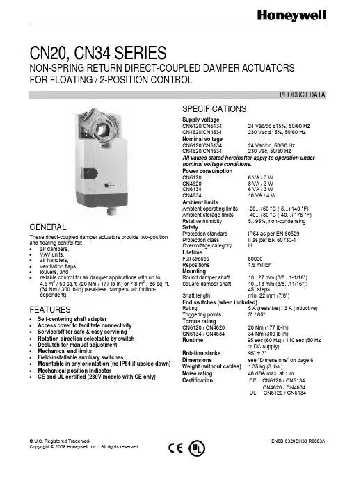
® U.S. Registered TrademarkEN0B-0320CH33 R0803ACopyright © 2008 Honeywell Inc. • All rights reservedCN20, CN34 SERIESNON-SPRING RETURN DIRECT-COUPLED DAMPER ACTUATORS FOR FLOATING / 2-POSITION CONTROLPRODUCT DATAGENERALThese direct-coupled damper actuators provide two-position and floating control for: • air dampers, • VAV units, • air handlers, • ventilation flaps, • louvers, and• reliable control for air damper applications with up to4.6 m 2 / 50 sq.ft. (20 Nm / 177 lb-in) or 7.8 m 2 / 85 sq. ft. (34 Nm / 300 lb-in) (seal-less dampers; air friction-dependent).FEATURES• Self-centering shaft adapter• Access cover to facilitate connectivity • Service/off for safe & easy servicing • Rotation direction selectable by switch • Declutch for manual adjustment • Mechanical end limits• Field-installable auxiliary switches• Mountable in any orientation (no IP54 if upside down) • Mechanical position indicator•CE and UL certified (230V models with CE only)SPECIFICATIONSSupply voltageCN6120/CN6134 24 Vac/dc ±15%, 50/60 Hz CN4620/CN4634 230 Vac ±15%, 50/60 Hz Nominal voltage CN6120/CN6134 24 Vac/dc, 50/60 Hz CN4620/CN4634 230 Vac, 50/60 HzAll values stated hereinafter apply to operation under nominal voltage conditions. Power consumption CN6120 6 VA / 3 W CN4620 8 VA / 3 W CN6134 6 VA / 3 W CN4634 10 VA / 4 W Ambient limitsAmbient operating limits -20...+60 °C (-5...+140 °F) Ambient storage limits -40...+80 °C (-40...+175 °F) Relative humidity 5...95%, non-condensing SafetyProtection standard IP54 as per EN 60529 Protection class II as per EN 60730-1 Overvoltage category III Lifetime Full strokes 60000Repositions 1.5 million MountingRound damper shaft 10...27 mm (3/8...1-1/16") Square damper shaft 10...18 mm (3/8...11/16");45° steps Shaft length min. 22 mm (7/8") End switches (when included) Rating 5 A (resistive) / 3 A (inductive) Triggering points 5° / 85° Torque rating CN6120 / CN4620 20 Nm (177 lb-in) CN6134 / CN4634 34 Nm (300 lb-in) Runtime 95 sec (60 Hz) / 110 sec (50 Hzor DC supply)Rotation stroke 95° ± 3° Dimensions see "Dimensions" on page 6 Weight (without cables) 1.35 kg (3 lbs.) Noise rating 40 dBA max. at 1 mCertification CE CN6120 / CN6134 CN4620 / CN4634UL CN6120 / CN6134CN20, CN34 SERIES DAMPER ACTUATOR FOR FLOATING AND 2-POS CONTROLEN0B-0320CH33 R0803A 2MODELSModel # DescriptionCN6120A1002 20Nm,24Vac/Vdc, Floating/2-position control, Non-Spring Return, No feedback and without aux. Switch CN4620A1001 20Nm,230V,Floating/2-position control, Non-Spring Return, No feedback and without aux. SwitchCN6134A1003 34Nm,24Vac/Vdc, Floating/2-position control, Non-Spring Return, No feedback and without aux. Switch CN4634A1001 34Nm,230Vac, Floating control/2-position, Non-Spring Return, No feedback and without aux. SwitchProduct Identification SystemFig. 1. Product Identification SystemOPERATION / FUNCTIONSFig. 2. Setting units and control elementsLegend for Fig. 2:1 Self-centering shaft adapter2 Retainer clip3 Rotational angle scales (0...90° / 90...0°)4 Mechanical end limits5 Declutch button6 Anti-rotation bracket7 Function selection switch8 Access coverContents of PackageThe delivery package includes the actuator itself, parts 1 through 8 (see Fig.2), the anti-rotation bracket screws, and installation instruction.RUN MODESThe function selection switch (see Fig. 3) can be used to place the actuator into any one of three different modes: • Dir, floating/2-position control, cw run. • Service/Off, actuator stop running. • Rev, floating/2-position control, ccw run. 12 3 4 5 67 8CN20, CN34 SERIES DAMPER ACTUATOR FOR FLOATING AND 2-POS CONTROL3 EN0B-0320CH33R0803AFig. 3. Function selection switchPower-Off BehaviorIf power is removed, the actuator retains its position.Service/OffIf the function selection switch is set to the "Service/Off" position, all rotary movement is cancelled, and all control signals are ignored, thus allowing the actuator to be safely manually operated.Floating/2-Position Run ModeIf the function selection switch has been set to one of the two floating/2-position control settings (Dir or Rev) and theactuator is wired correspondingly (see A1 and A2) as soon as the operating power is applied, the actuator will run according to the power appliedTable 1 describes the behavior (stops, rotates CCW, orrotates CW) of the CN6120/CN6134 in relation to the control signals (switch "open" or "24Vac/dc") applied to terminals 3 and 4, the function selection switch setting, and the manner in which the actuator is wired (either for floating mode: see A1, or for 2-position mode: see A2).Table 1. Behavior of CN6120/CN6134 Control signal at Function selection switchWiringterm. 3 term. 4 Dir Service/Off Revopen open stops stops stopsopen 24Vac/dc CCW stops CW Float. 24Vac/dc open CW stops CCW 24Vac/dc open CW stops CCW2-pos.24Vac/dc 24Vac/dc CCW stops CWTable 2 shows the same actuator behavior as Table 1, but for CN4620/CN4634 (230Vac models).Table 2. Behavior of CN4620/CN4634 Control signal at Function selection switchWiring term. 3 term. 4 Dir Service/Off Rev open open stopsstops stops open 230Vac CCW stops CW Float. 230Vac open CW stops CCW230Vac open CW stops CCW2-pos.230Vac 230Vac CCW stops CWSleep ModeWhen actuator reaches end stop or any obstacles blocking its running, it will fall into sleep mode automatically. Actuator willperiodically start up and try to resume running, which will save energy significantly through whole service life.Position IndicationThe hub adapter indicates the rotation angle position by means of the rotational angle scales (0...90° / 90...0°) provided in the actuator plate (see Fig. 4).Fig. 4. Position indicationManual AdjustmentI MPORTANTTo prevent equipment damage, you must remove power or set the rotation direction switch to the "Service/Off" position before manual adjustment.After removing power or setting the rotation direction switch to the "Service/Off" position, the gear train can be disengaged using the declutch button, permitting the actuator shaft to be manually rotated to any position.Limitation of Rotation StrokeTwo adjustable mechanical end limits (adjustable in 5° increments) are provided to limit the angle of rotation as desired (see Fig. 5).Fig. 5. Mechanical end limits The mechanical end limits must be securely fastened in place.It is important that they properly mesh with the rotational angle scales when the screws are tightened.Internal End SwitchesNOTE: Applicable to models with internal switches only.CN20, CN34 SERIES DAMPER ACTUATOR FOR FLOATING AND 2-POS CONTROLEN0B-0320CH33 R0803A 4The internal end switches are set to switch from "common" to "normally open" at angles of 5° and 85°, respectively, from the totally counterclockwise position.-Fig. 6. Internal end switch triggering pointsINSTALLATIONThese actuators are designed for single-point mounting.I MPORTANTIn order to prevent equipment damage, you mustremove power or set the rotation direction switch to the "Service/Off" position before manual operation.Mounting InstructionsAll information and steps are included in the installation instructions supplied with the actuator.Mounting PositionThe actuators can be mounted in any position (no IP54 if mounted upside down; see Fig. 7). Choose a mounting posi-tion permitting easy access to the actuator's cables and controls.Fig. 7. Mounting for IP54Mounting Bracket and ScrewsIf the actuator is to be mounted directly on a damper shaft, use the mounting bracket and screws included in the delivery package.Self-Centering Shaft AdapterThe self-centering shaft adapter can be used for shafts having various diameters (10...27 mm [3/8...1-1/16"]) and shapes (square or round).In the case of short shafts, the shaft adapter may be reversed and mounted on the duct side.Stroke Limitation with Mechanical End LimitsThe mechanical end limits enable the stroke to be limited from 0...90° in increments of 5°.WiringConnecting to the Power SupplyIn order to comply with protection class II, the power source of 24 V actuators must be reliably separated from the network power supply circuits as per DIN VDE 0106, part 101.Access CoverTo facilitate wiring the actuator to the controller, the access cover can be detached from the actuator.I MPORTANTRemove power before detaching the access cover. Once the access cover has been removed, please take care to avoid damaging any of the parts now accessible.Fig. 8. Access cover (models with internal switches)Depending upon the model, the access cover may have one or two terminal strips, including a layout with a description for each of the terminals.Fig. 9. Actuator with access cover removed(models with internal switches)CN20, CN34 SERIES DAMPER ACTUATOR FOR FLOATING AND 2-POS CONTROL5 EN0B-0320CH33 R0803AWiring diagramsA1 CN6120,CN4620CN6134,CN4634 FLOATINGA2 CN6120,CN4620CN6134,CN4634 2-POSA3 END SWITCHS(models with switch only)NOTE: Internal end switches S1 and S4 must be connected to the same power source. Below 2 tables summarize the information presented in the preceding wiring diagrams.WiringModelsTerminalFloating 2-position2 common ┴/─ common ┴/─3 24V ~/+ (clockwise) 24V ~/+ CN6120,CN6134 supply and signal lines(must be equipped with spark suppressors)4 24V ~/+ (counterclockwise) 24V ~/+ control signal 2 common ┴/─ common ┴/─ 3 230Vac (clockwise) 230Vac CN4620,CN4634 supply and signal lines(must be equipped with spark suppressors) 4 230Vac (counterclockwise) 230Vac control signalConnecting cableTerminal Description S1 common S2 normally closed CCW (left) 5° S3 normally open S4 common S5 normally closed end switches (models with internal switches only)CW (right) 85°S6 normally openOPTIONAL ACCESSORIESAuxiliary Switch KitOrder no.: SW2The auxiliary switches are field-installable parts providing two SPDT freely-adjustable switches.CN20, CN34 SERIES DAMPER ACTUATOR FOR FLOATING AND 2-POS CONTROLManufactured for and on behalf of the Environmental and Combustion Controls Division of Honeywell Technologies Sàrl, Ecublens, Route du Bois 37, Switzerland by its Authorized Representative:Automation and Control SolutionsHoneywell International Inc. Honeywell (Tianjin) Limited 1985 Douglas Drive North 66, BaiHe Road, TEDA Golden Valley, MN 55422 Tianjin, 300457,P.R.C.EN0B-0320CH33 R0803ADIMENSIONS。
2013年4月SECTION 3 NON-DESTRUCTIVE TESTING第三章无损检测1.General 通则1.1 Scope 范围1.1.1 This section gives requirements for non-destructive testing.本章节给出了无损探伤的要求。
2. Non-Destructive Testing (NDT) 无损探伤测试(NDT)2.1General 通则2.1.1Prior to commencement of fabrication the contractor shall submit a plan for NDT, NDT proce dures and documents for NDT inspectors’ certification for acceptance by the purchaser. The progr amme shall contain information and documents for planning, controlling and reporting在装配前,卖方必须向买方递交NDT 图,NDT 工艺文件以及NDT人员资格证,并经卖方接受。
这个程序必须包括计划、控制和报告DNT 的信息和文件。
2.1.2 The inspection categories shall be defined in accordance with DNV-OS-C101 Sec.4 or DNV-O S-C201 Sec.4 and shall be specified in relevant design drawings.检测类别应根据DNV-OS-C101第四节或DNV-OS-C201第四节来划分,并指定相关图纸。
2.1.3Welds shall be subject to NDT in progress with fabrication. The results of these activities shal l be consecutively reported to the purchaser.在制造过程中,焊缝质量主要依据无损探伤试验,试验结果应不断报告给买方。
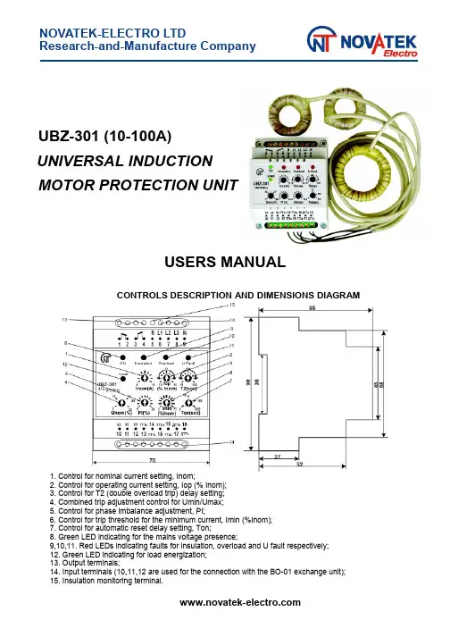
NOVATEK-ELECTRO LTDResearch-and-Manufacture CompanyUBZ-301 (10-100A)UNIVERSAL INDUCTIONMOTOR PROTECTION UNITUSERS MANUALCONTROLS DESCRIPTION AND DIMENSIONS DIAGRAM 4151. Control for nominal current setting, Inom;2. Control for operating current setting, Iop (% Inom);3. Control for T2 (double overload trip) delay setting;4. Combined trip adjustment control for Umin/Umax;5. Control for phase imbalance adjustment, PI;6. Control for trip threshold for the minimum current, Imin (%Inom);7. Control for automatic reset delay setting, Ton;8. Green LED indicating for the mains voltage presence;9,10,11. Red LEDs indicating faults for insulation, overload and U fault respectively;12. Green LED indicating for load energization;13. Output terminals;14. Input terminals (10,11,12 are used for the connection with the BO-01 exchange unit);15. Insulation monitoring terminal.1 APPLICATIONSThe UBZ-301(10-100A)universal induction motor protection unit is designed for the continuous monitoring of the mains voltage parameters and for RMS phase/line currents of 3-Phase AC 380V/50Hz electrical equipment monitoring, primarily, of induction motors whose power is from 5kW up to 50 kW, isolated neutral system included.The unit provides full and effective protection of electrical equipment by a magnetic starter (contactor) coil control.The unit isolates electrical equipment from the running system and/or disables its start. This is performed in the following cases:1. when the mains voltage is of poor quality (unallowable voltage jumps, phase loss, incorrect phase sequence and phase «coincidence», phase/line voltage imbalance);2. when mechanical overloads (symmetrical phase/line current overload) take place. The unit performs overload protection with a dependent time delay;3. when phase/line current asymmetrical overloads induced by faults inside the motor occur. The unit performs protection from phase current imbalance and further disables an automatic reset;4. when phase current asymmetry without overload occurs that is induced by the insulation fault inside the motor and/or the power cable;5.when motor load is lost(«dry stroke»for pumps).The unit provides the minimum start and/or operating current protection;6. when insulation level to frame is abnormally low. The unit performs insulation level test before start and if the insulation is poor the start is disabled.7.when stator winding ground-to-fault occurs during operation. The unit performs the ground leakage current protection.The UBZ-301 (10-100A) provides:•a simple and accurate electromotor nominal current setting by nominal current standard scale;•the electromotor operating current setting that differs from standard values;•overload tripping with a dependent time delay (the current-time characteristic curve is plotted for a conventionally cold motor). The motor heat balance differential equation is being solved in the operation process. This approach enables to take account of the preceding electromotor status and to make a decision on heat overload presence with the maximum validity. This method also permits to allow for a motor start heating and to restrict (at the customer’s option) amount of starts per unit time;•shift of current-time characteristic curve along the current-axis and along time-axis as well;•setting of trip thresholds for the minimum/the maximum voltage,line voltage&phase current imbalance, and also for automatic reset delay at the personal customer’s discretion;•fault type indication, the mains voltage presence indication, current range indication the unit is adjusted to, and load energization indication;•the data exchange and transfer to the local computer network according to the RS-485 MODBUS record through the BO-01 exchange unit (BO-01 is supplied on order).2 DESCRIPTIONThe unit is a microprocessor-based digital device that provides a high degree of reliability and accuracy. The unit doesn’t need any auxiliary supply because it retrieves it's energy demand out of the measurement signal: it’s self-powered by the voltage to be monitored. Simultaneous isolated independent monitoring for the mains voltage and phase currents permits to detect the type of occurring fault and to provide a different decision-making logic for each fault type. When the mains voltage faults occur the unit performs automatic load reset on return voltage parameters to normal operating conditions. If a fault is induced by abnormal condition inside the motor(phase current imbalance at the symmetrical mains voltage,leakage current presence etc.) restart is disabled.The unit is stocked with three toroidal current transducers. Two of them are the phase/line current transducers (TT1, TT2), power phase cables are pulled through them. The third transducer is the differential current transducer(DCT)that has an enlarged diameter,because three power phase cables are pulled through it. By the 6, 7, 8, 9 terminals the unit is connected in parallel to the mains supply to be monitored. The unit output is provided with N.O. and N. C. contacts (the 1, 2, 3, 4 terminals). The output 3-4 terminals are connected in series with the starter coil power supply (with control circuit). The5terminal is designed to monitor the insulation level. The unit wiring diagram is shown below.When the unit trips the load is de-energized by a break in the magnetic starter coil power circuit through the N. C. 3-4 contacts.Table 1 - The 1-2-3-4 output contacts specificationMax. current for~ 250 V A. C.Max. powerMax sustained safevoltage ~Max. current for U = 30V D.C.Cosφ = 0.43A 2000VA 460V 3ACosφ = 1.05ANominal parameters and trip thresholds are set by front-panel screwdriver potentiometers.Nominal current setting. Nominal current is set by № 1 potentiometer. There are eleven positions of the potentiometer. Each position corresponds to the specific standard nominal current scale value (see below Table of Nominal Currents). Each position is characterized by the specific number of blinks that the green «On» LED makes. To set the nominal current one needs to bring out potentiometer control arm to a corresponding position; when the unit is energized the number of blinks «On» LED must correspond to the Table below. One needs to take into account that there are «dead bands» between the positions where «On» LED glows without blinks and where the nominal current is indefinite.In order to set operating value which is different from the nominal one that is specified in the nominal current table, it’s recommended the № 1 potentiometer to set to the position corresponding to the nearest value from the nominal current scale, and by the № 2 potentiometer one can increase or decrease the necessary value in % from the set value.Table 2 - Nominal current tablePotentiometer №1 devisionsNom. current, АGreen LED «On» blink1101bl.- pause 212,52bl.- pause 3163bl.- pause 4204bl.- pause 5255bl.- pause 6326bl.- pause 7407bl.- pause 8508bl.- pause 9639bl.- pause 108010bl.- pause 1110011bl.- pauseNOTE S:1.Continuous green «On» LED glow means that the potentiometer is set in «dead band». One needs to set the potentiometer so as the green LED blinked and the number of blinks corresponded to the set nominal current.2.Nominal currents setting is to be performed correcting for load connections (Wye/Delta), according to ratings of engine.Controls and adjustmentsThe unit has seven independent controls. For user’s convenience screwdriver slots of adjusting potentiometers are brought out to the unit front panel.•№1 – «Inom» - nominal current setting; there are eleven positions and each position corresponds to the specific current from the nominal currents table;•№2 – «Iop» - operating current; it is set in ± 15 percent of nominal current, it has ten scale marks;•№3 – «T2» - overload trip delay when there is double overload for operating current set; in the central position T2 ≈ 58-60 seconds The minimum time delay is 10 seconds, the maximum time delay is 100 seconds. The control shifts current-time characteristic dependence along time axis;•№4 – «Unom(%)» - combined control for Umax/Umin threshold in percent of the nominal voltage; according to this setting before the load energization the unit is checking the mains voltage level and, depending on its value, permits or forbids the load energization; after the load has been energized the voltage monitoring is going on but the load de-energization decision is made for currents;•№5 – «PI%» - trip threshold control for line voltage imbalance and RMS phase current imbalance; it has ten scale marks. The parameter is calculated as the difference between the maximum and the minimum values, in percent of the maximum value. If current imbalance percentage is twice as much as voltage imbalance percentage then it’s supposed that the imbalance is induced by fault conditions inside the motor. The automatic reset is forbidden and the unit is disabled;•№6 – «Imin» - trip threshold control for the minimum operating current, in percent of operating current set. It has ten scale marks from 0% to 75%: in «0» position this control is off;•№7 – «Ton» - automatic reset delay, it is within 0 – 600 seconds range; the scale is logarithmic.Indication•the green «ON» LED indicates that voltage exists in the mains. In the blink mode of glow the blink number between pauses corresponds to the specific nominal current from the nominal current table; there is a continuous glow in a «dead band». One needs to set a nominal current in the blink mode of operation;•the green «Load» LED indicates that the load is energized (the 3-4 terminals are closed);•the red «Insulation» LED lights up with continuous glow before the start if the stator/ power cable winding insulation level is abnormally low (less than 500 kOhms), and also during operation when there is a tripping for differential current; the unit is disabled;•the red «U Fault» LED glows when the mains voltage fault has occurred. The blink mode of operation switches on when there is undervoltage/overvoltage, phase imbalance for the mains voltage, voltage is not present on all three phases;•incorrect phase sequence or phase coincidence induces the mode of operation when all three red LEDs are blinking in turn;•the red «Overload» LED blinks when the average phase current exceeds the nominal one. After the unit has tripped for overload this LED comes to glow during 0.9 AR (automatic reset) delay.4 TECHNICAL BRIEFNominal line voltage, V380Mains frequency, Hz45-55Nominal current range in UBZ-301 10-100, А10-100Operating current setting range, % of nominal±15Double overload delay adjustment range, sec10-100Voltage threshold adjustment range, % of nominal±(5-20)Phase imbalance adjustment range, %5-20Trip threshold adjustment range for the minimum current, % of nominal0-75Automatic reset delay adjustment range ( Тon), sec0-600First energization load delay when Тon= 0, sec2-3Trip delay for current overload According to current-time characteristic curveTrip delay for voltage fault, sec2Trip delay for current fault (overload excluded), sec2 Fixed trip point for leakage current, А 1.0 Insulation resistance threshold, kОhms500±20 Voltage hysteresis, V10/17 Heat hysteresis, % of stored-up heat after load de-energization33Trip threshold accuracy for current, % of nominal current, not more than2-3 Trip threshold accuracy for voltage, V, not more than3 Phase imbalance accuracy, %, not more than 1.5 Operating voltage range, % of nominal one50-150 Power consumption (under load), VA, not more than 3.0 Maximum switched current of output contacts, A5 Output contact life:- under 5A load , operations, no less than - under 1A load , operations, no less than 100 000 1 000 000Enclosure:- apparatus- terminal block IP40 IP20Operating temperature range, °C from -35 to +55 Storage temperature, °C from -45 to +70 Weight, kg, not more than0.200Case dimensions 4 modules of S-typeMounting standard 35 mm DIN-railMounting position arbitrary5 OPERATION1. After supply voltage has been applied to the unit and before the output relay is energized the unit checks:•a stator winding insulation level to frame. If insulation resistance is below 500±20 kOhms, the load is not energized. The red «Insulation» LED glows;•the mains voltage quality,i.e.if voltage is present on all three phases,if the mains voltage is symmetrical, what the RMS line voltage value is like. When any of inhibit factors is present, the load is not energized, the red «U Fault» LED blinks;•a correct phase sequence, and phase «non-coincidence». When any of inhibit factors is present, the load is not energized, all red LEDs are blinking in turn; If all the parameters are normal, the outlet relay will be energized after Ton delay has expired (the 3-4 contacts are being closed and the 1-2 contacts are being opened) - the green «Load» LED glows. If load currents are absent (there are no less 2% of nominal one) the reason is that the load is de-energized. Voltage monitoring and insulation level is going. Output relay of unit is de-energized if inhibit factors are present in pause without currents;2. After the load is energized the unit performs voltage and current monitoring. The decision on load de-energization is made according to the following factors:•RMS current exceeds the nominal (operating) current (set by №№ 1, 2, 3 potentiometers); if there is current overload without heat overload the red «Overload» LED blinks but the load is not de-energized. If current overload induces heat overload the load is de-energized. The red «Overload»LED glows and is ON during 0.9Ton. The automatic reset is permitted;•current imbalance (set by №5 potentiometer) is twice exceeds the mains voltage imbalance; the load is de-energized, all red LEDs glow, the unit is disabled, the automatic reset is forbidden. To enable the unit one needs to remove supply voltage from the unit. It’s supposed that this type of fault is induced by abnormal conditions inside the motor;•current imbalance (set by №5 potentiometer) is less than twice exceeds voltage imbalance; the load is de-energized, the red «U Fault» LED glows, the automatic reset is permitted;•current imbalance (set by №5 potentiometer) is less than voltage imbalance; the load is de-energized, the red «U Fault» LED blinks, the automatic reset is permitted;•the average current value is less than Imin (set by №6 potentiometer); the load is de-energized, all red LEDs blink simultaneously, the unit is disabled, the automatic reset is forbidden. To enable the unit one needs to remove the supply voltage from the unit.Electromotor protection against heat overloadThe electromotor heat balance equation is being solved as the work advances. It’s supposed that:•the motor was cold before start;•during operation the motor releases the heat which is proportional to the current square;•after the stop the motor cools down exponentially.Below is the current-time characteristic curve with different T2 values (set by №3 potentiometer), where:•I/In – current ratio relative to the nominal current;•T/T2 -- actual trip delay relative to T2 (set by № 3 potentiometer).Current-time characteristic dependenceThe current-time characteristic dependence shown in the tables below is given for the standard recommended T2 value (the №3 potentiometer middle position corresponds to 60 seconds when double overload occurs):I/Inom 1.1 1.2 1.4 1.72 2.73456781015Тsec36524714888.66036.424.613.58.5 5.9 4.3 3.3 2.10.9After the load has been de-energized owing to the heat overload it will automatically be energized again:•according to heat hysteresis if time delay Ton=0, i. e. the motor must cool down 33% of the stored up heat;•according time delay Ton (№ 7 potentiometer) if Ton isn’t equal 0.By suitable selection of different Ton values, heat hysteresis considered, one can reduce number of starts per time unit because in the intermittent cycle the unit stores heat quantity released at the start of the motor.6 PRELIMINARY STARTING PROCEDURE AND SERVICE MANUALThe unit produced is completely ready for operation and needs no special pre-starting procedure measures. Owing to digital technology all the unit settings are aligned quite accurate, so no control devices are needed to adjust them. Use of the unit according to specifications above and the present service manual, continuous work included, relieves of preventive maintenance during service life. To put the unit in operation one must follow operating instructions given below:1.To set nominal (operating) current, trip thresholds, trip delays and reset delay by potentiometer's contact arms.2.To connect the unit according to the wire diagram given below:•by the 6(L1), 7(L2), 8(L3), 9(N) terminals the unit is connected in parallel to the mains supply to be monitored;•two current transducers (each one of them is put on two power phase wires that carry the load) are connected to the 13, 14, 15, 16 terminals; in connecting one has to consider the transducers grading;1st transducer– the beginning – the 13 terminal, the end – the 14 terminal;2nd transducer– the beginning – the 15 terminal, the end – the 15 terminal;•a differential current transducer that is put on the three power phase wires must be connected to the 17, 18 terminals (the connection grading is unimportant);•the 5 insulation monitoring terminal is connected to one of the MS output contacts;•output contacts (the 3-4 terminals) are connected to the MS coil power supply circuit (control circuit);•the BO-01 exhange and date transfer unit is connected to the 10, 11, 12 terminals (this unit is supplied on order).3.To apply a voltage to the unit. The correct setting of nominal current is checked by the number of blinks that the green LED makes. After Ton has expired (if there are no factors that can forbid energizing) the output relay of the unit is energized. If Ton=0, the first energizing will occur after 2-3 sec delay has expired.NOTE - The unit must be connected subject to the safety regulations. To set settings is recommended in «off» state. To set settings alive is permitted in the test conditions subject to the safety regulations.ATTENTION!If immediately after the load has been energized the unit de-energizes it and disables it for current imbalance,the incorrect polarity of the current transducers TT1or TT2 connection may be a reason. Then it’s recommended to change one of the transducers connection by reversing the places“the beginning-the end”of the13-16terminals.If the effect pointed above repeats when the load is re-energized it means that the transducers were connected correctly and the imbalance arose from EM and/or power cable fault.NOTES:1 Transducers are mounted by plastic clamps (they are component parts of supplies).2 The phase wires which are passing through the differential transducer to try to symmetrize in the centerof the transducer.WIRING DIAGRAMDT–differential current transducer (differential current transformer);CT1,CT2–current--transducers;BO-01– exchange and date transfer unit (on order)NOTE:1 “START”-button and “STOP”-button can be connected to MSC power supply circuit if necessary;2 The 220V MSC connection is shown here. The 380V MSC power supply circuit is analogous, coil power is applied from different phases through the 3-4 contacts;3 If BO-01 is absent the 10, 11, 12 terminals are not used.7 STORAGE AND SHIPPING CONDITIONSThe unit in manufacturer package should be stored in enclosed rooms at –45 to +70 °C and exposed to no more than 80% of relative humidity when there are no fumes in the air that exert a deleterious effect on package and the unit material. The Buyer must provide the protection of the unit against mechanical damages in transit.8 WARRANTYNovatek-Electro LTD. Company warrants a trouble-free operation of the UBZ-301 (10-100A) unit manufactured by it within 36 months from the date of sale, provided:•the proper installation;•the safety of the inspection quality control department seal;•the integrity of the case, no traces of an opening, cracks, spalls etc.。
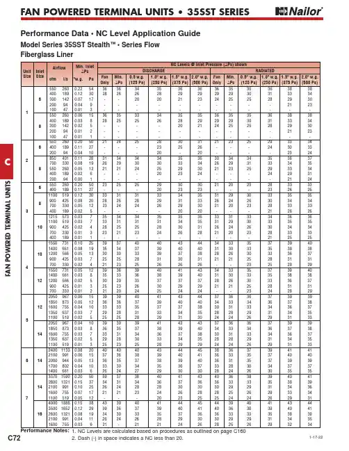
F A N P O W E R E D T E R M I N A L U N I T SC72FAN POWERED TERMINAL UNITS • 35SST SERIESPerformance Data • NC Level Application GuideModel Series 35SST Stealth ™ • Series Flow Fiberglass Liner2. Dash (-) in space indicates a NC less than 20.1-17-22FAN POWERED TERMINAL UNITSCFAN POWERED TERMINAL UNITS • 35SST SERIESPerformance Data • Discharge Sound Power LevelsModel Series 35SST Stealth ™ • Series Flow Fiberglass LinerFAN POWERED TERMINAL UNITSCC75FAN POWERED TERMINAL UNITS • 35SST SERIES∑Motor = ECM.* Primary air valve is closed and therefore primary cfm is zero.Performance Data • AHRI Certification and Performance NotesModel Series 35SST Stealth ™ • Series Flow • AHRI Certification Rating PointsFiberglass LinerRatings are certified in accordance with AHRI Standards.Performance Notes for Sound Power Levels:1. Discharge (external) static pressure is 0.25" w.g. (63 Pa) in all cases, which is the difference (∆Ps) in static pressure from terminal discharge to the room.Discharge Sound Power Levels (SWL) now include duct end reflection energy as part of the standard rating. Including the duct end correction provides sound power levels that would normally be transmitted into an acoustically, non-reflective duct. The effect of including the energy correction to the discharge SWL, is higher sound power levels when compared to previous AHRI certified data. For more information on duct end reflection calculations see AHRI Standard 880.2. Radiated sound power is the breakout noise transmitted through the unit casing walls.3. Sound power levels are in decibels, dB re 10-12 watts.4. All sound data listed by octave bands is raw data without any corrections for room absorption or duct attenuation. Dash (-) in space indicates sound power level is less than 20 dB or equal to background.5. Min. inlet ∆Ps is the minimum operating pressure of the primary air valve section.6. Asterisk (*) in space indicates that the minimum inlet static pressure requirement is greater than 0.5" w.g. (125 Pa) at rated airflow.7. Data derived from independent tests conducted in accordance with ANSI / ASHRAE Standard 130 and AHRIStandard 880.F A N P O W E R E D T E R M I N A L U N I T SFAN POWERED TERMINAL UNITS • 35SST SERIESPerformance Data • Radiated Sound Power LevelsModel Series 35SST Stealth ™ • Series Flow Fiberglass LinerFAN POWERED TERMINAL UNITSCC75FAN POWERED TERMINAL UNITS • 35SST SERIES∑Motor = ECM.* Primary air valve is closed and therefore primary cfm is zero.Performance Data • AHRI Certification and Performance NotesModel Series 35SST Stealth ™ • Series Flow • AHRI Certification Rating PointsFiberglass LinerRatings are certified in accordance with AHRI Standards.Performance Notes for Sound Power Levels:1. Discharge (external) static pressure is 0.25" w.g. (63 Pa) in all cases, which is the difference (∆Ps) in static pressure from terminal discharge to the room.Discharge Sound Power Levels (SWL) now include duct end reflection energy as part of the standard rating. Including the duct end correction provides sound power levels that would normally be transmitted into an acoustically, non-reflective duct. The effect of including the energy correction to the discharge SWL, is higher sound power levels when compared to previous AHRI certified data. For more information on duct end reflection calculations see AHRI Standard 880.2. Radiated sound power is the breakout noise transmitted through the unit casing walls.3. Sound power levels are in decibels, dB re 10-12 watts.4. All sound data listed by octave bands is raw data without any corrections for room absorption or duct attenuation. Dash (-) in space indicates sound power level is less than 20 dB or equal to background.5. Min. inlet ∆Ps is the minimum operating pressure of the primary air valve section.6. Asterisk (*) in space indicates that the minimum inlet static pressure requirement is greater than 0.5" w.g. (125 Pa) at rated airflow.7. Data derived from independent tests conducted in accordance with ANSI / ASHRAE Standard 130 and AHRIStandard 880.FAN POWERED TERMINAL UNITSCC75FAN POWERED TERMINAL UNITS • 35SST SERIES∑Motor = ECM.* Primary air valve is closed and therefore primary cfm is zero.Performance Data • AHRI Certification and Performance NotesModel Series 35SST Stealth ™ • Series Flow • AHRI Certification Rating PointsFiberglass LinerRatings are certified in accordance with AHRI Standards.Performance Notes for Sound Power Levels:1. Discharge (external) static pressure is 0.25" w.g. (63 Pa) in all cases, which is the difference (∆Ps) in static pressure from terminal discharge to the room.Discharge Sound Power Levels (SWL) now include duct end reflection energy as part of the standard rating. Including the duct end correction provides sound power levels that would normally be transmitted into an acoustically, non-reflective duct. The effect of including the energy correction to the discharge SWL, is higher sound power levels when compared to previous AHRI certified data. For more information on duct end reflection calculations see AHRI Standard 880.2. Radiated sound power is the breakout noise transmitted through the unit casing walls.3. Sound power levels are in decibels, dB re 10-12 watts.4. All sound data listed by octave bands is raw data without any corrections for room absorption or duct attenuation. Dash (-) in space indicates sound power level is less than 20 dB or equal to background.5. Min. inlet ∆Ps is the minimum operating pressure of the primary air valve section.6. Asterisk (*) in space indicates that the minimum inlet static pressure requirement is greater than 0.5" w.g. (125 Pa) at rated airflow.7. Data derived from independent tests conducted in accordance with ANSI / ASHRAE Standard 130 and AHRIStandard 880.。
Valid from September 2011 (current)PDF EditionSummary and Status Choices (top of page)Changes Summary of changes and current document status September 2011 RevNote: "Summary of changes" replaces "Amendments and Corrections" as of October 2010.Service Specifications Choices (top of page)DNV-DSS-314 Verification of Hydrocarbon Refining and Petrochemical Facilities October 2010 DNV-DSS-315 Verification of Onshore LNG and Gas Facilities October 2010Offshore Service Specifications Choices (top of page)DNV-OSS-101 Rules for Classification of Offshore Drilling and Support Units April 2011DNV-OSS-102 Rules for Classification of Floating Production, Storage and Loading Units April 2011 DNV-OSS-103 Rules for Classification of LNG/LPG Floating Production and Storage Units or Installations June 2011DNV-OSS-121 Classification Based on Performance Criteria Determined from Risk Assessment Methodology October 2008DNV-OSS-201 Verification for Compliance with Norwegian Shelf Regulations April 2010DNV-OSS-202 Verification for Compliance with UK Shelf Regulations April 2011DNV-OSS-300 Risk Based Verification April 2004DNV-OSS-301 Certification and Verification of Pipelines October 2000DNV-OSS-302 Offshore Riser Systems October 2010DNV-OSS-304 Risk Based Verification of Offshore Structures October 2006DNV-OSS-305 Rules for Certification and Verification of Diving Systems October 2010DNV-OSS-306 Verification of Subsea Facilities June 2004DNV-OSS-307 Verification of Process Facilities June 2004DNV-OSS-308 Verification of Lifting Appliances for the Oil and Gas Industry October 2010DNV-OSS-312 Certification of Tidal and Wave Energy Converters October 2008DNV-OSS-313 Pipe Mill and Coating Yard - Qualification April 2009DNV-OSS-401 Technology Qualification Management October 2010Standards Choices (top of page)DNV-DS-J102 Design and Manufacture of Wind Turbine Blades, Offshore and Onshore Wind Turbines November 2010Offshore Standards Choices (top of page)DNV-OS-A101 Safety Principles and Arrangements April 2011DNV-OS-B101 Metallic Materials April 2009DNV-OS-C101 Design of Offshore Steel Structures, General (LRFD Method) April 2011DNV-OS-C102 Structural Design of Offshore Ships April 2011DNV-OS-C103 Structural Design of Column Stabilised Units (LRFD Method) October 2009DNV-OS-C104 Structural Design of Self-Elevating Units (LRFD Method) April 2009DNV-OS-C105 Structural Design of TLPs (LRFD Method) April 2011DNV-OS-C106 Structural Design of Deep Draught Floating Units/Spars (LRFD and WSD Method) October 2009DNV-OS-C107 Structural Design of Ship-shaped Drilling and Well Service Units October 2009 DNV-OS-C201 Structural Design of Offshore Units (WSD Method) April 2011DNV-OS-C301 Stability and Watertight Integrity April 2011DNV-OS-C401 Fabrication and Testing of Offshore Structures October 2010DNV-OS-C501 Composite Components October 2010DNV-OS-C502 Offshore Concrete Structures October 2010DNV-OS-C503 Concrete LNG Terminal Structures and Containment Systems October 2010DNV-OS-D101 Marine and Machinery Systems and Equipment October 2010DNV-OS-D201 Electrical Installations April 2011DNV-OS-D202 Automation, Safety, and Telecommunication Systems October 2008DNV-OS-D203 Integrated Software-Dependent System (ISDS) June 2011DNV-OS-D301 Fire Protection October 2009DNV-OS-E101 Drilling Plant October 2009DNV-OS-E201 Oil and Gas Processing Systems October 2010DNV-OS-E301 Position Mooring October 2010DNV-OS-E302 Offshore Mooring Chain October 2009DNV-OS-E303 Offshore Mooring Fibre Ropes October 2010DNV-OS-E304 Offshore Mooring Steel Wire Ropes October 2009DNV-OS-E401 Helicopter Decks April 2011DNV-OS-E402 Offshore Standard for Diving Systems October 2010DNV-OS-E403 Offshore Loading Buoys October 2008DNV-OS-E406 Design of Free Fall Lifeboats April 2010DNV-OS-F101 Submarine Pipeline Systems October 2010DNV-OS-F201 Dynamic Risers October 2010DNV-OS-J101 Design of Offshore Wind Turbine Structures September 2011 RevDNV-OS-J201 Offshore Substations for Wind Farms October 2009DNV-OS-J301 Standard for Classification of Wind Turbine Installation Units April 2011Recommended Practices Choices (top of page)DNV-RP-A201 Plan Approval Documentation Types – Definitions April 2011DNV-RP-A203 Qualification of New Technology July 2011DNV-RP-A204 Quality Survey Plan (QSP) for Offshore Class New-building Surveys September 2011 NewDNV-RP-B101 Corrosion Protection of Floating Production and Storage Units April 2007DNV-RP-B401 Cathodic Protection Design April 2011DNV-RP-C101 Allowable Thickness Diminution for Hull Structure of Offshore Ships April 2007 DNV-RP-C102 Structural Design of Offshore Ships February 2002DNV-RP-C103 Column-Stabilised Units October 2010DNV-RP-C104 Self-elevating Units April 2011DNV-RP-C201 Buckling Strength of Plated Structures October 2010DNV-RP-C202 Buckling Strength of Shells October 2010DNV-RP-C203 Fatigue Design of Offshore Steel Structures April 2010DNV-RP-C204 Design against Accidental Loads October 2010DNV-RP-C205 Environmental Conditions and Environmental Loads October 2010DNV-RP-C206 Fatigue Methodology of Offshore Ships October 2010DNV-RP-C207 Statistical Representation of Soil Data October 2010DNV-RP-D101 Structural Analysis of Piping Systems October 2008DNV-RP-D201 Integrated Software Dependent Systems October 2009DNV-RP-E101 Recertification of Well Control Equipment October 2008DNV-RP-E102 Recertification of Blowout Preventers and Well Control Equipment for the US Outer Continental Shelf June 2010DNV-RP-E301 Design and Installation of Fluke Anchors in Clay May 2000DNV-RP-E302 Design And Installation of Plate Anchors in Clay December 2002DNV-RP-E303 Geotechnical Design and Installation of Suction Anchors in Clay October 2005DNV-RP-E304 Damage Assessment of Fibre Ropes for Offshore Mooring April 2005DNV-RP-E307 Dynamic Positioning Systems - Operation Guidance January 2011DNV-RP-E401 Survey of Diving Systems April 2007DNV-RP-E402 Naval Rescue Submersibles October 2010DNV-RP-E403 Hyperbaric Evacuation Systems October 2010DNV-RP-F101 Corroded Pipelines October 2010DNV-RP-F102 Pipeline Field Joint Coating and Field Repair of Linepipe Coating May 2011DNV-RP-F103 Cathodic Protection of Submarine Pipelines by Galvanic Anodes October 2010 DNV-RP-F105 Free Spanning Pipelines February 2006DNV-RP-F106 Factory Applied External Pipeline Coatings for Corrosion Control May 2011DNV-RP-F107 Risk Assessment of Pipeline Protection October 2010DNV-RP-F108 Fracture Control for Pipeline Installation Methods Introducing Cyclic Plastic Strain January 2006DNV-RP-F109 On-Bottom Stability Design of Submarine Pipelines October 2010DNV-RP-F110 Global Buckling of Submarine Pipelines Structural Design due to High Temperature/High Pressure October 2007DNV-RP-F111 Interference Between Trawl Gear and Pipelines October 2010DNV-RP-F112 Design of Duplex Stainless Steel Subsea Equipment Exposed to Cathodic Protection October 2008DNV-RP-F113 Pipeline Subsea Repair October 2007DNV-RP-F116 Integrity Management of Submarine Pipeline Systems October 2009DNV-RP-F118 Pipe Girth Weld AUT System Qualification and Project Specific Procedure Validation October 2010DNV-RP-F201 Design of Titanium Risers October 2002DNV-RP-F202 Composite Risers October 2010DNV-RP-F203 Riser Interference April 2009DNV-RP-F204 Riser Fatigue October 2010DNV-RP-F205 Global Performance Analysis of Deepwater Floating Structures October 2010DNV-RP-F206 Riser Integrity Management April 2008DNV-RP-F301 Subsea Separator Structural Design April 2007DNV-RP-F302 Selection and use of Subsea Leak Detection Systems April 2010DNV-RP-G101 Risk Based Inspection of Offshore Topsides Static Mechanical Equipment October2010DNV-RP-G103 Non-Intrusive Inspection January 2011DNV-RP-H101 Risk Management in Marine and Subsea Operations January 2003DNV-RP-H102 Marine Operations during Removal of Offshore Installations April 2004DNV-RP-H103 Modelling and Analysis of Marine Operations April 2011DNV-RP-H104 Ballast, Stability, and Watertight Integrity - Planning and Operating Guidance September 2011 NewDNV-RP-J101 Use of Remote Sensing for Wind Energy Assessments April 2011DNV-RP-J201 Qualification Procedures for CO2 Capture Technology April 2010DNV-RP-J202 Design and Operation of CO2 Pipelines April 2010DNV-RP-O401 Safety and Reliability of Subsea Systems April 1985DNV-RP-O501 Erosive Wear in Piping Systems November 2007[View archive by document]。
S I-1404p r o v i d e s a c o m p r e h e n s i v e3r d L i n e/D e p o t L e v e l t e s tM K1Comprehensive Mode S (level 4) andinterrogator simulationAccurate measurement of transponderpulse parametersConfiguration memory stores 5completeconfigurationsExtended squitter DF17capabilitycrypto simulation plus external crypto interfaceBuilt-in self testLCD display with adjustable back-lightIEEE-488.2GPIB & RS-232interfaceTwo-year limited warrantyAeroflex is a leader in the design, manufacture and marketing of Avionics test systems.SI-1404The SI-1404 is a Depot Level/3rd Line test accessory, used in con-junction with the ATC-1400A Ting IFF transponders in a maintenance or production environment. The SI-1404/ATC-1400A may also be utilized by OEMs to perform most of the MOP (Minimum Operational Performance) tests defined in RTCA/DO-181A, required in the Mode S transponder certification process.The SI-1404 and ATC-1400A form a comprehensive SSR ground station simulator capable of parametric and protocol testing MK10A (Mode 1, 2, 3/A, C), MK12 (Mode 1, 2, 3/A, 4, C) and MK12/Mode S transponders.OPERATIONDisplayOperation of the SI-1404 is via a menu system displayed on a 40 col-umn x 4 row alphanumeric LCD display. The display has an adjustable illumination backlight, which provides viewable screens under all ambient lighting conditions.KeypadMenu selection and data entry is provided via a 4 x 5 main key pad, four directional cursor keys and a slew knob. Dedicated keys are pro-vided for commonly used functions.G E N E R A LCalibration Interval1 yearAC Supply100 to 120 VAC, 220 to 240 VAC, 50 Hz to 60 Hz, ≤+10% of the nominal voltage48 W maximum (180 W maximum with ATC-1400A)AC OutputLine output, fused at 3 amps and switchedENVIRONMENTALTemperature5° to 40°CRelative Humidity≤ 80% for temperature up to 31°C decreasing linearty to 50% at 40°C (Non-condensing)Altitude≤ 4000 m (13,124 ft.)Electromagnetic CompatibilityComplies with the limits in the following standards:EN55011 Class BEN50082-1SafetyComplies with EN61010-1:1993 for class 1 portable equipment and is for use in a pollution degree 2 environment. The instrument is designed to operate from an installation category 1 or 2 supply. Dimensions425 mm wide x 89 mm high x 467 mm deep16.8 in. wide x 3.5 in. high x 18.4 in. deepWeight6.75 kg (15 Ibs.)V E R S I O N S A N D A C C E S S O R I E SWhen ordering please quote the full ordering number information.OrderingNumbers Versions1404-110SI-1404 Modes S & 4 T ransponder with MLD,110 VAC Certificate of Calibration1404-220SI-1404, 220 VAC OperationAll Aeroflex Avionics products delivered with Factory Certificate Of Calibration EXPORT CONTROL:This product is controlled for export under the International Traffic in Arms Regulations (ITAR). A license from the U.S. Department of State is required prior to the export of this product from the United States. EXPORT WARNING:Aeroflex’s military products are controlled for export under the International Traffic in Arms Regulations (ITAR) and may not be sold or proposed or offered for sale to certain countries including: Belarus, Burma, China, Cuba, Haiti, Iran, Liberia, Libya, North Korea, Somalia, Syria, Sudan, and Vietnam. See ITAR 126.1 for complete information.For the very latest specifications visit 。
1IEC Appliance Inlet C20 with Circuit Breaker TA35 1-poleSee below:Approvals and CompliancesC2070° CDescription- Panel mount :Snap-in version from front side - 2 Functions :Appliance Inlet , Protection class I , Circuit breaker type TA35 , 1-pole - Quick connect terminals 6.3 x 0.8 mmCharacteristics- Unwired- Switch non-illuminated or illuminated- Suitable for use in equipment according to IEC/UL 60950Other versions on request- Pre-wired version- Quick connect terminals 4.8 x 0.8 mm - Protection class II, 70°CReferences Alternative: version for 10 A (15 A) 6135 Substitute for type 1624-KWeblinkspdf datasheet , html-datasheet , General Product Information , Distributor-Stock-Check , Accessories , Detailed request for product , Landing PageNewly available variants corresponding to V-Lock mating cordset. The connector is equipped with a notch intended for use with the latching cordset. The cord latching system prevents against accidental removal of the cordset.T echnical DataRatings IEC16 A / 250 VAC; 50 Hz Ratings UL/CSA 20 A / 250 VAC; 60 Hz Dielectric Strength> 2.5 kVAC between L-N > 3 kVAC between L/N-PE (1 min/50 Hz)Allowable Operation Tempe-rature-25 °C to 60 °CIP-Protection from front side IP 40 acc. to IEC 60529Insulation cover Suitable for appliances with protection class I acc. to IEC 61140TerminalQuick connect terminals 6.3 x 0.8 mm Panel Thickness S Snap-in: 1.5/2/2.5 mmMaterial: HousingThermoplastic, black, UL 94V-0appliance inlet/-outletC20 acc. to IEC 60320-1,UL 60320-1, CSA C22.2 no. 60320-1 (for cold conditions) pin-temperature 70 °C, 16 A, Protection Class ICircuit BreakersAcc. IEC/EN 60934, UL 1077, CSA 22.2 no. 2351-pole rocker switch, illuminated or non-illuminated.Conditional short circuit Inc: 2000 AApprovals and CompliancesDetailed information on product approvals, code requirements, usage instructions and detailed test conditions can be looked up in Details about ApprovalsApprovalsThe approval mark is used by the testing authorities to certify compliance with the safety requirements placed on electronic products. Approval Reference T ype: 6136Approval LogoCertificates Certification Body DescriptionVDE Approvals VDE Certificate Number: 40025196UL Approvals ULUL File Number: E96454CQC ApprovalsCQCCCC Certificate Number: 2015180204000153Product standardsProduct standards that are referencedOrganization Design StandardDescriptionDesigned according to IEC 60320-1Appliance couplers for household and similar general purposesDesigned according to UL 60320-1Standard for Attachment Plugs and ReceptaclesDesigned according to CSA C22.2 no. 60320-1General Use Receptacles, Attachment Plugs, and Similar Wiring Devices Application standardsApplication standards where the product can be usedOrganization Design StandardDescriptionDesigned for applications acc.IEC/UL 60950IEC 60950-1 includes the basic requirements for the safety of informationtechnology equipment.CompliancesThe product complies with following Guide LinesIdentification Details Initiator DescriptionCE declaration of conformity SCHURTER AG The CE marking declares that the product complies with the applicablerequirements laid down in the harmonisation of Community legislation onits affixing in accordance with EU Regulation 765/2008.RoHS SCHURTER AG EU Directive RoHS 2011/65/EUChina RoHS SCHURTER AG The law SJ / T 11363-2006 (China RoHS) has been in force since 1 March2007. It is similar to the EU directive RoHS.REACH SCHURTER AG On 1 June 2007, Regulation (EC) No 1907/2006 on the Registration,Evaluation, Authorization and Restriction of Chemicals 1 (abbreviated as"REACH") entered into force.MicrositeV-Lock SCHURTER AG V-Lock system are based on a matching plug-dose combination. Theconnector is equipped with a notch intended for use with the latchingcordset. The cord latching system prevents against accidental removal ofthe cordset.Dimensions [mm]23Diagramsnon-illuminatedPE 1)2)1) Line 2) Loadilluminated (connection N' to L)N PE 1)2)1) Line 2) Load45Technical data (continued)Circuit breakerTripping characteristics I n < 3 ATripping characteristics I n > 3 ... 20 AE ect of ambient temperatureThe unit is calibrated for an ambient temperature of +23 °C. Todetermine the rated current for lower or higher ambient temperature, use a correction factor from the table below.* AmbientCorrection factor temperature [°C] –25 0.79–20 0.81 0 0.90 +23 1.00 +40 1.03 +50 1.04+601.06* Temperature must be measured at the rear of the breakernext to the terminals after equipment operating tempera-ture has been reached.Example:Rated current at +23 °C 10 A Ambient temperature +60 °C Correction factor1.06Chosen rated current at +60 °C ambient temperature:10 A x 1.06 = 10.6 AOrder code (Order example)Multiple of rated current[ x I n ]T r i p p i n g t i m e10'00060[ min ]1051302010'00060[ sec [ min ]10513020]Multiple of rated current[ x I n ]T r i p p i n g t i m eMounting1 Snap-in s = 1.0 mm2 Snap-in s = 1.5 mm3 Snap-in s = 2.0 mm4 Snap-in s = 2.5 mmCord Retention 0 Without 1 V-LockTerminal PE1 Quick connect terminals 6.3 x 0.8 mm Terminal N1 Quick connect 6.3 x 0.8 mm Terminal L1 Quick connect 6.3 x 0.8 mm4 Wire connection to circuit breakerPackaging unit 15 Pcs Mating Outlets/ConnectorsCategory / DescriptionConnector Overview completeIEC Connector C19, Rewireable, Straight4795IEC Connector C19, Rewireable, Angled4790Connector further types to 6136Power Supply Cord Overview completeCord Sets 16 A, Europlug, 2.5 m, Connector IEC C19, H05VV-F3G1.5, black6004.0395Cord Sets 16 A, Interconnection, 1.0 m, Connector IEC C19, H05VV-F3G1.5, black6020.0392Cord Sets 16 A, Interconnection, 2.0 m, Connector IEC C19, H05VV-F3G1.5, black6020.0394Cord Sets 16 A, North America, 2.5 m, Connector IEC C19, SJT 3x14 AWG, black6009.5195Power Supply Cord further types to 6136Mating Outlets/Connectors shutteredPower Cord Overview completeOverview Power Cord with IEC Appliance Connector C19, V-Lock, straight VAC19KSPower Cord further types to 6136The specifications, descriptions and illustrations indicated in this document are based on currentinformation. All content is subject to modifications and amendments. Information furnished is believed19.9.2186。
Temperature Panel and Benchtop Meters1⁄8DIN Size with LCD DisplayModel BS6000ASingleThermocouple Input$495Model BS6050Single RTD Input$495Model BS6051Six-Channel RTD Selectable$595Specifications for DP5000A and BS6000 SeriesInputs:Thermocouples: J, K, T, E, N, R, S; RTD Pt100, 2-, 3-, or 4-wire, Alpha 0.00385,Thermistor: 2252 Ωat 25°C (77°F).Display: 4-digit, backlit LCD Accuracy:±0.15% of rdg + 0.2°C at orabove 0°C (+0.4°F) at or above 32°F)±1°C below 0°C (±2°F below 32°F)Resolution:0.1°to 999.9°; 1°above 1000°Temperature Coefficient:0.01% of rdg/°CCold Junction Compensation: 0.0075°C/°C (0.0135°F/°F)Ambient Temperature : 0 to 50°C (32 to 122°F)Storage Temperature:-40 to 50°C (-40 to 122°F)Humidity: 0 to 70% non-condensing Power : 110 Vac (standard),Optional 230 Vac or 9 to 30 Vac/dcM-101ߜEasy-to-Read Backlit LCD ߜ°C/°F Switchable ߜ0.1°/1°Auto Ranging ߜThermocouple Selectable by Rear Panel SwitchesߜFront Panel Splash-Proof (IP65)ߜCan Be Used with OS36, OS37, and OS38 Infrared Probes ߜOptional RS-232ߜBenchtop Portable Meters ߜRugged ABS Case ߜAvailable as Single- or Six-Input ModelsDimensions:DP5000A, DP5050, DP5060:96 x 48 x 120 mm (3.78 x 1.89 x 4.72")BS6000A, BS6050, BS6060:118 x 57 x 150 mm (4.65 x 2.24 x 5.90")BS6001A,BS6051, BS6061:148 x 67 x 190 mm (5.83 x 2.64 x 7.48")Weight:DP5000A, DP5050, BS5060: 255 kg (0.56 lb)BS6000A, BS6050, BS6060: 500 g (1.1 lb)BS6001A, BS6051, BS6061: 850 g (1.87 lb)The DP5000A and BS6000 series of temperature panel and benchtop meters are both highly versatile and accurate. Available in thermocouple and infrared inputs, thermistor and RTD versions with 0.1 degree resolution, auto ranging to 1 degree above 1000°. The thermocouple versions are switch selectable for one of six thermocouple types from the rear panel. The DP5000A series is micro-processor driven andfully self-calibrating, offering exceptional accuracy and long term stability. The backlit LCD is easy to read in any light conditions from dim to bright sunlight, or fluorescent lighting.To Order (Specify Model Number)Model No.Price DescriptionDP5000A $245T/C input panel meter with infrared sensor input*DP5050245RTD input panel meterDP5060245Thermistor input panel meterBS6000A*495Benchtop meter: 1 T/C and OS36, OS37 OS38 input BS6001A*595Benchtop meter: 6 T/C and OS36, OS37 OS38 inputs BS6050495Benchtop meter: 1 RTD input BS6051595Benchtop meter: 6 RTD inputBS6060495Benchtop meter: 1 thermistor input BS6061595Benchtop meter: 6 thermistor inputsMDP5000A Series$245ShownModel OS36-K-50 probe, $185See Section JShown smaller than actual sizeModel NumberPriceDescriptionDP5000-BRACKETS $7Replacement panel bracketsDP5000-SBRACKETS7Panel brackets with adjustable screwsAccessoriesModel NumberPriceDescription-9/30N/C 9 to 30 Vac/Vdc -230N/C230 VacPower OptionsOrder SuffixPriceDescription-C2$40RS-232 communicationsCommunications OptionsInputRangeIron-Constantan-200 to 1200˚C -328 to 2192˚F CHROMEGA ®- ALOMEGA ®-200 to 1372˚C -328 to 2502˚F CHROMEGA ®- Constantan -200 to 1000˚C -328 to 1832˚F Copper - Constantan-200 to 400˚C -328 to 752˚F Platinum - 10% Rhodium/ Platinum -50 to 1767˚C -58 to 3212˚F Platinum - 13% Rhodium/ Platinum -50 to 1767˚C -58 to 3212˚F OMEGA-P ®- Nicrosil -200 to 1300˚C -328 to 2372˚FOMEGA-N ®- NisilInput Ranges for DP5000 and BS6000 Series* Can be used with OS36-K-50and OS36-K-440. Also will work with OS37and OS38units with either 20:1 or 100:1 fields of view. Comes complete with power cord, mating connector(s), operators’ manual. OMEGACARE SM extended warranty program is available for models shown on this page. Ask your sales representative for full details when placing an order.Ordering Example: BS6050-C2,single RTD input benchtop thermometer and RS-232 communications, $495 + 40 = $535. OCW-1 OMEGACARE SM extends standard 3-year warranty to a total of 4 years ($53), $535 + 53 = $588J K E T S R NCANADA www.omega.ca Laval(Quebec) 1-800-TC-OMEGA UNITED KINGDOM www. Manchester, England0800-488-488GERMANY www.omega.deDeckenpfronn, Germany************FRANCE www.omega.frGuyancourt, France088-466-342BENELUX www.omega.nl Amstelveen, NL 0800-099-33-44UNITED STATES 1-800-TC-OMEGA Stamford, CT.CZECH REPUBLIC www.omegaeng.cz Karviná, Czech Republic596-311-899TemperatureCalibrators, Connectors, General Test and MeasurementInstruments, Glass Bulb Thermometers, Handheld Instruments for Temperature Measurement, Ice Point References,Indicating Labels, Crayons, Cements and Lacquers, Infrared Temperature Measurement Instruments, Recorders Relative Humidity Measurement Instruments, RTD Probes, Elements and Assemblies, Temperature & Process Meters, Timers and Counters, Temperature and Process Controllers and Power Switching Devices, Thermistor Elements, Probes andAssemblies,Thermocouples Thermowells and Head and Well Assemblies, Transmitters, WirePressure, Strain and ForceDisplacement Transducers, Dynamic Measurement Force Sensors, Instrumentation for Pressure and Strain Measurements, Load Cells, Pressure Gauges, PressureReference Section, Pressure Switches, Pressure Transducers, Proximity Transducers, Regulators,Strain Gages, Torque Transducers, ValvespH and ConductivityConductivity Instrumentation, Dissolved OxygenInstrumentation, Environmental Instrumentation, pH Electrodes and Instruments, Water and Soil Analysis InstrumentationHeatersBand Heaters, Cartridge Heaters, Circulation Heaters, Comfort Heaters, Controllers, Meters and SwitchingDevices, Flexible Heaters, General Test and Measurement Instruments, Heater Hook-up Wire, Heating Cable Systems, Immersion Heaters, Process Air and Duct, Heaters, Radiant Heaters, Strip Heaters, Tubular HeatersFlow and LevelAir Velocity Indicators, Doppler Flowmeters, LevelMeasurement, Magnetic Flowmeters, Mass Flowmeters,Pitot Tubes, Pumps, Rotameters, Turbine and Paddle Wheel Flowmeters, Ultrasonic Flowmeters, Valves, Variable Area Flowmeters, Vortex Shedding FlowmetersData AcquisitionAuto-Dialers and Alarm Monitoring Systems, Communication Products and Converters, Data Acquisition and Analysis Software, Data LoggersPlug-in Cards, Signal Conditioners, USB, RS232, RS485 and Parallel Port Data Acquisition Systems, Wireless Transmitters and Receivers。
RECOMMENDED PRACTICED ET N ORSKE VERITAS DNV-RP-C104SELF-ELEVATING UNITSAPRIL 2011The electronic pdf version of this document found through is the officially binding version © Det Norske VeritasAny comments may be sent by e-mail to rules@ For subscription orders or information about subscription terms, please use distribution@ Computer Typesetting (Adobe Frame Maker) by Det Norske VeritasThis service document has been prepared based on available knowledge, technology and/or information at the time of issuance of this document, and is believed to reflect the best of contemporary technology. The use of this document by others than DNV is at the user's sole risk. DNV does not accept any liability or responsibility for loss or damages resulting from any use of this document.FOREWORDDET NORSKE VERITAS (DNV) is an autonomous and independent foundation with the objectives of safeguarding life,property and the environment, at sea and onshore. DNV undertakes classification, certification, and other verification and consultancy services relating to quality of ships, offshore units and installations, and onshore industries worldwide, and carries out research in relation to these functions.DNV service documents consist of amongst other the following types of documents:—Service Specifications. Procedual requirements.—Standards. Technical requirements.—Recommended Practices. Guidance.The Standards and Recommended Practices are offered within the following areas:A)Qualification, Quality and Safety MethodologyB)Materials TechnologyC)StructuresD)SystemsE)Special FacilitiesF)Pipelines and RisersG)Asset OperationH)Marine OperationsJ)Cleaner EnergyO)Subsea SystemsRecommended Practice DNV-RP-C104, April 2011Introduction – Page 3BACKGROUNDThis is the first issue of this particular RP, and it is mainly based on DNV Classification Note 31.5 dated February 1992 (CN31.5). With reference to the section no. in the proposed DNV-RP-C104 the main changes from CN31.5 are:—General: The contents is rearranged to follow a set-up similar to DNV-RP-C103.—General: The LRFD method is introduced in addition to WSD (CN31.5 was based on WSD only)—General: The load types are generally grouped into G (Permanent loads), Q (Variable loads), E(Environmental loads), A (Accidental loads) and D (Deformation loads) to suit the LRFD- method —3.5 New, Hull barge in transit, sea pressures—4.1 The additional method scaling factor 1.3 on method A from CN31.5 Table 5.1 is removed. The Cd is in current offshore standards considered to be more accurate with respect to rough and smooth members, and the strength models are in general more detailed than the models used in 1992.—4.2 Updated. Effect of rack teeth—4.3 Updated Leg hull connection detailed leg model for lattice legs—4.4.5 Damping. Total damping 3-9% is specified in CN31.5 Sec 5.7.10. The text in 4.4.5 is modified according to current practice: 3-6% may be considered as lower range to be used for fatigue and 6-9% for storm analysis. There is on-going work by ISO for site-specific assessments of jack-ups (ISO-19905-1), but this standard is not yet issued. At a later stage the damping should be considered if the DNV-RP-C104 should be modified according to ISO or not. This could be on general basis or only for Norwegian sector —4.4.6 Inertia load based on SDOF. Including two additional methods based on hull sway, in addition to the base shear method from CN31.5 Sec 5.7.9—4.4.7 New, simplified non-linear hull sway effect (P-)—4.5.4 New. Hull barge in transit, sag/hog moments—4.5.5 Hull barge in transit, boundary condition for analysis—4.6: Impact formula for PV is updated from CN31.5 Sec 5.8.2—5 Updated. FEM analyses for Spudcan, Leg nodes and Hull/Jacking structures—6.3: Tubular Joint formulas from CN31.5 are not up-to date and are removed (Formulas in CN31.5 Sec 6.6-6.9 for static strength are not current practice)—6.6 Updated. Jacking and fixation systems—7.2: SCF for tubular joint formulas from CN31.5 are not up-to date and are removed (Formulas in CN31.5 Sec 7.4 for stress concentration factors are not current practice)—7.9 Updated Weibull parameter (h) for Simplified Fatigue—App. A: The equivalent leg properties for stiffness and wave load calculation are collected in Appendix A. —(App A) Equivalent shear areas are updated from CN31.5 Table 5.3—Some minor wording updates.Recommended Practice DNV-RP-C104, April 2011Page 4 – ContentsCONTENTS1.The Self Elevating Unit (6)1.1Introduction (6)1.2Important concept differences (6)1.3Special features (6)1.4General design principles (7)1.5Load and Resistance Factored Design (LRFD) (7)1.6Working Stress Design (WSD) (8)1.7Abbreviations (8)2.Environmental Conditions (8)2.1Introduction (8)2.2Waves (9)2.3Current (13)2.4Wind (15)2.5Water depth (15)2.6Bottom conditions (16)3.Design Loads (16)3.1Introduction (16)3.2Permanent (G) and variable functional loads (Q) (17)3.3Deformation loads (D) (17)3.4Environmental loads (E) (17)3.5Sea pressures during Transit (P, G and E loads) (19)3.6Accidental loads (A) (19)4.Global Response Analysis (19)4.1Introduction (19)4.2Leg stiffness (19)4.3Leg-to-hull interaction (21)4.4Global analysis for the elevated condition (22)4.5Global analysis for the transit condition (32)4.6Global analysis for the installation and retrieval conditions (36)5.Local structural analyses and considerations (37)5.1Spudcans and lower part of leg - Elevated condition (37)5.2Leg structure (39)5.3Leg joints by FEM analyses (43)5.4Hull and jack house (43)6.Structural strength (ULS) (45)6.1Introduction (45)6.2Local strength of legs (47)6.3Tubular joints (48)6.4Hull (Deck) structure (51)6.5Spudcans (52)6.6Capacity for jacking and fixation systems (53)7.Fatigue Strength (FLS) (53)7.1Introduction (53)7.2Stress concentration factors (54)7.3Design fatigue factors (DFF) (54)7.4S-N curves (54)7.5Allowable extreme stress range (55)7.6Different operating conditions (55)7.7Stochastic fatigue analysis (55)7.8Simplified fatigue evaluation (56)7.9Weibull parameter (h) (58)8.Accidental strength (ALS) (60)8.1General (60)8.2Ship impact (60)8.3Damaged structure (64)9.Overturning stability analyses (65)9.1Introduction (65)9.2Stabilizing moment (65)9.3Overturning moment (66)9.4Design requirement (66)Recommended Practice DNV-RP-C104, April 2011Contents – Page 59.5Foundation stability (66)10.Air gap (67)10.1Introduction (67)10.2Requirement (67)10.3Caution (67)11.References (68)Appendix A. Simplified global leg model of lattice legs (70)Page 6 – 1. The Self Elevating Unit1. The Self Elevating Unit1.1 IntroductionThis Recommended Practice (RP) presents recommendations for the strength analyses of main structures of self-elevating units.The design principles, overall requirements, and guidelines for the structural design of self-elevating units are given in the DNV Offshore Standards:—DNV-OS-C101 Design of Offshore Steel Structures, General (LRFD method), /1/.—DNV-OS-C104 Structural Design of Self-elevating Units (LRFD method), /2/.—DNV-OS-C201 Design of Offshore Units (WSD method), /3/.The above standards refer to two safety formats:—LRFD = Load and Resistance Factor Design method. See 1.5.—WSD = Working Stress Design method. See 1.6.The selected safety format must be followed for all components of the considered self-elevating unit, for example one can not use one safety format for the legs and another for the hull structure.The units are normally designed to serve at least one of the following functions:—production—drilling—accommodation—special services (e.g. support vessel, windmill installation vessel, etc.).1.2 Important concept differencesModern jack-up platforms usually have three or four legs. The legs are normally vertical, but special designs with slightly tilted legs have been developed for better stability in the elevated condition. The legs are most commonly either designed as tubulars with circular or square cross section, or as lattice structures with triangular or square cross section.A drilling slot may be cut into one side of the deck (typically the aft side), but for other platforms the derrick may be cantilevered over the side.There are basically two different concepts for bottom support. Most jack-up platforms have separate legs with special footings (spud cans). Alternatively all legs are connected to a large mat, designed to prevent excessive penetration.Some jack-ups are also supported by a pre-installed large tank structure resting on the sea-bed. The jack-up tubular legs/caisson may in such cases be connected to the bottom tank structure by grouted connections similar as have been used for support structures for offshore wind turbines. The grout may in such cases be important for the structural strength and behaviour of the complete platform.Wind Turbine Installation units with compact tubular legs may be built without spud cans, i.e. the lower end of the leg is closed and represents the footprint on the seabed.1.3 Special featuresDifferent modes of operation or phases during the life of a self-elevating unit are usually characterised in terms of “design conditions”. The following design conditions are normally to be considered:—Installation—Elevated (Operation and Survival)—Retrieval—Transit.Design analyses tend to emphasize on the elevated condition, while statistics show that most accidents occur during transit, installation and retrieval.A jack-up platform is normally designed with independent legs, and is therefore, with respect to global stiffness, rather flexible. The lateral stiffness is typically an order of magnitude less than the stiffness of a corresponding jacket structure. The important consequence of low stiffness is that dynamic effects should be taken into consideration, in particular for deeper waters and for areas with severe wave conditions. Changes in the design conditions of a self-elevating unit are usually accompanied by significant changes in leg penetration, soil fixity, water depth, air gap, etc for the elevated condition.Changes in draught, ballast, leg/spudcan submergence, etc will change design conditions for the transit condition.A jack-up platform is a mobile unit, but it has narrow limits for operation. The designer will normally specify1. The Self Elevating Unit – Page 7a limited range of environmental conditions for some of the design conditions.These limitations must be clearly documented in the design analysis, in the operational manual and in the certificates of the platform. For example in DNV Appendix to Class Certificate.It is the duty of the operator to carefully adhere to these limitations, so that they may also be applied in design. However, in many cases the environmental and/or soil conditions on one specific location are more or less incomparable with the original assumptions. Effective methods for evaluation of an existing platform's suitability for a new location are therefore frequently needed.1.4 General design principlesStructures and elements there of, shall possess ductile resistance unless the specified purpose requires otherwise.Structural connections are, in general, to be designed with the aim to minimise stress concentrations and reduce complex stress flow patterns.Structural strength shall be evaluated considering all relevant, realistic load conditions and combinations. Scantlings shall be determined on the basis of criteria that combine, in a rational manner, the effects of relevant global and local responses for each individual structural element.Relevant load cases have to be established for the specific design conditions. The design is to be based on the most unfavourable combination. It is not always obvious which combination will be the worst for one specific part of the platform. It may therefore be necessary to investigate a number of load cases. Different load cases are obtained by different combinations of Permanent, Variable, Deformation and Environmental loads when referring to the LRFD format, /1/ and /2/. Functional, Environmental and Accidental loads are referred to in the WSD format, /3/The design criteria for jack-up platforms relate to:—Strength intact and damaged conditions (elevated and transit)—Foundation and overturning stability (elevated)—Air gap (elevated)—Hydrostatic stability. (Compartmentation and stability requirements for intact and damaged condition in transit.)Hydrostatic stability requirements are not further discussed in this classification note.For design of the grout reference is made to DNV-OS-C502 Offshore Concrete Structures /6/ and DNV-OS-J101 Design of Offshore Wind Turbine Structures /7/. Research and experiments are ongoing pr November 2010, reference /6/ and /7/ are subject to further updates to include the latest up-to date “state of the art” for such grouted connections.It is important to evaluate differences for the grouted connection for jack-up foundations vs. a wind turbine supports. Diameters, fatigue curves below or above water are quite different, possibility of cracks with subsequent washed out grout, etc.The strength of grout/concrete will not be discussed in the present recommended practice.Units intended to follow normal inspection intervals according to class requirements, i.e. typically drilling units with inspection in sheltered waters or dry dock every 5 years, shall be designed with the design fatigue life equal to the service life, minimum 20 years, as given in DNV-OS-C104 Sec.6 (LRFD) or DNV-OS-C201 Sec.7 and 12 (WSD).Units intended to stay on location for prolonged period, i.e. typically production units without planned inspections in sheltered water or dry dock, shall also comply with the requirements given in DNV-OS-C104 Appendix A (LRFD) or DNV-OS-C201 Sec.12 and Appendix C (WSD). These supplementary requirements for permanently installed units are related to:—site specific environmental criteria—inspection and maintenance—fatigue.1.5 Load and Resistance Factored Design (LRFD)Design by the LRFD method is a design method by which the target component safety level is obtained by applying load and resistance factors to characteristic reference values of loads (load effects) and structural resistance.The general design principles with use of the LRFD method and different limit states are described in DNV-OS-C101 Sec.2. Design principles specific for self-elevating units are described in DNV-OS-C104 Sec.3.A limit state is a condition beyond which a structure or part of a structure exceeds a specified design requirement.A limit state formulation is used to express a design criterion in a mathematical form. The limit state functionPage 8 – 2. Environmental Conditions defines the boundary between fulfilment and contravention of the design criteria. This is usually expressed by an inequality, as in DNV-OS-C101 Sec.2 D201. The design requirement is fulfilled if the inequality is satisfied.The design requirement is contravened if the inequality is not satisfied. The following limit states are included in the present RP:—Ultimate Limit States (ULS) corresponding to the ultimate resistance for carrying loads —Fatigue Limit States (FLS) related to the possibility of failure due to the effect of cyclic loading —Accidental Limit States (ALS) corresponding to damage to components due to an accidental event or operational failure.Table 1-1 indicates which limit states are usually considered in the various design conditions.1.6 Working Stress Design (WSD)In the WSD method the component safety level is obtained by checking the strength usage factors against permissible usage factors, i.e. load and resistance factors are not applied in WSD.The design principles with use of the WSD method are described in DNV-OS-C201 Sec.2 for different design and loading conditions. DNV-OS-C201 Sec.12 is describes the special consideration for self-elevating units by the WSD method, as for example relevant design conditions for jack-up platforms. Loading conditions in WSD are grouped as follows:a)Functional loads b)Maximum combination of environmental loads and associated functional loads c)Accidental loads and associated functional loads d)Annual most probable value of environmental loads and associated functional loads after credible failures,or after accidental eventse)Annual most probable value of environmental loads and associated functional loads in a heeled condition corresponding to accidental flooding1.7 Abbreviations ALS Accidental Limit States DAF Dynamic Amplification Factor DFF Design Fatigue Factor DNV Det Norske Veritas FEM Finite Element Method FLS Fatigue Limit States LRFD Load and Resistance Factor Design RAO Response Amplitude Operator RP Recommended Practice SCF Stress Concentration Factor ULS Ultimate Limit States WSDWorking Stress Design 2. Environmental Conditions2.1 IntroductionThe suitability of a jack-up platform for a given location is normally governed by the environmental conditions on that location.A jack-up platform may be designed for the specific environmental conditions of one location, or for one or more environmental conditions not necessarily related to any specific location.The environmental conditions are described by a set of parameters for definition of:—Waves —Current —Wind Table 1-1 Design conditions and limit statesInstallation Operating Survival Transit Accidental DamagedULS a)x x xULS b)x x x xFLS x x xALS x x2. Environmental Conditions – Page 9—Temperature —Water depth —Bottom condition —Snowandice.2.2 WavesThe most significant environmental loads for jack-up platforms are normally those induced by wave action. In order to establish the maximum response, the characteristics of waves have to be described in detail. The description of waves is related to the method chosen for the response analysis, see 4.4.Deterministic methods are most frequently used in the design analysis of jack-up platforms. The sea state is then represented by regular waves defined by the parameters:—Wave height, H —Wave period, T.The reference wave height for the elevated (survival) condition for a specific location is the 100 year wave,H 100, defined as the maximum wave with a return period equal to 100 years. For unrestricted service the 100year wave may be taken as:H 100 = 32 metresThere is no unique relation between wave height and wave period. However, an average relation is:where H is in metres and T in seconds.In order to ensure a sufficiently accurate calculation of the maximum response, it may be necessary to investigate a range of wave periods. However, it is normally not necessary to investigate periods longer than 18 seconds.There is also a limitation of wave steepness. Wave steepness is defined by:The wave steepness need not be taken greater than the 100 year wave steepness, which may be taken as /14/:or where H 100is in metres and T in seconds. The relation between wave height and wave period according to these principles is shown in Figure 2-1.Page 10 – 2. Environmental ConditionsFigure 2-1Design wave height versus period.Stochastic analysis methods are used when a representation of the irregular nature of the sea is required. A specific sea state is then described by a wave energy spectrum which is characterized by the following parameters:—Significant wave height, H s—Average zero-up-crossing period, T zThe probability of occurrence of a specific sea state defined by H s and T z is usually indicated in a wave scatter diagram, see DNV-RP-C205.An appropriate type of wave spectrum should be used. However, unless the spectrum peak period is close to a2. Environmental Conditions – Page 11major peak in the response transfer function, e.g. resonance peak, the Pierson-Moskovitz spectrum may be assumed.For fatigue analyses where long term effects are essential, the wave scatter diagram is divided into a finite number of sea states, each with a certain probability of occurrence.For extreme response analysis, only sea states comprising waves of extreme height or extreme steepness need to be considered.The most probable largest wave height in a specific sea state of a certain duration is:where N is the number of cycles in the sea state.The duration of a storm is of the order of a few hours, and the number of cycles will normally be of order 103. Consequently:The significant wave height need therefore normally not be taken greater than 0,55 H100.The steepness of a specific sea state is defined by:The sea steepness need not be taken greater than the 100 year sea steepness for unrestricted service, which normally may be taken as /14/:ororThe 100 year return period is used as the basis for extreme load analysis. For other types of analyses, different return periods may be used /1/.In connection with fatigue analysis a return period equal to the required fatigue life is used as the basis for wave load analysis. The required fatigue life is normally 20 years /1/.In connection with accidental loads or damaged conditions a return period of 1 year is taken as the basis for wave load analysis.The maximum wave height corresponding to a specific return period may be obtained from a wave height exceedance diagram. If wave height exceedance data are plotted in a log/linear diagram, the resulting curve will in many cases be a straight line, see Figure 2-2. Such results are obtained for areas with a homogenous wave climate. Other results may be obtained for areas where the climate is characterized by long periods with calm weather interrupted by heavy storms of short duration /15/ and /16/.Page 12 – 2. Environmental ConditionsFigure 2-2Height exceedance diagram.When the individual waves have been defined, wave particle motions may be calculated by use of an appropriate wave theory, where shallow water effects and other limitations of the theory are to be duly considered, see e.g. /28/.For deterministic response analysis, the following wave theories are generally recommended:Solitary wave theory:Stokes' 5th order wave theory:Linear wave theory (or Stokes' 5th order):whereh= still water depth.λ= wave length.For stochastic response analysis, linear (Airy) wave theory are normally to be used for all applicable h/λ-ratios. When linear (Airy) wave theory is used, it is important that wave forces are calculated for the actual submerged portion of the legs.In stochastic wave load analysis the effect of short-crested ness may be included by a directionality function, f(α), as follows:2. Environmental Conditions – Page 13whereα=angle between direction of elementary wave trains and the main direction of short-crested wave system.S (ω, α) =directional short-crested wave power density spectrum.f (α) =directionality function.In the absence of more reliable data the following directionality function may be applied:wheren = power constant.C = constant chosen such thatThe power constant, n, should normally not be taken less than:n = 4.0 for fatigue analysis when combined with Pierson-Moskowitz spectrum n= 4.0 for extreme analysis.Calculation of wave crest elevation in connection with the air gap requirement, see 10.2, should always be based on a higher order wave theory.2.3 CurrentThe current speed and profile are to be specified by the designer.The current profile may in lieu of accurate field measurements be taken as (see Figure 2-3):wherev T = tidal current at still water level.v W = wind generated current at still water level.h o = reference depth for wind generated current (h o = 50 m)z = distance from the still water level (positive downwards), but max. h o h = still water depth.Page 14 – 2. Environmental ConditionsFigure 2-3Current profileAlthough the tidal current velocity can be measured in the absence of waves, and the wind generated current velocity can be calculated, the resulting current velocity in the extreme storm condition is a rather uncertain quantity.The wind generated current may be taken as:v W = 0.017 v R1wherev R1= wind velocity for z = 10 m/t = 1 min. See 2.4z= height above still watert= averaging periodIt is normally assumed that waves and current are coincident in direction.The variation in current profile with variation in water depth due to wave action is to be accounted for.In such cases the current profile may be stretched or compressed vertically, but the current velocity at any proportion of the instantaneous depth is constant, see Figure 2-4. By this method the surface current component shall remain constant.v c0 = v c1 = v c2A c1 > A c0 > A c2Figure 2-4Recommended method for current profile stretching with waves2. Environmental Conditions – Page 152.4 WindThe reference wind velocity, v R , is defined as the wind velocity averaged over 10 minute, 10 m above the still water level.The wind velocity as a function of height above the still water level and the averaging period may be taken as (see Figure 2-5):wherev R = Reference speed z = 10 m and t = 10 min z = height of load point above the still water level.z o = reference height (z o = 10 m)t = averaging time in minutes t 10= reference time = 10 minutesIt is normally assumed that wind, current and waves are coincident in direction.1 minute averaging time (t = 1 minute in above equation) is used for sustained wind in combination with maximum wave forces.For unrestricted operation the one minute wind speed need normally not be taken larger than v(1 min,10 m) =55 m/s.Figure 2-5Wind profile.2.5 Water depthThe water depth is an important parameter in the calculation of wave and current loads. The required leg length depends primarily on the water depth, which therefore is a vital parameter for the evaluation of a jack-up's suitability for a given location.Definitions:The tidal range is defined as the range between the highest astronomical tide (HAT) and the lowest astronomical tide (LAT).The mean water level (MWL) is defined as the mean level between the highest astronomical tide and the lowest astronomical tide.The storm surge includes wind-induced and pressure-induced effects.The still water level (SWL) is defined as the highest astronomical tide including storm surge.The reference water depth (h) to be used for various calculations is the distance between the sea bed and the still water level (SWL), as defined in Figure 2-6.Figure 2-6Definition of water levels.⎟⎟⎠⎞⎜⎜⎝⎛−+=100047,0ln 137.01),(t t z z v z t vRPage 16 – 3. Design Loads2.6 Bottom conditionsThe bottom conditions have to be considered in the following contexts:—The overturning stability depends on the stability of the foundation.—The leg bending moments depend on the bottom restraint.—The overall stiffness and consequently the natural period of the platform depends on the bottom restraint.—The response at resonance depends on the damping which partly depends on the bottom conditions.—The air gap depends on the penetration depth.Requirements for verification of foundation behaviour during all phases of a jack-up platform at a specific location, including penetration, preloading, operation and pull-out are given in Classification Note No. 30.4“Foundations” /10/.A detailed treatment of bottom conditions can only be carried out in connection with one specific location. At the design stage, however, the detailed bottom conditions are normally not known. In such cases the boundary conditions for the leg at the seabed have to be established based on simplified and conservative assessments as indicated below.The selected design values for the bottom conditions shall be stated in the certificates of the platform. At each new location it must be verified that the selected design values for the bottom conditions are met. The need for detailed analyses will in such cases depend on the degree to which the platform has previously been checked for similar conditions. When existing analyses are used as basis for verification of foundation behaviour, any deviation in actual conditions from those used in the analyses should be identified, and the uncertainties related to such deviations should be satisfactorily taken into account.Legs with separate footings may penetrate the seabed to a considerable depth. The prediction of penetration depth may be vital when determining the suitability of a jack-up for a given location.In certain conditions the spud-tanks may provide a considerable degree of rotational restraint for the leg, while for other conditions this moment restraint will be close to zero. These restoring moments at the seabed are very important because they have a direct effect on the following quantities:—The leg bending moment distribution.—The overall stiffness of the jack-up and consequently the lowest natural frequencies.—The load distribution on the spud cans.For simple structural analysis of jack-up platforms under extreme storm conditions, the leg/bottom interaction may normally be assumed to behave as pin joints, and thus unable to sustain any bending moments.In cases where the inclusion of rotational seabed fixities are justified and included in the analysis, the model should also include lateral and vertical soil springs.For further details see /12/.For checking of spud cans, spudcan to leg connections and lower parts of the leg, a high bottom moment restraint should be assumed, see DNV-OS-C104 Ch.1 Sec.5 B200.For fatigue analysis, bottom moment restraints may normally be included.3. Design Loads3.1 IntroductionThe description used for loads in the current section mainly refers to LRFD-method, but the same loads will have to be designed for also when using the WSD-method.As described in DNV-OS-C101 and DNV-OS-C104, the following load categories are relevant for self-elevating units:—permanent loads (G)—variable functional loads (Q)—environmental loads (E)—accidental loads (A)—deformation loads (D).Characteristic loads are reference values of loads to be used in the determination of load effects. The characteristic load is normally based upon a defined fractile in the upper end of the distribution function for the load. Note that the characteristic loads may differ for the different limit states and design conditions.The basis for the selection of characteristic loads for the different load categories (G, Q, E, A, D), limit states (ULS, FLS, ALS) and design conditions are given in DNV-OS-C101 Sec.2 and 3.A design load is obtained by multiplying the characteristic load by a load factor. A design load effect is the。