
Upconversion
DOI:10.1002/anie.201005159
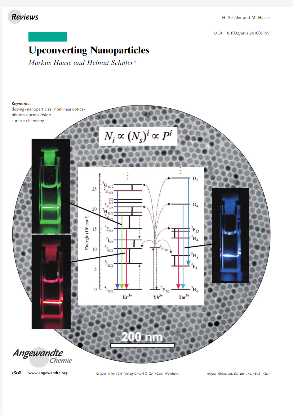
Upconverting Nanoparticles
Markus Haase and Helmut Sch?fer*
Angewandte
Chemie
Keywords:
doping ·nanoparticles ·nonlinear optics ·photon upconversion ·surface chemistry
5808
https://www.doczj.com/doc/9d7890288.html,
2011Wiley-VCH Verlag GmbH &Co.KGaA,Weinheim
Angew.Chem.Int.Ed.2011,50,5808–5829
1.Introduction
In linear optics it is assumed that optical properties are independent of the intensity of the incident light.The expression “nonlinear optics”is usually used to describe all other phenomena for which the optical properties of the material depend on the radiant flux density of the exciting light.Nonlinear optics,an integral part of contemporary optics,is based on a number of nonlinear phenomena and processes.Photon upconversion (UC)is one such phenom-enon and is characterized by the conversion of long-wave-length radiation,for instance infrared or near infrared (NIR)radiation,to short-wavelength radiation,usually in the visible range.The upconversion process proceeds by different mechanisms,which are summarized and discussed in detail in several review articles [1–3]and can be roughly divided into three classes:APTE effect (for addition de photon par transferts d ’energie),later also named ETU for energy-transfer upconversion,[4,5]excited-state absorption (ESA),and photon avalanche (PA).It is worth mentioning that the expression “upconversion”is sometimes used to describe the consequence of these mechanisms,that is,the conversion from long-wavelength to short-wavelength radiation,and sometimes for a specific mechanism itself.
All three mechanisms are based on the sequential absorption of two or more photons by metastable,long-lived energy states.This sequential absorption leads to the population of a highly excited state from which upconversion emission occurs.In the case of ESA,the emitting ions sequentially absorb at least two photons of suitable energy to reach the emitting level (Figure 1).In ETU,one photon is absorbed by the ion,but subsequent energy transfer from neighboring ions results in the population of a highly excited state of the emitting ion (Figure 1).Energy-transfer steps between two ions,both in excited states,leading to emission lines at short wavelength were first mentioned by Auzel in 1966.[6,7]
ETU and ESA should not be confused with two other nonlinear optical processes,simultaneous two-photon absorp-tion (STPA)[1,8–10]and second-harmonic generation (SHG),which is efficient if coherent excitation sources with suffi-ciently high power are used.[11–14]Several early reviews focused on the synthesis and application of upconversion phosphors.[4,5,15,16]
Important requirements for photon upconversion,such as long lifetimes of the excited states and a ladder-like arrange-ment of the energy levels with similar spacings,are realized for certain ions of the d and f elements.A large number of suitable hosts doped with transition-metal ions (3d,4d,5d)have been reported to show upconversion,for example Ti 2+-,[17,18]Ni 2+-,[19–22]Mo 3+-,[23,24]Re 4+-,[23,25,26]or Os 4+-doped solids.[27–30]Actinide-doped materials have also been inves-U pconversion (UC)refers to nonlinear optical processes in which the
sequential absorption of two or more photons leads to the emission of light at shorter wavelength than the excitation wavelength (anti-Stokes type emission).In contrast to other emission processes based on
multiphoton absorption,upconversion can be efficiently excited even at low excitation densities.The most efficient UC mechanisms are present in solid-state materials doped with rare-earth ions.The
development of nanocrystal research has evoked increasing interest in the development of synthesis routes which allow the synthesis of highly efficient,small UC particles with narrow size distribution able to form transparent solutions in a wide range of solvents.Meanwhile,high-quality UC nanocrystals can be routinely synthesized and their solu-bility,particle size,crystallographic phase,optical properties and shape can be controlled.In recent years,these particles have been discussed as promising alternatives to organic fluorophosphors and quantum dots in the field of medical imaging.
From the Contents
1.Introduction
5809
2.Selection of Suitable Dopants and Host Materials
5810
3.Synthesis,Growth,and
Properties of Rare-Earth-Doped Nanocrystals 58124.Surface Functionalization by Modification of the Ligand Shell and the Particle Surface 58205.Application of Upconversion Nanocrystals
58206.Conclusions and Outlook
5822
Figure 1.UC processes for lanthanide-doped crystals:a)excited-state absorption,b)energy-transfer upconversion.d :photon excitation,a :energy transfer,c :emission.Reproduced from reference [47]by permission of The Royal Society of Chemistry.
[*]Prof.Dr.M.Haase,Dr.H.Sch?fer
Inorganic Chemistry I,University of Osnabrück Barbarastrasse 7,49069Osnabrück (Deutschland)E-mail:helmut.schaefer@uos.de
5809
Angew.Chem.Int.Ed.2011,50,5808–5829
2011Wiley-VCH Verlag GmbH &Co.KGaA,
Weinheim
tigated with respect to upconversion.[31,32]These systems require low temperatures,show poor optical properties,and are therefore at present mainly a subject of basic research.
High upconversion efficiencies even at room temperature, however,are observed for lanthanide-doped solids.The most efficient UC phosphor to date,Yb3+-and Er3+-doped NaYF4, was introduced by Menyuk et al.in1972[33]and Kano et al.in 1973[34]Owing to their outstanding properties,UC materials have been proposed for several applications,such as lasers,[11,35–37]solar cells,[38]wave guides,[39,40]and display devices.[41]
The availability of cheap semiconductor lasers together with the rise of nanoscience increased interest in the design of suitable synthesis procedures for nanocrystalline upconver-sion materials.In analogy to semiconductor nanocrystals (quantum dots),the aim was to synthesize small UC nano-crystals with high luminescence efficiency that form trans-parent solutions in a wide range of solvents.In comparison with bulk luminescent material,small luminescent particles show a classical drawback,namely poor luminescent effi-ciency.Core–shell architectures helped to overcome this problem(see Section3.4).Dispersible upconverting nano-phosphors show only low cytotoxicity,[42–46]and since excita-tion with NIR-light causes only a very low autofluorescence background of the biological materials,they seem to be a promising alternative for organic dyes or quantum dots in biological tagging experiments.
As the development and investigation of UC nanophos-phors has become an essential part of materials science, several reviews have already been published.[47–49,460]This Review presents the current state of affairs in the area of lanthanide-doped UC nanocrystals,with emphasis on the synthesis and investigation of lanthanide-doped nanoparticles (NPs).Despite the fact that the number of published articles related to this field has increased dramatically and therefore interferes with the clarity,one aim of this account is to give an almost complete general survey with respect to the relevant literature.2.Selection of Suitable Dopants and Host Materials
An inorganic upconversion phosphor consists of a crys-talline host and a dopant(usually lanthanide ions)added in low concentrations.The dopant provides luminescent centers, and the host lattice with its crystal structure provides a matrix to bring these centers into optimal position.[50–52]The ion-to-ion distance and spatial arrangement is especially important in the case of so-called sensitized luminescence,as will be discussed in detail in Section2.2.2(ETU mechanism).[53] Many lanthanide-doped host materials are able to emit visible light under NIR excitation,but highly efficient upconversion requires a good tuning between host lattice, dopant ions,and dopant concentration.
2.1.Choice of Host Lattice
The choice of the host lattice determines the distance between the dopant ions,their relative spatial position,their coordination numbers,and the type of anions surrounding the dopant.The properties of the host lattice and its interaction with the dopant ions therefore have a strong influence on the upconversion process.With regard to the ETU mechanism (Figure2),Er3+is excited into the4F7/2state in two steps.The
2H
11/2
and the4S3/2states are populated by nonradiative multiphonon relaxation steps.From these levels,the ion may either return directly to the4I15/2ground state or may first populate the4F9/2state by an additional nonradiative multi-phonon relaxation step.In the first case green light is emitted, in the second case red light.To achieve efficient excitation of the2H11/2state and,hence,intense upconversion emission,the
4I
11/2
state must be strongly populated.In other words,an efficient upconversion process benefits from a long4I11/2 lifetime.[2,54]In fluoride materials,long lifetimes of the excited states are commonly observed because of the low phonon energies(ca.350cmà1)[69]of the crystal lattice(Table1). However,lattice impurities may increase the multiphonon relaxation rates between the metastable states,thereby reducing the overall visible emission intensity.[55]Small non-radiative losses are also observed for lattices containing heavy halogenides,but these materials suffer from low chemical stability.Metal oxides present the desired chemical
stability,
Markus Haase received his PhD in1989
with Prof.A.Henglein from the Technical
University in Berlin.After postdoctoral
research at UC Berkeley with Prof.A.P.
Alivisatos,he moved to the Philips Research
Laboratories in Aachen,Germany.In1996,
he joined the group of Prof.H.Weller at the
University of Hamburg,where he finished
his Habilitation in2001.He received the
Nernst–Haber–Bodenstein Prize of the
Deutsche Bunsengesellschaft for Physical
Chemistry in2002.Since2004he has been
professor at the University of Osnabrück.His
research interests include the synthesis and application of inorganic nano-
particles and luminescent materials.
Helmut Sch?fer studied chemistry at the
Carl von Ossietzky University of Oldenburg
and received his PhD in2001with Prof.M.
Weidenbruch for his work on organogerma-
nium compounds.As a postdoctoral fellow,
he moved to the Institute of Material Sci-
ence(IWT)Bremen,German Aerospace
Center Cologne,and to the University of
Osnabrück.Since2004he has been a
researcher in the group of Prof.Markus
Haase.His research interests are closely
connected with materials science and include
the investigation of alternative synthesis
routes to known compounds as well as the synthesis of novel inorganic
compounds with particular characteristics.
https://www.doczj.com/doc/9d7890288.html, 2011Wiley-VCH Verlag GmbH&Co.KGaA,Weinheim Angew.Chem.Int.Ed.2011,50,5808–5829
but conventional oxygen-based systems often exhibit large phonon energies above 500cm à1[56](Table 1).
Host lattices based on cations like Na +,Ca 2+and Y 3+with ionic radii close to those of the lanthanide dopant ions prevent the formation of crystal defects and lattice stress,and therefore generally Na +and Ca 2+fluorides are superior host materials for upconversion phosphors.[57–62]The upconversion efficiency of,for instance,NaYF 4:Yb 3+,Er 3+is 20times higher than that of La 2O 3:Yb 3+,Er 3+and 6times higher than that of La 2(MoO 4)3:Yb 3+,Er 3+.[63]Nevertheless,Yb 3+,Er 3+doped phosphors based on oxide type matrices are also commer-cially available [65]and were used,for instance,by Kuningas et al.[66,67]
Among the fluoride hosts,hexagonal NaYF 4(b -NaYF 4)is the most efficient host material for green and blue upconver-sion phosphors known to date.[1,11,51,68–79]The UC efficiency of the green emission in hexagonal-phase NaYF 4:Yb 3+/Er 3+is approximately 10times stronger than that in cubic NaYF 4:Yb 3+/Er 3+.[50]The question why it is superior to all other host materials in terms of upconversion luminescence efficiency was thoroughly investigated,particularly by Güdel et al.[51]It could be shown that the generally high emission intensities of this phosphor originate from the interaction of dopant ions located on two different lattice sites.[51]
Especially in the case of small particles,we must take additional effects into consideration.Since additional non-radiative pathways exists for ions at or near the surface and even for ions in the core of the particles,[80,81]quenching is possible even when pure fluoride matrices are used.[461]
2.2.Dopant Systems Available for Upconversion 2.2.1.Single Doping
Owing to the long lifetime of the excited states,an excited lanthanide ion may sequentially absorb a second photon of suitable energy at comparatively low excitation densities and reach an ever-higher excited state.If within one ion energy gaps between three or more subsequent energy levels are very similar,sequential excitation to a highly excited state is possible with a single monochromatic light source,since each absorption step requires the same photon https://www.doczj.com/doc/9d7890288.html,nthanide ions with an energy-level structure suitable for this type of excitation include Er 3+,Tm 3+,and Ho 3+,which are currently the most common emitters (activators)in upconversion phosphors.[47]The efficiency of the upconversion process is particularly high for Er 3+,where a similar energy gap of about 10350cm à1exists between two subsequent pairs of energy levels,namely between the 4I 11/2and 4I 15/2states and between the 4I 11/2and the 4F 7/2states (Figure 2,left).In addition,the energy difference between 4F 9/2and 4I 13/2states is in the same region,and hence at least three different transitions in Er 3+ions are induced by IR photons of the same energy,thus leading to emission of green and red light (Figure 2,left,and Figure 3a–c)after the sequential absorption of two
photons.
Figure 2.Energy-level diagram,upconversion excitation,and visible emission schemes for the Yb 3+-sensitized Er 3+and Tm 3+systems.Arrows indicate radiative and nonradiative energy transfer and multi-phonon relaxation processes.Reproduced from reference [59]Copy-right Wiley-VCH 2004.
Table 1:Highest phonon lattice energy of commonly used matrices for rare-earth ions.Reproduced with permission from reference [56].Copy-right Wiley-VCH 2007.Material
Highest Phonon Energy [cm à1]phosphate glass 1200silica glass 1100fluoride glass
550chalcogenide glass 400LaPO 41050YAG [a]860YVO 4600LaF 3300LaCl 3
240
[a]YAG:yttrium aluminum
garnet.
Figure 3.Photographs of the upconversion luminescence in 1wt %colloidal solutions of nanocrystals excited with 973nm light.a)Total upconversion luminescence of the NaYF 4:20%Yb 3+,2%Er 3+.b,c)The same luminescence through red (b)and green (c)color filters.d)Total upconversion luminescence of the Yb 3+,Tm 3+-doped sample.Repro-duced from reference[59].Copyright Wiley-VCH 2004.
5811
Angew.Chem.Int.Ed.2011,50,5808–5829
2011Wiley-VCH Verlag GmbH &Co.KGaA,Weinheim
https://www.doczj.com/doc/9d7890288.html,
Blue emission is observed in systems doped with Tm3+after the absorption of four photons(Figure2,right,and Fig-ure3d).Several reports are focused on the synthesis and investigation of(single)rare-earth-ion-doped nanomateri-als.[69,74,82–174]
Since4f–4f transitions are Laporte-forbidden,inefficient absorption of the exciting light can be a serious problem, especially in the case of thin samples of lanthanide doped materials.In principle,the absorption can be improved by increasing the concentration of the lanthanide dopant in the material.But radiationless deactivation can occur,and the process of cross-relaxation severely limits the range of useful dopant concentrations.The upper limit of concentration depends on the exact distance of the lattice sites occupied by lanthanide ions,but in most upconversion materials the concentration of Er3+does not exceed3%and of Tm3+not about0.5%.At these concentrations,however,the absorp-tion of light is insufficient,which hinders the practical use of these materials as phosphors.[47]To increase the absorption of lanthanide-doped phosphors,the materials are often addi-tionally doped with strongly absorbing ions called sensitizers, which should also ensure efficient energy transfer to the activator.
2.2.2.Codoping:Systems with Activators and Sensitizers
In the case of upconversion phosphors based on Er3+or Tm3+,the most widely used sensitizer for980nm light is the Yb3+ion.The energy separation of the2F7/2ground state of Yb3+and its2F5/2excited state matches well the transition energy between the4I11/2and4I15/2states and also the4F7/2and 4I
11/2
states of Er3+,thus allowing for efficient(quasi-)resonant energy transfer between the two https://www.doczj.com/doc/9d7890288.html,ually,Yb3+is codoped into the lattice in high concentrations(18–20%). Yb3+is also the standard sensitizer for Tm3+-doped upcon-version materials,in which the energy of four980nm photons is transferred from the Yb3+ions to one Tm3+ion(Figure2). Both ion couples(Er3+/Yb3+and Tm3+/Yb3+)show the highest upconversion efficiency when doped into hexagonal-phase NaYF4(b-NaYF4).Apart from high upconversion efficien-cies,the emission of Yb3+,Er3+codoped phosphors saturates only at high excitation densities.Saturation is found at 100W cmà2for NaYF4:Yb3+,Er3+.[175]Many reports on Yb3+,Er3+-and Yb3+,Tm3+-doped nanocrystalline[43,44,46,52,55, 57–62,64,71–73,75,77–79,87,90,91,93,102,176–262]and macrocrystalline[33,50, 65,66,68–70,120,166,204,208,263–292]upconversion phosphors have been published.Yb3+is a common sensitizer not only for Er3+,Tm3+ systems but also for Ho3+[293]and Pr3+[294]ions.The activator–sensitizer concept can also be applied to transition-metal ions. For instance,Cs2NaYCl6:Os4+,Er3+or Cs2NaYbCl6:Mo3+ showing energy transfer between Er3+and Os4+and between Mo3+and Yb3+,respectively,were investigated by Güdel and co-workers.[2,295]3.Synthesis,Growth,and Properties of Rare-Earth-Doped Nanocrystals
3.1.Nanocrystals Based on Oxidic Materials
There have been numerous reports on the properties of nanocrystalline upconversion materials that are based on lanthanide-doped oxide hosts.[54,56,57,64,65,71,82,84,85,87–92,94–96,98, 105,127,128,167,180,181,190,197–199,202,205,209,219,220,256,262,278,296–332]Several classes of materials have been investigated,such as binary oxide host lattices,[82,94,167,180,181,197,199,305]ternary oxide host lattices,[85,198]phosphates,[64]vanadates,[84]molybdates,[278]tita-nates,[88]zirconates,[314]silicates,[56,312]hydroxides[57,333]and oxysulfides.[197,333,334]
In2003we reported the first observation of photon upconversion in transparent colloids.[64]The green and red emission bands as well as the absorption spectrum can be taken from Figure4.The Er3+-doped LuPO4and YbPO4
nanoparticles were prepared by coprecipitation in a method analogous to that used to prepare LaPO4:Ce3+,Tb3+and CePO4:Tb3+nanocrystals.[335,336]Bulk LaPO4:Ce3+,Tb3+is a commercially applied lamp phosphor.[337,338]Redispersible Er3+-doped YVO4nanocrystals were synthesized in a hydro-thermal process by Kong and co-workers.[84]Surface modifi-cation of rare-earth-doped Y2O3nanoparticles leads to water-redispersible NPs.[315]Despite their comparatively low upcon-version efficiency,this type of NP is still in the focus of scientific investigation[300,315]and has already been used for applications in bioimaging[180,315](see also Section
5).
Figure4.a)Absorption spectrum and assignments of the
YbPO4:5%Er3+colloid.b)Upconversion luminescence spectrum and assignments after excitation at10230cmà1(see arrow)with a laser power of300mW.Reproduced from reference[64].Copyright Wiley-VCH2003.
https://www.doczj.com/doc/9d7890288.html, 2011Wiley-VCH Verlag GmbH&Co.KGaA,Weinheim Angew.Chem.Int.Ed.2011,50,5808–5829
3.2.Nanocrystals Based on Fluorides
Fluorides as host lattices for upconversion fluorescent particles benefit from many properties(see also Section2.1), and the most frequently synthesized and investigated upcon-version fluorescent NPs consist of fluoride sublattices.
3.2.1.Rare-Earth-Doped LnF3Nanoparticles
The optical properties of bulk LaF3:Yb3+,Er3+[339–341]and bulk YF3:Yb3+,Er3+[272,341,342]were already investigated in the late1960s and early1970s,respectively.Depending on the ionic radius of the lanthanide ion,[343]the lanthanide trifluor-ides crystallize either in a trigonal(tysonite LaF3type,space group P3ˉc1)or an orthorhombic structure(b-YF3type,space group Pnma).[344]At room temperature,the trifluorides of the lighter lanthanides(Ln=La–Nd)form the trigonal structure only,[345–348]whereas for the heavier lanthanides(Ln=Dy–Lu) and yttrium,the orthorhombic structure is observed.[349–352] From Ln=Sm–Tb,the LnF3system is dimorphic.[343] The first synthesis procedures for LaF3nanoparticles were reported in2001by Dang and co-workers[353]and by Zhang et al.[354]One year later,redispersible LaF3nanocrystals doped with rare-earth ions such as Eu3+,Er3+,Nd3+,and Ho3+were synthesized by van Veggel and Stouwdam.[80] These nanoparticles display luminescence emission in the NIR region and are therefore of interest for optical tele-communication.[80]In the following years,an increasing number of papers on the synthesis of rare-earth-doped lanthanide trifluoride nanocrystals was published.The syn-thesis and the properties of YF3nanoparti-cles,[58,233,262,283,332,356–358]YbF3nanocrystals,[276]and LaF3[178,182,193,200,217,253,262,355,359–369]and LuF3nanoparti-cles[370,371]have been intensively investigated.
Yan et al.achieved highly uniform,monodisperse LaF3 nanoplatelets of about16nm in size by thermolysis of La(CF3COO)3in a hot oleic acid/octadecene solution.[372]In one of the most cited articles of2005,Li and Yan[58]described a two-step synthesis method for doped YF3nanoparticles.By doping these particles with the ion couple Yb3+/Er3+,red, green,and an unusually strong411nm blue upconversion emission band were obtained.[58]In double logarithmic plots of the emission intensity versus excitation intensity,straight lines with a slope of about two are obtained for the green and red emissions,thus indicating that two IR photons are absorbed per emitted photon(Figure5a;[58]see also Güdel et al.and Yi et al.)[373,374]For the blue emission,a slope of three was observed,corresponding to a three-photon process (Figure5b;[58]see also Güdel et al.)[373]
Chow and Yi investigated colloidal LaF3:Yb3+,Er3+; LaF3:Yb3+,Ho3+;and LaF3:Yb3+,Tm3+particles with a small
particle size and a narrow size distribution.[362]Upconversion fluorescent trifluoride nanoparticles have not lost their popularity to date and therefore are still in the focus of investigation.In2008Hu et al.prepared hydrophobic as well as amphiphilic UC LaF3:Yb3+,Er3+and LaF3:Yb3+,Ho3+ nanoparticles with an average particle size of15nm (Figure6)in an oleic acid containing aqueous solution.[217]They showed photographs of the upconversion luminescence
of a colloidal solution of LaF3:Yb3+,Ho3+in water(Figure7).
https://www.doczj.com/doc/9d7890288.html,nthanide-Doped M(RE)F4Nanoparticles(M=Li,Na,K;
RE=Rare Earth)
The phase equilibrium within the bulk fluoride host system MF(RE)F3has been intensively investigated
and
Figure5.Power dependence of YF3:Yb3+,Er3+upconversion intensity
shown by double logarithmic plots.a)Emission peaks at663.5,552,
and526nm.b)411nm blue emission peak.Reproduced with permis-
sion from reference[58].Copyright Wiley-VCH
2005.
Figure6.TEM images of upconversion LaF3:Yb3+,Ho3+nanocrystals. Reproduced with permission from reference[217].Copyright American Chemical Society2008.
5813
Angew.Chem.Int.Ed.2011,50,5808–5829 2011Wiley-VCH Verlag GmbH&Co.KGaA,Weinheim https://www.doczj.com/doc/9d7890288.html,
discussed during the past six decades.[453–458]Upconversion phosphors based on bulk,microcrystalline,or sub-micro-crystalline NaYF 4have been intensively investigated,and the results are summarized in several reports.[33,34,50,375–378]Because of their outstanding properties,Yb 3+,Er 3+-and Yb 3+,Tm 3+-doped NaYF 4are the most frequently investigated materials.Fewer reports discuss M(RE)F 4host lattices other than NaYF 4,such as NaGdF 4,LiGdF 4,KYF 4,and LiLuF 4,or upconversion experiments using doping ions other than the classical couples Yb 3+,Er 3+and Yb 3+,Tm 3+.
Yb 3+,Er 3+-doped and undoped NaLuF 4microplates have been synthesized and investigated by Li et al.[379]Very recently not only the optical but also the magnetic properties of Yb 3+,Er 3+-doped NaGdF 4have been investigated by Hao et al.[380]Yb 3+,Er 3+-doped LiYF 4nanocrystals derived from trifluoroacetate precursors were reported by Yan et al.[381]
In LiYF 4:Nd 3+bulk material the avalanche effect,an effect also leading to upconversion phenomena,[382,383]has been observed below 60K.[384]The spectroscopic properties of Gd 3+-doped KYF 4and LiYF 4,Nd 3+-doped LiYF 4have been investigated by Sytsma,Khaidukov,and Guyot et al.,[385–387]and Meijerink et al.investigated Er 3+-doped LiYF 4.[388]Pr 3+-doped KYF 4and LiLuF 4as possible white emitters were synthesized and discussed by Toncelli et al.[389]Bulk KYF 4:Ln (Ln =Pr 3+,Er 3+,Tm 3+,Ho 3+,Yb 3+,Nd 3+,Er 3+)are well known as upconversion-pumped solid-state lasers.[129,150,390–395]A very remarkable result was achieved by Meijerink:Visible quantum cutting could be shown in case of Eu 3+-doped LiGdF 4.[396]
In 2004three research groups reported on the successful synthesis of small luminescing NaYF 4nanocrystals that formed transparent colloidal solutions.The first synthesis developed by Haase,Güdel et al.was based on the copreci-
pitation of NaYF 4:Yb 3+,Er 3+and NaYF 4:Yb 3+,Tm 3+nano-particles in the high-boiling solvent N -(2-hydroxyethyl)ethyl-enediamine (HEEDA).[59]The synthesis yielded transparent colloidal solutions of cubic-phase particles.The upconversion efficiency of such solutions was about eight orders of magnitude higher than those of the colloids of lanthanide-doped phosphate nanocrystals reported by the same groups.[59,64]
Photos displaying this emission as a beam of light in solution became a standard eye-catcher in papers dealing with upconversion nanoparticles later on (Figure 3).Although the synthesis procedure was a strong improvement compared to earlier routes,the method suffers from several drawbacks,such as a rather broad particle size distribution (5–30nm)and the formation of the less efficient cubic a -phase of NaYF 4.In the same year,Yi,Chen et al.reported on the synthesis of Yb 3+,Er 3+-doped cubic NaYF 4particles by co-precipitation of the rare-earth chlorides with NaF in the presence of ethyl-enediamine tetraacetic acid (EDTA).[62]The spherical,as-prepared particles showed a narrow size distribution of 32–46nm diameter.Annealing of dry powders of these particles at 400–6008C led to larger particles with the hexagonal phase showing strong UC luminescence efficiency.
Also in 2004,the first small hexagonal-phase (b -phase)Yb 3+
,Er 3+-doped NaYF 4particles with a mean size of 25nm were synthesized in acetic acid solution by the Li group (Figure 8a).[73]The quality of the NaYF 4nanocrystals improved significantly when the procedure developed by Yan et al.for the synthesis of uniform LaF 3particles with well-defined size and shape was modified and applied to the preparation of NaYF 4and other NaLnF 4particles (Fig-ure 8b).[372]The method,based on the thermal decomposition of trifluoroacetates in solvent mixtures of oleic acid and octadecene,was further refined by several groups and is now a common route to monodisperse and uniform NaYF 4nanocrystals in the cubic and the hexagonal
phase.[75,79,93,186,192,194,201,207]
The synthesis procedure was trans-ferred to the generation of NaYF 4for the first time by Chow and Yi in 2006.[186]They reported on the formation of very small hexagonal NaYF 4:Yb 3+,Er 3+nanoparticles when the decomposition reaction is performed in pure oleylamine
at
Figure 7.Room-temperature upconversion luminescence spectra of oleic acid treated LaF 3:Yb 3+,Ho 3+nanocrystals (2mg mL à1)in cyclohex-ane and glycol monomethyl ether treated LaF 3:Yb 3+,Ho 3+nanocrystals in water under CW excitation at 980nm (power ca.800mW).CW =continous wave,mPEG =poly(ethylene glycol)monomethyl ether.Inset:a photograph of glycol monomethyl ether treated LaF 3:Yb 3+,Ho 3+nanocrystals showing an almost pure green color.
Reproduced with permission from reference [217].Copyright American Chemical Society
2008.
Figure 8.a)TEM image of NaYF 4:Yb 3+,Er 3+nanocrystals prepared in acetic acid using EDTA.Reproduced with permission from refer-ence [73].Copyright Wiley-VCH 2005.b)TEM images of the edge-to-edge superlattices of LaF 3nanoplates.Inset is the SAED pattern.(SAED =selected area electron diffraction)Reproduced with permis-sion from reference [372].Copyright American Chemical Society 2005.
https://www.doczj.com/doc/9d7890288.html,
2011Wiley-VCH Verlag GmbH &Co.KGaA,Weinheim
Angew.Chem.Int.Ed.2011,50,5808–5829
3308C.To our knowledge,this is the first example of a successful synthesis of b -NaYF 4particles with a particle size in the range of 10nm.[186]The particles could be dispersed in organic solvents,were uniform in shape,and showed a narrow size distribution ((10.5?0.7)nm)as deduced from TEM and dynamic light scattering measurements (DLS,(11.1?1.3)nm,Figure 9).Capobianco et al.generated cubic phase lanthanide-doped NaYF 4nanoparticles,hexagonal in shape with an average size of 27.6nm and a standard deviation of 1.6nm (Figure 10).[79]
One advantage of the use of trifluoroacetates is the rapid formation of reactive fluoride compounds at elevated temper-atures.Drawbacks mentioned in the literature are the emission of toxic gases,the requirement of high reaction temperatures,and the rather narrow temperature window of the decomposition (less than 108C),which leads to difficulties with respect to the reproducibility.[245]Therefore,efforts were made in the development of alternative synthesis routes that also allow an exact control of the phase,shape,and size of the particles.
In 2008Li and Zhang reported on different methods for the synthesis of pure hexagonal-phase NaYF 4nanocrystals in solvent mixtures of oleic acid and octadecene at 3008C.[61]In their procedure the metal trifluoroacetates are replaced by
in situ generated rare-earth oleates,NaOH,and NH 4F.[61]Alternatively,stearic acid and trioctylphosphine oxide (TOPO)were used instead of oleic acid,and an eicosene/trioctylamine mixture replaced octadecene as high-boiling solvent.[215]The particles were of outstanding quality in terms of size distribution (average size 21nm)and shape uniformity (nanospheres and hexagonal plates depending on the amount of oleic acid (Figure 11).[215]Using a synthesis route with NaF
and rare-earth oleates as precursors,Chen and co-workers published a method yielding doped b -NaYF 4NPs with high size uniformity and an extremely narrow size distribution of (28.25?0.76)nm in 2009.[245]Impregnating nanocrystals of a -NaYF 4doped with Er 3+and Yb 3+into a porous,anodized aluminum oxide (AAO)membrane led to nanotubes com-posed of close-packed uniform nanocrystals [285](Figure 12).
Doping of cubic or hexagonal NaYF 4nanocrystals with Yb 3+
,Er 3+and Yb 3+,Tm 3+ions leads to emission bands in the green or red and blue spectral regions,respectively (Figure 3).In several papers,strategies to expand the range of emission colors were investigated.In 2008,Nann et al.showed that a large number of emission colors can be realized by simply mixing colloids of upconversion nanoparticles containing different dopant ions.Colloids of NaYbF 4:Er 3+,NaYbF 4:Tm 3+,NaYF 4:Yb 3+,and NaYbF 4:Ho 3+with emission bands in the green and red (NaYbF 4:Er 3+and NaYbF 4:Ho 3+);mainly blue and IR (NaYF 4:Yb 3+);and blue and IR (NaYbF 4:Tm 3+)regions were synthesized and combined in different concentrations.[211]By doping the same NaYF 4host with all three ions Yb 3+,Tm 3+,and Er 3+and adjusting their concentrations,Wang and Liu obtained colloids with bluish to whitish (NaYF 4:Yb 3+,Tm 3+,Er 3+)and greenish-yellowish to redish (NaYF 4:Yb 3+,Er 3+)overall color output (Figure 13).
[60]
Figure 9.a)TEM image of NaYF 4:20%Yb 3+,2%Er 3+nanocrystals at a magnification of 50000 .b)TEM image of NaYF 4:20%Yb 3+,2%Er 3+nanocrystals at a higher magnification of 150000 .Reproduced with permission from reference [186].Copyright Wiley-VCH
2006.
Figure 10.TEM images of spherical NaYF 4:2%Er 3+,20%Yb 3+nano-crystals.a)Low magnification;b)high magnification.Reproduced with permission from reference [79].Copyright American Chemical Society
2007.
Figure 11.TEM images of NaYF 4:Er 3+,Yb 3+nanospheres (a,b)and nanoplates (c,d)at different magnifications.Reproduced with permis-sion from reference [215].Copyright IOP Publishing 2008.
5815
Angew.Chem.Int.Ed.2011,50,5808–5829
2011Wiley-VCH Verlag GmbH &Co.KGaA,Weinheim
https://www.doczj.com/doc/9d7890288.html,
Advantages of the oleate-based synthesis are the narrow particle size distribution,the high luminescence efficiency,and the high phase purity of the particles.Although the hexagonal bulk phase is thermodynamically preferred at low temperatures,[407]the cubic a -phase is obtained when the synthesis is performed at lower temperatures (below 3008C),thus indicating that the reaction in oleic acid is controlled by kinetics.In contrast,we could show that the simple solid-state reaction between NH 4F,Na 2CO 3,and the rare-earth carbo-
nates yields nanocrystalline b -phase NaYF 4even at room temperature.[228]If the same reaction is performed in oleyl-amine or in a mixture of oleylamine and oleic acid,hexagonal-phase NaYF 4nanocrystals are obtained that display a broad particle size distribution from 4to 10nm.
A powerful tool for phase and size control is additional doping with Gd 3+ions.[399]Gd 3+ions were incorporated by Wang et al.into upconverting NaYF 4:Yb 3+,Er 3+nanocrystals at different doping levels,leading to a ternary doped NaYF 4:Yb 3+,Er 3+,Gd 3+system.[399]Without additional Gd 3+ions a mixture of cubic and hexagonal phases was found under the chosen reaction conditions.With increased Gd 3+concen-trations the transformation from cubic to hexagonal structure becomes more and more noticeable,and the size of the corresponding particles decreases.Doping of binary doped NaYF 4:Yb 3+,Er 3+or ternary doped NaYF 4:Yb 3+,Er 3+,Tm 3+with Gd 3+,leading to the corresponding ternary or quaternary doped lanthanide species,was used for fine tuning of the visible color of the upconverting nanocrystals.[399]
There are now a large number of reports dealing with the synthesis and investigation of high quality lanthanide doped cubic [44,46,55,59–63,71,72,75,78,79,93,117,177,186,187,189,194,196,200,201,204,208,212,213,222,224,226,261,262,275,283,397–404]
and hexagonal NaYF 4parti-cles.
[46,62,72,73,78,93,117,176,177,183,186,191,192,194–196,201,203,204,207,215,216,221,225,399–401,405,462]
Especially the development of a suitable syn-thesis that is able to form small hexagonal nanoparticles faced problems because of the tendency toward regular-shaped nanoplates or rods in the micrometer and sub-micrometer range.[93]
In 2008we investigated nanosized Yb 3+,Er 3+-doped cubic KYF 4particles about 13nm in size synthesized by the HEEDA route.[214]The nanocrystals showed only poor luminescence efficiency,which could be improved signifi-cantly by coating with undoped material (see Section 3.4.1).
Finally,chelating ligands and donor ligands such as EDTA,citrate,TOPO,trioctylphosphine (TOP),and poly-(vinyl pyrrolidone)(PVP)have been employed in addition to the amphiphilic surfactant to reduce the particle size and to prevent the particles from agglomeration.[61,62,187,201,408]3.2.3.Ln-Doped Fluoride Nanocrystals with Other Stoichiome-tries:MF 2,MYF 5,MY 2F 7Most of the work on upconversion nanocrystals is focused on fluoride materials with M(RE)F 4stoichiometry.However,there are some examples of upconversion nanocrystals with compositions other than M(RE)F 4or (RE)F 3discussed in Section 3.2.1.and 3.2.2.
The structure of cubic NaYF 4(space group Fm 3
ˉm ,no.225)is isomorphic with CaF 2.In the NaF–MF 3system the charge on the lanthanide ions is balanced by an appropriate number of sodium ions,and this is the case not only for the fluorite-type structure but also for the nonstoichiometric phases with varying compositions given by Na 0.5àx M 0.5+x F 2+2x ,where 0 x 1=7.[409]Several groups investigated the doping of alkaline-earth fluoride nanocrystals with lanthanide ions.Efficient upconversion emission is reported for some of these systems.Li et al.reported in 2009on the successful hydro-thermal synthesis of high-quality
monodisperse
Figure 12.a)Magnified cross-sectional SEM image of rare-earth fluo-ride nanotube arrays after removing the AAO template.b)Bottom-view
SEM image showing rare-earth fluoride nanotubes oriented in a
perpendicular fashion on the substrate.Reproduced with permission from reference [285].Copyright Springer
2009.
Figure 13.Room-temperature upconversion emission spectra of a)NaYF 4:Yb 3+,Er 3+(18and 2mol%),b)NaYF 4:Yb 3+,Tm 3+(20and 0.2mol %),c)NaYF 4:Yb 3+,Er 3+(25–60and 2mol %),and d)NaY-F 4:Yb 3+,Tm 3+,Er 3+(20,0.2,and 0.2–1.5mol%)particles in https://www.doczj.com/doc/9d7890288.html,piled luminescent photos showing corresponding colloidal solu-tions of e)NaYF 4:Yb 3+,Tm 3+(20and 0.2mol %),f–j)NaY-F 4:Yb 3+,Tm 3+,Er 3+(20,0.2,and 0.2–1.5mol%),and k–n)NaY-F 4:Yb 3+,Er 3+(18–60and 2mol%).The samples were excited at 980nm with a 600mW diode laser.Reproduced with permission from refer-ence [60].Copyright American Chemical Society 2008.
https://www.doczj.com/doc/9d7890288.html,
2011Wiley-VCH Verlag GmbH &Co.KGaA,Weinheim
Angew.Chem.Int.Ed.2011,50,5808–5829
CaF 2:Yb 3+,Er 3+nanocrystals about 10nm in size (Figure 14)in a water/ethanol solvent mixture.[77]They found that the upconversion efficiency of the CaF 2particles is even slightly
stronger than cubic Yb 3+,Er 3+-doped NaYF 4particles of the same size.In this so-called liquid–solid–solution (LSS)process developed by Wang,Li et al.,a general phase transfer between the interfaces takes place.[262]Yan ’s group modified the trifluoroacetate method for NaYF 4nanocrystals for the synthesis of alkaline-earth-metal difluorides.Uniform alka-line-earth-metal fluoride MF 2(M =Mg,Ca,Sr)particles with various shapes (3D nanoneedle networks of tetragonal MgF 2,nanoplates and nanopolyhedra of cubic CaF 2,nanoplates and nanowires of cubic SrF 2)were synthesized by the thermolysis of alkaline-earth-metal trifluoroacetates (M(CF 3COO)2)in hot surfactant solutions.The best upconversion properties were found in the case of Yb 3+,Er 3+-doped SrF 2after modification of the surface.[223]The obtained particle sizes were 13nm (80–170nm)(MgF 2),33nm 45nm (CaF 2),36nm 25nm (SrF 2,Figure 15)and 1000nm for BaF 2.Kumar et al.reported on the optical properties of CaF 2:Er 3+nanocrystals doped into a hexafluoroisopropylidene (6F)-based polymer composite.[99,410]Using the Langmuir–Blodgett (LB)technique,Yan et al.prepared films of CaF 2nano-particles 9.5nm 2nm in size.[239]
Small Yb 3+,Tm 3+-doped BaYF 5particles (15nm 5nm in size)were obtained by the Capobianco group by the thermal decomposition of rare-earth trifluoroacetates in solvent mixtures of oleic acid and octadecene containing barium acetylacetonate.[227]The particles displayed intense blue light from the 1G 4!3H 6Tm 3+transition under excitation in the NIR region in transparent solution.
We reported on the synthesis and optical properties of Yb 3+
,Er 3+doped RbY 2F 7and CsY 2F 7nanoparticles.[259,411]Two synthesis routes were described,which led to particles with broad size distributions in the range of 6to 60nm for the rubidium compound and 8–50nm for the cesium compound.The structural and optical properties of colloidal Ln 3+,Yb 3+-doped KY 3F 10nanocrystals were reported by Capobianco and co-workers.[412]
Finally,there have been several reports on nanoscale glass–ceramics in which,for example,rare-earth-doped PbF 2nanoparticles are considered to be responsible for the emission of visible light under NIR excitation [102,123,124,413,414].
3.3.Investigation of Single Upconversion Nanocrystals
Luminescing nanoparticles are usually characterized by ensemble-averaged measurements of their optical properties.Characterization of the upconversion luminescence on the single-particle level was performed by the groups of Wua and Nann in 2008and 2009,respectively.[234,415]Individual NaY-F 4:Yb 3+,Er 3+particles deposited on a silicon nitride mem-brane [234]or attached to a gold nanosphere [415]were spectro-scopically investigated and found to be nonblinking and photostable (Figure 16).[234]
3.4.The Core–Shell Concept
The luminescence efficiency of nanoparticles is usually smaller than that of the corresponding bulk materials,owing to the large surface-to-volume ratio of nanoparticles.In the case of lanthanide-based upconversion materials,the pres-ence of surface ligands with high-energy vibrational modes such as OH or NH 2groups can lead to quenching of the excited lanthanide states by multiphonon relaxation process-es.If the concentration of a dopant in the host lattice is high,as in the case of Yb 3+,energy transfer from the center of the particle to the surface through adjacent dopant ions may further decrease the efficiency.The standard strategy to reduce energy losses on the nanoparticle surface is to coat the particle with an appropriate shell material.In the case of lanthanide-doped nanomaterials,this shell material should not allow any kind of energy transfer from the core of the particle to its outer surface.It should be kept in mind,however,that the luminescence or upconversion efficiency is significantly increased only if the interface between
the
Figure 14.TEM image of CaF 2:Yb 3+,Er 3+nanocrystals.Reproduced with permission from reference [77].Copyright American Chemical Society
2009.
Figure 15.TEM and high-resolution (HR)TEM (inset)images of SrF 2nanoplates.Reproduced with permission from reference [223].Copy-right American Chemical Society 2009.
5817
Angew.Chem.Int.Ed.2011,50,5808–5829
2011Wiley-VCH Verlag GmbH &Co.KGaA,Weinheim
https://www.doczj.com/doc/9d7890288.html,
particle core and the shell is of high quality,that is,if the interface contains a much smaller number of quenching sites than the surface of the core particle before coating.
In recent years authors have begun to quantify the effectiveness of the light conversion that occurs in the designed UC phosphors and UC nanoparti-cles.[59,69,175,214,228,259,411,416]We used bulk hexagonal NaY-F 4:18%Yb 3+,2%Er 3+
reference material and determined the visible-light output of different UC nanoparticles in comparison with this bulk sample.[59,214,259,411]The efficiency ratios between the reference sample and the UC nano-particles strongly depend on the laser power,the constitution,and the size of the NPs and are in the range of 100to 150000.[59,214,259,411]In 2009we compared the emitted light intensity of hexagonal Yb 3+,Er 3+-doped NaYF 4NPs (7nm in size)with cubic NPs of the same constitution (28nm in size).At 1.78W laser power,the efficiency ratio was approximately 10.[228]In terms of the determination of the absolute quantum yield (QY)of bulk UC phosphors,Page et al.did the pioneering work.[175]For the green emission of Yb 3+,Er 3+-doped hexagonal NaYF 4,the QY was 4%.Based on the setup used by Page et al.,very recently also the absolute quantum yield of colloidal hexagonal NaYF 4:Yb 3+,Er 3+nanoparticles was determined by Boyer and van Veggel.[416]They found values in the range of 0.005to 0.3,depending on the particle size.[416]
3.4.1.Particles with a Passivating Shell of Undoped Material If the excitation energy is mainly transferred to the particle surface through neighboring dopant ions,the most straightforward choice for the shell material is the pure (i.e.,undoped)host material of the core particle.The formation of core–shell particles with small lattice mismatch between the
core and the shell material has been intensively investigated for semiconductor nanoparticles as well as for some doped nanomaterials with large bandgaps.[336,367,417]More recently,synthesis procedures for core–shell particles of lanthanide fluoride material have been developed.The formation of passivating shells on rare-earth-doped LaF 3,[178]NaYF 4,[61,72,192,221,224,463]KYF 4,[214]and NaGdF 4[418]and on undoped YF 3[419]and NaYF 4[420]particles have been published by several authors.An individual case is reported by Yang and co-workers,who investigated particles consisting of an undoped core with Yb 3+,Er 3+-doped NaYF 4on the periphery of the particle.[421]
A significant enhancement of the upconversion fluores-cence by depositing undoped core material on the surface of rare-earth-doped NaYF 4core particles was demonstrated for the first time by Yi and Chow (Figure 17).[192]A luminescent enhancement of nearly 30times was achieved by a 1.5nm thick shell of undoped b -phase NaYF 4.The article is one of the most cited in the field.
NaYF 4:Yb 3+,Er 3+//NaYF 4core–shell nanoparticles with different crystallographic phases of the core and the shell were discussed by Mai et al.in their 2007report.[72]A synthesis procedure for b -NaYF 4:Yb 3+,Er 3+//a -NaYF 4core–shell par-ticles with a size of about 30nm is given,but a hard proof for the existence of both crystallographic phases within one particle remains to be shown.
Usually,the successful deposition of undoped material on the surface of the core particles is deduced from an increase of the average particle size in combination with an enhancement of the luminescence efficiency.[192,214]Site-selective spectros-copy was also used to identify dopant sites on the particle surface and to show that these sites are converted into bulk sites when undoped material is deposited onto the core particle.[422]If the core and the shell consist of materials displaying different image contrasts in electron microscopy,like in the case of NaYF 4//SiO 2core–shell particles,the core–shell structure and the uniformity of the shell thickness can be visualized directly (Figure 18).The quality of the core–shell structure can also be investigated by X-ray photoelectron spectroscopic (XPS)measurements.[423–426]Ideally,a synchro-tron radiation source is used,which allows tuning of the photon energy of the X-rays exciting the sample.At low photon energies,only electrons of elements located in the outmost layers of the particle can reach the detector,whereas at high photon energies electrons from the core can also escape the particle,and the composition of the whole core–shell particle is probed.[336,427]Recently,van Veggel and co-workers used this technique in combination with energy-dispersive X-ray spectroscopy (EDX)to demonstrate the existence of the core–shell structure of b -NaYF 4//b -NaGdF 4nanocrystals.[420]
3.4.2.Particles with Shells Containing Dopants
In the majority of cases published,the shell is inert and its sole role is to increase the luminescence efficiency of the core (see Section 3.4.1).Starting in 2008,different groups reported on core–shell nanoparticles in which the shell also contains optically active centers.[209,221,251,428]These efforts were
related
Figure 16.Individual UCNPs on a silicon nitride membrane.Confocal upconverted luminescent image of individual UCNPs.The TM-SEM image (inset)taken at the upper left corner region of the optical image shows that the individual diffraction-limited luminescent spots are emitted from individual UCNPs.Reproduced with permission from reference [234].Copyright National Academy of Science (USA)2009.
https://www.doczj.com/doc/9d7890288.html,
2011Wiley-VCH Verlag GmbH &Co.KGaA,Weinheim
Angew.Chem.Int.Ed.2011,50,5808–5829
to different aims,such as enhancement of the luminescence or the tunability of the upconversion fluorescence.
By doping the particle core with Tm 3+and the shell with Er 3+nanoparticles,tunable multicolor fluorescence was
obtained which displayed no quenching of the Tm 3+emission.J.Zhang et al.reported on hexagonal-phase core-shell-structured NaYF 4:Yb 3+,Tm 3+//b -NaYF 4:Yb 3+,Er 3+(AB)[251]and on core–shell–shell b -NaYF 4:Yb 3+,Tm 3+//b -NaY-F 4:Yb 3+,Er 3+//b -NaYF 4:Yb 3+,Tm 3+(ABA)nanocrystals.[251]The sandwich ABA nanocrystals showed a remarkable enhancement of the Er 3+fluorescence.
Capobianco and co-workers showed a strong enhance-ment of the green and red emission bands of NaGd-F 4:Yb 3+,Er 3+particles by growing a shell of Yb 3+-doped NaGdF 4on the surface of the cores.[428]Additional energy transfer from excited Yb 3+ions in the shell to the Er 3+ions in the core increases the overall efficiency of the particles (Figure 19).The emission of the active core–active shell
particles is more intense by a factor of approximately three (green)and ten (red)compared to standard core–shell particles composed of a doped core and an inert shell.3.4.3.Particles with Silica Shells
A large number of different colloidal nanomaterials have been coated with shells of amorphous silica.These shells are usually generated by St?ber type reactions based on the controlled hydrolysis of tetraalkoxy silanes.Silica as shell material benefits from many advantages.Silica is chemically inert,optically transparent,and there are a large number of procedures for coupling functional molecules to the surface of SiO 2.Thus,the biofunctionalization of nanoparticles is possible by anchoring suitable molecules to the SiO 2surface of core–shell particles,[45]and protocols for the conjugation of biomolecules to a silica surface are well-established.[429–431]
In 2005Nann and Darbandi transferred the technique to fluoride nanoparticles in order to functionalize the surface of YF 3.[419]The surface modification of rare-earth-doped NaYF 4nanoparticles was reported by Zhang and Li one year later.[61]They succeeded in growing a silica shell with adjustable thickness in the range of 2–10nm on the surface of
PVP-Figure 17.a)Structure of upconversion nanoparticles.b)Photographs of the upconversion luminescence:green from NaYF 4:Yb 3+,Er 3+and blue from NaYF 4:Yb 3+,Tm 3+nanoparticles in solution.Reproduced with permission from reference [192].Copyright American Chemical Society
2007.
Figure 18.TEM images of silica-coated poly(vinyl pyrrolidone)/NaY-F 4:Yb 3+,Er 3+nanocrystals.Left:thickness of the layer approximately 10nm.Right:with a very thin silica layer.Reproduced with permission from reference [179].Copyright Wiley-VCH
2006.
Figure 19.Schematic illustration of the active core–active shell nano-particle architecture showing the absorption of NIR light by the Yb 3+-rich shell (red)and subsequent energy transfer to the Er 3+,Yb 3+-doped core (green),which leads to upconverted blue,green,and red
emissions.Reproduced with permission from reference [428].Copy-right Wiley-VCH 2009.
5819
Angew.Chem.Int.Ed.2011,50,5808–5829
2011Wiley-VCH Verlag GmbH &Co.KGaA,Weinheim
https://www.doczj.com/doc/9d7890288.html,
stabilized Yb3+,Er3+-and Yb3+,Tm3+-doped cubic NaYF4 nanocrystals(Figure18).
By incorporating tetramethylrhodamine isothiocyanate (TRITC),fluorescein isothiocyanate(FITC),or quantum dots into a silica shell grown on Yb3+,Er3+-doped or Yb3+,Tm3+-doped NaYF4NPs,Zhang and co-workers were able to tune the emission spectra of the upconversion particles.[221]The new feature of their approach is the observed fluorescence resonance energy transfer(FRET) between the excited dopant ions and the organic dyes or quantum dots encapsulated in the silica shell.The FRET therefore leads to luminescence emission of the dyes or quantum dots upon excitation of the core–shell particle in the NIR region.
4.Surface Functionalization by Modification of the Ligand Shell and the Particle Surface
Rapid advances in the diagnostics and monitoring of infectious and genetic diseases are one of the driving forces behind the development of more sensitive and efficient markers for labeling experiments.The ability of upconversion nanoparticles(UCNPs)to emit visible light upon excitation with low-intensity NIR light should significantly reduce the autofluorescence background of the biological material in biolabeling experiments.To be suitable for biotagging appli-cations,however,the particles must be compatible with biological substrates,should show only specific binding to the biological target,and must be soluble(dispersible)in aqueous media.
Without post-synthesis treatment,UCNPs are not disper-sible in polar media.[432,433]The desired properties are obtained either by exchanging or manipulating the organic ligands coordinated to the surface,by addition of amphiphilic polymers interacting with the apolar groups of the surface ligands,or by surface silanization.These methods have
already been reviewed in the reports by Wang and Liu and by Capobianco and Vetrone.[47,48]Therefore,only some very recent results are listed here.
The most popular method to obtain water dispersibility is coating of the NaYF4NPs with a shell of SiO2prepared by a sol–gel process.[42,45,62,201,221,246,464]To link these particles to biomolecules,reactive functional moieties such as amino or carboxylic acid groups are required.In the case of SiO2-coated particles,biofunctional amine group can be introduced by treating the SiO2surface with3-aminopropyltrimethoxy-silane,as shown by Shan and Ju,[201]or with N-[3-(trimeth-oxysilyl)propyl]ethylenediamine(AEAPTMS),as shown by Jiang et al.[246]Carboxylic acid functionalized NaYF4nano-phosphors were synthesized by direct oxidation of the oleic acid ligands using the Lemieux–von Rudloff reagent.[206]The presence of carboxylic acid groups on the one hand confers solubility of the particles in water and on the other hand ensures that streptavidin can easily be linked through covalent bonds(Figure20).The replacement of the ligands that are attached to the particle surface after the synthesis by ligands bearing polar groups is another technique to render the particles water-soluble.We found that1-hydroxyethane-1,1-diphosphonic acid(HEDP)strongly binds to the surface of NaYF4:Yb3+,Er3+nanocrystals,resulting in high colloidal solubility of the particles in water.[55]Van Veggel and co-workers report on the exchange of oleate ligands coordinated to Yb3+,Tm3+-and Yb3+,Er3+-doped NaYF4particles with a polyethylene glycol phosphate ligand.[406]
5.Application of Upconversion Nanocrystals
5.1.Application in Biology and Diagnostics
Many diagnostic techniques imply the specific binding of reagents,so-called reporter molecules,to target molecules. Today,a variety of such reporter molecules exist,including, for instance,radioisotopes,enzymes,and fluorescent markers. High-quality upconversion NPs linked to biological macro-molecules are investigated as fluorescent markers for imaging biological processes as well,as they benefit from a narrow particle size distribution,high photostability,narrow emission bandwidths,good biocompatibility,and a high signal-to-noise ratio owing to the weak autofluorescence background
gen-Figure20.Mechanism of the generation of carboxylic acid functional-ized upconversion nanoparticles from oleic acid capped precursors. Reproduced with permission from reference[206].Copyright American Chemical Society2008.
https://www.doczj.com/doc/9d7890288.html, 2011Wiley-VCH Verlag GmbH&Co.KGaA,Weinheim Angew.Chem.Int.Ed.2011,50,5808–5829
erated by NIR excitation.[460]Moreover,the penetration depth into biological tissue is high for NIR radiation. Biological applications of upconverting NPs range from the simple introduction of luminescing NPs into biological systems to the specific detection of biomolecules using different techniques,for instance,FRET-based chemosensing. Depending on the nature of the investigated biomaterial,the detection of biomolecules can be divided into in vitro and in vivo detection.Biological applications of UCNPs were recently reviewed by Lui et al.[460]and Wolfbeis et al.[465]
5.1.1.In Vitro Detection
The first demonstration of the potential of upconversion materials in diagnostics,in this case of rare-earth-doped yttrium oxysulfide,was reported about10years ago by Tanke et al.and by Hampl et al..[297,434–436]At that time,the size of upconversion particles was in the range of hundreds of nanometers,and only surface labeling could be shown.[434] Moreover,the level of nonspecific binding between reagents and markers was high,thus reducing the detection sensitivity. Nevertheless,the signal-to-noise ratio could be dramatically improved compared to conventional reporters.By using
similar400nm UC particles,Hampl et al.achieved a detec-tion limit of10pg human chorionic gonadotropin in a100m L sample,a tenfold improvement over conventional reporter systems like colloidal gold.[436]To use upconversion particles analogous to luminescent molecular dyes,however,small (less than30nm)upconversion nanoparticles with narrow size distribution and high luminescence efficiency are required,which were not available at that time.In fact,it took several years until smaller particles suitable for this purpose became available.
The strong interaction of biotin and avidin(or streptavi-din)is widely used in bioanalytical applications.[437–442]For instance,bioconjugation of silica-coated LaF3:Ln3+NPs to fluorescein isothiocyanate(FITC)was shown.[178]The FITC is excited by direct480nm irradiation.[178]Successful bioconju-gation of the biotinylated LaF3//SiO2upconversion core–shell particles to FITC–avidin(Figure21)was shown by a signifi-cant25-fold increase of the FITC fluorescence compared to the same system where the particles were not biotinylated.[178] In a parallel report,the same group showed that the optical properties of the biotinylated inorganic NPs were nearly identical to the unfunctionalized NPs,which is a prerequisite for designing a UCNP-based biosensor.[443]
A different upconversion biosensor based on the FRET between bioconjugated UCNPs and gold NPs was developed in Li’s group.[184]To our knowledge it is the first example of using the FRET technique for a bioassay based on UCNPs.In this case,the FRET system consists of biotinylated50nm NaYF4:Yb3+,Er3+NPs and biotinylated7nm Au NPs.The emission band of the UCNPs at520nm exactly fits the plasmon absorption band of the gold NPs.Quenching there-fore occurs in the case of close proximity of both particles. This requirement is fulfilled when avidin is added,which works as a coupling(i.e.,network-forming)compound between the particles owing to the sensitive and selective interaction between avidin and biotin.The luminescence of the system when excited by NIR light was gradually quenched
with increasing amounts of avidin added to the system,and so
trace amounts of avidin could be detected.
5.1.2.In Vivo Detection
The simplest in vivo application of upconverting nano-crystals is their introduction into living organisms and the detection of the distribution of nanoparticles inside the organism.Nanoparticles of Yb3+,Er3+-doped yttria,for instance,are found to present good biocompatibility when inoculated in worms,and upon excitation in the NIR, agglomerates of the particles can clearly be detected.[180]In
larger organisms such as mice,UCNPs could be detected even
in depths of around10mm.[43]
RNA interference(RNAi)is a powerful gentechnological method for the specific suppression of genes and has broad applications ranging from functional gene analysis to target-
based therapy.[444–446]The method is based on small interfer-
ence RNA(siRNA),that is,short pieces of double-strand
RNA21–23nucleotides in length.Imaging of siRNA can be performed with a special FRET system based on a siRNA-staining acceptor dye.This acceptor dye is usually combined
with an organic donor dye,but the latter can be replaced with quantum dots,as shown by Gao et al.[447]But especially for in
vivo applications,quantum dots suffer from their potential toxicity and strong autofluorescence background.[184,448,449]In
a recent report Zhang and Jiang used rare-earth codoped
NaYF4UCNPs for the intracellular investigation of siRNA in
live cells.[450]The UCNPs,which display an emission band at
540nm,work as the FRET donor,and the siRNA intercalat-
ing dye BOBO-3,with a broad absorption band at550nm,
served as the FRET acceptor.If the distance between the
BOBO-3stained siRNA and the biomodified UCNPs is short, energy transfer from the NIR-excited nanoparticle to BOBO-
3is efficient and leads to an emission at600nm(Figure
22).
Figure21.Preparation and bioconjugation strategy of silica-coated
LaF3:Ln3+nanoparticles to FITC–avidin(not to scale).
APTMS=(CH3O)3Si(CH2)3NH2.TEOS=(C2H5O)4Si,biotin-NHS=bio-
tin N-hydroxysuccinimide activated ester(see lower left corner).
Reproduced with permission from reference[178].Copyright Wiley-
VCH2006.
5821
Angew.Chem.Int.Ed.2011,50,5808–5829 2011Wiley-VCH Verlag GmbH&Co.KGaA,Weinheim https://www.doczj.com/doc/9d7890288.html,
5.2.Other Applications
Apart from the biological application,UCNPs are dis-cussed for some other devices.[466,467]In recent reports,a combination of UCNPs and dithienylethene (DTE)is dis-cussed for optical memory applications and remote-control photoswitching.[238,363,459]DTE photoswitches are based on ring-closing and ring-opening reactions induced by ultraviolet and visible light,respectively.To sensitize the system to NIR light,Branda et al.developed composite films consisting of DTE and either NaYF 4:Yb 3+,Er 3+or NaYF 4:Yb 3+,Tm 3+nanoparticles [238].When the UCNPs are excited in the NIR,the emitted energy,either visible or UV radiation depending on the doping,is transferred to the DTE molecule,thus resulting in a ring-opening or ring-closing reaction (Fig-ure 23a).The switching between the two states of the system is accompanied by a color change of the composite material along the path of the IR light (Figure 23b).Photopatterns on the basis of upconversion nanoparticles useful for potential applications in the field of security were designed by Kim et al.[451]
6.Conclusions and Outlook
Regarding various applications,upconverting nanoparti-cles benefit from their unique properties as they show 1)high sensitivity of detection because of the lack of autofluores-cence background,2)less toxic components than quantum dots (QDs),and 3)high penetration depths in combination with photostability and optical tunability.Many different dopant–host compositions have been developed and inten-sively investigated.Most scientists concur that in terms of
biomedical applications,hexagonal-structured lanthanide-doped NaYF 4is currently the most promising candidate.
Meanwhile,there is a large number of reports dealing with the successful generation of high-quality lanthanide-doped hexagonal NaYF 4NPs showing narrow size distribution and high luminescence efficiency.Although there is a large body of literature describing various different synthesis procedures for hexagonal NaYF 4particles in substance,only two differ-ent synthesis routes can be extracted from the current literature that lead to particles which fulfill the requirements.In the most known cases,the particles were prepared either by the trifluoroacetate route (transferred to NaYF 4by Chow and Yi)or by the oleate route (by Zhang and Li).[186,215]Apart from further improvement of the synthesis procedures for generat-ing lanthanide-doped b -NaYF 4nanoparticles to obtain desired optical properties,size,and size distribution of the particles,and to make the synthesis more user-friendly,the discovery of new upconversion ions,combinations of ions,and host materials will remain areas of intense research.
The use of upconverting nanocrystals in nucleic acid assays and immunoassays in in vitro und in vivo imaging has been demonstrated over the past five years.Very often,applications are still limited to the simple introduction of luminescing NPs into biological systems and detection of the particles themselves.For the replacement of molecular fluorescent markers (molecular weight ca.300g mol à1),[452]which allow estimation of the position of single molecules within cellular structures with nanometer precision,particles with sizes in the region of 20nm are still too
large.
Figure 22.FRET-based UCNP/siRNA-BOBO3complex system.Energy is transferred from the donor (UCNP)to the acceptor (BOBO-3)upon excitation of the nanoparticles at 980nm.Reproduced with permission from reference [450].Copyright Wiley-VCH
2006.
Figure 23.a)Photoswitching realized by transition between electroni-cally and structurally different isomers of DTE.b)Reactions
A)1a +NaYF 4:Tm 3+,Yb 3+!1b and B)1b +NaYF 4:Er 3+,Yb 3+!1a upon irradiation by NIR light (980nm).The light beams to the right (A)and (B)correspond to the direction of the laser beam.The irradiation in (A)was carried out twice with perpendicular orientations.The small squares in all images are the cutout holes in the sample holder,through which the absorbance was measured.Reproduced with
permission from reference [238].Copyright American Chemical Society 2009.
https://www.doczj.com/doc/9d7890288.html,
2011Wiley-VCH Verlag GmbH &Co.KGaA,Weinheim
Angew.Chem.Int.Ed.2011,50,5808–5829
Therefore,for most advanced imaging applications in the field of biomedicine,for example the specific imaging of molecular and cellular events in the case of molecular neuroimaging,the overall quality of current upconversion NPs is still insufficient.In general,many methods still suffer from low reproducibility,mainly relevant to overall surface conditions that impair the colloidal stability and the lumines-cence efficiency.
So we dare to claim that despite the good progress, essential challenges still remain to be faced before these particles can fully reach their potential regarding the practical application in clinical settings by ultimate consumers.
The authors thank the colleagues involved in the peer review for the helpful comments.
Received:August17,2010
Revised:January21,2011
Published online:May30,2011
[1]F.Auzel,Chem.Rev.2004,104,139.
[2]H.U.Güdel in Topics in Current Chemistry,Vol.214(Ed.:H.
Yersin),Springer,New York,2001,p.1.
[3]D.R.Gamelin,H.U.Güdel,Acc.Chem.Res.2000,33,235.
[4]F.Auzel,Proc.IEEE1973,61,758.
[5]J.Wright in Topics in Applied Physics,Vol.15(Ed.: D.J.
Diestler,F.K.Fong,K.F.Freed,R.Kopelman,J.C.Wright), Springer,New York,1976,p.239.
[6]F.Auzel,C.R.Acad.Sci.1966,262,1016.
[7]F.Auzel,C.R.Acad.Sci.1966,263,819.
[8]K.K?nig,J.Microsc.2000,200,83.
[9]W.M.McClain,R.E.Harris in Excited States(Ed.:E.C.Lim),
Academic Press,New York,1978,S.1.
[10]Y.Dong,J.Xu,G.Zhou,G.Zhao,M.Jie,L.Y.Yang,L.Su,J.
Qiu,W.Feng,L.Lin,Opt.Express2006,14,1899.
[11]R.Scheps,Prog.Quantum Electron.1996,20,271.
[12]N.Bloembergen,Phys.Rev.1962,127,1918.
[13]L.R.Dalton,Chem.Mater.1995,7,1060.
[14]W.R.Zipfel,R.M.Williams,R.Christie,A.Yu Nikitin,B.T.
Hyman,W.W.Webb,https://www.doczj.com/doc/9d7890288.html,A2003,100,12, 7075.
[15]Y.Mita,E.Nagasawa,NEC Res.Dev.1974,33,61.
[16]G.F.Garlick,J.Contemp.Phys.1976,17,127.
[17]O.S.Wenger,H.U.Güdel,Inorg.Chem.2001,40,5747.
[18]S.M.Jacobsen,H.U.Güdel,J.Lumin.1989,43,125.
[19]R.Moncorge,F.Auzel,J.M.Breteau,Philos.Mag.B1985,51,
489.
[20]O.S.Wenger,H.U.Güdel,R.Valiente,High-Pressure Res.
2002,22,57.
[21]O.S.Wenger,H.U.Güdel,Inorg.Chem.2001,40,157.
[22]O.S.Wenger,H.U.Güdel,R.Valiente,Phys.Rev.B2001,64,
235116.
[23]D.R.Gamelin,H.U.Güdel,J.Am.Chem.Soc.1998,120,
12143.
[24]D.R.Gamelin,H.U.Güdel,J.Phys.Chem.B2000,104,10222.
[25]D.R.Gamelin,H.U.Güdel,Inorg.Chem.1999,38,5154.
[26]M.Wermuth,H.U.Güdel,J.Phys.Condens.Matter2001,13,
9583.
[27]M.Wermuth,H.U.Güdel,Chem.Phys.Lett.1997,281,81.
[28]M.Wermuth,H.U.Güdel,J.Lumin.2000,87–89,1014.
[29]M.Wermuth,H.U.Güdel,J.Am.Chem.Soc.1999,121,10102.
[30]M.Wermuth,H.U.Güdel,J.Chem.Phys.2001,114,1393.
[31]N.A.Stump,G.M.Murray,G.D.Delcul,R.G.Haire,J.R.
Peterson,Radiochim.Acta1993,61,129.[32]P.J.Deren,W.Strek,E.Zych,J.Drozdzynski,Chem.Phys.
Lett.2000,332,308.
[33]N.Menyuk,K.Dwight,J.W.Pierce,Appl.Phys.Lett.1972,21,
4,159.
[34]T.Kano,T.Suzuki,A.Suzuki,S.Minagawa,J.Electrochem.
Soc.1973,120,C87.
[35]W.Lenth,R.M.Macfarlane,Opt.Photon.News1992,3,8.
[36]W.Lenth,R.M.Macfarlane,J.Lumin.1990,45,346.
[37]M.F.Joubert,Phys.Rev.B1993,48,10031.
[38]A.Shalav, B.S.Richards,T.Trupke,K.W.Kramer,H.U.
Güdel,Appl.Phys.Lett.2005,86,13503.
[39]C.Strohhofer,A.Polman,J.Appl.Phys.2001,90,4314.
[40]P.G.Kik,A.Polman,J.Appl.Phys.2003,93,5008.
[41]E.Downing,L.Hesselink,J.Ralston,R.M.Macfarlane,
Science1996,273,1185.
[42]A.R.Jalil,Y.Zhang,Biomaterials2008,29,4122.
[43]D.K.Chatterjee,A.J.Rufaihah,Y.Zhang,Biomaterials2008,
29,937.
[44]M.Nyk,R.Kumar,T.Y.Ohulchanskyy,E.J.Bergey,P.N.
Prasad,Nano Lett.2008,8,3834.
[45]J.Shan,J.Chen,J.Meng,J.Collins,W.Soboyejo,J.S.Friedberg,
Y.Ju,J.Appl.Phys.2008,104,094308.
[46]F.Wang,D.K.Chatterjee,Z.Li,Y.Zhang,X.Fan,M.Wang,
Nanotechnology2006,17,5786.
[47]F.Wang,X.Liu,Chem.Soc.Rev.2009,38,976.
[48]F.Vetrone,J.A.Capobianco,Int.J.Nanotechnol.2008,5,1306.
[49]P.Rahman,M.Green,Nanoscale2009,1,214.
[50]K.W.Kramer,D.Biner,G.Frei,H.U.Güdel,M.P.Hehlen,
S.R.Luthi,Chem.Mater.2004,16,1244.
[51]A.Aebischer,M.Hostettler,J.Hauser,K.Kr?mer,T.Weber,
H.-U.Güdel,H.-B.Bürgi,Angew.Chem.2006,118,2869;
Angew.Chem.Int.Ed.2006,45,2802.
[52]A.Aebischer,S.Heer,D.Biner,K.Kr?mer,M.Haase,H.U.
Güdel,Chem.Phys.Lett.2005,407,124.
[53]M.P.Hehlen,M.L.F.Phillips,N.J.Cockroft,H.U.Güdel in
Encyclopedia of Materials:Science and Technology,Vol.10
(Ed.:E.J.Kramer),Pergamon/Elsevier,Oxford,2001,p.9456.
[54]X.Chen,E.Ma,G.Liu,J.Phys.Chem.C2007,111,10404.
[55]H.Sch?fer,P.Ptacek,K.K?mpe,M.Haase,Chem.Mater.2007,
19,1396.
[56]R.Diamente,M.Raudsepp,F.C.J.M.van Veggel,Adv.Funct.
Mater.2007,17,363.
[57]Z.Xu,C.Li,P.Yang,C.Zhang,S.Huang,J.Lin,Cryst.Growth
Des.2009,9,4752.
[58]R.Yan,Y.Li,Adv.Funct.Mater.2005,15,5,763.
[59]S.Heer,K.K?mpe,M.Haase,H.U.Güdel,Adv.Mater.2004,
16,2102.
[60]F.Wang,X.Liu,J.Am.Chem.Soc.2008,130,5642.
[61]Z.Li,Y.Zhang,Angew.Chem.2006,118,7896;Angew.Chem.
Int.Ed.2006,45,7732.
[62]G.Yi,H.Lu,S.Zhao,Y.Ge,W.Yang,D.Chen,L.-H.Gu,Nano
Lett.2004,4,2191.
[63]G.Blasse,B.C.Grabmaier,Luminescent Materials,1st ed.,
Springer,Berlin,1994,p.1.
[64]S.Heer,O.Lehmann,M.Haase,H.U.Güdel,Angew.Chem.
2003,115,3288;Angew.Chem.Int.Ed.2003,42,3179.
[65]T.Soukka,K.Kuningas,T.Rantanen,V.Haaslahti,T.Lovgren,
J.Fluoresc.2005,15,513.
[66]K.Kuningas,T.Rantanen,https://www.doczj.com/doc/9d7890288.html,onaho,T.L?lvgren,T.Soukka,
Anal.Chem.2005,77,7348.
[67]K.Kuningas,https://www.doczj.com/doc/9d7890288.html,onaho,H.P?kkil?,T.Rantanen,J.Rosen-
berg,T.L?vgren,T.Soukka,Anal.Chem.2006,78,4690.
[68]J.F.Suyver,J.Grimm,K.W.Kramer,H.U.Güdel,J.Lumin.
2005,114,53.
[69]J.F.Suyver,J.Grimm,M.K.van Veen, D.Biner,K.W.
Kr?mer,H.U.Güdel,J.Lumin.2006,117,1.
5823
Angew.Chem.Int.Ed.2011,50,5808–5829 2011Wiley-VCH Verlag GmbH&Co.KGaA,Weinheim https://www.doczj.com/doc/9d7890288.html,
[70]J.F.Suyver,A.Aebischer,S.García-Revilla,P.Gerner,H.U.
Güdel,Phys.Rev.B2005,71,125123.
[71]J.F.Suyver,A.Aebischer,D.Biner,P.Gerner,J.Grimm,S.
Heer,K.W.Kr?mer,C.Reinhard,H.U.Gudel,Opt.Mater.
2005,27,1111.
[72]H.-X.Mai,Y.-W.Zhang,L.-D.Sun,C.-H.Yan,J.Phys.Chem.C
2007,111,13721.
[73]J.H.Zeng,J.Su,Z.-H.Li,R.-X.Yan,Y.-D.Li,Adv.Mater.
2005,17,2119.
[74]P.Boutinaud,R.Mahiou,N.Martin,M.Malinowski,J.Lumin.
1997,72–74,809.
[75]J.-C.Boyer,F.Vetrone,L.A.Cuccia,J.A.Capobianco,J.Am.
Chem.Soc.2006,128,7444.
[76]R.Kumar,M.Nyk,T.Y.Ohulchanskyy, C.A.Flask,P.N.
Prasad,Adv.Funct.Mater.2009,19,853.
[77]G.Wang,Q.Peng,Y.Li,J.Am.Chem.Soc.2009,131,14200.
[78]L.Wang,Y.Li,Chem.Mater.2007,19,727.
[79]J.-C.Boyer,L.A.Cuccia,J.A.Capobianco,Nano Lett.2007,7,
847.
[80]J.W.Stouwdam,F.C.J.M.van Veggel,Nano Lett.2002,2,733.
[81]B.M.Tissue,Chem.Mater.1998,10,2837.
[82]S.Polizzi,S.Bucella,A.Speghini,F.Vetrone,R.Naccache,J.C.
Boyer,J.A.Capobianco,Chem.Mater.2004,16,1330. [83]https://www.doczj.com/doc/9d7890288.html,i,B.Chen,W.Xu,X.Wang,Y.Yang,Q.Meng,J.Alloys
Compd.2005,395,181.
[84]Y.Sun,H.Liu,X.Wang,X.Kong,H.Zhang,Chem.Mater.
2006,18,2726.
[85]F.Vetrone,J.-C.Boyer,J.A.Capobianco,A.Speghini,M.
Bettinelli,J.Phys.Chem.B2003,107,10747.
[86]Z.Xu,X.Kang,C.Li,Z.Hou,C.Zhang,D.Yang,G.Li,J.Lin,
Inorg.Chem.2010,49,6706.
[87]H.Guo,N.Dong,M.Yin,W.Zhang,L.Lou,S.Xia,J.Phys.
Chem.B2004,108,19205.
[88]A.Patra,C.S.Friend,R.Kapoor,P.N.Prasad,Chem.Mater.
2003,15,3650.
[89]A.Patra,P.Ghosh,P.S.Chowdhury,M.A.R.C.Alencar,W.
Lozano,B.N.Rakov,G.S.Maciel,J.Phys.Chem.B2005,109, 10142.
[90]A.Patra,C.S.Friend,R.Kapoor,P.N.Prasad,J.Phys.Chem.B
2002,106,1909.
[91]G.Chen,G.Somesfalean,Y.Liu,Z.Zhang,Q.Sun,F.Wang,
Phys.Rev.B2007,75,195204.
[92]X.Wang,X.Kong,Y.Yu,Y.Sun,H.Zhang,J.Phys.Chem.C
2007,111,15119.
[93]H.-X.Mai,Y.-W.Zhang,R.Si,Z.-G.Yan,L.-D.Sun,L.-P.You,
C.-H.Yan,J.Am.Chem.Soc.2006,128,6426.
[94]F.Vetrone,J.-C.Boyer,J.A Capobianco,A.Speghini,M.
Bettinelli,Nanotechnology2004,15,75.
[95]K.Soga,A.Okada,Y.Saito,Y.Kameyama,T.Konishi,J.
Photopolym.Sci.Technol.2007,20,7.
[96]Y.Suna,Y.Chena,L.Tian,Y.Yub,X.Kong,Q.Zengb,Y.
Zhang,H.Zhang,J.Lumin.2008,128,15.
[97]G.A.Kumar,C.W.Chen,R.E.Riman,Appl.Phys.Lett.2007,
90,093123.
[98]Y.Bai,K.Yang,Y.Wang,X.Zhang,Y.Song,https://www.doczj.com/doc/9d7890288.html,mun.
2008,281,2930.
[99]G.A.Kumar, C.W.Chen,J.Ballato,R.E.Riman,Chem.
Mater.2007,19,1523.
[100]R.Naccache, F.Vetrone, A.Speghini,M.Bettinelli,J.A.
Capobianco,J.Phys.Chem.C2008,112,7750.
[101]M.Yu,J.Lin,Z.Wang,J.Fu,S.Wang,H.J.Zhang,Y.C.Han, Chem.Mater.2002,14,2224.
[102]V.K.Tikhomirov,M.Mortier,P.Gredin,G.Patriarche,C.
G?rller-Walrand,V.V.Moshchalkov,Opt.Express2008,16,19, 14544.
[103]Y.Mao,T.Tran,X.Guo,J.Y.Huang,C.K.Shih,K.L.Wang, J.P.Chang,Adv.Funct.Mater.2009,19,748.[104]P.Zhang,S.Rogelj,K.Nguyen,D.Wheeler,J.Am.Chem.Soc.
2006,128,12410.
[105]J.A.Capobianco, F.Vetrone,T.D.Alesio,G.Tessari, A.
Speghini,M.Bettinelli,Phys.Chem.Chem.Phys.2000,2,3203. [106]S.Q.Man,E.Y.B.Pun,P.S.Chung,Appl.Phys.Lett.2000,77, 483.
[107]I.-I.Oprea,H.Hesse,K.Betzler,Phys.Status Solidi B2005, 242,12,R109.
[108]A.S.Oliveira,M.T.de Araujo, A.S.Gouveia-Neto,J.A.
Medeiros Neto,A.S.B.Sombra,Y.Messaddeq,Appl.Phys.
Lett.1998,72,753.
[109]C.B.de Araujo,L.S.Menezes,G.S.Maciel,L.H.Acioli,
A.S.L.Gomes,Y.Messaddeq,A.Florez,M.A.Aegerter,
Appl.Phys.Lett.1996,68,602.
[110]M.Shojiya,M.Takahashi,R.Kanno,Y.Kawamoto,K.Kadono, Appl.Phys.Lett.1995,67,2453.
[111]A.Remillieux,B.Jacquier,J.Lumin.1996,68,279.
[112]J.Fernandez,R.Balda,M.Sanz,https://www.doczj.com/doc/9d7890288.html,cha,A.Oleaga,J.L.
Adam,J.Lumin.2001,94–95,325.
[113]L.H.Acioli,J.T.Guo,C.B.de Araujo,T.Messaddeq,M.A.
Aegerter,J.Lumin.1997,72–74,68.
[114]R.Balda,M.Sanz,A.Mendorioz,J.Fernandez,L.S.Griscom, J.L.Adam,Phys.Rev.B2001,64,144101.
[115]Jacquier,J.Lumin.1994,60,175.
[116]Y.G.Choi,K.H.Kim,B.J.Lee,Y.B.Shin,Y.S.Kim,J.Heo,J.
Non-Cryst.Solids2000,278,137.
[117]F.Liu,E.Ma,D.Chen,Y.Yu,Y.Wang,J.Phys.Chem.B2006, 110,20843.
[118]X.Fan,J.Wang,X.Qiao,M.Wang,J.-L.Adam,X.Zhang,J.
Phys.Chem.B2006,110,5950.
[119]H.Yang,Z.Dai,J.Li,Y.Tian,J.Non-Cryst.Solids2006,352, 5469.
[120]Y.Kishi,S.Tanabe,J.Alloys Compd.2006,408–412,842. [121]Z.Pan,A.Ueda,R.Mu,S.H.Morgan,J.Lumin.2007,126,251. [122]N.Rakov,G.S.Maciel,M.L.Sundheimer,L.de S.Menezes,
A.S.L.Gomes,Y.Messaddeq, F.C.Cassanjes,G.Poirier,
S.J.L.Ribeiro,J.Appl.Phys.2002,92,16337.
[123]V.D.Rodriguez,V.K.Tikhomirov,J.Mendez-Ramos,J.del-Castillo,C.G?rller-Walrand,J.Nanosci.Nanotechnol.2009,9, 2072.
[124]J.Mendez-Ramos,V.K.Tikhomirov,V.D.Rodr?guez, D.
Furniss,J.Alloys Compd.2007,440,328.
[125]B.Henke, B.Ahrens,P.T.Miclea, C.Eisenschmidt,J.A.
Johnson,S.Schweizer,J.Non-Cryst.Solids2009,355,1916. [126]M.Yin,V.N.Makhov,N.M.Khaidukov,J.C.Krupa,J.Alloys Compd.2002,341,362.
[127]J.A.Capobianco,F.Vetrone,J.C.Boyer,J.Phys.Chem.B 2002,106,1181.
[128]F.Vetrone,J.C.Boyer,J.A.Capobianco,J.Phys.Chem.B 2002,106,5622.
[129]G.Huber,E.Heumann,T.Sandrock,K.Petermann,J.Lumin.
1997,72–74,1.
[130]T.Riedener,P.Egger,J.Hulliger,H.U.Güdel,Phys.Rev.B 1997,56,1800.
[131]J.Grimm,E.Beurer,P.Gerner,H.U.Güdel,Chem.Eur.J.
2007,13,1152.
[132]O.S.Wenger,C.Wickleder,K.W.Kr?mer,H.U.Güdel,J.
Lumin.2001,94–95,101.
[133]E.Beurer,J.Grimm,P.Gerner,H.U.Güdel,J.Am.Chem.Soc.
2006,128,3110.
[134]R.Balda,J.Fernandez,I.Saez de Ocariz,M.Voda,A.Garcia, J.Phys.Rev.B1999,59,9972.
[135]J.J.Ju,J.H.Ro,M.Cha,J.Lumin.2000,87–89,1045. [136]M.Malinowski,M.F.Joubert,B.Jacquier,Phys.Rev.B1994, 50,12367.
https://www.doczj.com/doc/9d7890288.html, 2011Wiley-VCH Verlag GmbH&Co.KGaA,Weinheim Angew.Chem.Int.Ed.2011,50,5808–5829
[137]J.Fernandez,M.Sanz,A.Mendorioz,R.Balda,J.P.Chami-nade,J.Ravez,https://www.doczj.com/doc/9d7890288.html,cha,M.Voda,M.A.Arriandiaga,J.
Alloys Compd.2001,323–324,267.
[138]M.Malinovski,B.Jacquier,B.,M.Bouazaoui,M.F.Joubert,C.
Linares,Phys.Rev.B1990,41,31.
[139]K.Holliday,D.L.Russell,B.Henderson,J.Lumin.1997,72, 927.
[140]M.Wermuth,T.Riedener,H.U.Güdel,Phys.Rev.B1998,57, 4369.
[141]P.Müller,M.Wermuth,H.U.Güdel,Chem.Phys.Lett.1998, 290,105.
[142]R.Burlot-Loison,M.Pollnau,K.Kr?mer,P.Egger,J.Hulliger,
H.U.Güdel,J.Opt.Soc.Am.B2000,17,2055.
[143]T.Riedener,H.U.Güdel,J.Chem.Phys.1997,107,2169. [144]X.Li,Q.Li,J.Wang,L.Li,J.Lumin.2007,124,351. [145]X.B.Chen,G.Y.Zhang,Y.H.Mao,Y.B.Hou,Y.Feng,Z.
Hao,J.Lumin.1996,69,151.
[146]A.S.L.Gomes,C.B.de Araujo,J.Lumin.1991,48,876. [147]Y.Wang,J.Ohwaki,J.Appl.Phys..1993,74,1272.
[148]Y.Wang,Jpn.J.Appl.Phys.1994,33,L334.
[149]R.M.Macfarlane,F.Tong,A.J.Silversmith,W.Lenth,Appl.
Phys.Lett.1988,52,1300.
[150]R.Brede,E.Heumann,J.Koetke,T.Danger,G.Huber,B.
Chai,Appl.Phys.Lett.1993,63,2030.
[151]J.-Y Allain,M.Monerie,H.Poignant,Electron.Lett.1990,26, 166.
[152]J.-Y Allain,M.Monerie,H.Poignant,Electron.Lett.1990,26, 261.
[153]M.Bresler,O.Gusev,E.Terukov,Y.Undalov,Phys.Status Solidi B2005,242,R82.
[154]R.Balda,J.Fernμndez, E.E.Nyein,U.H?mmerich,Opt.
Express2006,14,3993.
[155]P.Gerner,C.Reinhard,H.U.Güdel,Chem.Eur.J.2004,10, 4735.
[156]X.Wang,J.Song,H.Sun,Z.Xu,J.Qiu,Opt.Express2007,15, 1384.
[157]S.Chen,M.Wu,L.An,Y.Li,S.Wang,J.Am.Ceram.Soc.2007, 90,664.
[158]D.Dosev,I.M.Kennedy,M.Godlewski,I.Gryczynski,K.
Tomsia,E.M.Goldys,Appl.Phys.Lett.2006,88,011906. [159]E.Beurer,J.Grimm,P.Gerner,H.U.Güdel,Inorg.Chem.
2006,45,9901.
[160]C.Reinhard,R.Valiente,H.U.Güdel,J.Phys.Chem.B2002, 106,10051.
[161]P.Gerner,O.S.Wenger,R.Valiente,H.U.Güdel,Inorg.Chem.
2001,40,4534.
[162]S.R.Lüthi,M.Pollnau,H.U.Güdel,Phys.Rev.B1999,60,162. [163]T.Riedener,K.Kr?mer,H.U.Güdel,Inorg.Chem.1995,34, 2745.
[164]M.P.Hehlen,G.Frei,H.U.Güdel,Phys.Rev.B1994,50, 16264.
[165]M.P.Hehlen,R.A.McFarlane,R.N.Schwarz,H.U.Güdel, Phys.Rev.B1994,49,12475.
[166]P.Gerner,H.U.Güdel,Chem.Phys.Lett.2005,413,105. [167]F.Vetrone,J.-C.Boyer,J.A.Capobianco,A.Speghini,M.
Bettinelli,R.Krsmanovic,S.Polizzic,J.Electrochem.Soc.2005, 152,H19.
[168]M.Bouffard,T.Duvaut,J.P.Jouart,N.M.Khaidukov,M.F.
Joubert,J.Phys.Condens.Matter1999,11,4775.
[169]E.Sani,A.Toncelli,M.Tonelli,J.Phys.Condens.Matter2006, 18,2057.
[170]Y.Le Fur,N.M.Khaidukov,S.Aleonard,Acta Crystallogr.C 1992,48,2062.
[171]D.Wang,Y.Guo,G.Sun,J.Li,L.Zhao,G.Xu,J.Alloys Compd.2008,451,122.
[172]X.Wang,S.Xiao,X.Yang,J.W.Ding,J.Mater.Sci.2008,43, 1354.[173]C.Ma,P.A.Tanner,S.Xia,M.Yin,Optical Materials2007,29, 1620.
[174]N.M.Khaidukov,https://www.doczj.com/doc/9d7890288.html,m,D.Lo,V.N.Makhov,N.V.Suetin, Opt.Mater.2002,19,365.
[175]R.H.Page,K.I.Schaffers,P.A.Waide,J.B.Tassano,S.A.
Payne,W.F.Krupke,W.K.Bischel,J.Opt.Soc.Am.B1998,15,
3,996.
[176]L.Wang,Y.Li,Nano Lett.2006,6,1645.
[177]Y.Wei,F.Lu,X.Zhang,D.Chen,Chem.Mater.2006,18,5733. [178]S.Sivakumar,P.R.Diamente,F.C.J.M.van Veggel,Chem.
Eur.J.2006,12,5878.
[179]F.Tao,F.Pan,Z.J.Wang,W.L.Cai,L.Z.Yao,CrystEngComm 2010,12,4263.
[180]S.F.Lim,R.Riehn,W.S.Ryu,N.Khanarian,C.-K.Tung,D.
Tank,R.H.Austin,Nano Lett.2006,6,169.
[181]F.Vetrone,J.C.Boyer,J.A.Capobianco,A.Speghini,M.
Bettinelli,J.Phys.Chem.B2003,107,1107.
[182]Y.Wei,F.Lu,X.Zhang,D.Chen,Mater.Lett.2007,61,1337. [183]Y.Wei,F.Lu,X.Zhang,D.Chen,J.Alloys Compd.2007,427, 333.
[184]L Wang,R.Yan,Z.Huo,L.Wang,J.Zeng,J.Bao,X.Wang,Q.
Peng,Y.Li,Angew.Chem.2005,117,6208;Angew.Chem.Int.
Ed.2005,44,6054.
[185]G.-S.Yi,G.-M.Chow,Molecular Engineering of Biological and Chemical Systems(MEBCS)2006,https://www.doczj.com/doc/9d7890288.html,/1721.1/
30391.
[186]G.S.Yi,G.M.Chow,Adv.Funct.Mater.2006,16,2324.
[187]Y.Sun,Y.Chen,L.Tian,Y.Yu,X.Kong,J.Zhao,H.Zhang, Nanotechnology2007,18,275609.
[188]Z.Duan,J.Zhang,W.Xiang,H.Sun,L.Hu,Mater.Lett.2007, 61,2200.
[189]X.Liang,X.Wang,J.Zhuang,Q.Peng,Y.Li,Inorg.Chem.
2007,46,6050.
[190]X.Bai,H.Song,G.Pan,Y.Lei,T.Wang,X.Ren,S.Lu,B.
Dong,Q.Dai,L.Fan,J.Phys.Chem.C2007,111,13611.
[191]C.Li,J.Yang,Z.Quan,P.Yang,D.Kong,J.Lin,Chem.Mater.
2007,19,4933.
[192]G.-S.Yi,G.-M.Chow,Chem.Mater.2007,19,341.
[193]C.Liu,D.Chen,J.Mater.Chem.2007,17,3875.
[194]H.-X.Mai,Y.-W.Zhang,L.-D.Sun,C.-H.Yan,J.Phys.Chem.C 2007,111,13730.
[195]C.Li,Z.Quan,J.Yang,P.Yang,J.Lin,Inorg.Chem.2007,46, 6329.
[196]J.Zhuang,L.Liang,H.H.Y.Sung,X.Yang,M.Wu,I.D.
Williams,S.Feng,Q.Su,Inorg.Chem.2007,46,5404.
[197]A.M.Pires,S.Heer,H.U.Güdel,O.A.Serra,J.Fluoresc.2006, 16,461.
[198]F.Pandozzi, F.Vetrone,J.-C.Boyer,R.Naccache,J.A.
Capobianco, A.Speghini,M.Bettinelli,J.Phys.Chem.B
2005,109,17400.
[199]F.Vetrone,J.-C.Boyer,J.A.Capobianco,A.Speghini,M.
Bettinelli,J.Appl.Phys.2004,96,1,661.
[200]Y.Wang,W.Qin,J.Zhang,C.Cao,J.Zhang,Y.Jin,P.Zhu,G.
Wei,G.Wang,L.Wang,Chem.Lett.2007,36,912.
[201]J.Shan,Y.Ju,Appl.Phys.Lett.2007,91,123103.
[202]A.Bessiere,F.Pelle,C.Mathieu,B.Viana,P.Vermaut,Mater.
Sci.Forum2007,555,383.
[203]C.-J.Sun,Z.Xu,B.Hu,G.S.Yi,G.M.Chow,J.Shen,Appl.
Phys.Lett.2007,91,191113.
[204]F.Zhang,Y.Wan,T.Yu,F.Zhang,Y.Shi,S.Xie,Y.Li,L.Xu,B.
Tu,D.Zhao,Angew.Chem.2007,119,8122;Angew.Chem.Int.
Ed.2007,46,7976.
[205]G.Y.Chen,Y.Liu,Y.G.Zhang,G.Somesfalean,Z.G.Zhang, Q.Sun,F.P.Wang,Appl.Phys.Lett.2007,91,133103.
[206]Z.Chen,H.Chen,H.Hu,M.Yu,F.Li,Q.Zhang,Z.Zhou,T.
Yi,C.Huang,J.Am.Chem.Soc.2008,130,3023.
[207]J.Shan,X.Qin,N.Yao,Y.Ju,Nanotechnology2007,18,445607.
5825
Angew.Chem.Int.Ed.2011,50,5808–5829 2011Wiley-VCH Verlag GmbH&Co.KGaA,Weinheim https://www.doczj.com/doc/9d7890288.html,
[208]Z.Wang,F.Tao,W.Cai,L.Yaob,X.Lib,Solid State Commun.
2007,144,255.
[209]P.Ghosh,J.Oliva,E.de la Rosa,K.Kanta Haldar,D.Solis,A.
Patra,J.Phys.Chem.C2008,112,9650.
[210]Z.Liu,G.Yi,H.Zhang,J.Ding,Y.Zhang,J.Xue,Chem.
Commun.2008,694.
[211]O.Ehlert,R.Thomann,M.Darbandi,T.Nann,ACS Nano2008, 2,120.
[212]Y.Wei,F.Lu,X.Zhang,D.Chen,J.Alloys Compd.2008,455, 376.
[213]J.Zhao,Y.Sun,X.Kong,L.Tian,Y.Wang,L.Tu,J.Zhao,H.
Zhang,J.Phys.Chem.B2008,112,15666.
[214]H.Sch?fer,P.Ptacek,O.Zerzouf,M.Haase,Adv.Funct.Mater.
2008,18,2913.
[215]Z.Li,Y.Zhang,Nanotechnology2008,19,345606.
[216]M.Wang,J.-L.Liu,Y.-X.Zhang,W.Hou,X.-L.Wu,S.-K.Xu, Mater.Lett.2009,63,325.
[217]H.Hu,M.Yu,F.Li,Z.Chen,X.Gao,L.Xiong,C.Huang, Chem.Mater.2008,20,7003.
[218]See Ref.[45].
[219]H.Liang,G.Chen,H.Liu,Z.Zhang,J.Lumin.2009,129,197. [220]G.Chen,H.Liu,H.Liang,G.Somesfalean,Z.Zhang,J.Phys.
Chem.C2008,112,12030.
[221]Z.Li,Y.Zhang,S.Jiang,Adv.Mater.2008,20,4765. [222]N.O.Nu?ez,H.Míguez,M.Quintanilla,E.Cantelar,F.Cussó, M.Oca?a,Eur.J.Inorg.Chem.2008,4517.
[223]Y.-P.Du,X.Sun,Y.-W.Zhang,Z.-G.Yan,L.-D.Sun,C.-H.Yan, Cryst.Growth Des.2009,9,2013.
[224]H.Hu,L.Xiong,J.Zhou,F.Li,T.Cao,C.Huang,Chem.Eur.J.
2009,15,3577.
[225]Y.Wang,L.Tu,J.Zhao,Y.Sun,X.Kong,H.Zhang,J.Phys.
Chem.C2009,113,7164.
[226]J.H.Zeng,Z.H.Li,J.Su,L.Wang,R.Yan,Y.Li,Nano-technology2006,17,3549.
[227]F.Vetrone,V.Mahalingam,J.A.Capobianco,Chem.Mater.
2009,21,1847.
[228]H.Sch?fer,P.Ptacek,H.Eickmeier,M.Haase,Adv.Funct.
Mater.2009,19,3091.
[229]V.K.Tikhomirov,K.Driesen,V.D.Rodriguez,P.Gredin,M.
Mortier,V.V.Moshchalkov,Opt.Express2009,17,11794. [230]M.Wang,W.Hou,C.-C.Mi,W.-X.Wang,Z.-R.Xu,H.-H.Teng,
C.-B.Mao,S.-K.Xu,Anal.Chem.2009,81,8783.
[231]T.A.A.Assump??o, D.M.da Silva,L.R.P.Kassab, C.B.
de Ara?jo,J.Appl.Phys.2009,106,063522.
[232]Z.Li,Y.Zhang,B.Shuter,N.M.Idris,Langmuir2009,25, 12015.
[233]K.Tsujiuchi,A.Okada,D.Matsuura,K.Soga,J.Photopolym.
Sci.Technol.2009,22,541.
[234]S.Wua,G.Hana,https://www.doczj.com/doc/9d7890288.html,lirona,S.Alonia,V.Altoea,D.V.
Talapin,B.E.Cohena,P.J.Schucka,https://www.doczj.com/doc/9d7890288.html,A 2009,106,10917.
[235]S.Schietinger,L.de S.Menezes,https://www.doczj.com/doc/9d7890288.html,uritzen,O.Benson,Nano Lett.2009,9,2477.
[236]W.Feng,L.-D.Sun,Y.-W.Zhang,C.-H.Yan,Small2009,5, 2057.
[237]T.Rantanen,M.-L.J?rvenp??,J.Vuojola,R.Arppe,K.
Kuningas,T.Soukka,Analyst2009,134,1713.
[238]C.-J.Carling,J.-C.Boyer,N.R.Branda,J.Am.Chem.Soc.
2009,131,10838.
[239]H.-P.Zhou,C.Zhang,C.-H.Yan,Langmuir2009,25,12914. [240]W.Feng,L.-D.Sun,C.-H.Yan,https://www.doczj.com/doc/9d7890288.html,mun.2009,4393. [241]J.Wu,Q.Tian,H.Hu,Q.Xia,Y.Zou,F.Li,T.Yi,C.Huang, https://www.doczj.com/doc/9d7890288.html,mun.2009,4100.
[242]C.T.Xu,J.Axelsson,S.Andersson-Engels,Appl.Phys.Lett.
2009,94,251107.
[243]C.Lin,M.T.Berry,R.Anderson,S.Smith,P.S.May,Chem.
Mater.2009,21,3406.[244]Y.Y.Zhang,L.W.Yang,H.L.Han,J.X.Zhong,Opt.
Commun.2009,282,2857.
[245]C.Liu,H.Wang,X.Li,D.Chen,J.Mater.Chem.2009,19,3546. [246]S.Jiang,Y.Zhang,K.M.Lim,E.K W Sim,L.Ye,Nano-technology2009,20,155101.
[247]J.C.Boyer,N.J.J.Johnson, F.C.J.M.van Veggel,Chem.
Mater.2009,21,2010.
[248]S.-Z.Zhang,L.-D.Sun,H.Tian,Y.Liu,J.-F.Wang,C.-H.Yan, https://www.doczj.com/doc/9d7890288.html,mun.2009,2547.
[249]M.Yu,F.Li,Z.Chen,H.Hu,C.Zhan,H.Yang,C.Huang, Anal.Chem.2009,81,930.
[250]C.T.Xu,N.Svensson,J.Axelsson,P.Svenmarker,G.Some-sfalean,G.Chen,H.Liang,H.Liu,Z.Zhang,S.Andersson-Engels,Appl.Phys.Lett.2008,93,171103.
[251]H.-S.Qian,Y.Zhang,Langmuir2008,24,12123.
[252]Y.Guo,M.Kumar,P.Zhang,Chem.Mater.2007,19,6071. [253]S.Sivakumar,F.C.J.M van Veggel,P.S.May,J.Am.Chem.
Soc.2007,129,620.
[254]X.Liu,J.Zhao,Y.Sun,K.Song,Y.Yu,C.Du,X.Kong,H.
Zhang,https://www.doczj.com/doc/9d7890288.html,mun.2009,6628.
[255]Z.-X.Li,L.-L.Li,H.-P.Zhou,Q.Yuan,C.Chen,L.-D.Sun,C.-
H.Yan,https://www.doczj.com/doc/9d7890288.html,mun.2009,6616.
[256]S.F.Lim,R.Riehn,C.-k.Tung,W.S Ryu,R.Zhuo,J.Dalland, R.H Austin,Nanotechnology2009,20,405701.
[257]J.-C.Boyer,M.-P.Manseau,J.I.Murray,F.C.J.M.van Veggel, Langmuir2010,26,1157.
[258]F.Zhang,J.Li,J.Shan,L.Xu,D.Zhao,Chem.Eur.J.2009,15, 11010.
[259]H.Sch?fer,P.Ptacek,H.Eickmeier,M.Haase,J.Nanomat.Vol.
2009,Article ID685624,7pages.
[260]V.Mahalingam,F.Vetrone,R.Naccache,A.Speghini,J.A.
Capobianco,Adv.Mater.2009,21,4025.
[261]H.-Q.Wang,T.Nann,ACS Nano2009,3,3804.
[262]X.Wang,J.Zhuang,Q.Peng,Y.Li,Nature2005,437,121. [263]J.Silver,M.I.Martinez-Rubio,T.G.Ireland,G.R.Fern,R.
Withnall,J.Phys.Chem.B2001,105,948.
[264]X.X.Zhang,P.Hong,M.Bass,B.H.T.Chai,Phys.Rev.B1995, 51,9298.
[265]S.Xu,L.Zhang,S.Zhao,D.Fang,Z.Zhang,Z.Jiang,J.Mater.
Sci.2006,41,1839.
[266]M.Huang,F.Meng,Luminescence2005,20,276.
[267]M.Liao,L.Wen,H.Zhao,Y.Fang,H.Sun,L.Hu,Mater.Lett.
2007,61,470.
[268]B.Dong,D.P.Liu,X.J.Wang,T.Yang,S.M.Miao,C.R.Li, Appl.Phys.Lett.2007,90,181117.
[269]T.Kano,H.Yamamoto,Y.Otomo,J.Electrochem.Soc.1972, 119,1561.
[270]R.Liesiecki,W.Ryba-Romanowski,T.Lukasiewicz,Appl.
Phys.B2005,81,43.
[271]D.Zhong-Chao,Z.Jun-Jie,H.Dong-Bing,D.Shi-Xun,H.Li-Li,Chin.Phys.2006,15,209.
[272]F.W.Ostermeier,J.P.van der Ziel,H.M.Marcos,L.G.
Van Uitert,J.E.Geusic,Phys.Rev.B1971,3,2698.
[273]W.Wang,M.Wu,C.K.Liu,Spectrosc.Lett.2007,40,259. [274]A.Braud,S.Girard,J.L.Doualan,M.Thuau,R.Moncorge,
https://www.doczj.com/doc/9d7890288.html,achuk,Phys.Rev.B2000,61,5280.
[275]B.Dong,H.Song,H.Yu,H.Zhang,R.Qin,X.Bai,G.Pan,S.
Lu,F.Wang,L.Fan,Q.Dai,J.Phys.Chem.C2008,112,1435. [276]C.Li,Z.Quan,P.Yang,J.Yang,H.Liana,J.Lin,J.Mater.
Chem.2008,18,1353.
[277]P.D.Han,Z.L.Zhang,X.G.Huang,L.X.Wang,Q.T.Zhang, Spectrosc.Spectral Anal.2010,30,2906.
[278]Z.Chen,W.Bu,N.Zhang,J.Shi,J.Phys.Chem.C2008,112, 4378.
[279]L.Han,F.Song,S.-Q.Chen,C.-G.Zou,X.-C.Yu,J.-G.Tian,J.
Xu,X.-D.Xu,G.-J.Zhao,Appl.Phys.Lett.2008,93,011110.
https://www.doczj.com/doc/9d7890288.html, 2011Wiley-VCH Verlag GmbH&Co.KGaA,Weinheim Angew.Chem.Int.Ed.2011,50,5808–5829
[280]G.Wang,W.Qin,L.Wang,G.Wei,P.Zhu,R.Kim,Opt.
Express2008,16,11907.
[281]Z.Yang,S.Xu,L.Hu,Z.Jiang,J.Alloys Compd.2004,370,94. [282]X.Chen,W.Wang,X.Chen,J.Bi,L.Wu,Z.Li,X.Fu,Mater.
Lett.2009,63,1023.
[283]R.Qin,H.Song,G.Pan,L.Hu,H.Yu,S.Li,X.Bai,L.Fan,Q.
Dai,X.Ren,H.Zhao,T.Wang,Mater.Res.Bull.2008,43,2130. [284]T.R.Hinklin,S.C.Rand,https://www.doczj.com/doc/9d7890288.html,ine,Adv.Mater.2008,20, 1270.
[285]F.Zhang,D.Zhao,Nano Res.2009,2,292.
[286]L.-N.Sun,H.Peng,M.I.J.Stich,D.Achatz,O.S.Wolfbeis, https://www.doczj.com/doc/9d7890288.html,mun.2009,5000.
[287]J.Zhuang,J.Wang,X.Yang,I.D.Williams,W.Zhang,Q.
Zhang,Z.Feng,Z.Yang,C.Liang,M.Wu,Q.Su,Chem.Mater.
2009,21,160.
[288]S.H.Lee,K.Teshima,N.Shikine,S.Oishi,Cryst.Growth Des.
2009,9,4078.
[289]A.Santana-Alonso,A.C.Yanes,J.Mendez-Ramos,J.del-Castillo,V.D.Rodr?guez,Phys.Status Solidi A2009,206,2249. [290]L.Gao,X.Ge,Z.Chai,G.Xu,X.Wang,C.Wang,Nano Res.
2009,2,565.
[291]S.J.Budijono,J.Shan,N.Yao,Y.Miura,T.Hoye,R.H.Austin, Y.Ju,R.K.Prud’homme,Chem.Mater.2010,22,311. [292]L.Wang,W.Qin,Y.Wang,G.Wang,C.Cao,G.Wei,R.Kim,D.
Zhang,F.Ding,C.He,J.Nanosci.Nanotechnol.2010,10,1825. [293]R.K.Watts,H.J.Richter,Phys.Rev.B1972,6,1584. [294]B.Jaquier,C.Linares,R.Mahioou,J.L.Adam,E.Denoue,J.
Lucas,J.Lumin.1997,60,175.
[295]M.Wermuth,A.Schmitz,H.U.Güdel,Phys.Rev.B2001,63, 245118.
[296]T.Hirai,T.Orikoshi,I.Komasawa,Chem.Mater.2002,14,3576. [297]P.Corstjens,M.Zuiderwijk,A.Brink,S.Li,H.Feindt,R.S.
Neidbala,H.Tanke,Clin.Chem.2001,47,1885.
[298]X.Wang,X.Kong,G.Shan,Y.Yu,Y.Sun,L.Feng,K.Chao,S.
Lu,Y.Li,J.Phys.Chem.B2004,108,18408.
[299]H.Li,G.Zhu,H.Ren,Y.Li,I.J.Hewitt,S.Qiu,Eur.J.Inorg.
Chem.2008,2033.
[300]See Ref.[103].
[301]C.Salthouse,S.Hildebrand,R.Weissleder,U.Mahmood,Opt.
Express2008,16,21731.
[302]H.Guo,Y.M.Qiao,Opt.Mater.2009,31,583.
[303]L.Yanhong,Z.Yongming,H.Guangyan,Y.Yingning,J.Rare Earths2008,26,450.
[304]L.Qiang,Z.Lian-Cheng,G.Feng-Yun,L.Mei-Cheng,Chin.
Phys.2009,18,4030.
[305]F.Vetrone,J.-C.Boyer,J.A.Capobianco,A.Speghini,M.
Bettinelli,Chem.Mater.2003,15,2737.
[306]Q.Yanmin,G.Hai,J.Rare Earths2009,27,406.
[307]T.Anh,P.Benalloul,C.Barthou,L.K.Giang,N.Vu,L.Minh,J.
Nanomater.2007,48247.
[308]Q.Lü,A.Li,F.Guo,L.Sun,L.Zhao,Nanotechnology2008,19, 145701.
[309]J.Zhang,S.Wang,T.Rong,L.Chen,J.Am.Ceram.Soc.2004, 87,1072.
[310]D.Matsuura,T.Ikeuchia,K.Soga,J.Lumin.2008,128,1267. [311]I.Hypp?nen,J.H?lsa,J.Kankare,https://www.doczj.com/doc/9d7890288.html,stusaari,L.Pihlgren,J.
Nanomater.2007,16391.
[312]D.Hreniak,P.Gluchowski,W.Strek,M.Bettinelli, A.
Kozlowska,M.Kozlowski,Mater.Sci.-Pol.2006,24,405. [313]L.An,J.Zhang,M.Liu,S.Wang,J.Alloys Compd.2008,451, 538.
[314]A.Patra,C.S.Friend,R.Kapoor,P.N.Prasad,Appl.Phys.Lett.
2003,83,284.
[315]S.A.Hilderbrand,F.Shao,C.Salthouse,U.Mahmood,R.
Weissleder,https://www.doczj.com/doc/9d7890288.html,mun.2009,4188.
[316]H.Eilers,J.Alloys Compd.2009,474,569.[317]T.Wang,J.Zhou,S.Shi,B.Li,R.Zong,J.Electroceram.2008, 21,765.
[318]O.Lehmann,H.Meyssamy,K.K?mpe,H.Schnablegger,M.
Haase,J.Phys.Chem.B2003,107,7449.
[319]L.Yang,S.Quan,Y.Yang,Z.Li,W.Wang,L.Guo,Solid State Commun.2009,149,1814.
[320]G.Y.Chen,H.J.Liang,H.C.Liu,G.Somesfalean,Z.G.
Zhang,J.Appl.Phys.2009,105,114315.
[321]P.Ghosh,E.de La Rosa,J.Oliva,D.Solis,A.Kar,A.Patra,J.
Appl.Phys.2009,105,113532.
[322]J.Yang,C.Zhang,C.Peng,C.Li,L.Wang,R.Chai,J.Lin, Chem.Eur.J.2009,15,4649.
[323]C.Joshi,K.Kumar,S.B.Rai,J.Appl.Phys.2009,105,123103. [324]C.Erk,S.M.Caba,https://www.doczj.com/doc/9d7890288.html,nge,S.Werner,C.Thomsen,M.
Steinhart,A.Berger,S.Schlecht,Phys.Chem.Chem.Phys.
2009,11,3623.
[325]Y.Li,J.Zhang,X.Zhang,Y.Luo,X.Ren,H.Zhao,X.Wang,L.
Sun,C.Yan,J.Phys.Chem.C2009,113,4413.
[326]P.Ghosh,S.Sadhu,T.Sen,A.Patra,Bull.Mater.Sci.2008,31, 461.
[327]G.Feng,S.Liu,Z.Xiu,Y.Zhang,J.Yu,Y.Chen,P.Wang,X.
Yu,J.Phys.Chem.C2008,112,13692.
[328]Q.Lü,F.Y.Guo,L.Sun,A.Li,L.C.Zhao,J.Appl.Phys.2008, 103,123533.
[329]H.Liu,L.Wang,S.Chen,Mater.Lett.2007,61,3629.
[330]G.De,W.Qin,J.Zhang,J.Zhang,Y.Wang,C.Cao,Y.Cui, Solid State Commun.2006,137,483.
[331]R.Jia,W.Yang,Y.Bai,T.Li,Opt.Mater.2006,28,246.
[332]S.Xiao,X.Yang,Z.Liu,X.H.Yan,J.Appl.Phys.2004,96, 1360.
[333]X.Wang,X.Sun,D.Yu,B.Zou,Y.Li,Adv.Mater.2003,15, 1442.
[334]X.Wang,Y.Li,Chem.Eur.J.2003,9,5627.
[335]H.Meyssamy,K.Riwotzki, A.Kornowski,S.Naused,M.
Haase,Adv.Mater.1999,11,840.
[336]K.K?mpe,H.Borchert,J.Storz,A.Lobo,S.Adam,T.M?ller, M.Haase,Angew.Chem.2003,115,5672;Angew.Chem.Int.
Ed.2003,42,5513.
[337]J.-C.Bourcet,F.K.Fong,J.Chem.Phys.1974,60,34.
[338]N.Hashimoto,Y.Takada,K.Sato,S.Ibuki,J.Lumin.1991,48–49,893.
[339]R.A.Hewes,J.F.Sarver,Bull.Am.Phys.Soc.Ser.II1968,13, 687.
[340]R.A.Hewes,J.F.Sarver,Phys.Rev.1969,182,427.
[341]F.Auzel,D.Pecile,J.Lumin.1973,8,32.
[342]L.G.Van Uitert,L.Pictroski,W.H.Grodkiewics,Mater.Res.
Bull.1969,4,777.
[343]X.Sun,Y.-W.Zhan,Y.-P.Du,Z.-G.Yan,R.Si,L.-P.You,C.-H.
Yan,Chem.Eur.J.2007,13,2320.
[344]A.Zalkin,D.H.Templeton,J.Am.Chem.Soc.1953,75,2453. [345]M.Mansmann,Z.Kristallogr.1965,122,375.
[346]B.A.Maksimov,M.I.Sirota,R.V.Galiulin,B.P.Sobolev, Kristallografiya1985,30,284.
[347]I.P.Kondratyuk,A.A.Loshmanov,L.A.Muradyan,B.A.
Maksimov,M.I.Sirota, E.A.Krivandina, B.P.Sobolev,
Kristallografiya1988,33,105.
[348]H.Müller-Bunz,Th.Schleid,Z.Anorg.Allg.Chem.1999,625, 1377.
[349]K.Kr?mer,H.Romstedt,H.U.Güdel,P.Fischer,A.Murasik, M.T.Fernandez-Diaz,Eur.J.Solid State Inorg.Chem.1996,33,
273.
[350]B.V.Bukvetskii,L.S.Garashina,Koord.Khim.1977,3,1024. [351]M.Piotrowski,H.Ptasiewicz-Bak,A.Murasik,Phys.Status Solidi A1979,55,K163.
[352]V.F.Zinchenko,N.P.Efryushina,O.G.Eryomin,V.Ya.
Markiv,N.M.Belyavina,O.V.Mozkova,M.I.Zakharenko,
J.Alloys Compd.2002,347,1.
5827
Angew.Chem.Int.Ed.2011,50,5808–5829 2011Wiley-VCH Verlag GmbH&Co.KGaA,Weinheim https://www.doczj.com/doc/9d7890288.html,
上海理工大学 目录 一、引言 (1) 二、发光现象及其原理 (1) 2.1荧光现象 (1) 2.2 LED现象 (2) 2.3白炽灯现象 (2) 2.4 HID现象 (2) 2.5有机发光原理 (2) 三、发光材料的应用 (3) 3.1光致发光材料 (3) 3.2阴极射线发光材料 (4) 3.3电致发光材料 (4) 3.4辐射发光材料 (4) 3.5光释发光材料 (5) 3.6热释发光材料 (5) 3.7高分子发光材料 (5) 3.8纳米发光材料 (6) 四、结束语 (6) 五、参考文献 (7)
发光材料 一、引言 众所周知[1],材料、能源和信息是21世纪的三大支柱。发光材料作为人类生活中最为重要的材料之一,有着极其重要和特殊的地位。随着科学技术的进一步发展,发光材料广泛运用于化工、医药食品、电力、公用工程、宇航、海洋船舶等各个领域。各种新型高科技在运用于人类日常生活中,势必都需要用到部分不同成分和性质的发光材料。 从20世纪70年代起,科学家们发现将稀土元素掺入发光材料,可以大大提高材料的光效值、流明数和显色性等性能,从此开启了发光材料发展的又一个主要阶段。世界己经离不开人造光源,荧光灯作为最普遍的人造光源之一己在全世界范围内开始应用,据统计全世界60%以上的人工造光是由荧光灯提供的,而大部分荧光灯就是利用稀土三基色荧光粉发光的。 二、发光现象及其原理 不同发光材料的发光原理不尽相同,但是其基本物理机制是一致的:物质原子外的电子一般具有多个能级,电子处于能量最低能级时称为基态,处于能量较高的能级时称为激发态;当有入射光子的能量恰好等于两个能级的能量差时,低能级的电子就会吸收这个光子的能量,并跃迁到高能级,处于激发态;电子在激发态不稳定,会向低能级跃迁,并同时发射光子;电子跃迁到不同的低能级,就会发出不同的光子,但是发出的光子能量肯定不会比吸收的光子能量大。 2.1荧光现象 荧光发光的主要原理:紫外线的光子的能量比可见光的能量大;当荧光物质被紫外线照射时,其基态电子就会吸收紫外线的光子被激发而跃迁至激发态;当它向基态跃迁时,由于激发态与基态间还有其他能级,所以此时释放的光子能量就会低于紫外线的能量,而刚好在可见光的范围内,于是荧光物质就会发出可见光,这种光就叫做荧光。常见的日光灯发 1
量子点发光材料综述 1.量子点简介 1.1量子点的概述 量子点(quantum dot, QD)是一种细化的纳米材料。纳米材料是指某一个维度上的尺寸小于100nm的材料,而量子点则是要求材料的尺寸在3个维度都要小于100nm[1]。更进一步的规定指出,量子点的半径必须要小于其对应体材料的激子波尔半径,其尺寸通常在1-10nm左右[2]。由于量子点半径小于对应体材料的激子波尔半径,量子点能表现出明显的量子点限域效应,此时载流子在三个向上的运动受势垒约束,这种约束主要是由静电势、材料界面、半导体表面的作用或是三者的综合作用造成的。量子点中的电子和空穴被限域,使得连续的能带变成具有分子特性的分离能级结构[1]。这种分离结构使得量子点有了异于体材料的多种特性以及在多个领域里的特殊应用。 1.2量子点的特性 由于量子点中载流子运动受限,使得半导体的能带结构变成了具有分子原子特性的分离能级结构,表现出与对应体材料完全不同的光电特性。 1.2.1 量子尺寸效应 纳米粒子中的载流子运动由于受到空间的限制,能量发生量子化,连续能带变为分立的能级结构,带隙展宽,从而导致纳米颗粒的吸收和荧光光谱发生变化[3]。这种现象就是典型的量子尺寸效应。研究表明,随着量子点尺寸的缩小,其荧光将会发生蓝移,且尺寸越小效果越显著[4]。 1.2.2 表面效应 纳米颗粒的比表面积为,也就是说量子点比表面积随着颗粒半径的减小而增大。量子点尺寸很小,拥有极大的比表面积,其性质很大程度上由其表面原子决定。当其表面拥有很大悬挂键或缺陷时,会对量子点的光学性质产生极大影响[5]。 1.2.3 量子隧道效应 量子隧道效应是基本的量子现象之一。简单来说,即当微观粒子(例如电子等)能量小于势垒高度时,该微观粒子仍然能越过势垒。当多个量子点形成有序
上转换发光机理与发光材料 一、背景 早在1959年就出现了上转换发光的报道,Bloemberge在Physical Review Letter上发表的一篇文章提出,用960nm的红外光激发多晶ZnS,观察到了525nm绿色发光。1966年,Auzel在研究钨酸镱钠玻璃时,意外发现,当基质材料中掺入Yb3+离子时,Er3+、H03+和Tm3+离子在红外光激发时,可见发光几乎提高了两个数量级,由此正式提出了“上转换发光”的观点。 二、上转换发光机理 上转换材料的发光机理是基于双光子或者多光子过程。发光中心相继吸收两个或多个光子,再经过无辐射弛豫达到发光能级,由此跃迁到基态放出一可见光子。为了有效实现双光子或者多光子效应,发光中心的亚稳态需要有较长的能及寿命。稀土离子能级之间的跃迁属于禁戒的f-f 跃迁,因此有长的寿命,符合此条件。迄今为止,所有上转换材料只限于稀土化合物。 三、上转换材料 上转换材料是一种红外光激发下能发出可见光的发光材料,即将红外光转换为可见光的材料。其特点是所吸收的光子能量低于发射的光子能量。这种现象违背了Stokes定律,因此又称反Stokes定律发光材料。 1、掺杂Yb3+和Er3+的材料Yb3+(2F7/2→2F5/2)吸收近红外辐射,并将其传
递给Er3+,因为Er3+的4I11/2能级上的离子被积累,在4I11/2能级的寿命为内,又一个光子被Yb3+吸收,并将其能量传递给Er3+,使Er3+离子从4I11/2能级跃迁到4F7/2能级。快速衰减,无辐射跃迁到4S3/2,然后由 4S 3/2能级产生绿色发射( 4S 3/2 → 4I 15/2 ) ,实现以近红外光激发得到绿 色发射。 2、掺杂Yb3+和Tm3+的材料 通过三光子上转换过程,可以将红外辐射转换为蓝光发射。第一步传递之后,Tm3+的3H5能级上的粒子数被积累,他又迅速衰减到3F4能级。在第二部传递过程中,Tm3+从3F4能级跃迁到3F2能级,并又快速衰减到3H4。紧接着,在第三步传递中,Tm3+从3H4能几月前到1G4能级,并最终由此产生蓝色发射。 3、掺杂Er3+或Tm3+的材料 仅掺杂有一种离子的材料,是通过两步或者更多不的光子吸收实现上转换过程。单掺Er3+的材料,吸收800nm的辐射,跃迁至可产生绿色发射的4S3/2能级。单掺Tm3+的材料吸收650nm的辐射,被激发到可产生蓝色发射的1D2能级和1G4能级。 四、优点 上转换发光具有如下优点:①可以有效降低光致电离作用引起基质材料的衰退;②不需要严格的相位匹配,对激发波长的稳定性要求不高;③输出波长具有一定的可调谐性。 五、稀土上转换材料的应用 随着频率上转换材料研究的深入和激光技术的发展,人们在考虑
>>更多... 相似文献(10 条) 相似文献
1. 期刊论文 上转换激光和上转换发光材料的研究进展 - 人工晶体学报 2001, 30(2) 2. 学位论文 上转换发光材料的合成、表征及发光性质的研究 2008 3. 期刊论文 戊二醛修饰上转换发光材料 Na[Y0.57Yb0.39Er0.04]F4 的制备与表征 - 北京科技大学 学报 2009, 31(8) 4. 期刊论文 Na2SiF6 对 Er3+, Yb3+共掺杂上转换发光材料颗粒度的影响 - 中国稀土学报 2003, 21(z1) 5. 学位论文 稀土掺杂氟化物上转换发光材料的制备及光谱特性研究 2006 6. 期刊论文 上转换发光材料表面修饰羧基的制备与表征 - 功能材料 2007, 38(1) 7. 学位论文 Bi<,2>O<,3>与 NaYF<,4>体系的上转换研究 2006 8. 学位论文 氟氧玻璃上转换发光材料的制备与表征 2005 9. 期刊论文 SiO2 包覆上转换发光材料 Na(Y0.57Yb0.39Er0.04)F4 的研究 - 发光学报 2006, 27(3)
10. 学位论文 高效蓝绿光上转换发光材料的荧光特性与机理研究 2003
相关博文(19 条) 相关博文
1. 上转换提高硅太阳能电池效率 2. 上转换稀土发光材料 经典文献 3. 加州笔记之四十七 增强型电致发光材料 4. 中科院院士--曹镛教授 5. 中国电子书面临“套牢”风险? 6. 中国电子书面临“套牢”风险? 7. 太阳电池技术和产业化趋势分析 8. 详解全新戴尔家用产品 9. [转载]中国香港任咏华教授获世界杰出女科学家奖 10. 最先维持至有效期届满的两件 OLED 中国实用新型专利
发光材料技术应用及发展前景 CRT显像管:我们家庭所用的电视以及绝大多数的电脑终端显示器所用的显像管确实是CRT技术,阴极射线管(CRT)的特点是色彩鲜艳丰富,制备工艺成熟,成本低廉,然而由于CRT技术设备的电视机及其他显示器的体积庞大,而且也专门繁重,专门是大尺寸的显示器,如29in电视机的厚度超过70cm,质量超过50kg。差不多不能满足人们的要求,基于CRT 的缺点,人们又采纳了一些新技术来使CRT平板化,其中比较成熟的技术是低压荧光管(VFD)技术,以VFD技术为基础的显示器的体积明显降低,厚为1cm,质量也大为减轻,另一种相对成熟的技术而且具有庞大进展潜力的的技术是场发射(FED)技术。以场发射技术为基础制备的显示器厚度只有几毫米。 VFD低压荧光管:在29世纪60年代,电子运算机市场获得急速的扩大,为习惯运算器的数码显示需求,产生了真空荧光平板显示器VFD,随着各种技术的进展,是VFD进入高密度显示领域,目前具有数字显示,图像显示画面显示功能的VFD差不多广泛运用在各种仪器显示包括汽车家电通信设备以及大显示屏幕显示器等领域。然而由于VFD技术受到彩色化功耗大辨论率低腔体中真空的保持等咨询题的限制,近几年的市场份额有下降得趋势 FED场发射显示技术 FED技术是继VFD后,针对CRT平板化的又一次新的努力 图2各类电视机功耗的比较 OLED前景展望: 从目前显示技术的进展趋势来看,OLED无疑是会带来显示产品集体换代的一项新技术。现在要紧的技术突破还在于大尺寸工艺,色彩,
以及使用寿命。只是目前萎靡的液晶市场或许会激发厂商们尽早提速OLE D大面积进入市场的决心,提速OLED的研发及生产工艺的改进或许差不多在厂商们的打算之内。所以我们不能希望OLED不久会以一种低价格的姿势进入市场,任何一种革命性的新技术均随着市场及技术的成熟才慢慢地平易近人,这段时刻往往需要几年,OLED的前景是十分让人看好的。 CES 2009展索尼首发21英寸OLED电视,辨论率为1366×768 OLED超薄柔软可卷曲的特性使其的应用方向更广,超低的功耗更符合目前时代进展的需求,在今后我们将会看到更多的地点显现OLED 的身影。相信5年内,壁画般的显示产品也将会在市场内显现,拭目以待吧。 液晶显示器件(LCD)是个人应用显示器中最有进展潜力的显示器件。反射型液晶显示 器件的功耗每平方厘米在一微瓦以下,是目前世界上最省电的显示器。 由于液晶产业的进展,应用显示器的地点也就越来越多,如个人计时用的各种电子表 、电子钟、万年历;个人通信用的"BP"机、"老大大";个人学习用的运算器、电子字典、 电子翻译器、电子课本;个人工作用的电子记事簿、PDA、掌上微机;个人娱乐用的电子游 戏机、电子照相机、电子摄像机、液晶小电视等。液晶显示产业的进展,将给个人大量、 广泛地使用显示器带来一次革命。而个人大量应用显示器,可随时、随处获得信息,这又 将大大推动世界信息产业的进展。我国的液晶产业应着重进展个人应用的液晶显示器,在 个人应用显示器上与世界各国展开竞争。另外,由于液晶显示器的工作电压低、无辐射、
量子点 1.量子点简介 1.1量子点的概述 量子点(quantum dot, QD)是一种细化的纳米材料。纳米材料是指某一个维度上的尺寸小于100nm的材料,而量子点则是要求材料的尺寸在3个维度都要小于100nm[1]。更进一步的规定指出,量子点的半径必须要小于其对应体材料的激子波尔半径,其尺寸通常在1-10nm左右[2]。由于量子点半径小于对应体材料的激子波尔半径,量子点能表现出明显的量子点限域效应,此时载流子在三个方向上的运动受势垒约束,这种约束主要是由静电势、材料界面、半导体表面的作用或是三者的综合作用造成的。量子点中的电子和空穴被限域,使得连续的能带变成具有分子特性的分离能级结构[1]。这种分离结构使得量子点有了异于体材料的多种特性以及在多个领域里的特殊应用。 1.2量子点的特性 由于量子点中载流子运动受限,使得半导体的能带结构变成了具有分子原子特性的分离能级结构,表现出与对应体材料完全不同的光电特性。 1.2.1 量子尺寸效应 纳米粒子中的载流子运动由于受到空间的限制,能量发生量子化,连续能带变为分立的能级结构,带隙展宽,从而导致纳米颗粒的吸收和荧光光谱发生变化[3]。这种现象就是典型的量子尺寸效应。研究表明,随着量子点尺寸的缩小,其荧光将会发生蓝移,且尺寸越小效果越显著[4]。 1.2.2 表面效应 纳米颗粒的比表面积为,也就是说量子点比表面积随着颗 粒半径的减小而增大。量子点尺寸很小,拥有极大的比表面积,其性质很大程度上由其表面原子决定。当其表面拥有很大悬挂键或缺陷时,会对量子点的光学性质产生极大影响[5]。 1.2.3 量子隧道效应 量子隧道效应是基本的量子现象之一。简单来说,即当微观粒子(例如电子等)能量小于势垒高度时,该微观粒子仍然能越过势垒。当多个量子点形成有序阵列,载流子共同越过多个势垒时,在宏观上表现为导通状态。因此这种现象又
量子点发光材料综述
————————————————————————————————作者:————————————————————————————————日期: ?
量子点 1.量子点简介 1.1量子点的概述 量子点(quantum dot, QD)是一种细化的纳米材料。纳米材料是指某一个维度上的尺寸小于100nm的材料,而量子点则是要求材料的尺寸在3个维度都要小于100nm错误!未找到引用源。。更进一步的规定指出,量子点的半径必须要小于其对应体材料的激子波尔半径,其尺寸通常在1-10nm左右[2]。由于量子点半径小于对应体材料的激子波尔半径,量子点能表现出明显的量子点限域效应,此时载流子在三个方向上的运动受势垒约束,这种约束主要是由静电势、材料界面、半导体表面的作用或是三者的综合作用造成的。量子点中的电子和空穴被限域,使得连续的能带变成具有分子特性的分离能级结构错误!未找到引用源。。这种分离结构使得量子点有了异于体材料的多种特性以及在多个领域里的特殊应用。 1.2量子点的特性 由于量子点中载流子运动受限,使得半导体的能带结构变成了具有分子原子特性的分离能级结构,表现出与对应体材料完全不同的光电特性。 1.2.1 量子尺寸效应 纳米粒子中的载流子运动由于受到空间的限制,能量发生量子化,连续能带变为分立的能级结构,带隙展宽,从而导致纳米颗粒的吸收和荧光光谱发生变化错误!未找到引用源。。这种现象就是典型的量子尺寸效应。研究表明,随着量子点尺寸的缩小,其荧光将会发生蓝移,且尺寸越小效果越显著[4]。 1.2.2 表面效应 纳米颗粒的比表面积为A m=S V =4πR2 4 3 πR3 =3 R ,也就是说量子点比表面积随着颗 粒半径的减小而增大。量子点尺寸很小,拥有极大的比表面积,其性质很大程度上由其表面原子决定。当其表面拥有很大悬挂键或缺陷时,会对量子点的光学性质产生极大影响错误!未找到引用源。。 1.2.3量子隧道效应
发光材料 连新宇豆岁阳董江涛陈阳郭欣高玮婧 北京交通大学材料化学专业100044 摘要:本文简要介绍了发光材料的发光机理,并根据机理分类介绍了几种典型的发光材料。补充介绍了新型发光材料并对发光材料的现状进行了介绍对其应用和发展前景做了展望。 关键词:发光材料分类新型展望 1 引言 发光材料已成为人们日常生活中不可缺少的材料,被广泛地用在各种显示、照明和医疗等领域,如电视屏幕、电脑显示器、X射线透射仪等。目前发光材料主要是无机发光材料,从形态上分,有粉末状多晶、薄膜和单晶等。最近,有机材料在电致发光上获得了重要应用。[1] 2 发光材料 发光是一种物体把吸收的能量,不经过热的阶段,直接转换为特征辐射的现象。发光现象广泛存在于各种材料中,在半导体、绝缘体、有机物和生物中都有不同形式的发光。 发光材料分为有机和无机两大类。通常把能在可见光和紫外光谱区发光的无机晶体称为晶态磷光体,而将粉末状的发光材料称为荧光粉。[2] 常用的发光材料按激发方式分为: (1) 光致发光材料,由紫外光、可见光以及红外光激发而发光,按照发光性能、应用范 围的不同,又分为长余辉发光材料、灯用发光材料和多光子发光材料。 (2) 阴极射线发光材料,由电子束流激发而发光的材料,又称电子束激发发光材料。 (3) 电致发光材料,由电场激发而发光的材料,又称为场致发光材料。 (4) X射线发光材料,由X射线辐射而发光的材料。 (5) 化学发光材料,两种或两种以上的化学物质之间的化学反应而引起发光的材料。 (6) 放射性发光材料,用天然或人造放射性物质辐照而发光的材料。 2.1光致发光材料 2.1.1光致发光材料的定义 发光就是物质内部以某种方式吸收能量以后,以热辐射以外的光辐射形式发射出多余的能量的过程。用光激发材料而产生的发光现象,称为光致发光。光致发光材料一个主要的应用领域是照明光源,包括低压汞灯、高压汞灯、彩色荧光灯、三基色灯和紫外灯等。其另一个重要的应用领域是等离子体显示。
发光材料技术应用及发 展前景 公司内部编号:(GOOD-TMMT-MMUT-UUPTY-UUYY-DTTI-
发光材料技术应用及发展前景 CRT显像管:我们家庭所用的电视以及绝大多数的电脑终端显示器所用的显像管就是CRT技术,阴极射线管(CRT)的特点是色彩鲜艳丰富,制备工艺成熟,成本低廉,但是由于CRT技术设备的电视机及其他显示器的体积庞大,而且也很沉重,尤其是大尺寸的显示器,如29in电视机的厚度超过70cm,质量超过50kg。已经不能满足人们的要求,基于CRT的缺点,人们又采用了一些新技术来使CRT平板化,其中比较成熟的技术是低压荧光管(VFD)技术,以VFD技术为基础的显示器的体积明显降低,厚为1cm,质量也大为减轻,另一种相对成熟的技术而且具有巨大发展潜力的的技术是场发射(FED)技术。以场发射技术为基 础制备的显示器厚度只有几毫米。 VFD低压荧光管:在29世纪60年代,电子计算机市场获得急速的扩大,为适应计算器的数码显示需求,产生了真空荧光平板显示器VFD,随着各种技术的发展,是VFD进入高密度显示领域,目前具有数字显示,图像显示画面显示功能的VFD已经广泛运用在各种仪器显示包括汽车家电通信设备以及大显示屏幕显
示器等领域。但是由于VFD技术受到彩色化功耗大分辨率低腔体中真空的保持等问题的限制,近几年的市场份额有下降得趋势 FED场发射显示技术 FED技术是继VFD后,针对CRT平板化的又一次新的努力 SID2007概况 每年5月,由显示协会(SID)组织的世界规模的讨论会与展览会在美国西海岸的一个城市举行,今年的第45届SID年会在美国加州长滩(Long Beach)会议中心举行。会议共收到论文摘要702篇,其中有489篇入选本届讨论会。489篇论文中有279篇在67场专题报告会中口述,其余210篇于5月23号下午集中在一个大厅中,以张贴形式发表,作者与读者进行面对面讨论。令人鼓舞的是全部论文中有24%的作者是学生。提交论文的国家和地区数为21,论文数分布如下:韩国23%,美国22%,日本19%,台湾地区16%,德国4%,我国大陆地区在会上发表的论文数为4篇。 这次论文报告会共举行了67场,按专题区分分布如下:LCD 22场;OLED 12场;显示器件制造工艺 5场;PDP 4场;显示电子学 4场;背光源 4场;投影显示 3场; 2场,三维显示 2场;标准与计量 2场,医用显示 2场;电子纸 2场;其它专题各1场(共13场)。
上转换发光材料 上转换发光的概念: 上转换发光是在长波长光激发下,可持续发射波长比激发波长短的光。本质上是一种反-斯托克斯(Anti-Stokes)发光,即辐射的能量大于所吸收的能量。斯托克斯定律认为材料只能受到高能量的光激发,发出低能量的光,换句话说,就是波长短的频率高的激发出波长长的频率低的光。比如紫外线激发发出可见光,或者蓝光激发出黄色光,或者可见光激发出红外线。但是后来人们发现,其实有些材料可以实现与上述定律正好相反的发光效果,于是我们称其为反斯托克斯发光,又称上转换发光。 上转换发光技术的发展: 早在1959年就出现了上转换发光的报道,Bloembergc在Physical Review Letter上发表的一篇文章提出,用960nm的红外光激发多晶ZnS,观察到了525nm绿色发光。1966年Auzcl在研究钨酸镱钠玻璃时,意外发现,当基质材料中掺入Yb离子时,Er3+、Ho3+和Tm3+离子在红外光激发时,可见发光几乎提高了两个数量级,由此正式提出了“上转换发光”的观点。整个60-70年代,以Auzal 为代表,系统地对掺杂稀土离子的上转换特性及其机制进行了深入的研究,提出掺杂稀土离子形成亚稳激发态是产生上转换功能的前提。迄今为止,上转换材料主要是掺杂稀土元素的固体化合物,利用稀土元素的亚稳态能级特性,可以吸收多个低能量的长波辐射,从而可使人眼看不见的红外光变成可见光。 80年代后期,利用稀土离子的上转换效应,覆盖红绿蓝所有可见光波长范围都获得了连续室温运转和较高效率、较高输出功率的上转换激光输出。1994年Stanford大学和IBM公司合作研究了上转换应用的新生长点——双频上转换立体三维显示,并被评为1996年物理学最新成就之一。2000年Chen 等对比研究了Er/Yb:FOG氟氧玻璃和Er/Yb:FOV钒盐陶瓷的上转换特性,发现后者的上转换强度是前者的l0倍,前者发光存在特征饱和现象,提出了上转换发光机制为扩散.转移的新观点。近几年,人们对上转换材料的组成与其上转换特性的对应关系作了系统的研究,得到了一些优质的上转换材料。 上转换发光的机理:
量子点发光材料综述 1.1 量子点的概述 量子点(quantum dot, QD)是一种细化的纳米材料。纳米材料是指某一个维度上的尺寸小于100nm的材料,而量子点则是要求材料的尺寸在3个维度都要小于100nm[1]。更进一步的规定指出,量子点的半径必须要小于其对应体材料的激子波尔半径,其尺寸通常在1-10nm 左右[2]。由于量子点半径小于对应体材料的激子波尔半径,量子点能表现出明显的量子点限域效应,此时载流子在三个方向上的运动受势垒约束,这种约束主要是由静电势、材料界面、半导体表面的作用或是三者的综合作用造成的。量子点中的电子和空穴被限域,使得连续的能带变成具有分子特性的分离能级结构[1]。这种分离结构使得量子点有了异于体材料的多种特性以及在多个领域里的特殊应用。 1.2 量子点的特性 由于量子点中载流子运动受限,使得半导体的能带结构变成了具有分子原子特性的分离能级结构,表现出与对应体材料完全不同的光电特性。 1.2.1 量子尺寸效应 纳米粒子中的载流子运动由于受到空间的限制,能量发生量子化,连续能带变为分立的能级结构,带隙展宽,从而导致纳米颗粒的吸收和荧光光谱发生变化[3]。这种现象就是典型的量子尺寸效应。研究表明,随着量子点尺寸的缩小,其荧光将会发生蓝移,且尺寸越小效果越显著[4]。 1.2.2 表面效应 纳米颗粒的比表面积为,也就是说量子点比表面积随着颗粒半径的减小而增大。量子点尺寸很小,拥有极大的比表面积,其性质很大程度上由其表面原子决定。当其表面拥有很大悬挂键或缺陷时,会对量子点的光学性质产生极大影响[5]。 1.2.3 量子隧道效应 量子隧道效应是基本的量子现象之一。简单来说,即当微观粒子(例如电子等)能量小于势垒高度时,该微观粒子仍然能越过势垒。当多个量子点形成有序阵列,载流子共同越过多个势垒时,在宏观上表现为导通状态。因此这种现象又称为宏观量子隧道效应[6][7]。 1.2.4 介电限域效应
功能材料课报告 发光材料与LED 摘要:发光材料是一种功能材料,广泛应用于我们日常生活中,例如电视机、日光灯、发光二极管等。本文就应用于LED的两种发光方式,光致发光和电致发光,作了简单的介绍和说明,并着重介绍了LED的原理、发展历史、优点以及应用。在未来的几十年里,发光材料将继续快速向前发展,给我们的生活带来更大的变化。 关键词:发光材料;光致发光;电致发光;LED
功能材料是指通过光、电、磁、热、化学、生化等作用后具有特定功能的材料。随着时代的发展,人类将进入一个信息时代。为了解决生产告诉发展以及由此所产生的能源、环境等等一系列问题,更需要用高科技的方法和手段来生产新型的、功能性的产品,以获得各种优良的综合性能。近年来新型功能材料层出不穷,得到了突破性的进展,功能材料正在渗透到现代生活和生产的各个领域。 本文所论述的发光材料即为在不同的能量激发方式下可以发出不同波长的可见光的一种功能材料。 一.概述 物质发光现象大致分为两类:一类是物质受热,产生热辐射而发光;另一类是物体受激发吸收能量而跃迁至激发态,在返回到基态的过程中以光的形式放出能量。热辐射发光最常见的例子是太阳和白炽灯,而后一种发光方式应用也很广泛,比如阴极射线管、日光灯、发光二极管等,如图1。 图1 两种发光方式的典型例子:白炽灯和日光灯 按照激发能量方式的不同,发光材料的分类如下: 1.紫外光、可见光以及红外光激发而发光的为光致发光材料; 2.电子束流激发而发光的为阴极射线发光材料; 3.电场激发而发光的为电致发光材料; 4.X射线辐射而发光的为X射线发光材料; 5.用天然或人造放射性物质辐射而发光的为放射性发光材料。
发光石墨烯量子点的应用及未来展望 摘要 作为石墨烯家族的最新成员,石墨烯量子点(graphene quantum dots,GQDs)除了具有石墨烯优异的性能之外,还因其明显的量子限域效应和尺寸效应而展现出一系列新颖的特性,吸引了各领域科学家们的广泛关注。在这篇论文中,我们主要综述了石墨烯量子点的制备方法以及潜在应用,此外还说明了石墨烯量子点的发光机制以及对于其的展望。 关键词:石墨烯量子点,发光材料,应用 1引言 碳是地球上储量最丰富的元素之一,一次又一次得带给我们各种明星材料。1985年,克罗托、科尔和斯莫利三位科学家发现了富勒稀(C60)。1996年获得诺贝尔化学奖,这是零维碳材料的首次出现。而1991年碳纳米管的发现则成了一维碳材料的代表。1947年就开始了石墨烯的理论研究,用来描述碳基材料的性质,迄今有60多年历史。直到2004年,Novoselov和Geim (英国曼彻斯特大学教授)利用微机械剥离法使用胶带剥离石墨片,首次制得了目前最薄的二维碳材料—石墨稀,仅有一个原子厚度,2010年他们获得了诺贝尔物理奖,从此石墨稀成了物理学和材料学的热门研究对象。 石墨烯量子点(GQDs),一种新型的量子点,当GQDs尺寸小于100 nm时,就会拥有很强的量子限制效应和边缘效应,当尺寸减小到l0nm时,这两个效应就更加显著,会产生很多有趣的现象,这也引发了广大科学家的研究兴趣。GQDs 具有特殊的结构和独特的光学性质,即有量子点的光学性质又有氧化石墨烯特殊的结构特征。GQDs的粒径大多在10 nm左右,厚度只有0.5到1.0 nm,表面含有羟基、羰基、羧基基团,使得其具有良好的水溶性。GQDs的合成方法不同,尺寸和含氧量不同,使紫外可见吸收峰位置不同。不同的合成方法使GQDs的光致发光性质不同,光致发光依赖于尺寸、激发波长、pH以及溶剂等。有些GQDs还表现了明显的上转换发光特性,GQDs不仅拥有光致发光性质还有优越的电致化学发光性能。 2合成方法 GQDs的制备方法有自上而下法(top-down)与自下而上法(bottom-up)两种。。自上而下方法是通过物理或化学将大尺寸的石墨烯片“裁剪”成小尺寸的石墨烯量子点的方法。主要包括纳米刻蚀法、水热法、电化学法、溶剂热法、化学剥离碳纤维法、微波辅助法等。这类方法步骤相对简单、产率较高,也是目前应用最多的一类方法。自下而上的方法则是以小分子为前体通过一系列溶液化学反应合成得到石墨烯量子点,这类方法可以对石墨烯量子点的形貌和尺寸精确控制,但步骤繁琐而且操作过程复杂。 2.1自上而下法合成GQDs 在酸氧化石墨稀后,其碳晶格上出现一列环氧基团,这些缺陷在水热条件下很
第二章稀土发光材料的制备及应用 近几十年来,稀土发光材料在国内外得到惊人的发展,形成了相当大的生产规模和客观的市场,其产值和经济效益都很高[1-3]。到 90 年代,依然以一定的速度增长。国内外在稀土新材料方面几乎每隔 3~5 年就有一次突破,而稀土发光材料则是这宝库中五光十色的瑰宝。据美国商业信息公司最近统计,在美国稀土各应用高技术领域中,光存储器的年增长率达 50%,灯用稀土荧光粉 20%,名列第二位,电视荧光粉为 3.4%,仅电视用荧光粉1998 年在美国的消费量居稀土消费量第五位,为 104.3 吨,价值 2700 万美元,到 1995 年达 131.5 吨。我国彩电荧光粉及紧凑型荧光灯用稀土荧光粉在 80年代增长速率更快,工业生产规模相当可观,且有部分出口。这表明,稀土发光材料的发展及在稀土各应用领域中占有举足轻重地位。随着新型平板显示器、固态照明光源的发展,对新型高效发光粉体的需求日益增多。由于纳米材料具有其他大颗粒材料所不具有的结构及各种性质如电性质、光性质等,研究纳米稀土发光材料已成为目前引人注目的课题。以钒酸盐、磷酸盐为基质的纳米稀土发光材料都是很具有研究意义及应用价值的稀土荧光粉,比如纳米级 YVO4:Eu,作为一种很好的红光粉体,已经广泛应用于荧光灯以及彩色显像管(CRT)中[4-6]。另外,近来的研究表明纳米级 Y(V,P)O4:Eu,YPO4:Tb在真空紫外区(VUV)有较好的吸收,是很有前途的等离子体平板显示器(PDPs)用的发光材料[7-11]。在纳米尺度的YBO3:Eu3+中,由于表面Eu3+对称性低,使得5D0-7F2 的跃迁几率增加,这改善了YBO3:Eu3+体材料中色纯度低的问题[12 ]。总之,随着科技的发展和人们生活的需要,稀土发光材料的研究面临着新的挑战:这主要包括激发波长的变化,如PDP用荧光粉需真空紫外激发,固态照明用荧光粉需近紫外激发;材料尺寸形态的变化等。这就要求人们改善材料的发光性质或开发新的发光体系。§2-1影响发光的主要因素 目前,稀土掺杂发光体系主要包括:稀土氧化物、硼酸盐、钒酸盐、磷酸盐、铝酸盐等体系,不同的体系有着不同的应用背景。比如说,Eu3+、Tb3+掺杂的硼酸盐、磷酸盐体系可用作PDP荧光材料[13,14];Eu2+、Dy3+共掺的铝酸盐体系可用作长余辉材料[15]。 影响稀土掺杂发光材料发光性质的因素有很多,主要包括基质晶格、发光中 心在基质晶格中所处的格位及周围环境、材料的尺寸和形状等[16,17]。因此,基质材料、激活剂的选择,合成方法、合成条件的选择,材料的后处理工艺等是获得新型高效发光材料的关键[18-20]。§2-1-1基质晶格对发光性质的影响 一般说来,对于给定的某发光中心,在不同基质中它的发光行为是不同的,因为发光中心的直接环境发生了改变。如果理解了基质晶格是如何决定发光中心的发光性质的,那么就可以非常容易地预测所有发光材料。 共价键效应:共价键越强,电子间的相互作用越弱,因为这些电子被分散到更宽阔的轨道上。因此,电子跃迁的能级差由共价键的性质决定。共价键越强,多重项之间的能量间距越小,电子跃迁所需能量越低。这就是电子云膨胀(nephelauxetic希腊语,云膨胀的意思)效应。化学键的共价性越强,则成键原子(离子)双方的电负性差异就越小,这使得两原子之间的电荷迁移态跃迁向低能量区域移动[21,22]。举个例子,氟化物YF3中Eu3+的吸收带要比Y2O3中的处在能量更高的位置,这是因为Y2O3的共价性要比YF3的强。 晶体场效应:基质晶格影响离子的发光性质的另一个因素是晶体场,晶体场就是给定离子的
稀土上转换发光及其光电产品推荐 目录 一、什么是上转换发光? 二、镧系掺杂稀土上转换发光的发光原理 三、稀土上转换发光材料的应用 四、相关光电产品推荐 五、几个容易混淆的“上转换”概念 一、什么是上转换发光? 斯托克斯(Stokes)定律认为材料只能受到高能量的光激发,发射出低能量的光,即经波长短、频率高的光激发,材料发射出波长长、频率低的光。而上转化发光则与之相反,上转换发光是指连 续吸收两个或者多个光子,导致发射波长短于激发波长的发光类型,我们亦称之为反斯托克斯 (Anti-Stokes)。 Figure 1.常规发光和上转换发光能级跃迁图Figure 2.样品被绿光激光激发之后产生荧光 (左边样品为Stokes emission,右边样品为Anti-stokes emission) 上转换发光在有机和无机材料中均有所体现,但其原理不同。 有机分子实现光子上转换的机理是能够通过三重态-三重态湮灭(Triplet-triplet annihilation,TTA),典型的有机分子是多环芳烃(PAHs)。 无机材料中,上转换发光主要发生在镧系掺杂稀土离子的化合物中,主要有NaYF4、NaGdF4、LiYF4、YF3、CaF2等氟化物或Gd2O3等氧化物的纳米晶体。NaYF4是上转换发光材料中的典型基质材 料,比如NaYF4:Er,Yb,即镱铒双掺时,Er做激活剂,Yb作为敏化剂。本应用文章我们着重讲讲稀 土掺杂上转换发光材料(Upconversion nanoparticles,UCNPs)。 二、镧系掺杂稀土上转换发光的发光原理 无机材料有三个基本发光原理:激发态吸收(Excited-state absorption, ESA),能量传递上转换(Energy transfer upconversion, ETU)和光子雪崩(Photon avalanche, PA)。
发光材料与应用 当某种物质受到激发(射线、高能粒子、电子束、外电场等)后,物质将处于激发态,激发态的能量会通过光或热的形式释放出来。如果这部分的能量是位于可见,紫外或是近红外的电磁辐射,此过程称之为发光过程。 或者说,发光就是物质在热辐射之外以光的形式发射出多余的能量,这种发射过程具有一定的持续时间。 能够实现上述过程的物质叫做发光材料。在实际应用中,将受外界激发而发光的固体称为发光材料。它们可以晶体,非晶,纳米晶,薄膜等形态使用,主要组分是稀土金属的化合物和半导体材料,与有色金属关系很密切。 在高激发密度下,许多物质能产生发光,但并不是这些能发光的物质都成为发光材料。通常人们所说的发光材料基本上指该种材料主要用于发光方面的应用,或者是在某种场合下主要作为发光材料应用。 发光材料—把某种形式的激发能量转化为发光能,因此对于一个有效的发光材料应具备如下的要求: 1.能够有效地吸收激发能量; 2.能够把吸收的激发能量有效的传递给发光中心; 3.发光中心具有高的辐射跃迁效率。 发光材料的构成主要有以下三种形式: 1.由多晶或单晶形态的基质材料和激活剂(发光中心)组成,也可能加入起到能量传递作用的敏化剂; 2.只有基质材料,利用某种本征缺陷作为发光中心; 3.只有基质材料,利用本征激子态或带边电子态产生发光。 基质:某种绝缘体或半导体材料,形成基本的能带结构。对于激发能量的吸收起到主要作用。 激活剂:掺杂进入机制的某种离子或基团,通常是高效的发光中心,例如稀土离子,过渡族金属离子等。激活剂可以在基质形成的能带结构的禁带中形成鼓励的能级系统,通过这些能级产生发光所需的基态和激发态。 敏化剂:掺杂进入机制的某种离子,起到能量传递作用。某能量从吸收处传递到发光中心。 发光材料的种类很多。 按材料的性质来说,可以分为有机发光材料和无机发光材料。常见的有机发光材料又可以根据结构的不同分为有机小分子发光材料、有机高分子发光材料和有机配合物发光材料三种。 按发光性能来说,可以分为光致发光材料、电致发光材料、射线致发光材料、等离子体发光材料和化学发光材料。其中电致发光材料又分为无极电致发光材料和有机/高分子电致发光材料。 无机荧光材料的代表为稀土离子发光及稀土荧光材料,其优点是吸收能力强,转换率高,稀土配合物中心离子的窄带发射有利于全色显示,且物理化学性质稳定。由于稀土离子具有丰富的能级和4f电子跃迁特性,是稀土成为发光宝库,为高科技领域特别是信息通讯领域提供了性能优越的发光材料。 与无机发光材料相比,有机发光材料具有许多不可比拟的优越性,主要表现在下述三个方面:1.有机材料可以获得在可见光谱范围内的金色发光,特别是无机材料难以获得的蓝光。2.可以直接用十几伏甚至几伏的直流低压驱动,可以与
半导体量子点发光 一、半导体量子点的定义 当半导体的三维尺寸都小于或接近其相应物质体相材料激子的玻尔半径(约5.3nm)时,称为半导体量子点。 二、半导体量子点的原理 在光照下,半导体中的电子吸收一定能量的光子而被激发,处于激发态的电子向较低能级跃迁,以光福射的形式释放出能量。大多数情况下,半导体的光学跃迁发生在带边,也就是说光学跃迁通常发生在价带顶和导带底附近。半导体的能带结构可以用图的简化模型来表示。如图所示,直接带隙是指价带顶的能量位置和导带底的能量位置同处于一个K空间,间接带隙是指价带顶位置与导带底位置的K空间位置不同。电子从高能级向低能级跃迁,伴随着发射光子,这是半导体的发光现象。
对于半导体量子点,电子吸收光子而发生跃迁,电子越过禁带跃迁入空的导带,而在原来的价带中留下一个空穴,形成电子空穴对(即激子),由于量子点在三维度上对激子施加量子限制,激子只能在三维势垒限定的势盒中运动,这样在量子点中,激子的运动完全量子化了,只能取分立的束缚能态。激子通过不同的方式复合,从而导致发光现象。原理示意图,如图所示,激子的复合途径主要有三种形式。 (1)电子和空穴直接复合,产生激子态发光。由于量子尺寸效应的作用,所产生的发射光的波长随着颗粒尺寸的减小而蓝移。 (2)通过表面缺陷态间接复合发光。在纳米颗粒的表面存在着许多悬挂键,从而形成了许多表面缺陷态。当半导体量子点材料受光的激发后,光生载流子以极快的速度受限于表面缺陷态而产生表面态发光。量子点的表面越完整,表面对载流子的捕获能力就越弱,从而使得表面态的发光就越弱。 (3)通过杂质能级复合发光。杂质能级发光是由于表面分子与外界分子发生化学反应生成其它杂质,这些杂质很容易俘获导带中的电子形成杂质能级发光。 以上三种情况的发光是相互竞争的。如果量子点的表面存在着许多缺陷,对电子和空穴的俘获能力很强,电子和空穴一旦产生就被俘获,使得它们直接复合的几率很小,从而使得激子态的发光就很弱,甚至可以观察不到,而只有表面缺陷态的发光。 为了消除由于表面缺陷引起的缺陷态发光而得到激子态的发光,常常设法制备表面完整的量子点或者通过对量子点的表面进行修饰来减少其表面缺陷,从而使电子和空穴能够有效地直接复合发光。
现代发光材料原理和应用 摘要长余辉蓄能发光材料是光致发光(Photoluminescence)材料的一种,可以通过环境光,如日光、灯光等任何一种光能激发。光照撤除后,受环境温度的扰动,束缚于陷阱的电子跳出陷阱落到基态,释放的能量激发发光中心形成发光。公司的注册专利技术Luminova和Superluminova材料在制表业应用广泛。主题索引发光材料环境温度专利技术温度CE荧光灯 夜光材料的发光原理 物质发光现象一般分为两类:一类是物质受热,产生热辐射而发光,另一类是物质受激发吸收能量而跃迁至激发态(非稳定态)再返回到基态的过程中,以光的形式释放能量。手表上使用荧光涂层正是利用了第二类的原理,即荧光材料受激后发光。当然,除此之外诸如日常使用的荧光灯、电视机和计算机上的荧光屏等都是第二类发光原理。 发光材料种类 传统荧光涂层材料可分为自发光型和蓄光型两种。自发光型荧光剂多是靠自身携带的微量放射性物质释放射线激发荧光剂发光。而储光型荧光剂则基本不含有放射性物质,但需要事先吸收并储备足够强度的外界光照,将自身电子由低能级跃迁到高能级并储存起来。当周边环境黑暗时,自身再逐步缓慢释放吸收来的能量,此时电子由高能级向低能级跃迁,荧光剂开始发光。由于蓄光型自身不携带射线激发材料,所以余辉持久度暂时不如自发光型。 早期几种常见的荧光涂层材料 早期比较常见的荧光涂层是利用放射性的镭盐做激发剂,由于自身具有放射性,在使用上收到逐步限制,现在已经开始逐渐淘汰。目前激发材料一般为含有氚(3H或T)、钷(Pm)以及放射性硫酸镭(Ra)的荧光剂,而荧光剂多为硫化锌、硫化钙或硫化锶以及其他锌化亚硫酸盐。氚(3H或T)和钷(Pm)虽然依旧具有放射性,但对人体的潜在损害要小许多。 氚(3H或T)是氢的同位素,原子核由一个质子和两个中子组成,带有放射性,会发生β衰变,半衰期为12.43年。尽管氚(3H或T)也是制造热核武器的材料,但其β衰变中只会释放出高速移动的电子,不会穿透人体,只有大量接触并吸入氚(3H或T)才会对人体造成伤害。使用氚(3H或T)的荧光剂正是利用β衰变中释放出的高速电子来激发发光物质。另外,与氚(3H或T)相近的荧光放射性激发剂还有钷(Pm),半衰期为17.7年。 现代无放射荧光材料 自90年代后,随着科技的发展进步,出现了不含有放射性物质的新型长余辉储光型稀土基碱土铝酸盐荧光材料。它从本质上不同于传统的硫化物型和放射线激发型夜光材料,完全不含任何有害元素,化学性质更稳定、亮度高、余辉时间长。长余辉蓄能发光材料是光致发光(Photoluminescence)材料的一种,可以通过环境光,如日光、灯光等任何一种光能激
Upconversion DOI:10.1002/anie.201005159 Upconverting Nanoparticles Markus Haase and Helmut Sch?fer* Angewandte Chemie Keywords: doping ·nanoparticles ·nonlinear optics ·photon upconversion ·surface chemistry 5808 https://www.doczj.com/doc/9d7890288.html, 2011Wiley-VCH Verlag GmbH &Co.KGaA,Weinheim Angew.Chem.Int.Ed.2011,50,5808–5829
1.Introduction In linear optics it is assumed that optical properties are independent of the intensity of the incident light.The expression “nonlinear optics”is usually used to describe all other phenomena for which the optical properties of the material depend on the radiant flux density of the exciting light.Nonlinear optics,an integral part of contemporary optics,is based on a number of nonlinear phenomena and processes.Photon upconversion (UC)is one such phenom-enon and is characterized by the conversion of long-wave-length radiation,for instance infrared or near infrared (NIR)radiation,to short-wavelength radiation,usually in the visible range.The upconversion process proceeds by different mechanisms,which are summarized and discussed in detail in several review articles [1–3]and can be roughly divided into three classes:APTE effect (for addition de photon par transferts d ’energie),later also named ETU for energy-transfer upconversion,[4,5]excited-state absorption (ESA),and photon avalanche (PA).It is worth mentioning that the expression “upconversion”is sometimes used to describe the consequence of these mechanisms,that is,the conversion from long-wavelength to short-wavelength radiation,and sometimes for a specific mechanism itself. All three mechanisms are based on the sequential absorption of two or more photons by metastable,long-lived energy states.This sequential absorption leads to the population of a highly excited state from which upconversion emission occurs.In the case of ESA,the emitting ions sequentially absorb at least two photons of suitable energy to reach the emitting level (Figure 1).In ETU,one photon is absorbed by the ion,but subsequent energy transfer from neighboring ions results in the population of a highly excited state of the emitting ion (Figure 1).Energy-transfer steps between two ions,both in excited states,leading to emission lines at short wavelength were first mentioned by Auzel in 1966.[6,7] ETU and ESA should not be confused with two other nonlinear optical processes,simultaneous two-photon absorp-tion (STPA)[1,8–10]and second-harmonic generation (SHG),which is efficient if coherent excitation sources with suffi-ciently high power are used.[11–14]Several early reviews focused on the synthesis and application of upconversion phosphors.[4,5,15,16] Important requirements for photon upconversion,such as long lifetimes of the excited states and a ladder-like arrange-ment of the energy levels with similar spacings,are realized for certain ions of the d and f elements.A large number of suitable hosts doped with transition-metal ions (3d,4d,5d)have been reported to show upconversion,for example Ti 2+-,[17,18]Ni 2+-,[19–22]Mo 3+-,[23,24]Re 4+-,[23,25,26]or Os 4+-doped solids.[27–30]Actinide-doped materials have also been inves-U pconversion (UC)refers to nonlinear optical processes in which the sequential absorption of two or more photons leads to the emission of light at shorter wavelength than the excitation wavelength (anti-Stokes type emission).In contrast to other emission processes based on multiphoton absorption,upconversion can be efficiently excited even at low excitation densities.The most efficient UC mechanisms are present in solid-state materials doped with rare-earth ions.The development of nanocrystal research has evoked increasing interest in the development of synthesis routes which allow the synthesis of highly efficient,small UC particles with narrow size distribution able to form transparent solutions in a wide range of solvents.Meanwhile,high-quality UC nanocrystals can be routinely synthesized and their solu-bility,particle size,crystallographic phase,optical properties and shape can be controlled.In recent years,these particles have been discussed as promising alternatives to organic fluorophosphors and quantum dots in the field of medical imaging. From the Contents 1.Introduction 5809 2.Selection of Suitable Dopants and Host Materials 5810 3.Synthesis,Growth,and Properties of Rare-Earth-Doped Nanocrystals 58124.Surface Functionalization by Modification of the Ligand Shell and the Particle Surface 58205.Application of Upconversion Nanocrystals 58206.Conclusions and Outlook 5822 Figure 1.UC processes for lanthanide-doped crystals:a)excited-state absorption,b)energy-transfer upconversion.d :photon excitation,a :energy transfer,c :emission.Reproduced from reference [47]by permission of The Royal Society of Chemistry. [*]Prof.Dr.M.Haase,Dr.H.Sch?fer Inorganic Chemistry I,University of Osnabrück Barbarastrasse 7,49069Osnabrück (Deutschland)E-mail:helmut.schaefer@uos.de 5809 Angew.Chem.Int.Ed.2011,50,5808–5829 2011Wiley-VCH Verlag GmbH &Co.KGaA, Weinheim