基于ADAMS与MATLAB的四足机器人的trot步态联合仿真
- 格式:pdf
- 大小:469.42 KB
- 文档页数:3

四足机器人运动控制的方法四足机器人是一种模仿动物四肢结构和步态特点的机器人,它可以通过四肢的运动来实现移动和平衡。
在实际应用中,四足机器人的运动控制是一个非常重要的问题。
本文将介绍一些常用的四足机器人运动控制方法。
一、开环控制方法开环控制是最简单的控制方法之一,它通过预先设定的运动轨迹来控制机器人的运动。
在四足机器人中,开环控制方法可以通过控制每个关节的角度和速度,来实现机器人的运动。
但是由于四足机器人的动力学特性比较复杂,开环控制方法往往不能达到理想的效果,容易造成运动不稳定或者无法适应复杂的环境。
二、闭环控制方法闭环控制是一种基于反馈的控制方法,它通过不断地测量和比较机器人的实际状态和期望状态,来调整控制量,使机器人保持稳定的运动。
在四足机器人中,闭环控制方法可以通过测量机器人的姿态、速度和加速度等参数,来实时调整关节的控制量,从而实现机器人的平衡和运动。
三、模型预测控制方法模型预测控制是一种基于动态模型的控制方法,它通过建立机器人的运动模型,预测机器人在未来一段时间内的运动轨迹,然后根据预测结果调整控制量,使机器人达到期望的运动目标。
在四足机器人中,模型预测控制方法可以通过建立机器人的动力学模型和环境模型,预测机器人的运动轨迹和外部干扰,然后根据预测结果调整关节的控制量,从而实现机器人的平衡和运动。
四、神经网络控制方法神经网络控制是一种基于人工神经网络的控制方法,它通过训练神经网络来学习机器人的运动规律和控制策略,然后根据学习结果控制机器人的运动。
在四足机器人中,神经网络控制方法可以通过训练神经网络来学习机器人的运动模式和环境感知,然后根据学习结果调整关节的控制量,从而实现机器人的平衡和运动。
五、遗传算法控制方法遗传算法控制是一种基于遗传算法的控制方法,它通过模拟生物进化的过程,来搜索机器人的最优控制策略。
在四足机器人中,遗传算法控制方法可以通过编码机器人的控制策略为染色体,然后通过遗传算法的选择、交叉和变异等操作,不断优化机器人的控制策略,从而实现机器人的平衡和运动。
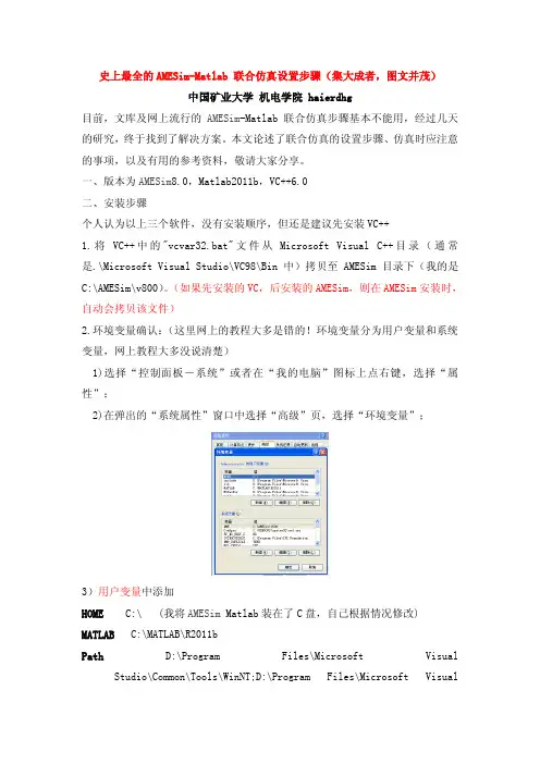
史上最全的AMESim-Matlab 联合仿真设置步骤(集大成者,图文并茂)中国矿业大学机电学院 haierdhg目前,文库及网上流行的AMESim-Matlab 联合仿真步骤基本不能用,经过几天的研究,终于找到了解决方案。
本文论述了联合仿真的设置步骤、仿真时应注意的事项,以及有用的参考资料,敬请大家分享。
一、版本为AMESim8.0,Matlab2011b,VC++6.0二、安装步骤个人认为以上三个软件,没有安装顺序,但还是建议先安装VC++1.将VC++中的"vcvar32.bat"文件从Microsoft Visual C++目录(通常是.\Microsoft Visual Studio\VC98\Bin中)拷贝至AMESim目录下(我的是C:\AMESim\v800)。
(如果先安装的VC,后安装的AMESim,则在AMESim安装时,自动会拷贝该文件)2.环境变量确认:(这里网上的教程大多是错的!环境变量分为用户变量和系统变量,网上教程大多没说清楚)1)选择“控制面板-系统”或者在“我的电脑”图标上点右键,选择“属性”;2)在弹出的“系统属性”窗口中选择“高级”页,选择“环境变量”;3)用户变量中添加HOME C:\ (我将AMESim Matlab装在了C盘,自己根据情况修改) MATLAB C:\MATLAB\R2011bPath D:\Program Files\Microsoft Visual Studio\Common\Tools\WinNT;D:\Program Files\Microsoft VisualStudio\Common\MSDev98\Bin;D:\Program Files\Microsoft Visual Studio\Common\Tools;D:\Program Files\Microsoft Visual Studio\VC98\bin4)在系统变量中添加AME C:\AMESim\v800 (这个一般都有的,不需要自己添加);Path D:\Program Files\Microsoft Visual Studio;C:\AMESim\v800;C:\AMESim\v800\win32;C:\AMESim\v800\sys\mingw32\bin;C:\AMESim\v800\sys\mpich\mpd\bin;C:\AMESim\v800\sys\cgns;%SystemRoot%\system32;%SystemRoot%;%SystemRoot%\System32\Wbem;C:\MATLAB\R2011b\bin\win32;C:\WINDOWS\system32;C:\WINNT (该处很重要一定要添加,而且一定要包含C:\WINDOWS\system32,不然会有引起很多错误)3.确认是否在AMESim中选择VC作为编译器。
四足机器人动力学建模:拉格朗日动力学引言在机器人领域中,四足机器人是一种常见的机器人类型。
它们具有四条腿和能够模拟和模仿动物行走的能力。
为了实现自主步行和平稳运动,我们需要对四足机器人的动力学进行建模和分析。
本文将介绍使用拉格朗日动力学方法对四足机器人进行建模的过程和步骤。
拉格朗日动力学简介拉格朗日动力学是一种描述系统动力学行为的方法。
它基于拉格朗日原理,通过最小化系统的运动方程,求解系统中的广义坐标和约束力。
在机器人动力学中,拉格朗日动力学方法被广泛应用于建模和控制。
四足机器人动力学建模步态与坐标系在进行四足机器人动力学建模之前,首先需要确定机器人的步态和坐标系。
通常,四足机器人的步态可以分为步行和跑步两种模式。
对于步行模式,机器人的步态可以简化为前后左右四个联系稳定的点。
在这种情况下,机器人的坐标系可以选择为正前方为x轴正方向,右侧为y轴正方向,地面为z轴正方向。
运动学分析在进行动力学建模之前,需要进行机器人的运动学分析。
运动学分析可以得到机器人各个关节的位置、速度和加速度信息。
这些信息对于后续的动力学建模非常重要。
动力学建模操作要素在进行动力学建模之前,需要确定机器人系统的操作要素。
这些要素包括机器人的质量、惯性、关节约束等。
通过对这些要素的分析和建模,可以得到机器人的整体动力学方程。
拉格朗日方程拉格朗日动力学方法使用拉格朗日方程来描述系统的运动方程。
拉格朗日方程可以通过系统的动能和势能表达式得到。
对于四足机器人,为了简化模型,通常可以假设机器人为刚体,并且忽略其柔软特性。
拉格朗日方程的形式如下:L = T - V其中,L为拉格朗日函数,T为系统的动能,V为系统的势能。
动力学模拟通过对拉格朗日方程进行求解,可以得到系统的运动方程。
为了模拟机器人的动力学行为,可以使用数值方法进行迭代求解。
常见的数值方法有欧拉法和中点法等。
结论通过拉格朗日动力学方法进行建模,可以得到四足机器人的运动方程和动力学模拟。
基于ADAMS软件的小型机器人设计与仿真刘伟达;曾凯;张皓天【摘要】应用SolidWorks软件建立小型机器人的三维模型,采用拉格朗日法建立其动力学模型,简化三维模型后导入ADAMS软件.在ADAMS软件中设置零件材料属性,添加系统各部位的约束、摩擦、运动、载荷,得到4s内各关节角速度和角加速度随时间的变化曲线,以及末端执行机构的位移和速度变化曲线.仿真结果表明,所建立的驱动函数符合小型机器人的实际运行情况,小型机器人在工作中无大抖动,运行较平稳,各项运行参数符合设计要求.【期刊名称】《机械制造》【年(卷),期】2018(056)012【总页数】4页(P39-42)【关键词】小型机器人;计算机;设计;仿真【作者】刘伟达;曾凯;张皓天【作者单位】潍柴动力股份有限公司山东潍坊 261061;昆明理工大学机电工程学院昆明 650500;昆明理工大学机电工程学院昆明 650500【正文语种】中文【中图分类】TH1221 研究背景机器人对恶劣环境具有极好的适应性,并且可以代替工人完成一些高危和重复性的工作。
小型化是机器人发展的一个趋势[1]。
在工业生产中,一般将负载小于20 kg的机器人称为小型机器人。
与传统大负载工业机器人相比,小型机器人具有体积小、能耗少、灵活性强、效率高、定位精准等优势。
随着工业商品的小型化,小型机器人的需求日益增加,因此小型机器人具有很高的市场需求和开发价值[2]。
美国MIT人工智能实验室开发的WAM轻小型机器人[3-4],有七个旋转关节,空间运动范围为1 m。
日本的Micro5五关节轻型机器人,可根据实际工况改为六关节机器人[5],这一机器人使用超声电机作为驱动,减小了自重,有较高的负载与自身质量比。
国内机器人的开发大多集中在服务与救援领域,如哈尔滨工业大学开发的服务型机器人、沈阳自动化研究所开发的灵蜥机器人等[6-7]。
笔者基于ADAMS软件,对小型机器人进行设计和仿真。
2 动力学理论在机器人的设计与控制中,动力学分析是一个很重要的过程,目的是确立刚体运动和力之间的关系。
四足机器人步态分类
四足机器人的步态分类通常有以下几种:
1. 走行步态(Trotting):四足机器人的前后腿交替移动,类似于马匹的跑步方式。
这种步态具有较高的稳定性和速度。
2. 跳跃步态(Bounding):四足机器人通过同时腾空两只相对的腿来前进。
这种步态可以使机器人快速移动,并且具有较好的适应不平地形的能力。
3. 跑步步态(Galloping):四足机器人的前后腿交替移动,但在某些阶段会同时腾空两只相对的腿。
这种步态适用于高速奔跑,但在稳定性上稍逊于走行步态。
4. 攀爬步态(Climbing):四足机器人使用四只腿同时爬行,适用于攀爬垂直或倾斜的表面。
这种步态通常需要机器人具备较强的抓握能力。
以上仅是四足机器人步态分类的一些常见示例,实际上还存在其他更多的步态。
不同的步态适用于不同的应用场景,选择合适的步态可以使机器人在特定环境中更加高效和稳定地移动。
四足机器人控制系统的简单设计摘要:近年来四足机器人开始走进人们视野。
四足机器人是一个庞大的系统,而控制系统是其中最重要的系统之一。
一个良好及鲁棒性强的控制系统是四足机器人系统功能最大化的基础之一。
而要达到该期望的控制系统也往往更复杂。
本研究基于机器人运动学与图像处理技术,研究设计了一个四足机器人简单控制系统,旨在能对四足机器人进行初步控制验证,作为复杂控制系统开发的基础。
关键词:四足机器人;运动学控制;图像处理;1.项目意义四足机器人控制系统中往往采用动力学控制方法。
目前主流的控制方法中,MPC模型预测控制方法和WBC全身控制方法是非常常用的。
但采用该方法的控制系统复杂程度比较高,也往往需要较深的控制技术基础,不适合用于控制系统的前期验证。
为了克服上述问题。
本研究基于机器人运动学、ROS机器人开源操作系统,搭建了一个能在世界坐标系下进行运动的简单控制系统,并使用物理样机进行了验证。
该系统也能应用于物理样机制作中的前期验证,提高机器人研发迭代速度。
2.研究内容2.1基于机器人运动学的控制算法机器人运动学算法是本控制系统的关键。
本文借助逆矩阵等数学工具,实现了一个四足机器人运动学算法。
基于该算法,机器人不仅能轻松实现四足着地时的姿态控制,还能实现在运动中对机器人的姿态控制。
当然实现动静状态下的姿态控制,也同时意味着机器人能在一定的躯干扰动(对姿态的影响)下,依然能保持躯干的稳定,实现机器人的稳定运动控制。
本系统使用ROS开源系统中的RVIZ 可视化工具进行可视化。
2.2地形构建系统机器人的地形构建系统可以提供四足机器人运动中需要的信息:1.利用地形数据修正摆动相足端的落足点高度,使得四足机器人的腿部能跨越障碍。
2.利用地形数据,可以通过预先解算出机器人运行到该地形的数据,并作为机器人的姿态控制量进行预先控制,这在机器人遇到一些大型障碍中非常有用。
故地形构建系统是非常重要的系统。
3.系统实现3.1 基于机器人运动学的控制算法四足机器人坐标系定义如图1所示,在初始状态中,世界坐标系与躯干坐标系处于同样位置。
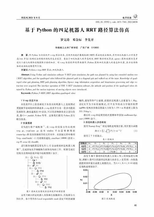
科技风2021年8月电子信息DOI:10.19392/ki.1671-7341.202124038基于Python的四足机器人RRT路径算法仿真罗文涛邓金标李先开华南理工大学广州学院广东广州510800摘要:用Python与仿真软件v-rep联合仿真,实现用快速扩展随机树(RRT)算法规划出路径,并用四足机器人以对角步态(hot步态)沿规划出的路径循线并走出迷宫。
囊括了四足机器人的步态规划、RRT路径规划算法、openca获取地图信息并进行二值化处理和边缘提取方面的知识。
对v-rep仿真软件的界面操作、Python获取四足机器人的姿态和位置、显示运动物体的运动轨迹都有所介绍。
关键词:Python;vrep;RRT算法;四足机器人Abstract:Using Python and sieulation soSuaro V-REP joint simulation,the path was planned by using fast extended random tree (RRT)algorithm,and the quadruped robot followed the planned path in a diagonal gait and walked out of the maze.Knowledge of quadruped robot gait planning,RRT path planning algorithm,Openca map information acquisition and binarization processing and edge extraction were acquired.The interfacc operation of THE V-REP simulation soSuaro,the attitude and position of the quadruped robot obtained by Python,and the motion trajectorc of moving objects were inUoduced.Keywords:Python;V-REP;RRT algorithm;quadruped robot1V-rap仿真平台在仿真平台上仿真相比于在真实的机器人上直接测试更能够节省时间和科研成本,vrep仿真平台是一款多功能的仿真软件,拥有逼真的3D渲染,可以用多种脚本语言进行仿真,像C++、maaab、Python等等。
基于Webots仿真软件的四足机器人建模和运动控制辛亚先;李彬;洪真【摘要】运用计算机进行机器人仿真,首先对四足机器人模型的各项参数进行设定,对各部分关系进行分析;在此基础上利用Webots 8.3仿真平台构建机器人的3D模型、分析了机器人控制原理,以及如何创建和添加控制器。
【期刊名称】《齐鲁工业大学学报:自然科学版》【年(卷),期】2016(030)002【总页数】7页(P45-51)【关键词】Webots软件四足机器人建模方法控制方法【作者】辛亚先;李彬;洪真【作者单位】齐鲁工业大学理学院,山东济南250353【正文语种】中文【中图分类】TP242仿真技术是机器人理论研究中的一个重要组成部分。
利用各种仿真和离线编程系统对机器人的性能和特点进行试验和改进,首先,避免了不恰当的控制策略对昂贵的物理样机的损坏;其次,其成果为物理样机制造提供了有效的理论依据和方法指导。
因此,机器人仿真系统对于机器人理论和实践有着显而易见的价值和意义。
目前,机器人仿真软件众多,其中,国外的许多仿真软件比较成熟,国内很多此类研究都是在已有软件的基础上进行的二次开发[1]。
国外众多成熟的仿真软件,各自有其不同的功能侧重,因此,可以根据仿真目标的不同,选择合适的仿真软件。
例如,ADAMS仿真软件其优势在于可以对复杂机械系统进行仿真,一般用来分析和比较多种不同参数的方案,给出优化的工作性能[2];Microsoft Robotics Studio 机器人仿真平台由微软公司研发,它的功能丰富而且扩展性强,用户可以使用图形化的数据流驱动逻辑运算[3];Open Dynamics Engine(ODE)是由Russell Smith最初研发的开源免费物理引擎,它包含刚体动力学模拟引擎和碰撞检测引擎两部分,让用户可以更方便的使用各种功能实现对物理环境的仿真[4];Robotbuilder是由Rodenbaugh 开发的一款机器人动力学仿真软件,可适用于windows系统,其包含构建模式、仿真模式和回放模式,已被俄亥俄州立大学用于机器人教学课程[5];ROBCAD仿真软件侧重于图形的设计和运算,可输出机器人任一零部件的尺寸[6]。
(此文档为word格式,下载后您可任意编辑修改!)摘要四足机器人作为仿生机器人的一种,得到了广泛的研究。
行走机构和转弯机构是四足机器人最关键的部分,目前,行走机构的研究大多采用在腿机构的关节处安装伺服电机进行驱动,增加了机器人的重量和控制策略的难度。
并且,机器人本体大多是一个刚性整体,转弯机构研究不足。
为此,项目将四足机器人本体作为一个柔性整体,采用三维建模软件Pro/E4.0设计了四足机器人的机械系统,提出了一种新颖的凸轮控制驱动式行走机构,设计了一种腿机构以及相应的凸轮控制驱动机构,并初步设计了柔性转弯机构。
在此基础上,论文采用主从式控制方式设计了四足机器人的控制系统,重点讨论了以8051单片机为控制器的行走机构和转向机构的控制系统设计。
关键词:四足机器人;行走机构;凸轮驱动;控制系统;三维设计AbstractQuadruped robot as one of biomimetic robots, has been extensively studied. Travel agencies and institutions is a quadruped robot turning the key, At the present, servo motor is installed in the leg joints of the most travel agencies, increasing the weight of the robot and the difficulty of the control system strategy . And most of the robot is a rigid body as a whole, and the research of the turning institutions is not fully studied . For this purpose, the project will take four-legged robot whole body as a flexible rigid body, and three-dimensional modeling software Pro/E4.0 is used for designing quadruped robot mechanical systems, a new travel agency based on cam control drive is proposed , a kind of leg mechanism and control of the corresponding cam drive mechanism is designed, and a flexible turning institution is preliminary designed. Based on this work, thecontrol system of the robot was designed. Especially, control systems of the stepped mechanism and the wheel mechanism were analyzed detailed.Key words: quadruped robot; stepped mechanism; cam drive; control system ;three dimensional design;目录1.引言 (1)1.1机器人及其相关技术的发展 (1)1.2国内外四足行走机器人得研究概况 (2)1.3机器人学主要涉及的学科内容 (4)1.4课题简介 (5)2.机器人系统总体设计 (6)2.1机器人系统结构概述 (6)2.2四足机器人研发流程 (7)2.3四足机器人系统结构设计 (9)3.四足机器人机械系统的结构设计技术 (10)3.1机器人机械设计的内容及特点 (10)3.2机械结构总体设计 (11)3.3行走机构的研究 (13)3.4行走机构的设计计算 (19)3.5转弯机构的设计 (24)3.6腱机构 (28)3.7机器人的外形设计 (28)3.8驱动系统的设计 (29)4.控制系统的硬件设计 (35)4.1传感器 (35)4.2控制器 (36)4.3控制系统 (39)5.控制系统的软件设计 (42)5.1行走系统软件设计 (42)5.2转弯控制系统软件设计 (43)总结 (47)参考文献 (49)致谢 (51)凸轮控制驱动式的四足机器人系统设计1. 引言1.1机器人及其相关技术的发展自从人类制造出了一电子计算机为代表的各种信息处理和计算的工具,进一步拓展和延伸了人类大脑的功能。
0 引言目前,智能机器人领域的发展呈现多元化、智能化等趋势,机器人产业得到极大发展,各种可移动机器人陆续被研制出来协助人们的生产和生活,使用移动机器人替代人类在各领域工作的研究也吸引了诸多学者的关注 [1]。
按照移动机器人结构的不同,可将其分为轮式、腿式、履带式机器人等[2]。
面对较为复杂的路面,传统的依靠单一移动模式的机器人逐渐难以满足需求。
因此,复合式地面移动机器人成为重点研究热点[3]。
目前,轮腿式结构主要有3种,轮子安装在机器人腿的末端,轮腿步态转换依靠末端轮子的收放;轮子与机器人腿结构分开,轮腿步态转换依靠各机构独自运行[4];轮腿混合机构,该机构具有轮式与腿式机器人的部分特征,轮腿步态不严格区分。
这3种轮腿机器人结构提高了机器人在非结构特种环境下的运动性能。
轮腿式机器人兼具轮式机器人的快速性、平稳性以及腿式机器人的高越障性,可以随外界环境调整自己的运动姿态,已经成为移动机器人领域一个充满活力、具有挑战性的前沿发展方向[5]。
本文设计了一种多功能、可实现构型切换、可搭载末端夹取装置的轮腿式机器人,该轮腿机器人拥有4条肢体,每条肢体都是由关节模块和碳纤维连接板组成的三自由度机械腿,通过仿真和试验分析来验证其稳定性。
1 机器人机械结构设计1.1 躯体结构设计轮腿机器人躯体部分主要由碳纤维板和亚克力板构成,在机壳前端头部安装有双目相机,在后端装有躯体轮;躯体内部布置有电池组、上位机和下轮腿式机器人运动学分析及其步态规划陈耀轩1 周子尧1 王峥宇1 梅 杰1,2 陈 昆1,21武汉理工大学交通与物流工程学院 武汉 430063 2武汉理工大学智能制造与控制研究所 武汉 430063摘 要:文中提出了一种可实现构型切换的轮腿式机器人,能根据地形的不同切换为不同的构型,且前腿末端可与夹取装置相结合,能够通过变换姿态构型将前腿用作机械臂,通过配合前臂关节与末端夹取装置协调运动以实现远程代替人工进行作业的功能;对轮腿机器人在运动过程中进行单腿的正/逆运动学分析;对轮腿机器人进行了CPG步态规划和可操作性仿真分析。
2015年2月
第43卷第3期
机床与液压
MACHINE TOOL&HYDRAULICS
Feb.2015
Vo1.43 No.3
DOI:10.3969/j.issn.1001—3881.2015.03.015
基于ADAMS与MATLAB的四足机器人的trot步态联合仿真
王建明,赵彦,朱彦防,马宗利
(山东大学高效洁净机械制造教育部重点实验室,山东济南250061)
摘要:为节约设计成本,提高设计效率,对四足机器人进行仿真。采用Pr0/E建立四足机器人三维模型,将模型导入
至虚拟样机软件ADAMS中.建立四足机器人机械模型,并利用Matlab/Simulink工具箱建立控制系统。利用二者之间的接
口实现联合仿真,验证了设计方案的可行性。
关键词:四足机器人;trot步态;联合仿真
中图分类号:TP242 文献标志码:A 文章编号:1001—3881(2015)3-057—3
Coordinated Simulation of Trot Gait for Quadruped Robot
Based on ADAMS and MATLAB
WANG Jianming,ZHAO Yan,ZHU Yanfang,MA Zongli
(Key Laboratory of High—efficiency and Clean Mechanical Manufacture of Ministry of Education,
Shandong University,Jinan Shandong 250061,China)
Abstract:In order to reduce the cost and to improve the design efficiency,the simulation of the quadruped robot was made.
Pro/E was used to build the three dimensional(3一D)model of the robot,then it was put into the ADAMS software of virtual prototype
to build the mechanical system model,and Matlab/Simulink toolbox was used to build the control system.The interface between them
is used to do the coordinated simulation and to verify the feasibility of the design.
Keywords:Quadruped robot;Trot gait;Coordinated simulation
0前言
随着科技发展。在许多复杂环境,例如:在崎岖
的山路上、地震火灾现场,四足机器人可以发挥出相
当重要的作用。在四足机器人机构设计中,设计一制
造一试验,往往经过多次反复,才能确定最终设计的
产品。为避免实物制造成本较高,周期过长,借助
ADAMS和Matlab/Simulink联合仿真,验证步态规
划、结构设计合理性,为后来实物设计提供依据,从
而提高效率.减少设计成本。
1 四足机器人仿真流程
采用ADAMS和Matlab联合仿真模式『l ]。首先
在Pro/E中建立四足机器人三维模型,将模型导入至
ADAMS中.建立机械系统模型.之后在Matlab/Sim.
ulink中建立控制系统。由ADAMS提供四足机器人虚
拟样机的三维模型、运动学模型和动力学模型,由
Simalink提供步态控制,二者之间互相交换数据.实
现联合仿真。
2建立动力学模型 ,
文中采用内膝肘式四足机器人,这是由于内膝肘
式四足机器人运行较稳定。采用简化模型,即每条腿
有两个自由度,膝关节和髋关节处各有一个俯仰自由
度。首先在Pr0/E中建立四足机器人三维模型,另存
为Parasolid格式导入至ADAMS中。在转换过程中四
足机器人模型会失去质量、质心等参数,需要在AD-
AMS中重新定义。
模型(见图1)建好之后,对四足机器人添加约
束和驱动。每条腿拥有两个自由度分别为髋关节和膝
关节处各有一个俯仰自由度,腿部关节约束为旋转约
束。在约束上添加共8个驱动,这些驱动通过函数变
量与Matlab相连接,对机器人进行控制。足端与地
面接触部位设置接触力,接触力类型为刚体对刚体
(Solid to solid),并设置存在摩擦力,调节接触力参
数可以得到不同环境模拟。
收稿日期:2013—12—12
作者简介:王建明(1963一),博士,教授,从事有限元和四足机器人研究。E—mail:zlm03@126.com。
第3期 王建明等:基于ADAMS与MATLAB的四足机器人的trot步态联合仿真 ・59・
据曲线如图5、6所示。
言2
邑1
囊
1
棵
蓉
舍
索
R
稃
群
l
k m
时间,s
时同,0
图6左前腿髋关节驱动力矩
从图中可以看出:
(1)髋关节的力矩要大于膝关节驱动力矩,这
是由于髋关节运动时要带动膝关节运动。驱动力矩曲 线会出现突变并形成尖峰.产生不平衡力矩.会对四 足机器人的稳定性造成影响。 (2)支撑相的驱动力矩比摆动相的驱动力矩要 大得多,这是由于腿部处于支撑相时关节要承担部分 躯体负载。 (3)髋关节关节驱动力矩在支撑相时最大值基 本保持在250 N・m以下,膝关节驱动力矩最大值基 本在150 N・m以下,各个关节驱动力矩变化幅度平 稳,没有过大的力矩产生。 4.3步长对稳定性影响 为了对关节运动幅值进行优化。采用不同的关节 运动幅值进行对比。由于膝关节的控制函数采用的是 半波函数,它的运动并不影响四足机器人的步长,四 足机器人步长是由髋关节的运动决定的、因此只需改 变髋关节的运动幅值即可。髋关节幅值大小影响四足 机器人行走步长的大小,髋关节幅值越大,步长越大。 现在设定髋关节运动幅值分别为5.5。、6.5o、7.5。, 进行仿真,四足机器人质心运动曲线如图7—9所示。 时间/s 图7髋关节幅值5.5。时四足机器人质心运动曲线 图8髋关节幅值6.5。时四足机器人质心运动曲线 。0 蠢 一-。0 图9髋关节幅值7.5。时四足机器人质心运动曲线 比较各图中四足机器人质心在Y轴和z轴最大偏 移.分别为髋关节幅值5.5。时,位移为0.02 m、 0.09 m;幅值为6.5o时位移为0.02 m、0.15 m;幅 值为7.5。时位移为0.1 m、0.4 m。在幅值为7.5。时, 四足机器人运动开始不稳,出现侧翻趋势。由此可以
进行推断,髋关节幅值越大,四足机器人运动越不稳
定。对比分析,选择髋关节幅值为5.5。。
5结论
应用Matlab与ADAMS相结合的方式,对四足机
器人行走过程进行仿真.分析了机器人能够trot稳定
行走。通过运动学和动力学仿真分析,验证了机构设
计的合理性。为选择电机提供参考。仿真提高了设计
效率。
参考文献:
[1]史耀强,厉明勇,顿向明,等.双足机器人基于ADAMS与
Matlab的联合仿真[J].机械与电子,2008(1):45—47.
[2]王克琦,温效朔.基于ADMAS与MATLAB的合作机器
人的联合仿真[J].机电产品开发与创新,2005,18(6):
35-37.
[3]徐建柱,刁燕,罗华,等.基于Matlab和Adams的自平衡
机器人联合仿真[J].现代电子技术,2012,35(6):90-
92.
[4]楼敏.四足机器人的步态仿真研究[J].现代制造工程,
2009,31(1):29—32.
[5]何冬青,马培荪.四足机器人动态步行仿真及步行稳定
性分析[J].计算机仿真,2005,22(2):146—149.
[6]陈佳品,程君实,席裕庚,等.四足机器人对角小跑直线
步行的虚拟模型[J].上海交通大学学报,2001,35(12):
1771—1775