电气工程及其自动化专业小区配电设计毕业论文外文文献翻译及原文
- 格式:doc
- 大小:57.00 KB
- 文档页数:9
原文:A SPECIAL PROTECTION SCHEME FOR VOLTAGE STABILITYPREVENTIONTara Alzahawi Student Member, IEEE Mohindar S. Sachdev Life Fellow, IEEEG. Ramakrishna Member, IEEEPower System Research Group University of Saskatchewan Saskatoon, SK S7N5A9, CanadaAbstractVoltage instability is closely related to the maximum load-ability of a transmission network. The energy flows on the transmission system depend on the network topology, generation and loads, and on the availability of sources that can generate reactive power. One of the methods used for this purpose is the Voltage Instability Predictor (VIP). This relay measures voltages at a substation bus and currents in the circuit connected to the bus. From these measurements, it estimates the Thévenin’s equivalent of the network feeding the substation and the impedance of the load being supplied from the substation. This paper describes an extension to the VIP technique in which measurements from adjoining system buses and anticipated change of load are taken into consideration as well.Keywords: Maximum load ability; Voltage instability; VIP algorithm.1.IntroductionDeregulation has forced electric utilities to make better use of the available transmission facilities of their power system. This has resulted in increased power transfers, reduced transmission margins and diminished voltage security margins.To operate a power system with an adequate security margin, it isessential to estimate the maximum permissible loading of the system using information about the current operation point. The maximum loading of a system is not a fixed quantity but depends on various factors, such as network topology, availability of reactive power reserves and their location etc. Determining the maximum permissible loading, within the voltage stability limit, has become a very important issue in power system operation and planning studies. The conventional P-V or V- Q curves are usually used as a tool for assessing voltage stability and hence for finding the maximum loading at the verge of voltage collapse [1]. These curves are generated by running a large number of load flow cases using, conventional methods. While such procedures can be automated, they are time-consuming and do not readily provide information useful in gaining insight into the cause of stability problems [2].To overcome the above disadvantages several techniques have been proposed in the literature, such as bifurication theory [3], energy method[4], eigen value method [5], multiple load flow solutions method [6] etc.Reference [7] proposed a simple method, which does not require off-linesimulation and training. The Voltage Indicator Predictor (VIP) method in[7] is based on local measurements (voltage and current) and produces an estimate of the strength / weakness of the transmission system connected to the bus, and compares it with the local demand. The closer the local demand is to the estimated transmission capacity, the more imminent is the voltage instability. The main disadvantage of this method is in the estimation of the Thévenin’s equivalent, which is obtained from two measurements at different times. For a more exact estimation, one requires two different load measurements.This paper proposes an algorithm to improve the robustness of the VIP algorithm by including additional measurements from surrounding load buses and also taking into consideration local load changes at neighboring buses.2. Proposed MethodologyThe VIP algorithm proposed in this paper uses voltage and current measurements on the load buses and assumes that the impedance of interconnecting lines (12Z ,13Z ) are known, as shown in (Figure 1). The current flowing from the generator bus to the load bus is used to estimateThévenin’s equivalent for the system in that direction. Similarly the current flowing from other load bus (Figure 2) is used to estimate Thévenin’s equivalent from other direction. This results in following equations (Figure 3). Note that the current coming from the second load bus over the transmission line was kept out of estimation in original (VIP) algorithm.)()()(111112211111----=-+th th th L Z E Z V Z Z V [1] )()()(122112112122----=-+th th th L Z E Z V Z Z V [2] 1111111)()(E th th th I Z V Z E =--- [3] 2122122)()(E th th th I Z V Z E =--- [4] Where 1E I and 2E I are currents coming from Th évenin buses no.1 and2. Equation (1)-(4) can be combined into a matrix form:⎥⎥⎥⎥⎥⎦⎤⎢⎢⎢⎢⎢⎣⎡---++---++-------------121211111212112121-12111121111211000000th th th th th th L th th L Z Z Z Z Z Z Z Z Z Z Z Z Z Z *=⎥⎥⎥⎥⎦⎤⎢⎢⎢⎢⎣⎡2121th th E E V V ⎥⎥⎥⎥⎦⎤⎢⎢⎢⎢⎣⎡2100E E I I [5] Using the first 2 rows in the system Equations (1)-(4), the voltage on buses number 1 and 2 can be found as shown in Equation (6) below. From Equation (6) we can see that the voltage is a function of impedances. Note that the method assumes that all Thévenin’s parameters are constant at the time of estimation.⎥⎥⎦⎤⎢⎢⎣⎡⎥⎥⎦⎤⎢⎢⎣⎡++--++=⎥⎦⎤⎢⎣⎡-----------12211111121212112112112111121*th th th th th L th L Z E Z E Z Z Z Z Z Z Z Z V V [6] Where, 111-=L Z y 11212-=Z y and 122-=L Z yThe system equivalent seen from bus no.1 is shown in Figure 3. Figure 4(a) shows the relationship between load admittances (1y and 2y ) and voltage at bus no.1. Power delivered to bus no.1 is (1S ) and it is a function of (1L Z ,2L Z ).1211*L y V S = [7]Equation 7 is plotted in figure 4 (b) as a ‘landscape’ and themaximum loading point depends on where the system trajectory ‘goes over the hill’.Fig. 1. 3-Bus system connections Fig. 2. 1-Bus modelFig. 3. System equivalent as seen by the proposed VIP relay on bus #1 (2-bus model)(a)Voltage Profile (b) Power ProfileFig. 4. Voltage and power profiles for bus #12.1. On-Line Tracking of Thévenin’s ParametersThévenin’s parameters are the main factors that decide the maximum loading of the load bus and hence we can detect the voltage collapse. InE can be expressed by the following equation:Figure3,thI Z V E th load th +=[8]V and I are directly available from measurements at the local bus. Equation (8) can be expressed in the matrix form as shown below.⎥⎥⎥⎥⎦⎤⎢⎢⎢⎢⎣⎡--⎥⎥⎥⎥⎦⎤⎢⎢⎢⎢⎣⎡=⎥⎥⎥⎥⎦⎤⎢⎢⎢⎢⎣⎡000010000001)()(00..r i i r th th th th i r I I I I X R i E r E V V [9]B= A X [10] The unknown parameters can be estimated from the following equation: B A AX A T T =[11]Note that all of the above quantities are functions of time and are calculated on a sliding window of discrete data samples of finite, preferably short length. There are additional requirements to make the estimation feasible:• There must be a significant change in load impedance in the data window of at least two set of Measurements.• For small changes in Thévenin’s parameters within a particular data window, the algorithm can estimate properly but if a sudden large change occurs then the process of estimation is postponed until the next data window comes in.• The monitoring device based on the ab ove principle can be used to impose a limit on the loading at each bus, and sheds load when the limit is exceeded. It can also be used to enhance existing voltage controllers. Coordinated control can also be obtained if communication is available.Once we have the time sequence of voltage and current we can estimate unknowns by using parameter estimation algorithms, such as Ka lm an Filtering approach described [6].stability margin (VSM) due to impedances can be expressed as (Z VSM );where subscript z denotes the impedance.Therefore we have: Load thev Load Z Z Z Z VSM -=[12]The above equation assumes that both load impedances (1Z , 2Z ) are decreasing at a steady rate, so the power delivered to bus 1 will increase according to Equation (7). However once it reaches the point of collapse power starts to decrease again.Now assume that both loads are functions of time. The maximum critical loading point is then given by Equation(13): 011==dtds S Critical [13]Expressing voltage stability margin due to load apparent power as ( S VSM ), we have: CriticalLoad Critical S S S S VSM -= [14]Note that both Z VSM and S VSM are normalized quantities and their values decrease as the load increases.At the voltage collapse point, both the margins reduce to zero and the corresponding load is considered as the maximum permissible loading.Fig. 5. VIP algorithm2.2. Voltage Stability Margins and the Maximum Permissible LoadingSystem reaches the maximum load point when the condition:thev load Z Z =is satisfied (Figure5).Therefore the voltage stability boundary can be defined by a circle with a radius of the Th évenin ’s impedance. For normal operation the thev Z is smaller than load Z (i.e. it is outside the circle) and the system operates on the upper part (or the stable region) of a conventional P-V curve [2].However, when thev Z exceeds load Z the system operates on the lower part (or unstable region) of the P-V curve, indicating that voltage collapse has already occurred. At the maximum power point, the load impedance becomes same as the Th évenin ’s (thev L Z Z =). Therefore, for a given load impedance (load Z ), the difference between thev Z and load Z can be considered as a safety margin. Hence the voltage as given in an IEEE survey, which described (111) schemes from (17) different countries [8].Fig. 6. Load actions to prevent from voltage instability2.3. Advantages of the proposed VIP algorithmBy incorporating the measurements from other load buses (Figure 3),Z . The the proposed VIP algorithm achieves a more accurate value ofloadZ is used to track system changes.on-line tracking ofthevThe proposed improvements in the VIP algorithm will result in better control action for power system voltage stability enhancement. The control measures are normally shunt reactor disconnection, shunt capacitor connection, shunt VAR compensation by means of SVC’s and synchrouns condensers, starting of gas turbines, low priority load disconnection, and shedding of low-priority load [8]. Figure 6 shows the most commonly used remedial actions .3.ConclusionsAn improved Voltage Instability Predictor (VIP) algorithm for improving the voltage stability is proposed in this paper. The previous VIP method [7] used measurements only from the bus where the relay is connected. The new method uses measurements from other load buses as well. The voltage instability margin not only depends on the present state of the system but also on future changes.Therefore, the proposed algorithm uses an on-line tracking Thévenin’s equivalent for tracking the system trajectory. The algorithm is simple and easy to implement in a numerical relay. The information obtained by the relay can be used for load shedding activation at the bus or VAR compensation. In addition, the signal may be transmitted to the control centre,where coordinated system-wide control action can be undertaken.The algorithm is currently being investigated on an IEEE 30 bus system and results using the improved VIP algorithm will be reported in a future publication.References[1] M.H.Haque, “On line monitoring of maximum permissible loading of a power system within voltage stability limits”, IEE proc. Gener. Transms. Distrib.,Vol. 150, No. 1, PP. 107-112, January, 2003[2] V. Balamourougan, T.S. Sidhu and M.S. Sachdev, “Technique for online prediction of voltage collapse”, IEE Proc.Gener.Transm. Distrib., Vol.151, No. 4, PP. 453-460, July, 2004[3] C.A. Anizares, “On bifurcations voltage collapse and load modeling “IEEE Trans. Power System, Vol. 10, No. 1, PP. 512-522, February, 1995[4] T.J Overbye and S.J Demarco, “Improved Technique for Power System voltage stability assessment using energy methods“, IEEE Trans. Power Syst., Vol. 6, No. 4, PP. 1446-1452, November, 1991[5] P.A Smed Loof. T. Andersson, G. Hill and D.J,”Fast calculation of voltage stability index”, IEEE Trans. Power Syst. Vol. 7, No. 1, PP. 54-64, February, 1992 [6] K. Ohtsuka ,” An equivalent of multi- machine power system and its identification for on-line application to decentralized stabilizers”, IEEE Trans. Power Syst., Vol. 4 No. 2, PP. 687-693, May, 1989[7] Khoi Vu, Miroslav M Begovic, Damir Novosel, Murari Mohan Saha, “ Use of local Measurements to estimate voltage – stability margin “IEEE Trans. Power syst. Vol. 14, No. 3, PP. 1029-1035, August, 1999[8] G.Verbic and F. Gubina “Fast voltage-collapse line protection algorithm based on local phasors”, IEE Proc.Gener.Transm. Distrib., Vol. 150, No. 4, PP. 482-486, July, 2003译文:一种特殊的预防电压波动的保护方案塔拉阿里扎哈维学生会员,IEEE 摩亨达瑞S.萨凯戴维院士,IEEEG.罗摩克里希纳会员,IEEE (IEEE:美国电气和电子工程师协会)萨斯喀彻温省萨斯卡通大学的电力系统研究小组,SK S7N 5A9,加拿大摘要电压的波动与输电线路的最大负载能力密切相关。
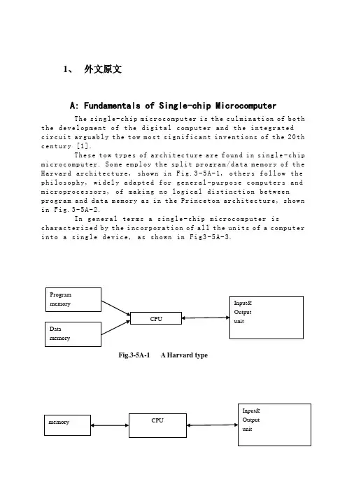
1、外文原文A: Fundamentals of Single-chip MicrocomputerTh e si ng le-c hi p m ic ro co mp ut er i s t he c ul mi na ti on of b oth t h e de ve lo pm en t o f t he d ig it al co m pu te r an d th e i n te gr at edc i rc ui t a rg ua bl y t h e to w m os t s ig ni f ic an t i nv en ti on s o f t he20th c e nt ur y [1].Th es e t ow ty pe s of ar ch it ec tu re a re fo un d i n s in g le-c hip m i cr oc om pu te r. So m e em pl oy t he spl i t pr og ra m/da ta m e mo ry o f th e H a rv ar d ar ch it ect u re, sh ow n in Fi g.3-5A-1, o th ers fo ll ow t he p h il os op hy, wi del y a da pt ed f or ge n er al-p ur po se co m pu te rs a nd m i cr op ro ce ss o r s, o f ma ki ng n o log i ca l di st in ct ion be tw ee np r og ra m an d d at a m e mo ry a s i n t he P r in ce to n ar ch ite c tu re, sh ow n i n F ig.3-5A-2.In g en er al te r ms a s in gl e-chi p m ic ro co mp ut er i sc h ar ac te ri zed b y t he i nc or po ra ti on of a ll t he un it s of a co mp ut er i n to a s in gl e d ev i ce, as s ho wn in Fi g3-5A-3.Fig.3-5A-1 A Harvard typeFig.3-5A-2. A conventional Princeton computerFig3-5A-3. Principal features of a microcomputerRead only memory (ROM).R OM i s us ua ll y f or th e p e rm an en t,n o n-vo la ti le s tor a ge o f an a pp lic a ti on s pr og ra m .M an ym i cr oc om pu te rs an d m ar e in te nd e d f or hi gh-v ol um e a p pl ic at io ns a n d he nc e t h e eco n om ic al m an uf act u re o f th e de vic e s re qu ir es t h at t he co nt en t s o f t he pr og ra m me m or y b e co mm it t ed pe rm a ne nt ly d u ri ng t he m an ufa c tu re o f ch ip s .Cl ea rl y, t hi s i m pl ie s ar i go ro us a pp ro ach to R OM c od e de ve l op me nt s in ce ch a ng es c an no t b e m ad e af te r m anu f a c tu re .Th is d ev e lo pm en t pr oc ess ma y in vo lv e e m ul at io n us in g a so ph is ti ca te d d e ve lo pm en t sy ste m w it h ah a rd wa re e mu la tio n c ap ab il it y as w el l as t he u se o f po we rf ul s o ft wa re t oo ls.So me m an uf act u re rs p ro vi de ad d it io na l RO M opt i on s byi n cl ud in g i n th eir r a n ge d ev ic es wi t h (or i nt en de d f o r u se w it h) u s er p ro gr am ma ble me mo ry. Th e sim p le st o f th es e i s u su al lyd e vi ce w hi ch c an o p er at e in a mi cro p ro ce ss or m od e b y u si ng s om e o f t he i np ut/o utp u t li ne s as a n a d dr es s an d da ta b us f ora c ce ss in g ex te rna l m em or y. T hi s t y pe o f de vi ce ca nb eh av ef u nc ti on al ly a s t h e si ng le ch ip mi cr oc om pu te r fro m w hi ch it is d e ri ve d al be it wi t h re st ri ct ed I/O a nd a m od if ied ex te rn alc i rc ui t. Th e u se o f th es ed ev ic es i s c om mo ne ve n i n pr od uc ti on c i rc ui ts wh er e t he vo lu me do es no t j us tif y t h e d ev el o pm en t c os ts o f c us to m o n-ch i p R OM[2];t he re c a n s ti ll be a s ig nif i ca nt sa vi ng i n I/O an d o th er c h ip s c om pa re d t o a co nv en ti on al mi c ro pr oc es so r b a se d ci rc ui t. Mo r e ex ac t re pl ace m en t fo r RO M dev i ce s ca n be o b ta in ed i n th e f o rm o f va ri an ts w it h 'p ig gy-b ack'E P RO M(Er as ab le pr o gr am ma bl e RO M )s oc ke ts o r d ev ic e s wi th EP RO M i n st ea d o f RO M 。
标准文档外文翻译院(系)专业班级姓名学号指导教师年月日Programmable designed for electro-pneumatic systemscontrollerJohn F.WakerlyThis project deals with the study of electro-pneumatic systems and the programmable controller that provides an effective and easy way to control the sequence of the pneumatic actuators movement and the states of pneumatic system. The project of a specific controller for pneumatic applications join the study of automation design and the control processing of pneumatic systems with the electronic design based on microcontrollers to implement the resources of the controller.1. IntroductionThe automation systems that use electro-pneumatic technology are formed mainly by three kinds of elements: actuators or motors, sensors or buttons and control elements like valves. Nowadays, most of the control elements used to execute the logic of the system were substituted by the Programmable Logic Controller (PLC). Sensors and switches are plugged as inputs and the direct control valves for the actuators are plugged as outputs. An internal program executes all the logic necessary to the sequence of the movements, simulates other components like counter, timer and control the status of the system.With the use of the PLC, the project wins agility, because it is possible to create and simulate the system as many times as needed. Therefore, time can be saved, risk of mistakes reduced and complexity can be increased using the same elements.A conventional PLC, that is possible to find on the market from many companies, offers many resources to control not only pneumatic systems, but all kinds of system that uses electrical components. The PLC can be very versatile and robust to be applied in many kinds of application in the industry or even security system and automation of buildings.Because of those characteristics, in some applications the PLC offers to much resources that are not even used to control the system, electro-pneumatic system is one of this kind of application. The use of PLC, especially for small size systems, can be very expensive for the automation project.An alternative in this case is to create a specific controller that can offer the exactly size and resources that the project needs [3, 4]. This can be made using microcontrollers as the base of this controller.The controller, based on microcontroller, can be very specific and adapted to only one kind of machine or it can work as a generic controller that can be programmed as a usual PLC and work with logic that can be changed. All these characteristics depend on what is needed and how much experience the designer has with developing an electronic circuit and firmware for microcontroller. But the main advantage of design the controller with the microcontroller is that the designer has the total knowledge of his controller, which makes it possible to control the size of the controller, change the complexity and the application of it. It means that the project gets more independence from other companies, but at the same time the responsibility of the control of the system stays at the designer hands2. Electro-pneumatic systemOn automation system one can find three basic components mentioned before, plus a logic circuit that controls the system. An adequate technique is needed to project the logic circuit and integrate all the necessary components to execute the sequence of movements properly.For a simple direct sequence of movement an intuitive method can be used [1, 5], but for indirect or more complex sequences the intuition can generate a very complicated circuit and signal mistakes. It is necessary to use another method that can save time of the project, makea clean circuit, can eliminate occasional signal overlapping and redundant circuits. The presented method is called step-by-step or algorithmic [1, 5], it is valid for pneumatic and electro-pneumatic systems and it was used as a base in this work.The method consists of designing the systems based on standard circuits made for each change on the state of the actuators, these changes are called steps.The first part is to design those kinds of standard circuits for each step, the next task is to link the standard circuits and the last part is to connect the control elements that receive signals from sensors, switches and the previous movements, and give the air or electricity to the supply lines of each step. In Figs. 1 and 2 the standard circuits are drawn for pneumatic and electro-pneumatic system [8]. It is possible to see the relations with the previous and the next steps.3. The method applied inside the controllerThe result of the method presented before is a sequence of movements of the actuator that is well defined by steps. It means that each change on the position of the actuators is a new state of the system and the transition between states is called step.The standard circuit described before helps the designer to define the states of the systems and to define the condition to each change betweenthe states. In the end of the design, the system is defined by a sequencethat never chances and states that have the inputs and the outputs well defined. The inputs are the condition for the transition and the outputs are the result of the transition.All the configuration of those steps stays inside of the microcontroller and is executed the same way it was designed. The sequences of strings are programmed inside the controller with 5 bytes; each string has the configuration of one step of the process. There are two bytes for the inputs, one byte for the outputs and two more for the other configurations and auxiliary functions of the step. After programming, this sequence of strings is saved inside of a non-volatile memory of the microcontroller, so they can be read and executed.The controller task is not to work in the same way as a conventional PLC, but the purpose of it is to be an example of a versatile controller that is design for an specific area. A conventional PLC process the control of the system using a cycle where it makes an image of the inputs, execute all the conditions defined by the configuration programmed inside, and then update the state of the outputs. This controller works in a different way, where it read the configuration of the step, wait the condition of inputs to be satisfied, then update the state or the outputs and after that jump to the next step and start the process again.It can generate some limitations, as the fact that this controller cannot execute, inside the program, movements that must be repeated for some time, but this problem can be solved with some external logic components. Another limitation is that the controller cannot be applied on systems that have no sequence. These limitations are a characteristic of the system that must be analyzed for each application.4. Characteristics of the controllerThe controller is based on the MICROCHIP microcontroller PIC16F877 [6,7] with 40 pins, and it has all the resources needed for thisproject .It has enough pins for all the components, serial communication implemented in circuit, EEPROM memory to save all the configuration of the system and the sequence of steps. For the execution of the main program, it offers complete resources as timers and interruptions.The list of resources of the controller was created to explore all the capacity of the microcontroller to make it as complete as possible. During the step, the program chooses how to use the resources reading the configuration string of the step. This string has two bytes for digital inputs, one used as a mask and the other one used as a value expected. One byte is used to configure the outputs value. One bytes more is used for the internal timer , the analog input or time-out. The EEPROM memory inside is 256 bytes length that is enough to save the string of the steps, with this characteristic it is possible to save between 48 steps (Table 1).The controller (Fig.3) has also a display and some buttons that are used with an interactive menu to program the sequence of steps and other configurations.4.1. Interaction componentsFor the real application the controller must have some elements to interact with the final user and to offer a complete monitoring of the system resources that are available to the designer while creating the logic control of the pneumatic system (Fig.3):•Interactive mode of work; function available on the main program for didactic purposes, the user gives the signal to execute the step. •LCD display, which shows the status of the system, values of inputs, outputs, timer and statistics of the sequence execution.•Beep to give important alerts, stop, start and emergency.• Leds to show power on and others to show the state of inputs and outputs.4.2. SecurityTo make the final application works property, a correct configuration to execute the steps in the right way is needed, but more then that itmust offer solutions in case of bad functioning or problems in the execution of the sequence. The controller offers the possibility to configure two internal virtual circuits that work in parallel to the principal. These two circuits can be used as emergency or reset buttons and can return the system to a certain state at any time [2]. There are two inputs that work with interruption to get an immediate access to these functions. It is possible to configure the position, the buttons and the value of time-out of the system.4.3. User interfaceThe sequence of strings can be programmed using the interface elements of the controller. A Computer interface can also be used to generate the user program easily. With a good documentation the final user can use the interface to configure the strings of bytes that define the steps of the sequence. But it is possible to create a program with visual resources that works as a translator to the user, it changes his work to the values that the controller understands.To implement the communication between the computer interface and the controller a simple protocol with check sum and number of bytes is the minimum requirements to guarantee the integrity of the data.4.4. FirmwareThe main loop works by reading the strings of the steps from the EEPROM memory that has all the information about the steps.In each step, the status of the system is saved on the memory and it is shown on the display too. Depending of the user configuration, it can use the interruption to work with the emergency circuit or time-out to keep the system safety. In Fig.4,a block diagram of micro controller main program is presented.5. Example of electro-pneumatic systemThe system is not a representation of a specific machine, but it is made with some common movements and components found in a real one. The system is composed of four actuators. The actuators A, B and C are double acting and D-single acting. Actuator A advances and stays in specified position till the end of the cycle, it could work fixing an object to the next action for example (Fig. 5) , it is the first step. When A reaches the end position, actuator C starts his work together with B, making as many cycles as possible during the advancing of B. It depends on how fastactuator B is advancing; the speed is regulated by a flowing control valve. It was the second step. B and C are examples of actuators working together, while B pushes an object slowly, C repeats its work for some time.When B reaches the final position, C stops immediately its cycle and comes back to the initial position. The actuator D is a single acting one with spring return and works together with the back of C, it is the third step. D works making very fast forward and backward movement, just one time. Its backward movement is the fourth step. D could be a tool to make a hole on the object.When D reaches the initial position, A and B return too, it is the fifth step.Fig. 6 shows the first part of the designing process where all the movements of each step should be defined [2]. (A+) means that the actuator A moves to the advanced position and (A−) to the initial position. The movements that happen at the same time are joined together in the same step. The system has five steps.These two representations of the system (Figs. 5 and 6) together are enough to describe correctly all the sequence. With them is possible to design the whole control circuit with the necessary logic components. But till this time, it is not a complete system, because it is missing some auxiliary elements that are not included in this draws because they work in parallel with the main sequence.These auxiliary elements give more function to the circuit and are very important to the final application; the most important of them is the parallel circuit linked with all the others steps. That circuit should be able to stop the sequence at any time and change the state of the actuators to a specific position. This kind of circuit can be used as a reset or emergency buttons.The next Figs. 7 and 8 show the result of using the method without the controller. These pictures are the electric diagram of the control circuit of the example, including sensors, buttons and the coils of the electrical valves.The auxiliary elements are included, like the automatic/manual switcher that permit a continuous work and the two start buttons that make the operator of a machine use their two hands to start the process, reducing the risk of accidents.6. Changing the example to a user programIn the previous chapter, the electro-pneumatic circuits were presented, used to begin the study of the requires to control a system that work with steps and must offer all the functional elements to be used in a real application. But, as explained above, using a PLC or this specific controller, the control becomes easier and the complexity can be increasealso.Table 2 shows a resume of the elements that are necessary to control the presented example.With the time diagram, the step sequence and the elements of the system described in Table 2 and Figs. 5 and 6 it is possible to create the configuration of the steps that can be sent to the controller (Tables 3 and 4).While using a conventional PLC, the user should pay attention to the logic of the circuit when drawing the electric diagram on the interface (Figs. 7 and 8), using the programmable controller, described in this work, the user must know only the concept o f the method and program only the configuration of each step.It means that, with a conventional PLC, the user must draw the relationbetween the lines and the draw makes it hard to differentiate the steps of the sequence. Normally, one needs to execute a simulation on the interface to find mistakes on the logicThe new programming allows that the configuration of the steps be separated, like described by the method. The sequence is defined by itself and the steps are described only by the inputs and outputs for each step.The structure of the configuration follows the order:1-byte: features of the step;2-byte: mask for the inputs;3-byte: value expected on the inputs;4-byte: value for the outputs;5-byte: value for the extra function.Table 5 shows how the user program is saved inside the controller, this is the program that describes the control of the example shown before.The sequence can be defined by 25 bytes. These bytes can be dividedin five strings with 5 bytes each that define each step of the sequence (Figs. 9 and 10).7. ConclusionThe controller developed for this work (Fig. 11) shows that it is possible to create a very useful programmable controller based on microcontroller. External memories or external timers were not used in case to explore the resources that the microcontroller offers inside. Outside the microcontroller, there are only components to implement the outputs, inputs, analog input, display for the interface and the serial communication.Using only the internal memory, it is possible to control a pneumatic system that has a sequence with 48 steps if all the resources for all steps are used, but it is possible to reach sixty steps in the case of a simpler system.The programming of the controller does not use PLC languages, but a configuration that is simple and intuitive. With electro-pneumatic system, the programming follows the same technique that was used before to design the system, but here the designer work s directly with the states or steps of the system.With a very simple machine language the designer can define all the configuration of the step using four or five bytes. It depends only on his experience to use all the resources of the controller.The controller task is not to work in the same way as a commercial PLC but the purpose of it is to be an example of a versatile controller that is designed for a specific area. Because of that, it is not possible to say which one works better; the system made with microcontroller is an alternative that works in a simple way.应用于电气系统的可编程序控制器约翰 F.维克里此项目主要是研究电气系统以及简单有效的控制气流发动机的程序和气流系统的状态。

电气工程与自动化毕业论文中英文资料外文翻译The Transformer on load ﹠Introduction to DC MachinesIt has been shown that a primary input voltage 1V can be transformed to any desired open-circuit secondary voltage 2E by a suitable choice of turns ratio. 2E is available for circulating a load current impedance. For the moment, a lagging power factor will be considered. The secondary current and the resulting ampere-turns 22N I will change the flux, tending to demagnetize the core, reduce m Φ and with it 1E . Because the primary leakage impedance drop is so low, a small alteration to 1Ewill cause an appreciable increase of primary current from 0I to a new value of 1Iequal to ()()i jX R E V ++111/. The extra primary current and ampere-turns nearly cancel the whole of the secondary ampere-turns. This being so , the mutual flux suffers only a slight modification and requires practically the same net ampere-turns 10N I as on no load. The total primary ampere-turns are increased by an amount 22N I necessary to neutralize the same amount of secondary ampere-turns. In thevector equation , 102211N I N I N I =+; alternatively, 221011N I N I N I -=. At full load,the current 0I is only about 5% of the full-load current and so 1I is nearly equalto 122/N N I . Because in mind that 2121/N N E E =, the input kV A which is approximately 11I E is also approximately equal to the output kV A, 22I E .The physical current has increased, and with in the primary leakage flux towhich it is proportional. The total flux linking the primary ,111Φ=Φ+Φ=Φm p , isshown unchanged because the total back e.m.f.,(dt d N E /111Φ-)is still equal and opposite to 1V . However, there has been a redistribution of flux and the mutual component has fallen due to the increase of 1Φ with 1I . Although the change is small, the secondary demand could not be met without a mutual flux and e.m.f.alteration to permit primary current to change. The net flux s Φlinking thesecondary winding has been further reduced by the establishment of secondaryleakage flux due to 2I , and this opposes m Φ. Although m Φ and 2Φ are indicatedseparately , they combine to one resultant in the core which will be downwards at theinstant shown. Thus the secondary terminal voltage is reduced to dt d N V S /22Φ-=which can be considered in two components, i.e. dt d N dt d N V m //2222Φ-Φ-=orvectorially 2222I jX E V -=. As for the primary, 2Φ is responsible for a substantiallyconstant secondary leakage inductance222222/Λ=ΦN i N . It will be noticed that the primary leakage flux is responsible for part of the change in the secondary terminal voltage due to its effects on the mutual flux. The two leakage fluxes are closely related; 2Φ, for example, by its demagnetizing action on m Φ has caused the changes on the primary side which led to the establishment of primary leakage flux.If a low enough leading power factor is considered, the total secondary flux and the mutual flux are increased causing the secondary terminal voltage to rise with load. p Φ is unchanged in magnitude from the no load condition since, neglecting resistance, it still has to provide a total back e.m.f. equal to 1V . It is virtually the same as 11Φ, though now produced by the combined effect of primary and secondary ampere-turns. The mutual flux must still change with load to give a change of 1E and permit more primary current to flow. 1E has increased this time but due to the vector combination with 1V there is still an increase of primary current.Two more points should be made about the figures. Firstly, a unity turns ratio has been assumed for convenience so that '21E E =. Secondly, the physical picture is drawn for a different instant of time from the vector diagrams which show 0=Φm , if the horizontal axis is taken as usual, to be the zero time reference. There are instants in the cycle when primary leakage flux is zero, when the secondary leakage flux is zero, and when primary and secondary leakage flux is zero, and when primary and secondary leakage fluxes are in the same sense.The equivalent circuit already derived for the transformer with the secondary terminals open, can easily be extended to cover the loaded secondary by the addition of the secondary resistance and leakage reactance.Practically all transformers have a turns ratio different from unity although such an arrangement is sometimes employed for the purposes of electrically isolating one circuit from another operating at the same voltage. To explain the case where 21N N ≠ the reaction of the secondary will be viewed from the primary winding. The reaction is experienced only in terms of the magnetizing force due to the secondary ampere-turns. There is no way of detecting from the primary side whether 2I is large and 2N small or vice versa, it is the product of current and turns which causesthe reaction. Consequently, a secondary winding can be replaced by any number of different equivalent windings and load circuits which will give rise to an identical reaction on the primary .It is clearly convenient to change the secondary winding to an equivalent winding having the same number of turns 1N as the primary.With 2N changes to 1N , since the e.m.f.s are proportional to turns, 2212)/('E N N E = which is the same as 1E .For current, since the reaction ampere turns must be unchanged 1222'''N I N I = must be equal to 22N I .i.e. 2122)/(I N N I =.For impedance , since any secondary voltage V becomes V N N )/(21, and secondary current I becomes I N N )/(12, then any secondary impedance, including load impedance, must becomeI V N N I V /)/('/'221=. Consequently,22212)/('R N N R = and 22212)/('X N N X = . If the primary turns are taken as reference turns, the process is called referring to the primary side.There are a few checks which can be made to see if the procedure outlined is valid.For example, the copper loss in the referred secondary winding must be the same as in the original secondary otherwise the primary would have to supply a differentloss power. ''222R I must be equal to 222R I . )222122122/()/(N N R N N I •• does infact reduce to 222R I .Similarly the stored magnetic energy in the leakage field)2/1(2LI which is proportional to 22'X I will be found to check as ''22X I . The referred secondary 2212221222)/()/(''I E N N I N N E I E kVA =•==.The argument is sound, though at first it may have seemed suspect. In fact, if the actual secondary winding was removed physically from the core and replaced by the equivalent winding and load circuit designed to give the parameters 1N ,'2R ,'2X and '2I , measurements from the primary terminals would be unable to detect any difference in secondary ampere-turns, kVA demand or copper loss, under normal power frequency operation.There is no point in choosing any basis other than equal turns on primary andreferred secondary, but it is sometimes convenient to refer the primary to the secondary winding. In this case, if all the subscript 1’s are interchanged for the subscript 2’s, the necessary referring constants are easily found; e.g. 2'1R R ≈,21'X X ≈; similarly 1'2R R ≈ and 12'X X ≈.The equivalent circuit for the general case where 21N N ≠ except that m r hasbeen added to allow for iron loss and an ideal lossless transformation has been included before the secondary terminals to return '2V to 2V .All calculations of internal voltage and power losses are made before this ideal transformation is applied. The behaviour of a transformer as detected at both sets of terminals is the same as the behaviour detected at the corresponding terminals of this circuit when the appropriate parameters are inserted. The slightly different representation showing the coils 1N and 2N side by side with a core in between is only used for convenience. On the transformer itself, the coils are , of course , wound round the same core.Very little error is introduced if the magnetising branch is transferred to the primary terminals, but a few anomalies will arise. For example ,the current shown flowing through the primary impedance is no longer the whole of the primary current.The error is quite small since 0I is usually such a small fraction of 1I . Slightlydifferent answers may be obtained to a particular problem depending on whether or not allowance is made for this error. With this simplified circuit, the primary and referred secondary impedances can be added to give:221211)/(Re N N R R += and 221211)/(N N X X Xe +=It should be pointed out that the equivalent circuit as derived here is only valid for normal operation at power frequencies; capacitance effects must be taken into account whenever the rate of change of voltage would give rise to appreciablecapacitance currents, dt CdV I c /=. They are important at high voltages and atfrequencies much beyond 100 cycles/sec. A further point is not the only possible equivalent circuit even for power frequencies .An alternative , treating the transformer as a three-or four-terminal network, gives rise to a representation which is just as accurate and has some advantages for the circuit engineer who treats all devices as circuit elements with certain transfer properties. The circuit on this basiswould have a turns ratio having a phase shift as well as a magnitude change, and the impedances would not be the same as those of the windings. The circuit would not explain the phenomena within the device like the effects of saturation, so for an understanding of internal behaviour .There are two ways of looking at the equivalent circuit:(a) viewed from the primary as a sink but the referred load impedance connected across '2V ,or(b) viewed from the secondary as a source of constant voltage 1V with internal drops due to 1Re and 1Xe . The magnetizing branch is sometimes omitted in this representation and so the circuit reduces to a generator producing a constant voltage 1E (actually equal to 1V ) and having an internal impedance jX R + (actually equal to 11Re jXe +).In either case, the parameters could be referred to the secondary winding and this may save calculation time .The resistances and reactances can be obtained from two simple light load tests. Introduction to DC MachinesDC machines are characterized by their versatility. By means of various combination of shunt, series, and separately excited field windings they can be designed to display a wide variety of volt-ampere or speed-torque characteristics for both dynamic and steadystate operation. Because of the ease with which they can be controlled , systems of DC machines are often used in applications requiring a wide range of motor speeds or precise control of motor output.The essential features of a DC machine are shown schematically. The stator has salient poles and is excited by one or more field coils. The air-gap flux distribution created by the field winding is symmetrical about the centerline of the field poles. This axis is called the field axis or direct axis.As we know , the AC voltage generated in each rotating armature coil is converted to DC in the external armature terminals by means of a rotating commutator and stationary brushes to which the armature leads are connected. The commutator-brush combination forms a mechanical rectifier, resulting in a DCarmature voltage as well as an armature m.m.f. wave which is fixed in space. The brushes are located so that commutation occurs when the coil sides are in the neutral zone , midway between the field poles. The axis of the armature m.m.f. wave then in 90 electrical degrees from the axis of the field poles, i.e., in the quadrature axis. In the schematic representation the brushes are shown in quarature axis because this is the position of the coils to which they are connected. The armature m.m.f. wave then is along the brush axis as shown.. (The geometrical position of the brushes in an actual machine is approximately 90 electrical degrees from their position in the schematic diagram because of the shape of the end connections to the commutator.)The magnetic torque and the speed voltage appearing at the brushes are independent of the spatial waveform of the flux distribution; for convenience we shall continue to assume a sinusoidal flux-density wave in the air gap. The torque can then be found from the magnetic field viewpoint.The torque can be expressed in terms of the interaction of the direct-axis air-gapflux per pole d Φ and the space-fundamental component 1a F of the armature m.m.f.wave . With the brushes in the quadrature axis, the angle between these fields is 90 electrical degrees, and its sine equals unity. For a P pole machine 12)2(2a d F P T ϕπ=In which the minus sign has been dropped because the positive direction of thetorque can be determined from physical reasoning. The space fundamental 1a F ofthe sawtooth armature m.m.f. wave is 8/2π times its peak. Substitution in above equation then givesa d a a d a i K i m PC T ϕϕπ==2 Where a i =current in external armature circuit;a C =total number of conductors in armature winding;m =number of parallel paths through winding;Andm PC K aa π2=Is a constant fixed by the design of the winding.The rectified voltage generated in the armature has already been discussedbefore for an elementary single-coil armature. The effect of distributing the winding in several slots is shown in figure ,in which each of the rectified sine waves is the voltage generated in one of the coils, commutation taking place at the moment when the coil sides are in the neutral zone. The generated voltage as observed from the brushes is the sum of the rectified voltages of all the coils in series between brushesand is shown by the rippling line labeled a e in figure. With a dozen or socommutator segments per pole, the ripple becomes very small and the average generated voltage observed from the brushes equals the sum of the average values ofthe rectified coil voltages. The rectified voltage a e between brushes, known also asthe speed voltage, ism d a m d a a W K W m PC e ϕϕπ==2 Where a K is the design constant. The rectified voltage of a distributed winding has the same average value as that of a concentrated coil. The difference is that the ripple is greatly reduced.From the above equations, with all variable expressed in SI units:m a a Tw i e =This equation simply says that the instantaneous electric power associated with the speed voltage equals the instantaneous mechanical power associated with the magnetic torque , the direction of power flow being determined by whether the machine is acting as a motor or generator.The direct-axis air-gap flux is produced by the combined m.m.f. f f i N ∑ of the field windings, the flux-m.m.f. characteristic being the magnetization curve for the particular iron geometry of the machine. In the magnetization curve, it is assumed that the armature m.m.f. wave is perpendicular to the field axis. It will be necessary to reexamine this assumption later in this chapter, where the effects of saturation are investigated more thoroughly. Because the armature e.m.f. is proportional to flux times speed, it is usually more convenient to express the magnetization curve in termsof the armature e.m.f. 0a e at a constant speed 0m w . The voltage a e for a given fluxat any other speed m w is proportional to the speed,i.e. 00a m m a e w w e =Figure shows the magnetization curve with only one field winding excited. This curve can easily be obtained by test methods, no knowledge of any design details being required.Over a fairly wide range of excitation the reluctance of the iron is negligible compared with that of the air gap. In this region the flux is linearly proportional to the total m.m.f. of the field windings, the constant of proportionality being the direct-axis air-gap permeance.The outstanding advantages of DC machines arise from the wide variety of operating characteristics which can be obtained by selection of the method of excitation of the field windings. The field windings may be separately excited from an external DC source, or they may be self-excited; i.e., the machine may supply its own excitation. The method of excitation profoundly influences not only the steady-state characteristics, but also the dynamic behavior of the machine in control systems.The connection diagram of a separately excited generator is given. The required field current is a very small fraction of the rated armature current. A small amount of power in the field circuit may control a relatively large amount of power in the armature circuit; i.e., the generator is a power amplifier. Separately excited generators are often used in feedback control systems when control of the armature voltage over a wide range is required. The field windings of self-excited generators may be supplied in three different ways. The field may be connected in series with the armature, resulting in a shunt generator, or the field may be in two sections, one of which is connected in series and the other in shunt with the armature, resulting in a compound generator. With self-excited generators residual magnetism must be present in the machine iron to get the self-excitation process started.In the typical steady-state volt-ampere characteristics, constant-speed primemovers being assumed. The relation between the steady-state generated e.m.f. a Eand the terminal voltage t V isa a a t R I E V -=Where a I is the armature current output and a R is the armature circuitresistance. In a generator, a E is large than t V ; and the electromagnetic torque T is acountertorque opposing rotation.The terminal voltage of a separately excited generator decreases slightly with increase in the load current, principally because of the voltage drop in the armature resistance. The field current of a series generator is the same as the load current, so that the air-gap flux and hence the voltage vary widely with load. As a consequence, series generators are not often used. The voltage of shunt generators drops off somewhat with load. Compound generators are normally connected so that the m.m.f. of the series winding aids that of the shunt winding. The advantage is that through the action of the series winding the flux per pole can increase with load, resulting in a voltage output which is nearly constant. Usually, shunt winding contains many turns of comparatively heavy conductor because it must carry the full armature current of the machine. The voltage of both shunt and compound generators can be controlled over reasonable limits by means of rheostats in the shunt field. Any of the methods of excitation used for generators can also be used for motors. In the typical steady-state speed-torque characteristics, it is assumed that the motor terminals are supplied froma constant-voltage source. In a motor the relation between the e.m.f. a E generated inthe armature and the terminal voltage t V isa a a t R I E V +=Where a I is now the armature current input. The generated e.m.f. a E is nowsmaller than the terminal voltage t V , the armature current is in the oppositedirection to that in a motor, and the electromagnetic torque is in the direction to sustain rotation of the armature.In shunt and separately excited motors the field flux is nearly constant. Consequently, increased torque must be accompanied by a very nearly proportional increase in armature current and hence by a small decrease in counter e.m.f. to allow this increased current through the small armature resistance. Since counter e.m.f. is determined by flux and speed, the speed must drop slightly. Like the squirrel-cage induction motor ,the shunt motor is substantially a constant-speed motor having about 5 percent drop in speed from no load to full load. Starting torque and maximum torque are limited by the armature current that can be commutatedsuccessfully.An outstanding advantage of the shunt motor is ease of speed control. With a rheostat in the shunt-field circuit, the field current and flux per pole can be varied at will, and variation of flux causes the inverse variation of speed to maintain counter e.m.f. approximately equal to the impressed terminal voltage. A maximum speed range of about 4 or 5 to 1 can be obtained by this method, the limitation again being commutating conditions. By variation of the impressed armature voltage, very wide speed ranges can be obtained.In the series motor, increase in load is accompanied by increase in the armature current and m.m.f. and the stator field flux (provided the iron is not completely saturated). Because flux increases with load, speed must drop in order to maintain the balance between impressed voltage and counter e.m.f.; moreover, the increase in armature current caused by increased torque is smaller than in the shunt motor because of the increased flux. The series motor is therefore a varying-speed motor with a markedly drooping speed-load characteristic. For applications requiring heavy torque overloads, this characteristic is particularly advantageous because the corresponding power overloads are held to more reasonable values by the associated speed drops. Very favorable starting characteristics also result from the increase in flux with increased armature current.In the compound motor the series field may be connected either cumulatively, so that its.m.m.f.adds to that of the shunt field, or differentially, so that it opposes. The differential connection is very rarely used. A cumulatively compounded motor has speed-load characteristic intermediate between those of a shunt and a series motor, the drop of speed with load depending on the relative number of ampere-turns in the shunt and series fields. It does not have the disadvantage of very high light-load speed associated with a series motor, but it retains to a considerable degree the advantages of series excitation.The application advantages of DC machines lie in the variety of performance characteristics offered by the possibilities of shunt, series, and compound excitation. Some of these characteristics have been touched upon briefly in this article. Stillgreater possibilities exist if additional sets of brushes are added so that other voltages can be obtained from the commutator. Thus the versatility of DC machine systems and their adaptability to control, both manual and automatic, are their outstanding features.中文翻译负载运行的变压器及直流电机导论通过选择合适的匝数比,一次侧输入电压1V 可任意转换成所希望的二次侧开路电压2E 。
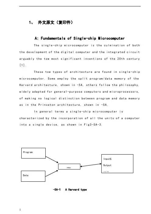
1、外文原文(复印件)A: Fundamentals of Single-chip MicrocomputerTh e si ng le-ch i p mi cr oc om pu ter is t he c ul mi nat i on o f bo th t h e d ev el op me nt o f th e d ig it al com p ut er an d t he int e gr at ed ci rc ui ta r gu ab ly th e t ow m os t s i gn if ic ant i nv en ti on s o f t h e 20t h c en tu ry[1].Th es e to w typ e s of a rc hi te ctu r e ar e fo un d i n s in gl e-ch ip m i cr oc om pu te r. So m e em pl oy t he sp l it p ro gr am/d ata me mo ry o f th e H a rv ar d ar ch it ect u re, sh ow n i n -5A, ot he rs fo ll ow th e ph i lo so ph y, w i de ly a da pt ed fo r g en er al-p ur pos e c om pu te rs an d m i cr op ro ce ss or s, o f m a ki ng no lo gi c al di st in ct io n b e tw ee n p ro gr am a n d da t a m em ory a s i n th e Pr in cet o n ar ch it ec tu re,sh ow n in-5A.In g en er al te r ms a s in gl e-chi p m ic ro co mp ut er i sc h ar ac te ri zed b y the i nc or po ra tio n of al l t he uni t s o f a co mp ut er i n to a s in gl e dev i ce, as s ho wn in Fi g3-5A-3.-5A-1 A Harvard type-5A. A conventional Princeton computerFig3-5A-3. Principal features of a microcomputerRead only memory (ROM).R OM i s u su al ly f or th e p er ma ne nt, n o n-vo la ti le s tor a ge o f an a pp lic a ti on s pr og ra m .M an ym i cr oc om pu te rs an d mi cr oc on tr ol le r s a re in t en de d fo r h ig h-v ol ume a p pl ic at io ns a nd h en ce t he e co nom i ca l ma nu fa ct ure of t he d ev ic es r e qu ir es t ha t the co nt en ts o f the pr og ra m me mo ry b e co mm it te dp e rm an en tl y d ur in g th e m an uf ac tu re o f c hi ps . Cl ear l y, th is im pl ie sa ri g or ou s a pp roa c h t o R OM co de d e ve lo pm en t s in ce c ha ng es ca nn otb e m ad e af te r man u fa ct ur e .T hi s d e ve lo pm en t pr oce s s ma y in vo lv e e m ul at io n us in g a s op hi st ic at ed deve lo pm en t sy st em w i th a ha rd wa re e m ul at io n ca pa bil i ty a s we ll a s th e u se of po we rf ul so ft wa re t oo ls.So me m an uf act u re rs p ro vi de ad d it io na l RO M opt i on s byi n cl ud in g i n th ei r ra ng e de vi ce s wi th (or i nt en de d fo r us e wi th) u s er pr og ra mm ab le m em or y. Th e s im p le st of th es e i s us ua ll y d ev ice w h ic h ca n op er ate in a m ic ro pr oce s so r mo de b y usi n g so me o f th e i n pu t/ou tp ut li ne s as a n ad dr es s an d da ta b us f or acc e ss in g e xt er na l m e mo ry. T hi s t ype o f d ev ic e c an b e ha ve fu nc ti on al l y a s t he si ng le c h ip mi cr oc om pu te r fr om wh ic h i t i s de ri ve d a lb eit w it h r es tr ic ted I/O an d a mo di fie d e xt er na l ci rcu i t. T he u se o f t h es e RO Ml es sd e vi ce s is c om mo n e ve n in p ro du ct io n c ir cu it s wh er e t he v ol um e do es n o t ju st if y th e d e ve lo pm en t co sts of c us to m on-ch i p RO M[2];t he re c a n st il l b e a si g ni fi ca nt s a vi ng in I/O a nd ot he r c hi ps co mp ar ed t o a c on ve nt io nal mi cr op ro ce ss or b as ed c ir cu it. M o re e xa ctr e pl ac em en t fo r RO M d ev ic es c an b e o bt ai ne d in t he f o rm o f va ri an ts w i th 'pi gg y-ba ck'EP RO M(Er as ab le p ro gr am ma bl e ROM)s oc ke ts o rd e vi ce s w it h EP ROM i ns te ad o f R OM 。
毕业设计(论文)外文参考资料及译文译文题目:Kangle community Power Of Distribution in Yandu Of yancheng盐城市盐都区康乐小区配电设计学生姓名:学号: 0804110437 专业:电气工程及其自动化所在学院:机电工程学院指导教师:职称:讲师2012 年 3 月 3日Power Of community Distribution To DesignABSTRACT:The basic function of the electric power system is to transport the electric power towards customers. The l0kV electric distribution net is a key point that connects the power supply with the electricity using on the industry, business and daily-life. For the electric power, allcostumers expect to pay the lowest price for the highest reliability, but don't consider that it's self-contradictory in the co-existence of economy and reliable.To improve the reliability of the power supply network, we must increase the investment cost of the network construction But, if the cost that improve the reliability of the network construction, but the investment on this kind of construction would be worthless if the reducing loss is on the power-off is less than the increasing investment on improving the reliability .Thus we find out a balance point to make the most economic,between the investment and the loss by calculating the investment on power net and the loss brought from power-off.KEYWORDS:power supply and distribution, power distribution reliability,reactive compensation, load distributionThe revolution of electric power system has brought a new big round construction,which is pushing the greater revolution of electric power technique along with the application of new technique and advanced equipment. Especially, the combination of the information technique and electric power technique, to great ex- tent, has improved reliability on electric quality and electric supply. The technical development decreases the cost on electric construction and drives innovation of electric network. On the basis of national and internatio- nal advanced electric knowledge, the dissertation introduces the research hotspot for present electric power sy- etem as following.Firstly, This dissertation introduces the building condition of distribution automation(DA), and brings forward two typical construction modes on DA construction, integrative mode and fission mode .It emphasize the DA structure under the condition of the fission mode and presents the system configuration, the main station scheme, the feeder scheme, the optimized communication scheme etc., which is for DA research reference.Secondly, as for the (DA) trouble measurement, position, isolation and resume, This dissertation analyzes the changes of pressure and current for line problem, gets math equation by educing phase short circuit and problem position under the condition of single-phase and works out equation and several parameter s U& , s I& and e I& table on problem . It brings out optimized isolation and resume plan, realizes auto isolation and network reconstruction, reduces the power off range and time and improves the reliability of electric power supply through problem self- diagnoses and self-analysis. It also introduces software flow and use for problem judgement andsets a model on network reconstruction and computer flow.Thirdly, electricity system state is estimated to be one of the key techniques in DA realization. The dissertation recommends the resolvent of bad measurement data and structure mistake on the ground of describing state estimate way. It also advances a practical test and judging way on topology mistake in state estimate about bad data test and abnormity in state estimate as well as the problem and effect on bad data from state measure to state estimate .As for real time monitor and control problem, the dissertation introduces a new way to solve them by electricity break and exceptional analysis, and the way has been tested in Weifang DA.Fourthly, about the difficulty for building the model of load forecasting, big parameter scatter limit and something concerned, the dissertation introduces some parameters, eg. weather factor, date type and social environment effect based on analysis of routine load forecasting and means. It presents the way for electricity load forecasting founded on neural network(ANN),which has been tested it’s validity by example and made to be good practical effect.Fifthly, concerning the lack of concordant wave on preve nting concordant wave and non-power compensation and non-continuity on compensation, there is a topology structure of PWM main circuit and nonpower theory on active filter the waves technique and builds flat proof on the ground of Saber Designer and proves to be practical. Meanwhile, it analyzes and designs the way of non-power need of electric network tre- nds and decreasing line loss combined with DA, which have been tested its objective economic benefit throu- gh counting example.Sixthly, not only do the dissertation design a way founded on the magrginal electric price fitted to our present national electric power market with regards to future trends of electric power market in China and fair trade under the government surveillance, that is group competitio n in short-term trade under the way of grouped price and quantity harmony, but also puts forward combination arithmetic, math model of trading plan and safty economical restriction. It can solve the original contradiction between medium and long term contract price and short term competitive price with improvement on competitive percentage and cut down the unfair income difference of electric factory, at the same time, it can optimize the electric limit for all electric factories and reduce the total purchase charge of electric power from burthen curve of whole electric market network.The distribution network is an important link among the power system. Its neutral grounding mode and operation connects security and stability of the power system directly. At the same time, the problem about neutral grounding is associated with national conditions, natural environment, device fabrication and operation. For example, the activity situation of the thunder and lightning, insulating structure and the peripheral interference will influence the choice of neutral groundingmode Conversely, neutral grounding mode affects design, operation, debugs and developing. Generally in the system higher in grade in the voltage, the insulating expenses account for more sizable proportion at the total price of the equipment. It is very remarkable to bring the economic benefits by reducing the insulating level. Usually such system adopt the neutral directly grounding and adopt the autoreclosing to guarantee power supply reliability. On the contrary, the system which is lower in the voltage adopts neutral none grounding to raise power supply reliability. So it is an important subject to make use of new- type earth device to apply to the distribution network under considering the situation in such factors of various fields as power supply reliability, safety factor, over-voltage factor, the choice of relay protection, investment cost, etc.The main work of this paper is to research and choice the neutral grounding mode of the l0kV distribution network. The neutral grounding mode of the l0kV network mainly adopts none grounding, grounding by arc suppressing coil, grounding by reactance grounding and directly grounding. The best grounding mode is confirmed through the technology comparison. It can help the network run in safety and limit the earth electric arc by using auto-tracking compensate device and using the line protection with the detection of the sensitive small ground current. The paper introduces and analyzes the characteristic of all kind of grounding modes about l0kV network at first. With the comparison with technological and economy, the conclusion is drawn that the improved arc suppressing coil grounding mode shows a very big development potential.Then, this paper researches and introduces some operation characteristics of the arc suppressing coil grounding mode of the l0kV distribution network. And then the paper put emphasis on how to extinguish the earth electric arc effectively by utilizing the resonance principle. This paper combines the development of domestic and international technology and innovative achievement, and introduces the computer earth protection and autotracking compensate device. It proves that the improved arc suppressing coil grounding mode have better operation characteristics in power supply reliability, personal security, security of equipment and interference of communication. The application of the arc suppressing coil grounding mode is also researched in this paper.Finally, the paper summarizes this topic research. As a result of the domination of the arc suppressing coil grounding mode, it should be more popularized and applied in the distribution network in the future.The way of thinking, project and conclusions in this thesis have effect on the research to choose the neutral grounding mode not only in I0kV distribution network but also in other power system..The basic function of the electric power system is to transport the electric power towards customers. The l0kV electric distribution net is a key point that connects the power supply withthe electricity using on the industry, business and daily-life. For the electric power, all costumers expect to pay the lowest price for the highest reliability, but don't consider that it's self-contradictory in the co-existence of economy and reliable. To improve the reliability of the power supply network, we must increase the investment cost of the network con- struction But, if the cost that improve the reliability of the network construction, but the investment on this kind of construction would be worthless if the reducing loss is on the power-off is less than the increasing investment on improving the reliability .Thus we find out a balance point to make the most economic, between the investment and the loss by calculating the investment on power net and the loss brought from power-off. The thesis analyses on the economic and the reliable of the various line modes, according to the characteristics various line modes existed in the electric distribution net in foshan..First, the thesis introduces as the different line modes in the l0kV electric distribution net and in some foreign countries. Making it clear tow to conduct analyzing on the line mode of the electric distribution net, and telling us how important and necessary that analyses are.Second, it turns to the necessity of calculating the number of optimization subsection, elaborating how it influences on the economy and reliability. Then by building up the calculation mode of the number of optimization subsection it introduces different power supply projects on the different line modes in brief. Third, it carries on the calculation and analyses towards the reliability and economy of the different line modes of electric distribution net, describing drafts according by the calculation. Then it makes analysis and discussion on the number of optimization subsection.At last, the article make conclusion on the economy and reliability of different line modes, as well as, its application situation. Accordion to the actual circumstance, the thesis puts forward the beneficial suggestion on the programming and construction of the l0kV electric distribution net in all areas in foshan. Providing the basic theories and beneficial guideline for the programming design of the lOkV electric distribution net and building up a solid net, reasonable layout, qualified safe and efficiently-worked electric distribution net.References[1] Wencheng Su. Factories power supply [M]. Machinery Industry Publishing House. 1999.9[2] Jiecai Liu. Factories power supply design guidance [M]. Machinery Industry Publishing House.1999.12[3] Power supply and distribution system design specifications[S].China plans Press. 1996[4] Low-voltage distribution design specifications [S].China plans Press.1996.6译文:小区配电设计摘要:电力系统的基本功能是向用户输送电能。
电气专业毕业设计英文文献电气专业毕业设计英文文献外文资料与中文翻译外文资料:Relay protection present situation anddevelopment一、Relay protection development present situationElectrical power system's swift development to the relay protection proposed unceasingly the new request, the electronic technology, the computer technology and communication's swift development unceasingly has infused the new vigor for the relay protection technology's development, therefore, the relay protection technology is advantageous, has completed the development 4 historical stage in 40 remaining years of time.After the founding of the nation, our country relay protection discipline, the relay protection design, the relay factory industry and the relay protection technical team grows out of nothing, has passed through the path which in about 10 year the advanced countries half century pass through. In the 50s, our country engineers and technicians creatively absorption, the digestion, have grasped the overseas advanced relay protection equipment performance and the movement technology [1], completed one to have the deep relay protection theory attainments and the rich service experience's relay protection technical team, and grew the instruction function to the national relay protection technical team's establishment. The Achengrelay factory introduction has digested at that time the overseas advanced relay technique of manufacture, has established our country own relay manufacturing industry.Therefore our country has completed the relay protection research, the design, the manufacture, the movement and the teaching complete system in the 60s. This is the mechanical and electrical -like relay protection prosperous time, was our country relay protection technology development has laid the solid foundation.From the late 50s, the transistor relay protection was starting to study. In the 60s to the 80s in is the time which the transistor relay protection vigorous development and widely uses. And the Tianjin University and the Nanjing Electric power Automation Plant cooperation research's 500kv transistor direction high frequency protection develops with the Nanjing Electric power Automation Research institute the transistor high frequency block system is away from the protection, moves on the Gezhou Dam 500 kv lines [2], finished the 500kv line protection to depend upon completely from the overseas import time.From the 70s, started based on the integration operational amplifier's integrated circuit protection to study. Has formed the complete series to the late 80s integrated circuit protection, substitutes for the transistor protection gradually. The development which, the production, the application protected to the early 90s integrated circuit were still in the dominant position, this was theintegrated circuit protection time. The integrated circuit power frequency change quantity direction which develops in this aspect Nanjing Electric power Automation Research institute high frequency protected the influential role [3], the Tianjin University and the Nanjing Electric power Automation Plant cooperation development's integrated circuit phase voltage compensation type direction high frequency protection alsomoved in many 220kv and on the 500kv line.Our country namely started the computer relay protection research from the late 70s [4], the institutions of higher learning and the scientific research courtyard institute forerunner's function. Huazhong University of Science and Technology, the Southeast University, the North China electric power institute, Xi'an Jiaotong University, the Tianjin University, Shanghai Jiaotong University, the Chongqing University and the Nanjing Electric power Automation Research institute one after another has developed the different principle, the different pattern microcomputer protective device. in 1984 the original North China electric power institute developed the transmission line microcomputer protective device first through the appraisal, and obtained the application in the system [5], has opened in our country relay protection history the new page, protected the promotion for the microcomputer to pave the way. In the main equipment protection aspect, the generator which the Southeast University and Huazhong University of Science and Technology develops loses magnetism protection, the generator protection and the generator? Bank of transformers protectionalso one after another in 1989, in 1994 through appraisal, investment movement. The Nanjing Electric power Automation Research institute develops microcomputer line protective device alsoin 1991 through appraisal. Tianjin University and Nanjing Electric power Automation Plant cooperation development microcomputer phase voltage compensation type direction high frequency protection, Xi'an Jiaotong University and Xuchang relay factory cooperation development positive sequence breakdown component direction high frequencyprotection also one after another in 1993, in 1996 through appraisal. Hence, the different principle, the different type's microcomputer line and the main equipment protect unique, provided one group of new generation performance for the electrical power system to be fine, the function was complete, operation reliable relay protection installment. Along with the microcomputer protective device's research, in microcomputer aspects and so on protection software, algorithm has also made many theory progresses. May say that started our country relay protection technology from the 90s to enter the time which the microcomputer protected.二、future development of Relay protectionThe future trend of relay protection technology is to computerization, networking is intelligent, protect, control, measure and data communication developing by integration. The principles of protection of electric power circuits are quite independent of the relay designs which may be applied. For example, if the current to an electriccircuit or a machine is greater than that which can be tolerated, it is necessary to take remedial action. The device for recognizing the condition and initiating corrective measures would be termed as an over-current relay regardless of the mechanists by whichthe function would be accomplished. Because the functions of electromechanical devices are easily described, their performance wills ever as a basis for presenting a description of relays and relay systemsin general.Relays must have the following characteristics: Reliability---The nature of the problem is that the relay may be idle for periods extending into years and then be required tooperatewith fast responds, as intended, the first time. The penalty for failure to operate properly may run into millions of dollars.Selectivity---The relay must not respond to abnormal, but harmless, system conditions such as switching transients or sudden changes in load.Sensitivity---The relay must not fail to operate, even in borderline situations, when operation was planned.Speed---The relay should make the decision to act as close to instantaneously as possible. If intentional time delay is available, it should be predictable and precisely adjustable.Instantaneous---The term means no intentional time delay.There are several possible ways to classify relays: by function, by construction, by application. Relays are one of two basic types of construction: electromagnetic or solid-state. The electromagnetic type relies on the development of electromagnetic forces on movable members,which provide switching action by physically opening or closing sets of contacts. The solid state variety provides switching action with no physical motion by changing the state of serially connected solid state component from no conducting to conducting(or vice versa). Electromagnetic relays are older and more widely used; solid state relays are more versatile, potentially more reliable, and fast.1)ComputerizationWith swift and violent development of computer hardware, computer protect hardware develop constantly even. The power system is improving to the demand that the computer protects constantly, besides basic function protected, should with trouble information of the large capacity and data the long-term parkingspace also, fast data processing function, strong communication capacity, network in order to share the whole system data , information , ability , network of resource with other protection , control device , dispatcher, high-level language programming ,etc.. This requires computer protector to have function which is equivalent to a pc machine. In computer is it develop initial stage to protect, is it make with one minicom relay protection install to imagine. Because the small-scale organism was accumulated greatly, with high costs at that time, dependability was bad, this imagined it was unrealistic . Now, exceed the minicomputer of those years greatly with computer protector size similar worker function , speed , memory capacity of accusing of machine, so make with complete sets of worker person who accuse of opportunity of relay protection already ripe, this will be one of the developing direction that a computer is protected . Tianjin university is it spend whom transformation act as continue the electric protector with computer protector structure self-same one worker person whoaccuse of to develop into already. The advantage of this kind of device is as follows, (1)it have functions of 486pc,it can meet to at present and it is various kinds of function demand where computerprotect future. (2)The size and structure are similar to present computer protector , the craft is superior, takes precautions against earthquakes , defends overheatedly and defending the electromagnetic ability of interfering strongly, can operate it in very abominable working environment , the cost is acceptable.(3)Adopting std bus or pc bus, hardware module , can select different module for use to different protection wantonly , it is flexible , easy to expand to dispose.It is an irreversible development trend to continue the computer , computerization of the electric protector. But to how better meet power system demand, how about raise the dependability of relay protection further, how make heavy economic benefits and social benefit, need carry on concrete deep research.2) NetworkedComputer network become the technological pillar of information age as message and data communication tool, made the mankind producing , basic change has taken place in the appearance with social life. It isinfluencing each industrial field deeply, has offered the powerful communication means for each industrial field too. Up till now, except that protect differentially and unite protecting vertically, all continue electric protector can only react that protect the electric quantity of installing office. The function of relay protection is only limited to excising the trouble component too , narrow the accident coverage. This mainly lack the powerful data communication means. Having already put forward the concept protected systematically abroad, this meant the safe automatics mainly at that time. Because the function of relay protection is not only limited to excising the trouble component and restriction accident coverage (this is primary task), the peace and steadiness that will be guaranteed the whole system run . This require each protect unit can share the whole operation and data , trouble of information of system, each protect unit and coincident floodgate device coordination on the basis of analysing the information and data, guarantee systematic peace and steadiness run . Obviously , realize the primary condition that system protect the whole system every protector of capitalequipment link with the computer network, namely the one that realized the computer protector is networked. This is totally possible under present technological condition .To general protecting systematically , realize the computer networking of the protector has a very great advantage too. It continue electric trouble not the less many in information not systematic can receiving protector ,for trouble nature , judgement and the trouble,trouble of position from measuring the less accurate. Protect to self-adaptation research of principle pass long time very already , make certain achievement too, but should really realize protecting the self-adaptation to the operation way of the system and trouble state, must obtain more system operating and trouble information , the computer that only realizes protecting is networked, could accomplish this . As to the thing that some protectors realize computer networking , can improve the dependability protected . Tianjin Sanxia vltrahigh voltage many return circuit bus bar , 500kv of power station , put forward one distributed principle that bus bar protected to future 1993 such as university, succeed in developing this kind of device tentatively. Principle its bus bar is it disperse several (with protect into bus bar back to way the same ) bus bar protect Entrance to protect traditional concentration type, disperse and install it in every return circuit is protected and rejected , each protect the unit to link with the computer network, each one protects the electric current amount that the unit only inputs a return circuit , after changing it into figure amount, convey to the protection units of other return circuits through the computer network, each protect the unit according to the electric current amount of this return circuit and electric current amount of other return circuits gotfrom computer network, carry on bus bar differential calculation that protect, if result of calculation prove bus bar trouble jump format return circuit circuit breaker only, isolate the bus bar of the trouble. At the time of the trouble outside the bus bar district , each protect the unit and calculate for movements of the external trouble. This kind protect principle by distributed bus barthat network realize with computer, bus bar protect principle have higher dependability than traditional concentration type. Because if one protect unit interfere or mistake in computation and when working up by mistake, can only jump format return circuit , can is it make bus bar to be whole of malignant accident that excise to cause wrong, this is very important to systematic pivot with supervoltage bus bar of hydropower station like SanxiaCan know computer protector networked to can raise and protect the performance and dependability greatly while being above-mentioned, this is an inexorable trend that a computer protects development 3) Protect , control , measure , data communication integratesOn terms that realize computerization of relay protection and networked, the protector is a high performance , multi-functional computer in fact, it is a intelligent terminal on the computer network of whole power system. It can obtain any information and data of operating and trouble of the power system from network , can convey network control centre or any terminal function , and can also finish the measurement , control , data communication function in there is no normal running of trouble cases, namely realize protecting ,controlling , measuring , data communication integrates.At present, for measurement, need that protects and controlling, all equipment of the outdoor transformer substation, two voltage, electric current of voltage transformer, circuit,etc. must with control cable guide to the top management room for instance. Lay control cable take a large amount of investment, make the very much complicated returncircuit 2 times in a large amount. But if above-mentioned protection, control, measure, data communication integrated computer device, install in to is it by the equipment , protect into voltage , electric current amount of equipment in device this after changing into the figure amount to protect outdoor transformer substation on the spot, send to the top management room through the computer network, can avoid a large number of controlcables . If use optic fibre as the transmission medium of the network , can avoid and interfere electromagnetically. The photocurrent mutual inductor of now (ota ) and photovoltage mutual inductor (otv ) have been already during the course of studying and testing, must get application in the power system in the future. In case of adopting ota and otv, namely should be putting and is being protected near the equipment.After the optical signals of ota and otv are input in the integrated device here and changes into an electric signal, what is on one hand uses as being protected calculation is judged ; As measurement amount on the other hand, send to the top management room through the network. Can to protect operation of equipment control order send this integrated device to through network from top management room, therefore the integrated device carries out the operation of the circuit breaker. The university of Tianjin put forward protecting,controlled , measured , communication integration in 1992, develop based on tms320c25 digital signal processor (dsp ) first protecting , control , measure , the integrated device of data communication.4)IntelligentIn recent years, if artificial intelligence technology neural network, hereditary algorithm, evolve plan , fuzzy logic ,etc. get application in power system all field, the research that is used in the field of relay protection has already begun too. Neural network one non-linear method that shine upon, a lot of difficult to list equation or difficult in order to the complicated non-linear question that is solved, use the method of the neural network to be very easily solved .For example the short circuit of crossing the resistance of courseof emergence is a non-linear problem in transmit electricity in the systematic electric potential angle of both sides of line and lay cases, it is very difficult to make discrimination , trouble of position while being correct for distance to protect, is it work up or is it work up to refuse by mistake to lead to the fact; If use neural network method, through a large number of trouble training of sample, so long as sample centralized to fully consider various kinds of situations, can differentiate correctly while any trouble takes place. Other if hereditary algorithm , is it is it have is it solve complicated abilityof problem to asking unique their too to plan to evolve. Artificial intelligence the being method proper to is it can make it solve speed to be fast not to ask to combine. Can predict , the artificial intelligence technology must get application in the field of relay protection, in order to solve the problem difficult to solvewith the routine method.中文翻译:继电保护的现状与发展一、继电保护发展现状电力系统的飞速发展对继电保护不断提出新的要求,电子技术、计算机技术与通信技术的飞速发展又为继电保护技术的发展不断地注入了新的活力,因此,继电保护技术得天独厚,在40余年的时间里完成了发展的4个历史阶段。
电气工程的外文文献(及翻译)文献一:Electric power consumption prediction model based on grey theory optimized by genetic algorithms本文介绍了一种基于混合灰色理论与遗传算法优化的电力消耗预测模型。
该模型使用时间序列数据来建立模型,并使用灰色理论来解决数据的不确定性问题。
通过遗传算法的优化,模型能够更好地预测电力消耗,并取得了优异的预测结果。
此模型可以在大规模电力网络中使用,并具有较高的可行性和可靠性。
文献二:Intelligent control for energy-efficient operation of electric motors本文研究了一种智能控制方法,用于电动机的节能运行。
该方法提供了一种更高效的控制策略,使电动机能够在不同负载条件下以较低的功率运行。
该智能控制使用模糊逻辑方法来确定最佳的控制参数,并使用遗传算法来优化参数。
实验结果表明,该智能控制方法可以显著降低电动机的能耗,节省电能。
文献三:Fault diagnosis system for power transformers based on dissolved gas analysis本文介绍了一种基于溶解气体分析的电力变压器故障诊断系统。
通过对变压器油中的气体样品进行分析,可以检测和诊断变压器内部存在的故障类型。
该系统使用人工神经网络模型来对气体分析数据进行处理和分类。
实验结果表明,该系统可以准确地检测和诊断变压器的故障,并有助于实现有效的维护和管理。
文献四:Power quality improvement using series active filter based on iterative learning control technique本文研究了一种基于迭代研究控制技术的串联有源滤波器用于电能质量改善的方法。
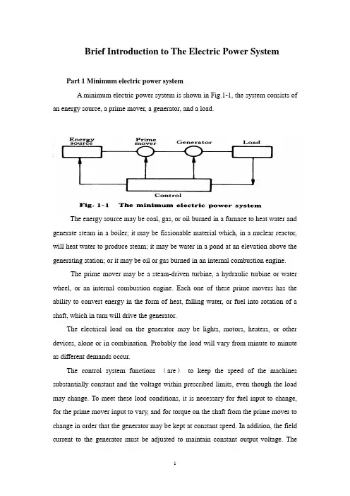
Brief Introduction to The Electric Power SystemPart 1 Minimum electric power systemA minimum electric power system is shown in Fig.1-1, the system consists of an energy source, a prime mover, a generator, and a load.The energy source may be coal, gas, or oil burned in a furnace to heat water and generate steam in a boiler; it may be fissionable material which, in a nuclear reactor, will heat water to produce steam; it may be water in a pond at an elevation above the generating station; or it may be oil or gas burned in an internal combustion engine.The prime mover may be a steam-driven turbine, a hydraulic turbine or water wheel, or an internal combustion engine. Each one of these prime movers has the ability to convert energy in the form of heat, falling water, or fuel into rotation of a shaft, which in turn will drive the generator.The electrical load on the generator may be lights, motors, heaters, or other devices, alone or in combination. Probably the load will vary from minute to minute as different demands occur.The control system functions (are)to keep the speed of the machines substantially constant and the voltage within prescribed limits, even though the load may change. To meet these load conditions, it is necessary for fuel input to change, for the prime mover input to vary, and for torque on the shaft from the prime mover to change in order that the generator may be kept at constant speed. In addition, the field current to the generator must be adjusted to maintain constant output voltage. Thecontrol system may include a man stationed in the power plant who watches a set of meters on the generator output terminals and makes the necessary adjustments manually. In a modern station, the control system is a servomechanism that senses generator-output conditions and automatically makes the necessary changes in energy input and field current to hold the electrical output within certain specifications..Part 2 More Complicated SystemsIn most situations the load is not directly connected to the generator terminals. More commonly the load is some distance from the generator, requiring a power line connecting them. It is desirable to keep the electric power supply at the load within specifications. However, the controls are near the generator, which may be in another building, perhaps several miles away.If the distance from the generator to the load is considerable, it may be desirable to install transformers at the generator and at the load end, and to transmit the power over a high-voltage line (Fig.1-2). For the same power, the higher-voltage line carries less current, has lower losses for the same wire size, and provides more stable voltage.In some cases an overhead line may be unacceptable. Instead it may be advantageous to use an underground cable. With the power systems talked above, the power supply to the load must be interrupted if, for any reason, any component of the system must be moved from service for maintenance or repair. Additional system load may require more power than the generator can supply. Another generator with its associated transformers and high-voltage line might be added.It can be shown that there are some advantages in making ties between the generators (1) and at the end of the high-voltage lines (2 and 3), as shown in Fig.1-3. This system will operate satisfactorily as long as no trouble develops or no equipmentneeds to be taken out of service.The above system may be vastly improved by the introduction of circuit breakers, which may be opened and closed as needed. Circuit breakers added to the system, Fig.1-4, permit selected piece of equipment to switch out of service without disturbing the remainder of system. With this arrangement any element of the system may be deenergized for maintenance or repair by operation of circuit breakers.Of course, if any piece of equipment is taken out of service, then the total load must be carried by the remaining equipment. Attention must be given to avoid overloads during such circumstances. If possible, outages of equipment are scheduled at times when load requirements are below normal.Fig.1-5 shows a system in which three generators and three loads are tied together by three transmission lines. No circuit breakers are shown in this diagram, although many would be required in such a system.Part 3 Typical System LayoutThe generators, lines, and other equipment which form an electric system are arranged depending on the manner in which load grows in the area and may be rearranged from time to time.However, there are certain plans into which a particular system design may be classified. Three types are illustrated: the radial system, the loop system, and the network system. All of these are shown without the necessary circuit breakers. In each of these systems, a single generator serves four loads.The radial system is shown in Fig.1-6. Here the lines form a “tree” spreading out from the generator. Opening any line results in interruption of power to one or more of the loads.The loop system is illustrated in Fig.1-7. With this arrangement all loads may be served even though one line section is removed from service. In some instances during normal operation, the loop may be open at some point, such as A. In case a line section is to be taken out, the loop is first closed at A and then the line section removed. In this manner no service interruptions occur.Fig.1-8 shows the same loads being served by a network. With this arrangement each load has two or more circuits over which it is fed.Distribution circuits are commonly designed so that they may be classified as radial or loop circuits. The high-voltage transmission lines of most power systems are arranged as network. The interconnection of major power system results in networks made up by many line sections.Part 4 Auxiliary EquipmentCircuit breakers are necessary to deenergize equipment either for normal operation or on the occurrence of short circuits. Circuit breakers must be designed to carry normal-load currents continuously, to withstand the extremely high currents that occur during faults, and to separate contacts and clear a circuit in the presence of fault. Circuit breakers are rated in terms of these duties.When a circuit breaker opens to deenergize a piece of equipment, one side of the circuit breaker usually remains energized, as it is connected to operating equipment. Since it is sometimes necessary to work on the circuit breaker itself, it is also necessary to have means by which the circuit breaker may be completely disconnected from other energized equipment. For this purpose disconnect switches are placed in series with the circuit breakers. By opening these disconnectors, thecircuit breaker may be completely deenergized, permitting work to be carried on in safety.Various instruments are necessary to monitor the operation of the electric power system. Usually each generator, each transformer bank, and each line has its own set of instruments, frequently consisting of voltmeters, ammeters, wattmeters, and varmeters.When a fault occurs on a system, conditions on the system undergo a sudden change. V oltages usually drop and currents increase. These changes are most noticeable in the immediate vicinity of fault. On-line analog computers, commonly called relays, monitor these changes of conditions, make a determination of which breaker should be opened to clear the fault, and energize the trip circuits of those appropriate breakers. With modern equipment, the relay action and breaker opening causes removal of fault within three or four cycles after its initiation.The instruments that show circuit conditions and the relays that protect the circuits are not mounted directly on the power lines but are placed on switchboards in a control house. Instrument transformers are installed on the high-voltage equipment, by means of which it is possible to pass on to the meters and relays representative samples of the conditions on the operating equipment. The primary of a potential transformer is connected directly to the high-voltage equipment. The secondary provides for the instruments and relays a voltage which is a constant fraction of voltage on the operating equipment and is in phase with it;similarly, a current transformer is connected with its primary in the high-current circuit. The secondary winding provides a current that is a known fraction of the power-equipment current and is in phase with it.Bushing potential devices and capacitor potential devices serve the same purpose as potential transformers but usually with less accuracy in regard to ratio and phase angle.中文翻译:电力系统的简介第一部分:最小电力系统一个最小电力系统如图1-1所示,系统包含动力源,原动机,发电机和负载。
毕业设计(论文)外文翻译题目。
水电站电气一、二次设计专业电气工程及其自动化(电力)班级。
学生。
指导教师。
2011年2010International Conference on Power System Technology New Challenges to Power System Planning and Operation of Smart Grid Development in China Zhang Ruihua,Du Yumei,Liu YuhongAbstract--The future development trend of electric power gridis smart grid,which includes such features as secure and reliable,efficient and economical,clean and green,flexible andcompatible,open and interactive,integrated and so on.Theconcept and characteristics of smart grid are introduced in thispaper.On the basis of practical national situation, thedevelopment plans of smart grid in china with Chinesecharacteristics are proposed.Smart grid1development in china isbases on information technology,communication technology,computer technology with the high integration with infrastructure of generating,transmission and distributionpower system.Besides,smart grid development in china bringsforward many new challenge and requirements for power systemplanning and operation in9key technologies as below:1.Planning and construction of strong ultra high voltage(UHV)power gridrge-scale thermal power,hydropower and nuclear powerbases integration of power gridrge-scale renewable energy sources2integration of powergrid4.Distributed generation and coordinated development of thegrids of various voltage ratings5.Study on smart grid planning and developing strategy6.Improve the controllability of the power grid based onpower electronics technology.7.Superconductivity,energy storage and other new technologies widely used in power system8.Power system security monitoring,fast simulation,intelligent decision-making and comprehensive defensetechnology9.The application of emergency and restoration control3technology in power systemIn response to the challenge,this paper presents the mainresearch contents,detailed implementation plan and anticipatedgoals of above9key technologies.Some measures and suggestions for power system planning and operation of smartgrid development in China are given in this paper. Index Terms--smart grid,power system planning, powersystem operation,key technologies,large-scale power bases,information and communication technology,computer technology.Zhang Ruihua is with the Institute of Electrical Engineering,ChineseAcademy of Sciences(CAS),Beijing100190,China (E-mail:4ruihuazh@).DU Yumei is with the Institute of Electrical Engineering,ChineseAcademy of Sciences(CAS),Beij ing100190,China Liu Yuhong is with the Institute of Electrical Engineering,ChineseAcademy ofSciences(CAS),Beijing100190,China 978-1-4244-5940-7/10/$26.00.2010IEEEI.INTRODUCTIONWITH the increasing pressure on environmental protection,energy conserving and persistence developsimproves gradually required for society.At the same time,power market-oriented development consistently and providehigher electric energy reliability and quality are required forconsumer_It require that the future smart grid must5can toprovide secure,reliable,clean,high quality power supply,isable to adapt to various of electric power generation,needbeing able to adapt to highly becomemarket-oriented electricpower exchange especially,acting on selfs own being able toadapt to customer especially chooses need,further, improvethe ample power grid assets utilization efficiency andbeneficial result,provide higher quality service. For thispurpose,many countries without exception look upon smartgrid as future development direction of power grid [1-4].6On the basis of present situation and practical condition,the development plans of smart grid in china with Chinesecharacteristics are proposed.The imbalance in the distributionof energy resources and the development of regional economic requires the high efficient development of energyresource in western region to satisfy the electricity demand ofwhole country.Besides,the limitation of environmentalcapacity confines conventional coal-fired thermal power inEast China,which requires a new model of power supply,which will carry out large-scale power flows and balance7between regions[5].The power system condition in different areas of China isvery different.The condition of China's energy and electricityload distribution to determine the long-distance large scalepower transmission will be the direction of the developmentof China's power system_So,this determined the smart grid ofChina with the common characters of smart grid,it with theunique characters of large sending ends,large receiving ends,large power transmission grid[6-9].Smart grid development in china is bases on informationtechnology,communication technology,computer8technologywith the high integration with infrastructure of generating,transmission and distribution power system[10-13]. Smartgrid development in china addresses many new challenge andrequirements for power system planning and operation in9key technical aspects.To response the challenge, the paperpresents main research contents and key technologies in thearea of power system planning and operation,and proposeddetailed implementation procedure and anticipated goals.Finally,some measures and suggestions for power system9planning and operation about China smart grid developmentare given in the paper.II.DEFINITION AND CHARACTERISTICS OF SMART GRID A.The Definition of Smart GridBased on physical power grid,smart grid is a new typepower grid which highly integrates modern advanced information techniques,communication techniques, computerscience and techniques with physical grids.It has manyadvantages,such as improving energy efficiency, reducing theimpact to environment,enhancing the security and reliabilityof power supply and reducing the power loss of the electricitytransmission network and so on.The objectives of smart grid are:fully satisfy customerrequirements for electrical power,optimize resourcesallocation,ensure the security,reliability and economic ofpower supply,satisfy environment protection constraints,guarantee power quality and adapt to power market development.Smart grid can provide customer with reliable,economical,clean and interactive power supply and valueaddedservices.B.The Characteristics of Smart GridSmart grid holds the promise that the power sector can go"green"by not simply reducing the use of dirty powergeneration methods but instead become a system that can takemore aggressive measures to lower greenhouse gas emissionsthrough efficient integration of renewable energy sources.Smart grid that focus on improving demand-side managementfor energy and promoting renewable energy could be atransformational force that redefines the way people viewenergy generation,transmission and consumption, in that suchgrids would encourage active engagement by the broadersociety,not just power sector specialists. Smart grid mainly has features as secure and reliable,efficient and economical,clean and green,flexible andcompatible,open and interactive,integrated and so on[14-15].(1)Secure and Reliable:The power grid is still tomaintain the power supply capacity to the users, rather than alarge area power outage when big disturbances on the powergrid,faults,natural disasters and extreme weather conditions,or man-made damage happen.(2)Efficient and Economical:The power grid can improve the economic benefits through technologicalinnovation,energy efficient management,orderly marketcompetition and related policies.The power grid isin supportof the electricity market and power transactions effectively toachieve the rational allocation of resources and reduce powerlosses and finally to improve the efficiency of energy.(3)Clean and Green:a large-scale of renewable energysources can be fed into the grid which will reduce thepotential impact on the environment.2(4)Optimization:The power grid can improve power supply reliability and security to meet electricity demand indigital age.The optimal cost to provide qualified electricity tothe community.Smart grid can optimize utilizationof assets,reduce investment costs and operation and maintenance costs.Quality of power meets industry standards and consumerneeds.Provide various level of power quality for the range ofneeds.(5)Interactive:interaction and real-time response to thepower market and consumers,which improves service. Maturewholesale market operations in place,well integratednationwide and integrated with reliability coordinators.Retailmarkets flourishing where appropriate.Minimize transmissioncongestion and constraints.(6)Self-healing:The power grid has capabilities such asreal-time&on-line security assessment and analysis,powerfulcontrol system for early warning and prevention control,automatic fault diagnosis,automatic fault isolation and systemself-recovery capability.Self-Healing and adaptive to correctproblems before they become emergencies. Predictive ratherthan reactive,to prevent emergencies ahead rather than solveafter.Resilient to attack and natural disasters with rapidrestoration capabilities.(7)Flexible and Compatible:The power grid can supportcorrect,reasonable integration of renewable energy sourcesand it is suitable for integration of distributed generation andmicro power grid.Besides,it can improve and enhance thefunction of demand side management to achieve the efficientinteraction capability with users.Accommodate all generationand storage options.Very large numbers of diverse distributedgeneration and storage devices deployed to complement thelarge generating plants.(8)Integrated:Unified platform and models are used onthe power grid.It can achieve a high degree of integration andinformation sharing of power grid,and to achieve standard,normative and refined management,which integrates theinfrastructure,processes,devices,information and marketstructure so that energy can be generated, distributed,andconsumed more efficiently and cost effectively. Therebyachieving a more resilient,secure and reliable energy system.Integrated to merge all critical information. III.SMART GRID DEVELOPMENT IN CHINAA.Necessities of Constructing China's Smart grid(1)Rapid growth of economy and society require to construct strong and reliable,efficient and economicalpower gridPower grid is the important infrastructure of energy.Chinese economy will remain high-growth in the future,China's energy and electricity demand over a longer period oftime to maintain a rapid growth in the basic pattern, as well asthe distribution of primary energy resources, unevendistribution and productivity of the basic national conditions,objectively determine the need to implementlong-distance,large-scale transmission,walking across the countryoptimization resource allocation path.Therefore, there is needto construct strong and reliable,efficient andeconomicalpower grid.(2)Global resource environment pressure require to construct resource-saving andenvironmentally-friendlypower gridA smart grid is an inevitable choice for China to addressissues in its power industry and develop alower-carboneconomy.Much of China's power is generated by dirty coalplants.The government has stated that it wants to clean up itsact by boosting renewable power generation to15 percent ofthe total power supply by2020.Chinese smart grid proposalscall for the integration of renewable power sources,includingwind and solar.The current power grid isn't able to efficientlyintegrate intermittent power generation from wind turbines orsolar panels.In order to optimize the energy structure,improve energyefficiency and improve the climate adaptability, the state hasintensified the development on wind,solar and otherrenewable energy.Especially for the large-scale renewableenergy base in the"Three North"area,the local demand is notlarge enough to consume all local electricity,it's necessary totransmit the electricity through long-distancegrid to loadcenter.Generally,due to the intermittence and fluctuation ofrenewable energy,formulation and implementation ofaccurate power generation plan is impossible,which challengethe request the present ability on power acceptance andoptimizing resource allocation.(3)Various generation options require to construct open and transparent,friendly and interactive power gridWith the improving of future Chinese electrification level,power generation enterprises and customers will have higherrequirements for service quality and principles.In order toguarantee the power production and transmission, powergeneration enterprises require power grid to provide reliable,efficient and flexible power integration. Electrical powercustomers will be able to flexibly choose power supply modes,need interaction between power grid to realize high efficienteconomical power utilization,and be capable to senddistributed energy power to power grid in the right time torealize clean and efficient energy utilization.(4)The development of power and relative industry require to construct power grid with leading technologyand equipmentDepending on technology innovation,constructing unifiedstrong smart grid is the development direction of power gridof china.Many advanced technologies and advanced equipment will be applied in constructing smart grid,asubstantial platform can be established for the stable andsecure operation of grids and improve the strength of thegrids'primary systems.It can upgrade the manufacturetechnology of power equipment and control technology ofpower grid.The development of smart grid involved technology and products in many fields of information,communication,power equipment manufacture,intelligent3home electricity machine and so on.It will promote not onlythe development of relative industry but also the technologyinnovation and equipment creation for intelligent building,intelligent home and intelligent transportation.B.Basis oj Constructing China's Smart gridThe basic development goal of power grid is to form asecurity and economical power grid.Constructing smart gridfirstly depend on strong physical power grid.China speedingup the construction the power grid with UHV grid as backbone and subordinate grids coordinated development atall levels.In the technical and institutional, equipmentmanufacturing and project put into practice aspects has laiddown solid basis for the development of smart grid [16].China pays more attention to research and project implementation,many achievements in smart grid have beenaccomplished in China.To be specific,China has alreadyresearch and implementation in following technical aspects:Generation link:In the power generation link includesdistributed generation,renewable energy generation,generatorand power system coordinate operation,and energy-savingoriented dispatching technology andauto-generation control.Transformation link:In the power transformation linkincludes UHV AC and UHV DC transmission,FACTS, digitalsubstation technology,PMU-based W AMS,DMS, stateorientedmaintenance and so on.Distribution and supply link:In the power distributionand supply link includes distribution automation system andfeeder automation system,custom power,auto-metering,Automation measurement technology and electric automobilecharge power station construction and so on. Dispatching link:In the Dispatching link,muchresearchand application have been carried out,such as next generationdispatch technology supporting system,four main dispatchapplication platforms,dispatch technology of energy-savinggeneration,online early warning and coordinated security anddefense technology,integrated model management, massiveinformation process technology,intelligent visualization,dispatch defense technology for extreme disaster. Information building link:In the information buildinglink includes construction of system information collection,load management system,automatic meter readingsystem andother related systems.After promoting of marketing information work for many years,the coverage of users withelectricity collected automatically improves every year,scopeand effect of the system is in gradual expansion, it has playedan active role in the company's marketing, production andsafety management.Many electricity companies are makingthemselves more digital and information-wise, which alsocontributes to smart grid construction.C.Development Goals oJ China's Smart gridThe general development goals of China smart grid isspeed up construction of a strong power grid withUHV powergrid as backbone,coordinated development of power grid atall voltage levels,with information technology, digitization,automation,interactive features into independent innovation,the world's leading strong smart grid.To achieve this goal,the State Grid Corporation of Chinain accordance with unified planning,unified standard,pilotfirst,as a whole to promote the principle of speeding up theconstruction by the UHV AC transmission lines and ±800kV,±1000kV DC transmission lines constitute a UHV backbonepower grid to achieve coordinated development ofthe powergrid at all voltage levels around the power generation,transmission,substations,power distribution, supply,dispatching and other major links and information building,inphases to promote the development of strong smart grid.D.Characteristics of China's Smart Grid Chinese smart grid framework could be different from therest of the world.This is due to the relatively primitivestructure at the distribution ends,the extensive developmentofUHV transmission in recent years,and also the unique assetownership and management structure in China.China's specific national conditions determined the smartgrid of China with the common characters of smart grid,besides,it has own unique characters.These characteristics asbelow:(1)Large sending ends.Based on intensive exploitation oflarge-scale thermal power,hydro power,nuclear power andrenewable energy base,build a strong and smart guideconstructed of UHV power networks as the backbone according to the general requirements of a reliable efficientself-adjustable grid.The strong and smart grid will greatlyoptimize the allocation of resources,improve theservicequality and achieve flexible integration of different sourcesand loads.(2)Large power transmission grid.The Smart Grid initially proposed in the world is to promote intelligence andautomation for distribution system.The shortage of electricpower supply in China is still a challenge,so construction fora strong national transmission networks to realize the electricpower transmission from the west to the east and the mutualsupply between the south and the north is still the main task.In China,to develop a smart transmission grid should beranked in a priority.Smart transmission grid includes both theconstruction of a strong UHV grid and the development of thesmart dispatch and control technologies.(3)Large receiving ends.In China,the electricity pricewas not opened to follow the electricity market,so the roomfor demand side management and costumer participation islimited.Therefore Smart Grid in China has a much differentconnotation compared with that used in west countries.The smart grid with Chinese characteristics are the meansand modes to realize grid asset efficient management,enlargegrids'capability to serve both electricity producers andelectricity users,make rational developing planning strategiesand optimize system operation under the conditions ofcontinuously lowering costs,improving efficiency andbenefits and bettering the reliability and availability of thewhole power systems,with UHV power grid as backbone andthe coordinated development of the power grid of various4voltage levels and in combination of advanced information,communication and control technologies and the advancedmanagerial philosophy[17-18].IV.NEW CHALLENGES TO POWER SYSTEM PLANNING OF SMART GRID DEVELOPMENT IN CHINAThe development of smart grid in china bring forward many new challenges and requirements for power systemplanning in5key technical aspects,which are analyzed in thissection,detailed implementation plan and anticipated goals areproposed.5key technical aspects are as follows: A.Planning and Construction of Strong UHV Power GridResearch content:Construct the UHV power grid structure to meet the requirements of smart grid development.The structure must have strong adaptive ability, highreliability and security,strong ability to resistfailure for theintegration of the multifarious large-scale power generation,and can provides a flexible and easy network infrastructureconditions for the stability control system.Study of the smartpower grid structure with the flexible energy exchange abilityand the operating conditions adjust ability that can achieve theeffective management and efficient use of resources byadjusting power network,and can continuously improve theeconomic benefits of the power grid.Study the HVDC planning for the receiving-end of the power system,propose the configuration principles for theintelligent dynamic reactive power compensation devices andthe planning indices of the HVDC that can improve thevoltage stability in the multi-infeed HVDC power system.Forecasting the load,the installed capacity and the power flowscale on the base of the analysis to economic and socialdevelopment and the energy resources distribution in ourcountry.Demonstrate the major technical problems thatshould be considered during the construction process of thestrong and reasonable UHV network structure.Study thevarious factors which will affect the developmentof UHVnetwork with the current technology and the current development status of the power network. Implementation Plan:The first stage will focus mainly onthe UHV power development strategy,and the rationalstructure of UHV power network.The second stage will fullyresearch the way of the large power base integration to UHVpower network,the main factors which will affect the multiinfeedHVDC power system,the planning for the receivingendof multi-infeed HVDC power transmission system,and other pivotal technologies.The third stage will fully build thestrong UHV network that can meet the demand of thesmartgrid.Targets:Present the particular configuration of the UHVnetwork that can meet the special needs of the future smartgrid.Guide the coordinated and sustainable development tothe power grid in our country.rge-Scale Ordinary Power Bases Integration of PowerSystemResearch content:Smart grid development in china require to study on security and stability,control measures andintegration patterns of large-scale hydropower or thermalpower bases connecting to power systems.Study the securitystability and control technology of the HVDC islandedsending mode.Study coordinated control strategy of AC/DCsystem to improve system stability and the interactionsbetween the integrated huge wind farms and the power grid.The factors which impact on large power supplies integrationof power system are analyzed.Implementation Plan:The first stage will focus mainly oncompare the various integration patterns of large powersupplies to power grid.The second stage will fully researchcoordinated control strategy of AC/DC system to improvesystem stability.The third stage will propose integrationpatterns and control measures of large power supplies topower grid satisfied to the requirement of smart grid.Targets:Propose the principles optimized integrationpatterns of large power supply integration to power grid.Enhance generators and power grid coordinate operation,toensure power system safely and economical operation.rge-Scale Renewable Energy Sources Integration ofPower SystemResearch content:Study and summarize the electricityproduction features of various renewable energy sources(suchas wind power,photovoltaic power generation). Analyze the influence,the interaction and the technologiesthat must be considered when the large-scale renewableenergy production with different characteristics integration tothe power grid.Implementation Plan:The first stage will focus mainly onthe influence when the large-scale renewable energy production with different characteristics integration to thepower grid.The second stage will fully study the interactionand the technologies that must be considered when the largescalerenewable energy production integration to the powergrid.The third stage will study the reasonable delivery scaleof the renewable energy base and the reasonable deliveryproportion of the renewable energy and the conventionalenergy and other storage systems such as pumped storagedevice and flywheel energy storage device. Targets:propose the system planning methods and thetechnologies that can meet the demands when the largerenewable energy integration to the power grid.D.Distributed Generation and Coordinated Development ofTransmission and Distribution NetworkResearch content:Study the operating characteristics ofdifferent distributed power generation and power supplysystem,study the interaction mechanism between the distributed power supply system and the power grid. Study thecoordinated development at all levels of power transmissionand distribution under the smart grid goals,and propose thedesign principles about the coordinated development of the5power transmission and distribution planning at all levels;Study the planning method for the coordinated developmentof UHV IEHV power grid;study the planningprinciples forregional power grid that are adapt to the development ofUHVpower grid;study the influence of HVDC powerin-feed andthe development of regional EHV power grid;study theprinciples and the time of looping-off for UHV IEHV electromagnetic loop;study the coordinated planning forUHV IEHV power grid that can improve grid stability andinhibit the short circuit current. Implementation Plan:The first stage will focus mainly onthe analysis methods for the distributed power supply systemperformance,and the coordinated development of the powertransmission and distribution at all levels.The second stagewill fully research the interaction mechanism between thedistributed power supply system and the power grid, and theplanning method for the coordinated development of UHV/EHV power grid.The third stage will propose the standardsand test specifications for the distributed power gridconnectionrunning.Targets:Propose the planning methods for the coordinateddevelopment of the transmission and distribution network,optimize the network resources and improve the safety and。
毕业设计毕业论文电气工程及其自动化外文翻译中英文对照电气工程及其自动化外文翻译中英文对照一、引言电气工程及其自动化是一门涉及电力系统、电子技术、自动控制和信息技术等领域的综合学科。
本文将翻译一篇关于电气工程及其自动化的外文文献,并提供中英文对照。
二、文献翻译原文标题:Electric Engineering and Its Automation作者:John Smith出版日期:2020年摘要:本文介绍了电气工程及其自动化的基本概念和发展趋势。
首先,介绍了电气工程的定义和范围。
其次,探讨了电气工程在能源领域的应用,包括电力系统的设计和运行。
然后,介绍了电气工程在电子技术领域的重要性,包括电子设备的设计和制造。
最后,讨论了电气工程与自动控制和信息技术的结合,以及其在工业自动化和智能化领域的应用。
1. 介绍电气工程是一门研究电力系统和电子技术的学科,涉及发电、输电、配电和用电等方面。
电气工程的发展与电力工业的发展密切相关。
随着电力需求的增长和电子技术的进步,电气工程的重要性日益凸显。
2. 电气工程在能源领域的应用电气工程在能源领域的应用主要包括电力系统的设计和运行。
电力系统是由发电厂、输电线路、变电站和配电网络等组成的。
电气工程师负责设计和维护这些设施,以确保电力的可靠供应。
3. 电气工程在电子技术领域的重要性电气工程在电子技术领域的重要性体现在电子设备的设计和制造上。
电子设备包括电脑、手机、电视等消费电子产品,以及工业自动化设备等。
电气工程师需要掌握电子电路设计和数字信号处理等技术,以开发出高性能的电子设备。
4. 电气工程与自动控制和信息技术的结合电气工程与自动控制和信息技术的结合是电气工程及其自动化的核心内容。
自动控制技术可以应用于电力系统的运行和电子设备的控制,以提高系统的稳定性和效率。
信息技术则可以用于数据采集、处理和传输,实现对电力系统和电子设备的远程监控和管理。
5. 电气工程在工业自动化和智能化领域的应用电气工程在工业自动化和智能化领域的应用越来越广泛。
附录:外文资料翻译外文资料原文:A Virtual Environment for Protective Relaying Evaluationand TestingA. P. Sakis Meliopoulos and George J. CokkinidesAbstract—Protective relaying is a fundamental discipline of power system engineering. At Georgia Tech, we offer three courses that cover protective relaying: an undergraduate course that devotes one-third of the semester on relaying, a graduate courseentitled “Power System Protection,” and a three-and-a- the concepts,theory, and technology associated with protective relaying, we a virtual environment. The virtual environment includes a) a power system simulator, b) a simulator of instrumentation for protective relaying with visualization and animation modules, c) specific protective relay models with visualization and animation modules, and d) interfaces to be performed. We refer to this set of software as the “virtual power system.” The virtual power system permits the in-depth coverage of the protective relaying concepts in minimum time and maximizes student understanding. The tool is not used in a passive way. Indeed, the students actively participate with well-designed projects such as a) design and implementation of multifunctional relays, b) relay testing for specific disturbances, etc. The paper describes the virtual power system organization and “engines,” such as solver, visualization, and animation of protective relays, etc. It also discusses the utilization of this tool in the courses via specific applicationexamples and student assignments.Index Terms—Algebraic companion form, animation, relaying,time-domain simulation, visualization.I. INTRODUCTIONRELAYING the security and reliability of electric power systems. As the technology advances, relaying of the system. It is indisputable that relaying the safety of systems and protection of equipment. Yet, because of the complexity of the system and multiplicity of competing factors, relaying is a challenging discipline.Despite all of the advances in the field, unintended relay operations (misoperations) do occur. Many events of outages and blackouts can be attributed to inappropriate relaying settings, unanticipated system conditions, and inappropriate selection of instrument transformers. Design of relaying schemes strives to anticipate all possible conditions for the purpose of avoiding undesirable operations. Practicing relay engineers utilize a two-step procedure to minimize the possibility of such events. First, in the design phase, comprehensive analyses are utilized to determine the best relaying schemes and settings. Second, if such an event occurs, an exhaustive post-mortem analysis is performed to reveal the root cause of the event and what “was missed” in the design phase. The post-mortem analysis of these events is facilitated with the existing technology of disturbance recordings (via fault disturbance recorders or embedded in numerical relays). This process results in accumulation of experience that passes from one generation of engineers to the next.An important challenge for educators is the training of students tobecome effective protective relaying engineers. Students must be provided with an understanding of relaying technology that encompasses the multiplicity of the relaying functions, communications, protocols, and automation. In addition, a deep understanding of power system operation and behavior during disturbances is necessary for correct relaying applications. In today’s crowded curricula, the challenge is to achieve this training within a very short period of time, for example, one semester. This paper presents an approach to meet this challenge. Specifically, we propose the concept of the virtual power system for the purpose of teaching students the complex topic of protective relaying within a short period of time.The virtual power system approach is possible because of two factors: a) recent developments in software engineering and visualization of power system dynamic responses, and b) the new generation of power system digital-object-oriented relays. Specifically, it is possible to integrate simulation of the power system, visualization, and animation of relay response and relay testing within a virtual environment. This approach permits students to study complex operation of power systems and simultaneously observe relay response with precision and in a short time.The paper is organized as follows: First, a brief description of the virtual power system is provided. Next, the mathematical models to enable the features of the virtual power system are presented together with the modeling approach for relays and relay instrumentation. Finally, few samples of applications of this tool for educational purposes are presented. II. VIRTUAL POWER SYSTEMThe virtual power system integrates a number of application software in a multitasking environment via a unified graphical user interface. The application software includes a) a dynamic power system simulator, b) relay objects, c) relay instrumentation objects, and d) animation and visualization objects. The virtual power system simulation of the system under study;2) ability to modify (or fault) the system under study during the simulation, and immediately observe the effects of thechanges;3) advanced output data visualization options such as animated 2-D or 3-D displays that illustrate the operation of any device in the system under study.The above properties are fundamental for a virtual environment intended for the study of protective relaying. The first property guarantees the uninterrupted operation of the system under study in the same way as in a physical laboratory: once a system assembled, it will continue to operate. The second property guarantees the ability to connect and disconnect devices into the system without interrupting the simulation of the system or to apply disturbances such as a fault. This property duplicates the capability of physical laboratories where one can connect a component to the physical system and observe the reaction immediately (e.g., connecting a new relay to the system and observing the operation of the protective relaying logic, applying a disturbance and observing the transients as well as the relay logic transients, etc.). The third property duplicates the ability to observe the simulated system operation, in a similar way as in a physical laboratory. Unlike the physical laboratorywhere one cannot observe the internal operation of a relay, motor, etc., the virtual power system and animation of the internal “workings” of a relay, motor, etc. This capability to animate and visualize the internal “workings” of a relay, an instrumentation channel, or any other device is based on the MS Windows multidocument-viewarchitecture. Each document object constructs a single solver object, which computations. The simulated system is represented by a set of objects—one for each system device (i.e. generators, motors, transmission lines, relays, etc). The document object can generate any number of view window objects. Two basic view classes are available: a) schematic views and b) result visualization views. Schematic view objects allow the user to define the simulated system connectivity graphically, by manipulating a single line diagram using the mouse. Result visualization views allow the user to observe calculated results in a variety of ways. Several types of result visualization views are supported and will be discussed later.Fig. 1 illustrates the organization of device objects, network solver, and view objects and their interactions. The network solver object is the basic engine that provides the time-domain solution of the device operating conditions. To maintain object orientation, each device is represented with a generalized mathematical model of a specific structure, the algebraic companion form (ACF). The mathematics of the algebraic companion form are described in the next section. Implementationwise, the network solver is an independent background computational thread, allowing both schematic editor and visualization views to be active during the simulation. The network solver continuously updates the operating states of the devicesand “feeds” all other applications, such as visualization views,etc.The network solver speed is user selected, thus allowing speeding-up or slowing-down the visualization and animation speed. The multitasking environment permits system topology changes, device parameter changes, or connection of new devices (motors, faults) to the system during the simulation. In this way, the user can immediately observe the system response in the visualization views.The network solver interfaces with the device objects. This interface requires at minimum three virtual functions:Initialization: The solver calls this function once before the simulation starts. It initializes all device-dependent parameters and models needed during the simulation.Reinitialization: The solver calls this function any time the user modifies any device parameter. Its function is similar to the initialization virtual function.Time step: The solver calls this function at every time step of the time-domain simulation. It transfers the solution from the previous time step to the device object and updates the algebraic companion form of the device for the next time step (see next section “network solver.”) In addition to the above functions, a device object the schematic editor graphical user interface. Specifically,the device diagram can be moved, resized, and copied using the mouse. Also, a function is included in this set, which implements a device parameter editing dialog window which “pops-up” by double clicking o n the device icon. Furthermore,the schematic module interface allows for device icons that reflect thedevice status. For example, a breaker schematic icon can be implemented to indicate the breaker status.Finally, each device class (or a group of device classes) may optionally include a visualization module, consisting of a set of virtual functions that and animation output. The visualization module interface allows for both two-dimensional (2-D) and three-dimensional (3-D) graphics. Presently, 2-D output is implemented via the Windows graphical device interface (GDI) standard. The 3-D output is implemented using the open graphics library (OpenGL). Both 2-D and 3-D outputs generate animated displays, which are dynamically updated by the network solver to reflect the latest device state. The potential applications of 2-D or 3-D animated visualization objects are only limited by the imagination of the developer. These objects can generate photorealistic renderings of electromechanical components that clearly illustrate their internal operation and can be viewed from any desired perspective,slowed down, or paused for better observation.III. NETWORK SOLVERAny power system device is described with a set of algebraicdifferential-integral equations. These equations are obtained directlyfrom the physical construction of the device. It is alwayspossible to cast these equations in the following general formNote that this form includes two sets of equations, which arenamed external equations and internal equations, respectively.The terminal currents appear only in the external equations.Similarly, the device states consist of two sets: external states[i.e., terminal voltages, v(t)] and internal states [i.e. y(t)]. Theset of (1) is consistent in the sense that the number of externalstates and the numberof internal states equals the number of externaland internal equations, respectively.Note that (1) may contain linear and nonlinear terms. Equation(1) is quadratized (i.e., it is converted into a set of quadraticequations by introducing a series of intermediate variables and expressing the nonlinear components in terms of a series of quadratic terms). The resulting equations are integrated using a suitable numerical integration method. Assuming an integration time step is given with a second-order equation of the formwhere , are past (2) is referred to as the algebraic companion form (ACF) of the device model. Note that this form is a generalizationof the resistive companion form (RCF) that is used by the EMTP [3]. The difference is that the RCF is a linear model that represents a linearized equivalent of the device while the ACF is quadratic and represents the detailed model of the device.The network solution is obtained by application of Kirchoff’s current law at each node of the system (connectivity constraints). This procedure results in the set of (3). To these equations, the internal equations are appended resulting to the following set of equations:(3)internal equations of all devices (4)where is a component incidence matrix withif node of component is connected to node otherwise is the vector of terminal currents of component k.Note that (3) correspond one-to-one with the external system states while (4) correspond one-to-one with the internal system states. The vector of component k terminal voltages isrelated to the nodal voltage vector by(5)Upon substitution of device (2), the set of (3) and (4) become a set of quadratic equations (6)where x(t) is thevector of all external and internal system states.These equations are solved using Newton’s method. Specifically,the solution is given by the following expression(7)where is the Jacobian matrix of (6) and are the values ofthe state variables at the previous iteration.IV. RELAY INSTRUMENTATION MODELINGRelays and, in general, IEDs use a system of instrument transformers to scale the power system voltages and currents into instrumentation level voltages and currents. Standard instrumentation level voltages and currents are 67 V or 115 V and 5 A, respectively. These standards were established many years ago to accommodate the electromechanical relays. Today, the instrument transformers are still in use but because modern relays (and IEDs) operate at much lower voltages, it is necessary to apply an additional transformation to the new standard voltages of 10 or 2 V. This means that the modern instrumentation channel consists of typically two transformations and additional wiring and possibly burdens. Fig. 2 illustrates typical instrumentation channels, a voltage channel and a current channel. Note that each component of the instrumentation channel will introduce an error. Of importance is the net error introduced by all of the components of the instrumentation channel. The overallerror can be defined as follows. Let the voltage or current at the power system be and , respectively. An ideal instrumentation channel will generate a waveform at the output of the channel that will be an exact replica of the waveform at the power system. If the nominal transformation ratio is and for the voltage and current instrumentation channels, respectively, then the output of an “ideal” system and the instrumentation channel error will bewherethe subscript “out” refers to the actual output of the instrumentation channel. The error waveforms can be analyzed to provide the rms value of the error, the phase error, etc.Any relaying course should include the study of instrumentation channels. The virtual power system is used to study the instrumentation error by including an appropriate model of the entire instrumentation channel. It is important to model the saturation characteristics of CTs and PTs, resonant circuits of CCVTs, etc. (see [6]). In the virtual power system, models of instrumentation channel components developed. The resulting integrated model provides, with precision, the instrumentation channel error.With the use of animation methods, one can study the evolution of instrumentation errors during transients as well as normal operation.V. PROTECTIVE RELAY MODELINGToday, all new relays are numerical relays. These types of relays can be easily modeled within the virtual power system. Consider, for example, a directional relay. The operation of this relay is based on the phase angle between the polarizing voltage and the current. Modeling of this relay then requires that the phase angle between the polarizing voltage and the current be computed. For this purpose, as the power system simulation progresses, the relay model retrieves the instantaneous values of the polarizing voltage and the current. A Fourier transform is applied to the retrieved data (a running time Fourier transform over a user-specified time window). The result will be the phasors of the polarizing voltage and current from which the phase angles are retrieved. The directional element of the relay will trip if the phase angle difference is within the operatingregion. It should be also self understood that if the relay to be modeled be also included in the model.It is important that students be also involved in the design of numerical relays. A typical semester project is to define the functionality of a specific relay and a set of test cases. The student assignment is to develop the code that will mimic the operation of the relay and demonstrate its correct operation for the test cases.The new technology of the virtual power system offers another more practical way to model relays. The virtual power system uses object-oriented programming. As such, it is an open architecture and can accept dynamic link libraries of third parties. A natural extension of the work reported in this paper is to use this feature to interface with commercially available digital “relays.” The word “relay” is in quotation marks to indicate that the relay is simply a digital program that takes inputs of voltages and currents, performs an analysis of these data, applies logic, and issues a decision. This program is an object and can be converted into a dynamic link library. If this DLL is “linked” with the virtual power system, in the sense that the inputs come from the virtual power system, then the specific relay can be evaluated within the virtual environment. The technology for this approach is presently available. Yet, our experience is that relay manufacturers are not presently perceptive in making their “relay” objects available as DLLs that can be interfaced with third-party software.VI. APPLICATIONSThe described virtual environment used in a variety of educationalassignments. The possible uses are only limited by the imagination of the educator. In this section, we describe a small number of educational application examples.Figs. 3 and 4 illustrate an exercise of studying instrumentation channel performance. Fig. 3 illustrates an example integrated model of a simple power system and the model of an instrumentation channel (voltage). The instrumentation channel consists of a PT, a length of control cable, an attenuator, and an AD converter (Fig. 3 illustrates the icons of these components and their interconnection). Fig. 4 illustrates two waveforms: the voltage of phase A of the power system when it is experiencing a fault and the error of the instrumentation channel. The upper part of the figure illustrates the actual voltage of Phase A and the output of the instrumentation channel (multiplied by the nominal transformation ratio). The two traces are quite close. The lower part of the figure illustrates the error between the two waveforms of the upper part of the figure. The two curves illustrate the normalized error at the input of the AD converter and at the output of the AD converter. The figure is self-explanatory and a substantial error occurs during the transient of the fault. When the transients subside, the error of the instrumentation channel is relatively small. The intention of this exercise is to study the effects of different parameters of the instrumentation channel.For example, the students can change the length of the control cable and observe the impact on the error. Or in case of a current channel, they can observe the effects of CT saturation on the error of the instrumentation channel, etc.Fig. 5 illustrates the basics of an example application of the virtualpower system for visualization and animation of a modified impedance relay. The example system consists of a generator, a transmission line, a step-down transformer, a passive electric load (constant impedance load), an induction motor, and a mechanical load of the motor (fan). A modified distance relay (mho relay) monitors the transmission line. The operation of thi s relay is based on the apparent impedance that the relay “sees” and the trajectory of this impedance.The visualization object of this relay displays what the relay “sees” during a disturbance in the system and superimposes this information on the relay settings. Typical examples are illustrated in Figs. 6 and 7. The relay monitors the three-phase voltages and currents at the point of its application. The animation model retrieves the information that the relay monitors from the simulator at each time step. Subsequently, it computes the phasors of the voltages and currents as well as the sequence components of these voltages and currents. Fig. 6 illustrates a 2-D visualization of the operation of this relay over a period that encompasses a combined event of an induction motor startup followed by a single-phase fault on the shows the voltages and currents “seen” by the relay(the snapshot is after the fault cleared). The graph also shows the trajectory (” by the relay. The graph shows the trajectory “seen” o ver a user-specified time interval preceding present time. The impedance trajectory is superimposed on the trip characteristics of this relay. In this case, the impedance trajectory does not visit the trip “region” of the relay.Fig. 7 provides the recorded impedance trajectory for the combined event of an induction motor startup followed by a three-phase fault nearthe low-voltage bus of the transformer. The impedance trajectory is superimposed on the trip characteristics of this relay. In this case, the i mpedance trajectory does visit the trip “region” of the relay. This example can be extended to more advanced topics. For example, the animated display may also include stability limits for the “swing” of the generator. For this purpose, the stability limits for the particular condition must be computed and displayed.This exercise can be the topic of a term project.Another important protective relaying example is the differential relay. In this example, we present the animated operation of a differential relay scheme for a delta-wye connected transformer with tap changing under load. The example system is shown in Fig. 8. It consists of an equivalent source, a transmission line, a 30-MVA delta-wye connected transformer, a distribution line, and an electric load. A transformer differential relay Fig.7. Animation of a mho relay for a three phase fault on the 13.8-kV bus. is protecting the transformer. The differential relay of a differential relay visualization is shown in Fig. 9 based on the electromechanical equivalent relay. Note that the 2-D visualization shows the “operating” coils and “restraining” coils and the currents that flow in these coils at any instant of time. Instantaneous values, rms values, and phasor displays are displayed. Fig. 9 illustrates one snapshot of the system. In reality, as the system operation progresses, this figure is continuously updated, providing an animation effect. The system may operate under steady-state or under transient conditions. The effects of tap changing on the operation of the relay are demonstrated. The importance of this animation module is that one can study the effects of various parameters and phenomena on theoperation of the relay. Examples are: a) effects of tap setting. The differential relay settings are typically selected for the nominal tap setting. As the tap setting changes under load, the current in the operating coil changes and may be nonzero even under normal operating conditions. It is very easy to change the tap setting andobserve the operation of the relay in an animated fashion. It is also easy to observe the operation of the relay during a through fault for different values of tap settings. Thus, this tool is very useful in determining the optimal level of percent restraint for the relay. b) effects of inrush currents. One can perform energization simulations of the transformer by various types of breaker-closing schemes. Since the transformer model includes the nonlinear magnetization model of the transformer core, the magnetization inrush currents will appear in the terminals of the transformer and, therefore, in the differential relay. The display of Fig. 9 provides a full picture of the evolution of the electric currents. One can study the effects of inrush currents by bypassing the even study these phenomena indepth and in very short time with the aid of animation and visualization methods.The virtual power system also used for testing of physical relays. This application is quite simple. The virtual power system COMTRADE format. Then, the COMTRADE file is fed into commercial equipment that generates the actual voltages and currents and feeds them into the physical relays. The actual response of the relays is then observed. This application was performed on the premises of a utility with limited access to students.Recently, a major relay manufacturer (SEL) the process of setting upthe laboratory for routine use of this function by students. There are numerous other applications of the proposed virtual power system. The pedagogical objective is to instill a deep understanding of protective relaying concepts and problems in the very short time of one semester. The effectiveness of the proposed approach increases as new examples are generated and stored in the database.Aclassical example that demonstrates the effectiveness of the virtual power system is the issue of sympathetic tripping. Usually, this topic requires several lectures and long examples. With the virtual power system, one can very thoroughly teach the concept of sympathetic tripping within onelecture. For example, a simple system with mutually coupled lines can be prepared, with relays at the ends of all lines. Then with a fault in one line, the relays of the be visualized and animated. The students can observe that the relays of the another line. And more important, the students can make changes to the designs of the lines and observe the relative effect of design parameters on induced voltages and currents, etc.VII. CONCLUSIONThis paper for visualization and animation of protective relaying. The virtual power system the instruction of protective relaying courses. It is also an excellent tool for assigning term projects on various aspects of protective relaying. One important feature of the tool is that the user can apply disturbances to the system while the system operates (i.e., faults, load shedding, motor start-up, etc.). The response of the relays is instantaneously observed. The paper a multitasking environment.The paper and animation of instrumentation channel error, b)impedance relay, and c) a transformer differential relay. From these examples, it is clear that virtual laboratories can be quite beneficial from the educational point of view as they can provide insight of the system under study that are impossible in a physical laboratory. In addition, the virtual power system is valuable for testing commercially available digital relays with appropriate interfaces between the virtual power system and the numerical relay software.The effectiveness of this approach assessed informally with discussions with students and evaluation of the term projects. The response is positive and enthusiastic (for example, two of the term project reports were over 100 pages long and the content reflected an excellent understanding of protective relaying concepts and technology). We plan to conduct formal evaluation of the approach by the students.The tool is continuously under development as additional relay functions and animation and visualization objects of various protective relay functions are being developed. This task is open ended because of the plethora of existing power system relaying devices and possible ways to visualize and animate their functions. There is also a multiplicity of term projects that can be designed and assigned to students with the virtual power system as the basic tool. We also plan to make this tool available to power educators. Presently, the tool is posted on the course web site, when the course is offered. The web site is terminated when the course is completed. In the next offering of the course, the web site will be made permanent and accessible to power educators.附录1 外文资料译文。
外文文献翻译(含:英文原文及中文译文)译文字数:3700多字文献出处:J Ehnberg. Power of Community Distribution to Design[J] Value Engineering, 2016, 2(3):14-21英文原文Power of Community Distribution to DesignJ EhnbergABSTRACTThe basic function of the electric power system is to transport the electric power towards customers. The l0kV electric distribution net is a key point that connects the power supply with the electricity using on the industry, business and daily-life. For the electric power, allcostumers expect to pay the lowest price for the highest reliability, but don't consider that it's self-contradictory in the co-existence of economy and reliable.To improve the reliability of the power supply network, we must increase the investment cost of the network construction But, if the cost that improve the reliability of the network construction, but the investment on this kind of construction would be worthless if the reducing loss is on the power-off is less than the increasing investment on improving the reliability .Thus we find out a balance point to make the most economic, between the investment and the loss by calculating the investment onpower net and the loss brought from power-off.KEYWORDS: power supply and distribution, power distribution reliability , reactive compensation, load distributionIn general, major changes to the building include: high voltage and low voltage distribution systems, transformers, and backup power systems. Power systems include power distribution and control, indoor and outdoor lighting systems include all types of lighting, and lightning protection systems include intrusion protection, lightning sensors, grounding, equipotential bonding, and local equipotential bonding. Auxiliary equipotential bonding. In just 20 years, the system has undergone enormous changes in the face of technology and products. Many design ideas have also changed dramatically. Switchgear, such as the first circuit-breaker oil circuit breaker in a high-voltage system, and the subsequent development of an oil circuit breaker, are not only large in size but generally contain oil. Due to the large size of the switchgear, we must also establish a separate equipment room that occupies a large amount of floor area. Vacuum circuit breakers and sulfur hexafluoride circuit breakers are not only small in size, but also have a large short-circuit capacity. The size of the housing is much larger than that of the original cabinets, and the circuit breakers do not have any oil and the fire performance is greatly improved. And circuit breakers and other low-voltage devices are in one room, which saves space and is easy tomanage. In the past, large-capacity low-voltage circuit breakers gradually increased the capacity of the short-circuit current, gradually reduced the scale, and became more stable, making the system safer and more reliable, which facilitated the design. Towards the development of intelligent low-voltage circuit breakers, various parameters of the circuit breaker can be controlled by the bus industry and the signals are transmitted directly to the computer.The appearance of dry-type transformers has brought great convenience to the electrical design of buildings because there is no possibility of leakage of transformer oil and fire so that it can be easily installed in the building itself and even directly into the load center. It also eliminates the transformer's demand for oil and can use dry-type transformers when building large-capacity equipment. Four Taiwanese 2500kV A dry-type transformers have been used in actual engineering design.In terms of using emergency generators, it is much more advanced than in the past in terms of performance and size. In addition to using diesel generators; emergency lighting uses EPS standby power; devices that interrupt power within a millisecond can use UPS.The control of electrical equipment varies from the control of a single component to the control of relays. In addition to the smaller size of the various components for better performance, the specification of thecontrol box is also reduced. Because digital technology is more used in control to achieve the best control status to control the equipment. Further improve the effect of energy conservation.The revolution of electric power system has brought a new big round construction, which is pushing the greater revolution of electric power technique along with the application of new technique and advanced equipment. Especially, the combination of the information technique and electric power technique, to great ex- tent, has improved reliability on electric quality and electric supply. The technical development decreases the cost on electric construction and drives innovation of electric network. On the basis of national and international advanced electric knowledge, the dissertation introduces the research hotspot for present electric power syetem as following.Firstly, This dissertation introduces the building condition of distribution automation(DA), and brings forward two typical construction modes on DA construction, integrative mode and fission mode .It emphasize the DA structure under the condition of the fission mode and presents the system configuration, the main station scheme, the feeder scheme, the optimized communication scheme etc., which is for DA research reference.Secondly, as for the (DA) trouble measurement, position, isolation and resume, This dissertation analyzes the changes of pressure andcurrent for line problem, gets math equation by educing phase short circuit and problem position under the condition of single-phase and works out equation and several parameter s U& , s I& and e I& table on problem . It brings out optimized isolation and resume plan, realizes auto isolation and network reconstruction, reduces the power off range and time and improves the reliability of electric power supply through problem self- diagnoses and self-analysis. It also introduces software flow and use for problem judgement and sets a model on network reconstruction and computer flow.Thirdly, electricity system state is estimated to be one of the key techniques in DA realization. The dissertation recommends the resolvent of bad measurement data and structure mistake on the ground of describing state estimate way. It also advances a practical test and judging way on topology mistake in state estimate about bad data test and abnormity in state estimate as well as the problem and effect on bad data from state measure to state estimate .As for real time monitor and control problem, the dissertation introduces a new way to solve them by electricity break and exceptional analysis, and the way has been tested in Weifang DA.Fourthly, about the difficulty for building the model of load forecasting, big parameter scatter limit and something concerned, the dissertation introduces some parameters, eg. weather factor, date type andsocial environment effect based on analysis of routine load forecasting and means. It presents the way for electricity load forecasting founded on neural network(ANN),which has been tested it’s validity by example and made to be good practical effect.Fifthly, concerning the lack of concordant wave on preve nting concordant wave and non-power compensation and non-continuity on compensation, there is a topology structure of PWM main circuit and nonpower theory on active filter the waves technique and builds flat proof on the ground of Saber Designer and proves to be practical. Meanwhile, it analyzes and designs the way of non-power need of electric network tre- nds and decreasing line loss combined with DA, which have been tested its objective economic benefit throu- gh counting example.Sixthly, not only do the dissertation design a way founded on the magrginal electric price fitted to our present national electric power market with regards to future trends of electric power market in China and fair trade under the government surveillance, that is group competitio n in short-term trade under the way of grouped price and quantity harmony, but also puts forward combination arithmetic, math model of trading plan and safty economical restriction. It can solve the original contradiction between medium and long term contract price and short term competitive price with improvement on competitive percentage and cut down the unfair income difference of electric factory, at the same time,it can optimize the electric limit for all electric factories and reduce the total purchase charge of electric power from burthen curve of whole electric market network.The distribution network is an important link among the power system. Its neutral grounding mode and operation connects security and stability of the power system directly. At the same time, the problem about neutral grounding is associated with national conditions, natural environment, device fabrication and operation. For example, the activity situation of the thunder and lightning, insulating structure and the peripheral interference will influence the choice of neutral grounding mode Conversely, neutral grounding mode affects design, operation, debugs and developing. Generally in the system higher in grade in the voltage, the insulating expenses account for more sizable proportion at the total price of the equipment. It is very remarkable to bring the economic benefits by reducing the insulating level. Usually such system adopt the neutral directly grounding and adopt the autoreclosing to guarantee power supply reliability. On the contrary, the system which is lower in the voltage adopts neutral none grounding to raise power supply reliability. So it is an important subject to make use of new- type earth device to apply to the distribution network under considering the situation in such factors of various fields as power supply reliability, safety factor, over-voltage factor, the choice of relay protection, investment cost, etc.The main work of this paper is to research and choice the neutral grounding mode of the l0kV distribution network. The neutral grounding mode of the l0kV network mainly adopts none grounding, grounding by arc suppressing coil, grounding by reactance grounding and directly grounding. The best grounding mode is confirmed through the technology comparison. It can help the network run in safety and limit the earth electric arc by using auto-tracking compensate device and using the line protection with the detection of the sensitive small ground current. The paper introduces and analyzes the characteristic of all kind of grounding modes about l0kV network at first. With the comparison with technological and economy, the conclusion is drawn that the improved arc suppressing coil grounding mode shows a very big development potential.Then, this paper researches and introduces some operation characteristics of the arc suppressing coil grounding mode of the l0kV distribution network. And then the paper put emphasis on how to extinguish the earth electric arc effectively by utilizing the resonance principle. This paper combines the development of domestic and international technology and innovative achievement, and introduces the computer earth protection and autotracking compensate device. It proves that the improved arc suppressing coil grounding mode have better operation characteristics in power supply reliability, personal security,security of equipment and interference of communication. The application of the arc suppressing coil grounding mode is also researched in this paper.Finally, the paper summarizes this topic research. As a result of the domination of the arc suppressing coil grounding mode, it should be more popularized and applied in the distribution network in the future.The way of thinking, project and conclusions in this thesis have effect on the research to choose the neutral grounding mode not only in I0kV distribution network but also in other power system..The basic function of the electric power system is to transport the electric power towards customers. The l0kV electric distribution net is a key point that connects the power supply with the electricity using on the industry, business and daily-life. For the electric power, all costumers expect to pay the lowest price for the highest reliability, but don't consider that it's self-contradictory in the co-existence of economy and reliable. To improve the reliability of the power supply network, we must increase the investment cost of the network con- struction But, if the cost that improve the reliability of the network construction, but the investment on this kind of construction would be worthless if the reducing loss is on the power-off is less than the increasing investment on improving the reliability .Thus we find out a balance point to make the most economic, between the investment and the loss by calculating the investment onpower net and the loss brought from power-off. The thesis analyses on the economic and the reliable of the various line modes, according to the characteristics various line modes existed in the electric distribution net in foshan..First, the thesis introduces as the different line modes in the l0kV electric distribution net and in some foreign countries. Making it clear tow to conduct analyzing on the line mode of the electric distribution net, and telling us how important and necessary that analyses are.Second, it turns to the necessity of calculating the number of optimization subsection, elaborating how it influences on the economy and reliability. Then by building up the calculation mode of the number of optimization subsection it introduces different power supply projects on the different line modes in brief. Third, it carries on the calculation and analyses towards the reliability and economy of the different line modes of electric distribution net, describing drafts according by the calculation. Then it makes analysis and discussion on the number of optimization subsection.At last, the article make conclusion on the economy and reliability of different line modes, as well as, its application situation. Accordion to the actual circumstance, the thesis puts forward the beneficial suggestion on the programming and construction of the l0kV electric distribution net in all areas in foshan. Providing the basic theories and beneficial guidelinefor the programming design of the lOkV electric distribution net and building up a solid net, reasonable layout, qualified safe and efficiently-worked electric distribution net.Auto-Tune SequenceThe auto-tuning sequence begins after the hysteresis and deviation values have been determined. The tuning process begins when the initial output step is applied to the loop output.This change in output value should cause a corresponding change in the value of the process variable. When the output change drives the PV away from setpoint far enough to exceed the hysteresis boundary a zero-crossing event is detected by the auto-tuner. Upon each zero crossing event the auto-tuner drives the output in the opposite direction.The tuner continues to sample the PV and waits for the next zero crossing event. A total of twelve zero-crossings are required to complete the sequence. The magnitude of the observed peak-to-peak PV values (peak error) and the rate at which zero-crossings occur are directly related to the dynamics of the process. Early in the auto-tuning process, the output step value is proportionally adjusted once to induce subsequent peak-to-peak swings of the PV to more closely match the desired deviation amount. Once the adjustment is made, the new output step amount is written into the Actual Step Size field (ASTEP) of the loop table. The auto-tuning sequence will be terminated with an error, if thetime between zero crossings exceeds the zero crossing watchdog interval time. The default value for the zero crossing watchdog interval time is two hours.中文译文住宅小区配电设计J Ehnberg摘要电力系统的基本功能是向客户输送电力。
外文出处:Farhadi, A. (2008). Modeling, simulation, and reduction of conducted electromagnetic interference due to a pwm buck type switching power supply. Harmonics and Quality of Power, 2008. ICHQP 2008. 13th International Conference on, 1 - 6.Modeling, Simulation, and Reduction of Conducted Electromagnetic Interference Due to a PWM Buck Type Switching Power Supply IA. FarhadiAbstract:Undesired generation of radiated or conducted energy in electrical systems is called Electromagnetic Interference (EMI). High speed switching frequency in power electronics converters especially in switching power supplies improves efficiency but leads to EMI. Different kind of conducted interference, EMI regulations and conducted EMI measurement are introduced in this paper. Compliancy with national or international regulation is called Electromagnetic Compatibility (EMC). Power electronic systems producers must regard EMC. Modeling and simulation is the first step of EMC evaluation. EMI simulation results due to a PWM Buck type switching power supply are presented in this paper. To improve EMC, some techniques are introduced and their effectiveness proved by simulation.Index Terms:Conducted, EMC, EMI, LISN, Switching SupplyI. INTRODUCTIONFAST semiconductors make it possible to have high speed and high frequency switching in power electronics []1. High speed switching causes weight and volume reduction of equipment, but some unwanted effects such as radio frequency interference appeared []2. Compliance with electromagnetic compatibility (EMC) regulations is necessary for producers to present their products to the markets. It is important to take EMC aspects already in design phase []3. Modeling and simulation is the most effective tool to analyze EMC consideration before developing the products. A lot of the previous studies concerned the low frequency analysis of power electronics components []4[]5. Different types of power electronics converters are capable to be considered as source of EMI. They could propagate the EMI in both radiated and conducted forms. Line Impedance Stabilization Network (LISN) is required for measurement and calculation of conducted interference level []6. Interference spectrum at the output of LISN is introduced as the EMC evaluation criterion []7[]8. National or international regulations are the references forthe evaluation of equipment in point of view of EMC []7[]8.II. SOURCE, PATH AND VICTIM OF EMIUndesired voltage or current is called interference and their cause is called interference source. In this paper a high-speed switching power supply is the source of interference.Interference propagated by radiation in area around of an interference source or by conduction through common cabling or wiring connections. In this study conducted emission is considered only. Equipment such as computers, receivers, amplifiers, industrial controllers, etc that are exposed to interference corruption are called victims. The common connections of elements, source lines and cabling provide paths for conducted noise or interference. Electromagnetic conducted interference has two components as differential mode and common mode []9.A. Differential mode conducted interferenceThis mode is related to the noise that is imposed between different lines of a test circuit by a noise source. Related current path is shown in Fig. 1 []9. The interference source, path impedances, differential mode current and load impedance are also shown in Fig. 1.B. Common mode conducted interferenceCommon mode noise or interference could appear and impose between the lines, cables or connections and common ground. Any leakage current between load and common ground couldbe modeled by interference voltage source.Fig. 2 demonstrates the common mode interference source, common mode currents Iandcm1 and the related current paths[]9.The power electronics converters perform as noise source Icm2between lines of the supply network. In this study differential mode of conducted interference is particularly important and discussion will be continued considering this mode only.III. ELECTROMAGNETIC COMPATIBILITY REGULATIONS Application of electrical equipment especially static power electronic converters in different equipment is increasing more and more. As mentioned before, power electronics converters are considered as an important source of electromagnetic interference and have corrupting effects on the electric networks []2. High level of pollution resulting from various disturbances reduces the quality of power in electric networks. On the other side some residential, commercial and especially medical consumers are so sensitive to power system disturbances including voltage and frequency variations. The best solution to reduce corruption and improve power quality is complying national or international EMC regulations. CISPR, IEC, FCC and VDE are among the most famous organizations from Europe, USA and Germany who are responsible for determining and publishing the most important EMC regulations. IEC and VDE requirement and limitations on conducted emission are shown in Fig. 3 and Fig. 4 []7[]9.For different groups of consumers different classes of regulations could be complied. Class Afor common consumers and class B with more hard limitations for special consumers are separated in Fig. 3 and Fig. 4. Frequency range of limitation is different for IEC and VDE that are 150 kHz up to 30 MHz and 10 kHz up to 30 MHz respectively. Compliance of regulations is evaluated by comparison of measured or calculated conducted interference level in the mentioned frequency range with the stated requirements in regulations. In united European community compliance of regulation is mandatory and products must have certified label to show covering of requirements []8.IV. ELECTROMAGNETIC CONDUCTED INTERFERENCE MEASUREMENTA. Line Impedance Stabilization Network (LISN)1-Providing a low impedance path to transfer power from source to power electronics converter and load.2-Providing a low impedance path from interference source, here power electronics converter, to measurement port.Variation of LISN impedance versus frequency with the mentioned topology is presented inFig. 7. LISN has stabilized impedance in the range of conducted EMI measurement []7.Variation of level of signal at the output of LISN versus frequency is the spectrum of interference. The electromagnetic compatibility of a system can be evaluated by comparison of its interference spectrum with the standard limitations. The level of signal at the output of LISN in frequency range 10 kHz up to 30 MHz or 150 kHz up to 30 MHz is criterion of compatibility and should be under the standard limitations. In practical situations, the LISN output is connected to a spectrum analyzer and interference measurement is carried out. But for modeling and simulation purposes, the LISN output spectrum is calculated using appropriate software.基于压降型PWM开关电源的建模、仿真和减少传导性电磁干扰摘要:电子设备之中杂乱的辐射或者能量叫做电磁干扰(EMI)。
电气工程及其自动化外文翻译外文文献英文文献短路电流2.Short-Circuit ns3.Short-Circuit nIn n。
short circuits are a common ___-circuit ___ are essential for the design and ___ and can interrupt the short-circuit current。
It is important to follow the standards and guidelines ___.The DC dic component is a component of the short circuit currentthat ___。
but instead flows in a singlen。
It ___ when designingAccording to the standards set by IEC 60 909.a short circuit current is___。
It is___ een the short circuit current at the point ofthe short circuit and the ___The ___ to the effective valueof the ___ circuit current at the moment when the shortcircuit occurs。
with the short circuit impedance having a value of zero.The ___ a us___the short circuit current。
The steady state short circuit current is theeffective value of the ___The DC dic component is a component of the short circuit current that___。
毕业设计(论文)外文文献翻译文献、资料中文题目:控制电路设计文献、资料英文题目:Designing Stable Control Loops文献、资料来源:文献、资料发表(出版)日期:院(部):专业:电气工程与自动化班级:姓名:学号:指导教师:翻译日期: 2017.02.14本科毕业设计外文文献及译文文献、资料题目:Designing Stable Control Loops 文献、资料来源:期刊文献、资料发表(出版)日期:2010.3.25院(部):信息与电气工程学院专业:电气工程与自动化班级:姓名:学号:指导教师:翻译日期:外文文献:Designing Stable Control LoopsThe objective of this topic is to provide the designer with a practical review of loop compensation techniques applied to switching power supply feedback control. A top-down system approach is taken starting with basic feedback control concepts and leading to step-by-step design procedures, initially applied to a simple buck regulator and then expanded to other topologies and control algorithms. Sample designs are demonstrated with Math cad simulations to illustrate gain and phase margins and their impact on performance analysis.I. I NTRODUCTIONInsuring stability of a proposed power supply solution is often one of the more challenging aspects of the design process. Nothing is more disconcerting than to have your lovingly crafted breadboard break into wild oscillations just as its being demonstrated to the boss or customer, but insuring against this unfortunate event takes some analysis which many designers view as formidable. Paths taken by design engineers often emphasize either cut-and-try empirical testing in the laboratory or computer simulations looking for numerical solutions based on complex mathematical models. While both of these approach a basic understanding of feedback theory will usually allow the definition of an acceptable compensation network with a minimum of computational effort.II. S TABILITY D EFINEDFig. 1. Definition of stabilityFig. 1 gives a quick illustration of at least one definition of stability. In its simplest terms, a system is stable if, when subjected to a perturbation from some source, its response to thatperturbation eventually dies out. Note that in any practical system, instability cannot result in a completely unbounded response as the system will either reach a saturation level –or fail. Oscillation in a switching regulator can, at most, vary the duty cycle between zero and 100% and while that may not prevent failure, it wills ultimate limit the response of an unstable system. Another way of visualizing stability is shown in Fig. 2. While this graphically illustrates the concept of system stability, it also points out that we must make a further distinction between large-signal and small-signal stability. While small-signal stability is an important and necessary criterion, a system could satisfy thisrt quirement and yet still become unstable with a large-signal perturbation. It is important that designers remember that all the gain and phase calculations we might perform are only to insure small-signal stability. These calculations are based upon – and only applicable to –linear systems, and a switching regulator is – by definition –a non-linear system. We solve this conundrum by performing our analysis using small-signal perturbations around a large-signal operating point, a distinction which will be further clarified in our design procedure discussion。
3-电气工程及其自动化专业外文文献英文文献外文翻译1、外文原文(复印件)A: Fundamentals of Single-chip MicrocomputerThe single-chip microcomputer is the culmination of both the development of the digital computer and the integrated circuit arguably the tow most significant inventions of the 20th century [1].These tow types of architecture are found in single-chip microcomputer. Some employ the split program/data memory of the Harvard architecture, shown in Fig.3-5A-1, others follow the philosophy, widely adapted for general-purpose computers and microprocessors, of making no logical distinction between program and data memory as in the Princeton architecture, shown in Fig.3-5A-2.In general terms a single-chip microcomputer is characterized by the incorporation of all the units of a computer into a single device, as shown in Fig3-5A-3.ProgramInput& memoryOutputCPU unitDatamemoryFig.3-5A-1 A Harvard typeInput&Output CPU memoryunitFig.3-5A-2. A conventional Princeton computerExternal Timer/ System Timing Counter clock componentsSerial I/OReset ROMPrarallelI/OInterrupts RAMCPUPowerFig3-5A-3. Principal features of a microcomputerRead only memory (ROM).ROM is usually for the permanent,non-volatile storage of an applications program .Many microcomputers and microcontrollers are intended for high-volume applications and hence the economical manufacture of the devices requires that the contents of the program memory be committed permanently during the manufacture of chips . Clearly, this implies a rigorous approach to ROM code development since changes cannot be made after manufacture .This development process may involve emulation using a sophisticated development system with a hardware emulation capability as well as the use of powerful software tools.Some manufacturers provide additional ROM options by including in their range devices with (or intended for use with) user programmablememory. The simplest of these is usually device which can operate in a microprocessor mode by using some of the input/output lines as an address and data bus for accessing external memory. This type of device can behave functionally as the single chip microcomputer from which itis derived albeit with restricted I/O and a modified external circuit. The use of these ROMlessdevices is common even in production circuits where the volume does not justify the development costs of custom on-chip ROM[2];there canstill be a significant saving in I/O and other chips compared to a conventional microprocessor based circuit. More exact replacement for ROM devices can be obtained in the form of variants with 'piggy-back' EPROM(Erasable programmable ROM )sockets or devices with EPROM instead of ROM 。
毕业设计(论文)外文文献翻译文献、资料中文题目:小区配电设计文献、资料英文题目:文献、资料来源:文献、资料发表(出版)日期:院(部):专业:电气工程及其自动化班级:姓名:学号:指导教师:翻译日期: 2017.02.14毕业设计(论文)外文参考资料及译文译文题目:Kangle community Power Of Distribution in Yandu Of yancheng盐城市盐都区康乐小区配电设计Power Of community Distribution To DesignABSTRACT:The basic function of the electric power system is to transport the electric power towards customers. The l0kV electric distribution net is a key point that connects the power supply with the electricity using on the industry, business and daily-life. For the electric power, allcostumers expect to pay the lowest price for the highest reliability, but don't consider that it's self-contradictory in the co-existence of economy and reliable.To improve the reliability of the power supply network, we must increase the investment cost of the network construction But, if the cost that improve the reliability of the network construction, but the investment on this kind of construction would be worthless if the reducing loss is on the power-off is less than the increasing investment on improving the reliability .Thus we find out a balance point to make the most economic,between the investment and the loss by calculating the investment on power net and the loss brought from power-off.KEYWORDS:power supply and distribution, power distribution reliability,reactive compensation, load distributionThe revolution of electric power system has brought a new big round construction,which is pushing the greater revolution of electric power technique along with the application of new technique and advanced equipment. Especially, the combination of the information technique and electric power technique, to great ex- tent, has improved reliability on electric quality and electric supply. The technical development decreases the cost on electric construction and drivesinnovation of electric network. On the basis of national and internatio- nal advanced electric knowledge, the dissertation introduces the research hotspot for present electric power sy- etem as following.Firstly, This dissertation introduces the building condition of distribution automation(DA), and brings forward two typical construction modes on DA construction, integrative mode and fission mode .It emphasize the DA structure under the condition of the fission mode and presents the system configuration, the main station scheme, the feeder scheme, the optimized communication scheme etc., which is for DA research reference.Secondly, as for the (DA) trouble measurement, position, isolation and resume, This dissertation analyzes the changes of pressure and current for line problem, gets math equation by educing phase short circuit and problem position under the condition of single-phase and works out equation and several parameter s U& , s I& and e I& table on problem . It brings out optimized isolation and resume plan, realizes auto isolation and network reconstruction, reduces the power off range and time and improves the reliability of electric power supply through problem self- diagnoses and self-analysis. It also introduces software flow and use for problem judgement and sets a model on network reconstruction and computer flow.Thirdly, electricity system state is estimated to be one of the key techniques in DA realization. The dissertation recommends the resolvent of bad measurement data and structure mistake on the ground of describing state estimate way. It also advances a practical test and judging way on topology mistake in state estimate about bad data test and abnormity in state estimate as well as the problem and effect on bad data from state measure to state estimate .As for real time monitor and control problem, the dissertation introduces a new way to solve them by electricity break and exceptional analysis, and the way has been tested in Weifang DA.Fourthly, about the difficulty for building the model of load forecasting, big parameter scatter limit and something concerned, the dissertation introduces some parameters, eg. weather factor, date type and social environment effect based on analysis of routine load forecasting and means. It presents the way for electricity load forecasting founded on neural network(ANN),which has been tested it’s validity by example and made to be good practical effect.Fifthly, concerning the lack of concordant wave on preve nting concordant wave and non-power compensation and non-continuity on compensation, there is a topology structure of PWM main circuit and nonpower theory on active filter the waves technique and builds flat proof on the ground of Saber Designer and proves to be practical. Meanwhile, it analyzes and designs the way of non-power need of electric network tre- nds and decreasing line loss combined with DA, which have been tested its objective economic benefit throu- gh counting example.Sixthly, not only do the dissertation design a way founded on the magrginal electric price fitted to our present national electric power market with regards to future trends of electric power market in China and fair trade under the government surveillance, that is group competitio n in short-term trade under the way of grouped price and quantity harmony, but also puts forward combination arithmetic, math model of trading plan and safty economical restriction. It can solve the original contradiction between medium and long term contract price and short term competitive price with improvement on competitive percentage and cut down the unfair income difference of electric factory, at the same time, it can optimize the electric limit for all electric factories and reduce the total purchase charge of electric power from burthen curve of whole electric market network.The distribution network is an important link among the power system. Its neutral grounding mode and operation connects security and stability of the power system directly. At the same time, the problem about neutral grounding is associated with national conditions, natural environment, device fabrication and operation. For example, the activity situation of the thunder and lightning, insulating structure and the peripheral interference will influence the choice of neutral grounding mode Conversely, neutral grounding mode affects design, operation, debugs and developing. Generally in the system higher in grade in the voltage, the insulating expenses account for more sizable proportion at the total price of the equipment. It is very remarkable to bring the economic benefits by reducing the insulating level. Usually such system adopt the neutral directly grounding and adopt the autoreclosing to guarantee power supply reliability. On the contrary, the system which is lower in the voltage adopts neutral none grounding to raise power supply reliability. So it is an important subject to make use of new- type earth device to apply to the distribution network under considering the situation in such factors of various fields as power supply reliability, safety factor, over-voltage factor, the choice of relay protection, investment cost, etc.The main work of this paper is to research and choice the neutral grounding mode of the l0kV distribution network. The neutral grounding mode of the l0kV network mainly adopts none grounding, grounding by arc suppressing coil, grounding by reactance grounding and directly grounding. The best grounding mode is confirmed through the technology comparison. It can help the network run in safety and limit the earth electric arc by using auto-tracking compensate device and using the line protection with the detection of the sensitive small ground current. The paper introduces and analyzes the characteristic of all kind of grounding modes about l0kV network at first. With the comparison with technological and economy, the conclusion is drawn that the improved arc suppressing coil grounding mode shows a very big development potential.Then, this paper researches and introduces some operation characteristics of the arcsuppressing coil grounding mode of the l0kV distribution network. And then the paper put emphasis on how to extinguish the earth electric arc effectively by utilizing the resonance principle. This paper combines the development of domestic and international technology and innovative achievement, and introduces the computer earth protection and autotracking compensate device. It proves that the improved arc suppressing coil grounding mode have better operation characteristics in power supply reliability, personal security, security of equipment and interference of communication. The application of the arc suppressing coil grounding mode is also researched in this paper.Finally, the paper summarizes this topic research. As a result of the domination of the arc suppressing coil grounding mode, it should be more popularized and applied in the distribution network in the future.The way of thinking, project and conclusions in this thesis have effect on the research to choose the neutral grounding mode not only in I0kV distribution network but also in other power system..The basic function of the electric power system is to transport the electric power towards customers. The l0kV electric distribution net is a key point that connects the power supply with the electricity using on the industry, business and daily-life. For the electric power, all costumers expect to pay the lowest price for the highest reliability, but don't consider that it's self-contradictory in the co-existence of economy and reliable. To improve the reliability of the power supply network, we must increase the investment cost of the network con- struction But, if the cost that improve the reliability of the network construction, but the investment on this kind of construction would be worthless if the reducing loss is on the power-off is less than the increasing investment on improving the reliability .Thus we find out a balance point to make the most economic, between the investment and the loss by calculating the investment on power net and the loss brought from power-off. The thesis analyses on the economic and the reliable of the various line modes, according to the characteristics various line modes existed in the electric distribution net in foshan..First, the thesis introduces as the different line modes in the l0kV electric distribution net and in some foreign countries. Making it clear tow to conduct analyzing on the line mode of the electric distribution net, and telling us how important and necessary that analyses are.Second, it turns to the necessity of calculating the number of optimization subsection, elaborating how it influences on the economy and reliability. Then by building up the calculation mode of the number of optimization subsection it introduces different power supply projects on the different line modes in brief. Third, it carries on the calculation and analyses towards the reliability and economy of the different line modes of electric distribution net, describing draftsaccording by the calculation. Then it makes analysis and discussion on the number of optimization subsection.At last, the article make conclusion on the economy and reliability of different line modes, as well as, its application situation. Accordion to the actual circumstance, the thesis puts forward the beneficial suggestion on the programming and construction of the l0kV electric distribution net in all areas in foshan. Providing the basic theories and beneficial guideline for the programming design of the lOkV electric distribution net and building up a solid net, reasonable layout, qualified safe and efficiently-worked electric distribution net.References[1] Wencheng Su. Factories power supply [M]. Machinery Industry Publishing House. 1999.9[2] Jiecai Liu. Factories power supply design guidance [M]. Machinery Industry Publishing House.1999.12[3] Power supply and distribution system design specifications[S].China plans Press. 1996[4] Low-voltage distribution design specifications [S].China plans Press. 1996.6译文:小区配电设计摘要:电力系统的基本功能是向用户输送电能。