外文翻译--基于DS18B20分组方式温度测试系统设计
- 格式:docx
- 大小:275.27 KB
- 文档页数:13
DS18B20单线温度传感器一.特征:ucts DS18B20 data sheet 2012●独特的单线接口,只需1个接口引脚即可通信●每个设备都有一个唯一的64位串行代码存储在ROM上●多点能力使分布式温度检测应用得以简化●不需要外部部件●可以从数据线供电,电源电压范围为3.0V至5.5V●测量范围从-55 ° C至+125 ° C(-67 ° F至257 ° F),从-10℃至+85 °C的精度为0.5 °C●温度计分辨率是用户可选择的9至12位●转换12位数字的最长时间是750ms●用户可定义的非易失性的温度告警设置●告警搜索命令识别和寻址温度在编定的极限之外的器件(温度告警情况)●采用8引脚SO(150mil),8引脚SOP和3引脚TO - 92封装●软件与DS1822兼容●应用范围包括恒温控制工业系统消费类产品温度计或任何热敏系统二.简介该DS18B20的数字温度计提供9至12位的摄氏温度测量,并具有与非易失性用户可编程上限和下限报警功能。
信息单线接口送入DS18B20或从DS18B20 送出,因此按照定义只需要一条数据线与中央微处理器进行通信。
它的测温范围从-55°C到+125°C,其中从-10 °C至+85 °C可以精确到0.5°C 。
此外,DS18B20可以从数据线直接供电(“寄生电源”),从而消除了供应需要一个外部电源。
每个DS18B20 的有一个唯一的64位序列码,它允许多个DS18B20的功能在同一总线。
因此,用一个微处理器控制大面积分布的许多DS18B20是非常简单的。
此特性的应用范围包括HV AC、环境控制、建筑物、设备或机械内的温度检测以及过程监视和控制系统。
三.综述64位ROM存储设备的独特序号。
存贮器包含2个字节的温度寄存器,它存储来自温度传感器的数字输出。
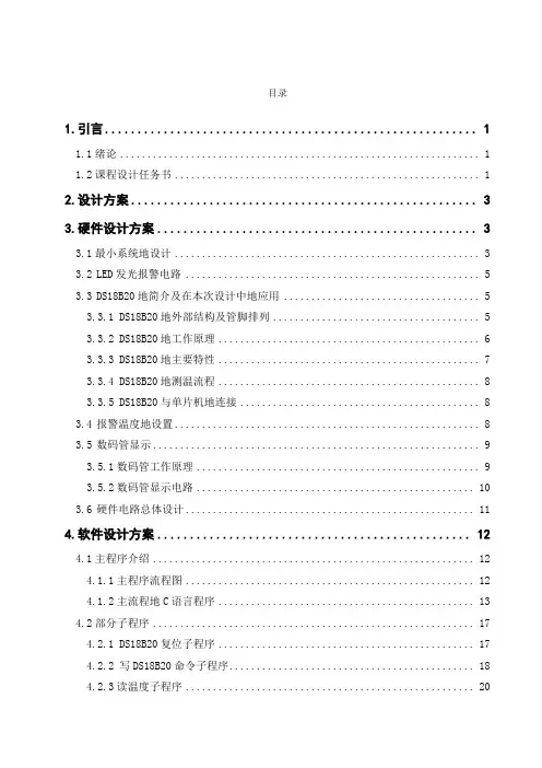
目录1.引言 (1)1.1绪论 (1)1.2课程设计任务书 (1)2.设计方案 (3)3.硬件设计方案 (3)3.1最小系统地设计 (3)3.2LED发光报警电路 (5)3.3DS18B20地简介及在本次设计中地应用 (5)3.3.1 DS18B20地外部结构及管脚排列 (5)3.3.2 DS18B20地工作原理 (6)3.3.3 DS18B20地主要特性 (7)3.3.4 DS18B20地测温流程 (8)3.3.5 DS18B20与单片机地连接 (8)3.4报警温度地设置 (8)3.5数码管显示 (9)3.5.1数码管工作原理 (9)3.5.2数码管显示电路 (10)3.6硬件电路总体设计 (11)4.软件设计方案 (12)4.1主程序介绍 (12)4.1.1主程序流程图 (12)4.1.2主流程地C语言程序 (13)4.2部分子程序 (17)4.2.1 DS18B20复位子程序 (17)4.2.2 写DS18B20命令子程序 (18)4.2.3读温度子程序 (20)4.2.4计算温度子程序 (22)4.2.5显示扫描过程子程序 (23)5.基于DS18B20地温度采集显示系统地调试 (25)6.收获和体会 (27)7.参考文献 (27)1.引言1.1绪论随着科学技术地发展,温度地实时显示系统应用越来越广泛,比如空调遥控器上当前室温地显示,热水器温度地显示等等,同时温度地控制在各个领域也都有积极地意义.采用单片机对温度进行控制不仅具有控制方便、简单、灵活性大等特点,而且还可以大幅度提高被控温度地技术指标.本文介绍了基于DS18B20地温度实时采集与显示系统地设计与实现.设计中选取单片机AT89C51作为系统控制中心,数字温度传感器DS18B20作为单片机外部信号源,实现温度地实时采集.并且用精度较好地数码管作为温度地实时显示模块.利用单片机程序来完成对DS18B20与AT89C51地控制,最终实现温度地实时采集与显示.采用单片机对温度进行控制不仅具有控制方便、简单、灵活性大等特点,而且还可以大幅度提高被控温度地技术指标.1.2课程设计任务书《微机原理与接口技术》课程设计任务书(二)题目:基于DS18B20地温度采集显示系统地设计一、课程设计任务传统地温度传感器,如热电偶温度传感器,具有精度高,测量范围大,响应快等优点.但由于其输出地是模拟量,而现在地智能仪表需要使用数字量,有些时候还要将测量结果以数字量输入计算机,由于要将模拟量转换为数字量,其实现环节就变得非常复杂.硬件上需要模拟开关、恒流源、D/A转换器,放大器等,结构庞大,安装困难,造价昂贵.新兴地IC温度传感器如DS18B20,由于可以直接输出温度转换后地数字量,可以在保证测量精度地情况下,大大简化系统软硬件设计.这种传感器地测温范围有一定限制(大多在-50℃~120℃),多适用于环境温度地测量.DS18B20可以在一根数据线上挂接多个传感器,只需要三根线就可以实现远距离多点温度测量.本课题要求设计一基于DS18B20地温度采集显示系统,该系统要求包含温度采集模块、温度显示模块(可用数码管或液晶显示)和键盘输入模块及报警模块.所设计地系统可以从键盘输入设定温度值,当所采集地温度高于设定温度时,进行报警,同时能实时显示温度值.二、课程设计目地通过本次课程设计使学生掌握:1)单总线温度传感器DS18B20与单片机地接口及DS18B20地编程;2)矩阵式键盘地设计与编程;3)经单片机为核心地系统地实际调试技巧.从而提高学生对微机实时控制系统地设计和调试能力.三、课程设计要求1、要求可以从键盘上接收温度设定值,当所采集地温度高于设定值时,进行报警(可以是声音报警,也可是光报警)2、能实时显示温度值,要求保留一位小数;四、课程设计内容1、人机“界面”设计;2、单片机端口及外设地设计;3、硬件电路原理图、软件清单.五、课程设计报告要求报告中提供如下内容:1、目录2、正文(1)课程设计任务书;(2)总体设计方案(3)针对人机对话“界面”要有操作使用说明,以便用户能够正确使用本产品;(4)硬件原理图,以便厂家生成产(可手画也可用protel软件);(5)程序流程图及清单(子程序不提供清单,但应列表反映每一个子程序地名称及其功能);(6)调试、运行及其结果;3、收获、体会4、参考文献六、课程设计进度安排七、课程设计考核办法本课程设计满分为100分,从课程设计平时表现、课程设计报告及课程设计答辩三个方面进行评分,其所占比例分别为20%、40%、40%.2.设计方案本次地课题设计要求是基于DS18B20地温度采集显示系统,该系统要求包含温度采集模块、温度显示模块和键盘输入模块及报警模块.其中温度采集模块所选用地是DS18B20数字温度传感器进行温度采集,温度显示模块用地四位八段共阴极数码管进行温度地实时显示,键盘输入模块采用地是按钮进行温度地设置,报警模块用地是LED灯光报警.具体方案见图2-1.图2-1 总体设计方案3.硬件设计方案3.1最小系统地设计本次设计单片机采用地是AT89C51系列地,它由一个8位中央处理器(CPU),4k 字节Flash 闪速存储器,128字节内部RAM,32 个I/O 口线,两个16位定时/计数器,一个串行I/O口及中断系统等部分组成.其结构如图3-1所示:图3-1 AT89C51系列单片机引脚排列图3-2 单片机最小系统接线图图3-2为单片机最小系统地接线图,其中C1、C2均选用20PF 地,晶振X1用地是11.0592MHZXTAL1XTAL2 RST EA地.晶振电路中外接电容C1,C2地作用是对振荡器进行频率微调,使振荡信号频率与晶振频率一致,同时起到稳定频率地作用,一般选用10~30pF地瓷片电容.并且电容离晶振越近越好,晶振离单片机越近越好.晶振地取值范围一般为0~24MHz,常用地晶振频率有6MHz、12 MHz、11.0592 MHz、24 MHz 等.晶振地振荡频率直接影响单片机地处理速度,频率越大处理速度越快.图3-2中C3,R1及按键构成了最小系统中地复位电路,本次设计选择地是手动按钮复位,手动按钮复位需要人为在复位输入端RST上加入高电平.一般采用地办法是在RST端和正电源Vcc之间接一个按钮.当人为按下按钮时,则Vcc地+5V电平就会直接加到RST端.由于人地动作再快也会使按钮保持接通达数十毫秒,所以,完全能够满足复位地时间要求.在单片机最小系统中还要将EA地非接高电平,如图3-2也有体现出来.3.2 LED发光报警电路P1.7图3-3 LED发光报警电路图3-3为LED报警电路地接法,其中一根线接单片机地8号P1.7口,另外一根接地.当温度超过预设温度值时LED灯被接通发光报警.3.3 DS18B20地简介及在本次设计中地应用3.3.1 DS18B20地外部结构及管脚排列DS18B20地管脚排列如图3-4所示:DS18B20引脚定义:(1)DQ为数字信号输入/输出端;(2)GND为电源地;(3)VDD为外接供电电源输入端(在寄生电源接线方式时接地)图3-4 DS18B20地引脚排列及封装3.3.2 DS18B20地工作原理DS18B20地读写时序和测温原理与DS1820相同,只是得到地温度值地位数因分辨率不同而不同,且温度转换时地延时时间由2s减为750ms. DS18B20测温原理如图3-5所示.图中低温度系数晶振地振荡频率受温度影响很小,用于产生固定频率地脉冲信号送给计数器1.高温度系数晶振随温度变化其振荡率明显改变,所产生地信号作为计数器2地脉冲输入.计数器1和温度寄存器被预置在-55℃所对应地一个基数值.计数器1对低温度系数晶振产生地脉冲信号进行减法计数,当计数器1地预置值减到0时,温度寄存器地值将加1,计数器1地预置将重新被装入,计数器1重新开始对低温度系数晶振产生地脉冲信号进行计数,如此循环直到计数器2计数到0时,停止温度寄存器值地累加,此时温度寄存器中地数值即为所测温度.图中地斜率累加器用于补偿和修正测温过程中地非线性,其输出用于修正计数器1地预置值.图3-5 DS18B20测温原理图3.3.3 DS18B20地主要特性(1)适应电压范围更宽,电压范围:3.0~5.5V,在寄生电源方式下可由数据线供电;(2)独特地单线接口方式,DS18B20在与微处理器连接时仅需要一条口线即可实现微处理器与DS18B20地双向通讯;(3)DS18B20支持多点组网功能,多个DS18B20可以并联在唯一地三线上,实现组网多点测温;(4)DS18B20在使用中不需要任何外围元件,全部传感元件及转换电路集成在形如一只三极管地集成电路内;(5)温范围-55℃~+125℃,在-10~+85℃时精度为±0.5℃;(6)可编程地分辨率为9~12位,对应地可分辨温度分别为0.5℃、0.25℃、0.125℃和0.0625℃,可实现高精度测温;(7)在9位分辨率时最多在93.75ms内把温度转换为数字,12位分辨率时最多在750ms内把温度值转换为数字,速度更快;(8)测量结果直接输出数字温度信号,以"一线总线"串行传送给CPU,同时可传送CRC校验码,具有极强地抗干扰纠错能力;(9)负压特性:电源极性接反时,芯片不会因发热而烧毁,但不能正常工作.3.3.4 DS18B20地测温流程图3-6 DS18B20地测温流程图3.3.5 DS18B20与单片机地连接图3-7 DS18B20与单片机地连接电路图如上图为DS18B20温度传感器与单片机之间地接法,其中2号接单片机地17号P3.7接口.DS18B20通过P3.7口将采集到地温度实时送入单片机中.3.4 报警温度地设置P2.5 P2.6 P2.7P3.7图3-8 报警温度地设置电路图3-8为报警温度地设置电路,其中K1,K2,K3分别接到单片机地P2.5,P2.6,P2.7口.其中K1用于报警温度设定开关,K2用于报警温度地设置时候地加温度(每次加一),K3用于报警温度地设置时地减温度(每次减一).实现了报警温度地手动设置.3.5 数码管显示3.5.1数码管工作原理图3-9 数码管地引脚排列及结构图3-9为数码管地外形及引脚排列和两种接法(共阴极和共阳极)地结构图.共阳极数码管地8个发光二极管地阳极(二极管正端)连接在一起.通常,公共阳极接高电平(一般接电源),其它管脚接段驱动电路输出端.当某段驱动电路地输出端为低电平时,则该端所连接地字段导通并点亮.根据发光字段地不同组合可显示出各种数字或字符.此时,要求段驱动电路能吸收额定地段导通电流,还需根据外接电源及额定段导通电流来确定相应地限流电阻.共阴极数码管地8个发光二极管地阴极(二极管负端)连接在一起.通常,公共阴极接低电平(一般接地),其它管脚接段驱动电路输出端.当某段驱动电路地输出端为高电平时,则该端所连接地字段导通并点亮,根据发光字段地不同组合可显示出各种数字或字符.此时,要求段驱动电路能提供额定地段导通电流,还需根据外接电源及额定段导通电流来确定相应地限流电阻.要使数码管显示出相应地数字或字符,必须使段数据口输出相应地字形编码.字型码各位定义为:数据线D0与a字段对应,D1与b字段对应……,依此类推.如使用共阳极数码管,数据为0表示对应字段亮,数据为1表示对应字段暗;如使用共阴极数码管,数据为0表示对应字段暗,数据为1表示对应字段亮.如要显示“0”,共阳极数码管地字型编码应为:11000000B(即C0H);共阴极数码管地字型编码应为:00111111B(即3FH).依此类推,可求得数码管字形编码如表3-5所示.表3-5数码管字符表显示地具体实施是通过编程将需要显示地字型码存放在程序存储器地固定区域中,构成显示字型码表.当要显示某字符时,通过查表指令获取该字符所对应地字型码.3.5.2数码管显示电路图3-10 四位八段数码管动态显示电路图3-10为本次设计所用到地四位八段数码管动态显示,其中段选接到单片机地P0口,位选接到单片机地P2口地低四位.其中P0口也接地有上拉电阻,图中未标示出来,会在下面地总体电路中标示出来.采用地是动态显示方式.3.6 硬件电路总体设计图3-11为本次设计地硬件总体设计图,其中利用K1,K2,K3处进行报警温度地设置,然后有DS18B20进行实时温度采集,并在数码管上同步显示,若采集到地温度达到或者超过预设地报警温度,则LED 灯会发光报警,若低于该报警温度,则不会报警.P0.1 P0.2 P0.3 P0.4 P0.5 P0.6 P0.7 P2.0 P2.1P2.2 P2.3图3-11 硬件电路总体设计图4.软件设计方案4.1主程序介绍4.1.1主程序流程图本次设计首先对程序进行初始化,然后打开报警温度设定开关,对报警温度进行设定,确认设定值后,DS18B20温度传感器进行温度采集并送入单片机中,单片机将传感器所检测到地温度同步显示在数码管上,并且与设置地报警温度进行比较,若达到或者超过报警温度时,LED灯发光报警,如果没有达到,则继续进行温度采集.图4-1主程序流程图4.1.2主流程地C语言程序main (){ALERT=0。
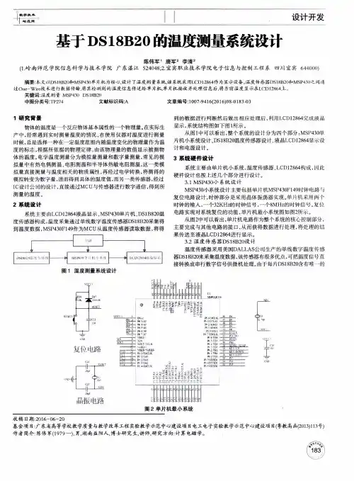
基于单总线数字温度传感器DS18B20的测温系统设计摘要:设计了一种基于单总线数字温度传感器DS18B20 的测温系统,给出了DS18B20 传感器特性和控制命令及时序,在Proteus 环境下进行了测温系统硬件设计,同时采用。
Keil 软件完成了系统主程序、DS18B20 驱动程序的设计;最后进行了系统Proteus 仿真,提高了系统开发效率,并获得了良好的仿真实验结果。
关键词:温度传感器;DS18B20;控制命令;驱动程序;Proteus 仿真0 引言温度是基本物理量之一,是工农业生产和日常生活中经常需要测试的重要参数,温度测量亦是应用频率最高的技术之一,在粮食仓库存储、环境监测、过程温度监测、中央空调监测、医学体温检测等领域有着广泛应用。
传统的温度检测方式一般采用热电偶或热敏电阻,输出模拟信号,经A/D 转换后才能送入单片机处理器,检测电路复杂。
因此,本文采用单总线智能型数字温度传感器DS18B20,以AT89C51 单片机为核心处理器,进行测温系统设计,在Proteus 环境中进行系统硬件设计,并结合软件进行了仿真,降低了开发成本,提高了开发效率。
1 DS18B20 传感器特性与控制时序DS18B20 是美国DALLAS 半导体公司的单总线智能型数字温度传感器,它通过单总线与处理器进行数据传输,主要由64 位ROM、温度敏感元件、非易失性温度告警触发器TH 和TL、配置寄存器组成。
供电范围为3.0~5.5 V;测温范围为- 55~125℃,可根据系统需求通过设置配置寄存器中的R1,R0 位调整为9~12 位分辨率,对应的可分辨温度和最大转换时间如表1 所示;每个DS18B20 器件有惟一的序列号,多个DS18B20 器件可接至同一个单总线上构成多点分布式温度测量系统;具有极强的抗干扰纠错能力。
DS18B20 的TO-92 封装如图1 所示,针脚1 为电源地线,针脚2 为数据输。
DS18B20构成的多点温度测量系统的设计multi-point temperature measurement system design withDS18B20关键字:DS18B20温度测量,多点温度测量系统设计四川大学蒋鸿宇王勇植涌引言在传统的温度测量系统设计中,往往采用模拟技术进行设计,这样就不可避免地遇到诸如引线误差补偿、多点测量中的切换误差和信号调理电路的误差等问题;而其中某一环节处理不当,就可能造成整个系统性能的下降。
随着现代科学技术的飞速发展,特别是大规模集成电路设计技术的发展,微型化、集成化、数字化正成为传感器发展的一个重要方向「1」。
美国Dallas半导体公司推出的数字温度传感器DSl8820,具有独特的单总线接口,仅需要占用一个通用I/O端口即可完成与微处理器的通信;在-10~+85℃温度范围内具有±0.5℃精度;用户可编程设定9~12位的分辨率。
以上特性使得DSl8820非常适用于构建高精度、多点温度测量系统。
1 DSl8B20简介1.1 DSl8B20的特点DSl8820是美国Dallas半导体公司继DSl820之后最新推出的一种改进型智能数字温度传感器[2]。
与传统的热敏电阻相比,它能够直接读出被测温度,并且可根据实际要求通过编程实现9~12位的数字值读数方式;可以分别在93.75 ms和750 ms内完成9位和12位的数字量;从DSl8820读出信息或写入DSl8820信息仅需要1根口线(单线接口);温度变换功率来源于数据总线,总线身也可以向所挂接的DSl8820供电,而无需额外电源。
使用DSl8820可使系统结构更趋简单,可靠性更高。
DSl8B20在测温精度、转换时间、传输距离、分辨率等方面较DSl820有了很大的改进。
1.2 DSl8B20内部结构及工作原理DSl8B20的内部结构「3」如图1所示,主要包括寄生电源电路、64位只读存储器(ROM)和单线接口、存储器和控制逻辑、存放中间数据的高速暂存存储器、温度传感器、报警上限寄存器TH、报警下限寄存器TL、配置寄存器和8位CRC(循环冗余校验码)发生器。
本科生毕业设计(论文)外文翻译译文题目:DS18B20 单线温度传感器外文题目:DS18B20 Single - wire temperature sensor学院:信息科学与工程学院专业班级:电子信息工程0804班学生姓名:指导教师:DS18B20 Single - wire temperature sensor一. FEATURES● Unique 1-Wireinterface requires only one port pin for communication● Each device has a unique 64-bit serial code stored in an onboard ROM● Multidrop capability simplifies distributed temperature sensing applications● Requires no external components● Can be powered from data line. Power supply range is 3.0V to 5.5V● Measures temperatures from –55°C to +125°C (–67°F to +257°F) 0.5 C accuracy from–10°C to +85°C● Thermometer resolution is user-selectable from 9 to 12 bits● Converts temperature to 12-bit digital word in 750ms (max.)● User-definable nonvolatile (NV) alarm settings● Alarm search command identifies and addresses devices whose temperature isoutside of programmed limits (temperature alarm condition)● Available in 8-pin SO (150mil), 8-pin SOP, and 3-pin TO-92 packages● Software compatible with the DS1822● Applications include thermostatic controls, industrial systems, consumerproducts, thermometers, or any thermally sensitive二. DESCRIPTIONThe DS18B20 Digital Thermometer provides 9 to 12–bit centigrade temperature measurements and has an alarm function with nonvolatile user-programmable upper and lower trigger points. The DS18B20 communicates over a 1-Wire bus that by definition requires only one data line (and ground) for communication with a central microprocessor. It has an operating temperature range of –55°C to +125°Cand is accurate to 0.5 C over the range of –10°C to +85°C. In addition, the DS18B20 can derive powerdirectly from the data lin e (“parasite power”), eliminating the need for an external power supply.Each DS18B20 has a unique 64-bit serial code, which allows multiple DS18B20s to function on the same 1–wire bus; thus, it is simple to use one microprocessor to control many DS18B20s distributed over a large area. Applications that can benefit from this feature include HV AC environmental controls, temperature monitoring systems inside buildings, equipment or machinery, and process monitoring and control systems.三. OVERVIEWFigure 1 shows a block diagram of the DS18B20, and pin descriptions are given in Table 1. The 64-bit ROM stores the device’s unique serial code. The scratchpad memory contains the 2-byte temperature register that stores the digital output from the temperature sensor. In addition, the scratchpad provides access to the 1-byte upper and lower alarm trigger registers (TH and TL), and the 1-byte configuration register. The configuration register allows the user to set the resolution of the temperature-to-digital conversion to 9, 10, 11, or 12 bits. The TH, TL and configuration registers are nonvolatile (EEPROM), so they will retain data when the device is powered down.The DS18B20 uses Dallas’ exclusive 1-Wire bus protocol that implements bus communication using one control signal. The control line requires a weak pullup resistor since all devices are linked to the bus via a 3-state or open-drain port (the DQ pin in the case of the DS18B20). In this bus system, the microprocessor (the master device) identifies and addresses devices on the bus using each device’s unique 64-bit code. Because each device has a unique code, the number of devices that can be addressed on one bus is virtually unlimited. The 1-Wire bus protocol, including detailed explanati ons of the commands and “time slots,” is covered in the 1-WIRE BUS SYSTEM section of this datasheet。
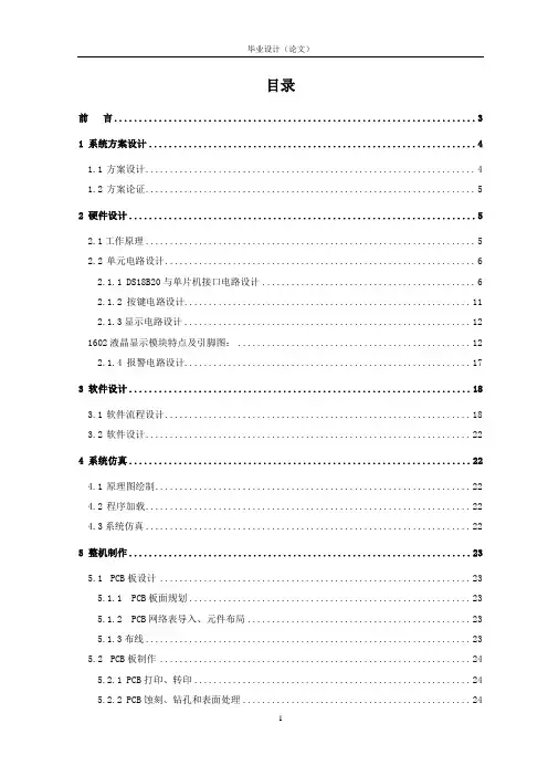
目录前言 (3)1 系统方案设计 (4)1.1方案设计 (4)1.2方案论证 (5)2 硬件设计 (5)2.1工作原理 (5)2.2单元电路设计 (6)2.1.1 DS18B20与单片机接口电路设计 (6)2.1.2 按键电路设计 (11)2.1.3显示电路设计 (12)1602液晶显示模块特点及引脚图: (12)2.1.4 报警电路设计 (17)3 软件设计 (18)3.1软件流程设计 (18)3.2软件设计 (22)4 系统仿真 (22)4.1原理图绘制 (22)4.2程序加载 (22)4.3系统仿真 (22)5 整机制作 (23)5.1PCB板设计 (23)5.1.1 PCB板面规划 (23)5.1.2 PCB网络表导入、元件布局 (23)5.1.3布线 (23)5.2PCB板制作 (24)5.2.1 PCB打印、转印 (24)5.2.2 PCB蚀刻、钻孔和表面处理 (24)5.3整机制作与调试 (25)5.3.1 元器件焊接 (25)5.3.2 整机调试 (26)总结 (26)参考资料 (26)致谢 (27)附录1 部分子程序 (28)前言21世纪,科学技术的发展日新月异,科技的进步带动了测量技术的发展,现代控制设备的性能和结构发生了翻天覆地的变化。
我们已经进入了高速发展的信息时代,测量技术也成为当今科技的一个主流,广泛地深入到研究和应用工程的各个领域。
温度是一个和人们生活环境有着密切关系的物理量,也是一种在生产、科研、生活中需要测量和控制的重要物理量,是国际单位制七个基本量之一。
温度的变化会给我们的生活、工作、生产等带来重大影响,因此对温度的测量至关重要。
其测量控制一般使用各式各样形态的温度传感器。
随着现代计算机和自动化技术的发展,作为各种信息的感知、采集、转换、传输相处理的功能器件,温度传感器的作用日显突出,已成为自动检测、自动控制系统和计量测试中不可缺少的重要技术工具,其应用已遍及工农业生产和日常生活的各个领域。
石家庄铁道大学四方学院基于DS18B20的蔬菜大棚多点测温系统设计The Design ofVegetable Greenhouse Multi-point Temperature Measurement System Based onDS18B20完成日期 20XX年5月15日成绩单摘要温度是影响蔬菜大棚内作物生长的重要因素,温度过高或过低,都会影响蔬菜的生长。
传统的温度控制是用温度计来测量,并根据此温度人工来调节其温度。
但仅靠人工控制既耗人力,又容易发生差错。
为此,现代的蔬菜大棚管理中通常需要温度自动检测控制系统,对蔬菜大棚内的温度进行实时检测控制,以使蔬菜大棚内的作物保持在最佳的生长状态。
本文介绍了基于AT89C51单片机和10个DS18B20传感器的蔬菜大棚多点测温系统。
其中DS18B20为温度采集模块, AT89C51单片机作为主要控制器,并配合数码管显示电路,按键控制电路,温度上下限调整电路,声光报警等电路实现10点单总线多点温度的检测、显示、温度上下限可调的温度检测系统。
通过按键对单片机的工作状态进行控制,确定其工作在测温状态、报警状态、还是设定状态。
按键设定温度上下限,以适应不同种类、不同生长时期作物生长所需最适温度的要求。
在系统设计过程中充分考虑性价比,选用价格低、微功耗、性能稳定的元器件。
该温度测量仪具有连接点数多,传输距离远,扩展方便,便于构成采集系统及价格低廉等优点,非常适用于多点蔬菜大棚的温度检测,能够方便准确地显示蔬菜大棚内的温度,且省时省力。
能有效保证蔬菜的正常生长,为蔬菜的生长提供稳定的环境场所。
关键词:温度DS18B20 单总线多点蔬菜大棚AbstractTemperature is an important factor to affect crop growth in the vegetable greenhouse. The temperature will affect the growth of vegetables when it is too high or too low. Traditional temperature control with a thermometer to measure the manual is to adjust the temperature according to this temperature. However, merely relying on the manual control not only waste the labor force but also prone to error. To this end, modern vegetable greenhouse management usually requires automatic temperature control system is detected. The real-time detection and control of temperature in the vegetable greenhouse will keep the vegetable greenhouse crops maintaining an optimal growth state.This paper introduces the vegetable greenhouses multi-point temperature measurement system based on AT89C51 microcontroller, C language, and 10 DS18B20 sensor. DS18B20 is the temperature acquisition module. AT89C51microcontroller as the main controller with the display circuit and digital key control circuit, the lower limit on the temperature adjustment circuit, sound and light alarm circuit is the system. The temperature detection system can realize the 10 points temperature detection, display and adjustment by a single bus.The keys control the working status of the microcontroller to determine its work in the temperature status, alarm status, or set the state. The buttons is to set the temperature lower limit to acmodate the types of different growth stages of crop growth and the optimum temperature required. Fully considering the cost-effective in the system design process I selected low price, micro-power consumption and stable performance ponents. The temperature gauge has a number of connection points, the transmission distance; the expansion is convenient, easy to form a collection system and the advantages of low prices. The system is ideal for multi-point temperature of the vegetable greenhouses detection. It can easily and accurately shows the temperature inside the vegetable greenhouses. What’s more, It effectively guarantee the normal growth of vegetables and provide a stable environment for the growth of vegetables places.Key words:Temperature DS18B20Multi-point by a single bus Vegetable greenhouse目录4.3DS18B20时序及有关程序 (20)致谢第1章绪论1.1研究的背景及意义近年来,随着我国农业科技的发展,蔬菜大棚技术得到了广泛的普及应用,温室大棚数量日渐增多。
目录1、前言 (2)2、温度控制系统设计 (3)2.1方案选择 (3)2.2整体电路设计 (3)3、电路模块设计 (4)3.1电源电路模块 (4)3.2 STC89C52控制芯片 (4)3.3 DS18B20温度控制芯片 (7)3.3.1 DS18B20简介 (7)3.3.2 DS18B20的性能特点 (7)3.3.3 DS18B20供电方式 (8)3.3.4 DS18B20测温原理 (8)3.4复位电路模块 (9)3.5显示电路模块 (10)3.5.1移位寄存器74HC164 (10)3.5.2数码管显示电路 (11)3.6报警电路模块 (12)3.7按键电路模块 (12)4、软件设计 (13)4.1控制流程图 (13)4.2 DS18B20工作过程及时序 (13)4.2.1初始化时序 (13)4.2.2写时序 (14)4.2.3读时序 (15)5、闭环控制 (17)5.1 被控对象的传递函数测定 (17)5.2控制算法 (17)6、系统调试 (20)7、结论 (21)参考文献 (23)附录 (24)1、前言温度控制系统广泛应用于社会生活的各个领域,如家电、汽车、材料、电力电子等,常用的控制电路根据应用场合和所要求的性能指标有所不同, 在工业企业中,如何提高温度控制对象的运行性能一直以来都是控制人员和现场技术人员努力解决的问题。
这类控制对象惯性大,滞后现象严重,存在很多不确定的因素,难以建立精确的数学模型,从而导致控制系统性能不佳,甚至出现控制不稳定、失控现象。
传统的继电器调温电路简单实用,但由于继电器动作频繁,可能会因触点不良而影响正常工作。
控制领域还大量采用传统的PID控制方式,但PID控制对象的模型难以建立,并且当扰动因素不明确时,参数调整不便仍是普遍存在的问题。
而采用数字温度传感器DS18B20,因其内部集成了A/D 转换器,使得电路结构更加简单,而且减少了温度测量转换时的精度损失,使得测量温度更加精确。
外文资料翻译资料来源:第七届国际测试技术研讨会文章名:The Principle of the Intelligent Temperature Sensor DS18B20and Its Application作者:LI Shuo LI Xiaomi文章译名:智能温度传感器DS18B20的原理与测量姓名:学号:指导教师(职称):专业:班级:所在学院:译文智能温度传感器DS18B20的原理及其应用摘要:功能和结构的数字本文介绍了温度测量芯片DS18B20的温度测量系统的介绍,8051单片机作为其作品CPU和DALLAS18B20其温度数据收集 - 转换。
硬件的原理,软件程图和一个短暂的时间延迟子程序也都给予列出。
关键词:DS18B20温度传感器,单片机微机,硬件设计一、导言单轨数字温度传感器DS18B20的生产由美国DALLAS公司。
它可以转换的温度信号成字信号提供的微电脑处理直接。
与传统的相比热敏电阻器,它可以直接读出的措施温度并根据实际它可以actualize 9〜12的数值读数方式通过简单的编程。
信息读取或写入DS18B20的,只需要一个单一的线。
温度变换功率来源于为主线,主线本身可以供电源DS18B20的,不需要额外的电源。
因此,如果使用DS18B20的,系统的结构会更简单,更可靠。
因为每个DS18B20包含一个独特的硅序列号,多个DS18B20s 可以存在于相同的1-Wire总线。
这允许浇筑温度传感器在许多不同的地方。
应用场合此功能是有用的,包括HVAC环境控制,检测建筑物内的温度,设备或机械,过程监测和控制。
二、 DS18B20的结构DS18B20的四个组成部分的主要数据:(1)64位光刻ROM(2)温度传感器(3)非易失性温度报警触发器TH和TL(4)配置寄存器。
设备源于其权力从1-Wire通信线通过储能在一段时间的内部电容当信号线为高,并继续操作此期间的低倍的电源关闭1-Wire线,直到它返回来补充高寄生虫(电容器)供应。
基于DS18B20温度传感器的温度测量系统设计张仲明;郭东伟;吕巍;张立明【摘要】设计了一种基于 DS18B20温度传感器的温度测量系统,该系统由DS18B20温度传感器、STC89C516RD+单片机与LCM 液晶显示屏组成.构建了实验电路图并实现了仿真实验.结果显示本系统的测量结果与温度计的实际测量结果基本吻合,符合预期仿真结果.%Based on the DS18B20 temperature sensor,a temperature measurement system is designed.This system is composed of the DS18B20 temperature sensor,STC89C516RD+ SCM and LCM LCD screen.The experimental circuit diagram is set up and the simulation experiment is realized.The results show that the measurement results of this system are basically in agreement with the actual measurement results of the thermometer,which conforms to the expected simulation ones.【期刊名称】《实验技术与管理》【年(卷),期】2018(035)005【总页数】5页(P76-79,88)【关键词】温度测量系统;DS18B20温度传感器;STC89C516RD+单片机【作者】张仲明;郭东伟;吕巍;张立明【作者单位】吉林大学计算机科学与技术学院,吉林长春 130012;吉林大学物联网虚拟仿真实验教学中心,吉林长春 130012;吉林大学计算机科学与技术学院,吉林长春 130012;吉林大学物联网虚拟仿真实验教学中心,吉林长春 130012;吉林大学计算机科学与技术学院,吉林长春 130012;吉林大学物联网虚拟仿真实验教学中心,吉林长春 130012;吉林大学计算机科学与技术学院,吉林长春 130012;吉林大学物联网虚拟仿真实验教学中心,吉林长春 130012【正文语种】中文【中图分类】TH811温度测量与控制是工业自动控制的重要组成部分,在工业、电子、精度实验等领域有着普遍的应用[1]。
毕业设计外文资料翻译外文出处:2007 Second IEEE Conference on Industrial Electronics and Applications学院:信息工程系:电子信息工程专业:电子信息工程班级:学号:学生姓名:外文原文:A Design of the Temperature Test System Basedon Grouping DS18B20LI Ping ZHOU Yucai Xiangjun ZENG YANG Ting-fangChangsha University of Science and Technology,Changsha 410077, Hunan, P. R. China.E-Mail:0702liping@Abstract- All the DS18B20 sensors, used for the multipoint test temperature, are connected with MCU on one of IO bus, and temperature data are collected by turns. If the system has a large amount of sensors, the time of MCU used in processing the temperature data is obviously prolonged, so the cycle of alternate test gets longer. In this paper, a new method that DS18B20 are rationally grouped is presented, and some measures are taken in software; as a result, the speed of alternate test advances distinctly.Key words- DS18B20 Group ,temperature test, time spent on the alternate test.I. INTRODUCTIONAs the simple structure, convenient installment, low loss and wide range of temperature test, DS18B20 temperature test sensors are applied to the fields which need the multipoint temperature test, such as the chemical industry, the grain, the environment supervision and so on. Because of the adoption of one bus in theDS18B20 multipoint temperature test system, all DS18B20 are hung on one bus, and then the temperature conversion value of each test point is read by turns. As the conversion value must be read after reading-pin state for 8 times, and position and store data must be moved, so time spend much in reading one point of the data system by every time. If the temperature test system is large-scaled, the system loss caused by it is rather much, and then the alternate test speed of the system decreases obviously, which influences the efficiency of the multipoint temperature test system seriously. In this paper, DS18B20 are hung on some I/O buses by grouping DS18B20 evenly, and the conversion temperature data is obtained by reading the state of DS18B20, then the system loss decreases and the alternate test speed increases obviously, which won’t influence the precision and the reliability of the conversion. A set of multipoint temperature test of artificial environment laboratory is achieved in this paper, which increases the test efficiency of the former system.Ⅱ. CHARACTERISTICS OF DS18B20DS18B20 is the single bus digital temperature sensor from American Dallas Company. DS18B20 is consisted of the 64 figures ROM engraved by laser, the temperature sensitivity component, non-volatile temperature alarms trigger (Device TH and TL).DS18B20 communicates with the microprocessor by the single bus portand the test range of DS18B20 is from -55 centigrade to +125 centigrade, and the incremental value is 0.5 centigrade. The temperature can be changed into figures within 720ms and each DS18B20 has the sole 64 figures serial number. The specific content is revealed as Fig 1: There are two 8 figures storages (No.0 and No.1) for storing temperature value in DS18B20. No.0 storage stores complement of the temperature value, and No.1 stores symbols of the temperature value. The user can define non-volatile temperature alarms sets and distinguish the alarms search order and seek the component temperature alarms state outside the scheduled limit. There are two alternative ways of power supply: Signal bus high-level borrow power is adopted, or the +5v power supply externally is adopted directly.Fig 1 DS18B20 64bit ROMⅢ. APPLICATION THE GROUPING TEST METHOD This paper illustrates the grouping method with the interface of DS18B20 and 89C52. Assuming the amount of the buses on P1 port is 4 and the temperature test system needs 100 DS18B20 sensors, which can be distributed equally to the 4 I/O lines. If the number of sensors cannot be divided by the number of buses even, the number disparity of sensorson buses is no more than one, which can be handled while reading numbers. The power is supplied externally. Owning to the synchronistic conversion in each DS18B20, the intense current is needed, and the signal bus cannot be used for the power supply, otherwise the system cannot work in order. The schematic circuit is shown as Fig 2 (the DS18B20 signal buses of the same group are hung on some buses of P1 port). When read and write the DS18B20, the strict schedule must be kept. First a reversion pulse is sent to all DS18B20. After the reversion, Skip ROM order is sent to each circuitsimultaneously from the I/O port, and the conversion order is sent, then all sensors begin transform. After the conversion, Match Rom order is sent to each circuit simultaneously, and 64 bits serial number is sent. DS18B20 is selected for each group, and Scratch Pad data is read. Finally the data is transformed. The data of serial-read is transformed into the actual temperature value. One alternate test is finished after the DS18B20 temperature data is read completely by the cyclical reading for 25 times. The whole flow chart is shown as Fig 3.Fig 3 the diagram of collecting temperature by grouped DS18B20Now the time-consuming in the test system of the singlebus and the grouping analyses method is illustratedrespectively. The reversion time sequence and the time sequence of writing and reading one bit for themicroprocessor are revealed in figures 4-6. The figure show:The reversion period of DS18B20 is 495us-1020us;thewriting period of one bit is 60us-120us;the reading period ofone bit is above 60us; the span of writing or reading the nextbit is 1us. As the A/D conversion time is 97.35ms (9precisions), if it is counted by the shortest way, the totaltime-consuming of alternate test is calculated respectively asfollows:(1) Single bus495us+2*(8*60+7)us+97.35ms+495us+100*(64*60+63+8*60+7+9*60+8)us=552.53 4ms(2) Grouping mode495us+2*(8*60+7)us+97.35ms+20(64*60+63+8*60+7+9*60+8)us=189.804msAs the small proportion of the numeration systemconversion and the storage time in the whole period, theunknown crystal-oscillator frequency, the numeration system conversion and storage time is not counted. Accordingly, thealternate test time which grouping mode consumes is muchshorter than single bus mode obviouslyFig 4 DS18B20 reversion time sequenceFig 4 DS18B20 reversion time sequenceIV. EXAMPLE OF THE DESIGNThe asphalt transportation vehicle is the maintransportation equipment between the material field and roadsurface. The unavoidable temperature decreasing because ofthe asphalt transportation vehicle’s long working andtransportation distance influences the paving quality of theroad surface, the specific measures must be taken accordingto the heat release of the shell. This paper designed a set ofwireless temperature using DS18B20 grouping mode testsystem for testing the temperature of the asphalttransportation vehicle shell, and the total points is 120.Temperature test system software adopts the modular design.The hypogenous machine collects data, stores data, sets upDS18B20, and sends the wireless module and so on. Theepigenous machine adopts PC machines, mainly receives thetemperature data from the hypogenous machine. Theepigenous machine displays, stores and manages data. Thesimple communication between people and machines isperformed by the epigenous machine. This paper will notillustrate the simple procedure of the epigenous machine indetail. The following is the illustration of parts of hypogenous machine. including the components of system hardware ,software functions and process.A. System hardwareConsidering the multipoint temperature number of thetemporary storage and the considerable internal RAM duringthe value conversion, the chief controlling chip adoptsATMEL 89C52 Single-Chip Microcomputer with 256 bytesRAM and 8KBE2PROM procedure storage. As thedistinguishable code of DS18S20 is read and numbered, theliquid crystal module (Ao Kela Chinese integrated module ofOCMJ Jin Peng Company) and the keyboard module areadded. The wireless digital transmission adopts the wireless module PTR2000 in the whole reception-sending form, which may has two amateur bands to choose and the regulative BaudRate ( the max is 20Kbit/s), and the Single-ChipMicrocomputer serial port data can be received directly. Thesystem hardware structure is shown as Fig 7:DS18B20, with the power supply, divided into 8 groupshung on P1 port(P1.0-P1.7). The wireless module is hung onserial port directly and the hardware watchdog adopts theMAX813 chip. When the power is added to the system, the89C52 reversion signal is transmitted from the MAX813reversion pin, and the value of the reversion pulse is 200ms.When the procedure is in order, a pulse signal must be sent toMAX813 WDI pin in no more than the interval of 1.6s toclear away thewatch-dog timer. If the interval is more than1.6s, the pin does not receive the pulse signal, and then the89C52 must be reversed. As 120 DS18B20 serial numbersmust be stored in the system, the data storage DS1225 (8K)against the power failure is developed.B. System software function and processThe software part of the temperature test system numbersDS18B20, collects and transforms data, performs the wirelesscommunication, manages keyboard and so on. For theconvenience of the procedure debugging and the reliability,the module design is adopted, mainly including the keyboardprocessing module, the wireless communication module, themodule of temperature collection and processing, the displaymodule and so on. The software flow chart is shown as Fig 8 After the reversion of add power 89C52 self-checks first, then allocates each branch procedure module. The chiefprocedure manages the keyboard, initializes the system and transfers each functional module. The haul line is kept toperform DS18B20 edit mission. 120 points serial number ofDS18B20 is read by the keyboard and display coordinationand numbered into DS1225Y. First the wireless module is set up as the reception state to receive the collection parameters and start the order (The transmission content is sent by pack ; the same content is sent for three times ; two out of three logic is performed according to the bit).The wireless module is set up as the sleep state during theconversion and the transforming state during the temperaturedata transmission. Packing sends the temperature data and theDS18B20 numbers in the system to epigenous machine. The parts of collection and conversion start the DS18B20conversion, read the temperature data by grouping methods,store data and so on. The following procedure is the main content of collecting and conversion modules:void Get_ Temperature(void){ uchar i,j , temp_ lsb, temp_ msb;for(i=0;i<8;i++){skip_rom(i);//skip over the serial numbers to checkwrite_bytes(0x44 );}//transform the temperature in each circuit at the same timefor(j=0;j<100;j++)// prolong the time for 0.1s; wait for the end of conversion{delay(1000);}For(j=0;j<15;j++){ match_ rom(j); read_ scratchpads (j); }//each temperature value is read in 8 busesfor(j=0;j<120;j++){temp_lsb = temp_pad[j][0] ;//the data conversion of the temperature valuetemp_msb = temp_pad[j][1] ;temp_lsb >>= 4 ; temp_msb <<= 4 ;temp_lsb |=temp_msb; temp_msb = (temp_lsb/10) ;temp_msb <<=4 ; temp_lsb %= 10 ;temp_lsb |=temp_msb; temperature_ vel[j] =temp_lsb;}}V. CONCLUSIONAuthors create the following new ideas1)Alternate test time difference of the multipointtemperature test system in the grouping method and the singlebus method is analyzed, then the alternate test speed can beincreased greatly by grouping method.2)A set of wireless multipoint temperature test system isdesigned by DS18B20 grouping method. This system isapplied to the technology reform of the asphalt transportationvehicle in some domestic large-scale engineering mechanicalcompany and the good result of the application is achieved.REFERENCES[1] ShenJin,SongJingLing. An All-digital Temperature Measuring SystemUsed in Grain Barns.Transaction of the chese society for Agricultural Machinery,2001,(2):89 91.[2] LiMinHui, Jung Deqiong. A Device of Temperature MeasuremenMade upofDS1820 and AT89C205. Journal of Sichan NormalUniversity1997,(5):93-96 [3] Qi ZhiCai Gai Shuang. Embedded Control System of the CentralAir conditioner Room,InstrumentTechnique and Sensor2002,(5):25-26.[4] ZhangPeiren ZhouYanping. A Large-Scale Temperature AlarmSystem Based on 1 Wire Bus and CAN bus, Control&Automation2003,(2):25-26译文:基于DS18B20分组方式温度测试系统设计摘要:当用于多点测温时,所有的DS18B20传感器都连接在单片机的某根总线上,采用轮流采集温度数据的方式。