A Simple Model of the Magnetoresistance Contribution to the Magnetoimpedance Effect in Thin
- 格式:pdf
- 大小:139.79 KB
- 文档页数:2

高三英语人工智能单选题40题1. Artificial intelligence is a branch of computer science that aims to create intelligent _____.A.machinesB.devicesC.equipmentsD.instruments答案解析:A。
“machines”通常指机器,在人工智能领域常指具有一定智能的机器;“devices”一般指设备、装置;“equipments”是“equipment”的复数形式,指装备、器材;“instruments”指仪器、工具。
2. In the field of artificial intelligence, algorithms are used to train _____.A.modelsB.patternsC.shapesD.forms答案解析:A。
“models”在人工智能中常指模型,可以通过算法进行训练;“patterns”指模式、图案;“shapes”指形状;“forms”指形式。
3. Deep learning is a powerful technique in artificial intelligence that uses neural _____.worksB.systemsC.structuresanizations答案解析:A。
“networks”指网络,在深度学习中常指神经网络;“systems”指系统;“structures”指结构;“organizations”指组织。
4. Artificial intelligence can process large amounts of data to make accurate _____.A.predictionsB.forecastsC.projectionsD.expectations答案解析:A。
浙江省温州市2019年中考英语试卷10小题,每小题1分,共10分)1.— Peter, shall we go for a picnic this Sunday?— OK. Let's add it to _____________ weekend plan.A.a B.an C.the D./2.— Sir, did you enjoy your stay in our________________?— Yes, I slept well and I like the breakfast.A.hotel B.school C.factory D.company3.The living room becomes ____________as the sunlight comes in through the windows.A.bigger B.cleaner C.quieter D.brighter4.Sam finds sweeping robots useful, and he plans to buy ___________ for his grandma.A.it B.one C.this D.that5.Betty felt so tired last night that she ____________ fell asleep in bed after lying down.A.recently B.suddenly C.frequently D.immediately 6.We don't allow taking magazines out, but you ____________ copy the article you need on the machine over there.A.can B.must C.should D.would7.The instructions tell us everything ____________ about how to make the model ship.A.by hand B.by chance C.in detail D.in person 8.—Linda, Dad has finished his work and we ___________ to the gym to pick you up.—Thank you, Mum.A.drive B.drove C.have driven D.are driving9.— Could you tell me ____________________?— You will stay with an English family and take part in their daily life.A.when I should pay for the courseB.what the best part of the course isC.how long the shortest course lastsD.where I can go sightseeing after class10.—Tony, hurry up and don't forget to lock the door.— ___________________. I'm getting my coat.A.Wait a minute B.No dealC.Nothing serious D.Bad luck15小题,每小题1分,共15分)11.阅读短文,掌握大意,然后从每小题所给的A、B、C、D四个选项中选出最佳选项。
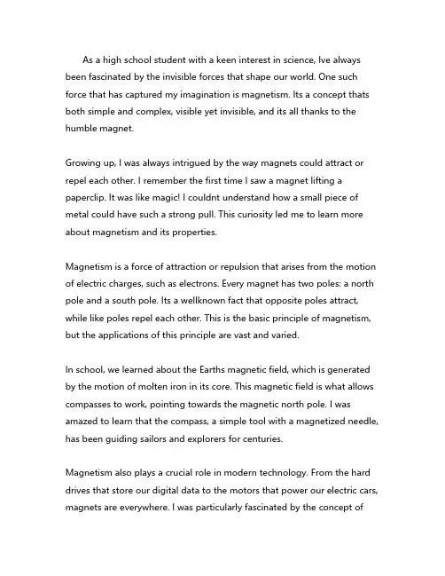
As a high school student with a keen interest in science, Ive always been fascinated by the invisible forces that shape our world. One such force that has captured my imagination is magnetism. Its a concept thats both simple and complex, visible yet invisible, and its all thanks to the humble magnet.Growing up, I was always intrigued by the way magnets could attract or repel each other. I remember the first time I saw a magnet lifting a paperclip. It was like magic! I couldnt understand how a small piece of metal could have such a strong pull. This curiosity led me to learn more about magnetism and its properties.Magnetism is a force of attraction or repulsion that arises from the motion of electric charges, such as electrons. Every magnet has two poles: a north pole and a south pole. Its a wellknown fact that opposite poles attract, while like poles repel each other. This is the basic principle of magnetism, but the applications of this principle are vast and varied.In school, we learned about the Earths magnetic field, which is generated by the motion of molten iron in its core. This magnetic field is what allows compasses to work, pointing towards the magnetic north pole. I was amazed to learn that the compass, a simple tool with a magnetized needle, has been guiding sailors and explorers for centuries.Magnetism also plays a crucial role in modern technology. From the hard drives that store our digital data to the motors that power our electric cars, magnets are everywhere. I was particularly fascinated by the concept ofelectromagnetic induction, which is the principle behind generators and electric motors. Its incredible to think that the simple interaction of a magnet and a coil of wire can generate electricity.One of my favorite experiments in school was creating a homemade electromagnet. All it took was a coil of wire, a battery, and an iron nail. When I connected the wire to the battery, the iron nail became a magnet, capable of attracting other metal objects. It was a simple demonstration of electromagnetism, but it was also a testament to the power of magnetism.Magnetism is not just limited to the physical world. It has also inspired many metaphors and analogies. For example, we often talk about people being magnetic personalities, drawing others towards them with their charm and charisma. Similarly, we describe strong attractions as magnetic.Despite its ubiquity, magnetism still holds many mysteries. Scientists are still researching the properties of superconducting magnets and their potential applications in medicine and energy storage. The quest for understanding the nature of magnetism is an ongoing journey of discovery.In conclusion, magnetism is a fundamental force that has shaped our world in countless ways. From the Earths magnetic field to the technology that powers our lives, the influence of magnetism is everywhere. As a high school student, I am excited to continue exploring the wonders of magnetism and the many ways it shapes our world.。
小学上册英语第4单元期中试卷英语试题一、综合题(本题有100小题,每小题1分,共100分.每小题不选、错误,均不给分)1.The sun is ______ (bright) during the day.2.He is ___ his bicycle. (riding)3.The energy needed to start a chemical reaction is called _______ energy.4.What is the sum of 3 and 4?A. 5B. 6C. 7D. 8答案:D5.My favorite holiday is ________ (情人节) with friends.6.The __________ (古代文化) has influenced modern art and literature.7.The process of filtration separates solids from ______.8.I have a ________ that shares my secrets.9.The _____ (小鸟) builds a nest in the tree. It lays eggs there. 小鸟在树上筑了一个巢。
它在里面下蛋。
10.What do you call a group of stars?A. GalaxyB. PlanetC. CometD. Asteroid答案:A11.________ (生物多样性保护) is essential for ecosystems.12.The ________ (analysis) informs decisions.13.在1754年到1763年之间,美国发生了________ (French and Indian War)。
14.The vulture is a _______ (食腐动物).15.The ______ is the part of a plant that attracts pollinators.16.My dad loves to watch __________. (体育)17.Many plants have adapted to survive in nutrient-poor ______. (许多植物已适应在养分贫乏的土壤中生存。
2024-2025学年北师大版英语小学六年级上学期自测试题及解答参考一、听力部分(本大题有12小题,每小题2分,共24分)1、Listen to the conversation and choose the correct answer.Conversation:Boy: Hi, Jane. What’s your favorite subject?Girl: Well, I really like science because we get to do fun experiments.Question: What is Jane’s favorite subject?A. MathB. ScienceC. ArtAnswer: B. Science.Explanation: In the dialogue, Jane explicitly states that she likes science because of the fun experiments they get to do in class.2、Listen to the short passage and choose the correct answer.Passage:Today in our school trip, we went to the zoo. We saw many different animals, but my favorite part was seeing the dolphins perform tricks. They jumped through hoops and danced with their trainers. It was amazing!Question: What was the narrator’s favorite part of the school trip?A. Seeing the elephantsB. Watching the dolphin showC. Feeding the birdsAnswer: B. Watching the dolphin show.Explanation: The passage clearly mentions that the narrator’s favorite part was seeing the dolphins perform tricks at the zoo during the school trip.3、Listen to the conversation and answer the question.W: Hello, John. How was your science fair project?M: Oh, it was amazing! I built a model of a solar-powered car.W: That sounds impressive. What did you learn from it?M: Well, I learned a lot about renewable energy and how it can help reduce pollution.Question: What did John build for his science fair project?A) A model of a wind turbineB) A model of a solar-powered carC) A model of a traditional carD) A model of a hydroelectric power plantAnswer: B) A model of a solar-powered car解析:在对话中,John提到他制作了一个太阳能汽车的模型,因此正确答案是B。
小学上册英语第六单元测验卷(有答案)英语试题一、综合题(本题有100小题,每小题1分,共100分.每小题不选、错误,均不给分)1.I want to grow a ________ that brings happiness.2. A ______ (草本植物) is often used for culinary purposes.3.The __________ (历史遗产) can be tangible or intangible.4.What is the name of the technology that allows us to communicate over distances?A. TelevisionB. RadioC. TelephoneD. Computer答案: C5.The ______ (植物的适应能力) is key to survival.6.My dad is a __________ (投资顾问).7.Which animal is known as "man's best friend"?A. CatB. DogC. BirdD. Fish答案:B.Dog8.I enjoy ________ (跳舞) at parties.9. A ______ (果园) is where fruit trees are grown.10.__________ energy is required to break chemical bonds.11.The ______ loves to play music.12.The __________ is known for its ancient monuments.13.The __________ is a famous desert in the United States.14.What is a common pet that purrs?A. DogB. CatC. BirdD. Fish答案: B15.The __________ is a major city known for its art and culture. (巴黎)16.My ________ (老师) encourages us to do our best in school.17.y of __________ (凡尔赛) ended World War I in 1919. The Troj18.The baby is _____ (crying/laughing) loudly.19.The __________ is a region known for its heat and dryness.20.I find ________ (古典文学) very inspiring.21.The boy likes to play ________.22.The chemical formula for cobalt chloride is _____.23.The __________ is famous for its unique rock formations.24.The ________ (squirrel) is looking for nuts.25.My toy ____ can turn into a car. (玩具名称)26.I enjoy painting my ________ (玩具类型).27.Every Saturday, I go to the _______ (地方) with my family. We enjoy _______ (活动) together.28.I enjoy _______ (drawing) in my sketchbook.29.What do we call the leader of a country?A. PresidentB. MayorC. GovernorD. Senator答案: A30. A ____ is a playful animal that loves to chase after balls.31.My grandma enjoys visiting ____ (libraries).32.Chemistry is the study of ______ and their interactions.33. A __________ is a smaller body of water connected to a larger body.34.Which planet is known as the Blue Planet?A. MarsB. EarthC. VenusD. Jupiter答案: B35.What is the color of an emerald?A. RedB. BlueC. GreenD. Yellow答案: C36.My ________ (玩具名称) can turn into different characters.37.The butterfly has colorful ______ (翅膀). It flutters from flower to ______ (花).38.I can ________ (calculate) numbers easily.39.The _____ (pollen) helps plants reproduce.40.我的朋友喜欢 _______ (活动). 她觉得这很 _______ (形容词)41.I like to _______ (study) science.42.We are making ________ (果汁) for breakfast.43.What do we call the process of changing from a caterpillar to a butterfly?A. TransformationB. EvolutionC. GrowthD. Metamorphosis答案: D44.We need to _______ (遵守) the law.45.I enjoy riding my ______ (滑板) at the skate park. It is a lot of ______ (乐趣).46.The element with the atomic number is ______.47.The capital of Portugal is ________ (里斯本).48.The classroom is ________ (安静的).49.What do you call the process of a solid becoming a liquid?A. FreezingB. MeltingC. EvaporatingD. Condensing答案: B50.The first successful airplane flight took place in ________.51.My friend is very __________ (灵活).52.What is the capital of Russia?A. MoscowB. St. PetersburgC. KievD. Minsk答案:A53.The chemical formula for potassium carbonate is ______.54. A horse gallops quickly across the _______.55.The ____ enjoys basking in the sun on warm days.56.The chemical symbol for uranium is _____.57.The _______ point is the temperature at which a liquid turns to a gas.58.My grandma enjoys making __________ (传统食品).59.The country known for its wildlife is ________ (以野生动物闻名的国家是________).60.My cat loves to chase ______ (蝴蝶) in the garden.61.The __________ (克里米亚战争) involved many European powers.62.The _____ (秋天) leaves are falling.63.The ______ is a measure of how much matter is in an object.64.I love to collect ______ (邮票) from different countries. They are very ______ (特别).65.The chemical formula for sodium thiosulfate is ______.66.The _______ (小蜻蜓) flits around over the water.67.What do you call the main character in a story?A. VillainB. ProtagonistC. NarratorD. Supporting character答案:B68. A ______ (猴子) swings from branch to branch in trees.69.He is reading a ________ (书) in the library.70.The main gas emitted from car exhaust is _______.71.The chemical formula for calcium carbonate is __________.72.The first man to walk on the moon was ______ (尼尔·阿姆斯特朗).73.I think it's essential to be respectful to __________.74.We enjoy ______ (fishing) at the lake.75.What is the name of the fairy in Peter Pan?A. Tinker BellB. CinderellaC. Snow WhiteD. Ariel答案: A76.I have a toy _______ that can build things.77.I can ______ (write) my name in cursive.78.We are _____ (waiting) for the bus.79.The ______ is known for her artistic skills.80.I enjoy drawing ______ animals.81.The movie starts at _______ (七点).82.An atom is the smallest unit of a ______.83.The ________ is a beautiful creature that glows.84.The plant needs more ___ (water).85.The ancient Greeks celebrated ________ as a tribute to their deities.86.The _______ can thrive in various climates.87.My ________ (玩具) is perfect for outdoor play.88.The Earth revolves around the ______.89. A __________ is an area where two tectonic plates meet.90.What is the main ingredient in pancakes?A. RiceB. FlourC. CornD. Oats答案: B91.ground Railroad helped slaves escape to ________ (自由). The Unit92.The crust is made up of both continental and ______ landforms.93.The _____ (自然景观) features a variety of plant habitats.94.The antelope's agility keeps it safe from predators, ensuring its ____.95.The butterfly has colorful ______.96.My sister calls me her _______ because we are close.97. A _______ can be used to measure the flow rate of a liquid through a pipe.98.The __________ in the summer can be really hot. (天气)99.I like to ___ (play/read) stories.100.I need to _____ (finish/start) my homework.。

专利名称:Reference cell configuration for sensingresistance states of MRAM bit cells发明人:Yue-Der Chih,Chun-Jung Lin,Kai-ChunLin,Hung-Chang Yu申请号:US13438006申请日:20120403公开号:US08687412B2公开日:20140401专利内容由知识产权出版社提供专利附图:摘要:A reference circuit discerns high or low resistance states of a magneto-resistive memory element such as a bit cell. The reference circuit has magnetic tunnel junction(MTJ) elements in complementary high and low resistance states Rand R, providing a voltage, current or other parameter for comparison against the memory element to discern a resistance state. The parameter represents an intermediate resistance straddled by Rand R, such as an average or twice-parallel resistance. The reference MTJ elements are biased from the same read current source as the memory element but their magnetic layers are in opposite order, physically or by order along bias current paths. The reference MTJ elements are biased to preclude any read disturb risk. The memory bit cell is coupled to the same bias polarity source along a comparable path, being safe from read disturb risk in one of its two possible logic states.申请人:Yue-Der Chih,Chun-Jung Lin,Kai-Chun Lin,Hung-Chang Yu地址:Hsin-Chu TW,HsinChu TW,Hsin-Chu TW,Hsin-Chu TW国籍:TW,TW,TW,TW代理机构:Duane Morris LLP更多信息请下载全文后查看。
高二英语科学概念高级应用单选题45题1.The force acting on an object is directly proportional to its acceleration. If the force on an object is doubled, its acceleration will _____.A.be halvedB.remain the sameC.be doubledD.be quadrupled答案:C。
解析:根据牛顿第二定律F=ma,力与加速度成正比。
当力加倍时,加速度也会加倍。
A 选项加速度减半错误;B 选项加速度不变错误;D 选项加速度变为四倍错误。
2.In an electromagnetic field, the direction of the magnetic field is perpendicular to the direction of the electric field. If the electric field points north, the magnetic field cannot point _____.A.eastB.southC.westD.north答案:D。
解析:因为磁场方向与电场方向垂直,所以当电场指向北时,磁场不能指向北。
A 选项东与北垂直,有可能;B 选项南与北垂直,有可能;C 选项西与北垂直,有可能。
3.When an object is in equilibrium, the sum of all forces acting on it is _____.A.zeroB.greater than zeroC.less than zeroD.indeterminate答案:A。
解析:物体处于平衡状态时,所受合力为零。
B 选项大于零错误,物体将有加速度;C 选项小于零错误,同理;D 选项不确定错误。
4.The work done on an object is equal to the force applied multiplied by the distance moved in the direction of the force. If a force of 10 N moves an object 5 meters in its direction, the work done is _____.A.2 JB.50 JC.15 JD.25 J答案:B。
小学上册英语第四单元真题(含答案)考试时间:80分钟(总分:120)B卷一、综合题(共计100题共100分)1. 选择题:Which animal is known for its ability to change colors?A. ChameleonB. FrogC. ParrotD. Snake2. 选择题:What is the primary language spoken in the USA?A. SpanishB. FrenchC. EnglishD. German答案:C. English3. 填空题:The __________ (历史的融合) creates understanding.4. 填空题:The _____ (小鹿) hides in the bushes.5. 填空题:The goldfish swims gracefully in the _________ (水).6. 选择题:What is the capital of Japan?A. BeijingB. SeoulC. TokyoD. Bangkok7. 听力题:A force can change the motion of an ______.8. 听力题:The Doppler effect can be observed in light from _______.9. 填空题:The _____ (小羊) bleats softly when calling for its mother.10. 听力题:We eat lunch at ___. (noon)11. 听力题:Lunar and solar eclipses occur in ______.12. 选择题:What do we call the line that divides the Earth into the Northern and Southern Hemispheres?A. EquatorB. Prime MeridianC. Tropic of CancerD. Tropic of Capricorn13. 选择题:What is the capital of Lithuania?a. Vilniusb. Kaunasc. Klaipedad. Šiauliai答案:a14. 选择题:What do we call the person who studies rocks and minerals?A. GeologistB. ArchaeologistC. BiologistD. Chemist答案: A15. 听力题:The _____ is a type of galaxy that has a spiral shape.16. 填空题:The kangaroo's pouch is used to carry its ______ (幼崽).17. 选择题:What is the term for a young cat?A. KittenB. PupC. CubD. Calf答案:A. Kitten18. 填空题:My friend enjoys creating __________ (视频) on YouTube.19. 听力题:A _____ occurs when a comet passes close to the sun.20. 听力题:A __________ is a type of bird known for its colorful feathers.21. 听力题:The capital of Austria is __________.22. 听力题:My brother is a ______. He loves to build robots.23. 选择题:What is 20 10?A. 5B. 10C. 15D. 20答案:B24. 听力题:The chemical formula for calcium phosphate is ______.25. 选择题:What is the opposite of "happy"?A. SadB. AngryC. ExcitedD. Tired答案:A26. 填空题:The ________ (新发现) change our understanding of geography.27. 填空题:My favorite superhero ________ (玩具名称) flies in the sky.28. 听力题:A ____ has big ears and can hear very well.29. current) affects navigation and marine life. 填空题:The ____30. 填空题:My aunt's birthday is in ____.31. 选择题:What is the name of the first successful landing on the far side of the moon?A. Apollo 11B. Chang'e 4C. Luna 16D. Surveyor 132. 填空题:My ___ (仓鼠) runs fast on its wheel.33. 选择题:What do we call the frozen form of water?A. SteamB. LiquidC. IceD. Snow答案:C34. 听力题:The __________ is a region known for its rich biodiversity.35. 听力题:A _______ can grow from a cutting in water.36. 填空题:The __________ (花香) fills the air in spring.37. 填空题:The kangaroo can jump very _______ (高).38. 填空题:The ancient Egyptians built their pyramids as tombs for their ______ (法老).39. 选择题:What is the capital city of Kosovo?A. PristinaB. GjakovaC. MitrovicaD. FerizajWhat is the name of the famous detective created by Arthur Conan Doyle?A. Hercule PoirotB. Sherlock HolmesC. Miss MarpleD. Philip Marlowe答案:B41. 听力题:In chemistry, a solution is a _______ mixture.42. 填空题:The _____ (植物) needs water to survive.43. 听力题:The chemical symbol for samarium is ______.44. 听力题:A saturated solution contains the maximum amount of _____.45. 填空题:The _______ (鲸鱼) is a giant sea animal.46. 选择题:What is the name of the famous American holiday celebrated on the last Monday of May?A. Memorial DayB. Labor DayC. ThanksgivingD. Independence Day答案:A47. 填空题:The __________ (古代文明) had their own writing systems.48. 选择题:What is the main ingredient in salad?A. RiceB. LettuceC. PastaD. Bread答案:B49. 填空题:My grandma is a wonderful __________ (顾问)._____ (雨水收集) supports sustainable gardening.51. 填空题:The ______ (小鱼) swims with its friends.52. 听力题:We need to ___ (study) for the test.53. 填空题:My cousin is my cheerful _______ who plays with me.54. 听力题:The symbol for zirconium is _____.55. 选择题:What do we call the process of changing from a liquid to a solid?A. FreezingB. MeltingC. EvaporationD. Condensation答案: A56. 选择题:Which fruit is yellow and curved?A. OrangeB. BananaC. PearD. Apple57. 填空题:The ________ is very interesting.58. 填空题:My hamster loves to explore its ______ (笼子).59. 填空题:The parrot can learn to _______ (说话) easily.60. 听力题:The simplest form of a carbohydrate is a ______.61. 填空题:The __________ (历史的声音) resonates with truth.They are friends from ________ (学校).63. 选择题:What is the smallest continent?A. AfricaB. AsiaC. AustraliaD. Europe答案:C64. 填空题:I love to watch ________ (舞蹈表演) on TV.65. 听力题:The element with atomic number is __________.66. 听力题:The chemical formula for iron(III) oxide is _______.67. 听力题:A chemical reaction can involve the transformation of _____.68. 听力题:We have _____ (two/four) eyes.69. 填空题:My best friend is very __________ (诚实的).70. 填空题:A __________ (气味) can indicate the presence of certain chemicals.71. ohs ruled ancient ________ (埃及). 填空题:The Pilg72. 填空题:We have a ______ (丰富的) library at school.73. 听力题:Coral reefs are made up of tiny ______ creatures.74. 听力题:A chemical reaction that releases heat is called an ________ reaction.75. 选择题:What do we call a place where you can see many animals?A. ZooB. FarmC. AquariumD. Nature reserve76. 填空题:The __________ is a major city located along the coast. (旧金山)77. 填空题:A __________ (化学安全) is crucial in laboratory settings to prevent accidents.78. 选择题:What is 15 7?A. 6B. 7C. 8D. 9答案:C. 879. 听力题:The bear finds honey in a _____ tree.80. 听力题:She is _____ (singing) a song.81. 听力题:A chemical that can donate electrons is called a ______.82. 填空题:The ________ was a noteworthy leader in the grassroots activism movement.83. 选择题:What is the capital of India?A. MumbaiB. DelhiC. KolkataD. Chennai答案:B84. 选择题:What do we call a person who studies weather patterns?A. GeologistB. MeteorologistC. BiologistD. Climatologist答案: B. MeteorologistThe _______ of air pressure affects the weather.86. 选择题:How many players are there in a soccer team?A. 9B. 10C. 11D. 12答案:C87. 听力题:A _____ is a phenomenon where the moon blocks the sun.88. 填空题:A ________ (植物保护组织) advocates for conservation.89. 填空题:We have a big _____ (玩具车) collection.90. 听力题:There are many cars on the ___. (road)91. 听力题:A __________ is a tool used by geologists to analyze rock samples.92. 填空题:This girl, ______ (这个女孩), is a great athlete.93. 填空题:I like to ______ (参与) in environmental projects.94. 听力题:A solution that does not conduct electricity is called a ______ solution.95. 填空题:The __________ (博物馆) has many interesting exhibits.96. 选择题:What is the chemical symbol for potassium?A. PoB. KC. PtD. P答案: BThe process of making lemonade is an example of creating a _____.98. 填空题:I love to ______ (探索) new ideas.99. 听力题:The pencil is ___ (sharp/dull).100. (13) Pole is covered in ice. 填空题:The ____。
大学英语六级(阅读)模拟试卷7(题后含答案及解析)题型有: 2. Reading Comprehension (Skimming and Scanning) 4. Reading Comprehension (Reading in Depth)Part II Reading Comprehension (Skimming and Scanning) (15 minutes)Directions: In this part, you will have 15 minutes to go over the passage quickly and answer the questions attached to the passage. For questions 1-4, mark:Y (for YES) if the statement agrees with the information given in the passage;N (for NO) if the statement contradicts the information given in the passage;NG (for NOT GIVEN)if the information is not given in the passage.The New Machine —Move Over Data! The potential of integrated applications in medical technology and patient monitoring is as exciting as it is exotic. Remember the Star Trek robot who could speak 5,000 languages and who was familiar with the protocols(礼仪)of many worlds? Not only can Data talk, reason and feel. It is almost impossible to shut him up! Well, the scientists at the Massachusetts Institute of Technology’s(MIT)Artificial Intelligence(AI)lab are exploring and creating robots that may someday rival Data’s accomplishments. The implications of their work —ranging from artificial limbs that feel, respond and act like the originals, to thinking machines —are moving fairly quickly from the realms of fantasy into those of probability. One robot, nicknamed Kismet, has even been programmed to read human facial expressions and react “emotionally”. Kismet has a disembodied head, albeit a remarkably cute one with long eyelashes shading large blue eyes. Just as babies learn from reading and imitating the expressions and sounds made by their parents(with parents often projecting their emotions to the child), Kismet “learns” and reacts to the faces of its creators. While Kismet’s ability to interact and learn is primitive when compared to a human baby, it nonetheless elicits a great deal of “projected”humanity from those around it, and triggers some of the same emotions as an infant would from the adults that surround him or her. Children learn to be real people because the adults close to them are “programmed”(i. e., infants trigger hormonal and neuronal stimuli in adults)to treat them as real people. Thus, the scientists at MIT are predicting that humanoid robots may be possible if we treat them as if they were human! This work is fascinating in all of its facets —especially mat which teaches us about ourselves. “Do unto others as you would have them do unto you. “ And can you create who they are and how they treat you? “As you sow, so shall you reap!” While humans are infinitely more complex, making their reactions infinitely less predictable, even at the most primitive level, the impact of respectful and gentle interactions can be not clearly seen. Real News —Interactive Robot The real news, however, is Cog: an interactive robot that makes eye contact, plays catch, and bobbles a Slinky back and forth in its hands. Unlike robots in which a single central computer controls multiple separate mechanical systems, Cog is built with “embodied”intelligence —every joint has an independent “thinking”machine designed to interact in simple ways with the joints around it, and to take cues directly from its environment. This means, of course, that not even its creators know precisely how Cog will behave in every situation. And now the creators are working on Cog’s skin. Here’s what’s going on: to help build Cog’s arm coordination, the scientists put touch sensors in the robot’s belly(to give Cog’s hand something at which to aim). Cog was then programmed to touch the sensors, but its response was so life-like(as each affected joint responded)that it looked as if the robot was exploring its body —almost exactly like a human baby. Before that, Cog was a fascinating toy, but with “skin” it became a primitive human, although a mechanical one. Expanding Capabilities As robots like Cog become more,and more complex, their capabilities will expand rapidly into the work-a-day world, and certainly not as “pincers”awkwardly controlled by human hands, but rather as independently functioning units controlled by their own programming. Although we have worked for years on computer models of how the human brain works, and even built a computer that can beat a chess master at his or her own game, we have so far built pretty worthless robots. Why? The answer may lie in Cog’s “embodied intelligence”. As long as scientists insisted that all intelligence was centrally located in a computer that received information and gave commands to the mechanical systems that enabled the robot to move, we failed. Each joint and system has an intelligence of its own —and reacts to stimuli on its own —in addition to whatever commands it receives from the central computer. It is possible, perhaps probable, that Cog is successful because its systems are, at a most primitive level, mimicking our systems. That intelligence and even memory is stored in our various body parts and systems as well as our minds. The fact that Cog “came alive” when it was given skin(implanted with sensors)gives added meaning to therapeutic touch. As an interesting aside, in the 14th Century, Rabbi Abraham ibn Ezra interpreted the words in Genesis 3: 21 “... and Yahweh made garments for the man and his wife and clothed them.” The Rabbi thinks this means that Yahweh quite literally encased them in skin(their own skin, not an animal’s)and through this skin came knowledge of the world. Thus all human knowledge is “embodied. “It would seem that MIT’s Artificial Intelligence researchers are just catching up with him! Present and Potential Application Today we have robots that assist with micro- and tele-surgery. We even have a home health robot that reminds people to take their medicine at the prescribed times, and dispenses the appropriate drug in. the prescribed dose. We have voice-activated computers that record, store, dispense and charge. We have monitor systems that watch, secure record and warn. We have computerized compliance systems that record and track and match and advise. What we need, like Cog, is a way of connecting and integrating them while each maintains its own intelligence and its own interactivity. The potential of integrated applications in smart buildings, in decision-support environments(clinical and managerial), in medical technology, and patient monitoring-diagnosis-intervention(in the OR, in the ER, in the home), is as exciting as it is exotic. Soon, very soon, far sooner than most humans will be ready for it, MIT’s scientists are going to marry Kismet and Cog —and then, Data —move over! To take this thesis a step further, MIT’s AI researchers could join forces withneurobiologists whose work enables brain waves to be picked up, magnified and used to communicate and/or perform any function that a computer can perform. Humans actually could create their own doppelgangers(面貌极相似的人). Moreover, we are more than likely to live to see it happen.1.Data is a robot who is______.A.created by the scientists from Massachusetts Institute of TechnologyB.an imaginary image in a science fiction worldC.capable of doing all kinds of workD.good at nursing patients正确答案:B解析:第一句说Data是科幻电影<星际旅行冲的一个会很多种语言的机器人,由此可看出它是一个“虚构的形象”,因此,[B]项正确。
小学上册英语第1单元期中试卷(有答案)英语试题一、综合题(本题有100小题,每小题1分,共100分.每小题不选、错误,均不给分)1.My favorite _____ is a friendly little puppy.2.All living things are made up of _____ (cells).3.What is 5 + 2?A. 6B. 7C. 8D. 9答案:B 74. A substance that changes color when pH changes is called an ______.5.The park is ________ from my house.6.The capital of Chile is __________.7.The main product of photosynthesis is _______.8.My dad is known for his __________ (智慧).9.I love to _____ (dance/sing) at school.10.I like to ______ movies with my family. (watch)11.The Earth's crust is ______ than the mantle.12.The manatee is often found in warm ______ (水域).13. War in the United States was fought over ________ (奴隶制). The Code14. A peacock shows off its beautiful ______ (羽毛).15.My aunt loves __________ (跳舞).16.The process of changing a liquid to a gas is called ______.17._____ (草本植物) are used in many recipes.18.The alligator's powerful jaws can crush bones and ________________ (肉).19.I have many __________ (玩具名) at home.20.The _____ is known for its beautiful rings.21.What do we call the chemical element with the symbol H?A. HydrogenB. HeliumC. LithiumD. Oxygen答案: A. Hydrogen22.What do you call a long journey by foot?A. WalkB. HikeC. RunD. Travel答案:B23.I enjoy helping my parents cook dinner on ______ (周末).24. A __________ is a substance used to test pH levels.25.听录音,标序号。
高考英语阅读理解细节题单选题30题1. According to the passage, the latest technology in artificial intelligence can _____.A. completely replace human workersB. solve all the problems in the worldC. improve productivity significantlyD. lead to unemployment on a large scale答案:C。
文中明确提到最新的人工智能技术能够显著提高生产力,A 选项“完全取代人类工人”过于绝对,文中未提及;B 选项“解决世界上所有问题”不符合实际;D 选项“导致大规模失业”文中没有相关表述。
2. The new material developed by scientists is mainly used for _____.A. building stronger housesB. making faster carsC. curing serious diseasesD. reducing environmental pollution答案:A。
文中指出这种新开发的材料主要用于建造更坚固的房屋,B 选项“制造更快的汽车”、C 选项“治疗严重疾病”和D 选项“减少环境污染”在文中均未提及。
3. Which of the following is NOT a feature of the new energy storage device?A. High capacityB. Long lifespanC. Quick chargingD. Low cost答案:D。
文中描述了新能源存储设备具有高容量、长寿命和快速充电的特点,未提到低成本,所以选D。
4. The recent research on space exploration shows that _____.A. humans will live on Mars in the near futureB. there is no life on other planetsC. it is easy to travel to other galaxiesD. new discoveries have been made about the moon答案:D。
中考英语科技创新的人才需求单选题40题1. In the field of artificial intelligence, ____ is used to analyze a large amount of data quickly.A. algorithmB. batteryC. buttonD. bridge答案解析:A。
本题考查词汇在人工智能领域中的含义。
“algorithm”(算法)在人工智能领域用于快速分析大量数据,这是科技创新人才需要了解的基本概念。
“battery”(电池)、“button”(按钮)、“bridge”(桥)与分析大量数据无关。
从语法角度看,这里需要一个名词作主语,四个选项都是名词,但只有A符合语境。
2. Big data can help companies ____ their customers' needs better.A. understandB. forgetC. ignoreD. lose答案解析:A。
本题考查动词在大数据语境下的用法。
“understand”(理解)符合大数据帮助公司更好地了解客户需求这一概念,这是科技创新中利用大数据的一个重要方面。
“forget”((忘记)、“ignore”((忽视)、“lose”((失去)都不符合语境。
语法上,“help sb. do sth.”是固定用法,这里需要一个动词原形,A选项正确。
3. Many smart phones are now equipped with AI assistants, which can ____ voice commands.A. receiveB. refuseC. rewriteD. reduce答案解析:A。
本题考查动词在智能手机人工智能助手语境下的含义。
“receive”(接收)语音指令是人工智能助手的一个常见功能,科技创新人才需要掌握这类表达。
“refuse”((拒绝)、“rewrite”((重写)、“reduce”((减少)不符合这个语境。
八年级物理电磁学英语阅读理解20题1. Who discovered electromagnetic induction?A. Michael FaradayB. Isaac NewtonC. Albert EinsteinD. Galileo Galilei答案:A解析:根据电磁学的历史知识,迈克尔·法拉第发现了电磁感应现象,从电磁学历史相关内容中可得到答案。
2. Which of the following is a common application of magnetic fields?A. RefrigeratorsB. FlashlightsC. FansD. Radios答案:A解析:冰箱利用磁场来实现制冷等功能,这是磁场常见的应用,在电磁学实际应用场景知识中能找到依据。
3. The flow of electric charge is called _.A. V oltageB. ResistanceC. CurrentD. Power答案:C解析:在电磁学基本概念里,电荷的流动被称为电流,这是基本定义。
4. Which scientist is known for his work on electromagnetism and developed the theory of relativity?A. Nikola TeslaB. Albert EinsteinC. James Clerk MaxwellD. Thomas Edison答案:B解析:爱因斯坦以相对论闻名,同时他在电磁学方面也有相关工作成果,从科学家的成就相关知识可知。
5. In an electric circuit, what does a resistor do?A. Increases the currentB. Decreases the currentC. Changes the direction of the currentD. Stops the current completely答案:B解析:在电路中,电阻器的作用是减小电流,这是电路元件的基本功能知识。
小学下册英语第5单元测验试卷(有答案)考试时间:100分钟(总分:140)B卷一、综合题(共计100题共100分)1. 填空题:The _____ (bay) tree is aromatic.2. 填空题:The _______ (小蜜蜂) buzzes as it gathers nectar.3. 填空题:We have a ______ (快乐的) gathering for special occasions.4. 选择题:What is the opposite of 'fast'?A. QuickB. SpeedyC. SlowD. Rapid答案:C5. 填空题:My ________ (玩具名称) brings joy to everyone.6. 听力题:The capital of Bhutan is __________.7. (Mona Lisa) was painted by Leonardo da Vinci. 填空题:The ____8. 听力题:A _______ is an area of land that has been formed by volcanic activity.9. 选择题:What do we call a young walrus?A. PupB. CalfC. KitD. Chick答案:B. Calf10. 填空题:The prairie dog lives in _________ (地下).11. ssance encouraged exploration of new ________ (思想). 填空题:The Rena12. 听力题:The atomic model developed by Dalton was based on the idea that atoms are _______.13. 填空题:My uncle loves to __________ (分享) his travel stories.14. 选择题:What is the official currency of the United Kingdom?A. DollarB. EuroC. PoundD. Franc答案:C. Pound15. 填空题:I want to learn how to ________ (做手工).16. 填空题:The __________ (历史的广度) encompasses diversity.17. 填空题:My favorite dish is ______ (咖喱).18. 填空题:My ________ (玩具) is perfect for outdoor play.19. 填空题:I love writing stories about ________ (外星人) and their adventures in outer ________ (太空).20. 填空题:We picked ________ from the tree.21. 填空题:A ____(community wellness initiative) addresses health disparities.中国的历史上,各个________ (dynasties) 有着不同的特点与成就。
phys.stat.sol.(a)171,R3(1999)Subject classification:75.70.Ak;75.70.Pa;S1.1;S1.2A Simple Model of the Magnetoresistance Contribution to the Magnetoimpedance Effect in Thin FilmsJ.M.Barandiara Ân (a),G.V.Kurlyandskaya 1)(a),M.Va Âzquez (b),J.Gutie Ârrez (a),D.Garcia (b),and J.L.Mun Äoz (a,b)(a)Dpto de Electricidad y Electro Ânica,Facultad de Ciencias,Universidad del PaõÂs Vasco/EHU,Apartado 644,48080Bilbao,Spain;e-mail:galina@we.lc.ehu.es(b)Instituto de Magnetismo Aplicado UCM-RENFE and Instituto de Ciencia de Materiales CSIC,P .O.Box 155,28230Las Rozas (Madrid),Spain;e-mail:vazquezv@fenix.ima.csic.es(Received November 16,1998;accepted December 4,1998)Giant magnetotransport phenomena,as giant magnetoresistance (GMR)[1,2]and giant magnetoim-pedance (GMI)[3,4],have brought much interest in the basic physical understanding and their appli-cations as magnetic recording heads and in magnetic sensor technology.The origin of these phenom-ena is rather different:GMR is connected with spin dependent electron scattering in magnetically non-uniform systems for dc or low-frequency current.The magnetoimpedance effect (MI)consists in the change of the total impedance Z =R (w ,H )+iX (w ,H )(real and imaginary components)of a magnetic conductor under dc applied magnetic field,when a high-frequency ac current flows through it.The change of total impedance of the magnetic conductor has been attributed up to now only to the classical skin effect [5,6].This seems to be correct for the kind of materials used in technical GMI applications,which usually show negligible magnetoresistance (MR).Nevertheless,the basic under-standing of the MR influence on the total impedance Z (w ,H )is a very important task.A simple model can be developed as follows:let us suppose a thin film with no magnetic do-main structure and a high frequency ac current I I 0e i 3t flowing parallel to the Z -axis in the plane of the film.The sample has the thickness 2a in the X -axis direction,the Y -axis is in the plane of the sample and perpendicular to the current.The transverse permeability m Y is uniform.The total impedance Z =R +iX can be written asZ R DC i 1a 2q coth i 1a 2q Y 1where i =(±±1)1/2,R DC is the dc resistance [7,8],q 2is the normalized frequency q 2 a 2smw G r DC À1and s is the conductivity,w is the circular frequency,r =s ±±1is the sample resistivity.For the low1Permanent address:Institute of Metal Physics,Ural Division,Russian Academy of Sciences,Kova-levskaya str.18,GSP-170,620219Ekaterinburg,Russia.Fig.1.Effect of a)perpendicular and b)parallel MR on the magnetoimpedance normalized to Z (0)in the low-frequency limit.The evolution of r DC (H )(line)has been taken arbitrarily and mH follows the same trend in accordance with experimental data [9].Z (m )(open symbols)is the magnetoimpedance in the ab-sence of MR.Z (m ,r )(full symbols)is the combined effect;here Z |Z |represents the impedancemodulusfrequency limit q 2<<1,we have:R %R DC 1 q 445G r 1 A r À2 Y where A a 4m 2Y w 245Y X %R DC q 23G r À1Y 2 Z j j %R DC 1 790 q 4 G r 1 B r À2 Y where B 7a 4m 2Y w 290X The condition of the low-frequency limit applies,for example,to Permalloy (Fe 19Ni 81)films show-ing anisotropic MR effect.If we suppose typical values of 2a %1m m,m Y %104m 0,s %107W ±±1m ±±1and a frequency range of about 20to 30MHz,then q 2%0.02,i.e we are in the low frequency limit.The choosen conditions are quite reasonable and compare well with the experimental results in Permalloy [9].We define the change of the electrical resistivity (D r /r )||=[r (H )±±r (H max)]Â100/r (H max )as a parallel MR and (D r /r )c [r (H )±±r (H max)]Â100/r (H max )as a tranverse MR when the current flows parallel or perpendicular,respectively,to the applied dc field,H max is the maximum field,which saturates the sample and is applied along the Z -axis or Y -axes,respectively.The simulated behaviour for D r (H )/r 2%,D m /m (H ) 100/1,and q (H 0)%0.5has been analyzed,starting from eq.(2).The calculations show that the magnetoresistance contribution to the total impedance plays an important role both in parallel and perpendicular geometries,for the low-frequency limit (Fig.1).In this limit the change of skin depth due to the change in m Y is small and the magnetoim-pedance is of the same order as the magnetoresistance.Moreover,the MR contribution is additive,and largely enhances (transverse case)or almost supresses (parallel case)the MI effect (Fig.1).In the high frequency limit q 2)1,eq.(1)for the total impedance can be written asZ j j %R DC q G r 1a 2X3 The simulated behaviour for the parameters D r (H )/r 2%and D m /m (H ) 10/1shows no appre-ciable magnetoresistance contribution to the total magnetoimpedance (Fig.2).In the high-fre-quency limit the MR contribution to MI is reduced to about half the low-frequency contribution and the MI effect is much larger (about 300%in this case).In conclusion,the first calculations of the magnetoresistance contribution to the total impedance show that MR can play an important role in the low frequency limit but can be neglected for the high frequency limit.Acknowledgements The research has been partially supported by The Basque Government under the project PI97/113and The Spanish CICYT project MAT95/0273.G.V .Kurlyandskaya would like to acknowledge a fellowship of the Basque Government.We thank V .O.Vaskovskiy and V .N.Lepalovskij for helpful discussion.References[1]N.F.Mott ,Proc.Roy.Soc.156,638(1936).[2]J.Kondo ,Progr.Teor.Phys.(Kyoto)27,772(1962).[3]R.S.Beach and Berkowitz ,J.Appl.Phys.76,6209(1994).[4]L.V.Panina,K.Mohri,K.Bushida ,and M.Noda ,J.Appl.Phys.76,6198(1994).[5]R.L.Sommer and C.L.Chien ,J.Appl.Phys.79,5139(1996).[6]G.V.Kurlyandskaya,J.M.GarcõÂa-Beneytez,M.Va Âzquez,J.P.Sinnecker,V.A.Lukshina ,and A.P.Po-tapov ,J.Appl.Phys.83,6581(1998).[7]ndau and E.M.Lifshitz ,Electrodynamics of Continuous Media,Pergamon Press,Oxford 1975.[8]D.-X.Chen and J.L.Mun Äoz ,IEEE Trans.Magn.,submitted.[9]G.V.Kurlyandskaya,J.M.Barandiara Ân,J.Gutie Ârrez,V.O.Vaskovskiy,V.N.Lepalovskij,M.Va Âz-quez ,and D.GarcõÂa ,Appl.Phys.Lett.,submitted.Fig.2.Effect of MR on the MI normalized to Z (0)in the high-frequency limit (see eq.(3)).Same symbols as in Fig.1.Only the perpendicular configuration is represented (here Z |Z |)。