Band structures in two-dimensional phononic crystals with periodic Jerusalem cross slot
- 格式:pdf
- 大小:2.18 MB
- 文档页数:6
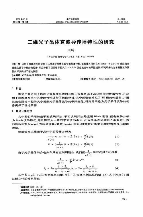
Fabrication of two-dimensional coupled photonic crystal resonator arrays by holographic lithographyG.Q.Liang,W.D.Mao,Y .Y .Pu,H.Zou,and H.Z.Wang a ͒State Key Laboratory of Optoelectronic Materials and Technologies,Zhongshan (Sun Yat-sen)University,Guangzhou 510275,People’s Republic of ChinaZ.H.ZengInstitute of Macromolecule,Zhongshan (Sun Yat-sen)University,Guangzhou 510275,People’s Republic of China͑Received 18April 2006;accepted 27May 2006;published online 24July 2006͒We demonstrate the holographic design and fabrication of two-dimensional coupled photonic crystal resonator arrays,which are composed of hexagonal cavities tiled together in a triangular lattice.Band structure analysis reveals that the inverse structure of the fabricated template supports monopole defect mode in a photonic band gap of TM polarization.Our results show the practical importance of holographic lithography in the fabrication of photonic component arrays.©2006American Institute of Physics .͓DOI:10.1063/1.2234743͔Holographic lithography 1has become a very important microfabrication method for photonic crystals,2,3in which a photoresist is used to record the interference patterns of mul-tiple laser beams.The advantage of this method is that mi-crostructures with large area perfect periodicities,includingBravais lattices 4–7and compound lattices,8–10quasiperiodicities 11–13can be obtained.For photonic circuits,defects should be introduced.Based on holographic tech-nique,defects can be built into the preformed holographic templates by direct laser writing,14which is efficient for fab-ricating a small quantity of cavities and waveguides but in-efficient for the structures with periodic defects,such as coupled photonic crystal resonator arrays ͑CPCRAs ͒,15which provide propagation of photons via hopping between the nearest-neighbor cavities by mode overlap.16,17CPCRAs have gained much attention recently,because of their promising applications in achieving slow group ve-locity of light in all directions,18low threshold nanocavity array laser,19and potential application in discrete solitons.20,21CPCRAs fabricated by microfabricaiton tech-niques can be regarded as a kind of periodic defective struc-ture whose disorder is introduced by a periodic rectangular function.15As an important method,holographic lithography recently has been extended to fabricate structures with peri-odic line defects.22It can be expected that a sinusoidal modulation by the interference nature of holographic fabri-cation could also bring the localized defect mode character-istic.This is because when a proper disorder is introduced into the periodic photonic crystals,localized defect modes will emerge in the gap frequency region.3In this letter,we demonstrate the holographic design and fabrication of two-dimensional ͑2D ͒CPCRA.The inverse structure of the fabricated template is theoretically found to support monopole defect mode in a photonic band gap of TM polarization.Our designed CPCRA composes of hexagonal cavities tiled together in a triangular lattice.This kind of structure is characterized by the distance between two neighboring cav-ity centers a and the number of cavity walls N surrounding each cavity center.An example of N =2is illustrated in Fig.1͑a ͒.Theoretically,this kind of structure is constructed by the interference pattern superposition of two subtriangular lattices S and S Ј,whose ⌫M directions make an angle of 30°to each other.The lattice constant of S is a and that of S Јis a Ј=a /͑N ͱ3͒.The beam configuration to construct S and S Јis shown in Fig.1͑b ͒.Three inner interfering laser beams denoted by wave vectors k 1,k 2,and k 3are used to generate S .They are of equal intensities I and placed symmetrically around the vertical,making a common incident angle =sin −1͑/1.5a ͒,where is the wavelength.Three outer beams k 1Ј,k 2Ј,and k 3Јof the same wavelength as the inner ones are used to generate S Ј.They are of equal intensities I Јand set an azimuth angle rotation of 30°relative to the inner ones,and a common incident angle Ј=sin −1͑N ͱ3sin ͒.The linear intensity superposition of S and S Јcan be ob-tained by applying a large enough optical path differences between the inner and outer beams to make them not inter-fere.Further,the monopole defect mode is suitable for thea ͒Author to whom correspondence should be addressed;electronic mail:stswhz@FIG.1.͑a ͒CPCRA composed of hexagonal cavities of N =2tiled together in a triangular lattice.͑b ͒Beam configurations for sublattices S and S Јby three inner and outer beams,respectively.Calculated patterns of S ,S Јand their linear superposed pattern when I /I Ј=0.2are shown in ͑c ͒–͑e ͒,respectively,at the same scale.The binary pattern at exposure threshold of 0.353of that in ͑e ͒is shown in ͑a ͒.APPLIED PHYSICS LETTERS 89,041902͑2006͒0003-6951/2006/89͑4͒/041902/3/$23.00©2006American Institute of Physics 89,041902-1Downloaded 17 May 2010 to 202.116.81.168. Redistribution subject to AIP license or copyright; see /apl/copyright.jsp2D CPCRAs,by which photons can couple to the nearest six neighboring cavities symmetrically.This mode can be gen-erated in a hexagonal cavity whose defect rod is of a smaller radius than those composing the cavity walls;23so primarily we choose the holographic patterns of S and S Јas circular rods and honeycomb structure,respectively,in the bright in-terference fields for superposition,which can be obtained by proper linear polarization combinations of the interfering beams.24Also,the symmetry of the cavity is determined by the relative position of S and S Ј,which depends on the pri-mary phases of two inner or two outer beams.25In principle,the phases can be adjusted by adding delay optics in the paths of the beams.What is more important,the relative intensity of the inner and outer beams I /I Јand the exposure threshold of the superposed pattern should be properly cho-sen for introducing appropriate disorder to S Јby S ,and even-tually constructing monopole defect modes localized in the cavities.To illustrate the above idea,an example of N =2is given here.We used =8°and Ј=29°.The polarization directions of the inner beams projected to the XOY plane making angles with OX are 1=83°,2=97°,and 3=270°,respectively,resulting the holographic pattern of S ,as shown in Fig.1͑c ͒.For the outer beams,1Ј=34°,2Ј=90°,and 3Ј=146°,result-ing S Ј,as shown in Fig.1͑d ͒.The theoretical superposition result is shown in Fig.1͑e ͒,where I /I Ј=0.2.The example in Fig.1͑a ͒is the binary pattern at exposure threshold 0.353of that in Fig.1͑e ͒.Here,exposure threshold is expressed as the percentage of the intensity range of the superposed patten.To decide the adoptable value of I /I Ј,band diagrams of the inverse structure of the superposed patterns formed by dif-ferent I /I Јand exposure threshold have been calculated with a refractive index ratio of 3.6by MIT PHOTONIC BANDS package.26The unit cell and high-symmetry points are shown in Fig.1͑a ͒.Results in the inset of Fig.2show that I /I Јshould be less than 1.1so that only a monopole defect mode can appear in a band gap of TM polarization.The exposure threshold range is fairly large when I /I Ј=0.2,of which the correspongding band gap edges and defect mode frequency ranges are also shown in Fig.2.In experiment,we used the 514.5nm line from an argon laser to obtain the six beams by beam splitters.All the inner beams were arranged to have the same optical path to createS ,so as for all the outer beams to create S Ј.For the sublattice superposition,the optical path difference between the inner and outer beams was being enlarged until the interference fringes between every inner and outer beams faded away,which was monitered by a charge-coupled device ͑CCD ͒camera.The relative positions of S and S Јwere also simul-taneously monitored,and the fabrication only needs single wavelength laser ouput and one-step exposure.The beams with longer time delay are collimated with a telescope sys-tem,which makes all the beams have the same diameters ϳ3mm.According to the above theoretical result,we used I =2mW and I Ј=10mW.To record the holographic pattern for a microstructure template,we used the photoresist made of the raw polymer resin Epon-SU8͑from Shell ͒dissolved in ␥-butyrolactone ͑1:1͒with cationic photoinitiator Irgacure 261͑2wt %͒.The photoresist solution was spin coated on glass plates and heated to ϳ83°C to remove any solvent before exposure.The optimal exposure time was ϳ3s.After the exposure,a postbake at ϳ93°C for 1.5h was used to complete the cross-linking of the resin.Polymerization occurred at regions where dosage of exposure from the superposed pattern ex-ceeded a critical value,while underexposed regions were washed away first by developing the sample in propylene-glycolmethyl-ether-acetate for 2h and then cleaned with ac-etone for 15min.Scanning electron microscope ͑SEM ͒images in Fig.3confirm the feasibility of such an experiment.A low magni-fication view illustrates the large area honeycomblike struc-ture of the sample,which is composed of hexagonal cavities tiled together in a triangular lattice.A closeup of the white rectangular zone is shown in the inset.These results indicate that the wave vector differences between the inner and outer beams do not give a periodic modulation to the superposed holographic pattern,since each inner beam cannot interfere with each outer beam,i.e.,we have obtained linear intensity superposition of two sublattices by applying large enough optical path difference between the inner and outer beams.ItFIG.2.Exposure threshold ranges of the superposed patterns as a function of I /I Ј͑inset ͒,within which can only a monopole defect mode emerge in a band gap of TM polorization from the inverse structures with refractive index ratio of 3.6.When I /I Ј=0.2,the band gap edges ͑dash lines ͒and defect mode frequency ranges ͑dark area ͒are alsoshown.FIG.3.SEM images of the fabricated CPCRA templates,showing large area honeycomblike structure of the sample,which is composed of hexago-nal cavities tiled together in a triangular lattice.A closeup of the white rectangular zone is shown in the inset.Four types of air holes are marked with “A,”“B,”“C,”and “D.”Downloaded 17 May 2010 to 202.116.81.168. Redistribution subject to AIP license or copyright; see /apl/copyright.jspwas found that four types of air holes,marked by “A,”“B,”“C,”and “D”in the inset of Fig.3,have deformation of different degrees compared to those in Fig.1͑a ͒.The most severe deformation happens to the C holes at the borderlines of two neighboring cavites.This is due to the more exposure dosage,consequently the more quantities of polymerization and shrinkage of the photoresist in the ⌫K directions than the ⌫M directions.It can be also seen that our samples are not quite uniform,which is due to alignment inaccuracies when setting the geometry configurations as well as angles among the interfering beams in experiment.Also because of the nonuniformity of the laser beams,there are regions where the phases do not favor the formation of the hexagonal cavities.While this work is a “proof-of-principle”experiment to dem-onstrate the creation of CPCRAs using sublattice superposi-tion,it is conceivable that better beam quality and control of beam phases can give large area uniform samples consisting of cavities like that shown in the inset middle of Fig.3.So theoretically we can use the middle cavity in the inset of Fig.3to construct the inverse structure for CPCRAs.The parameters are as follows:A holes and D holes become cir-cular dielectric rods with diameters 0.062a and 0.232a ,re-spectively.B holes and C holes become elliptical dielectric rods,with major and minor axes ͑0.142a ,0.129a ͒and ͑0.240a ,0.155a ͒,respectively.The calculated band diagram with refractive index ratio of 3.6for TM polarization is shown in Fig.4.It is found that a defect state exists within the second band gap.The eigenmode of this state is a mono-pole mode with enhanced electric field localized around the center of the unit cell,which serves as a resonant mode of the hexagonal cavities.A representative electric field inten-sity distribution of this mode at K point is shown in the inset.This result shows that 2D CPCRA templates can be fabri-cated by our holographic method.In conclusion,we have demonstrated the holographic de-sign and fabrication of two-dimensional coupled photonic crystal resonator arrays,which is composed of hexagonal cavities tiled together in a triangular lattice.The holographic pattern for this kind of structure was formed by linear inter-ference field superposition of sublattices.The inverse struc-ture of the fabricated template was proved to possess a monopole defect mode by band structure analysis.Our re-sults reveal that holographic lithography can be applied to the fabrication of photonic component arrays.This work is supported by the National Key Basic Re-search and Development of China under Grant No.2004CB719804,the National Natural Science Foundation of China.1K.Busch,S.Lölkes,R.B.Wehrspohn,and H.Föll,Photonic Crystals ͑Wiley,Weinheim,2004͒.2E.Yablonovitch,Phys.Rev.Lett.58,2059͑1987͒.3S.John,Phys.Rev.Lett.58,2486͑1987͒.4V .Berger,O.Gauthier-Lafaye,and E.Costard,J.Appl.Phys.82,60͑1997͒.5M.Campbell,D.N.Sharp,M.T.Harrison,R.G.Denning,and A.J.Turberfield,Nature ͑London ͒404,53͑2000͒.6X.Wang,J.F.Xu,H.M.Su,Z.H.Zeng,Y .L.Chen,H.Z.Wang,Y .K.Pang,and W.Y .Tam,Appl.Phys.Lett.82,2212͑2003͒.7Y .C.Zhong,S.A.Zhu,H.M.Su,H.Z.Wang,J.M.Chen,Z.H.Zeng,and Y .L.Chen,Appl.Phys.Lett.87,061103͑2005͒.8W.D.Mao,J.W.Dong,Y .C.Zhong,G.Q.Liang,and H.Z.Wang,Opt.Express 13,2994͑2005͒.9L.Wu,Y .C.Zhong,K.S.Wong,G.P.Wang,and L.Yuan,Appl.Phys.Lett.88,091115͑2006͒.10W.D.Mao,G.Q.Liang,H.Zou,and H.Z.Wang,Opt.Lett.31,1708͑2006͒.11X.Wang,C.Y .Ng,W.Y .Tam,C.T.Chan,and P.Sheng,Adv.Mater.͑Weinheim,Ger.͒15,1526͑2003͒.12X.Wang,J.Xu,J.C.W.Lee,Y .K.Pang,W.Y .Tam,C.T.Chan,and P.Sheng,Appl.Phys.Lett.88,051901͑2006͒.13S.P.Gorkhali,J.Qi,and G.P.Crawford,J.Opt.Soc.Am.B 23,149͑2006͒.14H.B.Sun,A.Nakamura,K.Kaneko,and S.Shoji,Opt.Lett.30,881͑2005͒.15H.Altug and J.Vu čkovi ć,Appl.Phys.Lett.84,161͑2004͒.16M.Bayindir,B.Temelkuran,and E.Ozbay,Phys.Rev.Lett.84,2140͑2000͒.17M.Bayindir,B.Temelkuran,and E.Ozbay,Phys.Rev.B 61,R11855͑2000͒.18H.Altug and J.Vu čkovi ć,Appl.Phys.Lett.86,111102͑2005͒.19H.Altug and J.Vu čkovi ć,Opt.Express 13,8819͑2005͒.20D.N.Christodoulides and N.K.Efremidis,Opt.Lett.27,568͑2002͒.21J.W.Fleischer,M.Segev,N.K.Efremidis,and D.N.Christodoulides,Nature ͑London ͒422,147͑2003͒.22C.Chang,T.M.Yan,and H.K.Liu,Appl.Opt.44,2580͑2005͒.23K.Sakoda,J.Appl.Phys.84,1210͑1998͒.24H.M.Su,Y .C.Zhong,X.Wang,X.G.Zheng,J.F.Xu,and H.Z.Wang,Phys.Rev.E 67,056619͑2003͒.25Y .C.Zhong,S.A.Zhu,and H.Z.Wang,Chin.Phys.Lett.22,369͑2005͒.26S.G.Johnson and J.D.Joannopoulos,Opt.Express 8,173͑2001͒.FIG.4.Band diagram of a CPCRA constructed by the inverse structure of the middle cavity in the inset of Fig.3with refractive index ratio of 3.6.A monopole defect mode ͑dot line with open circles ͒emerges in the second band gap for TM polarization.The electric field intensity distribution of this mode at K point is shown in the inset.Downloaded 17 May 2010 to 202.116.81.168. Redistribution subject to AIP license or copyright; see /apl/copyright.jsp。
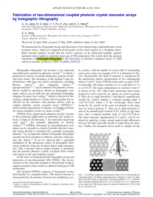
PHYSICAL REVIEW B94,241110(R)(2016)Hubbard band versus oxygen vacancy states in the correlated electron metal SrVO3S.Backes,1T.C.R¨o del,2,3F.Fortuna,2E.Frantzeskakis,2P.Le F`e vre,3F.Bertran,3M.Kobayashi,4R.Yukawa,4 T.Mitsuhashi,4M.Kitamura,4K.Horiba,4H.Kumigashira,4R.Saint-Martin,5A.Fouchet,6B.Berini,6Y.Dumont,6A.J.Kim,1F.Lechermann,7,8H.O.Jeschke,1M.J.Rozenberg,9R.Valent´ı,1,*and A.F.Santander-Syro2,†1Institut f¨u r Theoretische Physik,Goethe-Universit¨a t Frankfurt,Max-von-Laue-Strasse1,60438Frankfurt am Main,Germany 2CSNSM,Univ.Paris-Sud,CNRS/IN2P3,Universit´e Paris-Saclay,91405Orsay Cedex,France3Synchrotron SOLEIL,L’Orme des Merisiers,Saint-Aubin-BP48,91192Gif-sur-Yvette,France 4Photon Factory,Institute of Materials Structure Science,High Energy Accelerator Research Organization(KEK),1-1Oho,Tsukuba305-0801,Japan5SP2M-ICMMO-UMR-CNRS8182Universit´e Paris-Sud,Universit´e Paris-Saclay,91405Orsay Cedex,France 6GEMaC,Universit´e de Versailles St.Quentin en Y.-CNRS,Universit´e Paris-Saclay,Versailles,France7Institut f¨u r Theoretische Physik,Universit¨a t Hamburg,Jungiusstrasse9,20355Hamburg,Germany8Institut f¨u r Keramische Hochleistungswerkstoffe,TU Hamburg-Harburg,D-21073Hamburg,Germany 9Laboratoire de Physique des Solides,CNRS,Univ.Paris-Sud,Universit´e Paris-Saclay,91405Orsay Cedex,France(Received22February2016;published19December2016)We study the effect of oxygen vacancies on the electronic structure of the model strongly correlatedmetal SrVO3.By means of angle-resolved photoemission spectroscopy(ARPES)synchrotron experiments,we investigate the systematic effect of the UV dose on the measured spectra.We observe the onset of a spuriousdose-dependent prominent peak at an energy range where the lower Hubbard band has been previously reportedin this compound,raising questions on its previous interpretation.By a careful analysis of the dose-dependenteffects we succeed in disentangling the contributions coming from the oxygen vacancy states and from the lowerHubbard band.We obtain the ARPES spectrum in the limit of a negligible concentration of vacancies,wherea clear signal of a lower Hubbard band remains.We support our study by means of state-of-the-art ab initiocalculations that include correlation effects and the presence of oxygen vacancies.Our results underscore therelevance of potential spurious states affecting ARPES experiments in correlated metals,which are associatedwith the ubiquitous oxygen vacancies as extensively reported in the context of a two-dimensional electron gas atthe surface of insulating d0transition metal oxides.DOI:10.1103/PhysRevB.94.241110Introduction.A major challenge of modern physics is to understand the fascinating phenomena in strongly correlated transition metal oxides(TMOs),which emerge in the neighbor-hood of the Mott insulator state.Some preeminent examples that have gathered interest for almost30years are high temperature superconductivity,colossal magnetoresistance, heavy fermion physics,and,of course,the Mott metal-insulator transition itself[1].Significant theoretical progress was made with the introduction of dynamical meanfield theory (DMFT)and its combination with ab initio density functional methods[local density approximation(LDA)+DMFT],which allows treatment of the interactions promoting itinerancy and localization of electrons on equal footing[2–4].Among the most emblematic achievements of DMFT is the prediction of a Hubbard satellite,which separates from the conduction band of a metal.This satellite results from the partial localization of conduction electrons due to their mutual Coulomb repulsion. Early DMFT studies also showed that it is the precursor of the localized electronic states of a Mott insulator[5].Since then,these predictions promoted a large number of studies using photoemission spectroscopy,which is a technique to directly probe the presence of Hubbard bands.In this context, the TMO system SrVO3has emerged as the drosophila model system to test the predictions of strongly correlated electron *valenti@itp.uni-frankfurt.de†andres.santander@csnsm.in2p3.fr theories.In fact,SrVO3is arguably the simplest correlated metal.It is a simple cubic perovskite,with nominally one electron per V site,which occupies a threefold degenerate t2g conduction band.While the presence of a satellite in the photoemission spectra of Ni metal was already well known,in the context of correlated TMOs,the Hubbard band was originally reported in a systematic investigation of Ca1−x Sr x VO3[6],which was followed by many subsequent studies,including angle-resolved photoemission spectroscopy (ARPES)[7–9]and comparisons with theoretical predictions (see,for instance,Refs.[10–20],among others).One of the most salient features in SrVO3is the observation of a broad peak at an energy of about−1.5eV in angle integrated photoemission spectra(upper black curve in Fig.1), which is interpreted as a Hubbard satellite linked to the V t2g electrons.This feature is also seen in a large range of 3d1materials[21,22].The ratio of spectral strength between the quasiparticle(QP)state and the incoherent satellite in SrVO3is an important indicator of the magnitude of electron correlations[1,2].However,photoemission experiments using different photon energies or light brilliance have reported very dissimilar values for such a ratio[11],making the quantitative benchmarking of realistic ab initio theories for correlated electron systems difficult[6,11,18,23,24].Moreover,as shown in Fig.1,a broad peak at about the same energy is also observed in several d0TMO cubic perovskites,such as SrTiO3, KTaO3,or anatase TiO2.Nevertheless,in all these cases the feature has been clearly linked to the presence of oxygenS.BACKES et al.PHYSICAL REVIEW B94,241110(R)(2016)FIG.1.Integrated UV photoemission spectra for various per-ovskite oxides,showing a quasiparticle peak at E F and an in-gap state at energies between1and1.5eV.For SrVO3(upper black curve),a correlated-electron metal,the QP peak corresponds to the bulk conduction band,and as will be shown further,the in-gap state is a superposition of the lower Hubbard band and localized electronic states associated with oxygen vacancies.For the other d0 oxides,such as KTaO3(blue curve),anatase TiO2(green curve), or SrTiO3(red curve),the QP peak and in-gap state correspond respectively to a confined quasi-2D electron gas at the sample surface and to localized states,all formed by oxygen vacancies.The crystal orientation(normal to the samples’surface)is indicated in all cases. defects[25–32].Interestingly,recent ab initio calculations show that the spectral weight at−1.3eV in SrTiO3most likely is not of Ti t2g orbital character,but should be understood as an in-gap defect state with Ti e g character[33–36].Thus,we are confronted with the fact that at about1.5eV below the Fermi level(E F),wefind the lower Hubbard bands of d1systems as well as the in-gap states of oxygen-deficient d0systems.In view of these observations one may unavoidably wonder(and worry),despite the great success of DMFT methods,whether the putative Hubbard satellite of SrVO3might also originate from oxygen vacancy states.Moreover,one should also worry about the possibility of these extrinsic states affecting the features of the conduction band dispersion.In the present Rapid Communication we resolve these issues in a thorough manner.We present a systematic photoemission study of SrVO3,to demonstrate dramatic consequences in the spectra due to the creation of oxygen ing ARPES,we directly show that the UV or x-rays used for measurements can produce a large enhancement, of almost an order of magnitude,of the peak at−1.5eV, similar to the effect observed in d0oxide insulators[25–28,37].Despite these significant effects on the energy states around the Mott-Hubbard band,we are able to determine the bulk SrVO3photoemission spectrum in the limit of a negligible concentration of vacancies,where a clear signal of the dispersive correlated Hubbard band remains.We support the interpretation of the experimental data by means of state-of-the-art LDA+DMFT calculations on SrVO3with oxygen vacancies.Consistent with our experimental data,the calculations show that oxygen vacancies produce states(of e g symmetry)at energies near the Hubbard satellite.While our study provides definite evidence of a correlated Hubbard band in SrVO3as predicted by DMFT,it also underlines the significant effects due to oxygen vacancies,which may also affect photoemission data in other TMOs.Methods.The bulk-like relaxed,crystalline(001)oriented SrVO3thinfilms were grown by pulsed laser deposition (PLD)either at the GEMaC laboratory,then measured at the CASSIOPEE beamline of Synchrotron SOLEIL,or in a PLD chamber directly connected to the ARPES setup at beamline2A of KEK-Photon Factory(KEK-PF)[9,38,39]. To clean the surfaces in UHV prior to ARPES experiments at SOLEIL,the SrVO3thinfilms were annealed at550◦C for t=5–20min at pressures lower than2×10−8Torr.At KEK-PF,the PLD growth was performed under a pressure below10−7Torr,to obtain UHV-clean surfaces,using a Sr2V2O7target,which has excess oxygen with respect to SrVO3,thus minimizing the formation of vacancies during the growth.In all cases,the surface quality was confirmed right before ARPES measurements by low-energy electron diffraction(LEED).The thinfilms measured at KEK-PF showed a c(4×4)surface reconstruction,which does not affect the analysis and conclusions of this work.For the ARPES measurements we used linearly polarized photons in the energy range30–110eV and hemispherical electron analyzers with vertical slits at SOLEIL and horizontal slits at KEK-PF.The angular and energy resolutions were0.25◦and 15meV.The mean diameter of the incident photon beam was smaller than100μm.The UV light brilliance,measured using calibrated photodiodes,was≈5×10⁹photons s−1μm−2at SOLEIL,and about100times smaller at KEK-PF.The samples were cooled down to T=20K before measuring.Unless specified otherwise,all data were taken at that temperature. The results were reproduced on more thanfive samples.All through this Rapid Communication,directions and planes are defined in the cubic unit cell of SrVO3.We denote [hkl]the crystallographic directions in real space, hkl the corresponding directions in reciprocal space,and(hkl)the planes orthogonal to those directions.The indices h,k,and l of hkl correspond to the reciprocal lattice vectors of the cubic unit cell of SrVO3.The Supplemental Material[40]presents further details about the sample growth and measurements.Experimental results.Figure2(a)shows the integrated photoemission spectra of SrVO3as a function of the UV dose, measured at CASSIOPEE SOLEIL under the same conditions of light brilliance of any standard ARPES experiment at a third-generation synchrotron.The measurements were done by continuously irradiating the sample with hν=33eV photons while recording the spectra as a function of irradiation time, with an accumulation time of about2min per spectrum.The blue and black curves show spectra for the lowest and highest measured doses,obtained respectively after∼2min and∼2h of irradiation.These data clearly demonstrate that the very UV or x-rays used for photoemission experiments can produce radical changes in the measured spectra of SrVO3.Note in fact that a similar effect has been observed for VO2[41].In particular,from Fig.2(a)we observe that the amplitude ofHUBBARD BAND VERSUS OXYGEN V ACANCY STATES IN THE...PHYSICAL REVIEW B94,241110(R)(2016)FIG.2.(a)Photoemission spectra of SrVO3as a function of UV dose,measured at Synchrotron SOLEIL(hν=33eV).The energy distribution curves(EDCs)were extracted from raw ARPES data around the 002point integrated along the k= 010 direction.(b)Corresponding momentum distribution curves(MDCs)integrated over50meV below E F.Peaks in the MDCs indicate the Fermi momenta.(c),(d)Same as(a),(b)for SrTiO3(hν=47eV).Thefilling of a2DEG upon UV irradiation is evidenced by the formation of QP peaks in the EDCs and MDCs at E F[inset of(c)and(d),respectively].All data were taken at20K.the in-gap state at−1.5eV,and,more significantly,the ratio of in-gap to quasiparticle(QP)amplitudes,strongly increase with increasing UV dose,going from about1:3in a pristine sample to more than2:1in a heavily irradiated sample. Importantly,note that the QP peak position remains basically dose independent,implying that the carriers created by the UV or x irradiation do not significantly dope the conduction band,and form dominantly localized states.This is confirmed in Fig.2(b),which shows that the Fermi momenta of the QP band,given by the peak positions in the momentum distribution curves(MDCs)at E F,are also dose independent. Additional data presented in the Supplemental Material further demonstrate that our measurements yield the expected3D bulk Fermi surface of SrVO3.Thus,the observed increase in intensity of the in-gap state upon UV irradiation cannot be ascribed to a change infilling of the conduction band,which could have affected the electron correlations.Instead,this unambiguously shows the light-assisted formation of localized defect states at essentially the same energy as that of the expected intrinsic lower Hubbard band—which should then resemble the in-gap peak observed at the lowest UV doses.In fact,as mentioned previously,it is well established that strong doses of UV or x-rays create a large concentration of oxygen vacancies in several d0perovskites[25–32,42]. As illustrated in Figs.2(c)and2(d)for the case of SrTiO3, the progressive doping of the surface region with oxygen vacancies,due to synchrotron UV irradiation,has two effects: the formation of a very intense in-gap state at about−1.3eV, and,in contrast to SrVO3,the simultaneous creation of a sharp QP peak at E F corresponding to a confined quasi-2D electron gas(2DEG)at the samples’surface.The effective mass of such2DEG,precisely determined by ARPES,matches the mass expected from density functional theory calcula-tions[25,26,43,44].Thus,as in SrVO3,the increase in intensityof the in-gap state observed in SrTiO3upon UV or x irradiationcannot be due to an onset or increase of electron correlations,and should be ascribed to an extrinsic effect.We therefore conclude that,in SrVO3,exposure to syn-chrotron UV or x-rays creates oxygen vacancies,which are inturn responsible for the extrinsic increase in intensity of thein-gap state evidenced by our measurements.This effect canseriously obscure the determination of the spectral function ofthis model system,thus hampering the advancement of validtheories for correlated electron systems.Thefindings described above imply that the correct ex-perimental determination of the vacancy-free photoemissionspectrum of SrVO3should(i)use samples that from thebeginning have the lowest possible concentration of oxygenvacancies,and(ii)use doses of UV or x-ray light low enoughto avoid light-induced changes in the measured spectra.Tothis end,we measured SrVO3thinfilms grown directly insitu at beamline2A of KEK-PF.As mentioned before,the growth protocol of such thinfilms minimizes the formationof vacancies,while the UV light brilliance at KEK-PF is ∼100times smaller than the one in Figs.2(a)and2(b)from measurements at SOLEIL.We checked(see the SupplementalMaterial)that under these conditions the spectra did notchange with time,even after several hours of measurements.The resulting energy-momentum ARPES map,and its secondderivative,are presented in Figs.3(a)and3(b).One clearlyobserves the dispersing QP band along with an also dispersivein-gap state of weaker intensity,corresponding to the intrinsiclower Hubbard band,as reported in previous works[7].Theintrinsic spectral function of SrVO3will then be given by such aphotoemission spectrum,which approaches the vacancy-freelimit,modulo dipole-transition matrix elements,inherent toS.BACKES et al.PHYSICAL REVIEW B94,241110(R)(2016)FIG.3.(a)Energy-momentum ARPES intensity map measured at KEK-PF with a low UV dose on a SrVO3sample prepared in situ,using a well-established protocol to minimize the formation of oxygen vacancies(see the main text and Supplemental Material).Note that due to the choice of light polarization,the heavy bands along(100)are not observed and only the contribution of the light d xy band is detected.The data were acquired at hν=88eV around ¯103.(b)Second derivative(negative values)of the map in(a).The use of second derivatives allows a better visualization of the dispersion of both the quasiparticle and Mott-Hubbard bands on the same color plot.The dispersionless feature at E F is a spurious effect of such a second derivative on the Fermi-Dirac cutoff.(c),(d)Same as(a),(b)after a strong UV irradiation dose,measured at SOLEIL(hν=33eV),typical of modern third-generation synchrotrons.The measurements were done at hν=33eV close to 002.All data were taken at20K.Note that at constant photon energy,ARPES maps out the electronic structure at a spherical surface of three-dimensional (3D)k space,which can be locally approximated to a plane for all our measurements(details in the Supplemental Material).The different choice of photon energies and k-space positions for measurements at KEK-PF[(a)and(b)]and SOLEIL[(c)and(d)]was dictated by the different geometrical configurations and constraints of the beamlines in both synchrotrons.the photoemission process,which can still modulate the intensity of the QP peak relative to the Hubbard peak.A calculation of such matrix elements requires a full one-step calculation of the photoemission process,which is beyond the scope of this work.By contrast,Figs.3(c)and3(d) show the momentum-resolved electronic structure of a sample, measured at SOLEIL,that was intensively irradiated.There, the peak at−1.5eV becomes broader,more intense,and nondispersive—all characteristic signatures of a high random concentration of oxygen vacancies.Numerical calculations.To rationalize from a microscopic point of view the influence of oxygen vacancies on the electronic structure of SrVO3,we performed charge self-consistent LDA+DMFT calculations for bulk SrVO3and var-ious relaxed oxygen-deficient SrVO3supercells.The latter are computationally demanding calculations.We shall focus here on the case of a2×2×3supercell with two oxygen vacancies located at opposite apical sites of one vanadium atom,as shown in the inset of Fig.4(b).We use such a vacancy arrangement as it is the prototypical one for d0compounds[43].For our LDA+DMFT calculations we chose values of U= 2.5eV and J=0.6eV for vanadium and included the effects of bandwidth renormalization due to dynamically screened Coulomb interactions by following the prescription suggested in Ref.[45](the LDA+DMFT unrenormalized data are shown in the Supplemental Material).In Figs.4(a)and4(c)we show, respectively,the results of the k-integrated and k-resolved spectral functions for bulk SrVO3without oxygen vacancies. Wefind the expected features of a t2g quasiparticle peak at the Fermi level and a lower Hubbard band at negative energies of the same t2g nature,in agreement with the photoemission spectra in Fig.2(a)and Figs.3(a)and3(b).The light band at E F along k 100 [Fig.4(c)]consists of two degenerate bands of d xy and d xz characters,while the heavy band along the same direction has d yz character.While comparing with the measured k-resolved spectral function[Figs.3(a)and3(b)],HUBBARD BAND VERSUS OXYGEN V ACANCY STATES IN THE...PHYSICAL REVIEW B94,241110(R)(2016)FIG.4.LDA+DMFT results for SrVO3including bandwidth renormalization effects[45].(a)k-integrated spectral function for bulk SrVO3.The V t2g orbitals show a quasiparticle peak at E F and a lower Hubbard band at−1.6eV.(b)Spectral function for the2×2×3supercell of SrVO3with two oxygen vacancies.An additional nondispersive V e g vacancy state originating from the V atom neighboring the oxygen vacancies leads to a sharp peak below the Fermi level at∼−1.0eV.The V t2g orbitals show a quasiparticle peak at E F and a lower Hubbard band at−1.8eV.(c)and(d)show the corresponding spectral functions(multiplied by a Fermi-Dirac function at20K)along the X- -X path.one should bear in mind that along -X(or -Y)the heavy d yz(or d xz)bands are silenced by dipole-transition selection rules in the experiment[25].Inclusion of bandwidth renormalization[45]renders the lower Hubbard band at an energy(−1.6eV)in reasonable agreement with experiment (−1.5eV).We adopted typical values for U and J from the literature.We did not attempt to further optimize the values to get a better quantitative agreement with the experimental data, for two reasons:First is the heavy numerical cost,and second, as we show next in the calculations with oxygen vacancies, the adopted values facilitate the distinct visualization of the contributions from the Hubbard and localized states to the incoherent peak at∼−1.5eV.The removal of oxygen atoms in the system leads to the donation of two electrons per oxygen to its surrounding. Already at the level of density functional theory(DFT)in the local density approximation(LDA)(see the Supplemental Material),wefind that most of the charge coming from the additional electrons is transferred to the3d z2orbitals of the neighboring V atom,developing into a sharp peak of e g symmetry located around−1.0eV,i.e.,at an energy close to the position of the experimentally observed oxygen vacancy states.In analogy to the experimental average over many lattice sites,note that averaging among various supercells with differentoxygen vacancy locations and concentrations(which is beyondthe scope of the present work)would result in a wider in-gape g band,as demonstrated for the case of SrTiO3(see Fig.3ofRef.[34])and for some cases in SrVO3(see the SupplementalMaterial,Fig.S7).By including electronic correlations within(bandwidth renormalized)LDA+DMFT we then see that allthe experimental observations qualitatively emerge.In fact,the conducting t2g orbitals develop a lower Hubbard bandpeaked at energies about−1.8eV[Figs.4(b)and4(d)],similarto the bulk case without oxygen vacancies.Most notably,this lower Hubbard satellite does not increase in amplitudewith the introduction of vacancies,but rather broadens.Inaddition,the oxygen vacancy defect states situated at about −1eV remain qualitatively unchanged by the correlation effects,but experience a broadening with respect to the pureLDA case.This is in agreement with the photoemission data,evidencing that the increase in intensity of the in-gap statein the oxygen-deficient SrVO3is not to be attributed to anincrease in population of the lower Hubbard satellite,butinstead to the manifestation of vacancy states of e g character.Conclusions.In summary,we performed a detailed study of the effects of oxygen vacancies in the spectroscopy of the archetypal strongly correlated electron system SrVO3.We found that oxygen vacancy states,which are created by UV or x-ray irradiation,occur at energies close to the Hubbard satellite.This dramatically affects the measured line shape of the Mott-Hubbard band and the ratio of intensities between the quasiparticle and the Mott-Hubbard peaks.By means of a systematic study under a controlled irradiation dose, using samples directly grown in situ,we were able to obtain the photoemission spectrum of the bulk SrVO3system in the limit of a negligible concentration of oxygen vacancies. Our experimental interpretation is supported by LDA+DMFT calculations,which provided further insight into the likely nature of the oxygen vacancy states.Acknowledgments.We thank Silke Biermann,Ralph Claessen,Marc Gabay,and Michael Sing for discussions. This work was supported by public grants from the French National Research Agency(ANR),project LACUNES No. ANR-13-BS04-0006-01,and the“Laboratoire d’Excellence Physique Atomes Lumi`e re Mati`e re”(LabEx PALM project ELECTROX)overseen by the ANR as part of the“Investisse-ments d’Avenir”program(reference:ANR-10-LABX-0039). S.B.,A.J.K.,F.L.,H.O.J.,and R.V.gratefully acknowledge the Deutsche Forschungsgemeinschaft forfinancial support through Grant FOR1346.T.C.R.acknowledges funding from the RTRA–Triangle de la Physique(project PEGASOS).A.F.S.-S.is thankful for support from the Institut Universitairede France.S.B.and T.C.R.contributed equally to this work.[1]M.Imada,A.Fujimori,and Y.Tokura,Metal-insulator transi-tions,Rev.Mod.Phys.70,1039(1998).[2]A.Georges,G.Kotliar,W.Krauth,and M.J.Rozenberg,Dynamical meanfield theory of strongly correlated electronsS.BACKES et al.PHYSICAL REVIEW B94,241110(R)(2016)and the limit of infinite dimensions,Rev.Mod.Phys.68,13 (1996).[3]G.Kotliar and D.V ollhardt,Strongly correlated materials:Insights from dynamical mean-field theory,Phys.Today57(3), 53(2004).[4]G.Kotliar,S.Y.Savrasov,K.Haule,V.S.Oudovenko,O.Parcollet,and C.A.Marianetti,Electronic structure calculations with dynamical mean-field theory,Rev.Mod.Phys.78,865 (2006).[5]X.Y.Zhang,M.J.Rozenberg,and G.Kotliar,Mott Transitionin the d=∞Hubbard Model at Zero Temperature,Phys.Rev.Lett.70,1666(1993).[6]I.H.Inoue,I.Hase,Y.Aiura,A.Fujimori,Y.Haruyama,T.Maruyama,and Y.Nishihara,Systematic Development of the Spectral Function in the3d1Mott-Hubbard System Ca1−x Sr x VO3,Phys.Rev.Lett.74,2539(1995).[7]M.Takizawa,M.Minohara,H.Kumigashira,D.Toyota,M.Oshima,H.Wadati,T.Yoshida,A.Fujimori,M.Lippmaa,M.Kawasaki,H.Koinuma,G.Sordi,and M.Rozenberg,Coherent and incoherent d band dispersions in SrVO3,Phys.Rev.B80, 235104(2009).[8]T.Yoshida,M.Hashimoto,T.Takizawa,A.Fujimori,M.Kubota,K.Ono,and H.Eisaki,Mass renormalization in the bandwidth-controlled Mott-Hubbard systems SrVO3and CaVO3studied by angle-resolved photoemission spectroscopy,Phys.Rev.B 82,085119(2010).[9]S.Aizaki,T.Yoshida,K.Yoshimatsu,M.Takizawa,M.Minohara,S.Ideta,A.Fujimori,K.Gupta,P.Mahadevan,K.Horiba,H.Kumigashira,and M.Oshima,Self-Energy on the Low-to High-Energy Electronic Structure of Correlated Metal SrVO3,Phys.Rev.Lett.109,056401(2012).[10]M.J.Rozenberg,I.Inoue,H.Makino,F.Iga,and Y.Nishihara,Low Frequency Spectroscopy of the Correlated Metallic System Ca1−x Sr x VO3,Phys.Rev.Lett.76,4781(1996).[11]A.Sekiyama,H.Fujiwara,S.Imada,S.Suga,H.Eisaki,S.I.Uchida,K.Takegahara,H.Harima,Y.Saitoh,I. A.Nekrasov,G.Keller,D.E.Kondakov,A.V.Kozhevnikov,Th.Pruschke,K.Held,D.V ollhardt,and V.I.Anisimov,Mutual Experimental and Theoretical Validation of Bulk Photoemis-sion Spectra of Sr1−x Ca x VO3,Phys.Rev.Lett.93,156402 (2004).[12]E.Pavarini,S.Biermann,A.Poteryaev,A.I.Lichtenstein,A.Georges,and O.K.Andersen,Mott Transition and Suppression of Orbital Fluctuations in Orthorhombic3d1Perovskites,Phys.Rev.Lett.92,176403(2004).[13]B.Amadon,F.Lechermann,A.Georges,F.Jollet,T.O.Wehling,and A.I.Lichtenstein,Plane-wave based electronic structure calculations for correlated materials using dynamical mean-field theory and projected local orbitals,Phys.Rev.B77,205112 (2008).[14]M.Aichhorn,L.Pourovskii,V.Vildosola,M.Ferrero,O.Parcollet,T.Miyake,A.Georges,and S.Biermann,Dynamical mean-field theory within an augmented plane-wave framework: Assessing electronic correlations in the iron pnictide LaFeAsO, Phys.Rev.B80,085101(2009).[15]M.Karolak,T.O.Wehling, F.Lechermann,and A.I.Lichtenstein,General DFT++method implemented with pro-jector augmented waves:Electronic structure of SrVO3and the Mott transition in Ca2−x Sr x RuO4,J.Phys.:Condens.Matter23, 085601(2011).[16]H.Lee,K.Foyevtsova,J.Ferber,M.Aichhorn,H.O.Jeschke,and R.Valent´ı,Dynamical cluster approximation within an aug-mented plane wave framework:Spectral properties of SrVO3, Phys.Rev.B85,165103(2012).[17]J.M.Tomczak,M.Casula,T.Miyake, F.Aryasetiawan,and S.Biermann,Combined GW and dynamical mean-field theory:Dynamical screening effects in transition metal oxides, Europhys.Lett.100,67001(2012).[18]C.Taranto,M.Kaltak,N.Parragh,G.Sangiovanni,G.Kresse,A.Toschi,and K.Held,Comparing quasiparticle GW+DMFTand LDA+DMFT for the test bed material SrVO3,Phys.Rev.B 88,165119(2013).[19]J.M.Tomczak,M.Casula,T.Miyake,and S.Biermann,Asymmetry in band widening and quasiparticle lifetimes in SrVO3:Competition between screened exchange and local correlations from combined GW and dynamical mean-field theory GW+DMFT,Phys.Rev.B90,165138(2014).[20]A.van Roekeghem and S.Biermann,Screened exchangedynamical meanfield theory and its relation to density functional theory:SrVO3and SrTiO3,Europhys.Lett.108,57003(2014).[21]A.Fujimori,I.Hase,H.Namatame,Y.Fujishima,Y.Tokura,H.Eisaki,S.Uchida,K.Takegahara,and F.M.F.de Groot,Evolution of the Spectral Function in Mott-Hubbard Systems with d1Configuration,Phys.Rev.Lett.69,1796(1992). [22]K.Morikawa,T.Mizokawa,A.Fujimori,Y.Taguchi,andY.Tokura,Photoemission spectral weight distribution in Y1−x Ca x TiO3,Phys.Rev.B54,8446(1996).[23]I.A.Nekrasov,G.Keller,D.E.Kondakov,A.V.Kozhevnikov,Th.Pruschke,K.Held, D.V ollhardt,and V.I.Anisimov, Comparative study of correlation effects in CaVO3and SrVO3, Phys.Rev.B72,155106(2005).[24]R.Eguchi,T.Kiss,S.Tsuda,T.Shimojima,T.Mizokami,T.Yokoya,A.Chainani,S.Shin,I.H.Inoue,T.Togashi,S.Watanabe,C.Q.Zhang,C.T.Chen,M.Arita,K.Shimada,H.Namatame,and M.Taniguchi,Bulk-and Surface-SensitiveHigh-Resolution Photoemission Study of Two Mott-Hubbard Systems:SrVO3and CaVO3,Phys.Rev.Lett.96,076402 (2006).[25]A.F.Santander-Syro,O.Copie,T.Kondo,F.Fortuna,S.Pailh`e s,R.Weht,X.G.Qiu,F.Bertran,A.Nicolaou,A.Taleb-Ibrahimi, P.Le F`e vre,G.Herranz,M.Bibes,N.Reyren,Y.Apertet,P.Lecoeur,A.Barth´e l´e my,and M.J.Rozenberg,Two-dimensional electron gas with universal subbands at the surface of SrTiO3, Nature(London)469,189(2011).[26]W.Meevasana,P.D.C.King,R.H.He,S.-K.Mo,M.Hashimoto,A.Tamai,P.Songsiriritthigul,F.Baumberger,and Z.-X.Shen,Creation and control of a two-dimensional electron liquid at the bare SrTiO3surface,Nat.Mater.10,114(2011).[27]P.D.C.King,R.H.He,T.Eknapakul,P.Buaphet,S.-K.Mo,Y.Kaneko,S.Harashima,Y.Hikita,M.S.Bahramy,C.Bell,Z.Hussain,Y.Tokura,Z.-X.Shen,H.Y.Hwang,F.Baumberger, and W.Meevasana,Subband Structure of a Two-Dimensional Electron Gas Formed at the Polar Surface of the Strong Spin-Orbit Perovskite KTaO3,Phys.Rev.Lett.108,117602 (2012).[28]T.C.R¨o del,F.Fortuna,F.Bertran,M.Gabay,M.J.Rozenberg,A.F.Santander-Syro,and P.Le F`e vre,Engineering of two-dimensional electron gases at the(001)and(101)surfaces of TiO2anatase using light,Phys.Rev.B92,041106(R) (2015).。
2020年12月第12期(总267)铁道工程学报JOURNAL OF RAILWAY ENGINEERING SOCIETYDec2020NO.12(Ser.267)文章编号:1006-2106(2020)12-0064-06基于声子晶体理论进行轨道系统减振效果研究李粮余杯(中铁二院工程集团有限责任公司,成都610031)摘要:研究目的:针对高速铁路下穿机场航站楼引起的振动噪声问题,分析传统轨道减振技术针对高铁下穿航站楼时存在的弊端,基于声子晶体理论,引入新型声子晶体减振垫层,以降低60~80Hz特殊频段的振动水平,减少列车运行对机场航站楼内人员的影响。
本文以成都至自贡高铁线下穿天府机场航站楼为例,采用多刚体动力学软件UM(Universal Mechanism)与有限元软件ANSYS联合仿真,通过建立两种不同下部基础的列车-轨道-隧道刚柔耦合动力学模型,对新型声子隔振垫和普通隔振垫的减振效果进行对比分析,验证新型声子减振垫的减振效果。
研究结论:(1)基于声子晶体局域共振禁带机理设计的新型声子晶体隔振垫轨道各结构低频范围的振动峰值有所减小,且在特定频段(63~100Hz)减振性能更为显著,其中在80Hz频段范围减振效果最佳,较普通隔振垫减小9.9dB,在高铁下穿航站楼时具有良好的减振效果;(2)本研究成果可用于临近或下穿机场及特殊建筑时的高速铁路无祚轨道减振降噪。
关键词:高速铁路;航站楼;声子晶体;隔振垫中图分类号:U213.2+44文献标识码:AResearch on the Vibration Reduction Effect of Track System Based on Phononic Crystal TheoryLI Liangyu(China Railway Eryuan Engineering Group Co.Ltd,Chengdu,Sichuan610031,China)Abstract:Research purposes:Aiming at the problem of vibration and noise caused by high一speed railway crossing airport terminal,this paper analyzes the disadvantages of traditional track vibration reduction technology in high一speed railway crossing terminal.Based on phononic crystal theory,a new phononic crystal damping pad is introduced to reduce the vibration level of60〜80Hz and the influence of train operation on people in the airport terminal.Taking the Chengdu-Zigong high-speed railway line passing through the Tianfu airport terminal as an example,the multi一rigid body dynamics software UM(Universal Mechanism)and the finite element software ANSYS are used to the simulation. By establishing two train—track一tunnel rigid一 flexible coupling dynamics models of different foundation,the vibration absorption effect of the new phononic damping pad and the ordinary damping pad is compared and analyzed to verify the vibration absorption effect of the new phononic cushion.Research conclusions:(1)The vibration peak value of the low frequency range of each structure of the track that used new phononic crystal damping pad based on the local resonance band gap mechanism of phononic crystals is reduced, and the vibration absorption perfoimance is more significant in the specific frequency band(63〜100Hz).The damping*收稿日期:2020-10-15基金项目:四川省重点研发项目——川藏铁路重大工程风险识别与对策研究(2019YFG0460)**作者简介:李粮余,1982年出生,男,高级工程师,现任中铁二院工程集团有限责任公司土建二院轨道处副处长。
![二维光子晶体波导的能带分析[1]](https://uimg.taocdn.com/ebcae81ba8114431b90dd8cd.webp)
二维材料声子谱二维材料的声子谱是描述材料中原子振动模式的重要工具。
声子谱可以提供关于材料热力学性质、热传导性质、力学性质以及电子-声子相互作用等方面的关键信息。
在二维材料中,声子谱的研究对于理解材料的物理和化学性质以及开发新型电子和光电器件具有重要意义。
要计算二维材料的声子谱,通常需要使用基于密度泛函微扰理论(DFPT)的方法,如使用Phonopy 或Quantum ESPRESSO 等软件包进行计算。
这些软件包可以通过对晶体结构进行优化和处理,计算出不同振动模式下的声子频率和波矢,从而得到声子谱。
在计算二维材料的声子谱时,需要注意一些特殊的考虑因素。
首先,由于二维材料的原子层数较少,层间相互作用对于声子谱的影响可能较为显著。
因此,在计算中需要考虑层间相互作用对于原子振动模式的影响。
其次,由于二维材料可能存在褶皱、弯曲等形貌变化,这些变化也可能对声子谱产生影响。
因此,在计算中需要考虑材料的形貌变化对于声子谱的影响。
二维材料的声子谱通常具有一些独特的特征。
例如,在石墨烯等二维材料中,存在特殊的振动模式,如ZA模式(垂直于平面的弯曲模式)和ZO模式(面内剪切模式)。
这些模式在声子谱中具有特殊的分布和频率范围,对于理解材料的物理和化学性质具有重要意义。
此外,二维材料的声子谱还可以提供关于材料热力学稳定性和力学性质的信息。
例如,通过计算声子谱中的虚频情况,可以判断材料的结构是否稳定;通过计算声子谱中的弹性常数和声速等参数,可以评估材料的力学性质和机械性能。
总之,二维材料的声子谱是研究材料物理和化学性质的重要工具之一。
通过计算和分析声子谱,可以深入理解二维材料的振动模式、热力学性质、力学性质以及电子-声子相互作用等方面的信息,为开发新型电子和光电器件提供理论支持。

声子晶体中的声子带隙与声子色散声子晶体是一种具有周期性结构的介质,其中声子的传播行为受到了限制和调控。
声子晶体的结构可以导致声子的频率范围被分割成禁带(带隙),而在带隙之外,声子的传播则呈现出特定的色散关系。
声子晶体的研究不仅对于材料科学有着重要的意义,还可以为声子学的发展提供新的思路和实验验证。
声子带隙是指在声子晶体中存在频率范围上的禁带区域,即声子无法在该频率范围内传播。
这种禁带的形成是由于声子晶体的周期性结构导致了声子振动的相互干涉和散射。
当声子频率位于禁带范围内时,它们会发生反射或散射,并无法向晶体内部传播。
这种禁带的产生使得声波在声子晶体中的传播受到限制,导致声学参数的异常变化。
声子带隙的宽度和位置与声子晶体的结构密切相关。
例如,晶格常数的变化、原子质量的改变、晶胞中原子布局的不规则性等都可以导致声子带隙的变化。
此外,声子晶体的拓扑结构也对声子带隙的形成起着决定性的作用。
一些特殊的拓扑结构,如六角形、正方形或三角形的单元结构,可以产生较大的带隙。
研究表明,声子带隙的宽度对声子晶体的声波传播和能量传递有着重要的影响。
与声子带隙相对应的是声子色散关系。
声子色散关系描述了声子的频率与波矢之间的关系,即声子的能量-动量(E-k)关系。
在声子带隙之外,声子色散关系通常是线性的,即声子频率与波矢成正比。
而在声子带隙内,声子的色散关系会显示出非线性的特征。
这种非线性的色散关系使得声子在频率和波矢空间中的传播方式与声子晶体的结构和拓扑特性密切相关。
声子带隙与声子色散关系的研究对于声子学和材料科学的发展具有重要意义。
首先,声子带隙的存在使得声子晶体可以有选择地传播特定频率的声波。
这为制备新型声学器件提供了可能,例如声学滤波器、声学隔离器等。
其次,声子带隙的特性对于材料的声学性能和热学性能有着重要的影响。
通过调控声子带隙的宽度和位置,我们可以优化材料的声学和热学性质,如声速、声传导率等。
最后,声子带隙的研究也可以为设计和制备新型声子晶体提供指导,进一步拓展声子学的研究领域。
Bandstructuresintwo-dimensionalphononiccrystalswithperiodicJerusalemcrossslot
YinggangLia,b,TianningChena,b,n,XiaopengWanga,b,KunpengYua,b,RuifangSonga,baSchoolofMechanicalEngineering,Xi'anJiaotongUniversity,Xi'an710049,PRChina
bStateKeyLaboratoryforStrengthandVibrationofMechanicalStructures,Xi'anJiaotongUniversity,Xi'an710049,PRChina
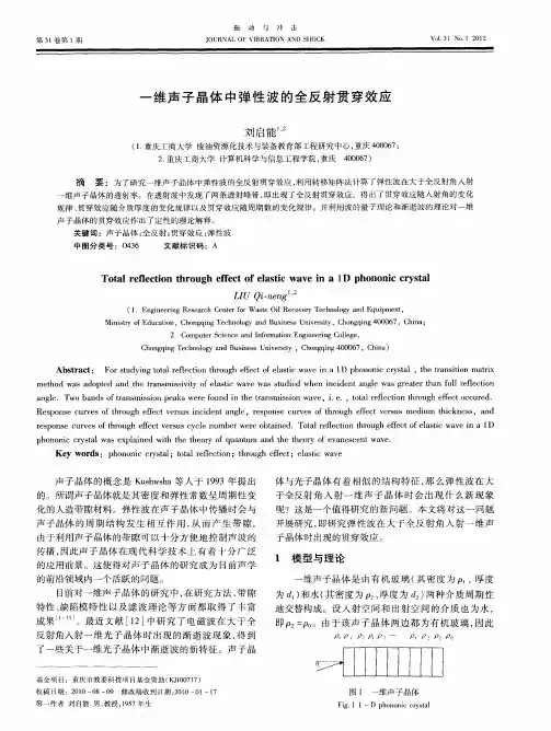
articleinfoArticlehistory:Received28September2013Receivedinrevisedform25July2014Accepted26August2014Availableonline6September2014Keywords:BandgapsJerusalemcrossslotPhononiccrystalsFiniteelementmethodabstractInthispaper,anoveltwo-dimensionalphononiccrystalcomposedofperiodicJerusalemcrossslotinairmatrixwithasquarelatticeispresented.ThedispersionrelationsandthetransmissioncoefficientspectraarecalculatedbyusingthefiniteelementmethodbasedontheBlochtheorem.Theformationmechanismsofthebandgapsareanalyzedbasedontheacousticmodeanalysis.Numericalresultsshowthattheproposedphononiccrystalstructurecanyieldlargebandgapsinthelow-frequencyrange.TheformationmechanismofopeningtheacousticbandgapsismainlyattributedtotheresonancemodesofthecavitiesinsidetheJerusalemcrossslotstructure.Furthermore,theeffectsofthegeometricalparametersonthebandgapsarefurtherexplorednumerically.Resultsshowthatthebandgapscanbemodulatedinanextremelylargefrequencyrangebythegeometryparameterssuchastheslotlengthandwidth.Thesepropertiesofacousticwavesintheproposedphononiccrystalscanpotentiallybeappliedtooptimizebandgapsandgeneratelow-frequencyfiltersandwaveguides.&2014ElsevierB.V.Allrightsreserved.
1.IntroductionOverthelasttwodecades,thepropagationofacousticandelasticwavesinperiodiccompositematerials,knownasphononiccrystals(PCs)hasattractedconsiderableattentionfortheirabun-dantphysicsandpotentialengineeringapplications[1–4].Phono-niccrystalsareperiodicartificialcompositematerialsmadeoftwoormorematerialswithdifferentelasticconstants,andtheycandemonstratevariousnovelphysicalproperties;inparticular,theexistenceofphononicbandgaps(BGs),inwhichthepropagationofelasticwavesisprohibited[5–8].WiththeexistenceofBGs,phononiccrystalspossessextensivepotentialapplications,suchasvibrationandnoisereduction[9–11],soundfilters[12,13]andwaveguides[14,15].EarlierstudieshavedemonstratedthattheoccurrenceoftheBGsisattributedtoBraggscatteringandlocalizedresonances.Forthefirstmechanism,theBGsareattributedtothedestructiveinterferencebetweenincidentacousticwavesandreflectionsfromtheperiodicscatterers.Whenwavelengthsareoftheorderofthelatticeconstants,thephononiccrystalscanyieldcompletepho-nonicBGs[16–18].Forthesecondmechanism,theresonancesof
scatteringunitsplayamajorroleintheBGswhicharelessdependentontheperiodicityandsymmetryofthestructure.ThefrequencyrangeofthegapcouldbealmosttwoordersofmagnitudelowerthantheusualBragggap[19,20].InordertopromotetheengineeringapplicationofPCs,theacquisitionoflargeandtunableBGsatlowfrequenciesisofextremelyimportance.KushwahaandDjafari-Rouhani[21]com-putedextensivebandstructuresforperiodicarraysofrigidmetallicrodsinairandobtainedmultiplecompleteacousticstopbands.Lietal.[22]investigatedtheeffectsoforientationsofsquarerodsontheacousticbandgapsintwo-dimensionalperiodicarraysofrigidsolidrodsembeddedinairandconcludedthattheacousticbandgapscanbeopenedandenlargedgreatlybyincreasingtherotationangle.Chengetal.[23]demonstratedthataclassofultrasonicmetamaterial,whichwascomposedofsubwa-velengthresonantunits,builtupbyparallel-coupledHelmholtzresonatorswithidenticalresonantfrequency,possessedbroadlocallyresonantforbiddenbandsandthebandwidthswerestronglydependentonthenumberofresonatorsineachunit.Lietal.[24]studiedphononicbandstructurewithperiodicellipticinclusionsforthesquarelatticebasedontheplanewaveexpan-sionmethodandthenumericalresultsshowedthesystemscomposedoftungstenellipticrodsembeddedinsiliconmatrixcanexhibitalargercompletebandgapthantheconventionalcircularphononiccrystalslabs.Cuietal.[25]presentedanewbandgapstructurecomposedofasquarearrayofparallelsteel
ContentslistsavailableatScienceDirectjournalhomepage:www.elsevier.com/locate/physbPhysicaB
http://dx.doi.org/10.1016/j.physb.2014.08.0350921-4526/&2014ElsevierB.V.Allrightsreserved.
nCorrespondingauthorat:SchoolofMechanicalEngineering,Xi'anJiaotong
University,Xi'an710049,PRChina.Tel./fax:þ862982665376.E-mailaddress:tnchen@mail.xjtu.edu.cn(T.Chen).
PhysicaB456(2015)261–266