
AASHTO LRFD Guide Specification Pedestrian Bridge Design Example Half-Through Truss Bridge with Tubular Members
ILLUSTRATIVE EXAMPLE OF KEY PROVISIONS OF GUIDE SPECIFICATIONS
Load and Resistance Factor Design
GENERAL INFORMATION
Specifications Used:
- AASHTO LRFD Bridge Design Specifications, 2008 (AASHTO LRFD)
- AASHTO Standard Specificationsfor Structural Supports for
Highway Signs, Luminaires and Traffic Signals, 2008 (AASHTO Signs)
- LRFD Guide Specifications for Pedestrian Bridges (Specification)
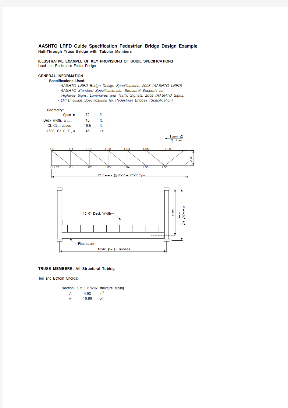
Geometry:
Span =72ft.
Deck width, w deck =10ft.
CL-CL trusses =10.5ft.
TRUSS MEMBERS: All Structural Tubing
Top and Bottom Chords:
Section:6 x 3 x 5/16" structural tubing
A = 4.98in2
w =16.96plf
End Posts:
Section:6 x 3 x 5/16" structural tubing
A = 4.98in2
w =16.96plf
Vertical Posts:
Section:5 x 3 x 5/16" structural tubing
A = 4.36in2
w =14.83plf
I x = I c =13.2in4
Diagonals:
Section:4 x 3 x 1/4" structural tubing
A = 3.09in2
w =10.51plf
FLOORBEAMS:
Section:W8x10
I x = I b =30.8in4
S x =7.81in3
Spacing =6ft. at each panel point
DEAD LOAD:
Weight of each truss =60plf per truss
Assumed deck loading =25psf
Weight of deck & floor system =25 psf x 10.50 ft. / 2
=132plf per truss
Total dead load =60 plf + 132 plf
=192plf Use200plf
PEDESTRIAN LIVE LOAD:(Specification, Article 3.1)
MAIN MEMBERS: Trusses
- Use 90 psf without impact.
Live load per truss =pedestrian loading x deck width / 2
=90 psf x 10.0 ft. / 2=450plf
SECONDARY MEMBERS: Deck, Stringers, Floorbeams
- Use 90 psf without impact.
VEHICLE LOAD:(Specification, Article 3.2)
- Use Table 3.2-1 for Minimum Axle Loads and Spacings.
Use the following vehicle for a clear deck width between 7 ft. and 10 ft.
Front axle =2k Rear axle =8k Axle spacing =14ft.Wheel spacing =
6
ft.
Note:WIND LOAD:
(Specification, Article 3.4)
- Assume 100 mph design wind.
- The design life shall be taken as 50 years for the purpose of calculating the wind loading.
- The deck area may be used to compute design pedestrian live load for all main member components (truss members). The deck area is the non-zero influence surface for all such components.- Vehicular access is not prevented by fixed physical methods, therefore, the pedestrian bridge should be designed for an occassional single maintenance vehicle load.- The vehicular load shall not be placed in combination with the pedestrian load. Consideration of impact is not included with this vehicular loading.
- Neglect wind load on the live load vehicle.
For this example, the pedestrian load controls for the truss design; however, the
vehicle load will control for the floor system design.
- Use wind load as specified in the AASHTO Signs , Articles 3.8 and 3.9.
Horizontal Wind Loading
- Apply the design horizontal wind pressure on the truss components.
P z =design wind pressure on superstructure using AASHTO Signs, Eq. 3-1 or Table 3-7, psf =0.00256K z GV 2I r C d
(AASHTO Signs, Eq. 3-1)
where:
K z =height and exposure factor from AASHTO Signs, Eq. C3-1 or Table 3-5= 1.00(conservatively taken from Table 3-5 for a height of 32.8 ft.)
G =gust effect factor = 1.14(minimum)V =basic wind velocity =100mph
I r =wind importance factor from AASHTO Signs, Table 3-2= 1.00C d =wind drag coefficient from AASHTO Signs, Table 3-6= 2.00
P z =
58.4
psf
Projected vertical area per linear foot: Chords: 2 @ 3 in./ 12 x 6 ft. / 6 ft.0.50SF/ft. Verticals: 3 in./ 12 x 4.75 ft. long / 6 ft.0.20SF/ft. Diagonals: 3 in. x 7.81 ft. long / 6 ft.0.33SF/ft. Total per Truss: 1.03SF/ft. Deck + Stringers:
10" / 12
0.83
SF/ft.
WS H =total horizontal wind on superstructure, plf
=(2 trusses x 1.03 SF/ft. + 0.83 SF/ft.) x 58.4 psf =169plf
Note:(Alternatively, AASHTO Signs, Table 3-7 may be used
with a C d value of 2.0 applied)
The full lateral wind loads must be resisted by the entire superstructure.
Appropriate portions of the design wind loads must also be distributed to the truss top chord for design lateral forces on the truss verticals.
Vertical Wind Loading
WS V ==P v *w deck
where:
P v =vertical wind loading on superstructure, ksf =0.020ksf
w deck =total deck width, ft.=10.0ft.
Therefore,
WS V =0.020 ksf x 1000 x 10.00 ft.
=200plf
Vertical load on leeward truss =200 plf x (7.5 ft. + (0.5 in. + 2.5 in.) / 12) / 10.50 ft.
=147.6plf Vertical load on windward truss =200 plf x (2.5 ft. + (0.5 in. + 2.5 in.) / 12) / 10.50 ft.=52.4plf (uplift)
TOTAL VERTICAL LOADS PER TRUSS:
(Specification, Article 3.7)
DEAD LOAD (DC1+DC2):
200plf LIVE LOAD (Pedestrian, PL):450plf WIND (Overturning, WS):
148
plf
STRENGTH I LIMIT STATE (g DC1+DC2*(DC1+DC2) + g PL *PL)
=1,038plf STRENGTH III LIMIT STATE (g DC1+DC2*(DC1+DC2) + g WS *WS V )=457plf SERVICE I LIMIT STATE (g DC1+DC2*(DC1+DC2) + g PL *PL + g WS *WS V )=694plf
vertical wind load on the full projected area of the superstructure applied at the
windward quarter point, plf
- Apply a vertical pressure of 0.020 ksf over the full deck width concurrently with the horizontal loading.This loading shall be applied at the windward quarter point of the deck width.
TRUSS MEMBER DESIGN LOADS:
Panel point load from controlling load comb. = 1.038 klf x 6.0 ft. panel = 6.23 k/panel Maximum Truss Member Axial Loads (from separate truss analysis): Chord (U05-U06)134.57k (compression) End Post (U00-L00)34.27k (compression) Diagonal (U00-L01)53.52k (tension) Vertical (U01-L01)28.04k (compression)
TRUSS TOP CHORD LATERAL SUPPORT:(Specification, Article 7.1)
- Lateral support is provided by a transverse U-frame consisting of the floorbeam and truss https://www.doczj.com/doc/9416504792.html,pute CL/P c for use in the Table.
where:
C =P/
D =
2.917
k/in.
(from a separate 2D analysis)
L ==72in.
P c ==178.9781k CL/P c =
1.17
n =number of panels =
12
Therefore,
1/K =0.688(Specification, by interpolation of Table 7.1.2-1)
K =
1.45
- Assume the truss verticals are adequate to resist the lateral force per Specification, Article 7.1.1 (Must verify assumption; see section titled "LATERAL FORCE TO BE RESISTED BY VERTICALS")
unbraced length of the chord in compression (i.e. length between panel
points), in.desired critical buckling load (i.e. factored compressive force) multiplied by 1.33, k (Specification, Article 7.1.2)Determine the design effective length factor, K, for the individual top chord members supported between the truss verticals using Specification, Table 7.1.2-1.
TOP CHORD COMPRESSIVE RESISTANCE:(AASHTO LRFD, Article 6.9.2) Check the slenderness ratio against the limiting value.
For main members:KL/r ≤ 120
For bracing members:KL/r ≤ 140
Section:6 x 3 x 5/16" Structural Tube
A = 4.98in2
r x =radius of gyration about the x-axis, in.
= 2.06in.
r y =radius of gyration about the y-axis, in.
= 1.18in.
K = 1.45
L =72in.
KL/r x =(1.45 x 72 in.) / 2.06 in.
=50.8<120OK
KL/r y =(1.00 x 72 in.) / 1.18 in.
=61.0<120OK
P r =factored resistance of components in compression, k
=f c P n(AASHTO LRFD, Eq. 6.9.2.1-1)
where:
f c =resistance factor for compressive per AASHTO LRFD, Article 6.5.4.2
=0.9
P n =nominal compressive resistance per AASHTO LRFD, Article 6.9.4, k
Determine the nominal compressive resistance, P n
If l≤ 2.25, then:
P n = 0.66l F y A s(AASHTO LRFD, Eq. 6.9.4.1-1)
If l > 2.25, then:
P n =(AASHTO LRFD, Eq. 6.9.4.1-2)
l =(AASHTO LRFD, Eq. 6.9.4.1-3)
=0.60
where:
A s =gross cross-sectional area, in 2
= 4.98in 2
F y =specified minimum yield strength, ksi =46ksi E =modulus of elasticity, ksi =29,000ksi KL/r s =Maximum of KL/r x ,KL/r y =61
Therefore, the top chord factored resistance is:
P n =0.660.60 x 46 ksi x 4.98 in 2=178 k f c P n =
160 k
>
P chord =134.57 k
OK
LATERAL FORCE TO BE RESISTED BY VERTICALS:
(Specification, Article 7.1.1)
H f =minimum lateral force, k =0.01/K*P avg where:
K =
1.45
P avg =average design compressive force in adjacent chord members, k =134.57 k Verify limit 0.01 / 1.45 =
0.007
>
0.003
OK
Therefore,
H f =0.01 / 1.45 x 134.57 k =0.93 k
Length of vertical =
54.0
in.
Lateral Moment in Vertical due to C = 0.93 k x 54.0 in. = 50.00 k-in.
Apply H f as the lateral force at the top of the Truss Verticals. Apply H f concurrently with other primary forces in the Verticals (combined compression plus bending analysis). Include lateral wind forces for
AASHTO LRFD Load Combination Strength III.
END POSTS:(Specification, Article 7.1.1)Lateral Force: C = 0.01 x 34.27 k =
0.34 k
Note:All other truss members are analyzed using conventional methods per AASHTO LRFD.
DEFLECTION:
(Specification, Article 5)
Maximum pedestrian LL Deflection = 1/500 of the span length =72.00 ft. x 12 / 500 =
1.73 in.
From Truss Analysis, LL Deflection (w LL = 0.450 k/ft) = 1.20 in.
< L/500OK
VIBRATIONS:(Specification, Article 6)
Vertical Direction
f = 0.18*SQRT(
g / D DL )
where:
g =acceleration due to gravity, ft/s 2=32.2ft/s 2
D DL =maximum vertical deflection of the truss due to the dead load, ft.=0.0444ft.(from a separate analysis with w = 0.20 klf per truss)f = 0.18*SQRT(32.2 / 0.0444) =
4.85 Hz > 3.0 Hz minimum desirable, OK
f ≥ 2.86 ln (180 / W)where:
W ==2 trusses x 0.20 klf x 72.00 ft.=28.8k (Dead Load Only)
2.86 ln (180 / 28.80) =
5.24 Hz
- Estimate the fundamental frequency in the vertical direction, f, by approximating the truss as a simply supported uniform beam:
- The fundamental frequency in a vertical mode without consideration of live load should be greater than 3.0 Hz to avoid the first harmonic.
- Apply the lateral force, C, at the top end of post and design as a cantilever combined with axial load. The lateral force, C, is taken as 1.0% of the end post axial load.
For illustration purposes, assume higher harmonics (second, third, etc.) are a concern. The bridge should
be proportioned such that the following criteria is satisfied:
full weight of the supported structure including dead load and an allowance for actual pedestrian live load, k
f = 4.85 Hz is not greater than 5.24 Hz, include a portion of the pedestrian live load.
Assume some pedestrian live load contribution and re-evaluate the expression:
W = DL + 10%LL = 28.8 + 0.10 x 2 x (0.450 klf x 72.00 ft.) =35.28 k
2.86 ln (180 / 35.28) = 4.66 Hz< f = 4.85 Hz OK
Lateral Direction
- Estimate the fundamental frequency in the lateral direction, f lat, by approximating the truss as a simply supported uniform beam rotated 90 degrees:
- The fundamental frequency in a lateral mode without consideration of live load should be greater than 1.3 Hz to avoid the first harmonic.
Assume the lateral wind bracing is 3 x 3 x 1/4" structural tubing.
f = 0.18*SQRT(
g / D DL_Lat)
where:
g =acceleration due to gravity, ft/s2
=32.2ft/s2
D DL_Lat =maximum lateral deflection of the truss due to the dead load, ft.
=0.0844ft.(from a separate analysis)
f = 0.18*SQRT(32.2 / 0.0844) = 3.52 Hz> 1.3 Hz minimum desirable, OK FATIGUE:(Specification, Article 3.5) Use AASHTO Signs, Article 11.7.3
AASHTO Signs, Article 11.7.4 - Not used as it is assumed that the Pedestrian Bridge
is not over a highway
P NW = 5.2 C d I F
C d =wind drag coefficient per AASHTO Signs, Table 3-6
= 2.00
I F =wind importance factor per AASHTO Signs, Table 3-2
= 1.00
P NW =10.4psf
WS H =total horizontal wind on superstructure, plf
=(2 trusses x 1.03 SF/ft. + 0.83 SF/ft.) x 10.4 psf
=31plf
FATIGUE Cont'd:
Maximum Member Force:
Bottom Chord, Member L05-L06 = 5.6kips(from a separate
Analysis)
Δf =Stress Range
=(5.6 kips / 4.98 in2)
= 1.12in2
γ(Δf ) ≤ (ΔF)n(AASHTO LRFD Eq. 6.6.1.2.2-1) where:
γ = 1.0(Specification, Article 3.7)
Δf = 1.12ksi
(ΔF)n = (ΔF)TH(Specification, Article 4.1)
where
(ΔF)n =16ksi(Category B -base metal)
(AASHTO Signs, Table 11-3)
(1.0)(1.12) ≤ 16
1.12<16OK
Welded Member connections and Fracture Toughness Requirements are outside the limits
of this Pedestrian Bridge design example. They will be the responsibility of the designer.