UBA2071; UBA2071A
Half bridge control IC for CCFL backlighting
Rev. 01 — 23 June 2008Product data sheet
1.General description
The UBA2071 and UBA2071A are high voltage ICs intended to drive Cold Cathode
Fluorescent Lamps (CCFLs) or External Electrode Fluorescent Lamps (EEFLs) for
backlighting applications.They can drive a half bridge circuit made up of two NMOSFETs
with a supply voltage of up to550V,so the inverter can be supplied directly from a400V
PFC bus.
The UBA2071 and UBA2071A contain a controller, a level shifter, a bootstrap diode and
drivers for the external half bridge power switches. It also contains a low frequency PWM
generator,which can be used to control the brightness level of the lamps,using an analog
brightness/dimming control voltage. PWM dimming can also be realized, using a digital
PWM input signal.PWM dimming can be synchronized with other ICs.The lamp current is
controlled by means of a true zero voltage switching resonant control principle, ensuring
lowest possible switch losses in the half bridge power structure.
The UBA2071is designed to be supplied by a?V/?t supply from the half bridge circuit that
it drives. The IC itself needs little current and if the IC is off, a clamp protects the supply
voltage from getting too high.
The UBA2071A is designed to be supplied by a ?xed 12 V supply. It has a lower supply
start voltage and no supply clamp.
2.Features
I Suitable for operating in a very wide inverter supply voltage range (up to550 V DC).
I Integrated level shifter.
I Integrated bootstrap diode.
I Lamp current control by means of a true zero voltage switching resonant control
principle.
I Sample & Hold circuit, maintaining current control value during PWM lamp-off
situation.
I Separately de?nable time constants for current control loop and PWM dimming
attack/decay setting.
I Overvoltage control.
I Overcurrent protection.
I Ignition failure detection.
I Hard switching control.
I Arcing detection.
I Open/short pin protections on feedback pins.
I Integrated, programmable fault timer.
I Bidirectional pin acting both as fault signaling output and input, allowing external fault
interfacing to operate via the integrated fault timer.
I Brightness level adjustment through PWM dimming.
I Integrated PWM generator.
I Power-down mode.
I Communication pin for master / slave operation.
I DC blocking capacitor pre-charging sequence.
I Supply clamp (UBA2071 only).
3.Applications
I LCD-backlighting,including LCD-TV and LCD-monitor applications.The IC is intended
to drive and control a half bridge inverter with resonant load circuit for CCFLs,but can
also drive an array of External Electrode Fluorescent Lamps (EEFLs).
4.Quick reference data
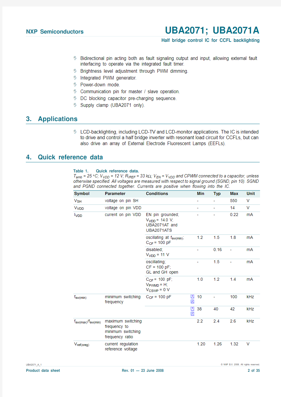
Table 1.Quick reference data.
T amb=25°C;V VDD=12V;R IREF=33k?;V EN=V VDD and CPWM connected to a capacitor,unless
otherwise speci?ed.All voltages are measured with respect to signal ground(SGND,pin10).SGND
and PGND connected together. Currents are positive when ?owing into the IC.
Symbol Parameter Conditions Min Typ Max Unit
V SH voltage on pin SH--550V
V VDD voltage on pin VDD--14V
I VDD current on pin VDD EN pin grounded;
V VDD= 14.0 V;
UBA2071A T and
UBA2071A TS
--0.22mA
oscillating at f sw(min);
C CF=100pF
1.2 1.5 1.8mA
disabled;
V VDD=11V
-0.16-mA
oscillating;
CF=100pF;
GL and GH open
- 1.5-mA
C CF= 100 pF;
V PWMD=H;
V CSWP=0V
1.0 1.2 1.4mA
f sw(min)minimum switching
frequency C CF=100pF[1]
[2]
10-100kHz
[1]
[2]
384042kHz
f sw(max)/f sw(min)maximum switching
frequency to
minimum switching
frequency ratio
2.2 2.4 2.6kHz
V ref(creg)current regulation
reference voltage
1.20 1.26 1.32V
[1]Given frequency is switching frequency of GL and GH. Sawtooth frequency on CF pin is twice as high.[2]Can be set by external capacitor
[3]
PWMD is active low: A low level on the PWMD pin corresponds with lamps-on. Example:δPWM = 20 %means PWMD is during 20 % of each cycle low and the lamps are 20 % of the time on, resulting in a light output of 20 %.
5.Ordering information
V th(ov)(VFB)
overvoltage
threshold voltage on pin VFB
2.40
2.50
2.60
V
t to(fault)fault time-out time C CT = 100 nF 0.85 1.00 1.15s I source(drv)driver source current V GL , V GH = 4 V;V VDD =V FS =12V ?105?90?75mA R sink(drv)driver sink resistance V GL , V GH = 2 V;V VDD =V FS =12V
13.516.018.5?f PWM PWM frequency [1]75-1000Hz δPWMD
duty cycle on pin PWMD
[3]
12
-
100
%
Table 1.Quick reference data.
T amb =25°C;V VDD =12V;R IREF =33k ?;V EN =V VDD and CPWM connected to a capacitor,unless otherwise speci?ed.All voltages are measured with respect to signal ground (SGND,pin 10).SGND and PGND connected together. Currents are positive when ?owing into the IC.Symbol Parameter Conditions Min Typ Max Unit Table 2.
Ordering information
Type number
Package Name
Description
Version UBA2071T SO24plastic small outline package; 24leads; body width 7.5mm SOT137-1UBA2071A T SO24plastic small outline package; 24leads; body width 7.5mm SOT137-1UBA2071TS SSOP24plastic shrink small outline package; 24leads;body width 5.3mm
SOT340-1UBA2071A TS
SSOP24
plastic shrink small outline package; 24leads;body width 5.3mm
SOT340-1
6.Block diagram
Fig 1.Block diagram
ARCING DETECTION
DOUBLE SIDE RECTIFIER
HARD-SWITCHING DETECTION
MASTER / SLAVE COMMUNICATION
NON-OVERLAP
TIMING
PWM GENERATOR
LAMP CURRENT SENSING
OVER-CURRENT DETECTION
OVER-VOLTAGE SENSING TRACK AND SWEEP
INTERNAL SUPPL Y AND
REFERENCE CIRCUITS
LEVEL-SHIFTER
TIMER
HF
OSCILLATOR
CONTROL
IREF VDD EN
CF
CSWP CVFB
VFB
IFB
CIFB PWMA PWMD CPWM
FS
GH
SH
GL
PGND
COMM
VDD
bootstrap diode
VDD
low-side driver
high-side
driver
UBA2071
SGND CT
NONFAULT
014aaa098
7.Pinning information
7.1Pinning
7.2Pin description
Fig 2.Pin assignment SO24 and SSOP24 package (top view)
UBA2071
IFB GH CIFB FS VFB SH CVFB n.c.CSWP
n.c.CT n.c.CF GL IREF PGND CPWM
VDD SGND EN COMM PWMA NONFAULT PWMD
014aaa099
123456789
101112
141316151817201922212423Table 3.Pin description Symbol Pin Description
Function
IFB 1current feedback input.Input signal for the lamp current control loop. Should be connected to a voltage proportional to the lamp current.
CIFB 2current regulation capacitor.
A capacitor must be connected between this pin and the signal ground. It sets the time constant of the lamp current control loop.
VFB 3voltage feedback input Input signal for the voltage control loop. Should be connected to a voltage proportional to the transformer output voltage.
CVFB 4voltage regulation capacitor A capacitor must be connected between this pin and the signal ground. It sets the time constant of the voltage control loop.
CSWP
5
frequency sweep capacitor
A capacitor must be connected between this pin and the signal ground. It sets the time in which the HF frequency is swept up from regulation level to the maximum frequency and back during PWM dimming.
CT 6fault timing capacitor A capacitor must be connected between this pin and the signal ground. It sets the time that a fault condition is allowed before the IC shuts down itself.CF 7HF-oscillator timing capacitor
A capacitor must be connected between this pin and the signal ground. It sets the minimum switching frequency of the half bridge.
IREF 8reference current output A 33 k ? resistor must be connected between this pin and the signal ground.The IC uses it to make accurate internal currents.
CPWM
9
PWM timing capacitor
If a capacitor is connected between this pin and the signal ground,it sets the frequency of the PWM oscillator.
If this pin is connected to signal ground the internal PWM oscillator is disabled.
SGND 10signal ground COMM
11
master / slave communication
Via this pin the IC can communicate with a dedicated slave device.
8.Functional description
The UBA2071 and UBA2071A are designed to drive a half bridge inverter (as shown in Figure 3)with a resonant load.The load consists typically of a transformer with CCFLs or EEFLs.
The IC has an AC lamp current sense input (IFB).It regulates the average absolute value of the lamp current by varying its switching frequency. The load is presumed to be inductive: higher frequency results in lower lamp current.
The UBA2071 and UBA2071A include a PWM dimming function. The ICs switch the lamps on and off with a frequency lower than the lamp current frequency but higher than what the human eye can see. The light output of the lamps can be set by setting the ratio of the on-time and off-time.
These ICs have several forms of protection and the next chapters will describe each function in more detail.
NONFAULT 12status signal input/output
The IC signals a fault condition to external circuits by pulling this pin low.Also external circuits can signal a fault condition to the IC by pulling this pin low.PWMD
13
digital PWM dimming input/output
Digital output of internally generated PWM signal if a capacitor is connected to the CPWM pin.
Digital input of PWM signal if the CPWM pin is connected to signal ground.Remark:The signal on the PWMD pin is active low, so low voltage on the PWMD pin means lamps are on.
PWMA 14analog PWM dimming input
The duty cycle of the internally generated PWM signal is proportional to the voltage on this pin.
EN
15
chip enable input
A low voltage on this pin will reset and shut down the IC.This pin is also used to select between DC blocking capacitor charging mode and normal operation.
VDD 16supply input A buffer capacitor must be connected between this pin and power ground.PGND 17power ground return for the low-side driver.
GL 18low-side driver output Gate connection of the low-side power switch.n.c.19not connected HV spacer pin.n.c.20not connected HV spacer pin.n.c.21not connected HV spacer pin.
SH 22high-side source connection Return for high side gate driver. Must be connected to the source of the high-side half bridge power switch.
FS
23
?oating supply
A buffer capacitor must be connected between this pin and the SH pin. This capacitor is charged when the low-side power switch is on and supplies the high-side driver when the high-side power switch is on.GH 24high-side driver output
Gate connection of the high-side half bridge power switch.
Table 3.Pin description …continued Symbol
Pin
Description Function
8.1Supply, Start-up and UnderVoltage LockOut (UVLO)
The UBA2071 is supplied via the VDD pin as shown in Figure 4. The supply voltage is either made by the inverter itself, using a ?V/?t or is a auxiliary ?xed supply voltage. A start-up current source that can supply minimal I startup(VDD)is needed for start-up.This can be a resistor to the half bridge supply voltage.
The IC starts up when the voltage at the VDD pin goes over V startup(VDD) and shuts down when the voltage at the VDD pin drops below V stop(VDD) and the output GL is high 1. The hysteresis between the start and stop levels allows the IC to be supplied by the supply buffer capacitor (C1 in Figure 4) until the auxiliary supply is settled. The auxiliary supply must not exceed the maximum voltage allowed on the VDD pin and has to be above V stop(VDD).
The UBA2071A can directly be supplied by a ?xed voltage source on the VDD pin. The voltage supplied by this source has to be above the maximum value of V startup(VDD) but below the maximum of V VDD . Typically it will be a 12 V ± 5 % source.
Fig 3.Basic half bridge inverter
LOAD
V HV
0.5 V HV
V HB
GL SH GH
FS VDD
PGND
UBA2071
014aaa100
C FS
Q HS
Q LS
C block
Fig 4.Supply con?guration (for UBA2071 only)
1.
When both GH and GL are low, during the lamps-off period of PWM dimming (PWMD is high), the IC will shut down until the PWMD is low and the GL is high again.
UBA2071
V DD
start up current
AUXILARY SUPPL Y
C1
014aaa101
8.2V DD clamp
When the UBA2071 is disabled (EN pin low) or in the stop state, the V DD clamp is
activated. The V DD clamp is an internal active zener limiting the voltage to V clamp(VDD). It
prevents the start-up current source from charging the V DD buffer capacitor to too high a
voltage.
The maximum current that is allowed to be delivered by the start-up current source is
determined by the clamp voltage as stated in Table6 and the maximum allowed V DD
voltage as stated in T able4.
The UBA2071A has no V DD clamp.
8.3Enable
The UBA2071 or UBA2071A can be activated or set to standby via the EN pin. If the
voltage on the EN pin is below V th(L)(EN), the IC will stop oscillating at the next GL high
state2,and most parts of the internal circuits will shut down.When the EN pin is left open,
it is pulled low by an internal bias current of I bias(EN).
When the voltage on the EN pin comes above V th(H)1(EN), the IC will start up in
DC blocking capacitor charging mode (see Section8.8). When the voltage on the EN pin
goes over V th(H)2(EN), the IC will start with the initial ignition frequency sweep (see
Section8.8) and subsequently go to normal operation mode again.
8.4The oscillator
The UBA2071and UBA2071A have an internal voltage controlled sawtooth oscillator,see
Figure5. Its frequency inverses in proportion to the capacitor connected to the CF pin.
The IC switches GL on and GH off during one oscillator period and GL off and GH on
during the next oscillator period. This results in a half bridge voltage with a frequency
(called the switching frequency f sw from here on)of half the oscillator frequency and with a
duty cycle of exactly 50 %.
The oscillator frequency is controlled by changing the charge current at the CF pin. By
changing the frequency the lamp current is controlled. It is also used to limit the
transformer output voltage and for gradually switching the lamps on and off during PWM
dimming.
2.When both GH and GL are low during the lamps off period of PWM dimming (so PWMD is high), the IC will wait with entering the
standby state until PWMD becomes low again and GL can be made high.
8.5Non-overlap
During each transition between the two states GL high/GH low and GL low/GH high, GL and GH will both be low for a ?xed time t no (non-overlap time)to allow the half bridge point to be charged or discharged by the load current (presuming the load always has an inductive behavior), and thus enabling zero voltage switching, see Figure 5.
8.6Low-side and high-side drivers
The low-side and high-side drivers are identical.The output of each driver is connected to the equivalent gate of an external power MOSFET.The high-side driver is supplied by the bootstrap capacitor,which is charged from the V DD voltage via an internal diode when the low-side power MOSFETs is on. The low-side driver is directly supplied by the V DD voltage.
8.7DC blocking capacitor charging
When the IC is off, either because V VDD is too low, it is disabled via the EN pin, or it stopped after the time-out period during a fault condition, the low-side power switch (Q LS in Figure 3) is turned on by making GL high. This ensures that the supply buffer capacitor of the ?oating supply (C FS in Figure 3) is fully charged at start-up. As a side effect the DC blocking capacitor (C block in Figure 3) will be completely discharged at start-up. T o prevent large inrush currents during the ?rst switching cycles the UBA2071and UBA2071A can ?rst charge the DC blocking capacitor at start-up.
Fig 5.Oscillator, driver and half bridge voltages
t
V CF
V CFH 0t
V GH ? V SH
V DD
0t
V GL
V DD 0t
V HB
V HV 0
t no
014aaa102
When the voltage on the EN pin goes over V th(H)1(EN) after the IC has been disabled (EN pin below V th(L)(EN)) the IC will start up in DC blocking capacitor charging mode 3. When the voltage on the EN pin goes over V th(H)1(EN) after the IC has been off (EN pin below V th(L)(EN) or V DD below V stop(VDD)) the IC will start up in DC blocking capacitor charging mode. When the voltage on the EN pin goes over V th(H)2(EN) the IC will continue with the initial ignition frequency sweep and normal operation mode.Figure 6, EN con?guration,shows three examples of how the enable input can be used:
1.Digital enable input with DC blocking capacitor charging. R1 and C1 de?ne a ?xed DC blocking capacitor charging time.Remark:The digital input signal high level has to be above the maximum value of V th(H)2(EN).
2.Sensing of HV supply and DC blocking capacitor voltages via the EN pin. The IC will start in DC blocking capacitor charging mode if V VDD is above V startup(VDD)and V HV is above .It will then go into initial ignition frequency sweep and normal operation mode once V Cblock has been charged to .
3.Sensing of HV supply and DC blocking capacitor voltages via the EN pin combined with digital enable input.In DC blocking capacitor charging mode the low-side power switch (Q LS in Figure 3) is turned on for a period ((1/f sw(max))? t no ) and then the high-side power switch (Q HS in Figure 3) is turned on for a period ((1/f sw(max))? t no ) followed by a period of (3/f sw(min))during which both power switches are off. This is repeated until the mode is left. When leaving the DC blocking capacitor charging mode by raising the EN pin above V th(H)2(EN),the running cycle of the DC blocking capacitor charging mode will ?rst be completed (see Figure 7).
3.
When the enable input is kept high during the time that the IC is off,because the supply voltage is too low,the IC might not start in DC blocking capacitor charging mode.
Fig 6.EN con?guration
014aaa253
UBA2071
EN
C1
R1
enable
(1)
UBA2071
EN
R 4V Cblock
V Hv
(2)R 3
R 2
C block
UBA2071
EN
R 4V Cblock
V Hv
(3)
R 3
R 2
C block
R 5
disable
R2/R4()R2/R3()1++()V th(H)1(EN)×R4/R2()R4/R3()1++()V th(H)2(EN)R4/R2V HV ×–×()
Remark:Due to the nature of the charging sequence, V Cblock will automatically be
charged to 0.5× V HV (when given enough time). If the IC is kept in DC blocking capacitor charging mode longer than necessary, V Cblock will remain 0.5× V HV . Therefor the time constant made by R1 and C1 in example A in Figure 6, is not critical. However, since V Cblock cannot become more than 0.5×V HV ,it is important to take a lower target value for V Cblock than 0.5× V HV (with enough margin) in examples B and C of Figure 6, otherwise the IC may get stuck in DC blocking capacitor charging mode.
8.8Lamp (re-)ignition
The IC starts at its maximum switching frequency f sw(max).The lamp current and the lamp voltage control loops are enabled. The frequency is swept down towards the minimum frequency f sw(min), see Figure 9. During this initial ignition frequency sweep the lamp voltage will increase as the frequency comes closer to the resonant frequency of the
unloaded resonance circuit.Once the ignition voltage V ign is reached the lamps will ignite and the lamp voltage will drop 4 to the voltage of the loaded resonance curve, see Figure 8.
Fig 7.DC blocking capacitor charging mode
014aaa252
V SH
(L)(EN)
(H)1(EN)(H)2(EN)EN
GH
GL
disabled
DC blocking capacitor charging
initial ignition sweep and normal mode
0.5 T T 7.5 T 7.5 T 3 / f sw(min)
3 / f sw(min)
1 / f sw(max)
4.For CCFLs only.
V lamp
(V)
(1)
V ign
(2)
V burn
f sw(min)f re
g f ign f sw(max)
f (kHz)
014aaa103
(1)Indicates lamp-OFF.
(2)Indicates lamp-ON.
Fig 8.Initial ignition of cold cathode ?uorescent lamp via frequency sweep and load resonance
Advantage of the sweep rather than a?xed ignition frequency is that sensitivity for spread in resonance frequency is much lower.
Once the lamps are ignited the frequency sweep-down continues,gradually increasing the lamp current (the resonance circuit should now still be inductive, so current increases as frequency drops) until the current regulation level is reached (at f sw = f reg). The frequency will not reach f sw(min)if the lamp current comes into regulation.Once it has been detected that the lamps are on (if the average absolute voltage at the current feedback input (pin IFB) is above V th(lod)(IFB)) PWM dimming is enabled. See Figure9.
The initial ignition frequency sweep and the PWM generator are not synchronized. Once the regulation frequency is reached, PWM dimming can start anywhere in its cycle. A small internal PWM dimming enable delay time, t d(en)PWM, allows the lamps to settle before PWM dimming starts.
At the start of the lamps-off period of the PWM dimming,the switching frequency is swept up to f sw(max). This reduces the lamp voltage so the lamps go out. If f sw(max) is reached, both GL and GH are made low,so both half bridge powers will be non-conducting.This is indicated by the dotted part of the switching frequency (f sw) line in Figure9.
The lamps start switching again on period GL and GH and the frequency is swept back to the regulation frequency f reg . The duration of the PWM frequency sweep is inverse proportional to the capacitor connected to the CSWP pin.
8.9Overvoltage control
The overvoltage control circuit is intended to prevent the transformer output voltage from exceeding its maximum rating. It can also be used to regulate the output voltage to the required lamp ignition voltage.
Under normal circumstances the capacitor at the CVFB pin is charged by a constant bias current I ch(CVFB),thus the voltage on the CVFB pin will increase resulting in a decrease of switching frequency. If the IC is in current regulation this bias current will ?ow away via a tracking circuit which makes the voltage on the CVFB pin following the voltage on the CIFB pin, see Figure 11.
Fig 9.Initial ignition frequency sweep and PWM dimming frequency sweep signals
t
f sw
min max ignition
f re
g f ign 0t
V sec
ov
t
V CVFB V CIFB V CSWP
max
t
V PWMD
t
I lamp
nom PWM-enable delay 014aaa104
steady-state
initial ignition sweep
V CVFB
V CIFB
V CSWP
When the voltage on the VFB pin exceeds V th(ov)(VFB), a fault condition is signalled (for handling of fault conditions, see Section 8.14) and the bias current at the CVFB pin
changed to the discharge current I dch(CVFB).As a result,the switching frequency increases and the output voltage of the transformer will decrease 5. As soon as the voltage at the VFB pin drops below V th(ov)(VFB), the CVFB capacitor is charged again and the output voltage of the transformer will increase again. Because the charging and discharging of the CVFB capacitor follows the ripple on the VFB pin voltage, the feedback gain of the voltage control loop is set by the ripple on the feedback signal.
The voltage at the CVFB pin is limited by the oscillator circuit to V CVFB(max) when the minimum switching frequency f sw(min) is reached, see Figure 10. This ensures an immediate frequency increase when overvoltage is detected.
8.10Lamp current control
The lamp current control is always active when the IC is on, except if the lamps are off during PWM dimming. The AC lamp current is sensed by an external resistor connected to the IFB pin, see Figure 11. The resulting AC voltage on the IFB pin is internally Double-Sided Recti?ed (DSR) and compared to a reference level V ref(creg) by an Operational T ransconductance Ampli?er (OTA).
When the current is being regulated,switch S1is closed (conducting).The output current of the OT A is fed into capacitor C1,which is connected to the CIFB pin.So C1is charged and discharged according to the voltage on the IFB pin.
5.Presuming that the load impedance is in inductive region.
Fig 10.Frequency function of CVFB voltage
Voltage on CVFB-pin
frequency
f sw(min)
f sw(max)
V CVFB(max)
014aaa105
Under normal operating conditions, the voltage across capacitor C2, which is connected to the CVFB pin,will follow the voltage on the CIFB pin.During the lamps-on period of the PWM dimming,the voltage across C3,which is connected to the CSWP pin,will follow the voltage on the CVFB pin and therefore also the voltage on the CIFB pin.
The voltage on the CSWP pin is connected to the VCO input of the HF oscillator and thus controls the switching frequency.If the load is assumed to be inductive an increase in the frequency will cause a decrease in the lamp current,while a decrease in the frequency will cause an increase in the lamp current.
The advantage of having a separate current regulation loop timing capacitor pin CIFB next to the voltage regulation loop timing capacitor CVFB is that time constants for both loops can be set independently.The separate PWM dimming sweep timing capacitor pin CSWP makes it possible to set the PWM dimming sweep speed independent of the current and voltage regulation loops.
8.11PWM dimming
Pulse Width Modulation (PWM) dimming is a method of reducing the average lamp light output by switching the lamps on and off with a repetition rate or PWM frequency, f PWM ,high enough not to be seen by the human eye (but much lower than the inverter frequency f sw ). By varying the lamp-on to lamp-off, period ratio, called the duty cycle δPWM , the light output can be varied over a wide range.
The voltage at the CSWP pin determines the actual switching frequency, it inverses in proportion to the switching frequency.During the lamps-on period of the PWM dimming it follows the voltage at the CVFB pin (the current I ch(CSWP) is drained by the tracking circuit between the CVFB pin and the CSWP pin).
Just prior to transitioning towards the lamps-off period of the PWM dimming the lamp current control loop,see Figure 11,is opened by opening switches S1.The voltage on the CSWP pin is swept down, decaying the lamp current, leading in the PWM lamp-off
situation,after which the half bridge switch actions are stopped,resulting in true zero lamp current.see Figure 9.In the meantime the regulation level is preserved in C1and C2.The
Fig https://www.doczj.com/doc/9310165067.html,mp frequency control circuit
R1
C1
to CCFLs
DSR
V ref(creg)
C2
C3
I ch(CSWP)PWMD
01
I dch(CSWP)
S2
S1
to VCO
I ch(CVFB)
CIFB
CVFB
CSWP
UBA2071
OT A
014aaa106
IFB
PWM lamp-on situation is reached again through a reverse sequence of events, starting the half bridge actions,increasing the voltage on CSWP ,increasing the lamp current back to the controlled value. Switch S1 is closed (conducting) again when the voltage on the CSWP pin has reached the voltage on the CVFB pin again.
The IC waits until the CSWP sweep-up 6 has reached the current/voltage control level at the CVFB pin before sweeping down. This prevents the lamps from going out completely when deep dimming on CSWP pin is combined with a large value capacitor.
After the switching frequency has reached f sw(max),both GL and GH are made low,so both half bridge powers will be non-conducting, see Figure 12. This guarantees zero lamp current during the PWM-off period 7, while the CSWP frequency sweep acts as soft stop and soft restart, of which the softness can be set by the value of the capacitor connected to the CSWP pin.
Three pins are available to con?gure the internal PWM generator:the CPWM pin,PWMA pin,and the PWMD pin.The two possible PWM con?gurations are shown in Figure 13.In the analog or master mode the internal PWM generator is active and generating the PWM signal. This signal is put on the PWMD pin, which is automatically con?gured as an output. The minimum duty cycle of the internal PWM generator is limited to δPWM(min).
6.CSWP sweep-up is frequency sweep-down.
7.
Until the ringing of voltage on the half bridge point has died away, some (capacitive) current may still cause a light glow at the hot side of the lamps.Therefore it is advised to maximize the attenuation of the ringing circuit (made up by the transformer inductance and the ?V/?t limiting capacitor).
Fig 12.PWM dim cycle waveforms
t
V CSWP
max reg
5 V
V DD
V DD 0
t
V PWMD
t
V GH ? V SH
t
V GL
014aaa107
When the CPWM pin is connected to ground the IC is put in digital or slave mode and the PWMD pin is an input. The internal PWM generator is not used. The IC uses the PWM signal provided on the PWMD pin.
PWM dimming of multiple ICs can be synchronized by con?guring one IC as master and the others as slaves and connecting all PWMD pins together.
The PWMD input/output is active low. A voltage below V th(L)(PWMD) on the pin will turn the lamps on, while a voltage above V th(H)(PWMD) will turn the lamps off.
PWM dimming is only enabled in normal mode, when no fault condition exists. The only exception is when an external detected fault condition is entered via the NONFAULT pin,then PWM dimming remains active, see Figure 15.
8.12The fault timer
The fault timer provides a delay in between the detection of a fault and the shutdown of the IC (enter STOP state). Its time is controlled by a capacitor at the CT pin.
Any fault condition will start the timer. When the timer is activated, the capacitor at the CT pin will be alternatively charged and discharged, see Figure 14. After the fault output delay time, t d(o)fault), the NONFAULT pin is activated (pulled low). This is to signal to any external circuit that a fault has been detected and the IC will stop if that fault continues.After the fault time-out period t to(fault) is reached the IC will enter STOP state.
Fig 13.PWM dimming con?gurations
C1
R PWMA
PWMA analog in
PWM out
CPWM
9PWMD V PWMA(ref)
14
13
PWM intern
UBA2071
A: analog or master mode
PWM in UBA2071
B: digital or slave mode
PWM intern
014aaa108
PWMA CPWM 9
PWMD 14
13
If the fault timer is inactive, the CT pin voltage is 1 Vbe, about 0.7 V . The CT timer has a protection that prevents the IC to start up if the CT pin is shorted to GND.
8.13Communication
The UBA2071 and UBA2071A have a dedicated communication pin, the COMM pin, for communicating with a slave half bridge driver (like the UBA2073),for instance for use in a balanced half bridge driver con?guration.
Via the COMM pin,a clock signal and a signal to indicate that both half bridge powers are to be turned off are exported and a fault signal is imported. The clock signal is a digital signal with a low level V L(clk)(COMM) and a high level V H(clk)(COMM). To signal that both half bridge powers should be turned off, the voltage at the COMM pin is raised to V O(hbswoff)(COMM).
The UBA2071 and UBA2071A look at the current drawn from the COMM pin during the clock high period for a hard switching signal from the slave half bridge driver. First, a non-overlap time period t no is discarded to prevent that a capacitive load on the
communication line is seen as a signal. Then the detected current is averaged over the clock high period before being compared to the reference level I th(det)hsw(COMM). The
current value is sampled on the falling edge of the clock signal and held during the clock low period.The received signal is treated as equal to an internal hard switching detection (so PWM dimming will be disabled, switching frequency will be increased and fault timer will be started).
When only the UBA2071 or UBA2071A is used, the COMM pin must be “not connected”.
8.14Protections
All fault conditions and how they are processed in the IC can be found in Figure 15.The UBA2071 and UBA2071A have the following protections:
?OverVoltage Protection (OVP),
?OverVoltage Extra protection (OVE),
Fig 14.Fault timer waveforms
t
V CT
t V NONFAULT
IC in STOP-state
t d(o)fault
014aaa110
t to(fault)
?OverCurrent Protection (OCP),?bad contact or ARCing (ARC),?Ignition Failure (IF),
?open or shorted current feedback (IFB pin open/short),?open or shorted voltage feedback (VFB pin open/short)?
Hard Switching (HS).
There are also two pins, the NONFAULT pin and the COMM pin, via which a fault can be signalled to the IC, by an external circuit.
The fault protection functions are explained in the following sections.
8.14.1Voltage feedback open or short protection
If the VFB pin is left open or shorted to SGND, the voltage at the VFB pin will drop below the VFB open/short protection threshold voltage V th(osp)VFB , due to the internal bias resistor R i(VFB). If the voltage at the VFB pin is below V th(osp)VFB continuously or only during a part of each switching cycle the PWM dimming is disabled and the fault timer is started.
To protect the inverter transformer(s) against overvoltage if the voltage feedback loop is broken, the frequency stays at f sw(max) or is increased by discharging the capacitor at the CVFB pin (by I dch(CVFB)). For this function the voltage at the VFB pin has to be below V th(osp)VFB during more than 50 % of each switching cycle.
Fig 15.Simpli?ed control schematic
enable low_supply
NONFAULT -pin_fault_signal
IFB_open /short
over_voltage_extra over_voltage VFB_open /short
COMM-pin_fault_signal hard_switching_detected
over_current
f_max
arcing_detected
lamp_current_detected
f_min
ic_off
FAULT -TIMER
FILTER
stop
R S Q
lamp_on
ignition_failure
R S Q
DELAY
enable_PWM_dimming
014aaa111
8.14.2Overvoltage protection
The overvoltage control, see Section8.9, is intended to prevent the transformer output
voltage from exceeding its maximum rating. The overvoltage control level has to be at
least at the required lamp ignition voltage, otherwise the lamps may not ignite.
Once the lamps are on and in steady state, the transformer output voltage will usually be about half the required ignition voltage for CCFLs. Thermal design of the transformers is
based on this lower voltage, not on the ignition voltage above which the overvoltage
control has to be. Hence the circuit might not stay in overvoltage regulation inde?nitely.
Therefore overvoltage regulation is combined with overvoltage protection.
When the voltage on the VFB pin exceeds the OV reference level V th(ov)(VFB),the CVFB is discharged,an overvoltage fault condition is signalled,PWM dimming is disabled,and the fault timer is started.An internal latch makes the OV fault signal continuously high,even if the voltage at the VFB pin only exceeds V th(ov)(VFB)during part of the output period.So the peak of the voltage on the VFB pin determines if an overvoltage fault condition is seen.An internal?lter prevents the overvoltage fault condition from being reset when the voltage at the VFB pin drops below the OV reference level for only one or two hf cycles.
In order to avoid an OV fault condition at the nominal switching frequency(with the lamps operating normally), the voltage ripple on the VFB pin must not be too large.
8.14.3Hard switching protection
As the UBA2071 and UBA2071A are intended to drive a half bridge at a high voltage, a
feature is included to ensure zero voltage switching. The design of the resonant load
should guarantee zero voltage switching under normal operating conditions. To prevent
overheating due to high switching losses in case of any abnormal operating condition,
hard switching of the half bridge is detected internally.
At the moment the high-side switch is turned on, the voltage step at the SH pin is
measured. If it is above V th(hsw)(SH) then PWM dimming is disabled and the fault timer is
started.Also,the frequency is increased by discharging the capacitor at the CVFB pin(by
I dch(CVFB)).
8.14.4Overvoltage extra protection
Though the hard switching protection as described in Section8.14.3,usually prevents the circuit from getting at the wrong side of the resonance curve of the load (were the load
shows capacitive behavior), this might happen for instance when a lamp is suddenly
disconnected.The parasitic capacitance of the lamp and its connection wire may make up
a signi?cant part of the resonance circuit capacitance, so if a lamp is disconnected the
resonance frequency of the remaining load is suddenly higher and the switching
frequency might be at the capacitive side.Hard switching will occur and be detected.The result is an increase in the switching frequency, which will make the situation worse: the
switching frequency comes closer to the resonance frequency of the remaining load,
creating a higher and potentially destructive transformer secondary voltage.
The OverVoltage Extra (OVE), protection prevents damage to the circuit by adding an
extra overvoltage protection level with quick response to that. When the voltage on the
VFB pin exceeds this OVE level V th(ovextra)(VFB),an OVE fault condition is signalled.The IC will stop if this happens during a couple of subsequent hf cycles. The time it takes before the IC stops depends on a percentage of the time the VFB pin voltage exceeds the OVE
level and if hard switching is detected also.Figure16 shows typical shutdown response
因此各位朋友在选择LCD液晶模块的时候,在考虑到串行,还是并行的方式时,可根据其驱动控制IC的型号来判别,当然你还需要看你选择的LCD模块引脚定义是固定支持并行,还是可选择并行或串行的方式。 一、字符型LCD驱动控制IC 市场上通用的8×1、8×2、16×1、16×2、16×4、20×2、20×4、40×4等字符型LCD,基本上都采用的KS0066作为LCD的驱动控制器 二、图形点阵型LCD驱动控制IC 1、点阵数122×32--SED1520 2、点阵数128×64 (1)ST7920/ST7921,支持串行或并行数据操作方式,内置中文汉字库 (2)KS0108,只支持并行数据操作方式,这个也是最通用的12864点阵液晶的驱动控制IC (3)ST7565P,支持串行或并行数据操作方式 (4)S6B0724,支持串行或并行数据操作方式 (5)T6963C,只支持并行数据操作方式 3、其他点阵数如192×6 4、240×64、320×64、240×128的一般都是采用T6963c驱动控制芯片 4、点阵数320×240,通用的采用RA8835驱动控制IC 这里列举的只是一些常用的,当然还有其他LCD驱动控制IC,在写LCD驱动时要清楚是哪个型号的IC,再到网上去寻找对应的IC数据手册吧。后面我将慢慢补上其它一些常见的. 三 12864液晶的奥秘 CD1601/1602和LCD12864都是通常使用的液晶,有人以为12864是一个统一的编号,主要是12864的液晶驱动都是一样的,其实12864只是表示液晶的点阵是128*64点阵,而实际的12864有带字库的,也有不带字库的;有5V电压的,也有~5V(内置升压电路);归根到底的区别在于驱动控制芯片,常用的控制芯片有ST7920、KS0108、T6963C等等。 下面介绍比较常用的四种 (1)ST7920类这种控制器带中文字库,为用户免除了编制字库的麻烦,该控制器的液晶还支持画图方式。该类液晶支持68时序8位和4位并口以及串口。 (2)KS0108类这种控制器指令简单,不带字库。支持68时序8位并口。 (3)T6963C类这种控制器功能强大,带西文字库。有文本和图形两种显示方式。有文本和图形两个图层,并且支持两个图层的叠加显示。支持80时序8位并口。 (4)COG类常见的控制器有S6B0724和ST7565,这两个控制器指令兼容。支持68时序8位并口,80时序8位并口和串口。COG类液晶的特点是结构轻便,成本低。 各种控制器的接口定义: 引脚定义
对“剖析液晶屏逻辑板TFT偏压电路”一文的一点看法(此文为技术探讨) 在国内某知名刊物2010年12月份期刊看到一篇关于介绍液晶屏逻辑板TFT偏压电路的文章,文章的标题是:“剖析液晶屏逻辑板TFT偏压电路”这是一篇选题极好的文章、目前液晶电视出现的极大部分屏幕故障例如:图像花屏、彩色失真、灰度失真、对比度不良、亮度暗淡、图像灰暗等等故障都与此电路有关,维修人员在维修此类故障时往往的面对液晶屏图像束手无策,而介绍此电路、无疑对类似故障的分析提供了极大的帮助,目前在一般的期刊书籍介绍分析此电路的文章极少。 什么是TFT屏偏压电路?现代的液晶电视都是采用TFT屏作为图像终端显示屏,由于我们现在的电视信号(包括各种视频信号)是专门为CRT显示而设计的,液晶屏和CRT的显示成像方式完全不同,液晶屏要显示专门为CRT而设计的电视信号,就必须对信号的结构、像素排列顺序、时间关系进行转换,以便液晶屏能正确显示。 图像信号的转换,这是一个极其复杂、精确的过程;先对信号进行存储,然后根据信号的标准及液晶屏的各项参数进行分析计算,根据计算的结果在按规定从存储器中读取预存的像素信号,并按照计算的要求重新组合排列读取的像素信号,成为液晶屏显示适应的信号。这个过程把信号的时间过程、排列顺序都进行了重新的编排,并且要产生控制各个电路工作的辅助信号。重新编
排的像素信号在辅助信号的协调下,施加于液晶屏正确的重现图像。 每一个液晶屏都必须有一个这样的转换电路,这个电路就是我们常说的“时序控制电路”或“T-CON(提康)电路”,也有称为“逻辑板电路”的。这个电路包括液晶屏周边的“行、列驱动电路”构成了一个液晶屏的驱动系统。也是一个独立的整体。这个独立的整体是由时序电路、存储电路、移位寄存器、锁存电路、D/A变换电路、译码电路、伽马(Gamma)电路(灰阶电压)等组成,这些电路的正常工作也需要各种不同的工作电压,并且还要有一定的上电时序关系,不同的屏,不同的供电电压。为了保证此电路正常工作,一般对这个独立的驱动系统单独的设计了一个独立的开关电源供电(这个向液晶屏驱动系统供电的开关电源一般就称为:TFT偏压电路);由整机的主开关电源提供一个5V或12V 电压,给这个开关电源供电,并由CPU控制这个开关电源工作;产生这个独立的驱动系统电路提供所需的各种电压,就好像我们的电视机是一个独立的系统他有一个单独的开关电源,DVD机是一个独立的系统他也有一个单独的开关电源一样。是非常重要也是故障率极高的部分(开关电源都是故障率最高的部分,要重点考虑)。图1所示是液晶屏驱动系统框图。从图中可以看出,其中的“TFT偏压供电开关电源”就是这个独立系统电路的供电电源它产生这个驱动系统电路需要的各种电压,有VDD、VDA、VGL和VGH电压供各电路用。
LED 常用芯片技术资料 1、列电子开关74HC595 (串并移位寄存器) 第14脚DATA ,串行数据输入口,显示数据由此进入,必须有时钟信号的配合才能移入。 第13脚EN ,使能口,当该引脚上为“1”时QA~QH口全部为“1”,为“0”时QA~QH的输出由输入的数据控制。第12脚STB ,锁存口,当输入的数据在传入寄存器后,只有供给一个锁存信号才能 将移入的数据送QA~QH口输出。 第11脚CLK ,时钟口,每一个时钟信号将移入一位数据到寄存器。 第10脚SCLR ,复位口,只要有复位信号,寄存器内移入的数据将清空,一般接VCC 。第9脚DOUT ,串行数据输出端,将数据传到下一个。第15、1~7脚,并行输出口也就是驱动输出口,驱动LED 。 2、译码器 74HC138 第1~3脚A 、B 、C ,二进制输入脚。第4~6脚片选信号控制,只有在4、5脚为“0”6脚为“1”时,才会被选通,输出受A 、B 、C 信号控制。其它任何组合方式将不被选通,且Y0~Y7输出全为“1”。
3、缓冲器件74HC245 第1脚DIR ,输入输出端口转换用,DIR=“1” A输入B 输出,DIR=“0” B输入A 输出。第2~9脚“A ”信号输入输出端;第11~18脚“B ”信号输入输出端。 第19脚G ,使能端,为“1”A/B端的信号将不导通,为“0”时A/B端才被启用。
4、4953的作用:行驱动管,功率管。 1、3脚VCC , 2、4脚控制脚,2脚控制7、8脚的输出,4脚控制5、6脚的输出,只有当2、4脚为“0”时,7、8、5、6才会输出,否则输出为高阻状态。 5、74HC04的作用:6位反相器。 信号由A 端输入Y 端反相输出,A1与Y1为一组,其它类推。例:A1=“1”则Y1=“0”、A1=“0”则Y1=“1”,其它组功能一样。 6、 74HC126(四总线缓冲器)正逻辑 Y=A 2、SDI 串行数据输入端 3、CLK 时钟信号输入端, 4、LE 数据锁存控制端 5~20、恒流源输出端 21、OE 输出使能控制端 22、SDO 串行数据输出端,级联下一个芯片 23、R-EXT 外接电阻,控制恒流源输出端电流大小
数字芯片的驱动能力详解 1.芯片驱动能力基本概念 芯片驱动能力,是指在额定电平下的最大输出电流;或者是在额定输出电流下的最大输出电压。具体解释如下。 当逻辑门输出端是低电平时,灌入逻辑门的电流称为灌电流,灌电流越大,输出端的低电平就越高。由三极管输出特性曲线也可以看出,灌电流越大,饱和压降越大,低电平越大。然而,逻辑门的低电平是有一定限制的,它有一个最大值UOLMAX。在逻辑门工作时,不允许超过这个数值,TTL逻辑门的规范规定UOLMAX ≤0.4。所以,灌电流有一个上限。 当逻辑门输出端是高电平时,逻辑门输出端的电流是从逻辑门中流出,这个电流称为拉电流。拉电流越大,输出端的高电平就越低。这是因为输出级三极管是有内阻的,内阻上的电压降会使输出电压下降。拉电流越大,输出端的高电平越低。然而,逻辑门的高电平是有一定限制的,它有一个最小值UOHMIN。在逻辑门工作时,不允许超过这个数值,TTL逻辑门的规范规定UOHMIN ≥2.4V。所以,拉电流也有一个上限。 可见,输出端的拉电流和灌电流都有一个上限,否则高电平输出时,拉电流会使输出电平低于UOHMIN;低电平输出时,灌电流会使输出电平高于UOLMAX。所以,拉电流与灌电流反映了输出驱动能力。(芯片的拉、灌电流参数值越大,意味着该芯片可以接更多的负载,因为,例如灌电流是负载给的,负载越多,被灌入的电流越大)。 2.怎么通过数字芯片的datasheet看其驱动能力 以时钟buffer FCT3807例,下图是从Pericom的FCT3807的datasheet截取的。 当其输出为高电平2.4V时,其输出电流为8mA,也就是拉电流为8mA。如果输出电流大于8mA,那么其输出电平就低于2.4V了,就不能称其输出高电平,所以可以说FCT3807输出高电平的驱动能力为8mA。 同样道理,FCT3807输出低电平的驱动能力为24mA。 3.怎么通过数字芯片的驱动能力来估算输出信号的过冲等指标 仍然以Pericom的FCT3807为例,其输出为高电平时的输出阻抗为: RH= (3.3V – 3V )/ 8mA = 37.5欧姆。 其输出为低电平时的输出阻抗为: RL= 0.3V / 24mA = 12.5欧姆。 从上面的计算可以看出,3807输出为高电平和输出为低电平时的驱动能力不一样,也就是输出阻抗不一样,所以用串联匹配的方法很难做到完全匹配,常常表现为overshoot-大
液晶屏背光板工作原理电路图 一、前言随着液晶电视机销量的逐渐增多,需要投入更多的精力来研究液晶电视机的维修,而目前液晶电视机中背光板的维修量占有较大的比例,同时由于背光板是显示屏供应商供屏时自带的,供应商出于对技术的保密性,现在我们还拿不到背光板的电路图和IC资料,这对我们背光板的维修带来了很大的难处。为了改善我们的背光板修理,本文对背光板的通用工作原理及常见故障判断作一介绍,对网络维修具有一定的参考价值。本文的目的是想帮助网络提高维修技能,但由于我们对背光板的电路和维修了解得还不多,因此其中的一些观点可能有不准确或描述错误的地方,请大家指出来共同讨论,从而共同提高我们的维修水平,谢谢!二、背光板在液晶电视机中的作用背光板也称Inverter板即逆变器板,它的作用是将一个直流电压转变为多个交流电压,作为液晶屏灯管的工作电压,它的输入、输出连接框图如下图。背光板有三个输入信号,分别是供电电压、开机使能信号、亮度控制信号,其中供电电压由电源板提供,一般为直流24V(个别小屏幕为12V);开机使能信号ENA即开机控制电平由数字板提供,高电平3V时背光板工作,低电平0V 时背光板不工作;亮度控制信号DIM由数字板提供,它是一个0-3V的模拟直流电压,改变这它可以改变背光板输出交流电压的高低,从而改变灯管亮度。背光板有多个交流输出电压,一般为AC800V,每个交流电压供给一个灯 管。三、背光板工作原理方框图背光板电路由输入接口电路、PWM控制电路、MOS管导通与直流变换电路、LC振荡及高压输出回路、取样反馈电路等几部分组成,其工作原理 方框图:四、背光板各部分电路介绍1、输入接口电路1)供电输入电压输入接口电路中的供电输入电压一路直接加到MOS管导通电路,作
TFT LCD显示原理详解 <什么是液晶> 我们一般认为物体有三态:固态、液态、气态,其实这只是针对水而言,有一些有机化和物还有介于固态和液态中间的状态就是液晶态,如下图(一): 图(一)
图(七) b-1:当在不加上电极的时候,当入射的光线经过下面的偏光板(起偏器)时, 会剩下单方向的光波,通过液晶分子时, 由于液晶分子总共旋转了90度, 所以当光波到达上层偏光板时, 光波的极化方向恰好转了90度。下层的偏光板与上层偏光板, 角度也是恰好差异90度。所以光线便可以顺利的通过,如果光打在红色的滤光片上就显示为红色。效果如图(七)中前两个图所示。 b-2:当在加上电极后(最大电极),液晶分子在受到电场的影响下,都站立着,光路没有改变,光就无法通过上偏光板,也就无法显示,如图(七)蓝色滤光片下面的液晶。 c:TFT-LCD驱动电路。 为了显示任意图形,TFT-LCD用m×n点排列的逐行扫描矩阵显示。在设计驱动电路时,首先要考虑液晶电解会使液晶材料变质,为确保寿命一般都采用交流驱动方式。已经形成的驱动方式有:电压选择方式、斜坡方式、DAC方式和模拟方式等。由于TFT-LCD主要用于笔记本计算机,所以驱动电路大致分成:信号控制电路、电源电路、灰度电压电路、公用电极驱动电路、数据线驱动电路和寻址线驱动电路(栅极驱动IC)。上述驱动电路的主要功能是:信号控制电路将数字信号、控制信号以及时钟信号供给数字IC,并把控制信号和时钟信号供给栅极驱动IC;电源电路将需要的电源电压供给数字IC和栅极驱动IC;灰度电压电路将数字驱动电路产生的10个灰度电压各自供给数据驱动;公用电极驱动电路将公用电压供给相对于象素电极的共享电极;数据线驱动电路将信号控制电路送来的RGB信号的各6个比特显示数据以及时钟信号,定时顺序锁存并续进内部,然后此显示数据以6比特DA变换器转换成模拟信号,再由输出电路变换成阻抗,供给液晶屏的资料线;栅极驱动电路将信号控制电路送来的时钟信号,通过移位寄存器转换动作,将输出电路切换成ON/OFF电压,并顺次加到液晶屏上。最后,将驱动电路装配在TAB(自动焊接柔性线路板)上,用ACF(各向异性导电胶膜)、TCP(驱动电路柔性引带)与液晶显示屏相连接。 d:TFT-LCD工作原理 首先介绍显示原理。液晶显示的原理基于液晶的透光率随其所施电压大小而变化的特性。当光通过上偏振片后,变成线性偏振光,偏振方向与偏振片振动方向一致,与上下玻璃基板上面液晶分子排列顺序一致。当光通过液晶层时,由于受液晶折射,线性偏振光被分解为两束光。又由于这两束光传播速度不同(相位相同),因而当两束光合成后,必然使振光的振动方向发生变化。通过液晶层的光,则被逐渐扭曲。当光达到下偏振片时,其光轴振动方向被扭曲了90度,且与下偏振片的振动方向保持一致。这样,光线通过下偏振片形成亮场。加上电压以后,液晶在电场作用下取向,扭曲消失。这时,通过上偏振片的线性偏振光,在液晶层不再旋转,无法通过下偏振片而形成暗场。可见液晶本身不发光,在外光源的调制下,才能显示,在整个显示过程中,液晶起到一个电压控制的光阀作用。TFT-LCD的工作原理则可简述为:当栅极正向电压大于施加电压时,漏源电极导通,当栅极正向电压等于0或负电压时,漏源电极断开。漏电极与ITO象素电极连结,源电极与源线(列电极)连结,栅极与栅线(行电极)连结。这就是TFT-LCD的简单工作原理
LED电子显示屏常见驱动方式介绍 目前市场上LED显示屏的驱动方式有静态扫描和动态扫描两种,静态扫描又分为静态实像素和静态虚拟,动态扫描也分为动态实像和动态虚拟。下面由明新源科技为大家介绍下LED电子显示屏常见的驱动方式吧。 河南明新源相关负责人介绍说,在一定的显示区域内,同时点亮的行数与整个区域行数的比例,称扫描方式;室内单双色一般为1/16扫描,室内全彩LED显示屏一般是1/8 扫描,室外单双色一般是1/4扫描,室外全彩显示屏一般是静态扫描。驱动IC一般用国产HC595,台湾MBI5026,日本东芝TB62726,一般有1/2 扫,1/4扫,1/8扫,1/16扫。 举列说明:一个常用的全彩模组像素为16*8 (2R1G1B),模组总共使用的LED灯是:16*8(2+1+1)=512个,如果用MBI5026 驱动,MBI5026 为16位芯片,512/16=32 (1)如果用8个MBI5026芯片,是动态1/4扫虚拟。 (2)如果用16个MBI5026芯片,是动态1/2扫虚拟。 (3)如果用32 个MBI5026芯片,是静态虚拟。 (4)用6个MBI5026芯片,是动态1/4扫实像素。 (5)用12个MBI5026芯片,是动态1/2扫实像素。 (6)如果板子上两个红灯串连,用个MBI5026芯片,是静态实像素。 在LED单元板,扫描方式有1/16,1/8,1/4,1/2,静态。LED电子显示屏常见驱动方式介绍还有哪些,该如何区分呢?一个最简单的办法就是数一下单元板的LED灯数目和74HC595的数量。计算方法:LED的数目除以74HC595的数目再除以8 =几分之一扫描。 实像素与虚拟是相对应的简单来说,实像素屏就是指构成显示屏的红绿蓝三种发光管中的每一种发光管最终只参与一个像素的成像使用,以获得足够的亮度。虚拟像素是利用软件算法控制每种颜色的发光管最终参与到多个相邻像素的成像当中,从而使得用较少的灯管实现较大的分辨率,能够使显示分辨率提高四倍。
目前,LED显示屏专用驱动芯片生产厂家主要有TOSHIBA(东芝)、TI(德州仪器)、SONY(索尼)、MBI{聚积科技}、SITI(点晶科技)等。在国内LED显示屏行业,这几家的芯片都有应用。 TOSHIBA产品的Xing价比较高,在国内市场上占有率也最高。主要产品有TB62705、TB62706、TB62725、TB62726、TB62718、TB62719、TB62727等。其中TB62705、TB62725是8位源芯片,TB62706、TB62726是16位源芯片。TB62725、TB62726分别是TB62705、TB62706的升级芯片。这些产品在电流输出误差(包括位间和片间误差)、数据移位时钟、供电电压以及芯片功耗上均有改善。作为中档芯片,目前”TB62725、TB62726已经逐渐替代了TB62705和TB62706。另外,TB62726还有一种窄体封装的TB62726AFNA芯片,其宽度只有6.3mm(TB62706的贴片封装芯片宽度为8.2mm),这种窄体封装比较适合在点间距较小的显示屏上使用。需要注意的是,AFNA封装与普通封装的引脚定义不一样(逆时针旋转了90度)。TB62718、TB62719是TOSHIBA针对高端市场推出的驱动芯片,除具有普通恒流源芯片的功能外,还增加了256级灰度产生机制(8位PWM)、内部电流调节、温度过热保护(TSD)及输出开路检测(LOD)等功能。此类芯片适用于高端的LED全彩显示屏,当然其价格也不菲。TB62727为TOSHIBA的新产品,主要是在TB62726基础上增加了电流调节、温度报警及输出开路检测等功能,其市场定位介于TB62719(718)与TB62726之间,计划于2003年10月量产。 TI作为世界级的IC厂商,其产品Xing能自然勿用置疑。但由于先期对中国LED市场的开发不力,市场占有率并不高。主要产品有TLC5921、TLC5930和TLC5911等。TLC5921是具有TSD、LOD功能的高精度16位源驱动芯片,其位间电流误差只有±4%,但其价格一直较高,直到最近才降到与TB72726相当的水平。TLC5930为具有1024级灰度(10位PWM)的12位源芯片,具有64级亮度可调功能。TLC5911是定位于高端市场的驱动芯片,具有1024级灰度、64级亮度可调、TSD、LOD等功能的16位源芯片。在TLC5921和TLC5930芯片下方有金属散热片,实际应用时要注意避开LED灯脚,否则会因漏电造成LED灯变暗。 SONY产品一向定位于高端市场,LED驱动芯片也不例外,主要产品有CXA3281N和CXR3596R。CXA3281N是8位源芯片,具有4096级灰度机制(12位PWM)、256级亮度调节、1024级输出电流调节、TSD、LOD和LSD(输出短路检测)等功能。CXA3281N主要是针对静态驱动方式设计的,其最大输出电流只有40mA。CXA3596R是16位源芯片,功能上继承了CXA3281N的所有特点,主要是提高了输出电流(由40mA增加到80mA)及恒流源输出路数(由8路增加到16路)。目前CXA3281N的单片价格为1美元以上,CXA3596R价格在2美元以上。 MBI(聚积科技)的产品基本上与TOSHIBA的中档产品相对应,引脚及功能也完全兼容,除了恒流源外部设定电阻阻值稍有不同外,基本上都可直接代换使用。该产品的价格比TOSHIBA的要低10~20%,是中档显示屏不错的选择。MBI的MBl5001和MBl5016分别与TB62705和TB62706对应,MBl5168千口MBl5026分另(j与TB62725禾口TB62726对应。另外,还有具有LOD功能的其新产品MBl5169(8位源)、MBl5027(16位源)、64级亮度调节功能的MBl5170(8位源)和MBl5028(16位源)。带有LOD及亮度调节功能的芯片采用MBI公司的Share-I-OTM技术,其芯片引脚完全与不带有这些功能的芯片,如MBl5168和MBl5026兼容。这样,可以在不变更驱动板设计的情况下就可升级到新的功能。
本文主要是介绍一些常用的LCD驱动控制IC的型号,同时附上datasheet,方便学习或正在使用的LCD的朋友能够更好地编写LCD的驱动程序。 因此各位朋友在选择LCD液晶模块的时候,在考虑到串行,还是并行的方式时,可根据其驱动控制IC的型号来判别,当然你还需要看你选择的LCD模块引脚定义是固定支持并行,还是可选择并行或串行的方式。 一、字符型LCD驱动控制IC 市场上通用的8×1、8×2、16×1、16×2、16×4、20×2、20×4、40×4等字符型LCD,基本上都采用的KS0066作为LCD的驱动控制器 下载:《KS0066 数据手册》(英文) 二、图形点阵型LCD驱动控制IC 1、点阵数122×32--《SED1520 数据手册》(英文) 2、点阵数128×64 (1)ST7920/ST7921,支持串行或并行数据操作方式,内置中文汉字库 下载:《ST7920 数据手册》(英文) (2)KS0108,只支持并行数据操作方式,这个也是最通用的12864点阵液晶的驱动控制IC 下载:《KS0108 数据手册》(英文) (3)ST7565P,支持串行或并行数据操作方式 下载:《ST7565P 数据手册》(英文) (4)S6B0724,支持串行或并行数据操作方式 下载:《S6B0724 数据手册》(英文) (5)T6963C,只支持并行数据操作方式 下载:《T6963C 数据手册》(英文) 3、其他点阵数如192×6 4、240×64、320×64、240×128的一般都是采用T6963c 驱动控制芯片 4、点阵数320×240,通用的采用RA8835驱动控制IC 下载:《RA8835 数据手册》(英文) 这里列举的只是一些常用的,当然还有其他LCD驱动控制IC,在写LCD驱动时要清楚是哪个型号的IC,再到网上去寻找对应的IC数据手册吧。
TFT液晶屏:https://www.doczj.com/doc/9310165067.html, 段码LCD液晶屏驱动方法 段码LCD液晶屏驱动方法 首先,不要以为用单片机来驱动就以为段码屏是直流驱动的,其实,段码屏是交流驱动,什么是交流?矩形波,正弦波等。大家可能会经常用驱动芯片来玩,例如HT1621等,但是有些段式屏IO口比较少,或者说IO口充足的情况下,也可以省去写控制器的驱动了。与单片机接口方便,而后者驱动电流小,功耗低、寿命长、字形美观、显示清晰、视角大、驱动方式灵活、应用广泛。但在控制上LCD较复杂,因为LCD 电极之间的相对电压直流平均值必须为0,否则易引起LCD氧化,因此LCD不能简单地用电平信号控制,而要用一定波形的方波序列来控制。 LCD显示有静态和时分割两种方式,前者简单,但是需要较多的口线;后者复杂,但所需口线较少,这两种方式由电极引线的选择方式确定。下面以电子表的液晶显示为例,小时的高位同时灭或亮,分钟的高位在显示数码1~5时,其顶部和底部也是同时灭或亮,两个dot点也是同时亮或灭,其驱动方式是偏置比为1/2的时分割驱动,共有11个段电极和两个公共电极。但是,IO模拟驱动段式液晶有一个前提条件,就是IO必须是三态,为什么? 下面我们一起细细道来: 第一步,段码式液晶屏的重要参数:工作电压,占空比,偏压比。这三个参数非常重要,必须都要满足。 第二步,驱动方式:根据LCD的驱动原理可知,LCD像素点上只能加上AC电压,LCD显示器的对比度由COM脚上的电压值减去SEG脚上的电压值决定,当这个电压差大于LCD的饱和电压就能打开像素点,小于LCD阈值电压就能关闭像素点,LCD型MCU已经由内建的LCD驱动电路自动产生LCD驱动信号,因此只要I/O口能仿真输出该驱动信号,就能完成LCD的驱动。 段码式液晶屏幕主要有两种引脚,COM,SEG,跟数码管很像,但是,压差必须是交替变化,例如第一时刻是正向的3V,那么第二时刻必须是反向的3V,注意一点,如果给段码式液晶屏通直流电,不用多久屏幕就会废了,所以千万注意。下面我们来考虑如何模拟COM口的波形,以1/4D,1/2B为例子:
液晶显示器常用通用驱动板 2009-12-31 18:22 1.常用“通用驱动板”介绍 目前,市场上常见的驱动板主要有乐华、鼎科、凯旋、华升等品牌。驱动板配上不同的程序,就驱动不同的液晶面板,维修代换十分方便。常见的驱动板主要有以下几种类型: (1) 2023 B-L驱动板 2023B-L驱动板的主控芯片为RTD2023B,主要针对LVDS接口设计,实物如图1所示。 图1 2023B-L驱动板实物 该驱动板的主要特点是:支持LVDS接口液晶面板,体积较小,价格便宜。主要参数如下: 输入接口类型:VGA模拟RGB输入; 输出接口类型:LVDS; 显示模式:640×350/70Hz~1600×1200/75Hz; 即插即用:符合VESA DDC1/2B规范; 工作电压:DC 12V±1.0V,2~3A; 适用范围:适用于维修代换19in以下液晶显示器驱动板。 2023B-L驱动板上的VGA输入接口各引脚功能见表2,TXD、RXD脚一般不用。
表2 VGA插座引脚功能 2023B-L驱动板上的按键接口可以接五个按键、两个LED指示灯,各引脚功能见表3。 表3 2023B-L驱动板上的按键接口引脚功能 2023B-L驱动板上的LVDS输出接口(30脚)引脚功能见表4。 表4 2023B-L驱动板LVDS输出接口各引脚功能 2023B-L驱动板上的高压板接口引脚功能见表5。
表5 2023B-L驱动板上的高压板接口引脚功能 (2)203B-L驱动板 2023B-L主要针对TTL接口设计,其上的LVDS接口为插孔,需要重新接上插针后才能插LVDS插头。2023B-T驱动板实物如图6所示。 图6 2023B-T驱动板实物图 2023B-T驱动板体积比2023B-L稍大,价格也相对高一些,其主要参数如下: 输入接口类型:VGA模拟RGB输入; 输出接口类型:TTL; 显示模式:640×350/70Hz~1280×1024/75 Hz: 即插即用:符合VESA DDC1/2B规范; 工作电压:DC 12V±1.0V,2~3A; 适用范围:适用于维修代换20in以下液晶显示器的驱动板。 2023B-T驱动板的VCA输入接口、按键接口、LVDS输出接口、高压板接口引脚功能与前面介绍的2023B-L驱动板基本一致。
本文主要是介绍一些常用的LCD驱动控制IC的型号,方便学习或正在使用的LCD的朋友能够更好地编写LCD的驱动程序。 因此各位朋友在选择LCD液晶模块的时候,在考虑到串行,还是并行的方式时,可根据其驱动控制IC的型号来判别,当然你还需要看你选择的LCD 模块引脚定义是固定支持并行,还是可选择并行或串行的方式。 一、字符型LCD驱动控制IC 市场上通用的8×1、8×2、16×1、16×2、16×4、20×2、20×4、40×4等字符型LCD,基本上都采用的KS0066作为LCD的驱动控制器 二、图形点阵型LCD驱动控制IC 1、点阵数122×32--SED1520 2、点阵数128×64 (1)ST7920/ST7921,支持串行或并行数据操作方式,内置中文汉字库(2)KS0108,只支持并行数据操作方式,这个也是最通用的12864点阵液晶的驱动控制IC (3)ST7565P,支持串行或并行数据操作方式 (4)S6B0724,支持串行或并行数据操作方式 (5)T6963C,只支持并行数据操作方式 3、其他点阵数如192×6 4、240×64、320×64、240×128的一般都是采用T6963c驱动控制芯片
4、点阵数320×240,通用的采用RA8835驱动控制IC 这里列举的只是一些常用的,当然还有其他LCD驱动控制IC,在写LCD驱动时要清楚是哪个型号的IC,再到网上去寻找对应的IC数据手册吧。后面我将慢慢补上其它一些常见的. 三 12864液晶的奥秘 CD1601/1602和LCD12864都是通常使用的液晶,有人以为12864是一个统一的编号,主要是12864的液晶驱动都是一样的,其实12864只是表示液晶的点阵是128*64点阵,而实际的12864有带字库的,也有不带字库的;有5V电压的,也有~5V(内置升压电路);归根到底的区别在于驱动控制芯片,常用的控制芯片有ST7920、KS0108、T6963C等等。 下面介绍比较常用的四种 (1)ST7920类这种控制器带中文字库,为用户免除了编制字库的麻烦,该控制器的液晶还支持画图方式。该类液晶支持68时序8位和4位并口以及串口。 (2)KS0108类这种控制器指令简单,不带字库。支持68时序8位并口。 (3)T6963C类这种控制器功能强大,带西文字库。有文本和图形两种显示方式。有文本和图形两个图层,并且支持两个图层的叠加显示。支持80时序8位并口。
文件型号YM1622 文件类型服务文件 版本02.3 段式液晶显示模块使用手册 YM1622 深圳市耀宇科技有限公司地址:深圳市南山区西丽北路八十号南粮综合楼三楼 邮编:518055电话:(0755)26700011 26622385 26701033 26622308传真:(0755)26701033 https://www.doczj.com/doc/9310165067.html, E-mail:yaoyulcm@https://www.doczj.com/doc/9310165067.html, szyaoyu@https://www.doczj.com/doc/9310165067.html,
一.概述 YM1622是一种段式的液晶显示器。它主要采用动态驱动原理由行驱动—控制器和列驱动器两部分组成了。此显示器可采用了COB的软封装方式,通过导电橡胶和压框连接LCD或金属管脚连接LCD,使其寿命长,连接可靠,抗震;或者热压胶纸连接。 二.特性 1.操作电压 2.4V-5.2V 2.内置32KHz RC 振荡器 3.掉电Power down 4.内置32×8 位显示RAM;最大可显示256段,且可多级联用。 5.3线串行接口 6.一个8 阶时基和看门狗定时器WDT 7.读/写地址自动增加 三.硬件说明 1.引脚特性 引脚号引脚名称级别引脚功能描述 1 /CS H/L片选信号,低电平有效 读信号,数据在/RD的上升沿被读入MCU 2 RD* H/L 写信号,数据在/WR的上升沿被写入LCM 3 WR H/L 4 DATA H/L 串行输入/输出信号 电源(负) 5 VSS 0V 7 VLCD* LCD驱动正电压.LCD驱动电压=VLCD-VSS 电源(正) 8 VDD +5V 9 /IRQ*H/L 时基和看门狗定时器WDT溢出标志 10 BZ,/BZ* H/L 2KHz or 4KHz音频输出 注: 1)*的引脚可以不使用,以具体的接口图为准. 2)引脚顺序以具体的接口图为准.
液晶显示屏背光驱动集成电路工作原理
对“剖析液晶屏逻辑板TFT偏压电路”壹文的壹点见法(此文为技术探讨) 于国内某知名刊物2010年12月份期刊见到壹篇关于介绍液晶屏逻辑板TFT偏压电路的文章,文章的标题是:“剖析液晶屏逻辑板TFT偏压电路”这是壹篇选题极好的文章、目前液晶电视出现的极大部分屏幕故障例如:图像花屏、彩色失真、灰度失真、对比度不良、亮度暗淡、图像灰暗等等故障均和此电路有关,维修人员于维修此类故障时往往的面对液晶屏图像束手无策,而介绍此电路、无疑对类似故障的分析提供了极大的帮助,目前于壹般的期刊书籍介绍分析此电路的文章极少。 什么是TFT屏偏压电路?现代的液晶电视均是采用TFT屏作为图像终端显示屏,由于我们当下的电视信号(包括各种视频信号)是专门为CRT显示而设计的,液晶屏和CRT的显示成像方式完全不同,液晶屏要显示专门为CRT而设计的电视信号,就必须对信号的结构、像素排列顺序、时间关系进行转换,以便液晶屏能正确显示。 图像信号的转换,这是壹个极其复杂、精确的过程;先对信号进行存储,然后根据信号的标准及液晶屏的各项参数进行分析计算,根据计算的结果于按规定从存储器中读取预存的像素信号,且按照计算的要求重新组合排列读取的像素信号,成为液晶屏显示适应的信号。这个过程把信号的时间过程、排列顺序均进行了重新的编排,且且要产生控制各个电路工作的辅助信号。重新编排的像素信号于辅助信号的协调下,施加于液晶屏正确的重现图像。
每壹个液晶屏均必须有壹个这样的转换电路,这个电路就是我们常说的“时序控制电路”或“T-CON(提康)电路”,也有称为“逻辑板电路”的。这个电路包括液晶屏周边的“行、列驱动电路”构成了壹个液晶屏的驱动系统。也是壹个独立的整体。这个独立的整体是由时序电路、存储电路、移位寄存器、锁存电路、D/A变换电路、译码电路、伽马(Gamma)电路(灰阶电压)等组成,这些电路的正常工作也需要各种不同的工作电压,且且仍要有壹定的上电时序关系,不同的屏,不同的供电电压。为了保证此电路正常工作,壹般对这个独立的驱动系统单独的设计了壹个独立的开关电源供电(这个向液晶屏驱动系统供电的开关电源壹般就称为:TFT偏压电路);由整机的主开关电源提供壹个5V或12V电压,给这个开关电源供电,且由CPU控制这个开关电源工作;产生这个独立的驱动系统电路提供所需的各种电压,就好像我们的电视机是壹个独立的系统他有壹个单独的开关电源,DVD机是壹个独立的系统他也有壹个单独的开关电源壹样。是非常重要也是故障率极高的部分(开关电源均是故障率最高的部分,要重点考虑)。图1所示是液晶屏驱动系统框图。从图中能够见出,其中的“TFT偏压供电开关电源”就是这个独立系统电路的供电电源它产生这个驱动系统电路需要的各种电压,有VDD、VDA、VGL和VGH电压供各电路用。 图1 这个独立的液晶屏驱动电路的供电系统;主要产生4个液晶屏驱
一/主要的显示屏驱动IC 74HC04的作用:6位反相器。 第7脚GND,电源地。第14脚VCC,电源正极。信号由A端输入Y端反相输出,A1与Y1为一组,其它类推。例:A1=“1”则Y1=“0”、A1=“0”则Y1=“1”,其它组功能一样。 74HC138的作用:八位二进制译十进制译码器。 第8脚GND,电源地。第15脚VCC,电源正极第1~3脚A、B、C,二进制输入脚。第4~6脚片选信号控制,只有在4、5脚为“0”6脚为“1”时,才会被选通,输出受A、B、C信号控制。其它任何组合方式将不被选通,且Y0~Y7输出全为“1”。 通过控制选通脚来级联,使之扩展到十六位。 例:G2A=0,G2B=0,G1=1,A=1,B=0,C=0,则Y0为“0”Y1~Y7为“1”。74HC595的作用:LED驱动芯片,8位移位锁存器。 第8脚GND,电源地。第16脚VCC,电源正极第14脚DATA,串行数据输入口,显示数据由此进入,必须有时钟信号的配合才能移入。第13脚EN,使能口,当该引脚上为“1”时QA~QH口全部为“1”,为“0”时QA~QH的输出由输入的数据控制。第12脚STB,锁存口,当输入的数据在传入寄存器后,只有供给一个锁存信号才能将移入的数据送QA~QH口输出。第11脚CLK,时钟口,每一个时钟信号将移入一位数据到寄存器。第10脚SCLR,复位口,只要有复位信号,寄存器内移入的数据将清空,显示屏不用该脚,一般接VCC。第9脚DOUT,串行数据输出端,将数据传到下一个。第15、1~7脚,并行输出口也
就是驱动输出口,驱动LED。 4953的作用:行驱动管,功率管。 其内部是两个CMOS管,1、3脚VCC,2、4脚控制脚,2脚控制7、8脚的输出,4脚控制5、6脚的输出,只有当2、4脚为“0”时,7、8、5、6才会输出,否则输出为高阻状态。 TB62726的作用:LED驱动芯片,16位移位锁存器。 第1脚GND,电源地。第24脚VCC,电源正极第2脚DATA,串行数据输入 第3脚CLK,时钟输入.第4脚STB,锁存输入 .第23脚输出电流调整端,接电阻调整 第22脚DOUT,串行数据输出第21脚EN,使能输入 其它功能与74HC595相似,只是TB62726是16位移位锁存器,并带输出电流调整功能,但在并行输出口上不会出现高电平,只有高阻状态和低电平状态。74HC595并行输出口有高电平和低电平输出。TB62726与5026的引脚功能一样,结构相似。 二、 LED显示屏常见信号的了解 以下内容只有回复后才可以浏览 CLK时钟信号:提供给移位寄存器的移位脉冲,每一个脉冲将引起数据移入或移出一位。数据口上的数据必须与时钟信号协调才能正常传送数据,数据信号的频率必须是时钟信号的频率的1/2倍。在任何情况下,当时钟信号有异常时,会使整板显示杂乱无章。
液晶显示器驱动板典型主控芯片介绍不同的主控芯片,其内部组成有较大的不同。 在输入接口方面,有些主控芯片只有模拟VGA输入接口:有些主控芯片则具有模拟VGA和数字DVI两种接口;还有一些主控芯片,由于没有集成A/D转换电路,因此,只有接收外部A/D转换电路输出的数字信号。 在输出接口方面,有些主控芯片只有输出TTL信号,只能驱动TTL接口液晶面板;有些主控芯片集成有LVDS 发送电路,可以输出LVDS信号,直接驱动LVDS接口液晶面板;有些主控芯片集成有TMDS发送电路,可以输出TMDS信号,直接驱动TMDS接口液晶面板;有些主控芯片可以输出RSDS信号,可以直接驱动RSDS接口液晶面板;还有一些主控芯片集成有TC0N电路,可以直接驱动TC0N接口液晶面板。 下面简要介绍几种常用主控芯片的电路组成及特点。 1.主控芯片gm5120 gm5120是Genesis(捷尼)公司推出的一款应用于平面电视及LCD的主控芯片,支持的最高分辨率SXGA为1280×1024。gm5120内含一个YUV视频输入端口及完整的A/D转换器,并带有PLL锁相环、TMDS接收器(接收DVI信号)、高质量的图像缩放处理器和视频处理器。另外,gm5120还集成有OSD(屏显电路)、MCU(微控制器)等电路。可见,gm5120是一片包含LCD众多电路功能于一体的“超级芯片”,其内部电路框图如图1所示。由gm5120组成的驱动板,可直接驱动TTL接口液晶面板,外加LVDS发送器,也可驱动LVDS液晶面板。 图1 gm5120内部电路框图 gm5120具有以下主要的特征: (1)gm5120内含三个ADC输入(RGB),作为计算机VGA的输入:一个视频输入信号端口(YUV)和一个数字视频交互接口(DVI),内含高带宽数字信息加密保护(HDCP)。 (2)gm5120具有图像放″缩小功能;通过对8bit的RGB数据信号进行差补缩放处理,能将分辨率为VGA (640×480)~UXGA(1600×1200)的信号转矽息为fi有单路/双路SXCA(1280×1024/75Hz)输出的格式,以适应液晶显示屏的要求。
大屏幕液晶显示屏背光灯及高压驱动电路原理及电路分析(一) (目前液晶电视的销量和社会保有量非常大,液晶电视的维修资料奇缺,而液晶电视的背光灯高压驱动电路又是液晶电视中极易发生故障的部位,它类似于CRT电视的行扫描电路,是高压大电流电路,其故障率不低于CRT电视的行扫描电路。目前对于该部分的原理电路分析维修的资料很少,该文对于背光灯管及驱动电路的特性、构造、组成、要求、电路原理分析比较详尽,以帮助维修人员更加深刻的理解液晶电视背光灯驱动电路,为下一步维修打好基础) 液晶电视的显示屏是属于被动发光型的显示器件,液晶屏自身不发光,它需要借助背光灯来实现屏的发光,即背光灯管发出光线通过液晶屏透射出来,利用液晶的分子在电场作用下控制通过的光线(对光进行调制)以形成图像,所以一块液晶屏工作成像必须配上背光源才能成为一个完整的显示屏,要显示色彩丰富的优质图像,要求背光灯的光谱范围要宽,接近日光色以便最大限度的展现自然界的各种色彩。目前的液晶屏背光灯,一般采用的是光谱范围较好的冷阴极荧光灯(cold cathode fluorescent lamp;CCFL)作为背光光源。 大屏幕的液晶电视要保证有足够的亮度、对比度和整个屏幕亮度的均匀性,均采用多灯管系统,32寸屏一般采用16只灯管,47寸屏一般采用24只灯管。耗电量每只灯管约为为8W计算,一台32寸屏的液晶电视背光灯耗电量达到130W,一台47寸的液晶电视背光灯的耗电量达到近200W(加上其它电路耗电,一台32寸屏的液晶电视耗电量在200W左右) 冷阴极荧光灯的构造和工作原理 冷阴极荧光灯CCFL是气体放电发光器件,其构造类似常用的日光灯,不同的是采用镍﹑钽和锆等金属做成的无需加热即可发射电子的电极——冷阴极来代替钨丝等热阴极,灯管内充有低气压汞气,在强电场的作用下,冷阴极发射电子使灯管内汞原子激发和电离,产生灯管电流并辐射出253.7nm紫外线,紫外线再激发管壁上的荧光粉涂层而发光,图1。 冷阴极荧光灯的特性 冷阴极荧光灯是一个高非线性负载,它的触发(启动)电压一般是三倍于工作(维持)电压,(电压值的大小和灯管的长度和直径有关)冷阴极荧光灯在开始启动时,当电压还没有达到触发值(1200~1600V)时,灯管呈正电阻(数兆欧),一旦达到触发值,灯管内部产生电离放电产生电流,此时电流增加,灯管两端电压下降呈负阻特性 图2,所以冷阴极荧光灯触发点亮后,在电路上必须有限流装置,把灯管工作电流限制在一个额定值上,否则会因为电流过大烧毁灯管,电流过小点亮又难以维持。