Suspended Carbon Nanotube Quantum Wires with Two Gates
- 格式:pdf
- 大小:349.12 KB
- 文档页数:17
美,日电冰箱CFCs替代技术进展情况
钱祯祺
【期刊名称】《电机电器技术》
【年(卷),期】1994(000)001
【摘要】美、日电冰箱CFCs替代技术进展情况钱祯祺受UNEP的邀请,中国电冰箱制冷剂替代技术考察组,于93年8月14—28日对美国、日本当前的电冰箱CFCs替代技术进行了考察。
这次考察是“中国消耗臭氧层物质逐步淘汰国家方案”实施计划中的重要步骤之一,得到UN...
【总页数】4页(P9-12)
【作者】钱祯祺
【作者单位】无
【正文语种】中文
【中图分类】TM925.2
【相关文献】
1.家用电冰箱CFCs替代技术最新发展动态 [J], 赵先美
2.CFC替代技术在电冰箱和冷柜维修中的应用 [J], 梁勇
3.电冰箱、冷柜、空调器CFC替代技术研究现状 [J], 王天鸿
4.电冰箱CFCs替代技术应用及发展 [J], 俞钟奇
5.日本电冰箱CFC替代技术 [J], 李颂德
因版权原因,仅展示原文概要,查看原文内容请购买。
湖南大学打破纳米线激光器调谐范围世界纪录
佚名
【期刊名称】《《光机电信息》》
【年(卷),期】2009(026)003
【摘要】近日从湖南大学传来喜讯:该校邹炳锁教授领衔的纳米光子学小组与美国亚利桑那州立大学宁存政教授领衔的纳米光子学小组合作,将半导体激光芯片调谐范围(即发光波长所能调节的范围1扩大。
成功地演示出500nm绿光直至700nm红光,创下纳米线激光器调谐范围的世界记录.与原来调谐范围最长仅几十纳米相比。
发光波长调节范围扩大约10倍。
反映这一成果的论文发表在最近一期国际最权威纳米专业杂志《纳米快报》上。
【总页数】1页(P50)
【正文语种】中文
【中图分类】TN248
【相关文献】
1.我国成功改写纳米线激光器调谐范围的世界纪录 [J], 谌立新
2.我国科研人员改写纳米线激光器调谐范围世界纪录 [J],
3.湖南大学改写纳米线激光器调谐范围世界纪录 [J],
4.国内外专家合作改写纳米线激光器调谐范围世界纪录 [J],
5.中美合作纳米线激光器研究获进展打破半导体激光器调谐范围世界纪录 [J],
因版权原因,仅展示原文概要,查看原文内容请购买。

碳纳米管天梯作文100英文回答:Exploring the Potential of Carbon Nanotube Space Elevators.Carbon nanotubes (CNTs), since their discovery in 1991, have captivated the scientific community with their extraordinary properties. Their exceptional strength, low density, and electrical conductivity make them ideal candidates as the building blocks for a multitude of futuristic technologies, including space elevators.A space elevator is a proposed structure that would connect the surface of the Earth to a geostationary orbit 35,786 kilometers above sea level. As it ascends, the elevator would be supported by a series of carbon nanotubes, forming a continuous cable from the ground to space.The concept of a space elevator has been around forover a century, but it was not until the advent of carbon nanotubes that it became a realistic possibility. CNTs possess the strength and lightness necessary to withstand the immense gravitational forces acting on the cable.One of the primary advantages of a space elevator isits cost-effectiveness. Traditional rocket launches can be prohibitively expensive, costing billions of dollars per launch. A space elevator, on the other hand, would providea much more affordable way to transport cargo and personnel into space.The construction of a space elevator would also have significant environmental benefits. Rockets emit large amounts of greenhouse gases and other pollutants into the atmosphere, contributing to global warming and air pollution. A space elevator would eliminate these emissions, making it an environmentally friendly alternative to rocket launches.While the concept of a space elevator is exciting,there are still many challenges that need to be overcomebefore it can become a reality. One of the major obstaclesis the production of carbon nanotubes on a large scale. Currently, CNT production is expensive and time-consuming, making it difficult to produce the vast amount of material required for a space elevator.Another challenge is the need to develop materials that can withstand the harsh conditions of space. The space elevator cable would be exposed to extreme temperatures, radiation, and micrometeoroids, all of which could damagethe material.Despite these challenges, the potential benefits of a space elevator are so great that research and development efforts are ongoing. With continued progress in materials science and engineering, it is possible that a spaceelevator could become a reality within the next few decades.中文回答:碳纳米管太空电梯。
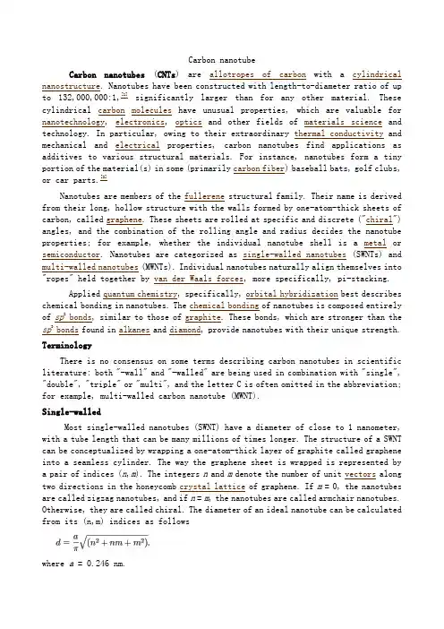
Carbon nanotubeCarbon nanotubes(CNTs) are allotropes of carbon with a cylindrical nanostructure. Nanotubes have been constructed with length-to-diameter ratio of up to 132,000,000:1,[1]significantly larger than for any other material. These cylindrical carbon molecules have unusual properties, which are valuable for nanotechnology, electronics, optics and other fields of materials science and technology. In particular, owing to their extraordinary thermal conductivity and mechanical and electrical properties, carbon nanotubes find applications as additives to various structural materials. For instance, nanotubes form a tiny portion of the material(s) in some (primarily carbon fiber) baseball bats, golf clubs, or car parts.[2]Nanotubes are members of the fullerene structural family. Their name is derived from their long, hollow structure with the walls formed by one-atom-thick sheets of carbon, called graphene. These sheets are rolled at specific and discrete ("chiral") angles, and the combination of the rolling angle and radius decides the nanotube properties; for example, whether the individual nanotube shell is a metal or semiconductor. Nanotubes are categorized as single-walled nanotubes (SWNTs) and multi-walled nanotubes(MWNTs). Individual nanotubes naturally align themselves into "ropes" held together by van der Waals forces, more specifically, pi-stacking.Applied quantum chemistry, specifically, orbital hybridization best describes chemical bonding in nanotubes. The chemical bonding of nanotubes is composed entirely of sp2 bonds, similar to those of graphite. These bonds, which are stronger than the sp3bonds found in alkanes and diamond, provide nanotubes with their unique strength.TerminologyThere is no consensus on some terms describing carbon nanotubes in scientific literature: both "-wall" and "-walled" are being used in combination with "single", "double", "triple" or "multi", and the letter C is often omitted in the abbreviation; for example, multi-walled carbon nanotube (MWNT).Single-walledMost single-walled nanotubes (SWNT) have a diameter of close to 1 nanometer, with a tube length that can be many millions of times longer. The structure of a SWNT can be conceptualized by wrapping a one-atom-thick layer of graphite called graphene into a seamless cylinder. The way the graphene sheet is wrapped is represented by a pair of indices (n,m). The integers n and m denote the number of unit vectors along two directions in the honeycomb crystal lattice of graphene. If m= 0, the nanotubes are called zigzag nanotubes, and if n= m, the nanotubes are called armchair nanotubes. Otherwise, they are called chiral. The diameter of an ideal nanotube can be calculated from its (n,m) indices as followswhere a = 0.246 nm.SWNTs are an important variety of carbon nanotube because most of their properties change significantly with the (n,m) values, and this dependence is non-monotonic (see Kataura plot). In particular, their band gap can vary from zero to about 2 eV and their electrical conductivity can show metallic or semiconducting behavior. Single-walled nanotubes are likely candidates for miniaturizing electronics. The most basic building block of these systems is the electric wire, and SWNTs with diameters of an order of a nanometer can be excellent conductors.[3][4] One useful application of SWNTs is in the development of the first intermolecular field-effect transistors(FET). The first intermolecular logic gate using SWCNT FETs was made in 2001.[5] A logic gate requires both a p-FET and an n-FET. Because SWNTs are p-FETs when exposed to oxygen and n-FETs otherwise, it is possible to protect half of an SWNT from oxygen exposure, while exposing the other half to oxygen. This results in a single SWNT that acts as a NOT logic gate with both p and n-type FETs within the same molecule.Single-walled nanotubes are dropping precipitously in price, from around $1500 per gram as of 2000 to retail prices of around $50 per gram of as-produced 40–60% by weight SWNTs as of March 2010Multi-walledMulti-walled nanotubes (MWNT) consist of multiple rolled layers (concentric tubes) of graphene. There are two models that can be used to describe the structures of multi-walled nanotubes. In the Russian Doll model, sheets of graphite are arranged in concentric cylinders, e.g., a (0,8) single-walled nanotube (SWNT) within a larger (0,17) single-walled nanotube. In the Parchment model, a single sheet of graphite is rolled in around itself, resembling a scroll of parchment or a rolled newspaper. The interlayer distance in multi-walled nanotubes is close to the distance between graphene layers in graphite, approximately 3.4 Å. The Russian Doll structure is observed more commonly. Its individual shells can be described as SWNTs, which can be metallic or semiconducting. Because of statistical probability and restrictions on the relative diameters of the individual tubes, one of the shells, and thus the whole MWNT, is usually a zero-gap metal.Double-walled carbon nanotubes (DWNT) form a special class of nanotubes because their morphology and properties are similar to those of SWNT but their resistance to chemicals is significantly improved. This is especially important when functionalization is required (this means grafting of chemical functions at the surface of the nanotubes) to add new properties to the CNT. In the case of SWNT, covalent functionalization will break some C=C double bonds, leaving "holes" in the structure on the nanotube and, thus, modifying both its mechanical and electrical properties. In the case of DWNT, only the outer wall is modified. DWNT synthesis on the gram-scale was first proposed in 2003[6]by the CCVD technique, from the selective reduction of oxide solutions in methane and hydrogen.The telescopic motion ability of inner shells[7] and their unique mechanical properties[8] permit to use multi-walled nanotubes as main movable arms in comingnanomechanical devices. Retraction force that occurs to telescopic motion caused by the Lennard-Jones interaction between shells and its value is about 1.5 nN.[9]TorusIn theory, a nanotorus is a carbon nanotube bent into a torus (doughnut shape). Nanotori are predicted to have many unique properties, such as magnetic moments 1000 times larger than previously expected for certain specific radii.[10]Properties such as magnetic moment, thermal stability, etc. vary widely depending on radius of the torus and radius of the tube.NanobudCarbon nanobuds are a newly created material combining two previously discovered allotropes of carbon: carbon nanotubes and fullerenes. In this new material, fullerene-like "buds" are covalently bonded to the outer sidewalls of the underlying carbon nanotube. This hybrid material has useful properties of both fullerenes and carbon nanotubes. In particular, they have been found to be exceptionally good field emitters. In composite materials, the attached fullerene molecules may function as molecular anchors preventing slipping of the nanotubes, thus improving the composite’s mechanic al properties.Graphenated carbon nanotubesGraphenated CNTs are a relatively new hybrid that combines graphitic foliates grown along the sidewalls of multiwalled or bamboo style CNTs. Yu et al.[12] reported on "chemically bonded graphene leaves" growing along the sidewalls of CNTs. Stoner et al.[13] described these structures as "graphenated CNTs" and reported in their use for enhanced supercapacitor performance. Hsu et al. further reported on similar structures formed on carbon fiber paper, also for use in supercapacitor applications.[14]The foliate density can vary as a function of deposition conditions (e.g. temperature and time) with their structure ranging from few layers of graphene (< 10) to thicker, more graphite-like.[15]The fundamental advantage of an integrated graphene-CNT structure is the high surface area three-dimensional framework of the CNTs coupled with the high edge density of graphene. Graphene edges provide significantly higher charge density and reactivity than the basal plane, but they are difficult to arrange in a three-dimensional, high volume-density geometry. CNTs are readily aligned in a high density geometry (i.e., a vertically aligned forest)[16] but lack high charge density surfaces—the sidewalls of the CNTs are similar to the basal plane of graphene and exhibit low charge density except where edge defects exist. Depositing a high density of graphene foliates along the length of aligned CNTs can significantly increase the total charge capacity per unit of nominal area as compared to other carbon nanostructures.[Nitrogen Doped Carbon NanotubesNitrogen doped carbon nanotubes (N-CNT's), can be produced through 5 main methods, Chemical Vapor Deposition,[18][19]high-temperature and high pressure reactions,gas-solid reaction of amorphous carbon with NHat high temeprature,[20]solid3reaction,[21] and solvothermal synthesis.[22]N-CNTs can also be prepared by a CVD method of pyrolysizing melamine under Ar at elevated temperatures of 800o C - 980o C. However synthesis via CVD and melamine results in the formation of bamboo structured CNTs. XPS spectra of grown N-CNT's reveals nitrogen in five main components, pyridinic nitrogen, pyrrolic nitrogen, quaternanry nitrogen, and nitrogen oxides. Furthermore synthesis temperature affects the type of nitrogen configuration.[23]Nitrogen doping plays a pivotal role in Lithium storage. N-doping provides defects in the walls of CNT's allowing for Li ions to diffuse into interwall space. It also increases capacity by providing more favorable bind of N-doped sites. N-CNT's are also much more reactive to metal oxide nanoparticle deposition which can further enhance storage capacity, especially in anode materials for Li-ion batteries. PeapodA Carbon peapod is a novel hybrid carbon material which traps fullerene inside a carbon nanotube. It can possess interesting magnetic properties with heating and irradiating. It can also be applied as an oscillator during theoretical investigations and predictions.Cup-stacked carbon nanotubesCup-stacked carbon nanotubes (CSCNTs) differ from other quasi-1D carbon structures, which normally behave as quasi-metallic conductors of electrons. CSCNTs exhibit semiconducting behaviors due to the stacking microstructure of graphene layers.[Extreme carbon nanotubesThe observation of the longest carbon nanotubes (18.5 cm long) was reported in 2009. These nanotubes were grown on Si substrates using an improved chemical vapor deposition (CVD) method and represent electrically uniform arrays of single-walled carbon nanotubes.[1]The shortest carbon nanotube is the organic compound cycloparaphenylene, which was synthesized in early 2009.[30][31][32]The thinnest carbon nanotube is armchair (2,2) CNT with a diameter of 3 Å. This nanotube was grown inside a multi-walled carbon nanotube. Assigning of carbon nanotube type was done by combination of high-resolution transmission electron microscopy(HRTEM), Raman spectroscopy and density functional theory(DFT) calculations.[33]The thinnest freestanding single-walled carbon nanotube is about 4.3 Å in diameter. Researchers suggested that it can be either (5,1) or (4,2) SWCNT, but exact type of carbon nanotube remains questionable.[34](3,3), (4,3) and (5,1) carbon nanotubes (all about 4 Å in diameter) were unambiguously identified using more precise aberration-corrected high-resolution transmission electron microscopy. However,they were found inside of double-walled carbon nanotubes.[碳纳米管碳纳米管(碳)是同素异形体的碳是圆柱形奈米结构。
碳纳米管对重金属吸附研究的英文文献Research on Heavy Metal Adsorption Using Carbon NanotubesCarbon nanotubes (CNTs) have attracted significant attention for their potential applications in environmental remediation due to their unique properties, such as high surface area, large aspect ratio, and outstanding mechanical and electrical properties. Among various environmental pollutants, heavy metals play an important role due to their toxicity, persistence, and the potential risk to human health and the ecosystem. CNTs have been reported to be effective in removing heavy metals from aqueous solutions.In recent years, researchers have explored the use of CNTs as adsorbents for various heavy metals, including lead, cadmium, chromium, mercury, and arsenic. The adsorption of heavy metals by CNTs is mainly governed by physical and chemical interactions, such as electrostatic attraction, van der Waals forces, and chemisorption. The efficiency of heavy metal removal is influenced by several factors, such as the pH of the solution, the concentration of heavy metals, the surface functionalization of CNTs, and the presence of other ions.The adsorption capacity of CNTs for heavy metals is dependent on their surface properties, such as the presence of functional groups. For example, carboxylic acid groups on CNTs can enhance the adsorption capacity for heavy metals through ion exchange and electrostatic interactions. Inaddition, the modification of CNTs with other materials, such as polymers and nanoparticles, can improve the selectivity and efficiency of heavy metal adsorption.CNTs have been demonstrated to be effective in removing heavy metals from contaminated water and soil. However, further research is needed to optimize their performance and understand the mechanisms of heavy metal adsorption. The use of CNTs for heavy metal remediation holds great promise, and may provide a cost-effective and sustainable solution for environmental cleanup.。
利用静电纺碳纳米纤维网制作锂离子二次电池的正极材料Chan Kim;刘呈坤
【期刊名称】《合成纤维》
【年(卷),期】2008(37)12
【摘要】利用聚合物溶液,通过静电纺以及热处理,制备了碳纳米纤维电极。
这种电极具有较大的可及表面积(纤维尺寸处于纳米级范围)、高碳纯度(无粘结剂)、相对较高的电导率、结构完整性、薄纤维网外观形态、较大的可逆容量(约450mAh.g-)1以及基本呈线性的电压分布。
可以想象,由于锂离子在这种活性材料里显著减小的扩散通道,该种新型碳材料将会成为制作大功率锂离子电池阳极材料(需要较高的电流)的理想候选材料。
【总页数】5页(P43-46)
【关键词】锂离子二次电池;碳纳米纤维;正极材料;纤维网;静电纺;制作;聚合物溶液;结构完整性
【作者】Chan Kim;刘呈坤
【作者单位】西安交大
【正文语种】中文
【中图分类】TQ342.742;TM912
【相关文献】
1.静电纺制备二氧化锡/碳纳米纤维锂离子电池负极材料的研究进展 [J], 周惠敏;李智勇;牛潇;夏鑫
2.静电纺丝法制备尖晶石型LiMn2O4纳米纤维锂离子电池正极材料 [J], 戴剑锋;闫兴山;田西光;李维学;王青
3.电纺自支撑空穴硅碳纳米纤维在高性能锂离子电池阳极材料中的应用 [J], 赵丹;刘书武;彭信文;胡唤;侯豪情
4.静电纺纳米材料在锂离子电池中的应用 [J], 张子浩
5.静电纺纳米纤维锂离子电池隔膜研究进展 [J], 张妍;于宾;翟梦真;王晓涵
因版权原因,仅展示原文概要,查看原文内容请购买。
气体扩散层纤维烧结钛
最近,科学家们发现了一种新型的气体扩散层材料——纤维烧结钛。
这种材料具有优异的气体扩散性能和高温稳定性,可广泛应用于太阳能电池、氢燃料电池等领域。
纤维烧结钛的制备过程相对简单,通过高温下的烧结和压缩等工艺,可以将钛粉末烧结成纤维状的材料。
这种材料具有均匀的孔隙分布和高度连通的气体通道,可实现优异的气体扩散性能。
此外,纤维烧结钛还具有良好的高温稳定性,能耐受高达1000℃的温度,并且具有较强的机械强度和韧性。
这些特性使得纤维烧结钛在太阳能电池和氢燃料电池等高温环境下的应用具有广阔的前景。
当前,科学家们正在进一步研究纤维烧结钛的制备工艺和性能优化,希望能够进一步扩大其在能源领域的应用。
- 1 -。
单壁碳纳米管(Single-Walled Carbon Nanotubes,SWCNTs)的扭曲形变可以显著影响其氢吸附性能。
以下是扭曲形变对氢吸附的一些影响:
表面积增加:扭曲形变可以导致SWCNTs的表面积增加,从而提供更多的吸附位点,增加氢气吸附的机会。
扭曲应力:扭曲形变引入了SWCNTs内部的应力,这可能会影响氢分子在纳米管表面的吸附和解离过程。
扭曲应力可能会改变氢分子与纳米管之间的相互作用,从而影响吸附能力。
孔径变化:扭曲形变可能导致SWCNTs的孔径发生变化。
由于氢分子的尺寸较小,孔径的变化可能会影响氢分子的进入和离开纳米管的能力。
极性变化:扭曲形变可以引起SWCNTs表面的极性变化。
由于氢分子是非极性分子,SWCNTs 表面的极性变化可能会影响氢分子与纳米管之间的相互作用,从而影响氢吸附能力。

碳纳米管天梯作文200字英文回答:Carbon nanotubes (CNTs) are a fascinating and innovative material with a wide range of applications. These cylindrical structures, composed of carbon atoms, have a unique set of properties that make them highly desirable in various fields.One of the most notable characteristics of CNTs istheir exceptional strength. They are about 100 times stronger than steel, yet much lighter. This makes themideal for applications where strength and lightweight are crucial, such as in aerospace engineering. For example, CNTs can be used to develop lighter and more fuel-efficient aircraft, reducing both cost and environmental impact.In addition to their strength, CNTs also possess excellent electrical conductivity. This property makes them valuable in electronics and electrical engineering. Forinstance, CNTs can be used to create faster and more efficient computer processors, leading to improved performance in various electronic devices. Furthermore, their electrical conductivity also makes them suitable for energy storage applications, such as in batteries and supercapacitors.Moreover, CNTs have a high aspect ratio, meaning their length is much greater than their diameter. This unique shape allows them to act as excellent reinforcements in composite materials. By incorporating CNTs into composites, the overall strength and stiffness of the material can be significantly enhanced. This has implications in the automotive industry, where lightweight and strong materials are essential for improving fuel efficiency and safety.Furthermore, CNTs have shown promise in the field of medicine. Their small size and high surface area-to-volume ratio make them ideal for drug delivery systems. CNTs can be functionalized with specific molecules to targetspecific cells or tissues, allowing for more precise and effective drug delivery. This has the potential torevolutionize the way we treat diseases and improve patient outcomes.Overall, carbon nanotubes are a remarkable material with a wide range of applications. Their exceptional strength, electrical conductivity, shape, and potential in medicine make them highly sought after in various industries.中文回答:碳纳米管(CNTs)是一种迷人且创新的材料,具有广泛的应用领域。
碳纳米管材料碳纳米管(Carbon nanotube,缩写CNT)与金刚石、石墨、富勒烯一样,是碳的一种同素异形体。
碳纳米管是在1991年1月由日本筑波NEC实验室的物理学家饭岛澄男使用高分辨率分析电镜从电弧法生产的碳纤维中发现的。
它是一种管状的碳分子,管上每个碳原子采取SP2杂化,相互之间以碳-碳σ键结合起来,形成由六边形组成的蜂窝状结构作为碳纳米管的骨架。
每个碳原子上未参与杂化的一对p电子相互之间形成跨越整个碳纳米管的共轭π电子云。
按照管子的层数不同,分为单壁碳纳米管和多壁碳纳米管。
管子的半径方向非常细,只有纳米尺度,几万根碳纳米管并起来也只有一根头发丝宽,碳纳米管的名称也因此而来。
而在轴向则可长达数十到数百微米。
碳纳米管不总是笔直的,局部可能出现凹凸的现象,这是由于在六边形结构中混杂了五边形和七边形。
出现五边形的地方,由于张力的关系导致碳纳米管向外凸出。
如果五边形恰好出现在碳纳米管的顶端,就形成碳纳米管的封口。
出现七边形的地方碳纳米管则向内凹进。
碳纳米管的性质碳纳米管的分子结构决定了它具有一些独特的性质。
由于巨大的长径比(径向尺寸在纳米量级,轴向尺寸在微米量级),碳纳米管表现为典型的一维量子材料,它的电子波函数在管的圆周方向具有周期性,在轴向则具有平移不变性,大大纯化了理论工作,并做出了一些预言。
理论预言,碳纳米管具有超常的强度、热导率、磁阻,且性质会随结构的变化而变化,可由绝缘体转变为半导体、由半导体变为金属;具有金属导电性的碳纳米管通过的磁通量是量子化的,表现出阿哈罗诺夫-玻姆效应(A-B效应)。
力学性质由于碳纳米管中碳原子采取SP2杂化杂化,相比SP3杂化杂化,SP2杂化中S轨道成分比较大,使碳纳米管具有高模量、高强度。
碳纳米管的硬度与金刚石相当,却拥有良好的柔韧性,可以拉伸。
目前在工业上常用的增强型纤维中,决定强度的一个关键因素是长径比,即长度和直径之比。
目前材料工程师希望得到的长径比至少是20:1,而碳纳米管的长径比一般在1000:1以上,是理想的高强度纤维材料。
单壁碳纳米管缩写
单壁碳纳米管(SWCNT)是一种由碳原子构成的纳米材料,具有非常独特的物理和化学性质。
SWCNT由一个单层碳原子薄膜卷曲而成,形成了一个中空的圆柱形结构。
这种结构使得SWCNT具有许多独特的性质和应用潜力。
SWCNT具有非常高的机械强度和弹性,使其成为一种理想的材料用于制备高强度纤维和复合材料。
它的强度比钢高几倍,而重量却非常轻,这使得SWCNT在航空航天和汽车制造等领域具有广阔的应用前景。
此外,SWCNT还具有优异的导电性能,使其成为高性能传感器和电子器件的理想材料。
SWCNT还具有优异的热导性能。
研究表明,SWCNT的热导率比铜高几倍,使其成为一种理想的热界面材料。
在微电子领域,SWCNT 被广泛应用于制备高效的散热器和热传导材料,可以有效地提高芯片的散热效果,提高设备的工作效率和可靠性。
SWCNT还具有非常好的光学性能。
由于其独特的结构和能带结构,SWCNT具有可调控的光学特性,可以用于制备高性能的光电器件和光学传感器。
例如,利用SWCNT的特殊吸收光谱,可以制备出高效的太阳能电池和光电探测器。
SWCNT还具有一些其他特殊的性质和潜在应用。
例如,SWCNT在生物医学领域有广泛的应用前景,可以用于制备高灵敏度的生物传
感器和药物载体。
此外,SWCNT还具有良好的化学稳定性和生物相容性,可以用于制备高性能的催化剂和药物递送系统。
SWCNT作为一种新型纳米材料,具有许多独特的性质和广泛的应用潜力。
随着对SWCNT的深入研究和理解,相信它将在各个领域发挥重要作用,为人类的生活和科技进步带来新的突破。
新型镍铁电弛电极材料提高充放电速度近千倍
佚名
【期刊名称】《电源技术》
【年(卷),期】2012(36)9
【摘要】美国斯坦福大学最近发明了一种新型镍铁电池电极材料,能在2分钟内完成充电,30秒内完成放电.提高充放电速度近千倍。
【总页数】1页(P1260-1260)
【关键词】放电速度;电极材料;镍铁;美国斯坦福大学;铁电;电池;充电
【正文语种】中文
【中图分类】TM912.2
【相关文献】
1.新型记录材料—铁电薄膜材料与铁电存储器 [J], 卢德新;黄龙波
2.斯坦福大学华人师生新发明提高充放电速度近千倍 [J], 无
3.电沉积制备镍−铁−钨合金析氢电极的工艺研究 [J], 徐超; 周建波; 崔小莹; 肖荣; 付薪菱
4.一步电沉积镍铁硫化物纳米复合电极 [J], 马骏;孟祥康;苏冬云;丁中武;褚岩
5.复旦大学研发出新型纳米钛酸锂电极材料充放电循环数千次以上,电池寿命大大延长 [J],
因版权原因,仅展示原文概要,查看原文内容请购买。
单壁碳纳米管大量制备的新方法和工艺条件引言单壁碳纳米管(Single-walled carbon nanotubes,SWCNTs)是一种具有独特结构和优异性能的纳米材料,在电子学、光电子学、催化剂等领域具有广泛的应用前景。
然而,传统的制备方法存在成本高、产量低、质量不稳定等问题,因此迫切需要一种新的方法和工艺条件来实现单壁碳纳米管大量制备。
现有方法的局限性目前常用的单壁碳纳米管制备方法包括化学气相沉积法(Chemical Vapor Deposition,CVD)、电弧放电法(Arc Discharge),以及激光热解法(Laser Ablation)。
这些方法虽然可以获得一定数量的单壁碳纳米管,但存在以下局限性:1.成本高:传统方法需要昂贵的原料和设备,并且能源消耗大。
2.产量低:传统方法通常只能获得少量的单壁碳纳米管,无法满足大规模应用需求。
3.质量不稳定:传统方法制备的单壁碳纳米管质量不稳定,存在管径分布不均匀、结构缺陷等问题。
新方法的提出为了克服传统方法的局限性,我们提出了一种基于化学气相沉积法的新方法来实现单壁碳纳米管的大量制备。
该方法结合了催化剂设计、反应条件控制和后处理技术,可以有效地提高单壁碳纳米管的产量和质量。
催化剂设计催化剂在单壁碳纳米管制备过程中起到关键作用。
我们采用了一种新型催化剂,具有以下特点:1.高活性:新型催化剂具有较高的催化活性,可以促进碳源气体在催化剂表面的解离和重组,有利于单壁碳纳米管的生长。
2.选择性:新型催化剂能够选择性地促进单壁碳纳米管的生长,减少多壁碳纳米管和其他杂质的生成。
3.稳定性:新型催化剂具有良好的热稳定性和抗毒性,在长时间反应中保持较高的催化活性。
反应条件控制为了实现单壁碳纳米管的大量制备,我们对反应条件进行了优化。
主要包括以下方面:1.温度控制:通过精确控制反应温度,可以实现单壁碳纳米管的生长和其他副反应的抑制。
我们采用了高温炉进行反应,温度范围为800-1000摄氏度。
Research on the properties of carbonnanotubesCarbon nanotubes (CNTs) are unique materials with extraordinary mechanical, electrical and thermal properties. At the nanoscale, they exhibit a combination of properties that make them ideal for use in a wide range of applications.Properties of Carbon NanotubesOne of the most remarkable properties of CNTs is their strength. CNTs are 100 times stronger than steel, five times lighter than aluminum, and 10 times stronger than Kevlar. This strength is due to the strong covalent bonds between the carbon atoms in the nanotube structure. These bonds allow the nanotubes to resist deformation and fracture under high stresses.Another important property of CNTs is their electrical conductivity. CNTs are excellent conductors of electricity and can carry large amounts of current without overheating. This property makes them ideal for use in electronics, such as transistors, sensors, and interconnects.CNTs are also excellent thermal conductors. They can transport heat at rates that exceed those of any other known material. This thermal conductivity makes them ideal for use in heat sinks, which are used to cool electronic devices.Types of Carbon NanotubesThere are two main types of CNTs: single-walled nanotubes (SWNTs) and multi-walled nanotubes (MWNTs). SWNTs are thin tubes made up of a single layer of carbon atoms. They are extremely strong and have high electrical conductivity. MWNTs, on the other hand, are made up of several layers of carbon atoms and are not as strong or conductive as SWNTs.Applications of Carbon NanotubesThe unique properties of CNTs have led to their use in a variety of applications. One of the most promising applications for CNTs is in the field of electronics. The high electrical conductivity and small size of CNTs make them ideal for use in transistors and other electronic components.CNTs are also being used in the field of medicine. Researchers are exploring the use of CNTs in drug delivery systems, as well as in the development of new imaging techniques.In addition, CNTs have potential applications in the field of energy. They may be used in the development of new, lightweight batteries and in the production of more efficient solar cells.ConclusionThe unique properties of CNTs make them one of the most promising materials for a wide range of applications. The strength, electrical conductivity, and thermal conductivity of these materials are unparalleled at the nanoscale. As researchers continue to explore the properties of CNTs, it is likely that new applications and uses for these materials will be discovered.。
碳纳米管阵列红外线吸波材料英文回答:Carbon nanotube (CNT) arrays have attracted significant attention as infrared (IR) absorbing materials due to their unique properties. CNTs are cylindrical structures made of carbon atoms arranged in a hexagonal lattice. They have a high aspect ratio, excellent electrical and thermal conductivity, and a large surface area. These properties make CNTs ideal for applications in various fields, including electronics, energy storage, and sensing.In terms of IR absorption, CNT arrays have shown great potential. The strong absorption of IR radiation by CNTs is mainly attributed to their unique electronic structure and the presence of energy bands. When IR radiation interacts with CNTs, it can excite the electrons in the energy bands, leading to the absorption of the IR energy. The absorbed energy is then converted into heat, resulting in a decrease in the IR reflectance.One of the advantages of CNT arrays as IR absorbing materials is their tunability. By controlling the diameter, length, and density of the CNTs, the absorption properties can be tailored to specific IR wavelengths. This tunability allows for the design of CNT arrays with high absorption efficiency in desired IR ranges. For example, CNT arrayswith a specific diameter and density can be optimized for absorption in the mid-IR range, which is important for applications such as thermal imaging and gas sensing.Moreover, the use of CNT arrays as IR absorbingmaterials offers the possibility of integrating them into various devices and systems. CNT arrays can be easily grown on different substrates, including silicon, glass, and flexible materials. This enables their integration into existing technologies, such as IR detectors and solar cells, enhancing their performance. Additionally, CNT arrays canbe patterned into different shapes and sizes, allowing for the development of customized IR absorbing structures for specific applications.In summary, CNT arrays have emerged as promising materials for IR absorption due to their unique properties, tunability, and integration capabilities. Their ability to efficiently absorb IR radiation makes them suitable for a wide range of applications, from thermal imaging to sensing. The development of CNT arrays as IR absorbing materials opens up new possibilities for the design and improvementof IR-based technologies.中文回答:碳纳米管阵列作为红外线吸波材料,由于其独特的性质,引起了广泛的关注。
Suspended Carbon Nanotube Quantum Wireswith Two GatesJien Cao, Qian Wang, Dunwei Wang and Hongjie Dai*Department of Chemistry and Laboratory for Advanced Materials, Stanford University,Stanford, CA 94305Suspended single-walled carbon nanotube devices comprised of high quality electrical contacts and two electrostatic gates per device are obtained. Compared to nanotubes pinned on substrates, the suspended devices exhibit little hysteresis related to environmental factors and manifest as cleaner Fabry-Perot interferometers or single electron transistors. The high-field saturation currents in suspended nanotubes related to optical phonon or zone boundary phonon scattering are significantly lower due to the lack of efficient heat sinking. The multiple gate design may also facilitate future investigation of electromechanical properties of nanotube quantum systems.* Correspondence to hdai@In recent years, successful fabrication of suspended single-walled carbon nanotube (SWNT) devices with electrical wiring has facilitated the investigation of the electrical, mechanical and electromechanical properties of these novel wires.[1-6] Here, we report a reliable method for the fabrication of suspended SWNT devices with improved metal-nanotube contacts and a useful double-gate design. These devices have led to the revelation of interesting electrical transport properties of nanotubes that are distinct from those pinned on substrates.The structure of our suspended SWNT device is shown in Figure 1, consisting of a nanotube suspended over a trench by two pre-formed source (S) and drain (D) metal electrodes, a metal local-gate (V GL) at the bottom of the trench and a global Si back-gate (V GB). Device fabrication started with deposition of a 38 nm thick Si3N4 film on a p-type SiO2/Si wafer (SiO2 thickness = 500 nm). Electron-beam lithography (EBL) was used to define the local-gate pattern, dry-etching and wet-etching were used to open a window in the EBL resist and Si3N4 film and to further etch ~300 nm deep into the SiO2 to form a trench with undercut (Figure 1a). Electron beam deposition of Pt/W (25 nm Pt; 5 nm W as sticking layer) followed by lift-off was then carried out to complete the formation of the trench with a Pt/W local gate electrode at the bottom. A second step EBL was performed to define the S/D pattern, followed by deposition of 5 nm W (as the sticking layer) and 25 nm Pt, and then liftoff. The region across the trench was written into a continuous stripe in the second EBL step. After metal deposition and liftoff, the stripe gave rise to the S/D electrodes separated by the trench. The S/D extended to the two edges of the trench and were electrically isolated from the local Pt gate due to undercutting in the sidewall of the trench. Finally, a third EBL step was carried out topattern catalyst islands on top of the S/D. Chemical vapor deposition (CVD) was then used to grow SWNTs to bridge the electrode pairs on the wafer chip.[4,5] Low yield growth conditions were used (800 – 825 °C) to afford mostly single tubes bridging the S/D pairs, as confirmed by scanning electron microscope (SEM) after electrical measurements of the devices. The results presented here were all obtained from individual suspended SWNT devices.Earlier, we described CVD growth of SWNTs across pre-formed Mo electrodes for electrical and electromechanical devices.[4] Mo was chosen as the S/D electrode material due to its compatibility with SWNT growth and the ability of dry-etching of Mo for electrode patterning. In the current work, our fabrication process does not involve dry-etching of metal and thus allows a wider choice of refractory metals. We succeeded in using refractory metals W and Pt/W (W as adhesive layer for Pt) as preformed electrodes and found that the typical resistance of our individual suspended SWNT devices was in the range of 10 – 50 kΩ (Figure 2 to 4). The contact resistance appeared higher than devices with nanotubes lying on substrates with Pd top-contacts[7,14], but lower compared to other suspended SWNT devices including those with preformed Mo electrodes[4] or top-contacted Au electrodes[3].We observed several interesting properties for suspended SWNTs that are distinct from nanotubes pinned on substrates. The first is that the suspended SWNT devices are “hysteresis-free”, for all the suspended devices we have measured (more than 100 devices): they show a small amount of hysteresis in current vs. gate (I sd-V GL) sweeps right after CVD growth, but the hysteresis completely disappears immediately after (in a few seconds) the devices are placed in Ar, dry air or vacuum (Figure 2a inset). This differsfrom nanotubes resting on SiO 2 substrates and is attributed to the lack of water molecules adsorbed on nanotubes in a dry environment, and that suspended nanotubes are free from intimate contact with water molecules adsorbed on SiO 2 substrate.[8]The second interesting property of the suspended nanotube devices is that they appear to be ‘cleaner’ quantum systems than nanotubes on substrates. At low temperatures, the devices (length of suspension investigated here L ~ 400-700 nm) exhibited characteristics corresponding to single quantum dots or interference resonators, without complex dots-in-series behavior often observed for tubes on substrates. A representative small band-gap semiconducting (SGS) SWNT [9] device is shown in Figure 2. The temperature dependence of the dip in the I sd -V GL in Figure 2a shows activated transport. A small band gap of E g ~ 70 meV is obtained by fitting the conductance (G ) at the dip to exp(-E g /2K B T ). Transport through the p- and n-channels of the SWNT appear asymmetric, with higher conductance for the p-channel. At T =100 K, the subthreshold swings are S ~ 150 mV/decade and 1.2 V/decade for the p- and n-subthreshold regions respectively (Figure 2a). At this temperature, the expected S is [10] decade mV 13010e kT 1S GL/ln ≈⋅=α if the Schottky barrier (SB) height is ~0, where αGL ~ 0.14 is the local-gate efficiency factor (shift in Fermi level for a gate voltage change of ∆V GL = 1V) as deduced later. Comparison of p- and n-channels’ subthreshold swings to the theory predicted value suggests near zero and appreciable positive SBs [7,11] to the valence and conduction bands respectively between the SGS tube and the S/D electrodes. This is also consistent with the higher p-channel conductance than the n-channel.A lock-in technique (503Hz, 50µV S/D bias) was used to perform dI sd /dV sd measurements for the p-channel of our suspended-SWNT devices. When the local gatewas set at a constant of V GL = –3.0 V, dI sd/dV sd vs. V GB and V sd exhibits an interference pattern with conductance peaks (~ 45µS, 1.4e2/h) and valleys (~ 15µS, 0.5e2/h) (Figure 2b). The conductance peaks at V sd ~ 2.8 mV corresponds to the length of the nanotube L ~ 620 nm very well through V c = hνF/2L ~ 1.67meV/L(µm), suggesting that the p-channel of the SGS tube behaves as a well-defined Fabry-Perot interference wave guide or resonator.[12-14]The n-channel of the device exhibits clear Coulomb blockade (CB) behavior (Figure 2c), as probed by fixing V GL = 3.5V and sweeping V GB. The positive SBs to the conduction band give rises to two contact barriers that confine the nanotube quantum dot (QD). Clean periodic CB features corresponding to a single QD were observed with a charging energy of E c~13 meV. Since the length of the nanotube is L = 620 nm, a charging energy of ~13 meV is higher than E c~ 5 meV/L(µm) ~ 8 meV typical for nanotube QDs on SiO2 substrates[15]. This is due to the low dielectric constant of the medium (air/vacuum) surrounding the suspended nanotube (compared to SiO2 for tubes on substrate), which gives rise to a lower total capacitance and thus higher charging energy for the suspended nanotube. We find that E c ~ 8 meV/L(µm) describes the charging energies of suspended SWNTs well. The local-gate efficiency is estimated to be αGL= E c/∆V GL = 0.15 where ∆V GL ~ 87 mV is the period of Coulomb oscillation in Figure 2c. We also observed extra lines outside the CB diamonds (Figure 2c inset), corresponding to discrete excited quantum confined states along the length of the tube. The energy scale of the lines is ~ 2 meV, matching the discrete level spacing[15] of ∆E ~1 meV/L(µm) in the nanotube.We note that clean and homogeneous quantum interferometers and QDs are reliably observed with large numbers of our suspended-SWNT devices, at much higher frequency than tubes on substrates with similar lengths between S/D electrodes. This suggests few defects in our SWNTs at the sub-micron length scale and that the lack of substrate-nanotube interactions can prevent the break up of nanotubes into segments due to local chemical effects or mechanical strains.A third interesting feature of our suspended nanotube devices is the two-gate configuration. We have measured the conductance of the sample versus both gates, as shown in Figure 3. Conductance features (e.g., peaks, valleys) appear as parallel lines in the 2-D plot, indicating the two gates are independent and additive. The slopes of the bright lines in G vs. V GL and V GB can be used to deduce the ratio between the efficiencies of the two gates, αGL /αGB ~ 30. That is, the local-gate is ~ 30 times more efficient than the back-gate, or the local gate capacitanceC GL ~ 30C GB . The low efficiency of the back-gate can be understood due to screening of the local gate (Figure 1). Note that the local gate capacitance can be predicted by [16] ()F 105r h 2L 2C 180GL −×≈≈/ln πεε, where ε = 1, r ~ 1 nm is the nanotube radius and h = 300 nm is the distance between the local gate and the nanotube (depth of trench). This suggests that C GB ~ C GL /30 ~ 1.7×10⁻¹⁹ F , which is in reasonable agreement with C GB ~ 0.9×10⁻¹⁹ F as measured from the CB data in the inset of Figure 2c. A potentially powerful aspect of the two-gate configuration is that under appropriate conditions, the local gate electrostatic coupling could become sufficiently strong to induce appreciable mechanical strain in the nanotube. The less effective global back-gate could then be used as a sweeping gate to characterize the electromechanical effects to the suspended nanotube quantum dot. We are currently pursuing thisinteresting possibility, especially for electromechanical measurements at low temperatures.The fourth interesting result obtained with our suspended SWNT devices concerns with the high-bias transport properties of nanotubes when they are not resting on underlying substrates. This can shed light into the properties of nanotubes in their intrinsic states without significant roles played by the environment. For all of the suspended nanotubes that we have measured (L ~ 400 – 700nm, resistance ~ 40 - 60 kΩ), we have consistently observed current saturation at the I sat ~ 8 µA level, which is significantly lower than ~ 15-20 µA saturation currents for nanotubes (with similar resistance) lying on substrates. Since current saturation at high fields in SWNTs is caused by scattering of energetic (~0.2 eV) optical or zone-boundary phonons,[17-19] the lower saturation current in a suspended nanotube can be understood by the lack of a proximal thermally conductive SiO2 substrate for ‘heat sinking’. Electrical heating is rapid in suspended nanotubes and the heat cannot be efficiently conducted away to the surrounding. This leads to increased acoustic phonon scattering, which is responsible for the observed current decrease under increasing bias (slight negative differential conductance feature in Figure 4).In summary, a reliable method has been developed to obtain suspended SWNT devices with relatively good electrical contacts. Compared to nanotubes lying on substrates, the suspended devices exhibit little hysteresis behavior and manifest as well-defined single quantum dots or resonators. The high-field saturation current caused by optical phonon scattering in suspended nanotubes is low. The multiple gate design may facilitate future investigation of electromechanical properties of nanotubes.This work was supported by MARCO MSD, a NSF-NIRT grant, SRC/AMD, DARPA/MTO, a Packard Fellowship, Sloan Research Fellowship and a Camille Dreyfus Teacher-Scholar Award.Figure Captions:Figure 1. (a) A schematic device structure. (b) SEM images of a device consisting of a single suspended SWNT and two gates (local gate V GL and global back-gate V GB).Figure 2. (a) I sd-V GL (current vs. local gate) characteristics for a suspended small band-gap SWNT device (with back-gate grounded) recorded from room temperature to 1.5 K (curve with drastic oscillations) using V sd=1mV bias. Inset: Hysteresis free double-sweep I sd-V GL data recorded at room temperature. The two arrows correspond to back-and-forth gate sweeps. The I sd-V GL curves recorded under the two sweep-directions overlap with each other. (b) A 2-D plot of conductance dI sd/dV sd vs. V GB and bias V sd(V GL fixed at -3.0V) for the p-channel of the SWNT. The color scale bar for the conductance at the right of the graph is in unit of e2/h. (c) A zoom-in of (a) in a smaller gate range V GL of 2 - 5V (bias=1mV) for the n-channel of the SWNT. Inset: A 2-D plot of dI sd/dV sd vs. V GB and V sd (V GL set at 3.5 V). The two lines were drawn to highlight discrete electronic state due to quantum confinement along the tube length. Dark to bright colors correspond to conductance in the range of 0 to 0.2e2/h.Figure 3. A 2-D plot of conductance G vs. V GL and V GB with V sd = 1 mV. The bright color corresponds to high conductance of 1.4 e2/h and dark corresponds to zero conductance.Figure 4.I sd-V sd curve recorded for a suspended SWNT up to a high bias of V sd = 2 V. The dashed line was drawn to highlight the slight negative differential conductance behavior.References[1] Tombler, T.W.; Zhou, CW.; Alexseyev, L.; Kong, J.; Dai, H.J.; Lei, L.; Jayanthi,C.S.; Tang, M.J.; Wu, S.Y. Nature2000, 405, 769.[2] Walters, D.A.; Ericson, L.M.; Casavant, M.J.; Liu, J.; Colbert, D.T.; Smith, K.A.; Smalley, R.E., Appl. Phys. Lett.1999, 74, 3803.[3] Nygard, J.; Cobden, D.H., Appl. Phys. Lett.2001, 79, 4216.[4] Franklin, N.R.; Wang, Q.; Tombler, T.W.; Javey, A.; Shim, M.; Dai, H.J., Appl. Phys. Lett.2002, 81, 913.[5] Cao J., Wang Q., Dai H.J., Phys. Rev. Lett.2003, 90, 157601.[6] Minot, E.D.; Yaish, Y.; Sazonova, V.; Park, J.Y.; Brink, M.; McEuen, P.L., Phys. Rev. Lett.2003, 90, 156401.[7] Javey, A.; Guo, J.; Wang, Q.; Lundstrom, M.; Dai, H.J., Nature2003,424, 654.[8] Kim, W.; Javey, A.; Vermesh, O.; Wang, Q.; Li, Y.M.; Dai, H.J., Nano Lett. 2003,3, 193.[9] Zhou, C.W.; Kong, J.; Dai, H.J., Phys. Rev. Lett.2000,84, 5604.[10] Sze, S.M., Physics of semiconductor devices; Wiley, New York, 1981.[11] Heinze, S.; Tersoff, J.; Martel, R.; Derycke, V.; Appenzeller, J.; Avouris, P., Phys. Rev. Lett.2002, 89, 6801.[12] Liang, W.; Bockrath, M.; Bozovic, D.; Hafner, J.; Tinkham, M.; Park, H., Nature 2001, 411, 665.[13] Kong, J.; Yenilmez, E.; Tombler, T. W.; Kim, W.; Liu, L.; Jayanthi, C. S.; Wu, S. Y.; Laughlin, R. B.; Dai, H. Phys. Rev. Lett.2001, 87, 106801.[14] Mann, D.; Javey, A.; Kong, J.; Wang, Q.; Dai, H.J., Nano Lett.2003,3, 1541.[15] Nygard, J.; Cobden, D.H.; Bockrath, M.; McEuen, P.L.; Lindelof, P.E., Appl. Phys. A1999,69, 297.[16] Ramo S., Whinnery J.R., Duzer T.V., Fields and Waves in Communication Electronics; Wiley, New York, 1994.[17] Yao, Z.; Kane, C.L.; Dekker, C., Phys. Rev. Lett.2000, 84, 2941.[18] Javey A., Guo J., Paulsson M., Wang Q., Mann D., Lundstrom M., Dai H.J., Phys. Rev. Lett.2004, 92, 106804.[19] Park J.Y., Rosenblatt S., Yaish Y., Sazonova V., Ustunel H., Braig S., Arias T.A., Brouwer P.W., McEuen P.L., Nano Lett.2004, 4, 517.Text for Table of ContentsDevices comprised of as-grown suspended single-walled carbon nanotube, high quality metal electrical contacts and two electrostatic gates per device are obtained for the first time. As shown in the graph, the length of the nanotube is fully suspended between two mesa metal contacts and free of any nanotube-substrate interaction. These suspended nanotube devices are ultra "clean" quantum systems and provide unique opportunity to investigate the intrinsic properties of nanotubes including transport behavior at high bias. In addition, the multiple gate design may also facilitate future work on electromechanical properties of suspended nanotube quantum systems.Keywords:Carbon nanotubes, Quantum dots, Electron TransportSourceSi3N4Pt/WSiO2Source Drain(b)Figure 115604020I s d /n A-4-2024V GL /VFigure 2-10-5510V s d /m V-1010V GB /V(b)403020100I s d /n A5432V GL /V(c)20105V GB /VFigure 3-505V G B /V42-2V GL/V86420I s d /µA21V sd /VFigure 4。