Chapter 7 System life cycle methodologies-外文翻译
- 格式:pdf
- 大小:693.40 KB
- 文档页数:12
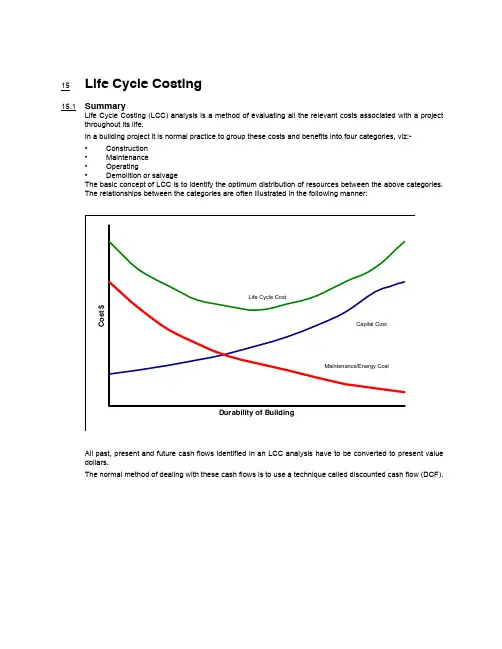
15Life Cycle Costing15.1SummaryLife Cycle Costing (LCC) analysis is a method of evaluating all the relevant costs associated with a project throughout its life.In a building project it is normal practice to group these costs and benefits into four categories, viz:-•Construction •Maintenance •Operating •Demolition or salvageThe basic concept of LCC is to identify the optimum distribution of resources between the above categories.The relationships between the categories are often illustrated in the following manner:All past, present and future cash flows identified in an LCC analysis have to be converted to present value dollars.The normal method of dealing with these cash flows is to use a technique called discounted cash flow (DCF).15.2Discounted Cash Flow—DCFDiscounted cash flow is derived from the compound interest formula. It is based on the assumption that if the right to receive money, or the obligation to pay out money, is deferred into the future, then the present value of this future sum of money is reduced. The amount of this reduction on the interest selected is calculated at a compound rate.Example: What is the single present worth or value of the obligation to pay a bill with a present value of $2,000 in 10 years time. Assume 7% interest.The answer can be calculated by using the reciprocal of the compound interest formula as follows:Where P = a present sum of money, F = a future sum of money (equivalent to P at the end of N periods of time at an interest rate of i ), i = interest rate, N = number of interest periods. Thus, present worth = $1,016.70Spreadsheet solutions for the present worth formula are available for a range of values of parameters i and N.Spreadsheet solutions are also available for other discounting formulae such as Uniform Present Worth,Present Worth of Periodic Payments, Annual Equivalent of Initial Payments and Annual Equivalent of Periodic Payments.15.3Example of LCC AnalysisLCC analysis is primarily suited for the economic comparison of alternatives. LCC is used to select the design solution which will give the most appropriate in-use characteristics throughout the life of the building.The following data refers to two air-conditioning systems X and Y , each capable of producing identical environmental conditions, but having differing capital and running costs and life expectancy.Assume an interest rate of 12% and investment period of 30 years. Refer to page 610, and Refer to page 611.Life Cycle Costing Example Assumptions and Details System X System Y Capital cost $115,600 $158,800Life of plant10 years 15 years Annual fuel and maintenance costs, after deductions for tax allowance $37,800$28,200Salvage value of plant$3,000$7,000P F 11i +()N -------------------=P 2000110.07+()10-------------------------------×=P 200011.9671514---------------------------×=P 20000.5083492×=System X—Cash Flow TableYear Details CashOutflowCashInflowNet CashFlowPresentWorthof $1DiscountRate 12%NPW ofoutflow $10Install air-conditioning System X115,6000-115,600 1.0000115,600 1Annual fuel and maintenance costs37,8000-37,800.892933,752 237,8000-37,800.7972 30,134 337,8000-37,800.7118 26,906 437,8000-37,800.6355 24,022 537,8000-37,800.5674 21,448 637,8000-37,800.5066 19,150 737,8000-37,800.4523 17,097 837,8000-37,800.4039 15,367 937,8000-37,800.3606 13,631 10Replacement air conditioning system115,600Salvage value3,000Annual fuel and maintenance costs37,8000-150,400.322048,429 1137,8000-37,800.2875 10,868 1237,8000-37,800.2567 9,703 1337,8000-37,800.2292 8,664 1437,8000-37,800.2046 7,734 1537,8000-37,800.1827 6,906 1637,8000-37,800.1631 6,165 1737,8000-37,800.1456 5,504 1837,8000-37,800.1300 4,914 1937,8000-37,800.1161 4,389 20Replacement air conditioning system115,600Salvage value3,000Annual fuel and maintenance costs37,8000-150,400.103715,597 2137,8000-37,800.0926 3,500 2237,8000-37,800.0826 3,122 2337,8000-37,800.0736 2,790 2437,8000-37,800.0659 2,491 2537,8000-37,800.0588 2,223 2637,8000-37,800.0525 1,985 2737,8000-37,800.0469 1,773 2837,8000-37,800.0419 1,584 2937,8000-37,800.0374 1,414 3037,8000-37,800.0334 1,263 Total Present Worth Costs$468,025System Y—Cash Flow TableYear Details CashOutflow CashInflowNet CashFlowPresentWorthof $1Discount Rate12%NPW ofoutflow $10Install air-conditioning system Y158,8000-158,800 1.0000158,800 1Annual fuel and maintenance costs28,2000-28,200.892925,180 228,2000-28,200.7972 22,481 328,2000-28,200.7118 20,073 428,2000-28,200.6335 17,921 528,2000-28,200.5674 16,001 628,2000-28,200.5066 14,286 728,2000-28,200.4523 12,755 828,2000-28,200.4039 11,390 928,2000-28,200.3606 10,169 1028,2000-28,200.3220 9,080 1128,2000-28,200.2875 8,106 1228,2000-28,200.2567 7,239 1328,2000-28,200.2292 6,463 1428,2000-28,200.2046 5,770 15Replacement air conditioning system158,800Salvage value7,000Annual fuel and maintenance costs28,2000-180,000.182732,886 1628,2000-28,200.1631 4,599 1728,2000-28,200.1456 4,106 1828,2000-28,200.1300 3,666 1928,2000-28,200.1161 3,274 2028,2000-28,200.1037 2,924 2128,2000-28,200.0926 2,611 2228,2000-28,200.0826 2,329 2328,2000-28,200.0738 2,081 2428,2000-28,200.0659 1,858 2528,2000-28,200.0588 1,658 2628,2000-28,200.0525 1,481 2728,2000-28,200.0469 1,323 2828,2000-28,200.0419 1,182 2928,2000-28,200.0374 1,055 3028,2000-28,200.0334 942 Total Present Worth Costs $413,689Note: for illustrative purposes the foregoing calculations are presented in full.15.4Alternative calculation methodBy using uniform and aggregated present worth tables the calculations can be presented as follows:The foregoing example illustrates that although X is initially a lower capital investment than Y , X has a higher LCC than Y , due to increased running and maintenance costs, over a 30 year investment period, at a discount rate of 12%.15.5LCC Analysis GenerallyPrior to making an investment decision it is imperative to test the robustness of an LCC analysis to changes in the key parameters of the investment model. This can be done by selecting minimum and maximum value for interest rates, system lives, investment periods, etc.As previously mentioned, LCC analysis is best used in a comparative situation to provide an approximate answer to a precise question rather than a precise answer to an approximate question.Alternative calculation methodSystem XSystem Y Capital costs (in $)115,600158,800Replacement costsX–system life 10 years.Assume replacement at year 10 and year 20 $(115,600–3,000) x 0.425747,934Y–system life 15 years.Assume replacement at year 15 $(158,800–7,000) x 0.182727,734Running costsX–$37,800 x 8.055304,479Y–$28,200 x 8.055227,151Total Present Worth Costs$468,103$413,685。

0引言随着产业技术变革及内外部环境的变化,创新能力提升已经成为社会发展的重要主题。
国家层面从不同角度逐步深化科技创新体系和机制改革,以加大资金等资源投入和政策扶持力度,加快建设以企业为主体、市场为导向、产学研用深度融合的科技创新体系。
在依靠科技进步和产品技术创新驱动各行各业高质量发展的新阶段,企业逐步成了基础研究、应用研究和试验发展等创新项目实施的主力军,并站上了科技创新的主舞台。
如政府、行业各层级重点研发攻关项目均不同程度要求企业的参与程度,部分项目则明确需要由企业牵头,联合高等院校、科研院所联合建立研究团队承担项目。
近年来,企业科技管理能力和科研项目管理水平总体有了较大改观,但在科研项目立项、实施等不同阶段仍存在诸多短板,进一步提升科研项目组织实施效率方面尚需要进一加强管理。
1企业科研项目管理特点1.1项目实施侧重于实现经济效益企业作为最基本、最重要的市场经济活动主体,创造效益将是运营决策和日常管理的根本出发点,这也是企业科技创新与高等院校、科研院所等研究机构的本质不同。
企业更加注重应用研究和试验发展创新,考核也更加注重新产品产出、新技术应用,对论文、专利、标准等要求较为弱化。
随着近年来创新体制变革,相关行业领军企业开始在本领域承担系列国家重点研发计划、补强技术短板专项等重大攻关课题,取得了一批显著成果,但基础技术研发方面仍然需要通过产学研合作各方的配合,基础理论及技术研究方面仍然薄弱。
1.2项目组织需要遵循规划并适时调整企业一般会结合行业发展及自身实际,制定五年发展规划、三年滚动计划、年度计划等规划方针,部分企业还将制定科技创新发展专项规划,作为未来一段时间企业科技创新工作组织的纲领执行,也是科研项目组织的基本遵循。
同时,无应用的创新成果则为无效的创新,企业的科研项目组织必须紧跟市场需求,尤其是在当前技术更新周期大幅缩短的大背景下,企业实施的科研项目会随着政策导向、需求格局的变化不断调整技术路线和总体目标,这对项目具体实施、组织管理等能力水平提出了更高的要求。

系統分析1. 前言2.系統分析人員的素養、職責及訓練2.1系統分析人員從事與系統分析工作相關的人員,一般常稱為系統分析師(system analyst)。
系統分析師最直接的工作任務是與使者溝通,取得系統的確切需求,並負責系統規劃與分析工作,或與系統設計師一同進行系統設計。
因此,在一個系統的發展過程中,系統分析師扮演了一個舉足輕重的角色,他的溝通與分析的能力、實際的工作經驗,都足以影響一個系統的發展。
『系統分析人員是指從事與系統分析工作相關的人員,他最直接的工作任務是:與使用者溝通,取得系統的確切需求,並負責系統規劃與分析工作,或者與系統設計師一同進行系統設計。
』通常,在負責系統發展的專案小組成員中,並非只有一位系統分析師,而可能是由許多位系統分析師共同來負責系統分析的工作。
當然,在這種組織中,每位系統分析師所負責的工作未必完全相同,各有指定的工作職掌。
2.2系統分析人員的素養系統分析師是一個專案系統發展成敗的關鍵人物,也是帶動專案進行的重要成員。
系統分析師必頇要具有跨領域整合的能力,他不是單一方向的專才,而是具有多領域素養的通才。
表示了系統分析師的專業領域結合了兩個主要的範疇,其一為電腦方面的專業技術;其二為管理與組織的專業能力。
因此,系統分析師必頇要對電腦的技術、企業組織、以及應具有之專業技能有所了解。
若只了解電腦科技,則可能因未能深入了解企業的流程,而與使用者間的溝通發生了障礙;若徒具有企業組織的運作概念,則可能會無法將使用者的需求,直接映射至電腦科技的專業知識。
總括而言,系統分析師的專業技能包含了下列四個構面:1.對組織活動的了解與投入(understanding of,and commitment to,theorganization)。
2.人與人間的溝通與相處能力(people skills)。
3.必頇要對事情有相當的解析能力( conceptual skills)。
4.專業的電腦科技知識(technical skills)。
2/1/04 The Role of the Project Life Cycle (Life Span) in Project ManagementA literature review by R. Max Wideman(Updated February, 2004.)IntroductionPatel and Morris have stated that"The life cycle is the only thing that uniquely distinguishes projects from non-projects".1If that is true, then it would be valuable to examine just what role the so-called project life cycle plays in the conduct of project management. And, moreover, has this changed over the years as we improve our understanding of the complexities of project management.So, what is the project life cycle? According to the same source"The sequence of phases through which the project will evolve. It is absolutelyfundamental to the management of projects . . . It will significantly affect how the projectis structured. The basic life cycle follows a common generic sequence: Opportunity,Design & Development, Production, Hand-over, and Post-Project Evaluation. The exactwording varies between industries and organizations. There should be evaluation andapproval points between phases often termed 'gates'."2How does that make it different from normal operational corporate endeavors? For that we must understand the definition of project. According to Richard E. Westney: "A project can be defined as the work required to take an opportunity and convert it into an asset."3 In this sense, both the opportunity and asset are singular, with the implied use being for generating benefit – rather than consumed as a resource in normal operational activity over a prolonged period.The Patel and Morris definition refers to "gates" between phases. Another name for "gates" is milestones, albeit "major milestones". Since scheduling also involves milestones, how is a project life cycle different from a project schedule? Once again there are various definitions, but essentially a project schedule is a display of "the planned dates for performing activities and the planned dates for meeting milestones."4 The two are clearly very similar, but the essence of a project schedule is to provide specific activity dates while the project life cycle is in the nature of a strategic plan displaying sequence only.And, while we are at it, what about that word "cycle"? It is true that cycle implies a period of time for a series of events, but the essential feature of a cycle is that it is repeated. This is not the case with a project, except in certain special cases such as linear projects like pipe laying, road building or high-rise construction, where a sequence of activities may be repeated at the working level during the execution phase. So the term appears to be inappropriate. Therefore, a better term would be "project life span".Historical perspectiveThe concept of a "sequence of phases", or sequential periods of time for an undertaking is not a new one.More than 2,500 years ago, the famous Chinese philosopher, Confucius, expressed this sentiment. "In all things, success depends upon previous preparation – and without such preparation there is sure to be failure." In modern parlance, this elementary observation translates into a simple two-step sequence: "Plan before doing", or the more popular exhortation "Plan Your Work, Work Your Plan!" So, here we have the genesis of the project life span.One of the earliest references to a planned sequence that I can find is from the Institution of Civil Engineers (ICE) Post War National Development Report published in 1944.5 In this report, the ICE recognized the need for a systematic approach to planning public works projects by pointing out that: "In order to carry out work efficiently, it is essential that a scheme of operations be firstdecided by those directly responsible for the execution … With such planning the workcan be broken down into a series of operations and an orderly sequence or programme ofexecution evolved … Without a Programme the execution can only be haphazard anddisorderly … The drawing up of a Programme at the beginning of the work does notmean, of course, that it is drawn up once and for all and cannot be changed. The exactreverse is the case …"It is true that this might be interpreted as a reference to scheduling, known as programming in the UK. However, the reference to "scheme of operations" also permits a strategic intent, especially as scheduling, per se, did not come into its own until some years later.In fact, according to Wilemon:"In the late 1950s, for example, considerable attention was focused on the Navy's use ofproject management in the development of the Polaris program. A few years later, NASAreceived the attention of practitioners and academicians for the advances it made inproject management in administering the large, complex Apollo program."6Actually, the "attention of practitioners and academicians" was focused mainly on the critical path method (CPM) for scheduling a complex set of project activities, especially with the emergence of mainframe computer capabilities.Early project management focused textsOne of the earliest comprehensive texts on project management is Archibald's book: Managing High-Technology Programs and Projects (1976). In it, Archibald explains the project life span as follows: The project life cycle has identifiable start and end points, which can be associated with atime scale. A project passes through several distinct phases as it matures, as illustrated inFigure 2.1. The life cycle includes all phases from point of inception to final terminationof the project. The interfaces between phases are rarely clearly separated, except in caseswhere proposal acceptance of formal authorization to proceed separates the two phases."7 Figure 2.1 is actually a table, which lists five types of project and shows the typical activities for each in each of six phases. The six phases are sequentially: 1 - Concept; 2 - Definition; 3 - Design; 4 -Development; 5 - Application; and 6 - Post Completion.Archibald goes on to say"The Project Character Changes in Each Life-Cycle PhaseIn each succeeding phase of a project new and different intermediate products (results)are created, with the product of one phase forming a major input to the next phase. Figure2.2 illustrates the overall process. The rate of expenditure of resources changes, usuallyincreasing with succeeding phases until a rapid decrease at completion. The people,skills, organizations, and other resources involved in the project change in each life cyclephase. Major review of the entire project occurs at the end of each phase, resulting inauthorization to proceed with the next phase, cancellation of the project, or repetition of aprevious phase."8Archibald's Figure 2.2 is shown in Figure 1 below.Figure 1: Archibald's Project Life SpanThe Project Management Institute ("PMI"), a US based not-for-profit organization dedicated to project management was launched in Pennsylvania in 1969. Its first formal textbook was "The Implementation of Project Management" edited by Dr. Linn Stuckenbruck (1981). In it, Stuckenbruck describes the project life cycle as follows"The Project Life CycleA project consists of sequential phases as shown in Figure 1-1. These phases areextremely useful in planning a project since they provide a framework for budgeting,manpower and resource allocation, and for scheduling project milestones and projectreviews. The method of division of a project into phases may differ somewhat fromindustry to industry, and from product to product, but the phases shown in the Figure arebasic." 9Stuckenbruck's Figure 1-1 is shown in Figure 2.Figure 2: Stuckenbruck's government system life span Stuckenbruck also tabulates what must be done in each phase by both top management and, as the project matures, by the project manager as shown in Table 1Concept or Initiation Growth orOrganizationProduction orOperationalShut-downManagement decides that a project is needed.Management establishes goals and estimates of resources needed.Management "sells" the organization on the need for project management. Management makes key anizationalapproach defined.Project plan andschedule for operationalphase defined.Project objectives, tasks(WBS), and resourcesdefined.Project team build-up.The major work of theproject accomplished(i.e., design,development,construction,production, testing, siteactivation, etc.).Project terminated.Manpower, resources,and commitmentstransferred to otherorganizations.Table 1: Stuckenbruck's project phase actionsIn this table we see clear signs of the evolutionary nature of a project and the purpose of establishing a project life span model. Stuckenbruck then establishes a second purpose by observing"This book is primarily concerned with the actions that take place during implementationof a project, which is a combination of the concept or initiation phase and the growth ororganization phase. It is often useful to divide the project into phases as shown in Figure1-2. This scheme of phases fits projects such as construction, and by plotting the phasesversus total effort, a very clear picture can be obtained as to where the money goes." Stuckenbruck's Figure 1-2 is shown in Figure 3.Given the different interpretations of "implementation" we may question Stuckenbruck's use of this word. Is it the "execution phase", or is it the launching of the entire project? The contents of Table 1 suggest the latter. While on the subject of word meanings, program management and project management were often considered back then to be one and the same, as Stuckenbruck states "For the purposes of this book, the words project and program are considered to be synonymous."10Figure 3: Stuckenbruck's effort-loaded life spanPMI followed this publication with a series of monographs or mini handbooks. One, by Cavendish and Martin, described the relationship between contracting and the project life span, that is, the life span from a general contractor's perspective. The authors point out that for the contractor, the project starts with contract award and hence coincides with the implementation phase. This is an important point because many diehard project people, i.e. those from the contracting fraternity, do not consider that there is a "real" project to manage until it exists under a contract. Cavendish and Martin's project life span isshown in Figure 4 (1982).11Figure 4: Cavendish and Martin's contract project life spanFor the record, in a text that was little recognized at the time, this author attempted to distinguished between the corporate business life cycle, the facility/product life cycle and the project life cycle. Figure 5 shows the graphic that accompanied the descriptive text in PMI's first Project Management Body of Knowledge publication (1987).12 This is perhaps the first formal recognition that projects always exist in an encompassing "environment", be it the government, private or non-profit sectors. However, Webster later picked up this idea in The Handbook of Project Management (1993) as shown in Figure 6.13Figure 5: Wideman's corporate business, facility/product and project life spans comparedFigure 6: Webster's comparison of project and product life spansProject life spans, late 1980sDuring the '80s, the documenting of project management as a recognizable discipline proceeded apace largely inspired by the influence of the US Institute and the Internet (now renamed International Project Management Association or IPMA) in Europe. For example, Patzak, in Dimensions of Project Management, an IPMA book published in honor of Roland W. Gutsch, the founder of IPMA upon his 65th birthday, discusses the systems approach to project planning (1990). He wrote"The starting point for the analysis of the phenomenon PROJECT is to look at a process –the process of transferring an initial state I [Input, or problem] into a desired final state O[Output or problem solution]. In state O all more or less intended outcomes of the process'project execution' are available having been produced during the whole process. Theseoutputs are concrete (products, organizations, etc.) or abstract (plans, knowledge,experiences, emotional states, etc.) or both. They may be distinguished into1.Outputs during the process (e.g. satisfaction of personnel, gain of experience)2.Outputs at the end of the process (final products, state of knowledge)So, it is obvious that the total process output is much more than the product that is theobject to be produced in the project under consideration. Management has to beconcerned with all dimensions of process output.""The problem solving process – the project execution – shows a typical cycle of projectlife, which is structured into the following pattern of phases:1.Objectives Definition Phase (what is to be accomplished?)2.Design Phase (what/how to do it)3.Realization Phase (doing it)4.Implementation Phase (hand-over of it)These phases can be observed in any problem solving process, they do not change withdifferent project definitions."14Interestingly, Patzak goes on to observe that in every phase there is both a management function as well as an execution function and describes the difference in some detail. These observations are important because they introduce the idea of system processing and an acknowledgement of outputs other than those stemming directly from the objective of the project, especially those associated with the people working on the project.The US influence during this period was reflected in such books as Kerzner's epic 980-page book Project Management: A Systems Approach to Planning, Scheduling, and Controlling (1989) and Cleland's book Project Management: Strategic Design and Implementation (1990). Kerzner discusses systems theory and concepts at some length but along the way draws a clear distinction between the project life span and the product life span. Figure 7 depicts his product life span resulting from research and development.15 The distinction between project and product life spans is important because a number of present-day writers either make no distinction or define the former in terms of the latter.Figure 7: Kerzner's R&D product life cycleThis confusion appears to extend to the Cleland book's chapter on The Project Management Process, which discusses the various phases of the project life cycle in some depth. But the reader may be forgiven for any misunderstanding arising from the apparent ambivalence displayed in the text. The section on project life cycles quotes a number of sources, starting out with one that consists of twelve phases beginning with 'Concept' and ending with 'Production/Maintenance'.16 The project/product life cycle issue aside, this sequential list reads more like an outline for a Gantt (bar) chart schedule. However, another "Generic project life cycle" quoted encompasses the phases "Conceptual; Definition;Production; Operational; and Divestment".17 True, the author notes that different industries use different terminology, and a closer reading of the text makes it clear that the term "Divestment" does not mean disposal of the product at the end of its useful life but rather the transfer of the product at the end of the project's useful life! Still, there can be no doubt that Belanger is confusing product with project life cycle as late as 1997 when he describes the life cycle phases of a construction project as "General Concept; Definition; Detailed Planning; Development and Construction; Implementation and Operation; Closeout or Retirement"18 (emphasis added.)About his generic project life cycle, Cleland makes an important point"Between the various phases are decision points, at which an explicit decision is madeconcerning whether the next phase should be undertaken, its timing, etc."19This idea represents an important development for two reasons:1.It introduces the idea of strategic high-level decision points (also known as Executive ControlPoints, Gates or Gating) at which a decision is taken whether or not to continue, and2.It is distinguished from those earlier texts that emphasize that such phases may, and frequentlydo, overlap.This idea is reinforced by Youker in a keynote paper presented at INTERNET 88. In the address he stated in part:"The development cycle for World Bank projects . . . defines six sequential steps:identification, preparation, appraisal, negotiations, implementation and supervision andexpost evaluation. Other organizations use slightly different terms but most think of theprocess as a cycle. In reality, even though one can learn from experience, one can neverreturn to the past. So the cycle is really a spiral, circling through the required steps butalways moving on to new projects. The cycle consists of a series of steps separated bydecision points. The process moves toward implementation and start-up of operations.Evaluation is an ex-post look to seek if the objectives were accomplished and if theywere the right objectives."20Youker's illustration is shown in Figure 7a.Figure 7a: Youker's World Bank investment project life spanIn passing, a number of people had difficulty in relating the "generic" project life span with a "practical" life span such as construction. The author's Figure 8, (circa 1987) not only showed the connection but also indicated the general proportionate time of each phase as a percentage of the construction time,based on building project data collected in the 1970s.21Figure 8: Wideman's construction bar chart related to the generic project life spanThe question of responsibility was also an issue. Figure 9 shows the project delivery system developedby Public Works Canada (1989). 22Figure 9: Public Works Canada's facility life spanThis diagram emphasizes the deliverables expected from each phase, but the text accompanying the diagram high lights both focused responsibility and an expectation that this responsibility will change from one individual to another during the course of the project."During the first, third and fifth phases, a single key player has direct responsibility.During the other phases, this responsibility shifts to the key player responsibility for thenext phase. The second, fourth and sixth phases do not usually exist independently butform part of the adjoining phases. They are shown separately to emphasize theoverlapping responsibilities of the key players during transition from one phase toanother. A smooth transition between phases allows orderly project delivery."Project life spans in the 1990sIn late 1991, Warren Allen consolidated the general view of the project life span in a paper titled "The Universe of Project Management: A Comprehensive Project Management Classification Structure (PCMS) to Update and Expand the Dimensions of PMI's PMBOK". The paper arose out of a discussion amongst a group of interested PMI members prior to the annual seminar/symposium. Allen's PCMS model related the nine or more "Level 1" project management functions with the generic project life cycle. As Allen describes it"[The] project life-cycle (Time) dimension defines the principle 'Major ManagementPhases' of virtually any type of project and acknowledges that project managementfunctions and their application often change as the project moves through the variousphases of its life-cycle." 23Unfortunately, the Project Management Institute subsequently declined the paper for publication, failing to see its value, and it appears that the author lost interest. Allen's project life span is shown inFigure 10.Figure 10: Allen's generic project life spanOne might be forgiven for thinking that by this time just about everything that could be said about project life spans had already been said about them. That might have been true but for two major events in the '90s. The first was the rapid rise of the idea of managing by projects in the emerging high-project volume software development industry. Software development, like R&D, is not so amenable to the deterministic planning flowing from the idea of a well-established generic project life span. On the contrary, the production people (i.e. programmers) in this industry seemed to have strongly eschewed any suggestion of the control that an established life cycle implies. That is, until the arrival of the "Year 2000" (Y2K) legacy software upgrade panic.The second event seems to be the publication in 1996 of the Project Management Institute's Guide to the Project Management Body of Knowledge ("PMBOK"). This publication was a complete rewrite of the 1987 version, which had attempted to identify those areas of knowledge within the purview of a project management discipline, or profession, as some prefer to call it. The Guide, on the other hand, set out to describe only the subset of the PMBOK that is generally accepted.24 As a part of this rewrite, a section was devoted to project phases and the project life cycle with a number of examples displayed. Disappointingly, the sample generic life cycle offered was denuded to the point of illustrating only the beginning and end of a project. It appears that the author(s) of this section had not done their homework in reviewing even PMI's own official publications. Worse yet, the same illustration was repeated in the 2000 Edition update, see Figure 11.25Figure 11: PMI Standard Committee's sample generic project life spanPerhaps the PMI Standards Committee was influenced by a presentation made to an information systems group by Kapur (1995). The paper was titled "The Seven Deadly Sins of Project Management" and Sin Number 5 pointed to the lack of a robust project management process. Kapur proposed a set of six stages in a "Scalable Model" of 33 steps. His illustration is shown in Figure 11a. 26 The red triangles between each stage represent the specific deliverables shown in the boxes immediately below. However, closer study of the Figure shows that the second stage is "Pre-Launch" suggesting that only the third, fourth and fifth stages shown are a part of the formal project life span.Figure 11a: Kapur's information system project life spanInstead of this limited view, others were expanding their vision of project management. For example, Morris wrote (1998):"Too many people see project management as beginning when the project is set up. Yetall the lessons of modern management – and indeed all the lessons of projectmanagement history – show that time spent up front in defining needs, exploring options,modeling, testing, and looking at different business benefits is central to producing asuccessful project. The decisions made at the early definition stages set the strategicframework within which the project will subsequently develop. Get it wrong here, andthe project will be wrong for a long time – perhaps forever. Get it right, and you are halfway there. (Defining the problem is half the solution; 90 percent of the outcome isdefined in the first 10 percent of the project.) This is one of the most crucial areas ofproject management professional input."27Morris includes a graphic of his project life cycle as shown in Figure 12.Figure 12: Morris's project life spanIn fact, Morris's graphic looks more like a flow diagram with inputs and outputs rather than a time based life span display.Frame mirrors Morris's view. He wrote (1998)"If the traditional four-phase project life cycle is viewed from the customer perspective,we encounter a dramatic revelation. The phases that customers worry most about are thevery ones that have been down played in the theory and practice of project management.Customers care most about phases 1 and 4. With respect to phase 1, their concern is: "Didyou get my needs and requirements right?" If not, then the planning and implementationactivities of phases 1 and 2 are a waste of time. With respect to phase 4, their concern is:"Are you about to hand me a deliverable that meets my needs and is operable andmaintainable? If not, then what you have been doing on the project these past fewmonths?" The link between project closeout and the level of customer satisfaction withproject effort should be obvious."28The Morris and Frame views are probably reflections of actual steps taken by some companies, such as Dupont and Abitibi, to be more thorough with "front-end" work, especially if their market position depends on capital-intensive projects. Figure 13 shows the introductory graphic to a presentation promoting the idea of "front-end loading" of the project development phases (1996).29Figure 13: Abitibi's front-end loading of project developmentThoms describes three stages of the project life span in terms of motivation, which brings in the "people" (or human resources) aspect. She says (1998)"Getting startedThe goal of the first stage is to get the team and each individual member moving andmotivated. Part of the process of motivating the project team is explaining the project, yetmany managers fail to tell their team why the project is important.. . .Project DevelopmentIn the next stage, the day-to-day work on the project proceeds, and the project develops.A project manager who provides an exciting launch for a project needs to keep energyflowing when the team gets bogged down in details and runs into problems.. . .Wrapping Up the ProjectThe final stage of a project can sometimes be the most difficult. Often teams are tired ofthe work, bored with the technical details, and anxious about the next project. This stagevaries with the length of the project and the attention span of each individual."30This author went further and associated different phases of the generic project life span with different project manager personality types as best suited to the management of that particular phase. He wrote (1998)"The 'Concept' phase of the four phase high-level project life cycle should start out withthe 'Explorer' type; then proceed with a 'Coordinator' type in the 'Development'(definition or planning) phase; move to an assertive 'Driver' type in the 'Execution' phase;and conclude with the 'Administrator' type in the cleanup 'Finishing' phase."31Meantime, the software development industry appeared to be going its own way. The so-called "waterfall" model of the "conventional" software engineering process or workflow, shown in Figure 14, was touted by many but decried by others. This model is technology specific, but its essential difference is that the major activities overlap significantly. However, the real difficulty with this model is software development's essential need to progress iteratively.。

第 29 卷第 4 期分析测试技术与仪器Volume 29 Number 4 2023年12月ANALYSIS AND TESTING TECHNOLOGY AND INSTRUMENTS Dec. 2023大型仪器科学管理(438 ~ 444)“四个最大”和“四个最小”的大型精密贵重仪器全生命周期管理体系的构建薛青松1, 2(1. 华东师范大学化学与分子工程学院,上海市绿色化学与化工过程绿色化重点实验室,上海 200062;2. 石油化工分子转化与反应工程全国重点实验室,华东师范大学,上海 200062)摘要:从大型精密贵重仪器(简称:大精仪器)设备管理者的角度,发现目前设备管理存在需求不旺、采购草率、制度推广力度不够以及仪器二次利用乏力等问题,用“四个最大”和“四个最小”从微观层面上全新阐释了大精仪器设备的全生命周期,即指在大精仪器设备的“有生之年”不间断地连续运作,实现大精仪器设备开放最大化、功能最大化、样品数目最大化、寿命最大化,同时实现维修费用最小化、耗材费用最小化、人为损坏最小化、用户投诉最小化. 以大精仪器设备“四个最大”和“四个最小”的实现程度,来评判和约束涉及大精仪器设备管理的各个环节,并用以考核大精仪器设备的管理人员,“四个最大”和“四个最小”是大精仪器设备存在的价值和意义,辩证统一,缺一不可,须从设备采购、安装调试、仪器管理、维修维护、样品测试等多个方面去不断优化和调整,管理人员应全身心投入仪器管理中,最终实现大精仪器设备全生命周期的价值.关键词:四个最大;四个最小;大型精密贵重仪器;全生命周期中图分类号:G311 文献标志码:B 文章编号:1006-3757(2023)04-0438-07DOI:10.16495/j.1006-3757.2023.04.014Construction of Full Life Cycle Management System for Large Precision and Valuable Instruments Based on "Four Maximums" and"Four Minimums"XUE Qingsong1, 2(1. Shanghai Key Laboratory of Green Chemistry and Chemical Processes, School of Chemistry and Molecular Engineering, East China Normal University, Shanghai 200062, China;2. State Key Laboratory of Petroleum Molecular and Process Engineering, East China Normal University, Shanghai 200062, China)Abstract:From the perspective of the manager of large precision and valuable instruments, it is found that there are some problems in the current equipment management, such as weak demand, hasty procurement, insufficient system promotion and weak secondary utilization of instruments, and etc. The whole life cycle of large precision and valuable instruments were explained thoroughly in micro-level with "four maximums" and "four minimums". In the "lifetime" of large precision and valuable instruments, continuous operation can be realized to maximize the openness, function, sample number, and service life, while minimize the maintenance and consumables cost, man-made damage and user complaints.The realization degree of "four maximums" and "four minimums" were used to judge and restrict all aspects involved in收稿日期:2023−10−16; 修订日期:2023−11−21.作者简介:薛青松(1978−),男,博士研究生,高级工程师,主要从事催化与材料领域大精仪器设备管理、维护及功能开发等,E-mail:***************.the management of large precision and valuable instruments, and to assess the management personnel of large precision and valuable instruments. "Four maximums" and "four minimums" are the value and significance of the existence of large precision and valuable instruments, which are dialectical unity and indispensable. It is necessary to continuously optimize and adjust from the aspects of equipment procurement, installation and debugging, instrument management, repair and maintenance, sample testing, and etc. The management personnel should be devoted to the management of instruments, and finally realize the value of the whole life cycle of large precision and valuable instruments.Key words:four maximums;four minimums;large precision and valuable instruments;whole life cycle大型精密贵重仪器(以下简称大精仪器)设备是高等院校科学研究和实验教学的重要物质保障,不仅体现高校的科研实力,也是衡量高校实验室硬件的重要标志[1-3]. 近年来随着国家和高校对教育的大力投入,大精仪器设备的数量不断增加,如何科学合理地管好、用好这些大精仪器设备,充分发挥其最大作用,是设备管理部门工作的重点和难点[4].目前,发达国家大精仪器设备的利用率为170%~200%[5],而我国不足30%[6]. 高校实验仪器设备普遍存在“闲置率高、利用率低”的问题,与物尽其用的资源管理要求相距甚远. 基于大精仪器设备的利用率不高、开放共享率不足、大量仪器设备闲置等诸多问题[7],不少学者通过呼吁规范各种规章制度、制定详细的操作管理流程,健全各种保障机制以及建设信息化配套设施等[8-10],来实现大精仪器设备全生命周期的价值. 通过精读这些文献不难发现,这些学者的身份标签均为高校仪器设备管理职能部门,均是从宏观层面提出一系列积极的行政措施,实现大精仪器设备全生命周期的价值,这在全面把控仪器质量数量、优化整合仪器配伍、追踪溯源等方面起到举足轻重的作用.然而,一个好的想法,一个优秀的措施,归根结底需要落实,需要大精仪器设备管理人员的积极推广和配合实施,并以取得实际效果来评价原先想法和措施的合理性,如果只停留在硬件建设上,硬件设施做得再强,软件没跟上还是空壳子. 如何充分利用大精仪器设备为实验教学和科研服务,如何在大精仪器的全生命周期充分发挥出它的全部效能,高效、便捷、开放、共享的大精仪器设备管理模式成为一个经久不衰的话题. 本文从大精仪器设备管理人员的角度出发,从微观层面以大精仪器设备的使用成效来阐释大精仪器设备全生命周期的价值,对于高等院校大精仪器设备管理的职能部门及同行均有重要的借鉴价值.1 大精仪器设备全生命周期的管理现状及存在的问题大精仪器设备全生命周期指从其计划孕育、载体成型与诞生、独立运行与工作、调节和修复、能力丧失至殆尽等. 下面从准备、采购、运行和报废等过程详细讨论目前大精仪器设备全生命周期的管理现状及存在的问题.1.1 预算充足,需求不旺改革开放的红利在高等院校主要体现在基础建设和购置大精仪器设备上,其中购置大精仪器设备又占“半壁江山”. 近年来,随着高校巨大的经费投入和办学规模的扩大,以及校际合并与整合,高校大型仪器设备数量大幅度增长. 北京“双一流”建设高校的教学科研仪器设备值2021年比2017年增长了36.4%[9, 11],最近几年的增长势头更加迅猛. 然而,大精仪器设备的利用率却很低,尤其一般院校的科研条件相对较差,科研氛围不强,大精仪器设备开放时间不足,闲置率很高,甚至很多仪器设备从安装调试正常后就一直闲置,直至仪器报废.与其购置大精仪器设备闲置不用,不如将相应经费资助有科研实力的老师,若有测试需求可以委托给开放共享率高的机组,让其代为测试,不仅可以省去巨额购置大精仪器设备的费用,而且可省下放置大精仪器设备的场地,节约大精仪器设备运行的维护维修费用及仪器管理人员的劳务费等. 由此可见,因需求不旺购置的大精仪器设备,仪器设备购置后长时间处于闲置状态,不但仪器利用率不足,仪器设备长时间放置不用也会导致仪器的损坏,直接影响大精仪器设备的全生命周期.1.2 采购草率,形式主义严重近年来,从笔者参与购置大精仪器设备的经验来看,很多用于购置大精仪器设备的经费下拨后截止时间非常短,一般每年9~10月经费才到位,然而第 4 期薛青松:“四个最大”和“四个最小”的大型精密贵重仪器全生命周期管理体系的构建439需要在12月初必须花完,突击花钱成为每年年底的一种模式. 在短短2~3个月内,完成购置动辄几十万甚至几百万的大精仪器设备,包括市场调研、可行性论证、技术指标起草、招标公示、投标中标、合同签订、支付货款等一揽子工程,时间非常紧迫.因此,大多数仪器采购都非常草率,采购过程从某种程度上变成了一种形式,仪器厂商也抓住高校购置仪器设备的致命弱点,技术指标的确定可能很难考虑全面,价格谈判时很难出现实质性降价,合同签订时审查也可能比较草率. 显然,这样购置的大精仪器设备可能存在诸多问题,对于后续大精仪器设备的管理带来较多麻烦,严重影响大精仪器设备的全生命周期.1.3 硬件建设强劲,但推广动力缺失目前各大高校在大精仪器设备的管理方面投入了大量的财力和物力,在配套建设和现代信息化进程中,都希望走在兄弟院校的前列,先后制定了一系列的规章制度,门禁系统、扫码控制、视频监控等现代信息技术[3]手段也都用在了大精仪器设备的管理上. 然而,规章制度制定归制定,制度的执行成效并不明显,我国大精仪器设备利用率不足30% [6]便是很好的印证. 其主要原因在于:(1)高等院校的仪器管理人员不归属于学校设备管理部门直接管辖,其绩效考核由学校相关院系等实体部门负责,且实体部门在考核仪器管理人员时,只看在本实体部门所做的工作量,除大精仪器设备管理外,教学、科研和公共事务等也纳入其考核范围. 这直接影响管理人员对仪器管理的重视度,仪器管理人员对于推广规章制度,推不推一个样,推多推少一个样.(2)大精仪器设备管理人员的职称评聘标准一般由学校设备管理部门起草交学校审批通过,标准里确实明文规定同仪器管理挂钩,然而大精仪器设备管理人员的职称考核却归学校统一管理,殊途同归,最后同教授系列一样,拼得是省部级经费和高档次文章. 由此可见,大精仪器设备管理人员缺乏大力推广执行设备管理部门规章制度的积极性. 现代信息技术虽然给仪器管理带来了便捷,但因信息的及时、公开、透明等特点,也无形地制约着仪器管理人员,这无疑打消了仪器管理人员配合实施的积极性.不难发现,大精仪器设备管理人员的积极性,将直接影响大精仪器设备全生命周期价值的实现.1.4 报废变废品,缺乏二次利用笔者作为部门固定资产管理员,参与多起大精仪器设备报废的案例,发现大精仪器设备报废后,学校职能部门直接按照流程,当废品处理. 然而,一台大精仪器设备即使使用十多年,里面还有很多部件仍然完好,尤其是一些经久耐用、做工精细、国内暂时无法研制的金属器件、电器元件等,完全可以二次利用,这些器件如果从厂商购买新品,价格非常昂贵,报废变废品,造成极大浪费. 此外,待报废的这些大精仪器设备如果能交给国内感兴趣且有研究实力的单位,作为开发研究的可替代产品,加速进口大精仪器设备国产化无疑是雪中送炭. 报废变废品,以此结束大精仪器设备的全生命周期,确实存在较大的浪费,如果能得到合理充分的二次利用,将延续大精仪器设备的全生命周期.2 “四个最大”和“四个最小”的大精仪器设备全生命周期大精仪器设备的全生命周期,即从大精仪器设备安装调试之日起,直到大精仪器设备的报废之日止. 如何实现大精仪器设备全生命周期的最大化,同大精仪器设备的计划、论证、采购、场地选择及配套、安装调试、日常管理及维护、规章制度及操作流程的严格遵守和执行等都有密切的关系. 下面用“四个最大”和“四个最小”,在微观层面上从大精仪器设备的状态、大精仪器设备提供的服务数量和质量、大精仪器设备的使用寿命等方面阐释大精仪器设备的全生命周期.2.1 “四个最大”大精仪器设备全生命周期的“四个最大”是指在大精仪器设备的“有生之年”不间断地连续运作,实现开放共享最大化、仪器功能最大化、样品数目最大化、仪器寿命最大化.首先,实现开放共享最大化. 要求仪器全年全天待机候样,确保仪器尽可能在其“有生之年”一直处于可运行样品和提供服务的状态,对所有用户一视同仁,都能公平、及时获得大精仪器设备提供的开放共享服务,大精仪器设备属于社会公共资源,开放共享是其全生命周期的必要因素之一.其次,实现仪器功能最大化. 大精仪器设备具有的所有功能都能全部开发共享,满足客户各个方面的需求,若仪器的功能不能全部开发出来,就不440分析测试技术与仪器第 29 卷能算是真正意义上的大精仪器设备全生命周期.其三,实现样品数目最大化. 用户的样品能按预约顺序在第一时间安排测试,及时高效为客户提供优质的测试服务,实现测试样品的最大化,样品测试是大精仪器设备存在的最根本意义,样品测试可以最大化实现大精仪器设备的全生命周期.最后,实现仪器寿命最大化. 大精仪器设备的日常管理和维护必须到位,需要胆大心细、善于观察并随时确认仪器的状态,根据仪器的使用情况及时调整仪器使用策略和样品测试进度,保证仪器的可持续运行,尽可能实现正常或更长的仪器设备的全生命周期.2.2 “四个最小”大精仪器设备全生命周期的“四个最小”是指在大精仪器设备的“有生之年”,实现维修费用最小化、耗材费用最小化、人为损坏最小化、用户投诉最小化.首先,实现维修费用最小化. 要求仪器管理人员在使用仪器过程中做好常规日常维护,建立大精仪器设备的预判预警机制. 目的是减少仪器停机检修次数和时间,如果购买的大精仪器设备性能良好,并购买了较长的质保期,在做好常规日常维护基础上,势必会显著降低维修费用. 这同大精仪器设备的采购工程息息相关,大精仪器设备的采购工程做得好,在其后续管理中,可以省下大量的物力和人力,并为大精仪器设备的可持续运行提供必要的前提,为大精仪器设备的较长全生命周期提供必要的保障.其次,实现耗材费用最小化. 耗材费用最小化除了日常节约外,同采购仪器时随仪器赠送和打包购买的耗材直接关联. 耗材费用最小化不是故意不用,是在实现样品测试最大化的前提下,让耗材费用最小化. 省下的耗材费用可让仪器厂商定期对仪器做全面体检,给出科学、合理、超前的大精仪器设备维护套餐,目的仍是延长大精仪器设备的全生命周期.其三,实现人为损坏最小化. 人为损坏最小化要求仪器管理人员要有极强的专业素养和敬业精神,任何时候都需要以仪器为根本,提前预判预警大精仪器设备可能出现的问题和故障. 要实现绿色管理,从源头上疏通仪器的“血脉”,而不是堵漏查缺,采用头痛医头脚痛医脚的方法. 将仪器的安全使用同实验室安全一并制定相应规章制度并严格遵章执行,为实现寿命最大化的大精仪器设备全生命周期.最后,实现用户投诉最小化. 用户投诉最小化要求仪器管理人员必须具有用户至上的服务意识,全心全意为用户服务,想用户所想,急用户所急,做用户所做,实实在在为用户解决实际问题,这也是大精仪器设备全生命周期价值的体现.2.3 全新诠释大精仪器设备全生命周期作为大精仪器设备管理人员来说,把大精仪器设备当成一条“生命”来看待并不为过. 能不能把仪器高效运转起来,用最少的维护费用,实现样品测试的最大化,能不能让仪器每天24小时待机候样,实现全天候开放共享,能不能实现仪器功能全利用,能不能做到仪器用不坏,若干年后仪器还是能正常测样,发挥仪器在全生命周期中的作用,实现大精仪器设备的寿命最大化. 这是直接考核和评价仪器管理人员是否合格,是否为优秀仪器管理人员最直观的事实依据.大精仪器设备从安装调试正常开始,就是一条鲜活的“生命”,大精仪器设备的预算准备就是孕育这条生命的起点. 在其起点处,必须根据拟测试样品的范围及数量充分调研拟采购的仪器档次、功能、价格等,并安排适合管理该仪器的管理人员,预算准备要为迎接这条新“生命”负责,如果条件不具备,尽量不要选择草率采购. 大精仪器设备的采购过程就是为这条“生命”的诞生铺路搭桥,可谓这条“生命”的先天遗传. 如果遗传做不好,大精仪器设备的后续管理将面临诸多麻烦,如果仪器的性能不好,则需频繁关停机维修维护. 如果采购仪器已用完了预算,留给仪器维修维护费用不足,势必影响后续管理. 如果仪器的质保期不长或者质保不全面,也将面临额外支付大量维修费. 如果仪器的耗材未备足,管理过程中将不断支付份额不小的耗材费用. 大精仪器设备的管理是这条“生命”的后天环境,包括管理人员的管理理念、专业素养、敬业精神等. 然而先天遗传不足,后天虽可进行适当弥补,但是很难实现大精仪器设备全生命周期的价值,仪器势必经常停机检修等,无法实现大精仪器设备管理的“四个最大”和“四个最小”. 大精仪器设备优秀的先天遗传,加上后天的严格管理,是实现大精仪器设备全生命周期价值的根本保障.第 4 期薛青松:“四个最大”和“四个最小”的大型精密贵重仪器全生命周期管理体系的构建441在大精仪器设备安装调试正常之日起,能不能高效投入到工作中来,同仪器管理人员自身培训以及对相关老师和学生的推广和介绍密不可分. 仪器管理人员需要在大精仪器设备到来之前,就必须具备相应大精仪器设备的管理能力,这可以让仪器管理人员在第一时间上手维护仪器和使用仪器. 同时,可能用到该仪器的老师和学生必须在仪器安装调试正常之日前,就知晓仪器的原理、功能、使用方向、操作规程和注意事项等,这才能在大精仪器设备安装调试正常之日起有用武之地,有事情可做,此时起计算的全生命周期才够格. 如果仪器管理人员在仪器安装调试之日还不熟悉该仪器,或者用户还需要一年半载时间来上手,需要较长一段时间才能了解知晓该仪器,这无疑缩短了大精仪器设备的全生命周期.前面提到大精仪器设备的二次利用,即在学校规章制度及主管部门允许的前提下,达到报废年限且已无法再使用的大精仪器设备在走完报废流程之后,设立大精仪器设备二手备件调剂周转中心,保留已报废的大精仪器设备仍然完好的零部件、电器元件等,让有相同仪器的单位可以及时获取这些备件用以维修,从而可以节约大量因进口新备件而产生的高额费用. 亦可将已走完报废程序的大精仪器设备,交付有科研实力的机构进行研究和开发,尤其是特别昂贵的进口的大精仪器设备,更应该深入剖析整台仪器设备的硬件和软件,尽早开发出可替代的国产仪器,从而加速进口仪器国产化进程.显然,大精仪器设备的二次利用可让大精仪器设备的全生命周期得以延续.3 全面理解“四个最大”和“四个最小”的辩证统一,实现大精仪器设备全生命周期的价值实现大精仪器设备全生命周期的价值包括各方面资源的整合,仅凭高校职能部门呼吁宣传、订立规矩和硬件建设完全不够,关键步骤在于如何充分发挥大精仪器设备管理人员的主观能动性,让大精仪器设备管理人员完全按照大精仪器设备这条“生命”的规律来办事,让这条“生命”既能驰骋奔跑,又能张弛有度,实现长时间可持续运行.“四个最大”不是盲目跟从,过度消耗仪器的未来来实现现在的需求,也不是不开发以换取未来的使用. 首先,实现全年全天开放共享的最大化必须建立在仪器持续运行的基础上,全年全天就隐含了大精仪器设备管理的可持续思想.其次,实现仪器功能最大化是每个功能的使用以不损害仪器寿命为前提,功能之间切换必须合理恰当,以关停机最小化或者不关停机为前提,多功能多用途使用时,还需考虑仪器的主要使用方向,协调用户之间的需求.第三,实现样品数目最大化也不是一股脑大批量样品全部测试,在详细了解用户需求的前提下,管理人员需要全面评价用户需求是否有必要和是否可以得到合理的数据,需要同用户多次沟通交流,让用户优化待检样品数量,切勿盲目送样和检测,精简样品数量,实现精简样品数量最大化是根本.最后,实现仪器寿命最大化不是节约使用以换取仪器寿命最大化,是在实现上述三个最大化的前提下实现仪器寿命的最大化,仪器寿命最大化重点在于仪器管理人员每天的用心维护和管理,尽量减少和避免任何损伤仪器设备的行为发生,让仪器每时每刻都处于最优化的实验环境中,每天都能以良好的状态迎接每一个样品. 此外实现仪器寿命最大化,还需随着仪器使用寿命的增加,不断调整大精仪器设备的使用策略,包括开放人群、样品筛选、仪器功能使用方向等,让大精仪器设备能完全胜任每个时期尽可能多的任务,不能让仪器完成以牺牲仪器电器元件及功能为代价的任务.由此可见,“四个最大”相辅相成,互相制约,共同实现大精仪器设备全生命周期的价值.大精仪器设备全生命周期的“四个最小”恰好是“四个最大”的补充和完善. 首先,实现维修费用最小化的前提有两个方面. 一方面是采购过程中的较长质保期以及优惠快速的售后服务约定等.另一方面是大精仪器设备管理人员的日常管理和维护是否到位. 其次,实现耗材费用最小化也包括两个方面,一是采购仪器时是否打包足够的耗材,二是管理人员的节约习惯、耗材的合理使用以及重新回收利用. 第三,实现人为损坏最小化首先需要管理人员有过硬的仪器管理本领,非常清楚知晓仪器设备可能引起损坏的方方面面,在日常管理和操作仪器时格外小心和防范. 同时,严格按照仪器操作流程培训用户,筛选经得起考验的、细心的、动手能力强的、已完全掌握仪器注意事项和操作流程的442分析测试技术与仪器第 29 卷用户上机操作使用仪器. 最后,实现投诉最小化需要管理人员树立用户至上的服务意识,第一时间解决用户的分析任务,耐心向相关用户讲解仪器的规律和禁区,让用户明白个别样品不能测试不是管理人员不愿意做,是仪器本身受限,无法实现用户的分析目的. 显然,“四个最小”让大精仪器设备的全生命周期更加完善,其本身更有存在的意义.不少学者在定义和阐述大精仪器设备全生命周期时,主要通过阐述设立规章制度、通过政策措施、建立硬件配套等来加强大精仪器设备的管理[7-9]. 然而,“四个最大”和“四个最小”是从仪器本身的角度,在微观层面上来诠释大精仪器设备的全生命周期,在任何时候都可以用“四个最大”和“四个最小”来评判大精仪器设备的全生命周期的价值和意义,也可以用“四个最大”和“四个最小”作为考核大精仪器设备管理人员是否合格的主要标准. 由此筛选出优秀的大精仪器设备管理人员,为全面实现大精仪器设备全生命周期的价值铺平道路,也为学校和社会做出大精仪器设备全生命周期应有的贡献.4 结语用“四个最大”和“四个最小”诠释了大精仪器设备全生命周期. 要实现大精仪器设备全生命周期的价值,仪器管理人员须把大精仪器设备当成一条鲜活的“生命”,每天用心呵护,不断调整、改变和优化大精仪器设备的管理策略,与时俱进地完全按照仪器的“生命”规律去管理好大精仪器设备. 同时需要整合、协调涉及仪器管理的各方面资源,让大精仪器设备的全生命周期处于最优化的环境中,实现仪器设备的自身价值,为学校和社会贡献出其应有的力量.参考文献:凌辉, 黄凯, 刘雪蕾, 等. 强化流程管理 提高仪器设备全生命周期管理水平[J ]. 实验室研究与探索,2014,33(9):291-295, 300. [LING Hui, HUANG Kai,LIU Xuelei, et al. Intensifying process management thought to enhance management level in equipment full lifecycle [J ]. Research and Exploration in Laborat-ory ,2014,33 (9):291-295, 300.][ 1 ]徐召, 胡宁, 王攀, 等. 高校仪器设备全生命周期管理系统的设计与实现[J ]. 实验室研究与探索,2017,[ 2 ]36(2):282-284, 296. [XU Zhao, HU Ning, WANG Pan, et al. Design and realization of the lifecycle man-agement system of equipment in colleges [J ]. Re-search and Exploration in Laboratory ,2017,36 (2):282-284, 296.]张欣, 岳鑫隆, 方东红. 高校仪器设备全生命周期管理机制探析与信息化建设[J ]. 实验室研究与探索,2021,40(1):262-265. [ZHANG Xin, YUE Xinlong,FANG Donghong. Analysis and informatization con-struction of the full life cycle management mechanism of university instruments [J ]. Research and Explora-tion in Laboratory ,2021,40 (1):262-265.][ 3 ]布建威. 基于全生命周期理念的高校大型仪器管理探讨[J ]. 科技风,2012(18):220-221. [BU Jianwei.Discussion on the management of large-scale instru-ments in colleges and universities based on the concept of life cycle [J ]. Technology Wind ,2012 (18):220-221.][ 4 ]叶二妹, 王金明. 高校仪器设备全生命周期利用率最大化的构建[J ]. 实验室研究与探索,2016,35(7):284-287. [YE Ermei, WANG Jinming. Construction of maximum utilization ratio of the entire life cycle of the instrument and equipment in universities [J ]. Re-search and Exploration in Laboratory ,2016,35 (7):284-287.][ 5 ]王友转, 张乐, 万晶晶, 等. 广东省科学仪器研发现状与对策研究[J ]. 科技管理研究,2022,42(23):98-103. [WANG Youzhuan, ZHANG Le, WAN Jingjing,et al. Research on current situation and countermeas-ures of scientific instrument R & D in Guangdong Province [J ]. Science and Technology Management Research ,2022,42 (23):98-103.][ 6 ]赖芸, 李霞, 张玉平, 等. 高校仪器设备全生命周期管理模式下的采购管理初探[J ]. 实验技术与管理,2012,29(11):8-11. [LAI Yun, LI Xia, ZHANG Yu-ping, et al. Study on purchase management under mode of entire lifecycle management of laboratory in-strumentsandequipmentincollegesanduniversities [J ]. Experimental Technology and Man-agement ,2012,29 (11):8-11.][ 7 ]李霞, 赖芸. 仪器设备全生命周期管理机制探讨[J ].实验室研究与探索,2013,32(8):458-460. [LI Xia,LAI Yun. Optimization of instrument lifecycle man-agement mechanism [J ]. Research and Exploration in Laboratory ,2013,32 (8):458-460.][ 8 ]李志君. 高校固定资产管理现状与问题研究[J ]. 市场周刊,2023(11):126-129, 138. [LI Zhijun. Re-[ 9 ]第 4 期薛青松:“四个最大”和“四个最小”的大型精密贵重仪器全生命周期管理体系的构建443。
Life Cycle Assessment of Biochar Systems:Estimating the Energetic, Economic,and Climate Change PotentialK E L L I G.R O B E R T S,*,†B R E N T A.G L O Y,‡S T E P H E N J O S E P H,§N O R M A N R.S C O T T,⊥A N D J O H A N N E S L E H M A N N†College of Agriculture and Life Sciences,Cornell University, Ithaca,New York14853,and School of Materials Science and Engineering,University of New South Wales,Sydney,NSW 2251,AustraliaReceived July27,2009.Revised manuscript received October30,2009.Accepted November17,2009.Biomass pyrolysis with biochar returned to soil is a possible strategy for climate change mitigation and reducing fossil fuel consumption.Pyrolysis with biochar applied to soils resultsin four coproducts:long-term carbon(C)sequestration from stable C in the biochar,renewable energy generation,biochar as a soil amendment,and biomass waste management.Life cycle assessment was used to estimate the energy and climate change impacts and the economics of biochar systems.The feedstocksanalyzedrepresentagriculturalresidues(cornstover), yard waste,and switchgrass energy crops.The net energyof the system is greatest with switchgrass(4899MJ t-1dry feedstock).The net greenhouse gas(GHG)emissions for both stover and yard waste are negative,at-864and-885kg CO2equivalent(CO2e)emissions reductions per tonne dry feedstock,respectively.Of these total reductions,62-66%are realized from C sequestration in the biochar.The switchgrass biochar-pyrolysis system can be a net GHG emitter(+36kg CO2e t-1dry feedstock),depending on the accounting method for indirect land-use change impacts.The economic viability of the pyrolysis-biochar system is largely dependent on the costsof feedstock production,pyrolysis,and the value of C offsets. Biomass sources that have a need for waste management such as yard waste have the highest potential for economicprofitability(+$69t-1dry feedstock when CO2e emission reductions are valued at$80t-1CO2e).The transportation distanceforfeedstockcreatesasignificanthurdletotheeconomic profitability of biochar-pyrolysis systems.Biochar may at present only deliver climate change mitigation benefits and be financially viable as a distributed system using waste biomass.IntroductionThere is an urgent need to develop strategies for mitigating global climate change.Promising approaches to reducing anthropogenic greenhouse gas(GHG)emissions often in-clude energy generation from climate neutral renewable resources.However,pyrolysis of biomass with biochar applied to soil offers a direct method for sequestering C and generating bioenergy(1-3).Biochar is the stable,carbon-rich charcoal that results from pyrolysis of biomass materials. Used as a soil amendment,biochar can improve soil health and fertility,soil structure,nutrient availability,and soil-water retention capacity(4-8),and is also a mechanism for long-term C storage in soils.Because carbonizing biomass stabilizes the C that has been taken up by plants,sustainably produced biochar applied to soils may proactively sequester C from the atmosphere,while also generating energy.Pyrolysis is the thermal decomposition of organic material in the absence of oxygen,and is also an initial stage in both combustion and gasification processes(9,10).Both slow and fast pyrolysis of biomass result in three coproducts:char, gas,and tarry oils,where the relative amounts and charac-teristics of each are controlled by the pyrolysis processing conditions such as temperature,residence time,pressure, and feedstock type.Slow pyrolysis is generally carried out at lower temperatures and longer residence times than fast pyrolysis,and the typical product yield is35%char,35%gas, and30%liquid(9).Pyrolysis with biochar applied to soil offers potential solutions to the current climate and energy concerns.However,to avoid unintended consequences of a new technology or mitigation strategy,it is necessary to conduct analyses of potential life-cycle impacts of biochar-pyrolysis systems,as it would be undesirable to have the system actually emit more GHG than sequestered or consume more energy than is generated.Because of its“cradle-to-grave”approach and transparent methodology,life cycle assessment(LCA)is an appropriate tool for estimating the energy and climate change impacts of pyrolysis-biochar systems.In this paper,we use LCA to estimate the full life-cycle energy,GHG emissions balance,and economic feasibility of biochar.The biomass feedstock sources compared are corn stover,yard waste,and a switchgrass energy crop.This range of feedstock provides insight into the use of biomass“waste”resources compared to bioenergy crops and the resulting energy and climate change impacts and economic costs of each scenario.MethodologyGoal and Scope.The cumulative energy,climate change impacts,and economics of biochar production from corn stover,yard waste,and switchgrass feedstocks at a slow-pyrolysis facility in the United States are estimated using process-based LCA in Microsoft Excel.The goal of the biochar energy,greenhouse gases,and economic(BEGGE)LCA is to quantify the energy,greenhouse gas,and economicflows associated with biochar production for a range of feedstocks. The biochar system for the LCA has four coproducts:biomass waste management,C sequestration,energy generation,and soil amendment.The functional unit of the biochar-pyrolysis system is the management of1tonne of dry biomass.The referenceflows for this system are the mass and C in the biomass feedstock and the energy associated with biochar production.System Boundaries.The industrial-scale biochar pro-duction system boundaries are illustrated in Figure1a.The method of biomass production and collection is dependent on the feedstock(with more details provided in the individual process descriptions and in the online Supporting Informa-tion(SI)).Once the biomass is collected,it is transported to the pyrolysis facility where it is reduced in size and dried.*Corresponding author e-mail:kgr25@.†Department of Crop and Soil Sciences,Cornell University.‡Department of Applied Economics and Management,CornellUniversity.§University of New South Wales.⊥Department of Biological and Environmental Engineering,Cornell University.Environ.Sci.Technol.2010,44,827–83310.1021/es902266r 2010American Chemical Society VOL.44,NO.2,2010/ENVIRONMENTAL SCIENCE&TECHNOLOGY9827 Published on Web12/23/2009The biomass undergoes slow pyrolysis,which produces biochar,syngas,and tarry oils.The syngas and oils are combusted on-site for heat applications.The biochar is transported to a farm and applied to annual crop fields.The production of equipment specific to pyrolysis and feedstock processing (the pyrolysis facility,feedstock pretreatment equipment,farming equipment)is included,but the pro-duction of transportation vehicles is not included.The greenhouse gases,regulated emissions,and energy use in transportation (GREET)1.8b (11)model for transportation fuel-cycles was used for compiling the upstream energy and air emissions for electricity generation,fossil fuel production and combustion,transportation,and agricultural inputs.The avoided processes incorporated into the analysis via system expansion are natural gas production and combustion,composting,and fertilizer production.Water consumption is not included in the LCA.The processes within the LCA are described in detail in the following section and the SI.Crop Residues.Multiple studies have analyzed the energy and emissions related to ethanol production from corn stover (12-15).For this assessment,the energy and greenhouse gas emissions are from the LCA of corn stover collection conducted by Kim,Dale,and Jenkins (15)in Fulton County,IL (see the SI).Weather and field conditions can influence corn stover harvest times (16,17),thus both late and early stover harvests are considered,with moisture contents (wet basis)of 15%and 30%mcwb,respectively (18).Bioenergy Crops.Switchgrass as a pyrolysis feedstock is modeled in two ways (scenarios A and B)to compare the effects of land-use change on climate change impacts.While both switchgrass A and B use the energy and agricultural inputs associated with switchgrass establishment and col-lection from the lifecycle emissions model (LEM)(19)(Table S1of the SI),the GHG emissions data are from two different models.The switchgrass A scenario uses LEM (19)for theland-use,fertilizer,and cultivation-related emissions of switchgrass production,with a net GHG of +406.8kg CO 2e t -1dry switchgrass (see SI).The switchgrass B scenario uses the results from a comprehensive worldwide agricultural model for land-use change from Searchinger et al.(20).Both the LEM and Searchinger et al.models account for the effects of cropland diversion from annual crops to perennial grass energy crops (direct land-use change)and land conversion to cropland to replace the crops lost to bioenergy crops (indirect land-use change).However,differences between the models arise in the indirect land-use change accounting methods.The net GHG emissions of scenario B are +886.0kg CO 2e t -1dry switchgrass (compared to +406.8kg CO 2e t -1for switchgrass A).There is an obvious difference between these two approaches to modeling land-use change emis-sions,and we have used both as a means of capturing the range of outcomes.Yard Waste Collection.The yard waste is assumed to be diverted from an industrial-scale composting facility,and no environmental burdens are assigned to the production of yard waste.The avoided compost process is included via the system expansion approach and is described in the SI.Slow Pyrolysis:Biochar and Syngas Production.A very limited number of LCA studies have been conducted on pyrolysis facilities.Examples include a hazardous waste management plant in The Netherlands (21),fast pyrolysis for biofuel production (22),and a micropyrolysis-gas turbine system (23).However,detailed analyses of the energy and emissions associated with biochar production from slow pyrolysis have been performed where both biochar produc-tion from bioenergy crops and from crop residues result in net energy production and avoided GHG emissions (3,24).The pyrolysis facility for this LCA is assumed to operate in a manner similar to industry prototypes under slow pyrolysis conditions as a continuous process with a biomass through-FIGURE 1.(a)System boundaries for the LCA of a biochar system with bioenergy production are denoted by the dashed box.Dashed arrows with (-)indicate avoided processes.The “T”represents transportation.The avoided compost process applies to the yard waste scenario only.(b)Energy flows (MJ t -1dry feedstock)of a pyrolysis system for biochar with bioenergy production using the late stover functional unit.8289ENVIRONMENTAL SCIENCE &TECHNOLOGY /VOL.44,NO.2,2010put of10dry t hr-1.A Sankey diagram of the energyflows of the biomass pyrolysis process is shown in Figure1b. Pyrolysis is an exothermic process,and only a small amount of natural gas is used for the initial start-up of the pyrolysis kiln burner which is estimated at58MJ t-1feedstock(21). The feedstock is pyrolyzed at450°C,and the pyrolysis gases flow into a thermal oxidizer which combusts the gases and oils at high temperature achieving clean combustion.A heat exchanger and air ducting system transfer the heat from the combustion gases to heating applications on-site.Exhaust heat from the facility is used for drying the incoming biomass. As a significant portion of the feedstock energy is in the biochar(∼50%assuming a lower heating value of30MJ kg-1 for charcoal(25)),the overall efficiency from feedstock to available heat is37%.More information on the pyrolysis process can be found in the SI.As reported in ref25,the yields of biochar from slow pyrolysis at0.1MPa(atmospheric pressure)have been found to range from28.8(birch wood)to33.0wt.%(spruce wood). The biochar yields,ash content of the biochar,and syngas energy yields are listed in Table S2.All of the ash(mineral elements except N and S)in the feedstock is assumed to remain in the biochar,and the mass of the biochar product includes the mass of the stable carbon,ash,and volatile matter.Stable Carbon in Biochar.Of the C in the biochar,the majority is in a highly stable state and has a mean residence time of1000years or longer at10°C mean annual temperature (1,26-31).However,the stability of the biochar does vary with feedstock,processing,and environmental conditions. For this assessment we assume that the slow-pyrolysis process has been optimized for high yields of stable C.With this in mind,we use a conservative estimate of80%of the C in the biochar as stable(28,32).The remaining20%of the C is labile and released into the atmosphere as biogenic CO2 within thefirst few years of applying it to the soil.Improved Fertilizer Use Efficiency.As part of the application to the soil,the biochar not only sequesters C,but also improves crop performance.Although increased crop yields with biochar additions are reported in many cases, the greatest and most consistent yields are found on highly degraded soils(4-7).In the present analysis,the biochar is applied to comparatively productive soils in the U.S.Corn Belt,and therefore we do not consider crop yield increases with biochar.However,we do include improved fertilizer use efficiency(33)which enhances crop performance and thus reduces the amount of commercial chemical fertilizers applied.The difference of7.2%between total N recovery in soils fertilized with biochar and the control(33)is used as the baseline scenario for improved N,P,and K fertilizer use efficiency.Soil N2O Emissions.In addition to the reduced need for chemical fertilizers,biochar reportedly reduces N2O soil emissions that result from N fertilizer application(34-37). For this analysis,the baseline scenario assumes that the biochar processing is done under conditions such that soil N2O emissions from N fertilizer applications are reduced by 50%.Impact Assessment.The net energy of the functional unit incorporates all energy inputs to the system and energy produced by the system.Energy produced by the system includes syngas energy and energy from avoided processes such as fossil fuel production,fertilizer production,and composting.The100year global warming potential of CO2, CH4,and N2O(1,25,and298CO2e,respectively)from the IPCC for2007(38)were used to calculate the climate change impacts of each process.The net climate change impact is the sum of the“net GHG reductions”and the net GHG emissions.To be consistent with terminology,the“net GHG reductions”are the sum of the“CO2e sequestered”and the “avoided CO2e emissions”.The C sequestration is a direct result of the stable C in the biochar,while the avoided emissions are from the avoided processes such as fossil fuel production and combustion,soil N2O emissions,fertilizer production,and composting.The biogenic CO2emissions are accounted for in the C balance of each biomass-to-biochar system(illustrated in Figure S1for late stover).It is important to also note that improvements to the soil structure and fertility upon biochar application are not included in this analysis.These soil improvements could further reduce GHG emissions and energy consumption,while potentially adding value to the biochar product because of enhanced crop productivity.Economic Assessment.The primary costs of biochar production are the feedstock collection and pyrolysis,while the feedstock transport,biochar transport,and biochar application have small contributions to the total(see Table S5for a summary of the costs and revenues for each feedstock).The revenues come from the biochar value,the energy produced,and the tipping fee(in the case of the yard waste).The value assigned to the biochar is based on three components:(i)the P and K content of the biochar,(ii)the improved fertilizer use efficiency,and(iii)the GHG emission reduction.For valuing the GHG offsets,there are two approaches one can use:either to value only the stable C in the biochar,or to value the total life-cycle GHG emission reduction in the entire biochar system.For this analysis,we use the life-cycle C emission reduction to calculate the GHG offset,adding more value to the biochar because it incor-porates the emission offsets from avoided fossil fuels, fertilizers,reduced soil N2O emissions,etc.The SI provides results on valuing the stable C in the biochar only.The other variable in the GHG offsets is in the value assigned per t of CO2e emission reduction.Low and high revenue scenarios are considered,where values of$20and$80t-1CO2e are used,based on the IPCC recommendations(39).The syngas value per MJ is assumed equivalent to natural gas.All costs and revenues are described in more detail in the SI. Results and DiscussionEnergy.For each feedstock assessed,the net energy of the system is positive,i.e.,more energy is generated than consumed(Figure2a).The net energy of1dry tonne of late stover,early stover,switchgrass,and yard waste is+4116, +3044,+4899,and+4043MJ,respectively.The excess syngasheat energy produced per tonne of feedstock is+4859,+4002, +5787,and+3507MJ for the late stover,early stover, switchgrass,and yard waste,respectively.Early stover consumes the most fossil fuels(-1007MJ),while yard waste actually yields a net+424MJ of fossil fuels due to the avoided composting process.The late stover functional unit consumes the least amount of energy of all feedstocks.Drying,agro-chemicals,andfield operations are the highest energy consuming processes for stover and switchgrass.The role of the feedstock moisture content on the energy consumed in drying is evident,as the early stover clearly consumes more energy in drying than the late stover,and yard waste(45% mcwb)consumes the most energy for drying.The energy associated with the feedstock production and collection is highest for switchgrass,as shown by the agrochemicals(44% of the total)andfield operations(27%).For energy generation, the heat energy produced has the highest contribution for all feedstocks,at90-94%of the total energy generated. Avoided fossil fuel production is only a small fraction of the total,from4-6%of the total energy generated.The con-tribution analysis also highlights the relatively small impact that the biomass transport(2-3%)and the plant construction (2-4%)each have on the energy consumption.The“other processes”category,aggregated in Figure2a for clarity, includes the processes that contribute only a minor amountVOL.44,NO.2,2010/ENVIRONMENTAL SCIENCE&TECHNOLOGY9829to the energy consumption or production:biochar transport,plant dismantling,farm equipment,biochar application and avoided fertilizer production.Climate Change -Emission Balance.For climate change impacts,net negative GHG emissions imply more CO 2e reductions than emissions.The net GHG emissions for late stover,early stover,and yard waste are -864,-793,and -885kg CO 2e t -1dry biomass (Figure 2b).Of all of the biomass sources,the yard waste system results in the most GHG emissions reductions per functional unit,primarily because there are no emissions associated with the yard waste production or collection but only for transport.The switchgrass results demonstrate the critical role that land-use change plays in the life-cycle climate change impacts of bioenergy crops.For the switchgrass A scenario,the net GHG emissions are negative (-442kg CO 2e t -1),while for the switchgrass B scenario the net GHG emissions are positive (+36kg CO 2e t -1).By estimating the GHG emissions from a global approach which accounts for land conversion as discussed in the Methodology and SI,the impact assessment reveals the potential consequences of using U.S.croplands for biofuels.Even for a strategy as promising as biochar forC sequestration,the net GHG emissions of the global system do not favor the switchgrass scenario when these energy crops are grown predominantly on existing cropland.Carbon sequestration in one place may be replaced by land-use change emissions in another location.Although the switch-grass A scenario could reduce GHG emissions by 442kg CO 2e t -1switchgrass,this would only be applicable for land conversion that is predominantly temperate grasses and existing croplands,rather than temperate,tropical,or boreal forests (see SI).In an attempt to globally sequester C,it would be undesirable to generate GHG elsewhere as an unintended consequence of domestic industrial activities (40).Although a recent report by Kim et al.(41)indicates that it is inappropriate to assign the entirety of indirect land-use change emissions to biofuels,it is a potential consequence that must be considered.Despite the fact that land-use change decisions in other countries are complex and have multiple influences,the pressures of large biofuel industries and agricultural markets have significant influences on land-use change in developing countries (40).Contribution Analysis.The contribution analysis for climate change impacts (Figure 2b)illustrates that land-use change and field emissions associated with feedstock pro-duction are the dominant processes for both the A and B switchgrass scenarios,contributing 83%and 91%of the GHG emissions,respectively.For both stover and switchgrass,agrochemical production and field operations are responsible for a large proportion of GHG emissions.The “other processes”category is an aggregation of those processes contributing a minor amount of GHG emissions or reduc-tions,including biomass transport,biochar transport,chip-ping,plant construction and dismantling,farm equipment,biochar application,and avoided fertilizer production.For the late stover scenario,biomass transport 15km to the facility contributes <4%of the total GHG emissions,while biochar transport 15km to the field contributes ∼1%.For the net GHG emissions reductions,the stable C sequestered in the biochar contributes the largest percentage for all feedstocks:66%and 62%for early and late stover,56%and 54%for switchgrass A and B,and 63%for yard waste.However,the avoided fossil fuel production and combustion also accounts for a significant portion,between 26and 40%depending on the nd-use change for the switchgrass A and B scenarios contributes another 2%and 5%,respectively,of the reduced GHG emissions due to CO 2sequestration in biomass and soils.Reduced N 2O emissions from the soil upon biochar application to the soil contribute only 2-4%of the total emission reduction.A biochar greenhouse gas accounting analysis by Gaunt and Cowie (24)has calculated the total emissions abatement of biomass pyrolysis with biochar applied to soil to be between 2.6and 16t CO 2e t -1biochar,depending on the feedstock,its conventional management practice,fossil fuel substitu-tion,and cropland to which biochar is applied.For wheat straw residue and natural gas substitution,the result is 2.6-7.6t CO 2e t -1biochar,while yard waste (diverted from composting)ranges from 7.4to 12.5t CO 2e t -1biochar.Converting our results for the late stover and yard waste to similar units,we find 2.9and 3.0t CO 2e t -1biochar,respectively,which fall on the lower end of the range found in their accounting.Another detailed analysis from Gaunt and Lehmann (3)calculated the avoided GHG emissions for biochar production and found 10.7t CO 2e ha -1yr -1for corn stover and 12.6t CO 2e ha -1yr -1for switchgrass.Converting our results to these units,we find 7.0and 5.3t CO 2e ha -1yr -1for stover and switchgrass (scenario A),respectively.Dif-ferences in our LCA results and the calculations from both Gaunt and Cowie (24)and Gaunt and Lehmann (3)arise primarily due to their higher estimates for avoided CH 4and N 2O emissions in composting;avoided emissions whenFIGURE 2.(a)Contribution analysis for the net energy per dry tonne of late stover,early stover,switchgrass,and yard waste in biochar systems with bioenergy production.Each pair of bars is associated with a feedstock,where the top bar represents the energy consumption,the bottom bar is energy generated,and the difference represents the net energy of the system.Switchgrass A and B have the same energy contribution profile,and only scenario A is shown.(b)Contribution analysis for the net climate change impact per dry tonne of late stover,early stover,switchgrass,and yard waste in biochar systems with bioenergy production.Each pair of bars is associated with a feedstock,where the top bar represents the GHG emissions,the bottom bar is GHG emission reduction,and the difference represents the net GHG emission balance of the system.(LUC )land-use change.)8309ENVIRONMENTAL SCIENCE &TECHNOLOGY /VOL.44,NO.2,2010biochar is used as a soil amendment;as well as their not accounting for emissions associated with other processes (harvesting the wheat straw,land-use change effects,or nutrient losses in residue removal).(See the SI for further discussion comparing energy yields.)Alternative Biomass Uses.We can also compare the scenario of biochar-to-soil to that of biochar-as-fuel,assuming the biochar is replacing coal combusted in an integrated gasification combined cycle(IGCC)plant.For the late stover scenario,the avoided emissions for biochar production followed by biochar combustion(assuming an energy content of∼30MJ kg-1biochar,i.e.,8880MJ per functional unit)in replacement of coal are-617kg CO2e t-1dry stover.This comparison illustrates that29%more GHG emissions reductions are made when the biochar is applied to soil(-864 kg CO2e t-1dry stover)rather than used as a fuel.If we compare biomass direct combustion to biomass-to-biochar-to-soil(where the avoided fossil fuels impacts are not included for either scenario),the resulting net GHG for biomass direct combustion is+74kg CO2e t-1stover and for biomass-to-biochar-to-soil is-542kg CO2e.This indicates that emission reductions are greater for a biochar system than for direct combustion.If natural gas is used as the avoided fossil fuel in both scenarios,the net GHG are-987 and-864kg CO2e t-1dry stover for the biomass combustion and biomass-to-biochar-to-soil,respectively.When viewed in this light the net GHG look comparable.However,in the biomass-to-biochar-to-soil,589kg of CO2are actually removed from the atmosphere and sequestered in soil,whereas the biomass combustion benefits from the avoidance of future fossil fuel emissions only.This example highlights the need for transparent system boundaries when comparing between biomass management alternatives.Large-Scale Emission Reductions.As afirst approxima-tion to potential GHG reductions on a larger scale,we use the late stover baseline model for biomass residues.On a global scale,using50%of the1.5billion tonnes of currently unused crop residues annually(42),the net GHG reductions are0.65Gt CO2e per year.(The amount of global unused residues is calculated as the difference between the available residues and the used portion,which are dependent on the crop,region,harvest factor,and recovery rate.)With a goal of reducing global fossil fuel GHG emissions from the2007 level(31Gt CO2e(43))by50%in2050(according to IPCC recommendation to stabilize warming at2.0-2.4°C(39)),biochar would provide∼4%of these emissions reductions with50%of crop residues alone.Or,for the U.S.,assuming 141.1million tonnes of currently unused crop residues and 124.7million tonnes of currently unexploited forest residues annually(44),the net GHG reductions are230Mt CO2e per year.(The amount of unused crop residues in the U.S.is calculated as80%of the currently available residues(20% are currently used),and a40%residue recovery potential.) If the U.S.were to adopt policies aiming to reduce fossil fuel GHG emissions by50%of the2007level(5820Mt CO2e(43)) by2050,222.6Mt CO2e from sustainable biochar production could contribute∼8%of these annual emissions reductions. These estimates demonstrate that sustainable biochar pro-duction from unused biomass waste resources may play a significant role in mitigating climate change on a global level. Future studies will seek to evaluate these larger scale scenarios.Economic Analysis.The economic analysis indicates that the uncertainty in the value of sequestered CO2e creates a large variability in the net profitability.Each feedstock shown in Figure3a has a high and low revenue scenario,according to an$80t-1CO2e versus a$20t-1CO2e GHG offset value. The high revenue of late stover(+$35t-1stover)indicates a moderate potential for economic viability.Neither the switchgrass A nor B scenarios are profitable in the low revenue scenario due to the lower C revenues for A and the C costs for B,while switchgrass A has marginal potential for profitability(+$8t-1)in the high revenue scenario.Despite the revenues from the biochar and energy products for all feedstocks,the overall profitability is hindered by the cost of feedstock collection and pyrolysis,even when C is valued at$80t-1CO2e.A breakeven analysis reveals that the minimum CO2e price would need to be$40t-1CO2e for late stover,$62t-1CO2e for switchgrass A,and only$2t-1CO2e for yard waste.Due to the net GHG emissions for switchgrass B there is no price for GHG offsets that would make it profitable.The overall economic results highlight the potential revenue for waste stream feedstocks such as yard waste(net +$69and+$16for the high and low scenarios)when thereis a tipping fee or cost associated with managing the waste under current practices.Other biomass waste resources that may be promising for biochar production are livestock manures such as poultry,horse,and cattle.However, challenges arise if the feedstock has a high moisture content, such as in dairy manure.Sensitivity Analysis.The sensitivity to variations or uncertainties is significantly different for various process parameters.The GHG balance is relatively insensitive to rather large changes in biochar properties such as between80and FIGURE3.(a)Contribution analysis for the economic costs per tonne dry feedstock for the late stover,switchgrass A and B, and yard waste in biochar systems with bioenergy production. Each pair of bars is associated with a feedstock,where the top bar represents the high revenue scenario,and the bottom bar is the low revenue scenario.The net revenue(+)or cost(-)is indicated adjacent to each.(b)Effect of transportation distance in biochar systems with bioenergy production using the example of late stover feedstock(high revenue scenario)on net GHG(blue circles),net energy(black squares),and net revenue (red circles).VOL.44,NO.2,2010/ENVIRONMENTAL SCIENCE&TECHNOLOGY9831。
LIFE-CYCLE LOGISTICS SUPPORT TOOLSA SURVEY FOR THE NATIONAL AERONAUTICSAND SPACE ADMINISTRATIONR E P O RT N S206T1N a tha n i e l J. Wu r s tA n th ony C. C a r m i n a tiJe f f F. Ga oYa s mi n Vi r a n iNOTICE:THE VIEWS, OPINIONS, AND FINDINGS CON- TAINED IN THIS REPORT ARE THOSE OF LMI AND SHOULD NOT BE CONSTRUED AS AN OFFICIAL AGENCY POSITION, POLICY, OR DECISION, UNLESS SO DESIGNATED BY OTHER OFFICIAL DOCUMENTATION.LMI © 2012. ALL RIGHTS RESERVED.ContentsM ETHODOLOGY (1)F INDINGS (2)H OW TO U SE T HIS R EPORT (3)A PPENDIX A.L IFE-C YCLE L OGISTICS S UPPORT T OOLSA PPENDIX B.T ABLE OF T OOLS BY L IFE-C YCLE P HASEA PPENDIX C.I NDEX OF T OOLS BY F UNCTIONTableTable 1. Number of Tools by Type and Function (3)Life-Cycle Logistics Support ToolsLMI conducted a survey of life-cycle logistics support tools for the National Aer-onautics and Space Administration (NASA). The purpose was to identify readilyavailable tools1 and capabilities that would facilitate the efforts of NASA life-cycle logistics support personnel working at field centers and in various programsand projects.The survey results are contained in this report. Appendix A contains information oneach tool that was studied. Appendix B lists the tools in table format, indicating theapplicable life-cycle phases. Appendix C is an index of the tools listed by function. M ETHODOLOGYThe survey consisted of two rounds of research.During round one, the project team identified three potential sources for tools:commercial, government, and LMI’s library and archives. We applied the follow-ing criteria: 1) A tool must be readily available for purchase or readily availableand free of charge; meaning, we excluded tools currently in development. 2) Atool must enable the user to perform at least one logistics function (e.g., logisticssupport analysis) or other relevant functions (e.g., cost analysis). We collected thefollowing information in our research:Type—the form of the tool (e.g., a document)Owner/developer—the provider of the toolFunctions—the tasks the tool enables the user to performApplicable life-cycle phases—the phases during which the tool is useful Description—narrative describing the purpose and capabilities of the tool Reference—the source from which we obtained our information Current users—the organizations that use the toolYears in existence—the length of time the tool has been in existence Acquisition and maintenance costs—the costs associated with purchasing and maintaining the tool.1 For the purposes of the survey, the term “tools” included software, databases, models, tem-plates, and other similar resources.We used the tool description from the tool provider to determine a tool’s func-tions. We used the tool description; NASA Procedural Requirements 7120.5,NASA Space Flight Program and Project Management Requirements; and the De-fense Acquisition University (DAU) Integrated Defense Acquisition, Technology,and Logistics Life-Cycle Management System Chart2 to determine the applicableNASA life-cycle phases. We used the tool’s reference material, typically a web-site, and contacted tool providers by telephone and email to obtain additional in-formation about the tool, such as users, years in existence, and acquisition andmaintenance costs.At the conclusion of round one, the LMI project team consolidated its initial find-ings to identify functions not represented or underrepresented by the tools identi-fied at that point. This marked the beginning of round two of research. The objec-tive of round two was to expand on the number of tools for the underrepresentedfunctions.As round two came to a close, the LMI project team focused its efforts on obtain-ing tool information that had eluded us. The team did this by following up on ear-lier telephone calls and emails to tool providers, and asking for the missing infor-mation. In most cases we eventually obtained the information; however, infor-mation for some tools was never provided. We identify these instances throughoutthis report as “Information not provided.” In all cases, the information we ob-tained was sufficient to provide, at the very least, an elementary understanding ofeach tool.F INDINGSWe identified 63 tools (tools are described in Appendix A) and classified them bytype (i.e., document, software, or spreadsheet).We found multiple tools for each NASA life-cycle phase, many of which areapplicable to multiple phases (Appendix B identifies the tools by applicable life-cycle phase).We also found multiple support tools for each logistics function listed in thestatement of work (SOW), as well as tools germane to other logistics functions(Appendix C is an index of all the functions represented by the tools).Table 1 summarizes the number of tools by type and function. The functionslisted in the SOW are specifically called out; all other functions are grouped under“other.”2 The DAU uses the Integrated Defense Acquisition, Technology, and Logistics Life-CycleManagement System Chart as a training aid. It shows key activities in the DoD systems acquisi-tion processes.Table 1. Number of Tools by Type and Functiontherefore, they are accounted for in more than one function.Overall, we discovered a wide variety of tools, some providing multi-function ca-pability and others limited to a single function, spanning all of the NASA life-cycle phases. Many of the government tools are available to NASA free ofcharge. Through this report NASA has access to information on 63 life-cycle lo-gistics support tools. These tools can help NASA personnel working various pro-grams and projects to perform multiple logistics functions across all NASA life-cycle phases.H OW TO U SE T HIS R EPORTWe developed this report (with interactive navigation) to allow the user to quicklyand easily search for tools. The tools listed in Appendix B and the functions listedin Appendix C are linked to Appendix A. To see the details of a tool listed inAppendix B, click on the tool name, which will take you directly to the tool de-tails in Appendix A. Also, to see what tool or tools perform a function listed inAppendix C, click on the page numbers associated with the function. Links toAppendix B and C are provided beneath each table in Appendix A; thus enablinga quick return to either appendix.All website references and hyperlinks were checked to ensure they workedproperly; however, it is possible that, with the passage of time, websites maychange and hyperlinks may no longer work.A PPENDIX A.L IFE-C YCLE L OGISTICS S UPPORT T OOLSAir Force Acquisition Sustainment Tool Kit (ASTK)Return to Appendix C. Index of Tools by Function.Air Force Logistics Health Assessment (LHA)Return to Appendix C. Index of Tools by Function.Aircraft Sustainability Model (ASM)Return to Appendix C. Index of Tools by Function.ALE Tools & ModelingReturn to Appendix C. Index of Tools by Function.Return to Appendix C. Index of Tools by Function.Return to Appendix C. Index of Tools by Function.Return to Appendix C. Index of Tools by Function.Arbortext Provisioning ManagerReturn to Appendix C. Index of Tools by Function.Automated Cost Estimating Integrated Tools (ACEIT)Return to Appendix C. Index of Tools by Function.CATLOC Version 6Return to Appendix C. Index of Tools by Function.Return to Appendix C. Index of Tools by Function.Return to Appendix C. Index of Tools by Function.Clockwork DESIGN®Return to Appendix C. Index of Tools by Function.COMPASSReturn to Appendix C. Index of Tools by Function.COMPASS LITEReturn to Appendix C. Index of Tools by Function.CORENA IETP/IETMReturn to Appendix C. Index of Tools by Function.Cost Analysis Strategy Assessment (CASA)Return to Appendix C. Index of Tools by Function.Defense Acquisition Guidebook (DAG)Return to Appendix C. Index of Tools by Function.DoD Life Cycle Management FrameworkReturn to Appendix C. Index of Tools by Function.Draft ILA GuidebookReturn to Appendix C. Index of Tools by Function.EAGLE ASENT™Return to Appendix C. Index of Tools by Function.EAGLE LSARReturn to Appendix C. Index of Tools by Function.EAGLE MMIS™Return to Appendix C. Index of Tools by Function.E-IML (Integrated Maintenance Logistics)Return to Appendix C. Index of Tools by Function.Return to Appendix C. Index of Tools by Function.Return to Appendix C. Index of Tools by Function.Enterprise Inventory Optimization (EIO)Return to Appendix C. Index of Tools by Function.EPOCH Data Management (DM)Return to Appendix C. Index of Tools by Function.Return to Appendix C. Index of Tools by Function.Return to Appendix C. Index of Tools by Function.Interactive Authoring & Display System (IADS)Return to Appendix C. Index of Tools by Function.InSyncReturn to Appendix C. Index of Tools by Function.IVARA EXP Reliability Strategy DevelopmentReturn to Appendix C. Index of Tools by Function.Java Document Generating Shell (JDOCSHELL)Return to Appendix C. Index of Tools by Function.LC2Return to Appendix C. Index of Tools by Function.Life Cycle Logistics ChartReturn to Appendix C. Index of Tools by Function.Life-Cycle Sustainment Plan (LCSP)—Sample Outline version 1.0Return to Appendix C. Index of Tools by Function.Return to Appendix C. Index of Tools by Function.Return to Appendix C. Index of Tools by Function.Return to Appendix C. Index of Tools by Function.Return to Appendix C. Index of Tools by Function.OmegaPSReturn to Appendix C. Index of Tools by Function.。
Chapter 7 System life cycle methodologiesAfter studying this chapter, you should know what a methodology is and be familiar with the more popular examples.Realize that the development and the use of computer-based system progresses through a system life cycle and that users and information specialists play key roles in each phase. Appreciate the importance of life cycle management and know the roles played by executives, the MIS steering committee, and project leaders.Know the main steps that are taken for each of the life cycle phase and why they taken.Be familiar with the process of obtaining both hardware and software to support a new system design.Understand four approaches for cutting over to a new system.Appreciate why systems maintenance is important.Be familiar with prototyping and with how it fits into the development process.Have an introductory understanding of information engineering and its revolutionary approach, called RAD, for rapid application development.Know what business process redesign (BPR) is and why it is currently being pursued by computer-using firms.IntroductionThe concept of a life cycle fits anything that originates, matures over time, and eventually dies. This pattern applies to a computer-based system such as a data processing application or a decision support system (DSS).The system life cycle consists of five phase. The first four-planning, analysis, design, and implementation- are devoted to development. The fifth phase is devoted to use. All phase should involve users and may involve information specialists when end-user computing is not being followed in its fullest form. The system life cycle activities of both users and information specialists are managed from several vantage points within the firm. The executives establish policies and make plans that provide the overall setting for computer use. On a slightly lower level, a special committee called the MIS steering committee can manage all of the life cycle in the firm. As each of the life cycles goes through the developmental phase, the project leaders supervise the team members.The system life cycle is an application of the systems approach to the task of developing and using a computer-based system. As such, the system life cycle is a methodology, but its pattern is being influenced by the need to develop systems more quickly. More responsive systems development can be achieved by refining the life cycle and using computer-based development tools. Two refinements are prototyping and rapid application development (RAD). As firms seek to take full advantage of computer technology, they update their systems using business process redesign (BPR).THE SYSTEM LIFE CYCLEA methodology is a recommended way of doing something. The systems approach is the basic methodology for solving problems. The system life cycle (SLC) is an application of the systems approach to the development of a computer-based information system or subsystem. The SLC consists of a series of tasks that closely follow the steps of the systems approach. Since the tasks follow an orderly pattern and are performed in a top-down fashion, the SLC is often referred to as the waterfall approach to systems development and use.Life Cycle PhasesWe introduced the system life cycle in Chapter 1 and illustrated it with a wheel-like pattern in Figure 1.14. The first four phases are planning, analysis, design, and implementation. These phases are jointly called the system development life cycle (SDLC).The fifth phase is the use phase, which lasts until it is time to scrap or redesign the system. Redesign requires that the cycle be repeated.Life Cycle ManagementThe first system life cycle were managed by the manager of the information services unit, who was assisted by the managers of systems analysis, programming, and operations. In many firms, the responsibility still resides at this level. Today, life cycle management can span several organizational levels and involve managers outside of information services. Figure 7.1 shows the hierarchical nature of life cycle management.E XECUTIVE R ESPONSIBILITY When the system has strategic value or affects the entireorganization, the president or the executive committee may decide to oversee the development project. As the system scope narrows and the focus is more operational, the likelihood increases that such lower-level executives as the executive vice president, the vice president of administration, and the CIO will provide the leadership.T HE MIS S TEERING C OMMITTEE Many firms establish a special committee below the level of the executive committee that assumes responsibility for overseeing all of the systems projects. When the purpose of a committee is to provide ongoing guidance, direction, and control, it is called a steering committee. When a firm establishes a steering committee for the purpose of directing the use of the firm`s computing resources, the name MIS steering committee is used. Permanent members of the MIS steering committee invariably include top executives. Temporary members include lower-level managers and consultants who participate during the time that their expertise is needed.The MIS steering committee performs three main functions:●It establishes policies that ensure computer support for achieving the strategic objectives ofthe firm.●It provides fiscal control by serving as the approval authority for all requests forcomputer-related funds.●It resolves conflicts that arise concerning priorities for computer use.In effect, the task of the MIS steering committee is to carry out both the overall strategy that is established by the executive committee and the strategic plan for information resources.By centralizing the management of system life cycle within the steering committee, two mainadvantages accrue. The likelihood is increased:●That the computer will be used to support users throughout the firm.●That computer projects will be characterized by good planning and controlThe MIS steering committee is the most visible evidence that the firm intends to make information resources available to all users who have a genuine need.Project LeadershipThe MIS steering committee seldom gets directly with the details of the work. That responsibility goes to project teams. A project team includes all of the persons who participate in the development of a computer-based system. A team might have as many as a dozen members, consisting of some combination of users, information specialists, and perhaps an internal auditor. The auditor ensures that the system design satisfies certain requirements in terms of accuracy, controls, security and auditability. The team activity is directed by a project leader who provides direction throughout the life of the project. Unlike the MIS steering committee, the project team is not ongoing; it is usually disbanded when implementation is completed.THE PLANNING PHASEDevelopment of a CBIS subsystem should receive the same degree of planning as any major project, such as the introduction of a new product or the construction of a new plant.The MIS steering committee and the project teams anticipate that planning will yield the following benefits. It will:●Define the scope of the project. Which organizational units, activities, or systems will beinvolved? Which will not? This information provides an initial estimate of the scale of resources required.●Recognize potential problem areas. Planning will point out things that might go wrong sothat they may be prevented.●Arrange a sequence of tasks. Many separate tasks will be necessary to achieve the system.These tasks are arranged in a logical sequence based on information priorities and the need for efficiency.●Provide a basis for control.Certain levels of performance and methods of measurementshould be specified in advance.Management invests time in planning in the anticipation that it will pay dividends later in the life cycle.STEPS OF THE PLANNING PHASEFigure 7.2 is a graphic model of the planning phase. It shows each of the steps to be taken, which are described in more detail below, and identifies the responsibilities of the MIS steering committee, the manager of the user area, and the systems analyst. During the early phase of systems development, the system analyst is the information specialist with the primary responsibility for working with the user. Other team members, such as database administrators and network specialists, can play supporting roles.1.Recognize the ProblemThe firms managers, non managers, and elements in the firm`s environment are typically the ones who recognize the need for a CBIS project. Only rarely will information specialists from theinformation services unit provide the trigger, because they are not always on the scene to notice the problem symptoms.2.Define the ProblemOnce the manager realizes that a problem exists, he or she must understand it well enough to pursue a solution. However, the manager does not attempt to gather all the information at this point. Instead, the manager seeks only to identify where the problem exists and its cause.If the firm has policies that encourage end-user computing and the manager wants to pursue that approach to system development, then she or he has the definition responsibility. Otherwise, the manager solicits the assistance of the systems analyst. We will assume that the manager and the analyst work together.3.Set System ObjectivesThe manager and the systems analyst develop a list of objectives that the system must meet to satisfy the users. At this point, the objectives are stated only in general terms. Later the terms get more specific.4.Identify System ConstraintsThe new system will not operate free from constraints. Some constraints are imposed by the environment, such as the government`s demand for tax reports and the customers` need for billing information. Others are imposed by the firm`s management, such as the requirement to use existing hardware or to have the system up and running on a certain date.It is important that these constraints be identified before work on the system actually begins. In this way, both the system design and the project activity will fall within the constraints.5.Conduct a Feasibility StudyA feasibility study is a brief look at the major factors that will influence the ability of the system to achieve the desired objectives. These are six dimensions of feasibility:●Technical Is there hardware and software available to perform the necessary processing?●Economic return Can the proposed system be justified monetarily by comparing its benefitsand its costs?●Noneconomic return Can the proposed system be justified based on benefits that cannot bemeasured in monetary terms?●Legal and ethical Can the proposed system operate within legal and ethical boundaries?●Operational Is the system design such that it will receive the support of the people whomust make it work?●Schedule Will it be possible to implement the system within the imposed time constraints? The systems analyst gathers the information necessary to answer these questions primarily by interviewing key employees in the user area.6.Prepare a System Study ProposalIf the system and the project appear to be feasible, a full-blown system study will be necessary. The system study will provide the detailed basis for the design of the new system in terms of what it should do and how it should do it. The analyst prepares a s ystem study proposal that provides the manager with a basis for deciding whether to incur the analysis expense. Figure 7.3 is a sample outline of the system study proposal.The first five sections relate to the system that will be achieved. Section 6 relates to the study project leading to the system, and Section 7 specifies the tasks involved in carrying out the analysis, design, and implementation phases.The important point to understand about the proposal is that much of the content is based on estimates. More will be learned as the life cycle unfolds. But at this point the estimates are the best information available, and they are much better than no information at all.The systems analyst gives written copies of the proposal to the manager and the MIS steering committee, and in some cases he or she makes an oral presentation.7.Approve or Disapprove the Study ProjectThe manager and the steering committee weigh the pros and cons of the proposed project and system design, and they decide whether to proceed— a go/no decision.The committee makes its decision based on two key questions:1.Will the proposed system accomplish its objectives?2.Is the proposed study project the best way to conduct the system analysis?If the decision is go, the project continues to the study phase. If the decision is no go, all the parties turn their attention to other matters.8.Establish a Control MechanismBefore the system study begins, the MIS steering committee establishes project control by specifying what is to be done, who will do it , and when it will be done. Table 7.1 provides an example of how these questions are answered. The amount of time required for each task is listed in person months. A person-month is the amount of time it would take one person, working for an entire calendar month, to accomplish a task. By assigning several people to a task, it is possible to reduce the number of calendar months it takes to complete the task, although not necessarily in a linear fashion.M ONITORING P ROJECT P ROGRESS Once the project schedule has been established, it must be documented in a form that facilitates control. Various documentation techniques can be used, including various types of charts, graphs, and diagrams. There are plenty of project management software systems on the market that can produce the needed documentation. A popular example is Microsoft Project.THE ANALYSIS PHASEWith planning completed and the control mechanism in place, the project team turns to analysis of the existing system. Systems analysis is the study of an existing system for the purpose of designing a new or improved system.During the analysis phase, the systems analyst continues to work with the manager, and the MIS steering committee is involved at crucial points, as shown in Figure 7.4.1.Announce the System StudyWhen a firm implements a new computer application, management takes steps to ensure the cooperation of the employees. An initial concern is the employees` fears of how the computer might affect their jobs. The best way to combat these fears is to communicate to the employees (1) the firm`s reasons for the project and (2) how the new system will benefit both the firm and the employees. Management can meet with employees in individual or group sessions and can use such written media as memos and company newsletters to announce the study. For firms with widespread operations, announcements can also be made in videotape form.anize the Project TeamThe project team that will conduct the system study is assembled. Many firms have a policy thata user, rather than an information specialist, must serve as the project leader. It is crucial to the success of the project that users play active, rather than passive, roles.3.Define Information NeedsAnalysts learn about the users` information needs by engaging in a variety of information-gathering activities, including personal interviews, observations, record searches, and surveys. Of all these methods, the personal interview is preferred, for the following reasons: ●It provides the opportunity for two-way communication and observation of body language.●It can stimulate enthusiasm for the project on the part of both the information specialistsand the users.●It can establish a common bond of trust between the users and information specialists.●It provides the opportunity for the participants in the project to express different—evenopposing—views.This is the point in the SLC where the analyst assembles the documentation of the existing system. The analyst reviews documentation that may have been prepared when the current system was originally developed and adds new documentation when necessary. The documentation includes flowcharts, data flow diagrams, and other graphic and narrative descriptions of processes and data. The term project dictionary is often used to describe all of the documentation describing a system. The trend is to maintain the project dictionary in an electronic rather than paper form. 4.Define System Performance CriteriaOnce the manager`s information needs are defined, it is possible to specify in exact terms what the system should accomplish—its performance criteria.For example, a marketing manager who needs a monthly expense report may insist on the following performance criteria:●The report should be prepared in both a hard copy and displayed form(displayed on thecomputer screen).●The report must be available no later than three days after the end of the month.●The report is to compare actual and budgeted revenue and expenses for both the recentmonth and year to date.Of course, these specifications are adopted as the performance criteria only when the project team agrees that they are achievable.5.Prepare the Design ProposalThe systems analyst provides the manager with the opportunity to make a second go/no go decision. Here, the manager must approve the design phase, and the support for that decision is included in the design proposal. A sample format for this document is included in Figure 7.56.Approve or Disapprove the Design ProjectThe manager and the MIS steering committee evaluate the design proposal and determine whether to grant approval. In some cases, the team may be asked to conduct another analysis and resubmit the design proposal, or the project may be abandoned. When approval is granted, the project moves to the design phase.THE DESIGN PHASEWith an understanding of the existing system and the requirements for the new system, the project team can address the design of the new system. System design is the determination of the processes and data a new system will require. When the system is computer-based, the design can include a specification of the types of equipment to be used. The steps of the design phase are show in Figure 7.6.1.Prepare the Detailed System DesignThe analyst works with the user and documents the new system design using such tools as those described in the appendixes. Table 7.2 lists the more popular tools.Some of the tools enable the analyst to prepare the documentation in a top-down manner, beginning with the big picture and gradually cranking in more detail. This top-down approach is a characteristic of a structured design, one in which the design proceeds from a system to a subsystem level.Figure 7.7 and 7.8 illustrate this top-down process. Figure 7.7 is a data flow diagram(DFD), that shows how four data processing systems are linked by data flows. We explain the details of data flow diagramming in Appendix B.第七章系统周期方法论在学习本章之后,你应该了解什么是系统周期方法并熟悉几种常见的例子。