GEOISO—A WindowsTM program to calculate and
- 格式:pdf
- 大小:397.41 KB
- 文档页数:6
gis线路pt的操作流程英文回答:GIS (Geographic Information System) is a powerful tool that allows us to analyze and visualize spatial data. One common task in GIS is working with line features, such as transportation routes. In this response, I will outline the general workflow for working with PT (public transportation) routes in GIS.First, we need to obtain the PT route data. This data can come from various sources, such as publictransportation agencies or open data repositories. Once we have the data, we can import it into a GIS software, suchas ArcGIS or QGIS.Next, we need to clean and preprocess the PT route data. This involves removing any duplicate or erroneous records, as well as ensuring that the data is in the correct format for analysis. For example, we might need to convert thedata from a shapefile to a geodatabase feature class.After preprocessing, we can start analyzing the PT routes. One common analysis is to calculate the total length of each route. This can be done using the GIS software's geoprocessing tools. We can also calculate other attributes, such as the average speed or the number of stops along each route.Once we have analyzed the PT routes, we can visualize them on a map. This can help us understand the spatial distribution of the routes and identify any patterns or trends. For example, we can create a map that shows the density of PT routes in different areas, or a map that shows the connectivity between different routes.In addition to visualization, we can also perform spatial analysis on the PT routes. For example, we can calculate the nearest PT route to a given location, or identify the overlapping sections between different routes. These analyses can provide valuable insights for planning and decision-making.Finally, we can share our findings with others. This can be done by creating interactive web maps or generating reports that summarize the analysis results. By sharing our work, we can collaborate with others and contribute to the improvement of public transportation systems.中文回答:GIS(地理信息系统)是一种强大的工具,可以帮助我们分析和可视化空间数据。
geogebra 范数【中英文版】Title: Norms in GeogebraGeogebra is a mathematical software that allows users to explore various mathematical concepts through interactive graphics.One of the important features of Geogebra is its support for norms, which are essential in various mathematical fields such as linear algebra and functional analysis.在Geogebra中,范数是一类重要的数学概念,它在多个数学领域中都有广泛的应用,如线性代数和泛函分析。
orms are functions that define the "size" or "length" of vectors.In Geogebra, you can define your own custom norms or use the built-in norms provided by the software.To define a custom norm, you need to specify a function that takes two arguments: a vector and a scalar, and returns a real number.范数是定义向量“大小”或“长度”的函数。
在Geogebra中,你可以定义自己的自定义范数,或者使用软件提供的内置范数。
要定义一个自定义范数,你需要指定一个函数,该函数接受两个参数:一个向量和一个标量,并返回一个实数。
For example, let"s define the Euclidean norm in Geogebra.First, we need to define the function that calculates the Euclidean norm of a vector.In Geogebra, this function can be written as follows:例如,在Geogebra中定义欧几里得范数。
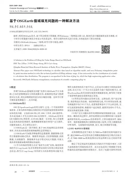
基于OSGEarth值域填充问题的一种解决方法邹韬,李雪,杨东升,华彩成(中国电波传播研究所青岛分所,山东青岛266107)摘要:利用OSGEarth技术,基于算法模型计算数据,利用delaunay三角网逐点插入法,解决任意区域值域填充技术难题,对于科学计算数据可视化分布显示具有普适性。
程序以插件的形式进行封装,具有较高的工程应用价值。
关键词:OSGEarth;Delaunay三角网;科学计算可视化;插件中图分类号:TP311文献标识码:A文章编号:1009-3044(2020)34-0020-03开放科学(资源服务)标识码(OSID):A Solution to the Problem of Filling the Value Range Based on OSGEarthZOU Tao,LIXue,YANG Dong-sheng,HUA Cai-cheng(Qingdao Branchof China Research Institute of Radio Wave Propagation,Qingdao266107,China)Abstract:This paper uses OSGEarth technology to calculate data based on algorithm model,and uses Delaunay triangulation point by point insertion method to solve the technical problem of filling arbitrary range.It has universality for the visualization of scientif⁃ic calculation data distribution.The program is encapsulated in the form of plug-in,which has high engineering application value. Keywords:OSGEarth;Delaunay triangulation;visualization of scientific computing;plug-in1概述所谓“OSGEarth值域填充问题”是指以OSGEarth平台为基础,已知任意物理量在空间的离散分布,依据颜色列表与物理值对应关系,填充该物理量任意分布区域的问题。
收稿日期:2010-1-8作者简介:崔萍(1976~),女,博士,讲师;山东建筑大学热能学院(250101);0531-863637626;E-mail:sdcuiping@ 基金项目:国家自然科学基金项目(No.50946039)竖直地埋管换热器优化设计与模拟软件崔萍1刁乃仁1杨洪兴2方肇洪11山东建筑大学地源热泵研究所2香港理工大学屋宇设备系摘要:本文首先讨论了地源热泵系统竖直埋管地热换热器的理论传热模型及其解析解,然后详细介绍了根据这一模型开发并完善的地热换热器设计和模拟计算软件“地热之星GeoStar V3.0”。
该软件除了根据负荷设计计算地埋管的总长度以外,还可计算系统的热泵能耗、地埋管换热器的换热量、孔壁的温度变化以及其他性能参数。
GeoStar V3.0还增加了设计太阳能辅助地源热泵系统的功能,可对热负荷占优的建筑进行太阳能集热器与地埋管换热器联合运行的优化设计。
本文最后针对某一地源热泵示范工程进行了设计计算。
使用结果表明,软件中采用的理论传热模型和设计计算方法可以较精确地用于指导工程实践与相关的科研项目。
关键词:地源热泵地热换热器设计计算传热Simulation Modeling and Design Optimization of Vertical Ground HeatExchangerCUI Ping 1,DIAO Nai-ren 1,YANG Hong-xing 2,FANG Zhao-hong 11Ground Source Heat Pump Research Center,Shandong Jianzhu University 2Department of Building Services Engineering,The Hong Kong Polytechnic UniversityAbst r act :The paper primarily discusses the analytical heat transfer models for the vertical GHEs and introduces the attendant program named “GeoStar ”developed for use in design and simulation of vertical GHEs.The GeoStar can calculate the required borehole length and predict time-varying heat pump energy consumption,heat transfer rates of GHEs,and other variables of interest during a long-time period of over 20years.Meanwhile,the simulation model for the solar-ground source heat pump systems is developed and incorporated into the program,which can design the solar collector area required for heating-dominated buildings.Finally,the program is used to design an existing GSHP project and to simulate the system performance.The results demonstrate the usefulness of the simulation model and attendant program as a tool for designing the GSHP systems.Keywor ds:ground source heat pump,ground heat exchanger,design,heat transfer0引言竖直埋管地源热泵技术利用可再生的浅层地热能通过热泵机组对建筑物实现供暖,空调及提供生活用热水。

国内外常用道路规划设计软件集合国内常用道路规划设计软件纬地道路辅助设计系统(HintCAD)道路与互通式立交设计的大型专业CAD 软件。
该系统由中交第一公路勘察设计研究院结合多个工程理论研制开发。
纬地系统秉承本院近半个世纪的公路勘察设计经历,汲取国内外专业软件之所长,推陈出新,它是先进的工程设计理念和尖端的计算机软件技术的结晶。
系统具有专业性强,与实际工程设计结合严密、符合国人习惯、实用灵敏等特点。
系统使用BjectARX及Visual C++编程,支持AutoCAD R2000/R2002/R2004/R2005/R2006 平台Windows9X/NT/2000/XP/VISTA等操作系统, 系统主要功能包括:公路道路设计、互通立交设计、三维数字地面模型应用、公路全三维建模〔3DRoad〕等适用于高速、一级、二、三四级公路主线、互通立交、城市道路及平交口的几何设计。
系统同时提供标准版、专业版、数模版和网络版软件,用户可根据不同需求自由选择。
纬地系统利用实时拖动技术,使用户直接在计算机上动态交互式完成公路道路的平(纵、横)设计、绘图、出表;在互通式立交设计方面,系统更以独特的立交曲线设计方法、起终点智能化接线和灵敏批量的连接部处理等功能而著称。
最新的数模版不仅支持国内常规的基于外业测量数据根底上的道路与互通式立交设计,更可以利用三维电子地形图,建立三维数模并直接获得准确的纵、横断地面线数据,进而进展平、纵、横系统化设计;在省去外业测量的人马劳顿和缩短设计周期的同时,更使得大范围的道路方案深度比选方便快捷。
它打破了国内公路行业数模应用领域由国外软件形成的垄断。
海地公路优化设计系统〔Hard〕海地公司倍感荣耀的公路设计软件之一,用户遍布全国30个省、直辖市,近10年来,全国1000多家海地用户应用Hard系统完成数十万公里的公路设计,建立完成的道路遍布祖国大江南北。
Hard系统已经成为国内设计企业在购置软件时的首选,是设计工程师不可缺少的软件工具。

MONGOOSE VT604 GPS-GPRS TRACKEROWNERS MANUALInstallationandM-TRAK ConfigurationM-TRAK is the Mongoose internet web-server which is hosted in New Zealand for fast24/7access.M-TRAK requires no software to install on your computer.M-TRAK can be accessed through any internet ready PC,tablet or smart-phone.You control your vehicles reported locations,therefore the cost.M-TRAK records and preserves the travel history for you to download and produce electronic or printed reports..auHow it worksThe Mongoose VT604is a GPS tracker which uses the GPRS(General Packet Radio System)mobile network to transmit its location‘data’to our M-TRAK web-server located in Auckland,New Zealand.GPRS uses data,not SMS text messages,to send location information from the tracker to the M-TRAK web-server.It also uses GPRS to send commands from the web-server to the tracker.A SIM card with data allowance is required.Most contract cards have a certain amount of data usage Always use a SIM with adequate data for up to10mb per month per vehicle.‘Data/text’contracts are only available from the card providers directly.M-TRAK records the vehicle movement from its last reported‘live’location as well as maintaining a full record of current and previous travel history.This travel history can be searched by date and time,viewed on-screen or printed as a report.There is also the option of saving the location data on your own computer.The VT604is controlled by GPRS commands from the M-TRAK website.SMS text messaging is used for;a)initial setup to instruct the tracker where to send the tracking data.b)to ask its actual current location.An M-TRAK account will be created for you with your own unique username and password.These give you24/7access to the M-TRAK web-server where you can have full control of your vehicle(s)frequency of reporting.You can also view,save and print reports.The M-TRAK programme is self explanatory as it is very similar to other Windows based programmes.The VT604can report locations by either time or distance travelled–or both.To keep costs really low,the VT604was designed to be installed to only report when the engine is running and the vehicle driven.This can be changed if constant24/7reporting is required.When the engine is started,a GPRS session is opened with the mobile provider and when the engine is stopped,the session ends.Most mobile data SIM providers usually only charge per session.The tracker doesn’t transmit its location when the engine is off,so just use the SMS text command if you need to know where it is at any time.Basic functionsFunction DetailsLive Tracking Monitor online vehicles’last LIVE reported location with our M-TRAK web based fleet management server.Or send an SMS to find out where it is right now.Track according to time interval The tracker sends its location to M-TRAK at your selected time intervals from5seconds and above. From within M-TRAK you control and select the time intervals.(30seconds is typical as this gives an accurate map trace)Track according to distance The tracker can send its location to M-TRAK at pre-set distance intervals.From within M-TRAK you control and select the distance intervals.(250~500 metres is typical for an accurate map trace)Geo-fence Detect when a vehicle is driven out or into a pre-defined‘geo-fenced’area.Speeding alert Monitor vehicle’s speed.Send speeding alarm to the M-TRAK server.Mileage Calculate mileage and report by using of GPS speed.SMS tracking Simply send a text to tracker to request current location.Tracker will check the location in Google maps and reply with location address.ALERTSSOS If the driver presses and holds the‘SOS’button in emergency,the GPS tracker will report the emergency to the M-TRAK server and send an SMS to the controller mobile phone.External power cut off report When the GPS tracker’s power supply is cut off,it will report to the M-TRAK server.Immobilise thevehicle If the vehicle is stolen or used without permission, you can immobilise the engine.This is usually the starter motor which prevents the engine being started next time–far safer than simply cutting the engine at any time.COMMUNICATIONDouble reporting The VT604has the ability to send its data to two servers.UDP/TCP Connection Tracker supports both SMS and GPRS (TCP /UDP)communication.Tracker controlThe VT604is controlledby you from the M-TRAK web-server.Set M-TRAK address via mobile phoneYour mobile phone is used to setup the basic parameters such as:-APN,server’s IP address,server port number,controller number and trackersSIM number.POWER MANAGEMENTTracker self test Tracker will test itself to ensure correct operation.If it detects a fault,it will report to the M-TRAK server with a fault description.Power SavingMode While engine off,device automatically switch off GPS and GPRS connection,extend more battery lifeLow Voltage ProtectionWhen vehicle battery voltage is lower than normal,the VT604will switch off so as to avoid further discharge.InstallationNote:This product is for professional installation.Any fault to this product or the vehicle caused by incorrect installation by unauthorised persons voids any warranties.Insert the SIM card and turn on the battery back-up∙Remove back cover and slide open the SIM card holder.∙Insert SIM card into holder,fold down and slide clip into place.∙Turn circled micro switch to ‘on’.(This turns on the battery back-up)∙Re-fit rear coverWiring connections RED -Constant (+)12v fused BLACK -Ground (-neg)YELLOW -Ignition detect (+12v)–sometimes marked ‘ACC’THIN RED -Immobiliser ground out (-),use a relay (not supplied)SOS switch-Pre-wired,mount in a handy but hidden location.Connection to a vehicles car alarm siren (if vehicle equipped)Mongoose alarms have a (+)positive siren e a suitable low impedance miniature relay,not supplied,to convert this positive siren output to negative –fig 1.Connect to pin 1(black)as shown in the diagram below.For (-)negative siren connection;No relay required,connect siren trigger wire to thin black pin 1with a diode in-line to prevent pressing SOS button sounding the siren.Fig11.Thin black –SOS input (-)2.Thin red –SOS output (-)3.Black/red –Ground (-)4.Thin red –no connection5.Green –no connection6.Red -+12v constant (+)7.Thin black –No connection8.Thin red –Immobiliser output (-)9.Yellow –Ignition input (+)‘ACC’Note:SOS alarm feature inoperative from a pulsed horn honk -input must be constant ground for 5seconds or more.GSM antenna –mount above interior mirror for best reception.Dress cable around windscreen and down ‘A’pillar.GPS antenna –mount where it can ‘see’the sky to receive satellite reception.Hide antenna from view and tampering.Under dash above glove box is ideal providing dash is plastic.Antenna cannot ‘see’through metal.OPTIONAL ENGINE IMMOBILISER RELAYThin Red from tracker #88785863087+12VSTARTERCUQuick Start GuideDevice Start-up:1.Insert the SIM card.2.Connect the trackers wiring to the vehicle.3.Install and connect the GSM and GPS antennas.4.Turn on the trackers battery back-up battery.(see photos)5.Mount and secure the GPS module from tampering.6.Turn the ignition‘on’and start the engine to activate the unit.7.Move vehicle outdoors for good GPS reception.8.Check status LED’s for correct operation.See chart below.9.Install and hide the GPS module from access and tampering.GREEN GSM LED DescriptionFlashes onceevery3secondsGSM connected and working LED off No power in or IGN not connected.Flashes onceevery0.2secondsData transmissionLED constant on–not flashing No GSM signal or connection.Check GSMantenna connection.RED GPS LEDFlashes once every1second GPS satellites acquired and working LED off No power in or IGN not connected.LED constant on–not flashing No GPS satellites acquired.Check GPS antenna connection–outdoors.Configure the tracker for M-TRAKJust one SMS text message is all that is required to set-up the VT604.(4U,Controller mobile number,IPaddress,port,APN,,SIM number of tracker) Description:Controller Mobile Number=The phone number of the controlling mobile phone IP address=IP address of the M-TRAK serverport=port number of the M-TRAK serverAPN=‘Access Point Name”-mobile service providersaddressSIM=The SIM card mobile number in tracker Example:(4U,021*******,220048083028,12342332,,,021*******) Include brackets and commas.Tracker will reply"Done!"when completed. SMS commands Default Password as111111.Request Location(where is it right now?)When ignition is on:Command:(AI*RPassword)Sample:(AI*R111111)1st3letters are upper case-include brackets in SMS.The tracker will reply with latitude and longitude with a link to Google maps for Smartphones.When ignition is on or off:Command:(AI*PPassword)Sample:(AI*P111111)1st3letters are upper case-include brackets in SMS.The tracker will reply with location address text message.Change PasswordCommand:(AI*WOld Password*New Password)Sample:(AI*W111111*123456)Controlling the VT604The M-Trak web server is used to control the GPS tracker.This control can be found under‘device parameters’.Select‘add’and a vehicle list will appear.A drop down box shows the various options of control.Please note,some options do not apply to the model VT604.The most common options are highlighted in bold.1.Driver access n/a2.Call restriction n/a3.Speed limit warning set limit for warning4.Time for power saving mode Save power after ignition offDefault30minutes5.Sleep parameters Time to sleep mode withignition on if speed is zero6.Overtime parking Set time limit for parking withignition on before reporting7.Function switch a)Turn off GSM or not underpower save modeb}When speed is zero stillupload GPS data or noteage When to upload data9.Interval to upload time data Set how often to locatevehicle and upload data toserver.Default is30seconds 10.Link to maintain GPRS How long to keep GPRSconnection open whentracker is in sleep mode.Default3minutes.11.Fuel alarm n/a12.Snapshot of parameters n/a13.Wake-up after power save Restart the tracker14.Cancel alarm warning Resets alarm parameters15.Engine lock Immobilise the vehicle,on or off16.Device software version Checks software version17.Check fuel level setting n/a18.RFID n/a19.Temperature threshold n/a20.Interval to upload distance Set how often to locatevehicle by distance travelled.Default is250metres.Set parameters9or20–both can be used but will double the data usage.Technical SpecificationGSM module Huawei GTM900,GSM850/900/1800/1900, Support dual-band or quad-bandGPS Chipset SIRF-Star III chipsetGPS Sensitivity-159dBmGPS Frequency L1,1575.42MHzC/A Code 1.023MHz chip rateChannels20channel all-in-view tracking Position Accuracy10meters,2D RMSVelocity Accuracy0.1m/sTime Accuracy1us synchronized to GPS time Datum WGS-84Reacquisition0.1sec.,averageHot start1sec.,averageWarm start38sec.,averageCold start42sec.,averageAltitude Limit18,000meters(60,000feet)max.Velocity Limit515meters/second(1000knots)max.Acceleration Limit Less than4gJerk Limit20m/secOperating temperature-25℃to70℃Humidity5%to95%Non-condensing Battery Back-up Voltage Rechargeable1300mAh battery(3.7V) Operating Voltage DC12~24V11Mongoose New Zealand Web site: 41A View Road,Glenfield,Auckland PO Box 101-599NSMC Ph:(09)4433128Fax:(09)4433129Email:*****************.nz。

THE TOTAL ALIGNMENT SOLUTIONTME710 / E720E710 / E720Laser shaft alignment systems for all important steps of machine installation.LONG TERM AND RELIABLEEasy-Laser® measurement systemshave been developed from morethan twenty five years experience of solving measurement problems for the industry. Our philosophy is that the products we develop must not only have long operat-ing times but also a long lifecycle. We design FAST SERVICE AND SUPPORTEasy-Laser® measurement systemsare available from local dealersin more than 70 countries, butthere are users to be found in many morecountries.and the best possible support are of greatimportance, and the same is no doubt trueLARGE SAVINGSEasy-Laser® measurement systemsare already extremely flexible intheir standard form. By using cleveraccessories, you can adapt the systems foryour own needs, now and in the future asyour measurement requirements change.It is cost-effective. Your production capacityA foundation has to be flat within 0.1 mm/1000 mm to be able to do itsjob as intended. 0.1 mm is the same as the thickness of a human hair!Laser transmitter D22 included with system E720 will provide maximumpossibilities to set up machines for problem free operation.The lubricating film in a bearing is very thin. A machine poorly aligned,or a foundation not supporting the machine in a proper way, will causeincreased pressure and overheating of the lubricating film. This will inthe end destroy the lubricant, and cause the machine to fail.EASY-LASER® E720 WITH LASER TRANSMITTER D22 Machine set-up most often starts with the foundation. If the foundation is level and flat you will have less problems with the rest of the installation and alignment of the machine. With Easy-Laser® E720 you not only get all the functions and features for the alignment of the machine, but also possibilities to perform the following:• Measure the flatness of the foundation• Check plane parallelism for several surfaces on large machines • Measure flatness for a single machine foot support surface • Align the foundation level and plumb• Align pipes straight and squareThe measuring units included with system E720 uses point laser technology. This is one of the reasons it can be used in so many more places in your operations than just to align the shafts of rotating machinery.Also a standard E710 will provide more measurement and align-ment possibilities than a line laser system can, but the key to true versatility is the D22.SIMPLE AND EFFECTIVE Easy to use = Fast and efficient!Easy-Laser® is used to align generators and gearboxes in Engines, gearboxes and propeller shafts on ships are aligned Easy-Laser® is used to align pumps and motors for allE FTHERMAL GROWTH COMPENSATIONIn many cases, the machines (for example a pump and motor) expand considerably from a cold to a hot state (op-erating temperature). The Thermal Growth Compensation function allows the measure-ment system to calculate the correct shims EASYTURN™ AND MULTIPOINT With the EasyTurn™ function you can start measurement anywhere on the turn. Turn the shafts with the measur-ing units to three positions in any direction with as little as 20° between to register the measurement value. Measurement is complete! For advanced applications, such as turbines, there is a Multipoint function where any number of measuring pointsaround the whole or part of the rotation can be registered.SOFT FOOT CHECK1. Enter the distances between measuring units and the machine feet. If you enter the coupling diameter you can also get the result as gap/sag.2. Take the measurement values in three positions with as little as 20° between. It is clearly visible on the display when the laser beam hits the detector.3. The live values are used to adjust the machine. For clarity the adjustment is displayed both graphi-cally and numerically. Horizontal and Vertical direc-tions are shown at the same time.HORIZONTAL MACHINESHorizontally coupled machines often consist of a pump and motor, but there can also be other types of machine such as a gearboxes and compres-sors. Regardless of what the machine is it is easy to measure and align with Easy-Laser®. Start the alignment work by perform-ing a soft foot check to ensure the machine is resting evenly on all its feet. This is necessary for a reliable align-ment. The program shows which foot (feet) should be corrected. After the soft foot check you can go directly to the alignment program with all of the machine’s distances saved.A. Information field. States what you must do at each stage of the measurement. Also displays Bluetooth® connection, warning symbols etc.B. You can start from a previous measurement and so avoid re-entering the dimensions, the barcode reader is the fastest method.C. The detector surface is shown on the screen and functions as an electronic target for the laser beams.D. 20° marking. The S unit position on the shaft is shown. You can also choose to show the M unit when you align uncoupled machines.E. Shims values for front and rear pairs of feet. Offset and angular values are colour coded in order to deter-mine the result more quickly: red=outside tolerance, green=inside tolerance.F . Horizontal adjustment values. Offset and angular values are colour coded.1.2.3. Finished!20°+20° Min.Multipointfunction (360°)TOLERANCE CHECKMeasurement results can be checked against pre-defined tolerance tables or values you determine yourself. In this way, you can see immediately whether the alignment is within the approved toler-ances. This means the times for alignment are shortened considerably.MEASUREMENT VALUE FILTERAdvanced electronic filter func-tion that can be used for a reli-able measurement result even in a very poor measurement environment, for example where there is air turbulence from open entrances or vibrations from adjacent VERTICAL/FLANGE-MOUNTED MACHINES REFERENCE FOOT LOCKINGThis function allows you to lock any pair of feet on the machine. This gives great freedom when aligning base-bound or bolt-bound machines.MACHINE FEET CONFIGURATIONSThe software can handle machine design of all types: two pairs of feet, three pairs of feet, pair of feet before the coupling etc.LIVE-ANY-ANGLE 360°This function allows adjustment of the machines live with the measuring units positioned anywhere around the shaft. Good for when machine parts prevent normal adjuster positioning.CARDAN/OFFSET-MOUNTED MACHINESMACHINE TRAINSAlignment of vertical and flange-mounted machines. Shows centre offset, angular error and shim value at each bolt.Alignment of cardan/offset mounted machines. (Accessory Cardan fixture, Part No. 12-0615 is required.)Regardless of what machines you have and in which order they were assembled, you can build your own machine train with theoretically as many machines as you like. You can pick the refer-ence machine manually, or let the program choose one that will minimize the need for adjustments.SWAP VIEW FUNCTIONChoose from which side you want to display the machine, so it corresponds to your reality. Simplifies the under-standing of the adjustment directions.QUALITY ASSESSMENTFunction in Multipoint measurement that helps you achieve the best pos-sible result during alignment.This program shows centre offset and angular error between two shafts, for example. The values are displayed for both horizontal and vertical direction simultaneously. Can also be used for dynamic measurements.OFFSET AND ANGLEAll our measurement systems come with the extremely useful Values program. The program can be used e.g. when one wants to measure as with dial gauges and to check bearing play. With the standard equipment and completely normal set up on the machine!MANY OPTIONSMORE GEO WITH E720CHECKING BEARING PLAYWith our program for measuring straightness, you can easily measure long shafts, rolls, bearings, bases, machine structures etc. All you have to do is define a number of measuring points, in advance or while measuring. You will be able to get the result for both the horizontal and vertical alignment, graphically as well as digitally. The D22 Laser trans-mitter included with system E720 will provide even more alignmentpossibilities for you.STRAIGHTNESS MEASUREMENTThe twist measurement program allows you to check the flatness or twist of the machine foundation us-ing only the measuring units in the system.TWIST AND FLATNESS MEASUREMENTFLATNESSThe contact surface for a machine has to be flat within 0.1 mm/1000mm.FLANGE FLATNESSWith this program you can meas-ure sealing surfaces on tanks, heat exchangers and slewing bearings, to mention just a few examples.SQUARENESSLaser transmitter D22 acts as a digital try square.LEVELAll machines has to be placed level or plumb for optimum operation, gener-ally speaking.SHEAVE/PULLEY ALIGNMENTUsing the system you can alignsheaves and pulleys with digital preci-sion. Adjustment of the machines is displayed in real time on the screen, with readings for angle and axial displacement in both the vertical and horizontal axes, as well as an adjustment value for the front or rear foot pair. The result can be documented as normal. (Requires the XT190 BTA accessory.)You can measure vibration levels (mm/s, inch/s) and bearing condition (g-value). The program guides the user through the points to measure on the machine: vertical, horizontal and axial. The result can be documented. (Requires the E285 Vibrometer probe accessory.)DOCUMENTATIONCREATE A PDF REPORT DIRECTLYWhen measurement is complete it is pos-sible to generate a PDF report containing graphs and measurement data directly in the measurement system’s display unit. All the information about the measurement object is documented, and you can add your com-pany’s logo and address details if you so wish.SAVING IN THE BUILT-IN MEMORYYou can, of course, save all measurements in the display unit’s internal memory.SAVE TO USB MEMORYYou can easily save desired measurements on your USB memory. This enables you to take it to your computer to print reports whilst leav-ing the measurement system in place.CONNECT TO YOUR COMPUTERThe display unit is connected to the comput-er via the USB port. It then appears on the desktop as a USB Mass Storage Device which you can easily transfer files to and from.EASYLINK™ PC SOFTWAREWith the EasyLink™ database program you can save and organise all your measurements in one place, produce reports with both data and images and export to your maintenance systems. You can customise what your Excel reports should look like and what data should be visible and where it should be positioned. The program has a clear folder structure, where you drag and drop files from the display unit to the database. Create your own structure with folders for manufacturer, department or machine type for example. The database can also be located on a com-mon server and shared with other users. For extra safety you can use EasyLink™ to make backups of what you have saved in the display unit.BARCODE READERThe barcode reader is used to enter the machine data before measurement is taken. After the first measurement is recorded, the adhesive barcode label is applied to the machine. Next time the machine is checked, the measurements, compensation values and tolerances can be read directly from the barcode. Simple and accurate! (Accessory.)VIBRATION MEASUREMENT AND BEARING CONDITION3BAC DEA B C DH I J G F KE 4DISPLAY UNITThe display unit enables you to work more efficiently and for longer than ever before. It has wireless technology and integrated rechargeable battery.NEVER LOSE POWER!The display unit is equipped with ourEndurio™ Power management system. This ensures that you never have to stop in the A. Laser aperture B. Swivelling head C. Laser aperture D. Leveling screws (x2)E. Magnetic feet (x3)A. Two Enter buttons, for left and right- handed usersB. Large, easy to read colour displayC. P roper buttons for clear feedbackD. Thin profile gives a perfect grip for your handsE. Battery compartmentF. Robust, rubber coated designG. C onnection for chargerH. U SB AA CDBEF GA. The rods have a height of 60–180 mm. Ifnecessary they can be extended ”infinitely” withadditional rods. Made of stainless steel.B. Well protected connectorsC. PSD (2 axis)D. Laser apertureSTANDARD BRACKETS INCLUDED IN SYSTEM E710 AND E720THE TOTAL TMALIGNMENTSOLUTIONSystem E720 pictured.。
目录第一章序言 (1)第一节GeoMedia概述 (1)第二节GeoMedia使用须知 (2)第三节GeoMedia起步 (4)第四节进出GeoMedia (5)第五节GeoMedia工作流程 (6)第二章工作区的使用 (7)第一节工作区概述 (7)第二节工作区的创建 (7)第三节寻找你所要的工作区 (8)第四节保存、关闭和拷贝一个工作区 (9)第五节Email工作区 (9)第六节创建工作区模板 (9)第三章坐标系统的使用 (10)第一节定义工作区的坐标系统 (10)第二节坐标的读出 (12)第三节坐标参数设置 (12)第四节测量参数设置 (13)第五节Datum交换设定 (14)第六节无坐标系统的数据显示 (15)第四章数据库的使用 (17)第一节创建可读/写数据库 (17)第二节为数据库定义坐标系统。
(19)第五章地图窗的使用 (20)第一节步骤 (20)第二节方法 (21)第三节例子 (25)第六章使用数据窗口 (30)第一节打开数据窗口 (30)第二节控制数据窗口 (30)第三节使用数据视图工具 (30)第四节在数据窗中使用鼠标 (31)第五节编辑数据窗口中单元格 (31)第六节数据窗口快照 (32)第七章使用要素 (33)第一节解释几何类型 (33)第二节要素选择 (33)第三节使用要素类 (35)第四节在要素类中插入文本要素 (36)第五节给要素类添加要素 (37)第六节添加几何 (38)第七节给数据窗插入超级文本 (38)第八节改变要素的属性值 (39)第九节在要素周围放置缓冲区 (39)第十节改变和删除要素 (41)第八章使用查询 (42)第一节在GeoMedia中建立查询 (42)第二节定义空间查询 (44)第三节显示查询 (45)第四节编辑查询 (45)第五节删除查询 (46)第九章使用标签 (48)第一节建立标签 (48)第二节把CAD图形链接到数据库属性 (48)第十章输出GeoMedia数据 (50)第一节打印当前窗口 (50)第二节使用Imagination Engineer来显示和打印地图 (53)第三节建立地图视图 (54)第四节设计地图版面 (55)附录A:怎样与Intergraph联系 (58)附录B:GDOO信息 (61)第一章序言欢迎使用新一代地理信息系统软件GeoMedia。
Unit1 What is Geomatics ?Geomatics :Where does the word Geomatics come from? GEODESY +GEOINFORMATICS = GEOMATICS or GEO— for earth and -MATICS for mathematical or GEO- for Geoscience and —MATICS for informatics .Now the term includes the traditional surveying definition along with surveying steadily increased importance with the development of new technologies and the growing demand for a variety of spatially related types of information,particularly in measuring and monitoring our environment . Geomatics bridges wide arcs from the geosciences through various engineering sciences and computer sciences to spatial planning,land development and the environmental sciences .ISO:the International Standards Organization (ISO)surveyor :The term “surveyor" is traditionally used to collectively describe those engaged in the above activities 。
ENVI使⽤举例ENVI中利⽤⽮量边界裁剪栅格数据详解 (2)打开影像⽂件和⽮量⽂件叠加在⼀起显⽰ (3)ENVI⼏何校正的步骤 (3)ENVI解译例⼦ (4)⼀. 界⾯系统介绍 (4)⼆. ⽂件的存取与显⽰ (4)三. 图像预处理 (5)四. 影像分析 (6)五.图像增强(Image:Enhance) (6)六.专题信息提取 (7)七. 制图输出 (10)⼟地利⽤/覆盖变化信息提取实验报告 (11)1. 实验⽬的 (11)2. 实验内容 (11)3. 实验⽅案 (12)4. 数据预处理 (12)4.1 数据源 (12)4.2 图像预处理 (12)5 ⼟地利⽤/⼟地覆被分类 (14)5.1 监督分类法 (14)5.2 决策树分类 (16)5.3 两种分类精度评定及结果分析 (19)6 ⼟地利⽤/覆被变化分析 (20)6.1 ⾦华市⼟地利⽤类型的数量变化 (20)6.2 ⾦华市⼟地利⽤类型转换变化 (20)影像信息提取(⼀、⽬视解译) (22)影像信息提取(⼆、监督与⾮监督分类) (28)影像信息提取(三、基于专家知识的决策树分类) (46)影像信息提取(四、⾯向对象特征提取) (55)影像信息提取(五、多时相影像动态检测技术) (73)总结 (81)ENVI中利⽤⽮量边界裁剪栅格数据详解以前在论坛和群⾥⾯看到过很多⼈问如何在ENVI中利⽤不规则边界来裁剪栅格影像,都只是告诉他们将⽮量数据转为ROI然后再Subset就可以。
今天⼜碰到了,就将在ENVI中裁剪栅格的步骤写下来,以⽅便参考:注:此处⽤到的数据是群⾥⼀位朋友的,在此作为⼀个例⼦来说明如何裁剪数据。
数据:⽮量数据为SHP格式,⾯状(多边形)特征⽂件 test.tif。
栅格数据为TIFF 格式 testshp.shp 。
1、打开栅格数据:通过 File -- Open Image或者 File -- Open External File -- Generic Formats -- TIFF/GeoTIFF2、打开⽮量数据:通过 File -- Open Vector或者 Vector -- Open Vector,选择⽂件类型Shapefile(*.shp) ,选择⽮量⽂件 testshp.shp,注意在弹出的Import Vector Files Parameters 对话框选择正确的投影类型。
geogebra计算方差英文回答:To calculate variance in GeoGebra, you can use the built-in statistical functions. Here's how you can do it:1. First, enter your data into a column in the spreadsheet view. Let's say you have a set of numbers in column A, starting from cell A1.2. To calculate the variance, you can use the "Var" function. In a new cell, let's say B1, enter the formula "=Var(A1:A)" and press Enter. This formula calculates the variance of the data in column A.3. The result will be displayed in cell B1. It represents the variance of the data set.For example, let's say you have the following numbers in column A: 1, 2, 3, 4, 5. To calculate the variance, youwould enter the formula "=Var(A1:A)" in cell B1. The result would be 2.5, which is the variance of the data set.GeoGebra also provides other statistical functions that you can use to calculate measures of dispersion, such as standard deviation. You can explore these functions in the spreadsheet view by typing "=" followed by the function name and the range of data.中文回答:在 GeoGebra 中计算方差,你可以使用内置的统计函数。