附录1 外文翻译
基于事例推理的夹具设计研究与应用
摘要:根据基于事例的设计方法,提出采用工序件的特征信息和夹具的结构特征信息来描述夹具的相似性,并建立了包括这2方面主要特征信息为基础的事例索引码,设计了事例库的结构形式,创建了层次化的事例组织方式;同时,提出了基于知识引导的夹具事例检索算法,以及事例的修改和采用同族事例码进行相似事例的存贮,形成了基于事例推理的夹具设计.所开发的原型系统在型号工程夹具设计等项目的设计过程中得到了应用,并取得了令人满意的使用效果.
关键词: 基于事例的推理夹具设计CAD
夹具是以确定工件安全定位准确为目的的装置,并在加工过程中保持工件与刀具或机床的位置一致不变。因为夹具的结构依赖于产品的特点和在企业规划中加工工序的地位,所以它的设计是制造过程中的瓶颈,制约着效率的提高. 夹具设计是一个复杂的过程,需要有从大量的设计论文中了解质量知识的经验,这些设计论文包括工件的结构设计、涉及加工工艺,和加工环境。当用这些擅长绘制详细设计图的传统的CAD工具(如Unigraphics、CATIA、Pro/E)时,这仍然是一项非常耗时的工作,但是利用以往的设计经验和资源也不能提供一些益处,而这正是提高效率的关键因素. 基于事例推理(CBR) 的方法适应以往个案解决的办法,建立一个新问题的方法,主要有以下四步骤:检索、利用、修改,并保留.这是一个比用专业系统模仿人类思维有用的使用方法,因为提出一个类似的情况,和采用一些修改,似乎不言自明,而且比人类更直观.所以支持不同事例的设计工具已经在诸多领域中发展起来,如在注射成型及设计、建筑设计、模具设计投死, 规划过程中,还有夹具设计. 孙用六个数字组成代码参数,包括工件的形状、机械部分、轴衬,第一定位装置,第二定位装置和夹紧装置. 但这个系统不能用于除钻床夹具外的其他夹具类型,不能解决储存需要保留的同一参数代码的问题,这在CBR中是非常重要的.
1事例参数和事例图书馆的建立
1.1事例参数
事例参数应该由工件的所有的特征组成,来区别不同的夹具. 使用他们能够使操作方便. 因为零件的形状是多种多样的, 在生产企业中制造的技术要求
也不断发展,许多特征作被用做事例参数将会使搜索速度降低,其主要特征是不重要的,因为分配给每个特征的比重必须减少. 另一方面,事例参数包含所有的特征是困难的。
因此,考虑到实际和快速设计的需求,事例参数要包含工件的主要特征和夹具的结构。事例参数代码由16位数组成:13位数是事例特征3位数是事例识别数字。
前13位数代表13个特征。每个数字与特征的一个属性相一致,这可能是"*"、"?"、"1"、"2",…,"A"、"B",…,"Z",…,等其中的一个。其中,"*"是指任何一个,"?"代表不确定,"0"代表没有。
系统规定:夹具的类型,工件的形状,位置模式不能是"*"和"?"。在设计系统时,三个项目的属性信息没有这些选择,这就意味着必须选择确定的属性。
最后三位数是事例识别号码,如果事例特征的13位数是一样的,这三个数字就用来区别他们。
该系统还规定:"000"是用于修正的一个典型事例,其他事例"001"、"002"、…,这些是用于设计师查找参考事例的. 如果其中一个偶尔需要改变成典型事例,首先它必须要求改成"000",前面的自动变成参考事例.
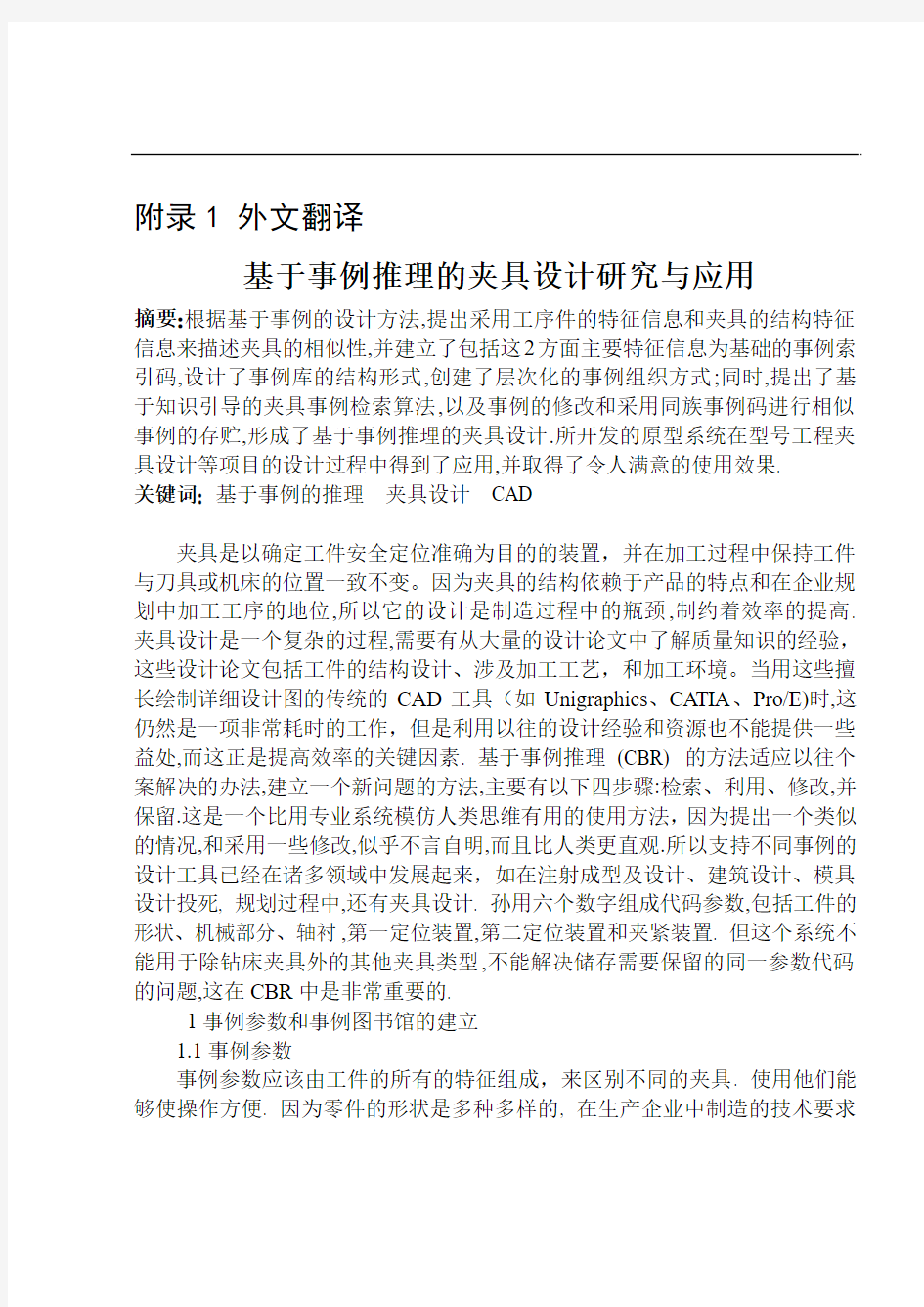
事例索引码的结构如图1所示。
1—夹具类型;6—工件重量;11—夹紧模型;
2—工件形状;7—工件刚度;12—夹具体;
3—工件材料;8—加工内容;13—其他;
4—批量;9—过程所有物;14到16—事例识别码;
5—工件比例;10—定位模型;
图1 事例索引码的结构
1.2事例库
事例库由许多预定义的事例组成。事例的描述是基于事例推理的最重要的问题之一。所以由索引码复合。
1.3 事例的层次化
夹具的结构相似被认为是整个夹具,成分和内容相似。所以,整个夹具事例库,成分事例库,夹具的成分事例库形成相同。整个夹具的设计资料通常是由工件资料和工件加工资料组成,这就意味着夹具的设计应满足特别功能的需
求.全部夹具事例是由功能成分组成,它是用功能成分的名字和数字来进行描述的。成分事例代表成员(成分功能和其他结构成分,主要驱动参数,数字,和它们的约束关系)。成分事例(夹具的最低层)是功能成分和和其他成分的结构。在现代夹具设计中有很多参数化准件和普通非标准件。所以成分事例图书馆应记录特殊参数和保持它们的方法。
2事例修改的策略
在基于事例的夹具设计中,最重要的是相似点的修改,这样能有助于获得最相似的事例,以及缩短适应时间。根据夹具设计的需求,事例修改的策略使最接近的事例方法和知识指导结合起来。首先在深度上查找,然后在宽度上;知识指导策略意味着在来自客观事物根源的知识规则上查找,这就要首先查找固定类型,然后查找工件的形状,第三查找定位方法。例如,如果事例索引码包括夹具类型的磨削夹具,就只查找所有的磨削夹具,然后查找工件形状的盒子,第三查找一个平面两个销的定位方法。如果没有合适的,就查找深度标点,然后回到最上层,然后再找所有与宽度相关的事例。
修改方法:
1)根据夹具事例库的事例索引信息,查找有关事例库。
2)将事例索引码与事例库的每个事例码匹配,然后计算相似尺寸的价值。
3)整理相似尺寸的次序,最大的架子是最类似的事例。
两个事例之间的相似点是基于两个事例特征之间的相似点。相似点尺寸的计算依靠特征的类型。相似点的价值可以通过数字化的价值来计算,例如比较重量分别是50kg 和20kg的工件。非数字化的价值也能计算,例如,现在前13位索引码都是非数字化的价值。一个夹具的相似尺寸的计算公式如下:
其中S表示通用夹具的相似尺寸,n表示索引特性数,表示每个特性的重量,
表示事例库中特性和相关夹具的特性的相似尺寸。同时,
,数值计算如下:
其中表示第i个特征的索引特性值,表示事例库中第j个事例的第i个特
征的特性值。
所以有两种方法选择相似夹具。一个方法是建立数值。如果通用事例的相似尺寸值比给定的数值小,这些事例就不能选来作相似事例。事例库最初建立的时候,只有一些事例,数值可以建小一点。如果有大量的相似事例,数值就应该建的大一些。另外一个方法是只建立相似事例的数字(例如10),这是类型单里相似尺寸的最大值。
3 事例的修改和存储
3.1事例的修改
夹具设计中相似事例的修改包括以下三个阶段:
1)成分的替代
2)保持形式不变,调整成分的特性
3)模型重新设计
如果夹具的成分是普通的物品,它们能通过使用工具被修改,代替以及删除,这些已经被设计好了。
3.2事例的存储
在将一个新的事例保存到事例库之前,设计者必须考虑保存是否有价值。如果这个事例不能增加系统的知识,就没有必要把它保存到事例库里。如果它有价值的话,设计者在保存之前必须分析一下,看看这个事例是否作为标准事例或参考事例被存储了。一个标准事例是一个描述同族事例主要特征的标准。一个同族事例是有事例库中索引码前13位相同而最后三位不同的那些事例组成的。一个标准事例的最后三位通常是“000”。一个参考事例属于同族标准事例,
最后三位用不同数字区分。
从被解释的概念中,可采用以下方法:
1)如果一个新的事例和任何一个存在的事例族一致,和一个存在的标准事例的前13位数相同,那么这个事例就不能存储因为已经这种标准事例了。或者只能作为一个参考事例保存(最后三位不是“000”,而且和其它的不一样)在事例库中。
2)如果一个新的事例和任何一个存在的事例族一致,并且被认为代替这个事例族要比以前的标准事例好,那么这个标准事例就被这个新的事例代替,以前的标准事例作为一个参考事例保存。
3)如果一个新的事例和任何一个存在的事例族不一致,一个新的事例族将会自动产生,并作为标准事例保存到事例库中。
4夹具设计中基于事例推理的过程
根据夹具设计的特性,夹具设计的基本信息,例如夹具的名字,零件,生产和设计者等等,必须先输入。然后,输入或设计工件的模型。输入有关工件的细节信息,建立事例索引码,然后CBR开始依靠相似尺寸查找相似事例,选出最相似的事例。如果需要的话,事例要满足通用性设计,再存储到事例库中。程序流程图如图2所示
图2 基于事例推理的夹具设计流程图
5基于事例推理的夹具设计说明
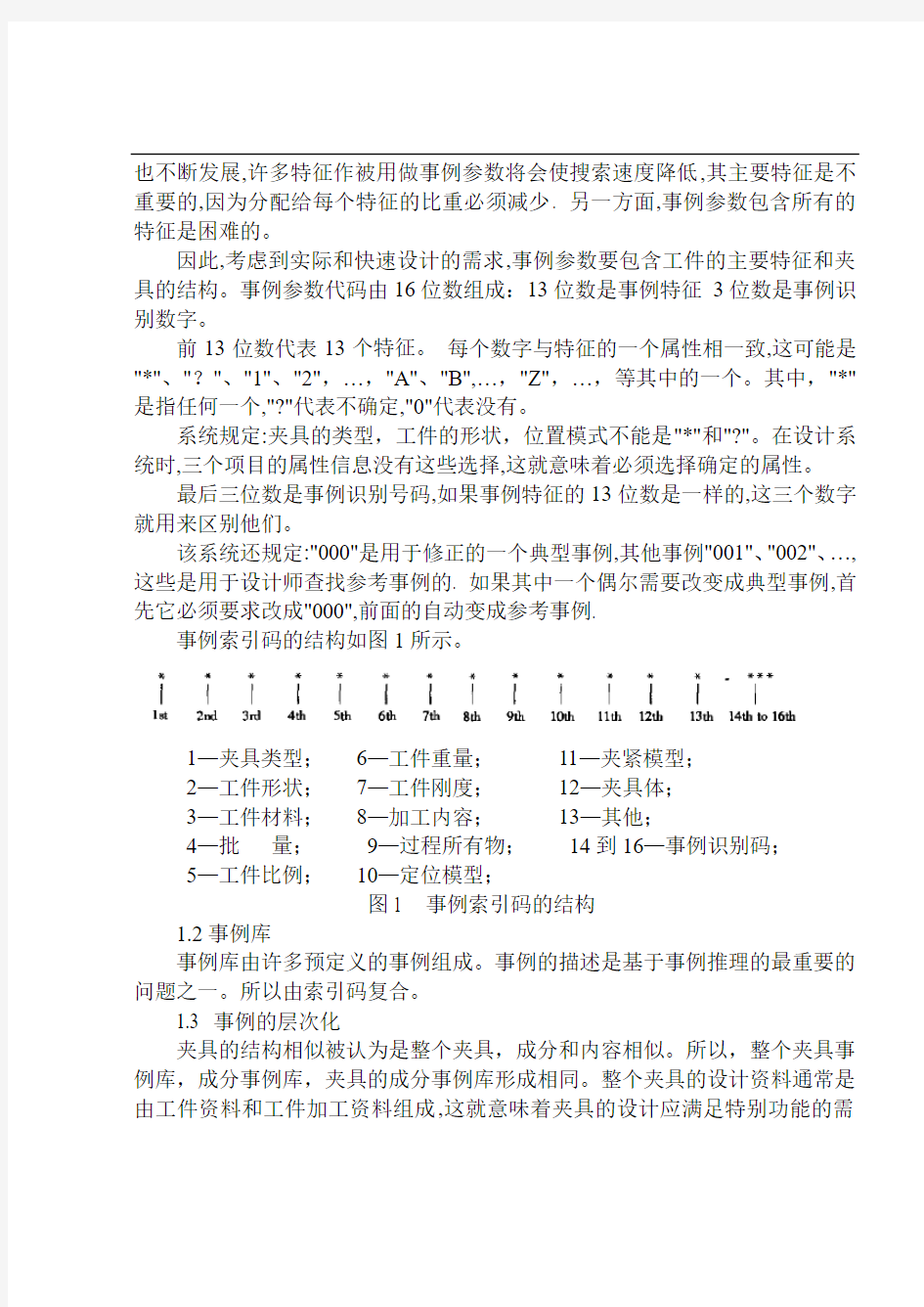
这是一个工件如图3所示。材料是45钢,底座,形状为块状,生产批量为中批等。需要设计成一个用来旋转孔的旋转夹具。
图3 需要设计夹具的一个工件
(最大尺寸80mmx49mmx22mm)
工件的特征值,属性值,事例索引码和重量在表1中列出。
表1 工件的事例索引码和重量
特征名称特性值索引码重量
夹具类型车床夹具 1 100
工件形状块状9 90
工件材料中碳钢 3 70
批量中批 2 60
工件比例小 5 60
工件重量轻 5 60
工件刚度硬度强 1 60
加工内容孔 3 80
程序要求完成加工 3 70
定位方法三个平面 1 100
夹紧方法不确定?90
夹具体复合 4 80
其他没有0 60
通过查找和计算相似点,最相似的事例的事例索引码是19325513321402000,细节信息在表2中列出。
表2 最相似事例的事例索引码
特征名称特性值索引码
夹具类型车床夹具 1
工件形状块状9
工件材料中碳钢 3
批量中批 2
工件比例小 5
工件重量轻 5
工件刚度硬度强 1
加工内容孔 3
程序要求完成加工 3
定位方法三个平面 1
夹紧方法不确定?
夹具体复合 4
其他没有0
相似点的计算如下:
所以夹具的相似尺寸值是0.806,这是在事例库中用于设计的最相似的事例,最相似的事例的结构如图4所示
图4 最相似的夹具
当成分替代,修改定位模型和夹紧模型,以及调节相关尺寸之后,新的夹具被设计出来,图形如图6所示
图5 需要设计的新夹具
因为在事例库中没有相似夹具,新夹具被储存到事例库中。事例索引码是19325523311402000。
6 结论
基于事例推理,作为一个问题解决的方法,是一个比模仿人类思想的专业系统更有效的方法,已经在很多难获取知识的领域里得到发展。基于事例推理的优点如下:它和人类的思想很相似;一个事例库通过保存新事例获得自学能力,它比有惯例库更快更容易,它可以更好的传递和解释新的知识,这和惯例库有
外文资料 The aggregate machine-tool CAD system development and research Abstract aggregate machine-tool CAD is in Window 95/98, Wndows under the NT4.0 environment, designs personnel's special-purpose CAD system with VC5.0 and the AutoCAD R14 ADS/ARX technology development face the aggregate machine-tool.This software technological advance, performance reliable, function strong, convenient practical, has provided the modernized design tool for our country aggregate machine-tool profession. Key word: Aggregate machine-tool CAD jig CAD multi-axle-box CAD 1 uses the aggregate machine-tool CAD technology imperative The aggregate machine-tool is with according to serialized, the standardized design general part and the special purpose machine which composes according to the work piece shape and the processing technological requirement design special-purpose part, belongs to the disposable design, the disposable manufacture piecework product.Therefore, the design quantity is big, the design work is complex.In the
附录A Lathe fixture design and analysis Ma Feiyue (School of Mechanical Engineering, Hefei, Anhui Hefei 230022, China) Abstract: From the start the main types of lathe fixture, fixture on the flower disc and angle iron clamp lathe was introduced, and on the basis of analysis of a lathe fixture design points. Keywords: lathe fixture; design; points Lathe for machining parts on the rotating surface, such as the outer cylinder, inner cylinder and so on. Parts in the processing, the fixture can be installed in the lathe with rotary machine with main primary uranium movement. However, in order to expand the use of lathe, the work piece can also be installed in the lathe of the pallet, tool mounted on the spindle. THE MAIN TYPES OF LATHE FIXTURE Installed on the lathe spindle on the lathe fixture
The Aggregate Machine-tool The Aggregate Machine-tool is based on the workpiece needs, based on a large number of common components, combined with a semi-automatic or automatic machine with a small number of dedicated special components and process according to the workpiece shape and design of special parts and fixtures, composed. Combination machine is generally a combination of the base, slide, fixture, power boxes, multi-axle, tools, etc. From. Combination machine has the following advantages: (1) is mainly used for prism parts and other miscellaneous pieces of perforated surface processing. (2) high productivity. Because the process of concentration, can be multi-faceted, multi-site, multi-axis, multi-tool simultaneous machining. (3) precision and stability. Because the process is fixed, the choice of a mature generic parts, precision fixtures and automatic working cycle to ensure consistent processing accuracy. (4) the development cycle is short, easy to design, manufacture and maintenance, and low cost. Because GM, serialization, high degree of standardization, common parts can be pre-manufactured or mass organizations outsourcing. (5) a high degree of automation, low labor intensity. (6) flexible configuration. Because the structure is a cross-piece, combination. In accordance with the workpiece or process requirements, with plenty of common parts and a few special components consisting of various types of flexible combination of machine tools and automatic lines; tools to facilitate modification: the product or process changes, the general also common components can be reused. Combination of box-type drilling generally used for processing or special shape parts. During machining, the workpiece is generally not rotate, the rotational motion of the tool relative to the workpiece and tool feed movement to achieve drilling, reaming, countersinking, reaming, boring and other processing. Some combination of turning head clamp the workpiece using the machine to make the rotation, the tool for the feed motion, but also on some of the rotating parts (such as the flywheel, the automobile axle shaft, etc.) of cylindrical and face processing. Generally use a combination of multi-axis machine tools, multi-tool, multi-process, multi-faceted or multi-station machining methods simultaneously, productivity increased many times more than generic tools. Since the common components have been standardized and serialized, so can be flexibly configured according to need, you can shorten the design and manufacturing cycle. Multi-axle combination is the core components of general machine tools. It is the choice of generic parts, is designed according to special requirements, in combination machine design process, is one component of a larger workload. It is based on the number and location of the machining process diagram and schematic design combination machine workpiece determined by the hole, cutting the amount of power transmission components and the design of each spindle spindle type movement. Multi-axle power from a common power box, together with the power box installed on the feed slide, to be completed by drilling, reaming and other machining processes. The parts to be processed according to the size of multi-axle box combination machine tool design, based on an original drawing multi-axle diagram, determine the range of design data,
毕业设计 外文翻译 题目曲轴的加工工艺及夹具设计学院航海学院 专业轮机工程 学生佟宝诚 学号 10960123 指导教师彭中波 重庆交通大学 2014年
Proceedings of IMECE2008 2008 ASME International Mechanical Engineering Congress and Exposition October 31-November 6, 2008, Boston, Massachusetts, USA IMECE2008-67447 MULTI-OBJECTIVE SYSTEM OPTIMIZATION OF ENGINE CRANKSHAFTS USING AN INTEGRATION APPROACH Albert Albers/IPEK Institute of Product Development University of Karlsruhe Germany Noel Leon/CIDyT Center for Innovation andDesign Monterrey Institute of Technology,Mexico Humberto Aguayo/CIDyT Center forInnovation and Design, Monterrey Institute ofTechnology, Mexico Thomas Maier/IPEK Institute of Product Development University of Karlsruhe Germany ABSTRACT The ever increasing computer capabilities allow faster analysis in the field of Computer Aided Design and Engineering (CAD & CAE). CAD and CAE systems are currently used in Parametric and Structural Optimization to find optimal topologies and shapes of given parts under certain conditions. This paper describes a general strategy to optimize the balance of a crankshaft, using CAD and CAE software integrated with Genetic Algorithms (GAs) via programming in Java. An introduction to the groundings of this strategy is made among different tools used for its implementation. The analyzed crankshaft is modeled in commercial parametric 3D CAD software. CAD is used for evaluating the fitness function (the balance) and to make geometric modifications. CAE is used for evaluating dynamic restrictions (the eigenfrequencies). A Java interface is programmed to link the CAD model to the CAE software and to the genetic algorithms. In order to make geometry modifications to
Int J Adv Manuf Technol (2006) 29: 178–183 DOI 10.1007/s00170-004-2493-9
ORIGINAL ARTICLE
Ferda C. C ? etinkaya
Unit sized transfer batch scheduling in an automated two-machine ?ow-line cell with one transport agent
Received: 26 July 2004 / Accepted: 22 November 2004 / Published online: 16 November 2005 ? Springer-Verlag London Limited 2005 Abstract The process of splitting a job lot comprised of several identical units into transfer batches (some portion of the lot), and permitting the transfer of processed transfer batches to downstream machines, allows the operations of a job lot to be overlapped. The essence of this idea is to increase the movement of work in the manufacturing environment. In this paper, the scheduling of multiple job lots with unit sized transfer batches is studied for a two-machine ?ow-line cell in which a single transport agent picks a completed unit from the ?rst machine, delivers it to the second machine, and returns to the ?rst machine. A completed unit on the ?rst machine blocks the machine if the transport agent is in transit. We examine this problem for both unit dependent and independent setups on each machine, and propose an optimal solution procedure similar to Johnson’s rule for solving the basic two-machine ?owshop scheduling problem. Keywords Automated guided vehicle · Lot streaming · Scheduling · Sequencing · Transfer batches entire lot to ?nish its processing on the current machine, while downstream machines may be idle. It should be obvious that processing the entire lot as a single object can lead to large workin-process inventories between the machines, and to an increase in the maximum completion time (makespan), which is the total elapsed time to complete the processing of all job lots. However, the splitting of an entire lot into transfer batches to be moved to downstream machines permits the overlapping of different operations on the same product while work proceeds, to complete the lot on the upstream machine. There are many ways to split a lot: transfer batches may be equal or unequal, with the number of splits ranging from one to the number of units in the job lot. For instance, consider a job lot consisting of 100 identical items to be processed in a three-stage manufacturing environment in which the ?ow of its operations is unidirectional from stage 1 through stage 3. Assume that the unit processing time at stages 1, 2, and 3 are 1, 3, 2 min, respectively. If we do not allow transfer batches, the throughput time is (100)(1+3+2) = 600 min (see Fig. 1a). However, if we create two equal sized transfer batches through all stages, the throughput time decreases to 450 min, a reduction of 25% (see Fig. 1b). It is clear that the throughput time decreases as the number of transfer batches increases. Flowshop problems have been studied extensively and reported in the literature without explicitly considering transfer batches. Johnson [1], in his pioneering work, proposed a polynomial time algorithm for determining the optimal makespan when several jobs are processed on a two-machine (two-stage) ?owshop with unlimited buffer. With three or more machines, the problem has been proven to be NP-hard (Garey et al. [2]). Besides the extension of this problem to the m -stage ?owshop problem, optimal solutions to some variations of the basic two-stage problem have been suggested. Mitten [3] considered arbitrary time lags, and optimal scheduling with setup times separated from processing was developed by Yoshida and Hitomi [4]. Separation of the setup, processing and removal times for each job on each machine was considered by Sule and Huang [5]. On the other hand, ?owshop scheduling problems with transfer batches have been examined by various researchers. Vickson
1 Introduction
Most classical shop scheduling models disregard the fact that products are often produced in lots, each lot (process batch) consisting of identical parts (items) to be produced. The size of a job lot (i.e., the number of items it consists of) typically ranges from a few items to several hundred. In any case, job lots are assumed to be indivisible single entities, although an entire job lot consists of many identical items. That is, partial transfer of completed items in a lot between machines on the processing routing of the job lot is impossible. But it is quite unreasonable to wait for the
F.C. ?etinkaya (u) Department of Industrial Engineering, Eastern Mediterranean University, Gazimagusa-T.R.N.C., Mersin Turkey E-mail: ferda.cetinkaya@https://www.doczj.com/doc/8f5180590.html,.tr Tel.: +90-392-6301052 Fax: +90-392-3654029
2604130359 CNC Cutting Technology Review Numerical control high speed cutting technology (High Speed Machining, HSM, or High Speed Cutting, HSC), is one of the advanced manufacturing technology to improve the machining efficiency and quality, the study of related technology has become an important research direction of advanced manufacturing technology at home and abroad. China is a big manufacturing country, in the world of industry transfer to accept the front instead of back-end of the transfer, to master the core technology of advanced manufacturing, or in a new round of international industrial structure adjustment, our country manufacturing industry will further behind. Imminent research on the theory and application of advanced technology. 1, high-speed CNC machining meaning High speed cutting theory put forward by the German physicist Carl.J.Salomon in the last century and early thirty's. He concluded by a lot of experiments: in the normal range of cutting speed, cutting speed if the increase, will cause the cutting temperature rise, exacerbating the wear of cutting tool; however, when the cutting speed is increased to a certain value, as long as more than the inflection point, with the increase of the cutting speed, cutting temperature can not rise, but will decline, so as long as the cutting speed is high enough, it can be solved very well in high cutting temperature caused by tool wear is not conducive to the cutting problem, obtained good processing efficiency. With the development of manufacturing industry, this theory is gradually paid more attention to, and attracted a lot of attention, on the basis of this theory has gradually formed the field of high-speed cutting technology of NC, relatively early research on NC High-speed Machining Technology in developed countries, through the theoretical basis of the research, basic research and applied research and development application, at present applications have entered the substantive stage in some areas. The high-speed cutting processing category, generally have the following several kinds of classification methods, one is to see that cutting speed, cutting speed over conventional cutting speed is 5-10 times of high speed cutting. Also has the scholar to spindle speed as the definition of high-speed processing standards, that the spindle speed is higher than that of 8000r\/min for high speed machining. And from the machine tool spindle design point of view, with the product of DN diameter of spindle and spindle speed, if the value of DN to (5~2000) * 105mm.r\/min, is considered to be of high speed machining. In practice, different processing methods, different materials, high speed cutting speed corresponding to different. Is generally believed that the turning speed of (700~7000) m\/min, milling speed reaches m\/min (300~6000), that is in the high-speed cutting. In addition, from the practical considerations, high-speed machining concept not only contains the high speed cutting process, integration and optimization also contains the process of cutting, is a
TRANSFER AND UNIT MACHINE While the specific intention and application for transfer and unit machine vary from one machine type to another, all forms of transfer and unit machine have common benefits. Here are but a few of the more important benefits offered by TRANSFER AND UNIT MACHINE equipment. The first benefit offered by all forms of transfer and unit machine is improved automation. The operator intervention related to producing workpieces can be reduced or eliminated. Many transfer and unit machine can run unattended during their entire machining cycle, freeing the operator to do other tasks. This gives the transfer and unit machine user several side benefits including reduced operator fatigue, fewer mistakes caused by human error, and consistent and predictable machining time for each workpiece. Since the machine will be running under program control, the skill level required of the transfer and unit machine operator (related to basic machining practice) is also reduced as compared to a machinist producing workpieces with conventional machine tools. The second major benefit of transfer and unit machine technology is consistent and accurate workpieces. Today's transfer and unit machines boast almost unbelievable accuracy and repeatability specifications. This means that once a program is verified, two, ten, or one thousand identical workpieces can be easily produced with precision and consistency. rd benefit offered by most forms of transfer and unit machine tools is flexibility. Since these machines are run from programs, running a different workpiece is almost as easy as loading a different program. Once a program has been verified and executed for one production run, it can be easily recalled the next time the workpiece is to be run. This leads to yet another benefit, fast change over. Since these machines are very easy to set up and run, and since programs can be easily loaded, they allow very short setup time. This is imperative with today's just-in-time (JIT) product requirements.
A review and analysis of current computer-aided fixture design approaches Iain Boyle, Yiming Rong, David C. Brown Keywords: Computer-aided fixture design Fixture design Fixture planning Fixture verification Setup planning Unit design ABSTRACT A key characteristic of the modern market place is the consumer demand for variety. To respond effectively to this demand, manufacturers need to ensure that their manufacturing practices are sufficiently flexible to allow them to achieve rapid product development. Fixturing, which involves using fixtures to secure work pieces during machining so that they can be transformed into parts that meet required design specifications, is a significant contributing factor towards achieving manufacturing flexibility. To enable flexible fixturing, considerable levels of research effort have been devoted to supporting the process of fixture design through the development of computer-aided fixture design (CAFD) tools and approaches. This paper contains a review of these research efforts. Over seventy-five CAFD tools and approaches are reviewed in terms of the fixture design phases they support and the underlying technology upon which they are based. The primary conclusion of the review is that while significant advances have been made in supporting fixture design, there are primarily two research issues that require further effort. The first of these is that current CAFD research is segmented in nature and there remains a need to provide more cohesive fixture design support. Secondly, a greater focus is required on supporting the detailed design of a fixture’s physical structure. 2010 Elsevier Ltd. All rights reserved. Contents 1. Introduction (2) 2. Fixture design (2) 3. Current CAFD approaches (4) 3.1 Setup planning (4) 3.1.1 Approaches to setup planning (4) 3.2 Fixture planning (4) 3.2.1 Approaches to defining the fixturing requirement (6) 3.2.2 Approaches to non-optimized layout planning (6) 3.2.3 Approaches to layout planning optimization (6) 3.3 Unit design (7) 3.3.1 Approaches to conceptual unit design (7)