FMEA and Fault Tree based Software Safety Analysis of a Railroad Crossing Critical System
- 格式:pdf
- 大小:398.38 KB
- 文档页数:7
再谈FTA、FMEA FMED>三者区别与联系2018-06-04 转自分享:相信很多人都听过三个工具:FMEA FTA和FMEDA但什么是FMEA十么是FTA什么是FMED/三者之间有什么区别三者之间有什么联系本文重点描述这三种工具的定义,区别及联系。
.FMEA失效模式与影响分析(Failure Mode and Effects Analysis )FMEA是在产品设计阶段或过程设计阶段,对构成产品的子系统、零件或者对构成过程的各个工序逐一进行分析,找出所有潜在的失效模式,并分析其可能的后果,从而预先采取必要的措施,以提高产品的质量和可靠性的一种系统化的活动。
FMEA1 “事前的预防措施”,并“自下而上”由失效模式分析失效影响FTA 故障树分析(Fault Tree Analysis)FTA是安全系统工程中最重要的分析方法是一种特殊的倒立树状逻辑因果关系图,它用事件符号、逻辑门符号和转移符号描述系统中各种事件之间的因果关系。
它是一种从系统到部件,再到零件,按“自上而下”分析的方法。
它从系统开始,通过由逻辑符号绘制出的一个逐渐展开成树状的分枝图,来分析故障事件(又称顶端事件)发生的概率。
同时也可以用来分析零件、部件或子系统故障对系统故障的影响,其中包括人为因素和环境条件等在内。
(1)定性FTA分析找出导致顶事件发生的所有可能的故障模式,既求出故障的所有最小割集(MCS).(2)定量FTA分析主要有两方面的内容:一是由输入系统各单元(底事件)的失效概率求出系统的失效概率;二是求出各单元(底事件)的结构重要度,概率重要度和关键重要度, 最后可根据关键重要度的大小排序出最佳故障诊断和修理顺序, 同时也可作为首先改善相对不大可靠的单元的数据。
. FMEDA 失效模式影响和诊断分析Failure Modes Effects and Diagnostic AnalysisFMEDA在功能安全工作中起至限重要的作用,它对功能安全产品的失效风险、是否可诊断进行定性分析,同时也为平均失效概率和安全完整性等级的计算提供了有效的数据支撑。
FMEA(失效模式与影响分析)Failure Mode and Effects Analysis潜在失效模式与后果分析在设计和制造产品时,通常有三道控制缺陷的防线:避免或消除故障起因、预先确定或检测故障、减少故障的影响和后果。
FMEA正是帮助我们从第一道防线就将缺陷消灭在摇篮之中的有效工具。
FMEA是一种可靠性设计的重要方法。
它实际上是FMA(故障模式分析)和FEA(故障影响分析)的组合。
它对各种可能的风险进行评价、分析,以便在现有技术的基础上消除这些风险或将这些风险减小到可接受的水平。
及时性是成功实施FMEA的最重要因素之一,它是一个“事前的行为”,而不是“事后的行为”。
为达到最佳效益,FMEA必须在故障模式被纳入产品之前进行。
FMEA实际是一组系列化的活动,其过程包括:找出产品/过程中潜在的故障模式;根据相应的评价体系对找出的潜在故障模式进行风险量化评估;列出故障起因/机理,寻找预防或改进措施。
由于产品故障可能与设计、制造过程、使用、承包商/供应商以及服务有关,因此FMEA又细分为设计FMEA、过程FMEA、使用FMEA和服务FMEA四类。
其中设计FMEA和过程FMEA 最为常用。
设计FMEA(也记为d-FMEA)应在一个设计概念形成之时或之前开始,并且在产品开发各阶段中,当设计有变化或得到其他信息时及时不断地修改,并在图样加工完成之前结束。
其评价与分析的对象是最终的产品以及每个与之相关的系统、子系统和零部件。
需要注意的是,d-FMEA在体现设计意图的同时还应保证制造或装配能够实现设计意图。
因此,虽然d-FMEA不是靠过程控制来克服设计中的缺陷,但其可以考虑制造/装配过程中技术的/客观的限制,从而为过程控制提供了良好的基础。
进行d-FMEA有助于:·设计要求与设计方案的相互权衡;·制造与装配要求的最初设计;·提高在设计/开发过程中考虑潜在故障模式及其对系统和产品影响的可能性;·为制定全面、有效的设计试验计划和开发项目提供更多的信息;·建立一套改进设计和开发试验的优先控制系统;·为将来分析研究现场情况、评价设计的更改以及开发更先进的设计提供参考。
基于系统理论过程分析的软件安全性需求分析与验证方法0 引言随着计算机软件技术的发展,现代复杂系统逐渐由机械、电子密集型向软件密集型转变,与之相关的软件安全性问题也日益凸显。
大量涉及软件的系统事故表明,从系统层面探究安全关键系统的安全性问题机理,结合系统功能自动生成软件安全性需求,并设计合理的软件安全性验证方法已成为迫切需要解决的问题。
目前,安全性分析普遍采用的故障树分析(Fault Tree Analysis,FTA)、故障模式影响及危害性分析(Failure Mode and Effects Analysis,FMEA)等传统分析方法都是基于事件链的事故致因模型。
这些方法依然从硬件失效的角度看待软件问题,将软件安全性问题局限于软件自身的不可靠因素,忽略了软件需求缺陷、系统交互等潜在的深层次原因,难以适用于软件密集型系统的安全性分析。
为了克服传统事件链致因模型及安全性分析方法的局限性,Leveson在系统论和控制论基础上,提出新的安全性分析方法——系统理论过程分析(System Theoretic Process Analysis,STPA)。
国内外针对该方法做了大量研究:文献[7]提出不安全控制行为的生成算法,实现了STPA过程的部分自动化;文献[8]将STPA方法与模型检测技术相结合,并成功运用于汽车巡航控制系统的软件安全性分析中。
国内学者也在此方向开展探索,文献[5]将STPA 致因分析与形式化方法结合,借助安全关键的应用开发环境(Safety Critical Application Development,SCADE)工具对起落架控制系统软件进行形式化验证,降低了分析过程中人为因素的影响;文献[9]运用STPA 方法对平交道口控制系统进行安全需求分析,借助XSTAMPP 软件,得到安全需求的形式化表达;文献[10]运用STPA 方法对大飞机的除冰系统进行分析,得到软件安全性设计需求,但是结果为自然语言。
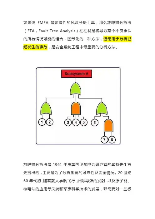
如果说FMEA是前瞻性的风险分析工具,那么故障树分析法(FTA,Fault Tree Analysis)往往就是将导致某个不良事件的所有情况可能的组合,图形化的一种方法,通常用于分析已经发生的事故,是安全系统工程中最重要的分析方法。
故障树分析法是1961年由美国贝尔电话研究室的华特先生首先提出的,主要是为了分析系统的可靠性及安全情况。
20世纪60年代初,随着载人宇航飞行,洲际导弹的发射,以及原子能、核电站的应用等尖端和军事科学技术的发展,都需要对一些极为复杂的系统,做出有效的可靠性与安全性评价;故障树分析法在航空和航天的设计、维修,原子反应堆、大型设备以及大型电子计算机系统中得到了广泛的应用。
故障树分析法从一个不幸事件开始(也可能是假定的不幸事件),自上而下、一层层的寻找顶事件的直接原因和间接原因事件,直到基本原因事件,并用逻辑图把这些事件之间的逻辑关系表达出来。
故障树分析法的本质是一种逻辑因果关系图。
逻辑门的输入事件是输出事件的“因",逻辑门的输出事件是输入事件的"果"。
上图中的绿色符号代表的是或的关系,表示任何一个“因”都可以得到“果”,而橙色的符号代表的是和的关系,表示若干个“因”都需要具备,才可以得到“果”。
总的说来,故障树分析法具有以下一些特点:故障树分析法是一种从系统到部件,再到零件,按“下降形”分析的方法,用来分析零件、部件或子系统故障对系统故障的影响,其中包括人为因素和环境条件等在内。
故障树分析法对系统故障不但可以做定性的而且还可以做定量的分析;不仅可以分析由单一构件所引起的系统故障,而且也可以分析多个构件不同模式故障而产生的系统故障情况。
故障树分析法也存在一些缺点,其中在于构造故障树的多余量相当繁重,难度也较大,对分析人员的要求也较高,因而限制了它的推广和普及。
在构造故障树时要运用逻辑运算,在其未被一般分析人员充分掌握的情况下,很容易发生错误和失察。
Software FMEAOpportunities and benefits of FMEA in the development process of software-intensive technical systemsOliver MäckelSiemens AGSimulation and Risk ManagementCT PP 281730 MünchenTechnical systems are prevalent in many areas of our society. Nowadays they often include a considerable amount of software. Identification and avoidance of technical risks is of major importance in the development of these software-intensive technical systems. A powerful analysis technique in the development process for technical systems is the Failure Mode and Effects Analysis (FMEA). This technique has proved very effective in avoiding failures in many areas of industry. However, there is to date no widespread use of the FMEA technique for software-intensive systems. Objectives and benefits of carrying out FMEAs on software will be discussed along with advantages, areas of application, weaknesses and constraints.IntroductionTechnical systems are prevalent today in many areas of our society. Due to economic rationalization and the necessity to meet increased requirements regarding performance and ergonomics an ever-growing number of complex tasks are being automated. An increasing dependence of society on the safe and reliable operation of these systems is the consequence. As an example, a faulty ticket vending machine is certainly a nuisance for the user and may also lead to substantive damage. The unintentional inflation of an airbag without any underlying vehicle collision on the other hand could lead to serious injury or even fatalities. The catastrophic failure of an on-board aeroplane computer could lead to great loss of life.Today technical systems often contain considerable amounts of software, which already constitutes an essential part of the system. It is a fact that new motor vehicles these days contain nearly 50 computer systems [1]. Extremely high safety and reliability levels are required of these mainly software-intensive systems. Examples can be found by considering costly capital equipment, especially aeroplanes and rail vehicles. High safety and reliability levels are also required for mass-produced products such as motor vehicle components, for industrial automation equipment etc [2]. These requirements necessitate, especially under the consideration of increased time-to-market and cost-to-market pressure, a risk-oriented development for software-intensive technical systems.Failure Mode and Effect AnalysisThe Failure Mode and Effects Analysis (FMEA) [3, 4] is an important analysis technique in the development process of technical systems. It was developed by NASA in the USA [7] in the early sixties for the Apollo Project. In the automobile industry it is standard procedure for planning and development [8]. In other areas of industry [9] FMEA can be found as a methodological component of quality management. The FMEA is acknowledged to the industry in many ranges [8, 9, 10].In a preventing way the FMEA takes failure behaviour and causes into consideration and evaluates associated risks with respect to occurrence, severity and detection. The simplicity and efficiency of the technique has proved its value and,furthermore it is recommended in relevant Standards [5, 6] for the development of safety-critical systems.FMEA for software (SW-FMEA) - Goals and BenefitsIn relation to hardware failure behaviour and human error it is gradually becoming more important to view the failure behaviour of software and its effects. This must be taken into account by the development of technical systems. FMEA is an established technique to avoid failures in technical systems. A timely performed FMEA is risk management instead of crisis management [15]. In the early phases of software development where the costs for changes are small (Fig. 1) and willingness to change is high, it makes sense to identify and avoid failures in a preventive way. By evaluating the individual risks a differentiation between high risk and low risk components, modules and functions can be achieved. This makes a risk-oriented development of software-intensive systems possible.relative number of faultsrelativ number of detected faultsCosts for faultcorrection per fault (TDM)Analysis Design CodingModul-testSystemtestField10%Fig. 1: Fault occurrence, fault elimination and fault correction costs in software development [15]A SW-FMEA is the consitent continuation of the FMEA of the system (system FMEA: SFMEA) for analyzing software-intensive components of the considered system. Their results find their way back to the FMEA of the system. However, the FMEA technique is not yet widely used for software-intensive systems. General use of these analyses in the development of technical systems is more important the more the requirements for time-to-market and cost-to-market increase.SW-FMEA!system as part of the FMEA of the system!during the softwareof critical functions!for the identification of critical modulsFig. 2: When should a SW-FMEA be performed?The SW-FMEA is a systematic, structured technique for the review of the software architecture or the software design with respect to technical risks (e.g. safety, reliability or availability). The SW-FMEA is used for knowledge transfer. The knowledge of different departments, like for example system development, software development, test and service, is brought together and used during the FMEA in the team. So the number of views on or into a system and a system's software increases itself.ProcedureThe SW-FMEA is carried out as a supplement to a FMEA of a system. It is used for architecture or design review during the development. The SW-FMEA should be performed before the implementation of the software. It may not be executed on software source code (Fig. 2).The SW-FMEA should also be executed in a team. This team has got members of different functional areas, like system development, software development, test and service.The SW-FMEA is carried out in following steps:1. The software to be examined is divided in components, modules and functions. A tree-similar structure develops.2. For every component defined in the system structure the function has to be described.The function of a subcomponent represents a partial function of the superordinate component.3. Corresponding possible failures and faults are assigned to every function of acomponent. The failure effects can be found then in the superordinate components. The failure causes are as a possible failure or fault listed in the subordinate components.4. If a risk evaluation is supposed to be carried out," the severity of the failure effects (in German: Bedeutung des Fehlverhaltens: B-value), " the probability of occurence (in German: Auftretenswahrscheinlichkeit: A-value) and" the detection probability of the failure causes (in German: Entdeckungswahrscheinlichkeit: E-value) will be listed.5. Then the definition of measures for the improvement of the software through avoidanceof possible faults or errors or the optimized detection of failures follows. This can happen for example through improved processes of development or through planning of special test cases. The evaluation of components, modules and functions with more or less risks follows on the basis of the quantitative risk evaluation.Due to the manifold connection possibilities of components, modules and functions a SW-FMEA should be carried out by the support of a FMEA tool [12]. The management of the SW-FMEA will be much simpler through that and the realization will get more efficient. DifficultiesIn the practice some weak spots during the realization of the SW-FMEA exist. In total the risk evaluation turns out in a more difficult way than in a conventional SFMEA. The experience shows that on the average larger risk priority numbers (RPN) are obtained. From a direct comparison of the risk priority numbers with conventional SFMEAs and/or between SW-FMEAs must be warned.Fundamentally two aspects which were criticized repeatedly within the framework of the conventional SFMEA [13] should be considered in particular at the evaluation of SW-FMEAs: " The derivation of thumb rules for the initiation of measures must even be project-specific or singlerisk oriented. Global use of thumb rules for the initiation of measures, as "for all risks with a RPN > 100 a measure has to be defined" are senseless [13] and proved to be useless in particular at SW-FMEAs." The same risk will be evaluated from different teams and/or different expert often differently. A comparison over several FMEAs must fail from that.Due to that a new procedure for the value formation at SW-FMEAs for the probability of occurrence (A-value) and the detection probability (E-value) is defined (based on a procedure discribed in [10]). The aim is an objective and usable risk evaluation.The evaluation of the severity (B-value) shall be done in analog mode to the SFMEA in order to receive continuously consistent evaluations.The occurrence and the detection takes off with software-intensive systems significantly from the complexity of the individual modules. At conventional SFMEAs the disturbance rate or probability of components out of the field are used within the risk evaluation for the determination of the A-value. For software this relation and transformation for the specific context must be determined first (Fig. 3). Test, verfication and maintenance strategies for thedetermination of the E-value are used in the conventional SFMEA. Test and review efficiency can be used useful to determine the E-value for software in combination with the respective module size or complexity (Fig. 4).modul complexityf a i l u r e o c c u r r e n c e f r e q u e n c ymodul complexityP r o b a b i l i t y o f f a i l u r e d e t e c t i o nFig. 3: Thumbsketch of a relation (probability of occurence / module complexity) including transformationto A-value Fig. 4: Thumbsketch of a relation (probability of detection / module complexity) including transformationto E-valueActually practical values may be determined at a SW-FMEA as follows. The evaluation of the occurrence and detection probability will be done in two steps. First an initial value has to be defined for the occurrence probability depending on the module complexity (Fig. 5).This will be reduced then depending on the process quality of the carried out avoidance measures. Individual avoidance measures are for example: " Structured analysis " Object-oriented analysis and design " Formal design methods " Design and coding standards" Standardized programming language " Validated compiler or even compiler which are well-proven in use The in each case used measure combination causes a more or less effective and efficient process. The reduction of the initial value depends on this.p r o c e s s q u a l i t y f o r t h e a v o i d a n c e o f f a u l t sp r o c e s s q u a l i t y f o r th e d e t e ct i o n o f f a u l t s a n d f a i l u r e s modul complexityMeasure should be initiated directlyFig. 5: Determination of the value for probability ofoccurance Fig. 6: Determination of the value for detectionprobabilityThe same procedure is used for detection probability value. First an initial value of 10 points is assigned independently from the module complexity (Fig. 6).Then this will be reduced depending on the process quality of the carried out detection measures. Detection measures for fault detection before system delivery are for example:" Formal verification" Reviews" Functional test (black box-tests) " Equivalence class tests" Static analysis " Data and control flow analysis" Structure-oriented tests with statement, branch or path coverage" Interface tests" Stress testsDetection measures for detection of failures during the systems runtime are for example:" Defensive programming" Failure Assertion ProgrammingThe influence for the enlargement of the fault detection is evaluated according to the used measure combination. The respective measure combination leads analog to the avoidance measures to a more or less effective process quality, by which the decrease of the initial value is defined.Definitively the risk priority number (RPN) is formed from the failure severity (B-value), the occurrence probability (A-value) and the detection probability (E-value).In this case the evaluation of the process quality turned out in a more difficult way than expected. The possible combinations of the measures are diverse and the corresponding benefit of a measure combination is only very heavily appraisable on an ordinal scale. Furthermore almost the same A and E-values were turned out for small software-intensive systems through almost identical measures or measure combinations for all failure causes. StrengthsThe SW-FMEA is simple and systematic. In an efficient way the SW-FMEA allows the structured analysis of a software architecture or a software design. With the aid of the SW-FMEA critical functions or modules and their risks will be identified systematically. This enables early a risk based development for example" through the organization of measures to avoid software faults," trough the initiation of measures for the detection of faults bevor the delivery or" the initiation of measures for the detection of failures during the runtime and" through the derivation of propositions for the optimization of the software structure.Risk based and disturbance based test cases and the appropriateness of tests and tests evaluates as soon as critical development instruments are worked out or identified.In addition to that maintenance rules in order to guarantee the safe and reliable operation of the software-intensive system within the specified environmental conditions are worked out permanently.ConclusionThe optimization of the software architecture and the software design and the derivation of test cases lead directly to an improvement of the software-intensive system. Since particularly these qualitative results stand in the foreground, the difficulties during the objective formation of values are negligible. Strengths and benefits of a SW-FMEA outweigh the difficulties from that.The SW-FMEA is well suitable as a systematic risk based review method.It forces the developer to a structured way of thinking.The software developer, who thinks during the development functionally, is forced, to think in an failure-oriented way.He has to build up the entire figure of the failure event from the effects down to the causes.In the analysis or design phase the respective system may be analyzed with respect to specific risk features by the use of a SW-FMEA. This is based on a systematic and structured dividing of the system.For safety-related software the derivation of safety-oriented, mostly failure-oriented test cases is just interesting. These are normally usable within the framework of a validation of the software or the system and increase next to the quality also the confidence into the developed software-intensive and safety-related systems.PerspectiveThe base forms a careful risk analysis and risk evaluation for the development of technical systems. The conversion of these analyses during the development of technical systems just wins more and more importance regarding to the rising time-to-market and cost-to-market requirements.Moreover, missing or unclear risks can lead to gaps in the further development process. This may lead to risks or hazards. The SW-FMEA helps by the capturing of the missing or unclear risk requirements related to software components.Due to the importance of the FMEA for general quality processes [8, 9, 10] and due to the demands from standards [5, 6,] the SW-FMEA will find in particular further circulation as a method for preventive failure avoidance. The systematic and structured procedure supports an architecture and design review just with regard to risk based questions.Next to the up to now described possible applications of the SW-FMEA in the analysis and the design phase the SW-FMEA can also be used effectively in the requirement analysis in the sense of a systematic risk based review of the requirements specification in order to increase the quality of the requirements specification [11]. Following advantages turn out in this case:" Early understanding of the requirements" Improvement of the communication between the author of the requirements specification and the software design team" Early recognition of mistakes in the requirementsFor big software-intensive systems the SW-FMEA will be recommended as a good method for the review of the requirements specification [11] in the same way.During the development of safety-critical systems in automotive industry, in aviation technology and in industrial automation the SW-FMEA will establish itself just the same as for availability-critical systems in the telecommunication.References[1] Jüttner, P., Schweikl, U., Siemens AT, SoftwareDevelopment in Automotive Business, Gast-vortrag Uni Oldenburg, Mai 2000[2] Liggesmeyer, P., Qualitätsicherung softwarein-tensiver technischer Systeme, Spektrum-Verlag Heidelberg, 2000[3] DIN 25448, Ausfalleffektanalyse (Fehler-Mög-lichkeits- und -Einflussanalyse), Mai 1990[4] IEC 812, Failure Mode and Effects Analysis[5] IEC 61508, Functional safety of electrical /electronic / programmable electronic safety-related systems[6] prEN 50128, Bahnanwendungen – Software fürEisenbahnsteuerungs- und Überwachungs-systeme, Juli 1998[7] Müller, D. H., Tietjen, Th., FMEA-Praxis - DasKomplettpaket für Training und Anwendung,Carl-Hanser-Verlag, München, 2000[8] Zebedin, H., FMEA aus Sicht eines Motorenent-wicklers, in: Qualität und Zuverlässigkeit, Vol.43, Nr. 7, Seite 826 ff., Carl-Hanser-Verlag,München,1998[9] Gralla, D.; Heinz, S., Fehlermöglichkeits- undEinflussanalyse FMEA, in: EI – Eisenbahnin-genieur, Vol. 49, No.74, S. 43 - 47, Juli 1998 [10] Schiegg, H.; Viertlböck, M.; Kraus, T.Prozeßbegleitend und frühzeitig - System-Produkt-FMEA mit objektiver Kennzahlbildungbei einem Automobilzulieferer, in: Qualität undZuverlässigkeit, Vol. 44, Nr. 7, Seite 879 - 884, Carl-Hanser-Verlag, München,1999[11] Lutz, R. R., Woodhouse, R. M., RequirementsAnalysis Using Forward and Backward Search, in: Annals of Software Engineering, SpecialVolume on Requirements Engineering, 1997 [12] Mäckel, O., Schuster, J.-U., Siemens ZT/A&D,Interner Bericht (A&D GT4/98-17): FMEAWerkzeugvergleich, München, November 1998 [13] Kistner, W., FMEA noch besser anwenden, in:Qualität und Zuverlässigkeit, Vol. 41, Nr. 7, S.827 – S. 830, Carl-Hanser-Verlag, München,1996[14] Möller, K. H., Ausgangsdaten für Qualitäts-metriken - Eine Fundgrube für Analysen, in:Ebert, C., Dumke , R. (Hrsg.) , Software-Metri-ken in der Praxis, Springer-Verlag, Berlin, 1996 [15] Mäckel, O., Mit Blick auf's Risiko - Software-FMEA im Entwicklungsprozess softwareinten-siver technischer Systeme, in: Qualität undZuverlässigkeit, Vol. 46, Nr. 1, Carl-Hanser-Verlag, München, 2001。
关于IEC(国际电工委员会)制定的可靠性标准,你知道多少?!作为装备综合性能之一的可靠性指标,已作为一项考核要求纳入到研制合同中,而达到可靠性指标要求,不是只靠图纸上的设计就能实现的,因为不管产品可靠性设计得多好,人们不可能预计到所有的错误和不足。
而解决这些问题,除要采用一系列的工程专业技术外,还要采用提高可靠性增长的技术,制定提高可靠性的措施,将有效的纠正措施纳人到系统的设计中去,实现系统的固有可靠性增长,是达到产品可靠性目标要求的有效途径。
而推进可靠性增长技术,就要制定相应的标准来推动可靠性增长技术的标准化。
可靠性标准的发展20世纪80年代,可靠性增长技术开始从军用转为民用,国际电工委员会(International Electro technical Commission,简称IEC)先后制定了4个可靠性增长技术标准,对推进可靠性增长技术、提高和保证军民品的可靠性做出了突出贡献。
IEC的宗旨是促进电工标准的国际统一,电气、电子工程领域中标准化及有关方面的国际合作,增进国际间的相互了解。
IEC的工作领域包括了电力、电子、电信和原子能方面的电工技术。
随着可靠性和标准化发展需要,国际电工委员会(IEC)决定成立一个名为“电子元件和设备可靠性”的技术委员会,即TC56。
伴随可靠性工程技术的不断拓展,维修性和维修保障性的相继提出,该技术委员会的名称也跟着不断发生改变。
1973年起TC 56更名为“可靠性与维修性技术委员会。
1991 年起又更名为“可信性”(Dependability)技术委员会,此名称一致沿用至今。
根据可靠性标准的需要,TC56在编制工作上采取了按专业划分工作组的方式,目前有四个大工作组:可信性名词术语工作组、可信性技术工作组、可信性管理工作组和系统与软件可信性工作组,每个大工作组还根据标准修订任务和专业分工下设若干小组。
可靠性技术标准体系框架如下图所示,可分为:基础标准,过程指南标准、技术标准标准和试验测试标准。

PUBLICNXP, THE NXP LOGO AND NXP SECURE CONNECTIONS FOR A SMARTER W ORLD ARE TRADEMARKS OF NXP B.V.M A R C H 2022S32K3 SAF Quick StartGuideW H AT I S S A F(S AF E T Y S O F T WAR E F R AM E W O R K)Premium safety software product provided by NXP (s32-safety-software-framework-saf) Software modules providing safety functions:-Device HW self test-Operation mode selection-Safety checks / tests-Device recoveryCompatible solution across NXP S32 processorsQuality: Automotive grade production qualitySafety: ISO 26262 Functional Safety compliance (up to ASIL-D)S 32K3 S AF D E L I V E R AB L E S Source code, User manuals, SAF demo applicationStandalone installer (exe)Source code, User manuals, SAF demo applicationS32 Design Studio installer (update site zip)Quality documentation (Quality Matrix, Traceability Matrix, Test Specification, Summary Test / Test / Code Coverage / Compiler Warning / His / Misra / Profile /Ram Size / Size / VSMD Reports, APIs Equivalence class analysis)Quality Package (zip)Safety documentation (SAF Safety Manual, Safety Analysis FMEA, Fault Coverage Estimation)Safety Package (zip)Specifies licenses used by the productSoftware Content Register (txt)Information on the content of the releaseRelease Notes (txt)List of Known Defects (published every week)LKOD (xlsx)S32K3S AF D O W N L O A DAvailable from under:MY NXP->Software Licensing and Support->S32K3 Premium Software->S32K3 -Safety Software Framework:−Standalone installer (exe)−S32 Design Studio installer (update site zip)−Quality Package, Safety Package, SoftwareContent Register, Release Notes−List of Known DefectsS32K3S TAN D A L O N E I N S TAL L AT I O NSAF is installed in c:\NXP\S32K3_SAF_1.0.0:−SAF modulesBist Built in self testeMcem Extended microcontroller error managermSel Mode selectorsBoot Safe bootsCheck Square check, check the checkers component sReco Software recovery−Check the release notes for information about the releaseB U I L D AN D R U N S AF D E M OSAF demo available showing usage of all modules:-mSel mode selection-sCheck startup/runtime/shutdown tests-eMcem fault handling-sBoot checks-mSel/sReco shutdownBuild from command line by command:launch.batDebug on board using debugger scripts inc:\NXP\S32K3_SAF_1.0.0\S32_SAF_Demo\config\S32K3XXD O C U ME N TAT I O N TO S TAR T W I T H-SAF release notes (S32K3_SAF_1.0.0_ReleaseNotes.txt)-SAF modules user manuals (doc folder in each module folder, for example S32K3_SAF_SCHECK_UM.pdf)-SAF safety manual (available from SAF Safety package zip,S32K3_SAF_Safety_Manual.pdf)-SAF demo user manual (S32K3_SAF_IA_UM.pdf)-ISO26262 Functional Safety standard (available from ISO)S AF P R E M I U M S O F T WAR E-SAF is a premium software so license fee has to be paid-To get access to software/price information contact NXP sales/marketing (NXP support)-Any more questions? Ask on NXP support。
失效模式与影响分析失效模式与影响分析(英文:Failure mode and effects analysis,FMEA),又称为失效模式与后果分析、失效模式与效应分析、故障模式与后果分析或故障模式与效应分析等,是一种操作规程,旨在对系统范围内潜在的失效模式加以分析,以便按照严重程度加以分类,或者确定失效对于该系统的影响。
FMEA广泛应用于制造行业产品生命周期的各个阶段;而且,FMEA在服务行业的应用也在日益增多。
失效原因是指加工处理、设计过程中或项目/物品(英文:item)本身存在的任何错误或缺陷,尤其是那些将会对消费者造成影响的错误或缺陷;失效原因可分为潜在的和实际的。
影响分析指的是对于这些失效之处的调查研究。
基本术语失效模式(又称为故障模式)观察失效时所采取的方式;一般指的是失效的发生方式。
失效影响(又称为失效后果、故障后果)失效对于某物品/项目(英文:item)之操作、功能或功能性,或者状态所造成的直接后果。
约定级别(又称为约定级)代表物品/项目复杂性的一种标识符。
复杂性随级数接近于1而增加。
局部影响仅仅累及所分析物品/项目的失效影响。
上阶影响累及上一约定级别的失效影响。
终末影响累及最高约定级别或整个系统的失效影响。
失效原因(又称为故障原因)作为失效之根本原因的,或者启动导致失效的某一过程的,设计、加工处理、质量或零部件应用方面所存在的缺陷严重程度(又称为严重度)失效的后果。
严重程度考虑的是最终可能出现的损伤程度、财产损失或系统损坏所决定的,失效最为糟糕的潜在后果[1]。
历史从每次的失效/故障之中习得经验和教训,是一件代价高昂而又耗费时间的事情,而FMEA 则是一种用来研究失效/故障的,更为系统的方法。
同样,最好首先进行一些思维实验。
二十世纪40年代后期,美国空军正式采用了FMEA[2]。
后来,航天技术/火箭制造领域将FMEA用于在小样本情况下避免代价高昂的火箭技术发生差错。
其中的一个例子就是阿波罗空间计划。
OTS=off tooling samples 即全工装状态下非节拍生产条件下制造出来的样件.用于验证产品的设计能力.(用于验证设计出来的产品是否符合客户要求,同时也是对生产工装的验证) 同时OTS也可以叫模具样品,LH 要求汇总书(一个项目的所有资料)TPB 产品技术描述(图纸、技术供货条件等等)DKM 数据控制模型(汽车形状1:1的基准样车)P P认可=计划认可(决定投入批量生产)B B认可=采购认可(对生产手段的投资认可)D D认可=零件生产和供应认可(为零批量)BMG 产品工程性能认可EM 进行首批样件检验的首批样件,首批样件检验也称首批样件认可。
EMPB EMPB=首批样件检验报告(供货商对其样件检验的文件)2TP 两日生产(供货厂的批量预生产,用来验证批量能力)PVS 生产试制批量0S 零批量(在批量生产条件下的总演习)SF 批量认可(对批量生产的产品认可)EPF (批量供货)计划认可KAF 集团路试验收(质量方面的批量认可)SOP 生产启动(批量生产启动)ME 市场导入(提供给销售商)CAD 计算机辅助设计COP 沿用件(与先前车型通用的零件)CKD 全部拆散SKD 部分拆散HT 自制件KT 外购件(外部供货厂生产的零件)KD 售后服务OTS 用批量生产的模具生产的零件TE 技术开发部PE (合资厂中的)产品工程部TL 技术供货条件TS 产品零件表ZP 检查点ZSB 总成AEKO (产品)改动的控制组织常用英文缩写对照表汽车行业英文缩写(2009-05-06 14:34:33)OSM- Outside of MaterialOTC Over The Counter 非处方药,可在柜台上卖的药PA Program Approvalpallet n. 托盘Passenger Vehicle 乘用车PAT- Program Attributes Team 产品属性小组PDL Product Design LetterPH Proportions&HardpointsPIPC- Percentage of Indexes with Process Capability 能力指数百分比PIST- Percentage of Inspection points Satisfying Tolerance 检测点满意工差百分比PMT- Program Moudle Team 产品模块小组PO Purchase OrderPPAP- Production Part Approval Process 生产件批准程序PPSR Production Preparation Status ReportPQA Process Quality AssurancePR Program ReadinessPre-Launch 试生产price-driven costing 价格引导成本Production Preparation-Final Nissan - PT2/Renault - PPProduction Preparation-Initial Nissan - PT1/Renault - PPP3Production Trial Run 试生产Prototype 样件QFD Quality Funtion Deploy质量功能展开QFTT Quality Functional Task TeamQR- Quality Reject 质量拒收QS Quality StandardRAN Release Authorisation Numberreverse 倒车档RFQ Request For Quotation询价RKD Reverse Knock DownRLQ Receiving Lot QuantityROC Rate of ClimbROI return on investment 报酬率ROP Re-Order PointRTO Required To OperateSAIS Supplier Assessment & Improvement SystemSC Strategic Confirmation/significant Charac’teristicsSDS- System/ Design Specifications 系统/设计说明second gear 二档SFMEA System FMEAShipping Date 出货日、Invoice Date 发票日或On Board Date 装船日Side Windshield 侧窗玻璃SJ Strategic IntentSNP Standard Number of Parts1PP- First Phase of Production Prove-Out 第一次试生产3C Customer(顾客导向)、Competition(竞争导向)、Competence(专长导向)4S Sale, Sparepart零配件, Service, Survey信息反馈5S 整理,整顿,清理,清洁,素养8D- 8 DisciplineABS Anti-lock Braking SystemAIAG 美国汽车联合会ANPQP Alliance New Product Quality ProcedureApportionment 分配APQP Advanced Product Quality PlanBacklite Windshield 后窗玻璃Benchmark Data 样件资料bloodshot adj.充血的, 有血丝的BMW Bavarian Motor WorksSOW- state of work 工作申明SPC Statistical Process ControlSQA Supplier Quality AssuranceSREA- Supplier Request for Engineering Approval 供应商工程设计更改申请ST Surface TranferSTRS Supplier Test Report SystemSubcontractor 分承包商Sunroof Windshield 天窗玻璃SUV Sports Utility VehicleTAG Test Aptitude GraphiqueTCO Total Cost of Ownership 总持有成本TCRA Total Cost Reduction ActivityTGR Things Gone RightTGW Things Gone WorstTM Techinical ManualTPM Total Preventive MaintenanceTTO-Tool Try Out 工装验证UOM Unit Of MeasureVES Vehicle uation SystemVO- Vehicle Operation 主机厂VPP- Vehicle Program Plan 整车项目计划VQA Vehicle Quality AssuranceVTTO- Vendor Tool Try-Out 供应商工装验证WERS- World Wide Engineering Release System WVTA Whole Vehicle Type Approval凹坑 concave车床 lathe抽查试验spot check test出厂试验delivery test次品defective product调幅amplitude modulation (AM)调频 Frequency Modulation断差 offset对讲机 interphone法平面normal plane翻车rollover返工 re-doing防滑地板 no-skid floor仿真emulation副作用side effect改装厂 refitting factory隔热板heat shield后围侧板 rear wall side cover划痕 scratchC.P.M Certified Purchasing manger 认证采购经理人制度CB- Confirmation Build 确认样车制造CC- Change CutOff 设计变更冻结CCSC- critical/significant characteristicCCR Concern & Countermeasure RequestCCT Cross Company TeamCharacteristics Matrix 特性矩阵图COD Cash on Delivery 货到付现预付货款(T/T in advance) CP1- Confirmation Prototype 1st 第一次确认样车CP2- Confirmation Prototype 2nd 第二次确认样车Cpk 过程能力指数Cpk=Zmin/3CPO Complementary Parts OrderCraftsmanship 精致工艺Cross-functional teams 跨功能小组CUV Car-Based Ultility VehicleD1:信息收集;8DD2:建立8D小组;D3:制定临时的围堵行动措施,避免不良品流出;D4:定义和证实根本原因,避免再发;D5:根据基本原因制定永久措施;D6:执行和确认永久措施;D7:预防再发,实施永久措施;D8:认可团队和个人的贡献。
fmea是什么意思_fmea的中文意思【fmea】abbr. 故障模式与理象分析(Failure Mode and Effects Analysis) 【网络释义】失效模式与影响分析失效模式与影响分析(FMEA)是一种确定和预防产品及工艺过程问题的系统方法。
FMEA以预防缺陷、强化安全性以及提高客户满意度为重点。
失效模式与效应分析失效模式与效应分析(FMEA)作为一种风险分析方法在设计、制造中用以预防、避免差错的应用早已为人们所熟悉。
近.失效模式与效果分析(Failure Mode And Effect Analysis)预先危险分析(PHA Preliminary Hazard Analysis失效模式分析(Failure Model Effectiveness Analysis)参与新机型的导入和延伸机型的设计,针对产品客诉问题进行产品结构方面的改善;FMEA(失效模式分析)的制作等。
【词组短语】功能FMEA Functional FMEAProcess FMEA 程失效模式及后果分析; 过程; 工艺FMEA 工艺FMEA Process FMEA-PFMEA ; process FMEAFMEA ACI 美国混凝土学会标准structured FMEA 结构; 结构FMEAFMEA设计Design FMEA(Fail Mode and Effect Analysis)FMEA introduction 文件名称D FMEA 第三十八章FMEA方法FMEA method【例句】Is the process FMEA prepared and have improvement measures been established?准备和改善措施是建立在这个故障模式影响分析过程中吗?MetsoAutomation has implemented a Failure Mode and Effect Analysis (FMEA) programmeto extend the lifecyles and lower the cost of ownership of its products.Metso自动化已经实现了一个FailureModeandEffectAnalysis (故障模式和影响分析FMEA)程序,以便扩展其产品的生命周期并降低拥有权成本。
1.软件测试英语专业词汇2.NLV:Nation Language Version 本地化版本3.FVT:Functional Verification Testing 功能验证测试T:Translation Verification Testing 翻译验证测试5.SVT:System Verification Testing 系统验证测试6.fault--故障在软件中一个错误的表现。
7.feasible path--可达路径可以通过一组输入值和条件执行到的一条路径。
8.feature testing--特性测试参考功能测试(Functional Testing)9.FMEA--失效模型效果分析(Failure Modes and Effects Analysis)可靠性分析中的一种方法,用于在基本组件级别上确认对系统性能有重大影响的失效10.FMECA--失效模型效果关键性分析(Failure Modes and EffectsCriticality Analysis)FMEA的一个扩展,它分析了失效结果的严重性。
11.FTA--故障树分析(Fault Tree Analysis)引起一个不需要事件产生的条件和因素的确认和分析,通常是严重影响系统性能、经济性、安全性或其它需要特性。
12.functional decomposition--功能分解参考模块分解(modular decomposition)13.Functional Specification --功能规格说明书一个详细描述产品特性的文档。
14.Functional Testing--功能测试测试一个产品的特性和可操作行为以确定它们满足规格。
15.glass box testing--玻璃盒测试参考白盒测试(White Box Testing)16.IEEE--美国电子与电器工程师学会(Institute of Electrical andElectronic Engineers)17.incremental testing--渐增测试集成测试的一种,组件逐渐被增加到系统中直到整个系统被集成。
风险识别故障树安全生产危险有害因素辨识和安全评价是企业风险分级管控和隐患排查治理双重预防机制有效运行的基础工作。
为安全生产从业人员提供有效的定性定量分析工具,选择正确的辨识和安全评价方法必不可少。
本文根据有关规范和实际工作需要列出常见的几种使用方法,其中对矩阵法和作业条件危害性评价法进行列图说明。
安全检查表法(SCL)(危险源辨识方法)安全检查表(Safety Check List Analysis缩写SCA)是依据相关标准、规范,对工程、系统中已知的危险类别、设计缺陷以及与一般工艺设备、操作、管理有关的潜在危险性和有害性进行判别检查。
为了避免检查项目遗漏,事先把检查对象分割成若干系统,以提问或打分的方式,将检查项目列表,这种表就称为安全检查表法,它是系统安全工程的一种最基础、最便捷、应用最广泛的系统危险性评价方法。
安全检查表法是一种通用性定性安全评价方法,不仅用于查找系统中各类潜在的事故隐患,还对各检查项目量化,用于进行系统性安全评价。
安全检查表法(SCL)操作流程:组织检查表编写组-对系统进行全面细致的了解-收集与系统有关编制依据-分割剖析审查个单元并找出相关危害因素和列出清单-逐个找出对应的安全要求及措施并形成措施清单-按系统列出应检查问题的清单-实践检验并不断修改完善。
一般作业活动危险性分析(JHA)(危险源辨识方法)一般作业活动危险性分析(JHA)是对作业活动的每一步骤进行分析,从而辨识潜在的危害并制定安全措施。
这种方法的基本点在于职业健康安全是任何作业活动的一个有机组成部分,而不能单独剥离出来。
所谓的“作业活动”(有时也称“任务”)是指特定的工作安排,如“安装阀门”、“焊接管线”。
“作业活动”的概念不宜过大,如“大修机器”,也不能过细。
开展一般作业活动危险性分析能够辨识原来未知的危害,增加职业健康安全方面的知识,促进操作人员玑管理者之间的信息交流,有助于得到更为合理的安全操作堆积。
作为操作人员的培训资料,并为不经常进行该项作业的提供指导。
Engineering Design and Analysis Engineering Design and Analysis is a crucial aspect of any engineering project. It involves the application of scientific and mathematical principles to design, analyze, and evaluate the performance of various systems. This process requires a deep understanding of the problem at hand, the available resources, and thedesired outcome. In this response, I will discuss the importance of engineering design and analysis from multiple perspectives. From an engineering perspective, design and analysis are the foundation of any successful project. It allows engineers to identify the requirements and constraints of a system, develop potential solutions, and evaluate their feasibility. By thoroughly analyzing the design options, engineers can optimize the performance, reliability, and cost-effectiveness of the system. This ensures that the final product meets the desired specifications and performs as intended. Moreover, engineering design andanalysis also play a crucial role in risk management. By identifying potentialrisks and uncertainties early in the design process, engineers can develop strategies to mitigate them. This includes conducting thorough analyses, such as failure mode and effect analysis (FMEA) and fault tree analysis (FTA), to identify potential failure modes and their consequences. By addressing these risks proactively, engineers can enhance the safety and reliability of the system. From a business perspective, engineering design and analysis are essential for ensuring the competitiveness and profitability of a company. By optimizing the design, engineers can reduce production costs, improve energy efficiency, and enhance product performance. This can give a company a competitive advantage in the market, leading to increased sales and customer satisfaction. Additionally, by conducting thorough analyses, engineers can identify potential design flaws or inefficiencies before the product is manufactured, saving both time and money. Furthermore, engineering design and analysis also have significant societal impacts. By developing sustainable and environmentally friendly designs, engineers canminimize the negative impacts on the environment. This includes reducing energy consumption, minimizing waste generation, and using eco-friendly materials. Additionally, engineering design and analysis can also contribute to the development of innovative solutions to societal challenges, such as renewableenergy systems, efficient transportation networks, and clean water technologies. In conclusion, engineering design and analysis are crucial for the success of any engineering project. From an engineering perspective, it allows for the optimization of system performance, reliability, and cost-effectiveness. From a business perspective, it ensures competitiveness and profitability. From a societal perspective, it contributes to sustainability and the development of innovative solutions. Therefore, it is essential for engineers to invest time and effort in the design and analysis phase of a project to ensure its success and positive impact.。
ASSESSMENT OF THE ISO 26262 STANDARD, “ROAD VEHICLES –FUNCTIONAL SAFETY”Dr. Qi Van Eikema HommesSAE 2012 Government/Industry Meet ingJanuary 25, 2012Outline•ISO 26262 Overview•Scope of the Assessment •Strengths•Considerations for Improvements •Industry Feedbacks •SummaryISO 26262 Overview•Adaptation of IEC 61508 to road vehicles•Influenced by ISO 16949 Quality Management System•The first comprehensive standard that addresses safety related automotive systems comprised of electrical, electronic, and software elements that provide safety-related functions.•It intends to address the following important challenges in today’s road vehicle technologies:–The safety of new E/E and Software functionality in vehicles–The trend of increasing complexity, software content, and mechatronics implementation–The risk from both systematic failure and random hardware failureGeneral Structure of ISO 262623. Concept phase2. Management of functional safety2-5 Overall safety management 2-6 Safety management during item development 7. Production & Operation6-5 Initiation of product development at the software level6-6 Specification of software safety requirements6-7 Software architectural design 6-8 Software unit design and implementation6-9 Software unit testing6-10 Software integration and testing 6-11 Software verification5-5 Initiation of product development at the hardware level5-6 Specification of hardware safety requirements5-7 Hardware design5-8 Hardware architectural metrics 5-10 Hardware integration and testingC o r e p r o c e s s e s2-7 Safety management after release for production3-6 Initiation of the safety lifecycle 1. Vocabulary3-5 Item definition3-7 Hazard analysis and risk assessment3-8 Functional safety concept7-6 Operation, service and decommissioning7-5 Production8. Supporting processes8-5 Interfaces within distributed developments 8-6 Overall management of safety requirements 8-8 Change management 8-9 Verification 8-7 Configuration management 4. Product development: system level4-5 Initiation of product development at the system level4-7 System design4-8 Item integration and testing4-9 Safety validation 4-10 Functional safety assessment4-11 Release for production 6. Product development:software level5. Product development:hardware level5-9 Evaluation of violation of the safety goal due to random HW failures 4-6 Specification of the technical safety requirements 9. ASIL-oriented and safety-oriented analyses9-5 Requirements decomposition with respect to ASIL tailoring 9-6 Criteria for coexistence of8-10 Documentation8-11 Qualification of software tools8-13 Qualification of hardware components 8-14 Proven in use argument8-12 Qualification of software components 9-7 Analysis of dependent failures 9-8 Safety analyses10. (Informative) Guidelines on ISO 26262M a n a g e m e n tS u p p o r tI S O 26262 a f f e c t s a l l a r e a sScope of This Assessment•Conducted in June-July 2011, based on DSI draft published in 2009.•Final standard (FDIS) was published in November 2011. •Future discussions should be based on the FDIS version of the standard.•Review Focus—How well can the standard provide safety assurance for the complex software-intensiveautomotive electronics and electrical systems?•Emphasizing safety management and safety culture–Major accidents in large complex systems are notcaused by the failure of technical components, but rather organization factors influencing the design,manufacturing, and operation of the system. •Prescribes a systems engineering process –Safety is an emergent property of the system, andrequires systems engineering approach.•Departure from safety as anafter-thought:–IEC 61508: safety function–ISO 26262: provides theframework and vocabularyfor hazard elimination in thefirst place•Systems engineeringframework•Safety measure vs.safety mechanisms Leveson 2011•Disassociate hazard risk level from probabilistic failure rate:–IEC 61508: SIL uses component failure rateSeverityExposureControllabilityASIL D: highest safety integrity level A: lowest safety integrity level QM: quality managementASIL Assessment•Consider only use S (severity)–Estimation of E can be subjective•Standardize ASIL assessment among OEM and Suppliers–Legal liability of different ASIL assessment–Development cost affecting industry competitiveness–OEM inconsistency among the same component from thesuppliers.–Must be careful with component ASIL standardization—safety of a component can only be assessed in the context of the specific system implementation.–The government may play a role in ASIL classification.Provide More Guidance on Hazard Elimination •Safety measure is not clearly explained in the document. But this concept is the key to hazard elimination in the first place—the most effective and least costly approach.•Safety Mechanism is explained in detail throughout the document.But this concept is like the safety function concept in IEC 61508, and is a less effective safety measure.•The standard may want to add a section in Part 1 to further clarify the departure from IEC 61508’s design philosophy.•Investigate other hazard analysis methods that can provide more effective guidance on how to identify and eliminate hazards indesign. One such method is the System Theoretic Process Analysis (STPA) based on System Theoretic Accident Modeling Process(STAMP).Separate System Safety from Reliability EngineeringSafety ≠ Reliability–Reliability engineering focuses on component failures.–System can be unsafe when none of thecomponent fails.•The required function may be unsafe.•Software or human do not fail, and have nofailure rate.–System can still be safe when componentsfail.Reliability Engineering Methods in ISO 26262•Hardware Architecture Metrics--Based on random failure of components. •Failure Modes and Effects Analysis (FMEA):–Developed to predict equipment reliability.–Forward search based on underlying single chain-of-events and failure models –Initiating events are failures of individual components–Quickly become impractical for complex systems•Fault Tree Analysis (FTA):–Top-down search method–Based on converging chains-of-events accident model.–Tree is simply record of results; analysis done in head. Lack of guidance.–Assume independence of the failure, which is not always true.•Safety Case Approach–Confirmation bias–the use of Quantitative Risk Assessment–Independent reviewers are less familiar with the designThe FMEA and FTA comments are based on Professor Nancy Leveson’s system safety class lecture notes.Recommendations for Strengthening Safety Engineering•Independent review team may not want to focus on the correctness of the safety case, but rather independently conduct hazard analysis to find out whether all causes of the hazards have been analyzed and addressed. •Investigate the effectiveness of STPA and other system safety methods in order to adapt them into the standards to provide guidance on how to design for system safety.Software Safety•Follows software systemengineering process•Promotes good softwarearchitecture practices•Best practices in softwaredesign•Addresses hardware failure•On Par with other softwaresafety standards such as DO-178Comments:•Unlike hardware, software does not fail.•Software faults are due to design errors, but the standard does not offer a way to identify design errors that can cause hazard.•Good systems engineering process and software architecture design are necessary but not sufficient to ensure system safety.Production and Operation•Great to have a complete lifecycle view of the safety. •Unfortunately, the standard provide almost no guidance on how to ensure the safety in these two important stages.•Thought starters:–How to identify key characteristics in manufacturing that are critical to safety?–Aftermarket software and components safety?–How to check and ensure sensors, actuators, and communication channels are safe throughout the lifecycle of the vehicle?–Is there a need for Government-mandated yearly safety checkup?–Education and training for service technicians?Incorporate Design Guidelines for Safe User Interaction•The standard has no mention of safe user interactions •Automation in the airplane cockpit has led to some major accidents•Automotive companies do have Human-Machine Interface design groups•Recommendations:–Learn from the accidents in cockpit automationliteratures–Incorporate guidelines for safety user interactiondesign in the futureIndustry’s Views—Pro’s•ISO 26262 is well regarded by industry and is seen as necessary.•Many companies have at least tried it on pilot projects. •GM has used it to ensure Volt’s battery functional safety. •Industry recognizes it is valuable to have safety standard to address the growing complexity of Cyber-PhysicalSystems.•No discrepancy with mature product development process, and it is easy to implement.•Aligns well with the model-based development process.Industry’s Views--Cons•Amount of documentation efforts•Not convinced that the software development methods are sufficient to guarantee safety•Since the standard is about the entire product life cycle, the effect of the standard will take some time to show.•The concept phase is easy to implement, but there is difficulty to integrate a pilot project into the rest of the system that was not developed based on the standard.•ASIL classification harmonization•“Proven in use” argument is not useful–Takes too long to collect sufficient data–The definition in the standard makes it a step that will never be visited •Qualification of software tools–The large number of software tools used in development–Comment: software tools are software. How will one quantify the probability of software making mistakes?Summary of Recommendations1.Consider only using severity for ASIL assessmenternment may want to consider playing a role in ASIL standardization–However, the ASIL assessment must depend on the context and the design configuration of the system.3.The standard may want to add a section to emphasize hazard elimination beforedetection and control4.Research activities may want to investigate the effectiveness of system theory basedhazard causal analysis in automotive complex cyber-physical systems– E.g. STAMP model and STPA.5.Fundamental research is needed for the safety of complex software-intensivesystems today, including those in the current automobiles:–The effect of complexity on safety is not well quantified–The effects of software engineering best practices on safety may be insufficient to ensure safety. New and different approaches may need to be developed.ernment may want to play a role in certifying software tools used for thedevelopment of safety critical systemsernment may want to consider regulating the safety of E/E systems after thevehicle is sold。